
TST60 Integrated Closed loop Stepper Motor
Table of Contents
1. Product Introduction
1.1 Product Introduction
1.2 Safety Instructions
2. Product Functional Block Diagram
3. Driver Parameters and Products
4. Product Schematic and Mechanical Installation Drawings
5. Preparations Before Start
4.1 Installing the Host Computer Software
4.2 Installing the Hardware
6. Connecting the Power Supply
5.1 Selecting the Power Supply Voltage
5.2 Selecting the Power Supply Current
7. Installation and Wiring
6.1 Connecting the Power Supply
6.2 Inputs and Outputs
6.3 Connector Pin Definitions
8. DIP Switch Settings
8.1 Subdivision Settings
8.2 Running Direction Settings
9. TTL Communication Parameter Settings and Data Cables
10. Wires and Accessories
11. Error Codes
1. Product Introduction
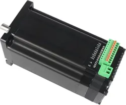
Thank you for choosing the TST60 series integrated motor products. The TST60 series integrated motors are a perfect
combination of drivers and stepper motors. They perfectly integrate stepper motor and drive technologies, which can not
only save installation space but also simplify wiring, saving you design and production costs. It is your first choice when
using stepper system solutions. The TST60 series products have the excellent characteristics of integrating control and
drive.
1.1 Product Features
※ Operating Voltage: DC24V~DC50V
※ Drive Output Current: 0.2A~5A
※ Control Mode: Pulse + Direction
※ Encoder Mode: 1000 Lines
※ Output Torque: 0.2NM~4.5NM
※ Communication Method: TTL
※ 3 digital inputs, high level can directly receive 3.3~24V DC level, maximum frequency 300KHZ, 1
group of independent digital output, collector OC output, maximum withstand voltage 30V, maximum sink
or output current 50mA
1.2 Safety Instructions

※ The transportation, installation, use or maintenance of this product must be carried out by personnel
with professional qualifications and familiar with the above operations.
※ In order to minimize potential safety hazards, you should follow all local and national safety codes
when using this equipment. Different regions have different safety regulations, and you should ensure
that the installation and use of the equipment comply with the regulations in your location.
※ System errors may also cause equipment damage or personal injury. We do not guarantee that this
product is suitable for your specific application, nor can we assume responsibility for the reliability of your
system design.
※ Please be sure to read all relevant documentation before installation and use. Incorrect use may cause
equipment damage or personal injury. Please strictly follow the relevant requirements before installation.
※ Please be sure to confirm the grounding of all equipment in the system. Non - grounded systems
cannot ensure electrical safety.
※ Some components inside the equipment may be damaged by external static electricity. Operators
should confirm that they are free of static electricity before contacting the product, avoid contacting
objects prone to static electricity (such as chemical fibers, plastic films, etc.), and place items on a
conductive plane.
※ If your equipment is placed in a control cabinet, please close the outer cover or door of the control
cabinet during operation, otherwise it may cause equipment damage or personal injury.
※ During operation, depending on the protection level of surrounding equipment, the product may
completely fail or the surface may generate a lot of heat. Even when the motor is not running, the power
supply and control cables may still carry a high voltage.
※ It is strictly forbidden to hot - swap cables when the system is running. The arc generated by hot -
swapping may cause harm to both operators and equipment.
※ Please wait at least ten seconds after powering off before touching or removing the wiring. Capacitive
components may still store dangerous electrical energy after power off and need a certain time to
discharge. To ensure safety, you can use a multimeter to measure before contacting the product.
※ Please follow the safety instructions in this manual, including the clear warning signs for potential
safety hazards. Read and familiarize yourself with these instructions before installation, operation and
maintenance. The purpose of this text is to inform users of the necessary safety instructions and reduce
the risk of hazards and personal injury. Misjudgment of the importance of safety precautions may cause
serious losses or make the equipment unable to be used normally.
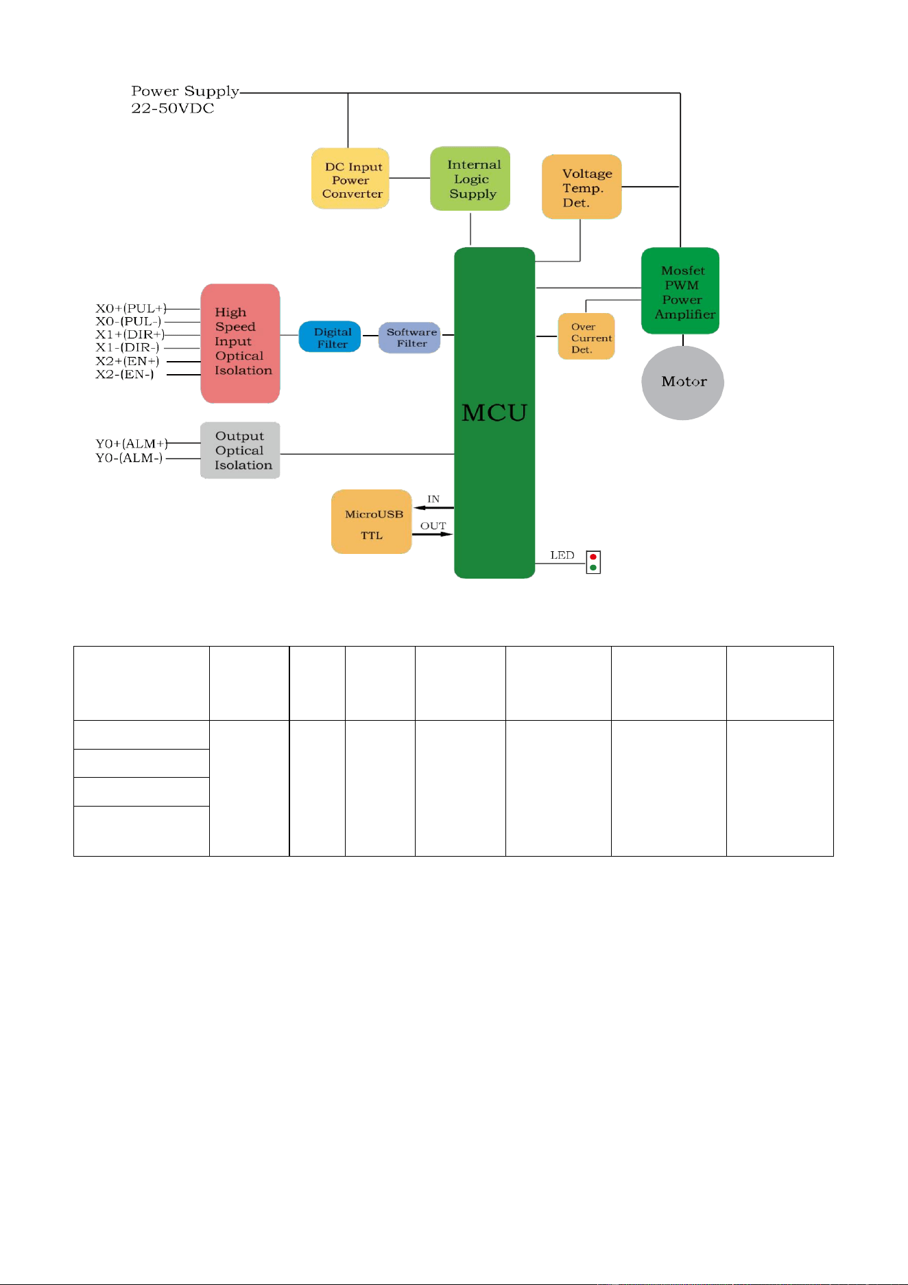
2.Product Structure Block Diagram
3、驱动参数及产品选型
Model
Voltag
e
Curr
ent
Input
Output
Communi
cation
Method
Communic
ation
Interface
Working
Mode
TST60-65P
24-48
VDC
5A
3.3~2
4Vc
omp
atibl
e
Maximu
m
withstan
d voltage
30V50
MA
TTL
MicroUSB
Pulse +
Direction
TST60-86P
TST60-100P
TST60-112P
Model
Body
Length
Shaft Length
Shaft
Diameter
Phase
Current
Phase
Resistance
Phase
Inductance
Holding
Torque
Moment of
Inertia
Weight
mm
mm
mm
A
Ω
mH
N.M
G.cm²
g
TST60-65P
85
21
8
5
0.5
1.5
1.8
280
600
TST60-86P
106
21
8
5
0.4
2.0
2.6
480
800
TST60-100P
120
21
8
5
0.6
2.5
3.5
680
1000
TST60-112P
132
21
8
5
0.7
3.2
4.5
780
1200
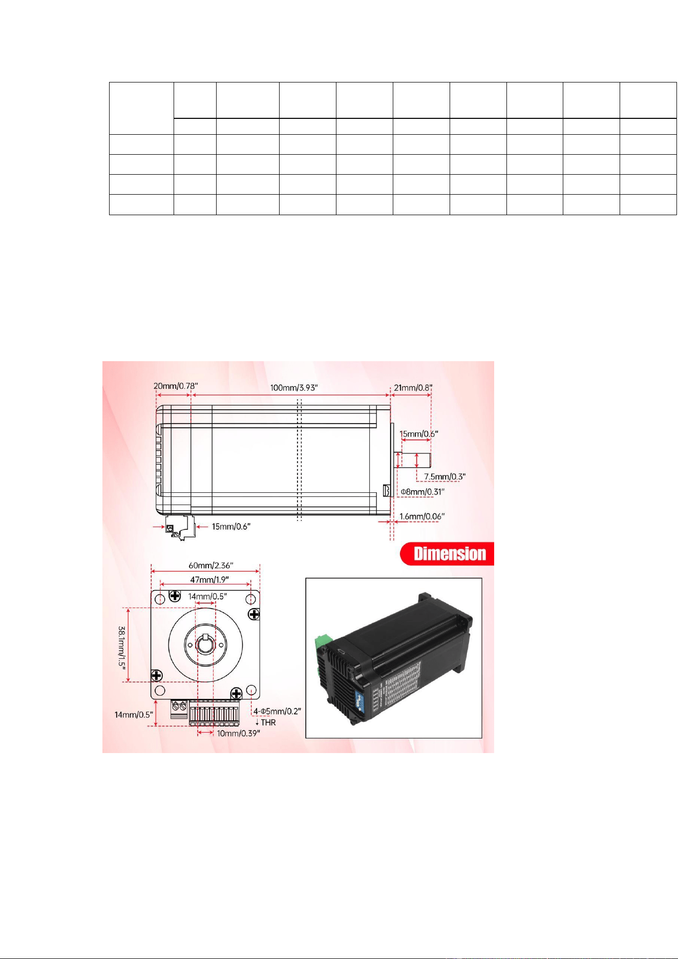
4. Product Schematic and Mechanical
Installation Drawings
5. Preparations Before Start

5.1 You need to prepare the following:
※ A 24~48V DC power supply
※ A personal computer with a Microsoft Windows operating system installed;
※ A matching MicroUSB data cable
5.2 Hardware Installation:
The installation environment of any model of TST60 integrated motor must
have good heat dissipation conditions and air circulation. Sufficient space must
be left around the TST60 integrated motor to ensure air convection.
※ Do not use in an environment without air convection and where the ambient
temperature exceeds 40℃.
※ Do not use in a humid environment.
※ Do not use in an environment that may cause circuit short - circuit.
6. Connecting the Power Supply:
6.1 Selecting the Power Supply Voltage
When selecting a power supply, the most important thing is to reasonably
consider the voltage and current requirements in the actual application. The
TST60 integrated motor performs best when powered by a 36V DC voltage.
The allowable maximum operating voltage range is 22VDC~50VDC. When the
DC voltage supply of TST60 is lower than 24V, it is recommended to connect a
large voltage - stabilizing capacitor in parallel at the power input end to prevent
the driver from low - voltage alarm due to unstable power supply voltage. In
addition, the voltage - stabilizing capacitor can also absorb the current spikes
on the power line to prevent the driver from false protection. When the driver is
powered by a regulated power supply and the supply voltage is close to
50VDC, it is recommended to take voltage clamping measures at the power
input end to avoid the driver from overvoltage alarm and stopping working due
to the supply voltage being higher than 50VDC. When the driver is powered by
an unregulated power supply, please ensure that the no - load output voltage
value of the power supply does not exceed 50VDC.
6.2 Selecting the Power Supply Current
Generally, the input current of the driver power supply is smaller than the
current of the driving motor. This is because the driver itself realizes the power
conversion function, that is, the driver amplifies and converts a high - voltage
low - current signal into a low - voltage high - current signal through a power
switch. The rated voltage of the motor winding is often very small. When the
supply voltage of the driver is higher than the rated voltage of the motor
winding, the input current of the driver power supply is smaller. At the same
time, the magnitude of the power input current is also related to the speed and
load of the motor during operation. Therefore, for specific application scenarios,
users need to carry out specific analysis and estimation.
7. Installation and Wiring:
7.1 Connecting the Power Supply
It is recommended to use AWG20~24 gauge wires to connect the TST60 and
the power supply. Connect the "+" terminal of the power supply to the port
marked "V+" on the TST60, and connect the "-" terminal of the power supply to
the port marked "V-" on the TST60. The TST60 has a fuse connected in series
at the positive input of the power supply internally, but this fuse cannot be
replaced by the user. Users can also connect another 5A fast - blow fuse in
series at the positive pole of the power supply (externally) to achieve
replaceable fuses.
7.2 Inputs and Outputs
7.2 Input and Output
The TST60 integrated stepper motor has 3 high-speed input signals, and can directly
receive 3.3-24V DC level at high level, with a maximum of

Frequency 300KHZ. The following are detailed functional descriptions of these input and
output signals:
X0/PUL available input function pulse input
X1/DIR available input function direction input
● X2/ENABLE input function enables input
The output functions available for YO/ALM include alarm output, universal output, and
factory default alarm output.
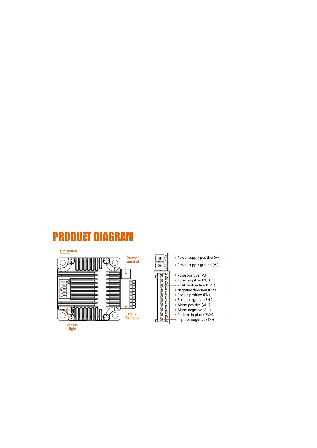
7.3 Connector Pin Definitions
Serial
Number
Name
Function
1
V+
Power supply positive (DC24V~48V)
2
V-
Power supply negative
3
PUL+
Optical isolation, differential, high level can directly
receive 3.3 - 24VDC, minimum pulse width 2us,
maximum pulse frequency 300KHz, default as pulse
input port
4
PUL-
5
DIR+
Optical isolation, differential, high level can directly
receive 3.3 - 24VDC, minimum pulse width 2us,
maximum pulse frequency 300KHz, default as
direction signal input port
6
DIR-
7
EN+
Optical isolation, differential, high level can directly
receive 3.3 - 24VDC, minimum pulse width 100us,
maximum pulse frequency 10KHz, default as
enable input port
8
EN-
9
ALM+
Alarm status output port, which can detect the alarm
status of the motor, normally closed by default, and
output when normal. Can be inverted by software or
set to other functions.
10
ALM-

8. DIP Switch Settings
7.1 Subdivision Settings
Mstep
SW1
SW2
SW3
SW4
400
ON
ON
ON
ON
800
OFF
ON
ON
ON
1600
ON
OFF
ON
ON
3200
OFF
OFF
ON
ON
6400
ON
ON
OFF
ON
12800
OFF
ON
OFF
ON
25600
ON
OFF
OFF
ON
51200
OFF
OFF
OFF
ON
1000
ON
ON
ON
OFF
2000
OFF
ON
ON
OFF
4000
ON
OFF
ON
OFF
5000
OFF
OFF
ON
OFF
8000
ON
ON
OFF
OFF
10000
OFF
ON
OFF
OFF
20000
ON
OFF
OFF
OFF
40000
OFF
OFF
OFF
OFF
8.2 Running Direction Settings

SW5 is used to set the running direction of the motor. When it is OFF, the
motor rotates counterclockwise; when it is ON, the motor rotates clockwise.
9. TTL Communication Parameters
1. Baud rate: default 9600;
2. Data bits: 8 bits;
3. Stop bits: 1 bit;
4. Parity bit: none.
10. Alarm
TST60 uses a dual - color patch LED (red/green) to display the status. The
normal status is that the green LED flashes. If the red LED flashes, it indicates
an alarm or an error has occurred.