FJDynamics
FJDynamics AT2 Lite Auto Steer System
Hardware Installation Manual
FJDynamics AT2 Lite Auto Steer System Hardware Installation Manual
Copyright Notice:
The copyright of this manual is owned by FJDynamics. Reproduction and duplication of
whole or part of the content without permission of the company are strictly prohibited.This
manual is subject to update without notice
Read Before Installation:
Disclaimer
·The purchased products,services,and features are stipulated by the contract.All or part of the
products,services,and features described in this manual may not be within the scope of your
purchase or usage.Unless otherwise specified in the contract,all the content in this manual is
provided "AS IS" without warranties of any kind,express or implied.
·The content of this manual is subject to change due to product upgrades and other reasons.
FJDynamics reserves the right to modify the content of this manua without prior notice.
·This manual only provides guidance for use of this product.Every effort has been made in
the preparation of this manual to ensure accuracy of the content,but no informaton in this
manual constitutes a warranty of any kind,express or implied.
©FJDynamics. All rights reserved.
Follow this manual for installation.
Improper installation may cause machine damage and poor performance.
If you have any questions during installation,contact our customer
service.

FJDynamics AT2 Lite Auto Steer System Hardware Installation Manual
Preface
Thank you for purchasing FJDynamcis product.This manual provides detailed hardware
installation guide.If you have any questions,contact the local
Purpose and Intended Users
This manual introduces the physical characteristics,installation procedures,and technical
specifications of the product as wellas the specifications and use of the wiring harnesses and
connectors.Based on the assumption that the users are familiar with the terms and concepts
related to this product,this manual is intended for users who have read the preceding content
and have experience in hardware installation and maintenance.
Technical Support
·FJDynamics'offical website:https:/www.fjdynamics.com/
·FJDynamics'customer service:service@fjdynamics.com
©FJDynamics. All rights reserved.

FJDynamics
AT2
Lite Auto Steer System Hardware
Installation
Manual
Content
1 Product Introduction..................................................................................................... 1
2 Preparation Before Installation ..................................................................................... 1
2.1 Safety Instructions ................................................................................................... 1
2.2 Installation Requirements .......................................................................................... 2
2.3 Installation Tools ..................................................................................................... 3
2.4 Unpacking and Inspection ......................................................................................... 4
3 Inspection .................................................................................................................. 5
3.1 Inspection Before Installation ........................................................................................ 5
3.2 Precautions ............................................................................................................. 6
4 Installation ................................................................................................................. 6
4.1 Installing the Electric Steering Wheel ............................................................ 6
4.2 Installing the GNSS Receiver ................................................................................... 9
4.3 Installing the Angle Sensor ....................................................................................... 10
4.4 Installing the Radio Antenna .................................................................................. 11
4.5 Installing the Terminal ........................................................................................... 12
4.6 Installing the SIM Card ........................................................................................ 14
4.7 Installing Wiring Harness ........................................................................................ 15
5 System Commissioning ............................................................................................. 16
5.1 Site Requirements ................................................................................................ 16
5.2 Power-on ............................................................................................................. 16
5.3 Parameter Calibration ........................................................................................ 16
6 Appendix .................................................................................................................. 17
6.1 Specifications ......................................................................................................... 17
©FJDynamics. All rights reserved.
FJDynamics AT2 Lite Auto Steer system Hardware Installation Manual
1 Product Introduction
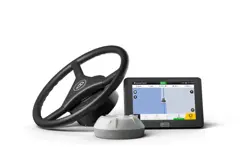
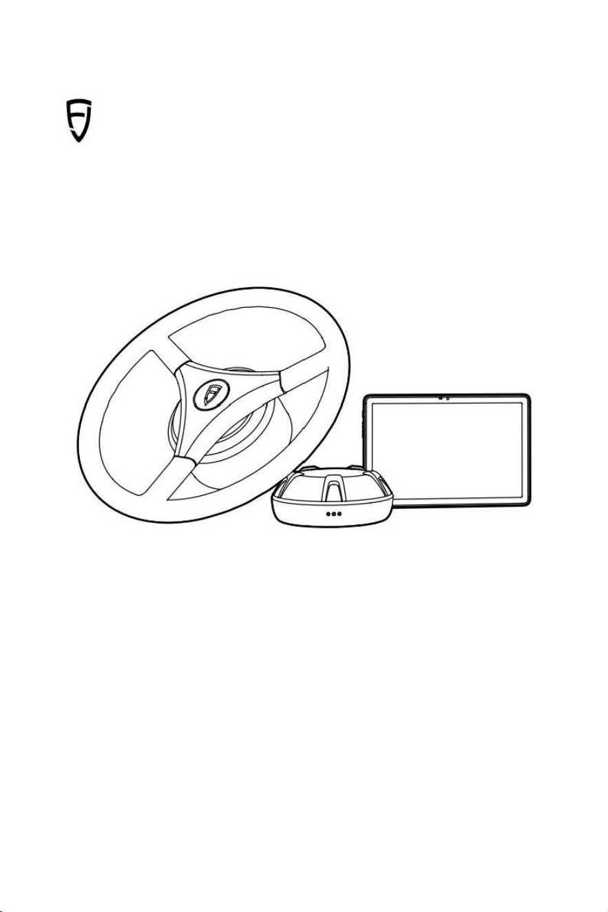
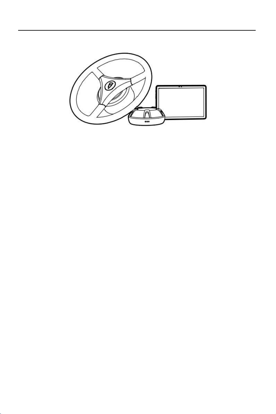
FJ Dynamics AT2 Lite Auto Steer System is an autosteering system that is launched by FJ
Dynamics for agricultural machinery and supports assisted straightline driving.The system
consists of the control terminal,GNSS receiver,electric steering wheel,and wiring harnesses.The
contro terminal runs the software developed by FJ Dynamics.
2 Preparation Before Installation
2.1 Safety Instructions
Before installation,read the safety advice in this manual carefully to avoid doing harm to people
and equipment.
Note that the following safety advice cannot cover allpossible dangerous situations.
2.1.1 Installation
·Do not install and commission the equipment in environments with high temperature,heavy
dust,harmful gases,flammables,explosives,electromagnetic interference(for example,
around large radar stations,transmitting stations,and substations),unstable voltages,great
vibration,and strong noise.
·Do not installthe equipment in places where wateris likely to accumulateseepdrip,and
condense;otherwise,the equipment ports could be damaged.
2.1.2 Disassembly
·To avoid accidental damage,do not frequently disassemble the equipment after installation.
·Before disassembly,turn off all power supplies and disconnect the cable from the battery to
prevent equipment damage.
2.1.3 Electrical Operations
·Electrical operations must be performed by qualified personnel in accordance with local laws
and regulations.
·Carefully check the working area for potential hazardssuch as wet ground.
·Before installation,learn about the position of the emergency stop button.Use this button to
cut off the power supply in case of accidents.
·Do not put the equipment in a humid place.Prevent the liquids from entering the equipment.
1 ©FJDynamics. All rights reserved.

FJDynamics AT2 Lite Auto Steer System Hardware Installation Manual
·Stay away from radio transmitting stations,radar stations,high-frequency and large-current
equipment,and other high-power radio equipment.
·Direct or indirect contact with high voltage or utility power may cause death.
2.2 Installation Requirements
To ensure the norma operation of the equipment,the installation site must meet the following
requirements.
2.2.1 Installation Position
·Ensure that the installation position is firm enough to support the equipment and its accessories.
·Ensure that there is enough space to install the equipment at the installation position,without
any obstruction or obstacle.
2.2.2 Temperature and Humidity
·The temperature and humidity of the working environment should be kept within a reasonable
range to ensure the normal operation and service life of the equipment.Avoid high
temperature and humidity.In summer,protect the control termina from direct sunlight,and
note that appropriate space must be maintained between the shelter and the control terminal.
·The equipment willbe damaged if it works under improper environmental temperature and
humidity.
·When the relative humidity is too hgh,insulating materials may not perform wellcausing
leakage currents.Mechanical property changes,rusting,and corrosion may also occur.
·When the relative humidity is too low,insulating materials will dry and contract,and static
electricity may occur and damage the electric circuits of the equipment.
2.2.3 Air
·Ensure that the contents of salt,acid,and sulfide in the air are within a reasonable range.
Some hazardous substances will accelerate the rusting and corrosion of metals and the aging
of parts.Keep the working environment free of harmful gases(for example,sulfur dioxide,
hydrogen sulfide,nitrogen dioxide,and chlorine).
2.2.4 Power Supply
·Input voltage:The system supports the input voltage of 9-36V.
·Ensure that the power line is connected properly to the positive and negative terminals of the
battery.Keep wiring harnesses away from hot objects.
©FJDynamics. All rights reserved. 2

3 ©FJDynamics. All rights reserved.
FJDynamics AT2 Lite Auto Steer system Hardware Installation Manual
2.3 Installation Tools
Prepare the following tools before installation.
Installation Tools for AT2 Lite Auto Steer System
No.
Tool
Specifications
Qty.
Function
1
Cross screwdriver
PHO*75 small size
1
Install the SIM card.
2
PH2*100 medium size
1
Install the GNSS receiver and
bracket assembly.
3
Allen key
3
1
Install the splined sleeves.
4
5
1
Install the motor bracket and
nameplate bracket.
5
Open-end wrench
8
1
Installthe antenna bracket
assemblies on top of the machine.
6
11
1
Fix the U-bolts of the control
terminal.
7
13
2
Installthe motor bracket.nstall
antenna bracket assemblies.
8
12/14
2
Install the battery cables(bolt size
depends on the machine model)
and motor bracket.
9
18/21
1
Disassemble and install the front
axle shaft cover bolts(bolt size
depends on the machine model).
10
Sleeve
8
1
Install the antenna bracket
assemblies on top of the machine.
11
24/27
1
Installthe GNSS receiver and
antenna bracket assembly.
Disassemble and install the lock nut
of the original steering wheel.
12
Electric drill
1
Work with sleeves.
13
Tweezers
1
Install the SIM card.
14
Ejector pin
1
Install the SIM card.
15
Box cutter
1
Unpack.
16
Scissors
/
1
Cut cable ties.
17
Tape measure
5m
1
Measure vehicle parameters.
18
Open-end wrench
9/10
1
Spare part.

3 ©FJDynamics. All rights reserved.
19
Extra-long
box-end wrench
11/13/14
1
Spare part.

FJDynamics AT2 Lite Auto Steer System Hardware Installation Manual
©FJDynamics. All rights reserved. 4
2.4 Unpacking and Inspection
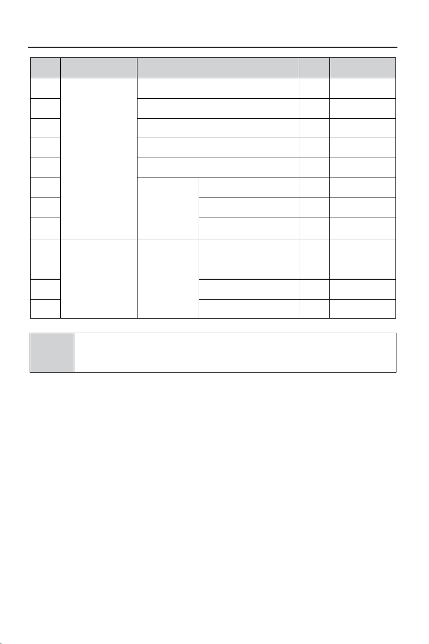
Unpack and check the items according to the following list
No.
Assembly
Component
Qty.
Remarks
1
Electric steering
wheel
Steering wheel
1
2
Steering motor
1
12V/24V
3
Small self-
sealing bag
Hexagon socket head cap
screw M4×14
6
Install splined
sleeves.
4
Spring washer M⁴
6
5
Plain washer M4
6
6
Control terminal
Control terminal
1
7
Control terminal bracket
1
Fix the control
terminal.
8
Control terminal mounting base
1
9
Nut
4
10
U-bolt
2
11
GNSS receiver
GNSS receiver
1
12
Antenna bracket assembly
1
13
Antenna bracket assembly Ⅱ
2
14
3M sticker
1
Fix the GNSS
receiver and
antenna
bracket
assemblies.
15
Small self-
sealing bag 1
Prevailing torque type
hexagon nuts with flange
style 2
4
16
Hexagon bolt 5/8-11
1
17
Spring washer M16
1
18
Plain washer M16
1
19
Small self-
sealing bag 2
Self drilling screw
4
20
Nameplate
bracket
Nameplate bracket
1
With the
nameplate
mounted.
21
Small self-
sealing bag
Hexagon socket head cap
screw M6×16
2
Fix the
nameplate
bracke.
22
Spring washer M6
2
23
Plain washer M6
2
5 ©FJDynamics. All rights reserved.
FJDynamics AT2 Lite Auto Steer
No.
Assembly
Component
Qty.
Remarks
24
Wiring harnesses
Main power cable
1
25
GNSS receiver wiring harness
1
26
Main wiring harness
1
27
Spare main wiring harness
1
28
Angle sensor assembly
1
29
Radio antenna
Sucker base
30
Radio antenna
31
3M sticker
1
Fix the radio
antenna.
32
Others
Large self-
sealing bag
Packing list
1
33
Software user manual
1
34
Certification
1
35
Nylon cable tie
20
!
Note:The splined sleeves,motor bracket,and angle sensor bracket are not
included in the list and will be provided by the dealer separately.The dealer will be
responsible for the installation of such parts based on your machine model.
Above is the general shipping configuration.The actual shipment is subject to the contract and
may differ slightly.Check the items in the package according to the packing list or the contract.If
there is any doubt or discrepancy,contact your dealer.
3 Inspection
Read Chapter 2 carefully,and ensure all requirements specified in this chapter are met before
installation.
3.1 Inspection Before Installation
Before installation,make a detailed plan and arrangement regarding the installation position,
power supplyand wiring of the equipment,and ensure that:
·There is sufficient space to facilitate equipment installation and heat dissipation.
·The environmental temperature and humidity meet the requirements.
·The power supply and wiring meet the requirements.
·The seected power supply matches the system power.
·For a user-specific equipment,ensure that the specific requirements are met.
system Hardware Installation Manual
FJDynamics AT2 Lite Auto Steer System Hardware Installation Manual
©FJDynamics. All rights reserved. 6
3.2 Precautions
·Cut off the power supply when installing the equipment.
·Place the equipment in a dry environment.
·Do not place the equipment in a high-temperature environment
·Keep the equipment away from high-voltage cables.
·Keep the equipment away from strong thunderstorms and electric fields.
·Unplug the power supply before cleaning.
·Do not clean the equipment with liquids.
·Do not open the equipment enclosure.
·Fix the equipment firmly.
4 Installation
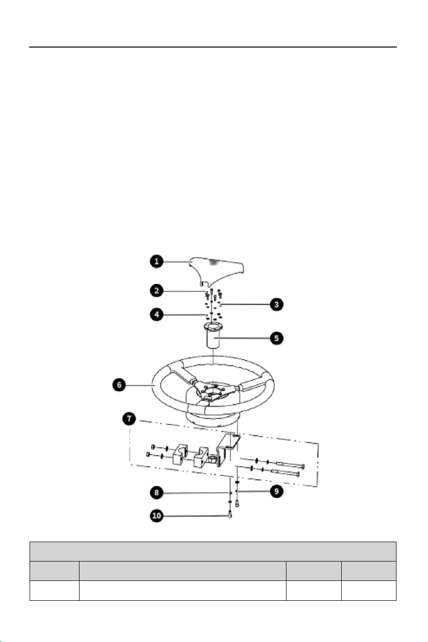
4.1 Installing the Electric Steering Wheel
4.1.1 Components
Electric Steering Wheel Assembly
No.
Name
Qty.
Remarks
1
Dust cap
1

FJDynamics AT2 Lite Auto Steer System Hardware Installation Manual
©FJDynamics. All rights reserved. 6
2
Hexagon socket head cap screw M4×14
6
3
Spring washer M4
6
4
Plain washer M4
6
7 ©FJDynamics. All rights reserved.
FJDynamics AT2 Lite Auto Steer system Hardware Installation Manual
Electric Steering Wheel Assembly
No.
Name
Qty.
Remarks
5
Splined sleeve
1
Packed in the accessory box
and selected according to the
machine model.
6
Electric steering wheel
1
7
4#motor bracket
1
Packed in the accessory box and
shown below.
8
Plain washer M6
2
9
Spring washer M6
2
10
Hexagon socket head cap screw
M6×16
2
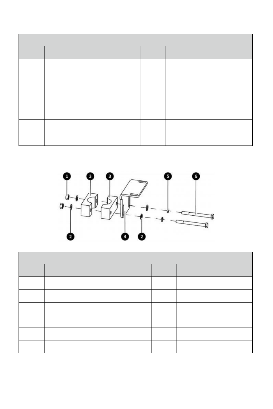
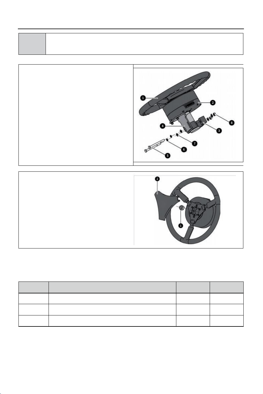
*An example of 2#motor bracket is shown below.
2#Motor Bracket(Component 7 of the Electric Steering Wheel Assembly)
No.
Name
Qty.
Remarks
1
Hexagon nut M8
2
2
Plain washer M8
4
3
Steering column hoop
2
4
Steering motor mounting bracket
1
5
Spring washer M8
2
6
Hexagon bolt M8×80
2
FJDynamics AT2 Lite Auto Steer System Hardware Installation Manual
©FJDynamics. All rights reserved. 8
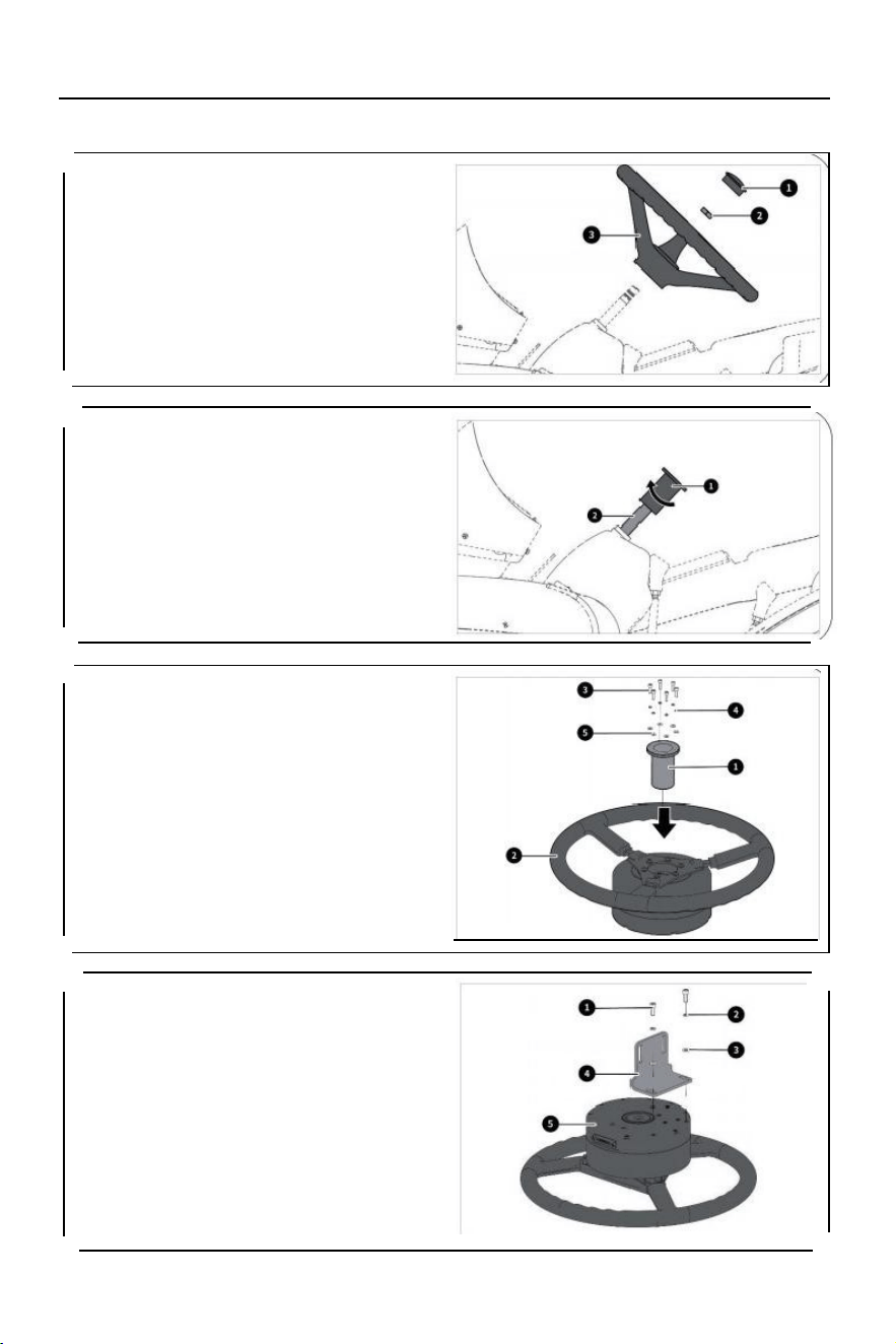
4.1.2 Installation Steps
1.Remove the dusk cap O of the original
steering wheel on the machine,unscrew
the lock nut ② (keep the nut for later use),
and pull out the original steering wheel ③.
2.Install the splined sleeve 0on the steering
column ② ,and check whether the splined
sleeve is appropriate by rotating it to see
whether there are any sways or gaps.As
the steering column on the machine varies,
you may try several splined sleeves to
select the one that fits.
3.Remove the selected splined sleeve 0from
the steering column,put it into the steering
motor of the electric steering wheel ②, and
then fix the splined sleeve and the motor
with six M4×14 hexagon socket head cap
screws ③,six M4 spring washers ④and six
M4 plain washers ⑤.
4.Fix the steering motor ⑤and motor bracket
④with two M6×16 hexagon socket head
cap screws 0 ,two M6 spring washers ②,
and two M6 plain washers ③.Do not fully
torque the screws at this time.
FJDynamics AT2 Lite Auto Steer system Hardware Installation Manual
!
Note:As the dashboard under the steering wheel varies,select an appropriate
motor bracket according to the specific machine used.The 2#motor bracket is only
shown and illustrated as an example.
5.Installthe electric steering wheel 0 on
the machine,and adjust the position of
the motor port ② to facilitate the wiring
harness connection (it is recommended
to adjust it to the position convenient for
connection with the control terminal).
Install the steering column hoop ③, adjust
the position of the motor bracket ④,and
tightenit with two M8×80 hexagon bolts
⑤,two M8 spring washers ⑥,two M8 plain
washers ⑦, and two M8 hexagon nuts 8
to ensure that the motor bracket is firmly
installed and the outer ring does not rotate
with the bracket.
6.Install the lock nut ① removed in step1
on the splined sleeve and installthe dust
cap② .
4.2 Installing the GNSS Receiver
4.2.1 Components
No.
Name
Qty.
Remarks
1
GNSS receiver Antenna bracket assembly
1
2
DovetailNail
4
3
3M sticker
2
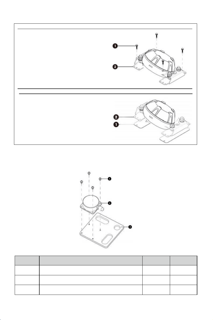
4.2.2 Installation Steps
1.The GNSS receiver can be fixed on the top of the agricultural machinery by using dovetail nails
or 3M double-sided tape.Choose the appropriate installation method according to the actual
situation of the top of the agricultural machinery.
9 ©FJDynamics. All rights reserved.
FJDynamics AT2 Lite Auto Steer System Hardware Installation Manual
©FJDynamics. All rights reserved. 10
Method 1:Fix the four corners of the
GNSS receiver bracket 2 to the top of the
agricultural machinery using dovetailnails O.
Method 2:Use 3M double-sided tape 2 to
stick and fix the GNSS receiver bracket 0.
4.3 Installing the Angle Sensor
4.3.1 Components
No.
Name
Qty.
Remarks
1
Assembly bolt M3×8
4
2
Angle sensor
1
3
Angle sensor bracket
1
1I ©FJDynamics. All rights reserved.
FJDynamics AT2 Lite Auto Steer system Hardware Installation Manual
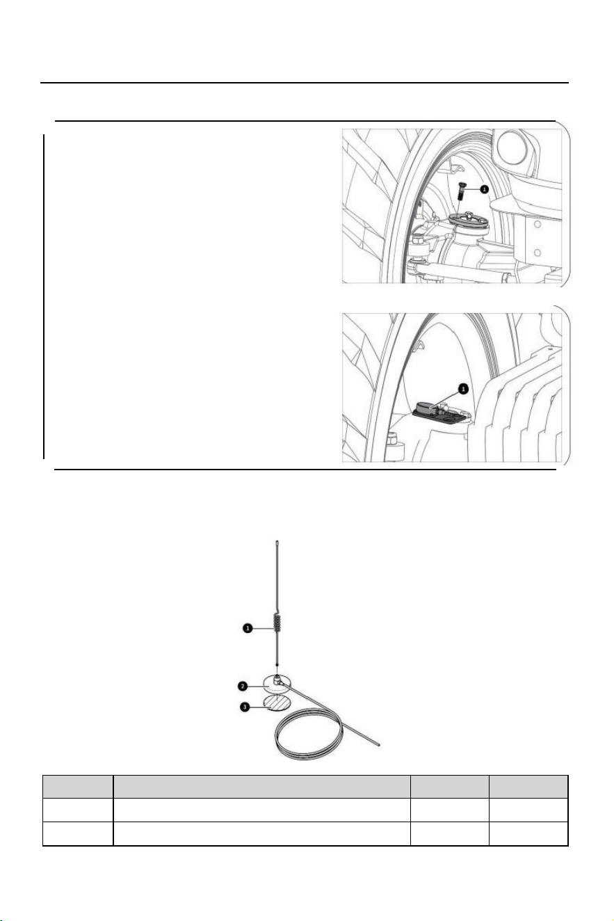
4.3.2 Installation Steps
1.Remove the front axle shaft cover bolts 0.
2.Install the angle sensor 0on the front axle,
adjust the wiring harness,and install and
tighten the bolt removed in step 1.
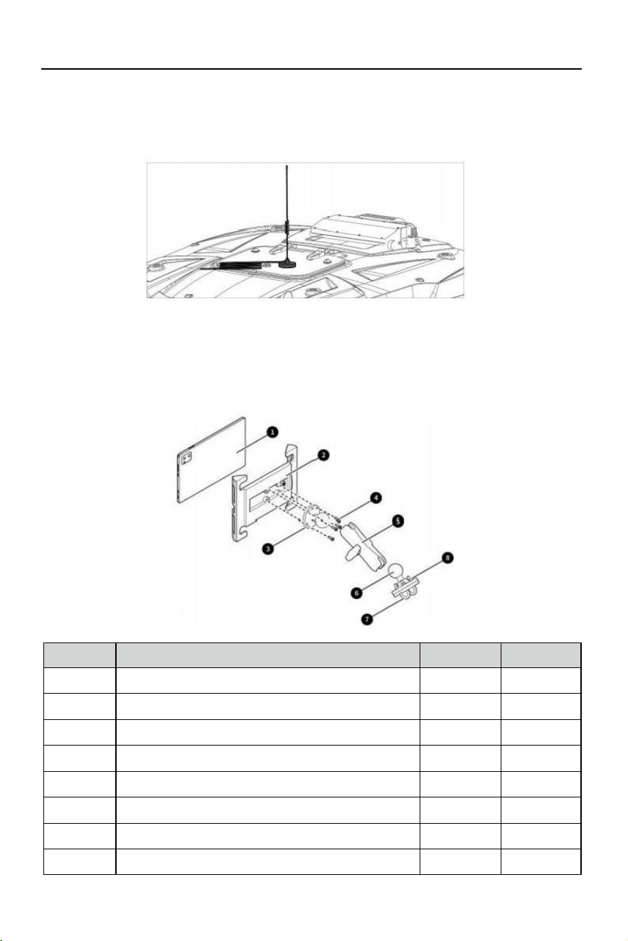
4.4 Installing the Radio Antenna
4.4.1 Components
No.
Name
Qty.
Remarks
1
Radio antenna
1
2
Sucker base
1

1I ©FJDynamics. All rights reserved.
3
3M sticker
1
FJDynamics AT2 Lite Auto Steer System Hardware Installation Manual
©FJDynamics. All rights reserved. 12
4.4.2 Installation Steps
·If there is no suitable metal plane on top of the machine,select and clean a suitable plane to
install the antenna.Attach the 3M sticker on the sucker base of the radio antenna,and attach
the antenna to the selected position.
·If there is a suitable metal plane on top of the machine,wipe the plane clean,and then directly
suck the radio antenna to the plane.
4.5 Installing the Terminal
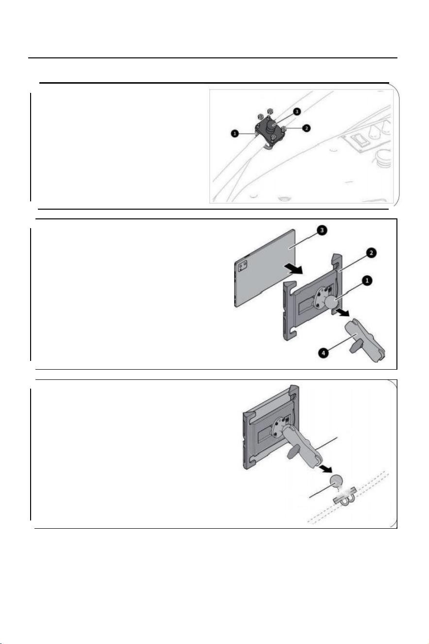
4.5.1 Components
No.
Name
Qty.
Remarks
1
Control Terminal assembly
1
2
Control Terminal Bracket
1
3
Control Terminal bracket connectorl
1
4
Screw
4
5
Bracket fixing rod
1
6
Control Terminal bracket connector2
1
7
U-bolt
2
8
Nuts
4
13 CFJDynamics.All rights reserved.
FJDynamics AT2 Lite Auto Steer system Hardware Installation Manual
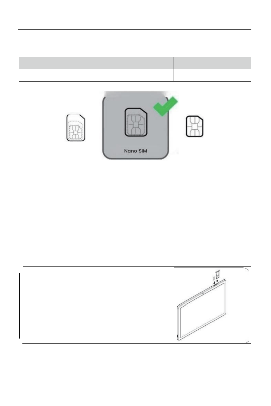
4.5.2 Installation Steps
Step 2:Fix the connection base 0 to the
back of the tablet terminal bracket ② with
screws,put the tablet terminal ③ in and
fix it,rotate the handle of the fixing rod ④
counterclockwise to loosen the left and right
sides.Connect the tablet terminal to the
upper ballsocket of the fixing rod through the
back ballhead.
Step 3:Installthe tablet terminal and the
fixing rod O connected in step 2 into the
ball ②of the connection base in the same
way.After confirming the position,rotate the
fixing rod handle clockwise to ensure that the
tablet terminal is fixed and does not shake.
Step 1:Select a position on the door
armrest on the side of the cab joystick
that is easy for personnel to operate,and
use 2 U-bolts 0 and 4 nuts ② to fix the
connection base 3.
FJDynamics AT2 Lite Auto Steer System Hardware Installation Manual
4.6 Installing the Terminal
4.6.1 Components
No.
Name
Qty.
Remarks
1
SIM card
1
Nano SIM
Mini SIM
Micro-SIM
Notes:
1.Purchase a SIM card that supports the frequency bands of the 4G communication module of
the control terminal.
2.Ensure that the SIM card supports the following 4G frequency bands:
LTE-FDD:B1/B2/B3/B4/B5/B7/B8/B20/B28
LTE-TDD:B38/B39/B40/B41
GSM:B3/B5/B8
3.Ensure that you have data service with your SIM card.
4.After installing the SIM card,turn on the control terminal and set the APN and network type in
the Android system settings if it is required according to the SIM card manual.
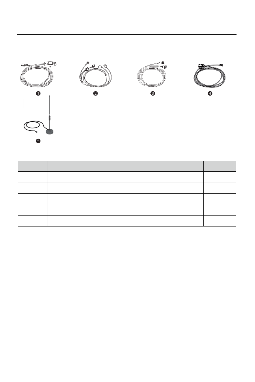
4.6.2 Installation Steps
1.Find the SIM card slot on the side of the
tablet terminal,carefully insert the SIM card
needle into the small hole in the SIM card
slot,and apply slight pressure until the SIM
card tray pops out.
2.Take out the SIM card tray,align the SIM card with the card slot,make sure the metal contact
point of the SIM card is in the correct direction and matches the shape of the slot,and gently
put the SIM card into the slot,making sure it is completely flat and not loose.
3.Gently push the SIM card tray back into the slot,making sure the edge of the tray is flush with
the tablet case.
©FJDynamics. All rights reserved. 14
15 ©FJDynamics. All rights reserved.
FJDynamics AT2 Lite Auto Steer system Hardware Installation Manual
4.7 Installing Wiring Harness
4.7.1 Components
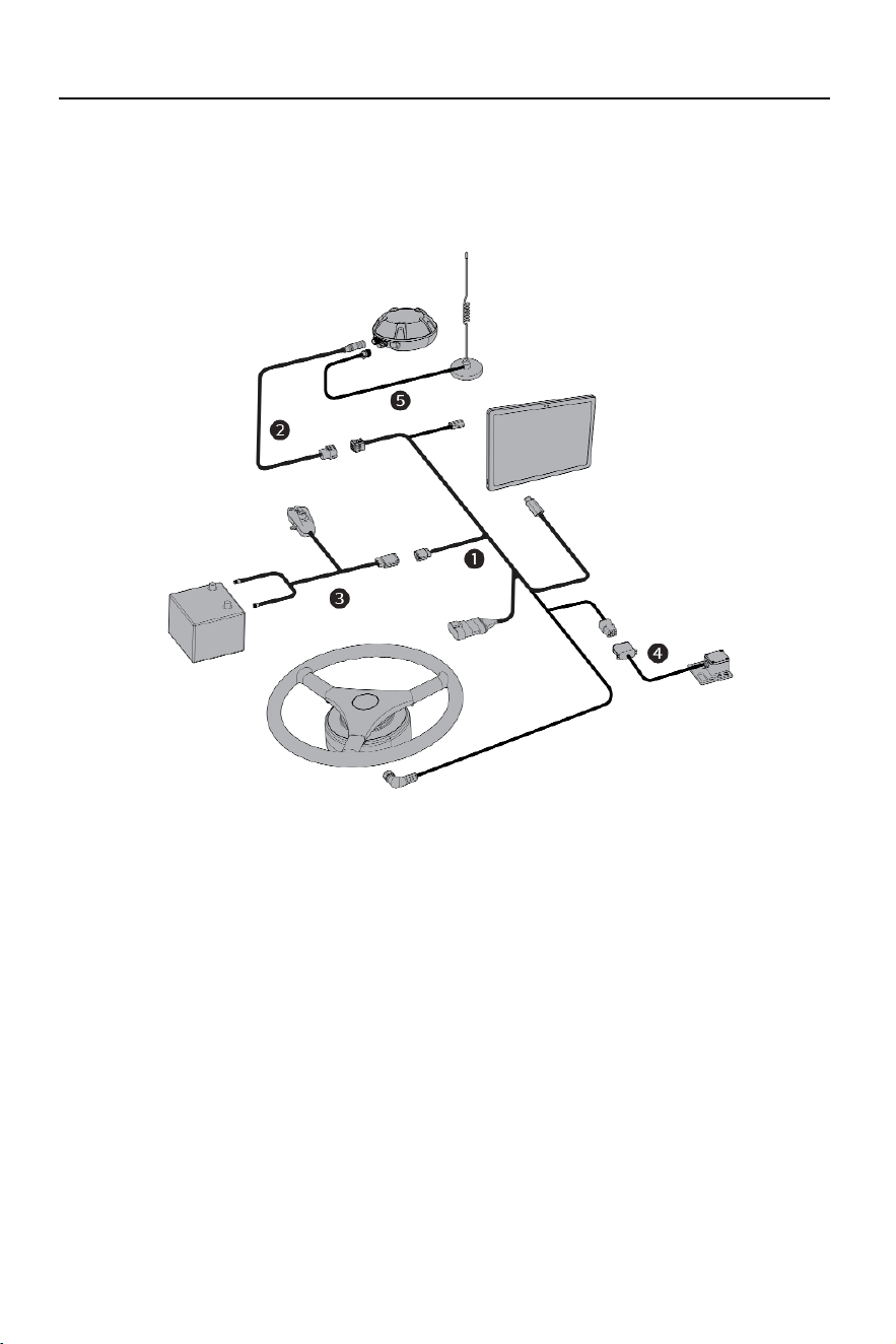
No.
Name
Qty.
Remarks
1
Main Wiring Harness
1
2
GNSS receiver wiring harness
1
3
Main Power Cable
1
4
Angle Sensor Assembly
1
5
Radio antenna
1
4.7.2 Installation Steps
Install the wiring harnesses according to the figure below.
Notes:
1.Do not plug or unplug the harness connectors or connect equipment when the power is on.
Ensure that the machine and the battery are turned off.
2.Avoid high temperature and rugged places when wiring.
3.Connect the power wiring harness to the negative terminal first,and then connect it to the
positive terminal and other wirng harnesses.
4.Keep the radio antenna away from the GNSS receiver,and ensure that it is firmly sucked and
unobstructed.
Installation Tips:
1.Main/spare wiring harness:Lock the door on the right side of the cab,and then sort out the
wiring harness and fixit on the right door handle or the A-pillar at the right front of the cab
with nylon cable ties
2.GNSS receiver wiring harness:Extend the wiring harness from the roof(such as the sunroof)
along the cab to the right front of the seat.
3.Main power cable:Connect the negative connector of the wiring harness to the negative

15 ©FJDynamics. All rights reserved.
terminal of the batteryand do not connect the positive connector of the wiring harness at
this time.Fix the wiring harness along the right side of the machine with nylon cable ties,and
connect it into the cab from the rightfront of the cab.
FJDynamics AT2 Lite Auto Steer System Hardware Installation Manual
©FJDynamics. All rights reserved. 16
4.Angle sensor assembly:Leave 10 cm of the wiring harness at the sensor side,fix the wiring
harness along one side of the machine with nylon cable ties,and connect it into the cabfrom
the front of the cab.
5. Radio antenna:Route the wiring harness in the same direction as that of the GNSS
receiver, and keep the antenna away from the receiver.
5 System Commissioning
5.1 Site Requirements
1.Ensure that the vehicle is in good condition and all parts work properly
2.Ensure that there are no tall trees,buildings,or other obstacles around the site to protect the
operation from signal interference.
3.Ensure that there are no high-voltage power lines within 150 m around the site.
4.The site ground should be level and no smaller than 50 m×10 m.
5.The site should have flat concrete pavement or asphalt pavement.
6.Commissioning should be carried out on non-public roads.Ensure that no irrelevant personnel
stay around the vehicle during commissioning to prevent accidents
5.2 Power-on
5.2.1 Inspection Before Power-on
1.Check whether the power supply is connected correctly.

FJDynamics AT2 Lite Auto Steer System Hardware Installation Manual
©FJDynamics. All rights reserved. 16
2.Check whether the supply voltage is satisfactory.
5.2.2 Inspection After Power-on
1.Check whether the power indicator of the control terminal is lit
2.Turn on the contro terminal,and check whether the system program starts normally
5.3 Parameter Calibration
For details,refer to the FJDynamics AT2 Lite Auto Steer System Software User Manual.
17 CFJDynamics.All rights reserved.
FJDynamics AT2 Lite Auto Steer system Hardware Installation Manual
6 Appendix
6.1 Specifications
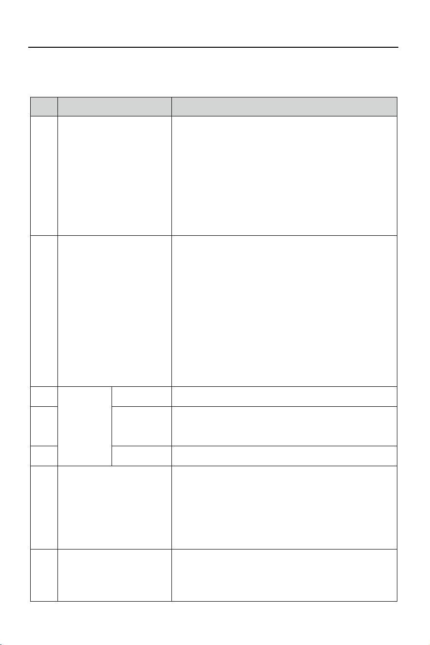
No.
Component
Specifications
1
Control terminal
Size:251x170x17(mm);
Screen:10-inch
Resolution:1280*800,
RAM:4GB
ROM:64GB
Supply voltage:5V/3A DC;
Signals received:4G signal.
Operating temperature:-10℃ to 45℃
Storage temperature:-20℃ to 70℃
Wireless communication:2.4GHzWi-Fi,BT5.0
2
GNSS receiver
Size:162 mm×64.5mm
External interface:TNC dual antenna extension×1,
Type-C debug port×1
Frequency band:GPS LI/L2;GLONASS LI/L2;BDS BI/B2l;
Galileo E1/E5b
Operating voltage:9V-36V
operating current:<300 mA
IMU accelerometer accuracy:0.5 mg
IMU gyroscope accuracy:0.10/s
Rol/pitch:0.2°
Operating temperature:-20℃ to 70℃
Storage temperature:-40℃ to 85℃
IP rating:IP67
3
Electric
steering
wheel
Steering wheel
Diameter:410 mm
4
Steering motor
Supply voltage:12 V or 24V
Peak torque:15 Nm(12V);20 Nm(24V)
IP rating:IP65
5
Splined sleeve
Multiple sizes
6
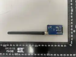
Radio antenna
Frequency range:410 MHz-470 MHz
Voltage standing wave ratio:≤2.0
Gain:l±0.5 dBi
Impedance:50Ω
Polarization:vertical
Size:082 mm×490 mm
operating temperature:-20℃ to 60℃
7
Angle sensor
Supply voltage:12V Output frequency:max.200
Hz
Resolution:<0.1° Operating temperature:-20℃ to 85℃
IP rating:IP67

17 CFJDynamics.All rights reserved.
This device contains licence-exempt transmitter(s)/receiver(s) that
comply with Innovation, Science and Economic Development Canada’s
licence-exempt RSS(s). Operation is subject to the following two
conditions:
(1) This device may not cause interference.
(2) This device must accept any interference, including interference that
may cause undesired operation of the device.
L’émetteur/récepteur exempt de licence contenu dans le présent
appareil est conforme aux CNR d’Innovation, Sciences et
Développement économique Canada applicables aux appareils radio
exempts de licence. L’exploitation est autorisée aux deux conditions
suivantes:
(1) L' appareil ne doit pas produire de brouillage;
(2) L' appareil doit accepter tout brouillage radioélectrique subi, même si
le brouillage est susceptible d' en compromettre le fonctionnement.
conditions d'exposition portables.
ISED Radio Frequency Exposure Statement:
This equipment complies with ISED exposure limits set forth for an
uncontrolled environment. This equipment shall be installed and operated
with minimum distance 20cm between the radiator & body.
Déclaration d'ISDE sur l'exposition aux radiofréquences :
Cet équipement est conforme aux limites d'exposition d'ISDE établies
pour un environnement non contrôlé. Cet équipement doit être installé et
utilisé à une distance minimale de 20 cm entre le radiateur et le corps.
Operation of this device is restricted to indoor use only. (5150-5350MHz)
Le fonctionnement de cet appareil est limité à une utilisation en intérieur
uniquement. (5150-5350MHz)
For Canada: The frequency stability of all transmission frequencies of U-
NII-1, U-NII 2A and U-NII-3 meets the requirements of RSS-Gen Issue 5,
Section 6.11, and the manufacturer states that their transmissions remain
within the U-NII-1, U-NII 2A and U-NII-3 bands.
Pour le Canada : La stabilité de fréquence de toutes les fréquences de
transmission U-NII-1, U-NII 2A et U-NII-3 répond aux exigences de la
norme CNR-Gen, édition 5, section 6.11, et le fabricant déclare que leurs
transmissions restent dans les bandes U-NII-1, U-NII 2A et U-NII-3.

17 CFJDynamics.All rights reserved.
This device complies with Part 15 of the FCC Rules. Operation is subject
to the following two conditions:
1)This device may not cause harmful interference, and
2)this device must accept any interference received, including
interference that may cause undesired operation.
15.105 Information to the user.
NOTE: This equipment has been tested and found to comply with the
limits for a Class B digital device, pursuant to part 15 of the FCC Rules.
These limits are designed to provide reasonable protection against
harmful interference in a residential installation. This equipment
generates, uses and can radiate radio frequency energy and, if not
installed and used in accordance with the instructions, may cause
harmful interference to radio communications. However, there is no
guarantee that interference will not occur in a particular installation. If this
equipment does cause harmful interference to radio or television
reception, which can be determined by turning the equipment off and on,
the user is encouraged to try to correct the interference by one or more of
the following measures:
Reorient or relocate the receiving antenna.
Increase the separation between the equipment and receiver.
Connect the equipment into an outlet on a circuit different from that
to which the receiver is connected.
Consult the dealer or an experienced radio/TV technician for help.
Changes or modifications not expressly approved by the party
responsible for compliance could void the user's authority to operate the
equipment.
FCC RF Exposure Warning Statement:
This equipment complies with FCC radiation exposure limits set forth for
an uncontrolled environment. This equipment shall be installed and
operated with minimum distance 20cm between the radiator & body.
For USA: The frequency stability of all transmission frequencies of U-NII-
1, U-NII 2A and U-NII-3 meets the requirements of 47 CFR FCC
Part15.407(g), and the manufacturer declares that their transmission is
maintained at Band U-NII-1, U-NII 2A and U-NII-3.