
Rainbow Dynamics Inc
8314 Sherwick Ct, Jessup, MD 20794, United States
QCG18F30 User Manual
General
QCG18F30 is a highly integrated, cost-eecve, high-power 16-channel full-duplex data
transmission module. It features a built-in high-speed micro-controller, high-performance
RF transceiver chip, and RF power amplier. The module provides a standard serial port
for communicaon, enabling easy and quick parameter sengs and control of the
transmit/receive funcons. Users can achieve data transmission simply by connecng the
module to the serial port. Its ultra-compact size allows for easy and fast integraon into
various handheld devices, enhancing the overall performance of terminal products,
making this module widely applicable.
QCG18F30 is a 16-way full-duplex wireless data communicaon module that can achieve
up to 16 transmiers transming simultaneously without interfering with each other. It
is designed for scenarios where mulple transmiers operate concurrently in complex
environments, minimizing the likelihood of re-transmissions and signicantly reducing
interference and the chances of being interfered with. The combinaon of LoRa
modulaon with 1W output power, along with its low-power design for receiving and
sleep modes, makes it ideal for long-distance wireless IoT applicaons.
2
Parameters List
Power supply: 3.3V DC
Frequency band: 902.125-917.125MHz
Channel Number: 16
Channel Separaon: 1MHz
Modulaon: LoRa
Max. peak power: 27.90[email protected]
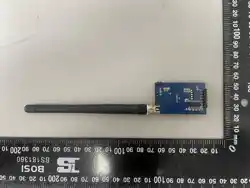
Antenna: Permanently aached folding rod antenna, 2.15dBi
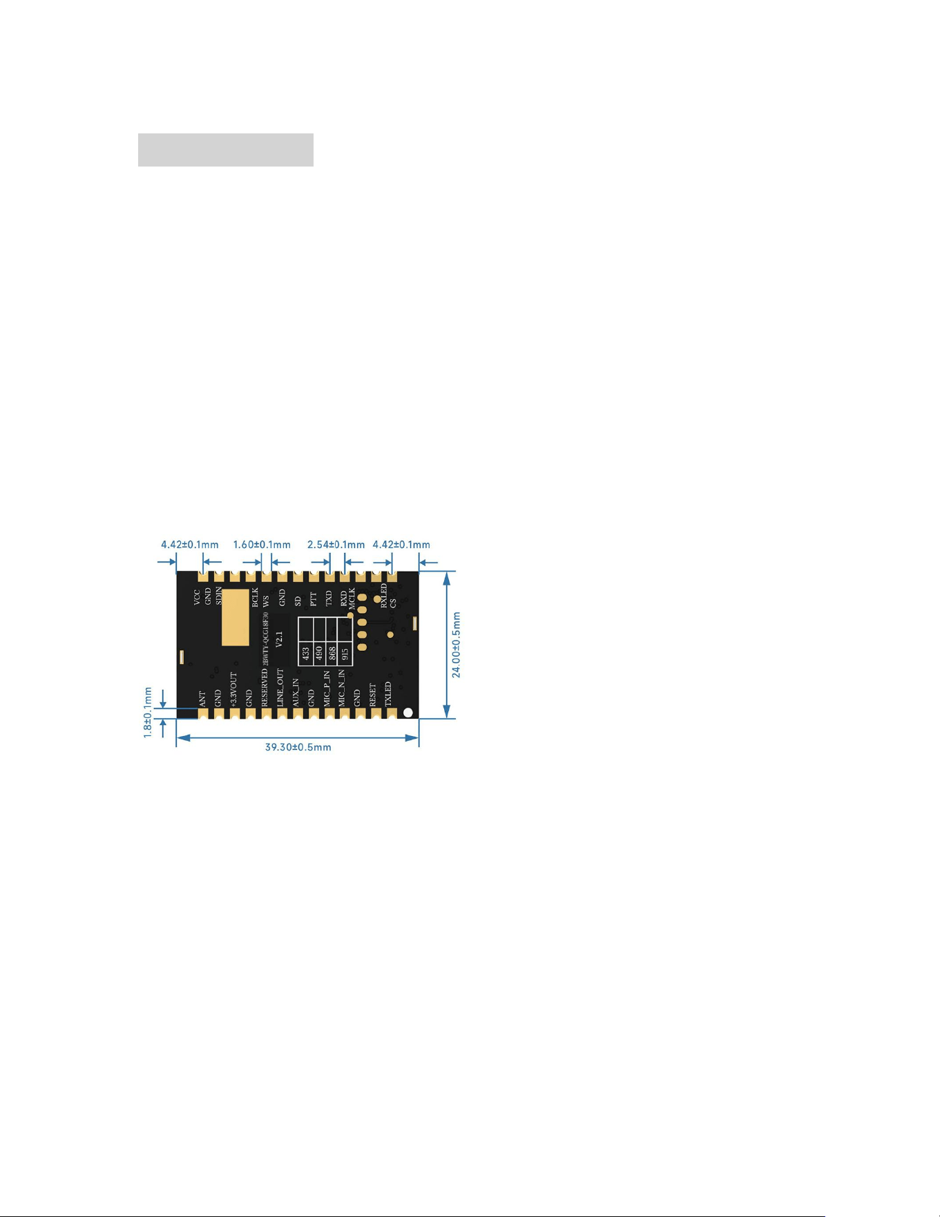
Module Dimensions:
3
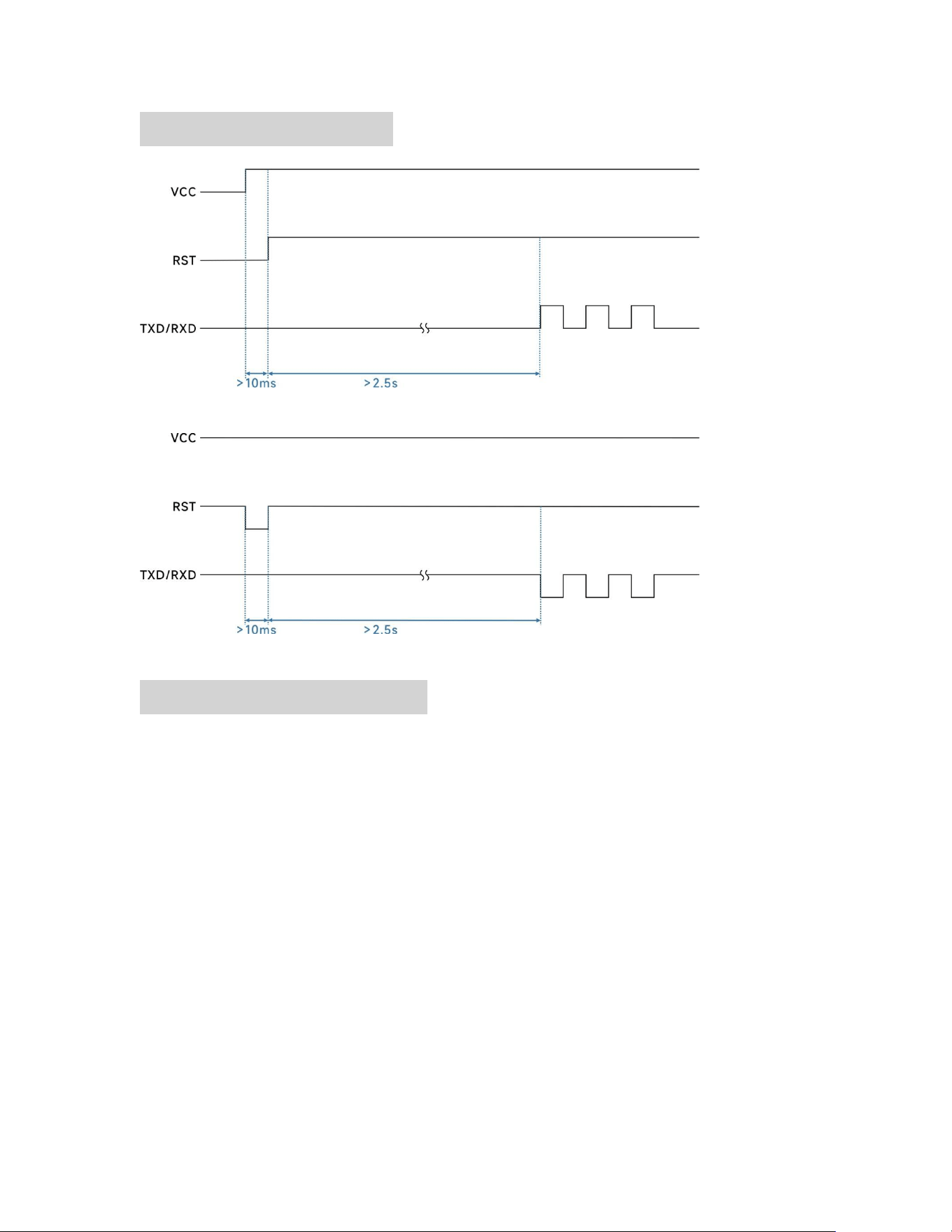
Reset Timing Diagram
Power-on Reset Timing Diagram
Operang State Reset Timing Diagram
Communicaon protocol
The module provides a user-friendly interface (standard serial port), allowing users to
send commands via the serial port to control the module and read its parameters.
4
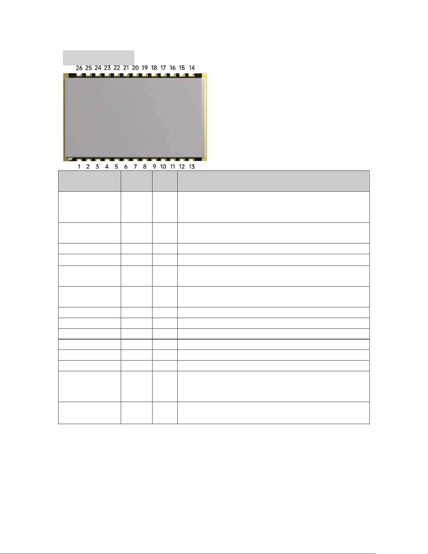
Pin Denion
Pin NO.
Pin
name
I/O
Descripon
1
TXLED
O
Transming indicator, connected with external led,
turn on by low level output when data is transming
, (suggest 1K ohm resistor for current limitaon)
2
RESET
I
Module reset pin: Pulling it low for more than
5 ms will reset the module
3,6,10,12,15,19
GND
Connect to the power supply ground
4,5,7,8
NC
9
RESER
VED
Module test pin: Leave unconnected (oang)
for users
11
+3.3V
OUT
3.3V output, capable of driving an external load
of up to 50mA
13
ANT
RF signal output, connect to a 50-ohm antenna
14
VCC
Connect to the posive power supply
16,17,18,20,21
NC
22
TXD
O
Module serial port transmit pin
23
RXD
I
Module serial port receive pin
24
NC
25
RXLED
O
External receive indicator light: Lights up on low level,
normal high level output (requires an external
current-liming resistor of approximately 1K ohms)
26
CS
I
Module sleep pin: High level for operaon, low level
for sleep.Internally pulled up, defaults to high level。

5
FCC regulatory compliance statement
This device complies with part 15 of the FCC Rules. Operaon is subject to the following
two condions: (1) This device may not cause harmful interference, and (2) this device
must accept any interference received, including interference that may cause undesired
operaon.
Cauon: Changes or modicaons to this unit not expressly approved by the party
responsible for compliance could void the user's authority to operate the equipment.
This Module complies with FCC radiaon exposure limits set forth for an uncontrolled
environment. This equipment should be installed and operated with a minimum distance
of 20cm between the radiator and your body. This transmier must not be co-located or
operang in conjuncon with any other antenna or transmier.
Labelling Instrucon for Host Product Integrator
Please noce that if the FCC idencaon number is not visible when the module is
installed inside another device, then the outside of the device into which the module is
installed must also display a label referring to the enclosed module. This exterior label can
use wording such as the following: “Contains FCC ID: 2BWYT-QCG18F30” any similar
wording that expresses the same meaning may be used.
Installaon Noce to Host Product Manufacturer
The OEM integrator is responsible for ensuring that the end-user has no manual
instrucon to remove or install module.
The module is limited to installaon in mobile applicaon, a separate approval is required
for all other operang conguraons, including portable conguraons with respect to
§2.1093 and dierence antenna conguraons.
Antenna Change Noce to Host manufacturer
If you desire to increase antenna gain and either change antenna type or use same
antenna type cered, a Class II permissive change applicaon is required to be led by
us, or you (host manufacturer) can take responsibility through the change in FCC ID (new
applicaon) procedure followed by a Class II permissive change applicaon.
FCC other Parts, Part 15B Compliance Requirements for Host product manufacturer
This modular transmier is only FCC authorized for the specic rule parts listed on our
grant, host product manufacturer is responsible for compliance to any other FCC rules that
apply to the host not covered by the modular transmier grant of cercaon.

6
Host manufacturer in any case shall ensure host product which is installed and operang
with the module is in compliant with Part 15B requirements.
This equipment has been tested and found to comply with the limits for a Class B digital
device, pursuant to part 15 of the FCC Rules. These limits are designed to provide
reasonable protecon against harmful interference in a residenal installaon. This
equipment generates, uses and can radiate radio frequency energy and, if not installed
and used in accordance with the instrucons, may cause harmful interference to radio
communicaons. However, there is no guarantee that interference will not occur in a
parcular installaon. If this equipment does cause harmful interference to radio or
television recepon, which can be determined by turning the equipment o and on, the
user is encouraged to try to correct the interference by one or more of the following
measures:
—Reorient or relocate the receiving antenna.
—Increase the separaon between the equipment and receiver.
—Connect the equipment into an outlet on a circuit dierent from that to which the
receiver is connected.
—Consult the dealer or an experienced radio/TV technician for help.

7
The compliance of KDB 996369 D02 Module Q&A v02 Queson 11:
Not Applicable – This module does not employ a trace antenna design.
The requirement for KDB 996369 D03:
1. List of. Applicable FCC Rules
This modular transmier complies with the FCC rules: 47 CFR Part 15.247.
2. Summarize the Specic Operaonal Use Condions
EUT use folding rod antenna.
3. Limited Module Procedures
Not Applicable – The module is a single module.
4. Trace Antenna Designs
Not Applicable – This module does not employ a trace antenna design.
5. RF Exposure Consideraons
The module is installed to always maintain a minimum separaon distance of at least 20
cm between the antenna and any person’s body.
6. Antennas
The following antennas have been approved for use with this module:
Permanently aached folding rod antenna, Maximum Gain: 2.15 dBi
7. Label and Compliance Informaon
If this cered module is installed inside the host device, then the outside of the host
must be labeled with “Contains FCC ID: 2BWYT-QCG18F30
8. Informaon on Test Modes and Addional Tesng Requirements
The host manufacturer can use soware to make the transmission connuously.
9. Addional Tesng, Part 15 Subpart B Disclaimer
The module complies with the FCC Part 15.247. If the module is installed in the host device,
the host manufacturer is responsible for the compliance to any other FCC rules that apply
to the host not covered by the modular transmier grant of cercaon. For example, if
the host manufacturer markets their product as being Part 15 Subpart B compliant (when
it also contains unintenonal-radiator digital circuity), then the host manufacturer shall
provide a noce stang that the nal host product sll requires Part 15 Subpart B
compliance tesng with the modular transmier installed.
8
DECLARATION OF COMPLIANCE
Since only the Grantee (module manufacturer) is permied to le permissive
changes with the FCC, any changes to the module's use condions require coordinaon
with the Grantee. If you intend to use this module dierently than granted, please contact:
Company
Rainbow Dynamics Inc
Contact Person
Nan Zhang
Email
Susan.zhang@rainbow-dynamics.ai
The OEM integrator acknowledges that they have read and understood these integraon
instrucons and agrees to:
1. Follow all integraon instrucons provided herein;
2. Perform the mandatory test plan per Secon 2.11 for each specic host;
3. Ensure the nal host product complies with all applicable FCC rules;
4. Ax the required label ("Contains FCC ID: 2BWYT-QCG18F30") on the nal product;
5. Not distribute these integraon instrucons to end users;
6. Not integrate the module into any host device without prior Grantee approval and,
if required, a Class II Permissive Change.
***End of User Manual***