1BLACKSTONEPRODUCTS.COM/SUPPORT
6228 • 6430 | OWNER’S MANUAL
ENGLISH
SAFETY ALERT KEY
⚠ Caution
Indicates a hazardous situation that, if not avoided, could result in
minor or moderate injury.
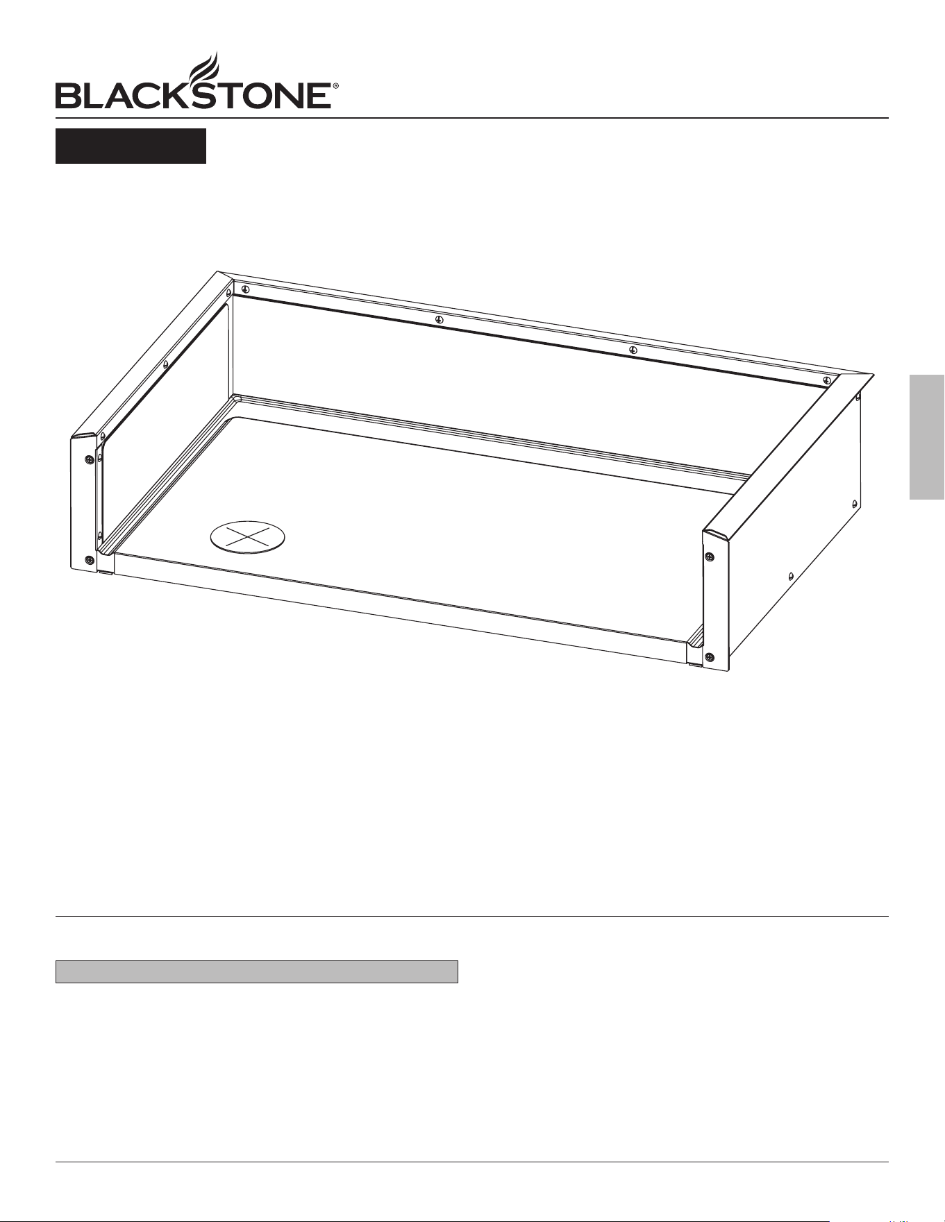
OWNER’S MANUAL
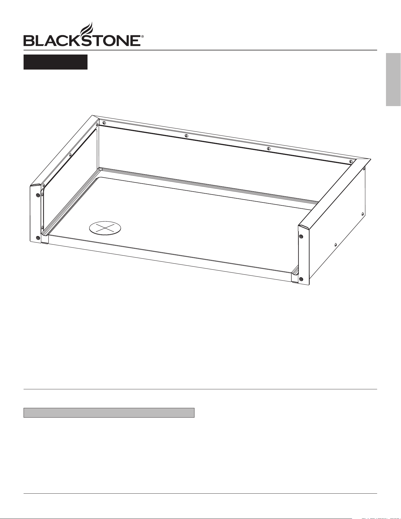
INSULATING JACKET
FOR DROP-IN GRIDDLES
6228 • 6430
v04
DISTRIBUTED BY NORTH ATLANTIC IMPORTS, LLC 1073 W 1700 N LOGAN, UT 84321 USA
BLACKSTONE IS A REGISTERED TRADEMARK OF NORTH ATLANTIC IMPORTS, LLC
©2024 NORTH ATLANTIC IMPORTS. ALL RIGHTS RESERVED.
THIS PRODUCT MAY BE COVERED BY ONE OR MORE ISSUED U.S. AND/OR
INTERNATIONAL PATENTS AND MAY INCLUDE PATENT APPLICATIONS PENDING.
FOR MORE INFORMATION, PLEASE VISIT: BLACKSTONEPRODUCTS.COM/PATENTS
BlackstoneProducts.com/support
CONTACT CUSTOMER SUPPORT BEFORE RETURNING APPLIANCE TO RETAILER.
2 BLACKSTONEPRODUCTS.COM/SUPPORT
6228 • 6430 | OWNER’S MANUAL
ENGLISH
aSSEMBLY inStRuCtionS
Find a large, clean area to assemble your appliance.
Remove all packing material before assembling.
⚠ Caution
Sharp edges. Wear gloves while assembling.
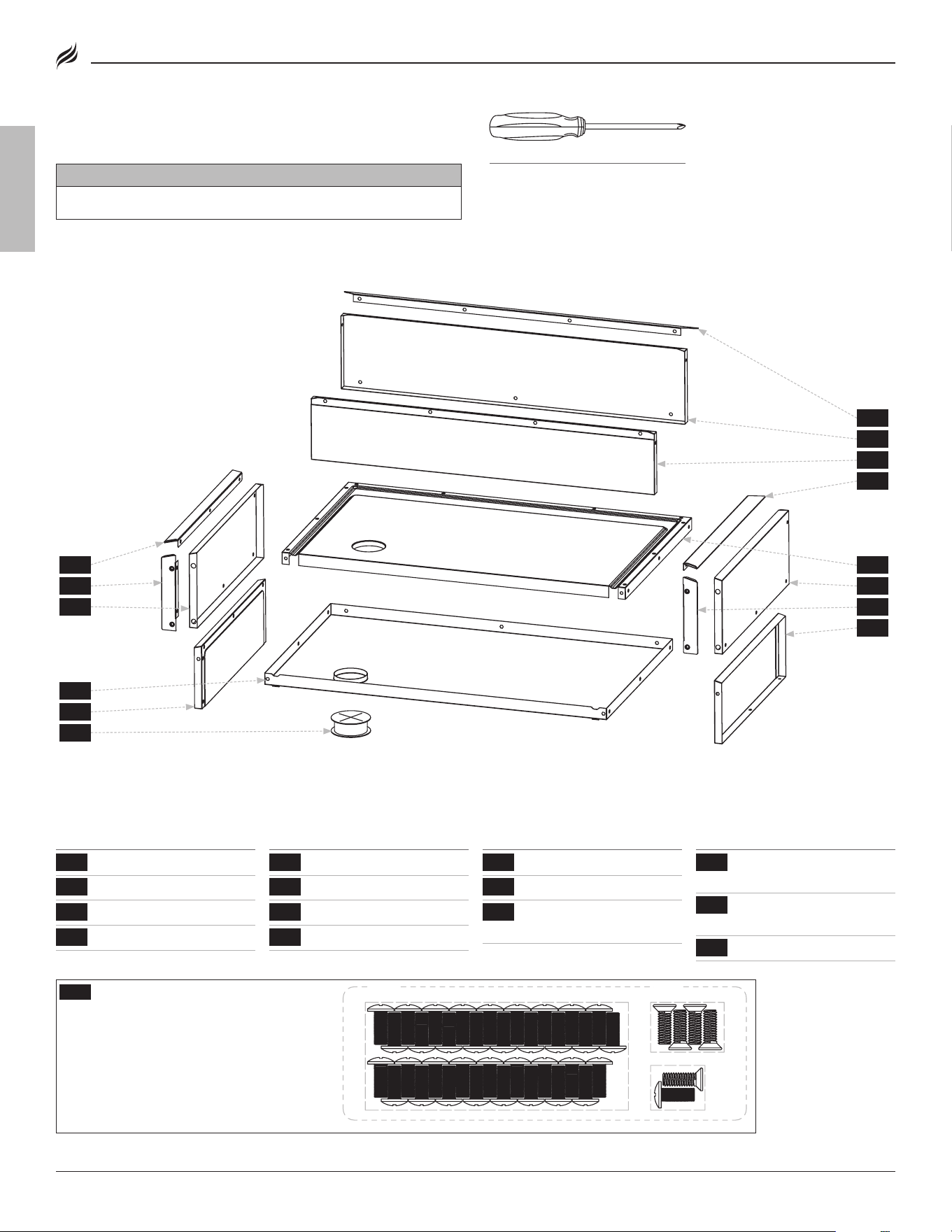
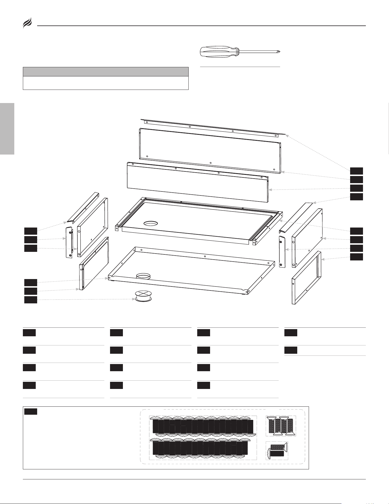
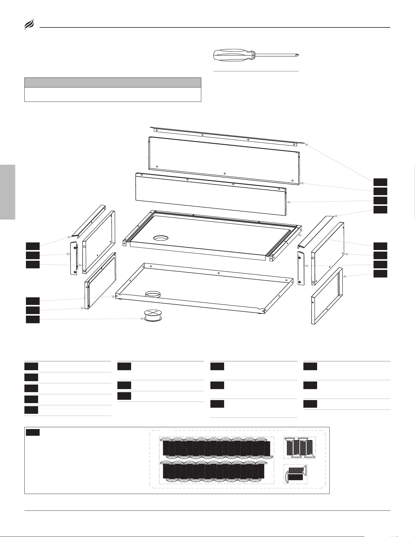
TOOL NEEDED:
#3 Phillips head screwdriver
{{15}} Hardware pack (1 piece)
a. M6x15 screws (35 pieces)
b. M6x15 countersunk screws (4 pieces)
c. Spares
PARTS LIST
PARTS
#
1
Outer base panel 1
2
Inner base panel
1
3
Rear inner panel
1
4
Rear outer panel
1
PARTS
#
5
Left inner panel 1
6
Left outer panel
1
7
Right inner panel
1
8
Right outer panel
1
PARTS
#
9
Rear decorative plate 1
10
Left decorative plate 1
1
11
Left decorative plate
2
1
PARTS
#
12
Right decorative
plate 1
1
13
Right decorative
plate 2
1
14
Silicone sleeve
1
EXPLODED VIEW
[a.] [b.]
[c.]
9
1
13
7
4
10
2
14
8
5
11
3
6 12
3BLACKSTONEPRODUCTS.COM/SUPPORT
6228 • 6430 | OWNER’S MANUAL
ENGLISH
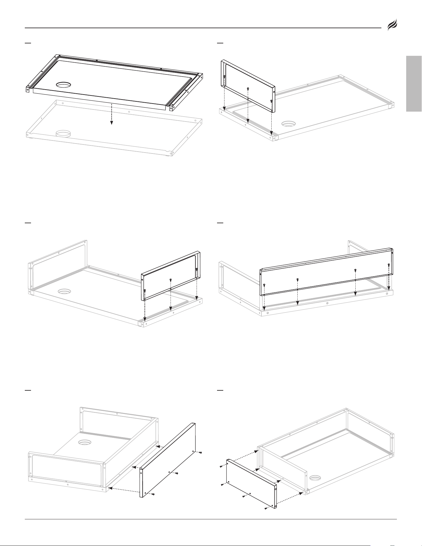
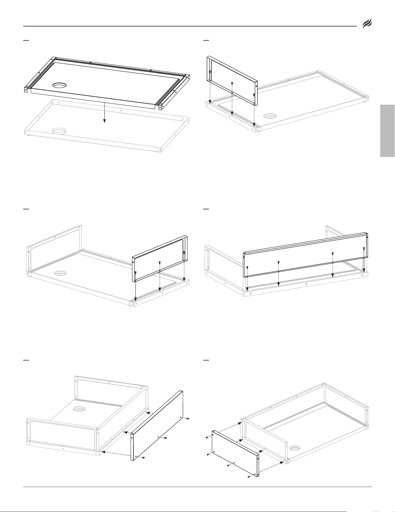
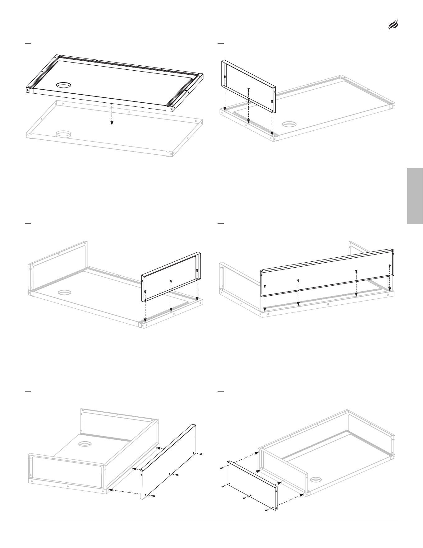
01
Place the inner base panel onto the outer base panel.
02
Use three (3) M6x15 screws [a.] to attach the left inner panel to the
base panel assembly.
03
Use three (3) M6x15 screws [a.] to attach the right inner panel to
the base panel assembly.
04
Use four (4) M6x15 screws [a.] to attach the rear inner panel to the
base panel assembly.
05
Use three (3) M6x15 screws [a.] to attach the rear outer panel to
the jacket base panel assembly.
06
Use four (4) M6x15 screws [a.] to attach the left outer panel to the
base panel assembly and rear panel assembly.
4 BLACKSTONEPRODUCTS.COM/SUPPORT
6228 • 6430 | OWNER’S MANUAL
ENGLISH
Please reference your Drop-In Griddle Owner’s Manual for installation
instructions.
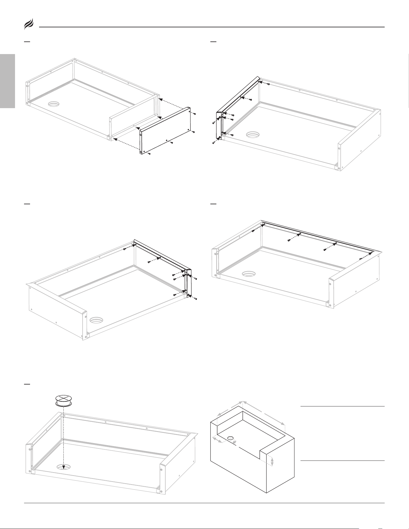
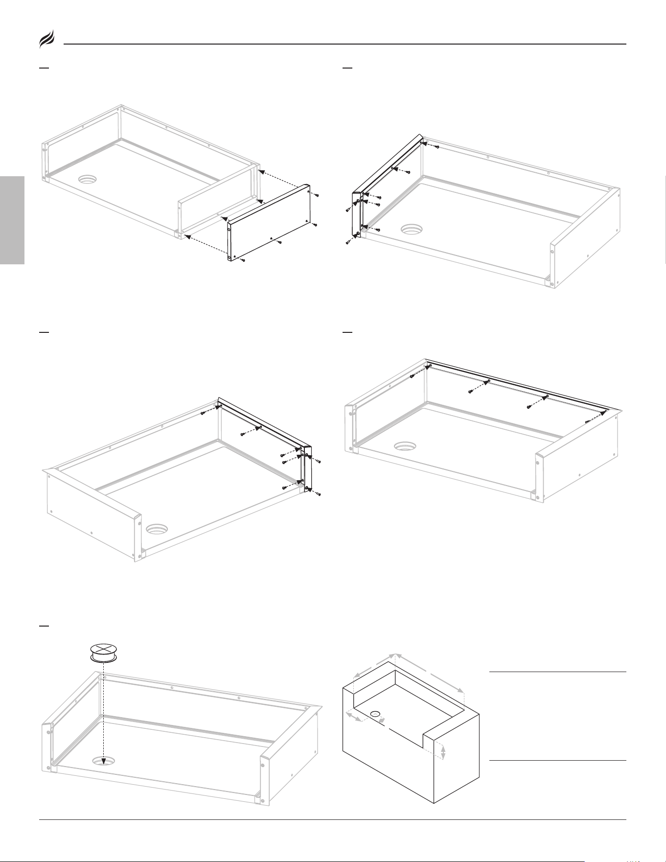
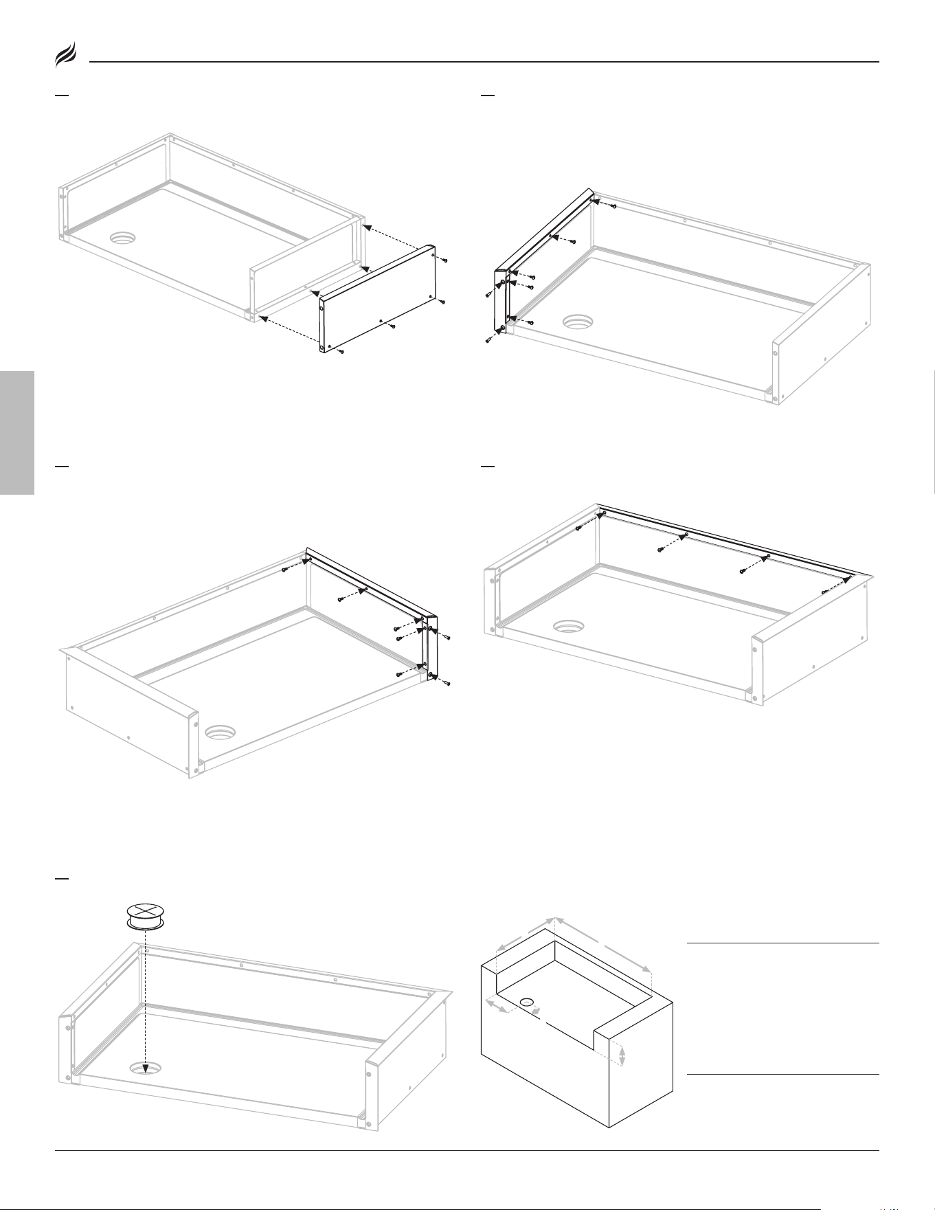
07
Use four (4) M6x15 screws [a.] to attach the right outer panel to
the base panel assembly and rear panel assembly.
08
Use five (5) M6x15 screws [a.] to attach the left decorative plate 2
(long one) to the left inner panel assembly.
Use two (2) M6x15 countersunk screws [b.] to attach the left decora-
tive plate 1 (short one) to the left inner panel assembly.
09
Use five (5) M6x15 screws [a.] to attach the right decorative plate
2 (long one) to the right inner panel assembly.
Use two (2) M6x15 countersunk screws [b.] to attach the right deco-
rative plate 1 (short one) to the right inner panel assembly.
10
Use four (4) M6x15 screws [a.] to attach the rear decorative plate
to the rear inner panel assembly.
11
Place the silicone sleeve in the base panel.
CAVITY MINIMUM DIMENSIONSCAVITY MINIMUM DIMENSIONS
A: A: 36" Width = 36" Width =
28" Width=28" Width=
43.35 in (110.11 cm) 43.35 in (110.11 cm)
35.4 in (89.92 cm)35.4 in (89.92 cm)
B: B: Depth = Depth = 26.09 in (66.27 cm)26.09 in (66.27 cm)
C: C: Height =Height = 9.16 in (23.27 cm)9.16 in (23.27 cm)
(> will interfere with hood) (> will interfere with hood)
HOLE MINIMUM DIMENSIONSHOLE MINIMUM DIMENSIONS
D: D: From side = From side = 9.39 in (23.86 cm)9.39 in (23.86 cm)
E: E: From front = From front = 5.05 in (12.83 cm)5.05 in (12.83 cm)
F: F: Diameter = Diameter = 4.33 in (10.93 cm)4.33 in (10.93 cm)
CC
EE
FF
DD
BB
aa
5BLACKSTONEPRODUCTS.COM/SUPPORT
6228 • 6430 | LE MANUEL DU PROPRIÉTAIRE
FRANÇAIS
CLÉ D’ALERTE DE SÉCURITÉ
⚠ attEntion
Indique une situation dangereuse qui, si elle n’est pas évitée, pour-
rait entraîner des blessures mineures ou modérées.
LE MANUEL DU PROPRIÉTAIRE
VESTE ISOLANTE
POUR LES PLAQUES CHAUFFANTES DROP-IN
6228 • 6430
v04
DISTRIBUÉ PAR NORTH ATLANTIC IMPORTS, LLC 1073 W 1700 N LOGAN, UT 84321 USA
BLACKSTONE EST UNE MARQUE DÉPOSÉE DE NORTH ATLANTIC IMPORTS, LLC
©2024 NORTH ATLANTIC IMPORTS. TOUS DROITS RÉSERVÉS.
CE PRODUIT PEUT ÊTRE COUVERT PAR UN OU PLUSIEURS BREVETS AMÉRICAINS ET/
OU INTERNATIONAUX ET PEUT INCLURE DES DEMANDES DE BREVET EN ATTENTE.
POUR PLUS D’INFORMATIONS, VEUILLEZ VISITER:
BLACKSTONEPRODUCTS.COM/PATENTS
BlackstoneProducts.com/support
CONTACTEZ LE SERVICE CLIENT AVANT DE RETOURNER L’APPAREIL AU DÉTAILLANT.
6 BLACKSTONEPRODUCTS.COM/SUPPORT
6228 • 6430 | LE MANUEL DU PROPRIÉTAIRE
FRANÇAIS
inStRuCtionS DE MontaGE
Trouvez un grand espace propre pour assembler votre appareil.
Retirez tout le matériel d’emballage avant l’assemblage.
⚠ attEntion
Bouts pointus. Portez des gants lors de l’assemblage.
OUTIL NÉCESSAIRE:
Tournevis cruciforme n°3
{{15}} Pack de matériel (1 pièce)
a. Vis M6x15 (35 pièces)
b. Vis à tête fraisée M6x15 (4 pièces)
c. Pièces de rechange
LISTE DES PIECES
PIÈCES
#
1
Panneau de base
extérieur
1
2
Panneau de base
intérieur
1
3
Panneau intérieur
arrière
1
4
Panneau extérieur
arrière
1
PIÈCES
#
5
Panneau intérieur
gauche
1
6
Panneau extérieur
gauche
1
7
Panneau intérieur
droit
1
8
Panneau extérieur
droit
1
PIÈCES
#
9
Plaque décorative
arrière
1
10
Plaque décorative
gauche 1
1
11
Plaque décorative
gauche 2
1
12
Plaque décorative
droite 1
1
PIÈCES
#
13
Plaque décorative
droite 2
1
14
Manchon en silicone
1
VUE ÉCLATÉE
[a.] [b.]
[c.]
9
1
13
7
4
10
2
14
8
5
11
3
6 12
7BLACKSTONEPRODUCTS.COM/SUPPORT
6228 • 6430 | LE MANUEL DU PROPRIÉTAIRE
FRANÇAIS
01
Placez le panneau de base intérieur sur le panneau de base
extérieur.
02
Utilisez trois (3) vis M6x15 [a.] pour fixer le panneau intérieur
gauche à l’assemblage du panneau de base.
03
Utilisez trois (3) vis M6x15 [a.] pour fixer le panneau intérieur droit
à l’assemblage du panneau de base.
04
Utilisez quatre (4) vis M6x15 [a.] pour fixer le panneau intérieur
arrière à l’ensemble du panneau de base.
05
Utilisez trois (3) vis M6x15 [a.] pour fixer le panneau extérieur
arrière à l’ensemble du panneau de base de la veste.
06
Utilisez quatre (4) vis M6x15 [a.] pour fixer le panneau extérieur
gauche à l’ensemble du panneau de base et à l’ensemble du
panneau arrière.
8 BLACKSTONEPRODUCTS.COM/SUPPORT
6228 • 6430 | LE MANUEL DU PROPRIÉTAIRE
FRANÇAIS
Veuillez consulter le manuel du propriétaire de votre plaque chauf-
fante encastrable pour les instructions d’installation.
07
Utilisez quatre (4) vis M6x15 [a.] pour fixer le panneau extérieur
droit à l’ensemble du panneau de base et à l’ensemble du
panneau arrière.
08
Utilisez cinq (5) vis M6x15 [a.] pour fixer la plaque décorative
gauche 2 (la longue) à l’assemblage du panneau intérieur gauche.
Utilisez deux (2) vis à tête fraisée M6x15 [b.] pour fixer la plaque
décorative gauche 1 (la plus courte) à l’assemblage du panneau
intérieur gauche.
09
Utilisez cinq (5) vis M6x15 [a.] pour fixer la plaque décorative
droite 2 (la longue) à l’assemblage du panneau intérieur droit.
Utilisez deux (2) vis à tête fraisée M6x15 [b.] pour fixer la plaque
décorative droite 1 (la courte) à l’assemblage du panneau
intérieur droit.
10
Utilisez quatre (4) vis M6x15 [a.] pour fixer la plaque décorative
arrière à l’ensemble du panneau intérieur arrière.
11
Placez le manchon en silicone dans le panneau de base.
DIMENSIONS MINIMALES DE LA DIMENSIONS MINIMALES DE LA
CAVITÉCAVITÉ
A: A: 36" Largeur = 36" Largeur =
28" Largeur=28" Largeur=
43.35 in (110.11 cm) 43.35 in (110.11 cm)
35.4 in (89.92 cm)35.4 in (89.92 cm)
B: B: Profondeur = Profondeur = 26.09 in (66.27 cm)26.09 in (66.27 cm)
C: C: Hauteur =Hauteur = 9.16 in (23.27 cm)9.16 in (23.27 cm)
(> interférera avec la capuche) (> interférera avec la capuche)
DIMENSIONS MINIMALES DU TROUDIMENSIONS MINIMALES DU TROU
D: D: Du côté =Du côté = 9.39 in (23.86 cm)9.39 in (23.86 cm)
E: E: De face =De face = 5.05 in (12.83 cm)5.05 in (12.83 cm)
F: F: Diamètre =Diamètre = 4.33 in (10.93 cm)4.33 in (10.93 cm)
CC
EE
FF
DD
BB
aa
9BLACKSTONEPRODUCTS.COM/SUPPORT
6228 • 6430 | EL MANUAL DEL PROPIETARIO
ESPAÑOL
TECLA DE ALERTA DE SEGURIDAD
⚠ PRECauCiÓn
Indica una situación peligrosa que, si no se evita, podría provocar
lesiones leves o moderadas.
EL MANUAL DEL PROPIETARIO
CHAQUETA AISLANTE
PARA PLANCHAS EMPOTRABLES
6228 • 6430
v04
DISTRIBUIDO POR NORTH ATLANTIC IMPORTS, LLC 1073 W 1700 N LOGAN, UT 84321 EE.
UU. BLACKSTONE ES UNA MARCA REGISTRADA DE NORTH ATLANTIC IMPORTS, LLC
©2024 NORTH ATLANTIC IMPORTS. RESERVADOS TODOS LOS DERECHOS.
ESTE PRODUCTO PUEDE ESTAR CUBIERTO POR UNA O MÁS PATENTES
ESTADOUNIDENSES Y/O INTERNACIONALES EMITIDAS Y PUEDE INCLUIR SOLICITUDES
DE PATENTE PENDIENTES.
PARA OBTENER MÁS INFORMACIÓN, VISITE: BLACKSTONEPRODUCTS.COM/PATENTS
BlackstoneProducts.com/support
COMUNÍQUESE CON ATENCIÓN AL CLIENTE ANTES DE DEVOLVER EL
ELECTRODOMÉSTICO AL MINORISTA.
10 BLACKSTONEPRODUCTS.COM/SUPPORT
6228 • 6430 | EL MANUAL DEL PROPIETARIO
ESPAÑOL
inStRuCCionES DE MontaJE
Encuentre un área grande y limpia para ensamblar su elec-
trodoméstico.
Retire todo el material de embalaje antes del montaje.
⚠ PRECauCiÓn
Bordes afilados. Utilice guantes durante el montaje.
HERRAMIENTA NECESARIA:
Destornillador Phillips n.º 3
{{15}} Paquete de hardware (1 pieza)
a. Tornillos M6x15 (35 piezas)
b. Tornillos avellanados M6x15 (4 piezas)
c. Repuestos
LISTA DE PARTES
PARTES
#
1
Panel de base exterior
1
2
Panel de base interior
1
3
Panel interior trasero
1
4
Panel exterior trasero 1
5
Panel interior izquierdo 1
PARTES
#
6
Panel exterior izqui-
erdo
1
7
Panel interior derecho 1
8
Panel exterior derecho 1
PARTES
#
9
Placa decorativa
trasera
1
10
Placa decorativa
izquierda 1
1
11
Placa decorativa
izquierda 2
1
PARTES
#
12
Placa decorativa
derecha 1
1
13
Placa decorativa
derecha 2
1
14
Funda de silicona
1
VISTA EN DESPIECE ORDENADO
[a.] [b.]
[c.]
9
1
13
7
4
10
2
14
8
5
11
3
6 12
11BLACKSTONEPRODUCTS.COM/SUPPORT
6228 • 6430 | EL MANUAL DEL PROPIETARIO
ESPAÑOL
01
Coloque el panel de base interior sobre el panel de base exterior.
02
Utilice tres (3) tornillos M6x15 [a.] para fijar el panel interior izqui-
erdo al conjunto del panel base.
03
Utilice tres (3) tornillos M6x15 [a.] para fijar el panel interior
derecho al conjunto del panel base.
04
Utilice cuatro (4) tornillos M6x15 [a.] para fijar el panel interior
trasero al conjunto del panel base.
05
Utilice tres (3) tornillos M6x15 [a.] para fijar el panel exterior
trasero al conjunto del panel base de la cubierta.
06
Utilice cuatro (4) tornillos M6x15 [a.] para fijar el panel exterior
izquierdo al conjunto del panel base y al conjunto del panel trasero.
12 BLACKSTONEPRODUCTS.COM/SUPPORT
6228 • 6430 | EL MANUAL DEL PROPIETARIO
ESPAÑOL
Consulte el manual del propietario de su plancha empotrable para
obtener instrucciones de instalación.
07
Utilice cuatro (4) tornillos M6x15 [a.] para fijar el panel exterior
derecho al conjunto del panel base y al conjunto del panel trasero.
08
Utilice cinco (5) tornillos M6x15 [a.] para fijar la placa decorativa
izquierda 2 (la larga) al conjunto del panel interior izquierdo.
Utilice dos (2) tornillos avellanados M6x15 [b.] para fijar la placa
decorativa izquierda 1 (la corta) al conjunto del panel interior
izquierdo.
09
Utilice cinco (5) tornillos M6x15 [a.] para fijar la placa decorativa
derecha 2 (la larga) al conjunto del panel interior derecho.
Utilice dos (2) tornillos avellanados M6x15 [b.] para fijar la placa
decorativa derecha 1 (la corta) al conjunto del panel interior derecho.
10
Utilice cuatro (4) tornillos M6x15 [a.] para fijar la placa decorativa
trasera al conjunto del panel interior trasero.
11
Coloque la funda de silicona en el panel base.
DIMENSIONES MÍNIMAS DE LA DIMENSIONES MÍNIMAS DE LA
CAVIDADCAVIDAD
A: A: 36" ancho = 36" ancho =
28" ancho =28" ancho =
43.35 in (110.11 cm) 43.35 in (110.11 cm)
35.4 in (89.92 cm)35.4 in (89.92 cm)
B: B: Profundidad = Profundidad = 26.09 in (66.27 cm)26.09 in (66.27 cm)
C: C: altura =altura = 9.16 in (23.27 cm)9.16 in (23.27 cm)
(> interferirá con el capó) (> interferirá con el capó)
DIMENSIONES MÍNIMAS DEL DIMENSIONES MÍNIMAS DEL
AGUJEROAGUJERO
D: D: De lado = De lado = 9.39 in (23.86 cm)9.39 in (23.86 cm)
E: E: De frente =De frente = 5.05 in (12.83 cm)5.05 in (12.83 cm)
F: F: Diámetro =Diámetro = 4.33 in (10.93 cm)4.33 in (10.93 cm)
CC
EE
FF
DD
BB
aa