

Qogrisys O9101SA DATA SHEET
www.qogrisys.com 1 OFEIXIN TECHNOLOGY LIMITED
Cover of Approval Sheet
PRODUCT NAME
Part No.
Description
O9101SA
FWAAO9101SA10
WQ9101S SDIO 3.3V 1T1R 12*12*1.9mm 80MHz 11ax WI
FI6+BT5.4 External 1Antenna
Customer:
Customer P/N:
Signature:
Date:
Maker Information:
SHENZHEN OFEIXIN TECHNOLOGY LIMITED
902, Building 4, Guangming Fenghuang Plaza, Dongkeng Community,
Fenghuang Street, Guangming District, Shenzhen, China

Qogrisys O9101SA DATA SHEET
www.qogrisys.com 2 OFEIXIN TECHNOLOGY LIMITED
Revision History
Version
Date
Description
Draft
Approved
V1.0
2025-09-16
Preliminary Project version
EZX
Ben·Chen
V2.0
2025-11-11
Revise Company Logo and Address
Revised Operating Temperature
Specifications
EZX
Ben·Chen
V2.1
2025-12-15
Adjust layout dimensions
EZX
Ben·Chen
V2.2
2026-01-29
Correct the pin description error
EZX
Ben·Chen

Qogrisys O9101SA DATA SHEET
www.qogrisys.com 3 OFEIXIN TECHNOLOGY LIMITED
CONTENTS
1.OVERVIEW ...................................................................................................................................... 4
1.1 INTRODUCTION ............................................................................................................................... 4
1.2 FEATURES ...................................................................................................................................... 4
1.3 GENERAL SPECIFICATION .............................................................................................................. 5
1.4 RECOMMENDED OPERATING RATING ............................................................................................ 5
2. RF SPECIFICATION .......................................................................................................................... 5
2.1 WI-FI RF SPECIFICATION .............................................................................................................. 5
2.2 BT RF SPECIFICATION .................................................................................................................. 6
3.PIN ASSIGNMENTS .......................................................................................................................... 7
3.1 PIN OUTLINE .................................................................................................................................. 7
3.2 PIN DEFINITION .............................................................................................................................. 7
4.DIMENSIONS ................................................................................................................................... 9
4.1 PHYSICAL DIMENSIONS AND MODULE PHOTO .............................................................................. 9
4.2 MODULE PHYSICAL DIMENSIONS................................................................................................... 9
5 REFERENCE DESIGN ....................................................................................................................... 10
5.1 EXTERNAL ANTENNA .................................................................................................................... 10
6 RECOMMENDED REFLOW PROFILE ................................................................................................ 10
7 PACKAGE ....................................................................................................................................... 11
7.1 REEL ............................................................................................................................................. 11
7.2 STORAGE TEMPERATURE AND HUMIDITY ................................................................................... 11

Qogrisys O9101SA DATA SHEET
www.qogrisys.com 4 OFEIXIN TECHNOLOGY LIMITED
1.Overview
1.1 Introduction
The O9101SA is a dual-mode module, support 1x1 2.4G + 5G dual-frequency Wi-Fi function
and Bluetooth function. Wi-Fi Da We supports Wi-Fi protocol IEEE 802.11ax and backward
compatibility protocol 802.11a/b/g/n/ac. The Bluetooth subsystem supports the Bluetooth
system Protocol 5.4 with low-power audio.
The O9101SA module integrates five high-performance RISC-VCPUs, high-speed interfaces
(SDIO3.0).The module supports a good radio frequency with very low power consumption
And baseband performance.
1.2 Features
⚫ Supported for the IEEE 802.11 a / b / g / n / ac / ax protocol.
⚫ Dual-band 2.4 GHz/5 GHz support.
⚫ 20MHz/40MHz channel bandwidth for 2.4 GHz and 20MHz/40MHz/80MHz channel
bandwidth for 5 GHz.
⚫ Support WFA、WPA/WPA2/WPA3、WEP、WAPI.
⚫ Supports IEEE 802.11k /v/r protocol.
⚫ Support Soft AP/STA/P2P mode.
⚫ Fully compatible with Bluetooth 5.4 protocol.
⚫ Support for BT / BLE dual-mode.

Qogrisys O9101SA DATA SHEET
www.qogrisys.com 5 OFEIXIN TECHNOLOGY LIMITED
1.3 General Specification
Model Name
O9101SA
Product Description
Support WiFi6+BT5.4
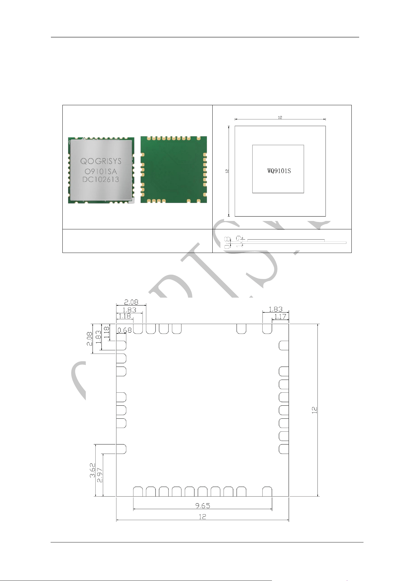
Dimension
L x W x H: 12 x 12 x 1.9 (typical) mm
Wi-Fi Interface
SDIO3.0
BT Interface
UART/PCM
Operting temperature
-10 to 70℃
Storage temperature
-40℃ to 120℃
Note: This module operates normally within a temperature range of -10℃ to 70℃; continuous
operation at extreme temperature points over extended periods is not recommended.
1.4 Recommended Operating Rating
Feature
Minimum
Type
Maximum
Units
Operating Temperature
-10
25
70
°C
VCC
3.15
3.3
3.45
V
Power
Consumption (Type
VCC)
TX (2.4G HE40)
298 mA
RX (2.4G HE40)
179 mA
TX (5G HE80)
317 mA
RX (5G HE80)
208 mA
BT TX(3DH5)
171 mA
BT RX(3DH5)
98 mA
2. RF Specification
2.1 Wi-Fi RF Specification
2.4GHz RF Specification
Feature
Description
Operating Frequency
US: 2412~2462MHz
EU: 2412-2472MHz
Standards
Wi-Fi: IEEE 802.11b/g/n/ax & Wi-Fi compliant
Operating Channel
US: 11; EU: 13
Modulation
DSSS, OFDM, OFDMA
PHY Data rates
Wi-Fi:802.11b:11,5.5,2,1Mbps
802.11g:54,48,36,24,18,12,9,6Mbps
802.11n: up to 150Mbps (2.4G HT40)
802.11ax: up to 286Mbps data rate (2.4G HE40)
RF Output Power: 14.0dBm(Only for CE)
5GHz RF Specification
Feature
Description
Operating Frequency
5150-5250MHz; 5725-5850MHz
Standards
Wi-Fi: IEEE 802.11 a/n/ac/ax Wi-Fi compliant

Qogrisys O9101SA DATA SHEET
www.qogrisys.com 6 OFEIXIN TECHNOLOGY LIMITED
Modulation
OFDM, OFDMA
PHY Data rates
Wi-Fi: 802.11a:54,48,36,24,18,12,9,6Mbps
802.11n: up to 150Mbps(5G HT40)
802.11ac: up to 433Mbps (5G VHT80)
802.11ax: up to 600Mbps data rate (5G HE80)
RF Output Power: Band 1: 15.0 dBm, Band 4: 13.98 dBm(Only for CE)
2.2 BT RF Specification
Feature
Description
Operating Frequency
2.402~2.480GHz
Number of Channels
BDR/EDR: 79 channels
BLE: 40 channels
Standards
Bluetooth V5.4
Modulation
8DPSK, π/4 DQPSK, GFSK
PHY Data rates
Supports 2Mbps Bluetooth Low Energy(BLE),BLELong Range
Output Power
2.0 dBm(Only for CE)
Qogrisys O9101SA DATA SHEET
www.qogrisys.com 7 OFEIXIN TECHNOLOGY LIMITED
3.Pin Assignments
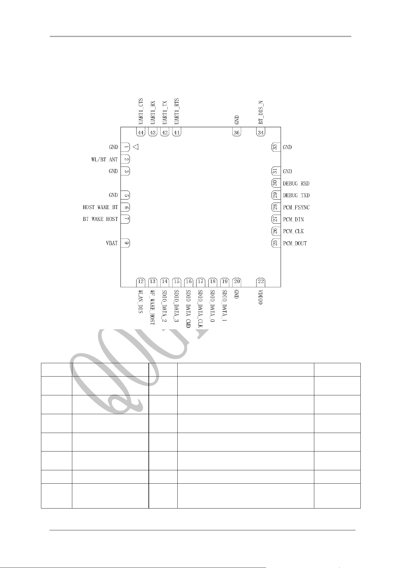
3.1 Pin Outline
3.2 Pin Definition
PIN
Name
Type
Description
Voltage
1
GND
-
Ground connections
2
WL/BT_ANT
I/O
WLAN and BT RF I/O port
3
GND
-
Ground connections
5
GND
-
Ground connections
6
HOST_WAKE_BT
I
GPIOB3/HOST_WAKE_BT
7
BT_WAKE_HOST
O
GPIOB3/HOST_WAKE_BT
9
VBAT
I/PU
Main power voltage source input
3.3V

Qogrisys O9101SA DATA SHEET
www.qogrisys.com 8 OFEIXIN TECHNOLOGY LIMITED
12
WLAN_DIS
P
Enable pin for WLAN Radio ON: pull
high; OFF: pull low External pull low to
disable WLAN Radio
VDDIO
13
WF Wake Up Host
WF Wake Up Host
VDDIO
14
SD_D2
SDIO data line 2
VDDIO
15
SD_D3
SDIO data line 3
VDDIO
16
SD_CMD
SDIO command line
VDDIO
17
SD_CLK
SDIO clock line
VDDIO
18
SD_D0
SDIO data line 0
VDDIO
19
SD_D1
SDIO data line 1
VDDIO
20
GND
-
Ground connections
22
VDDIO
I/O Voltage
1.8 or 3.3V
25
PCM_DOUT
PCM Data output
VDDIO
26
PCM_CLK
PCM clock
VDDIO
27
PCM_DIN
PCM data input
VDDIO
28
PCM_SYNC
PCM sync signal
VDDIO
29
DEBUG_TXD
Debug UART TXD don't connect to
ground
VDDIO
30
DEBUG_RXD
Debug UART RXD don't connect to
ground
VDDIO
31
GND
-
Ground connections
33
GND
-
Ground connections
34
BT_DIS_N
I/PU
Enable pin for Bluetooth device ON: pull
high; OFF: pull low External pull low to shut
down BT,recommended 10K pull high.
VDDIO
36
GND
-
Ground connections
41
UART1_RTS
BT_UART1_RTS
VDDIO
42
UART1_TX
BT_UART1_TX
VDDIO
43
UART1_RX
BT_UART1_RX
VDDIO
44
UART1_CTS
BT_UART1_CTS
VDDIO
Qogrisys O9101SA DATA SHEET
www.qogrisys.com 10 OFEIXIN TECHNOLOGY LIMITED
5 Reference Design
5.1 External Antenna
When the customer selects an external antenna, the external antenna selected must meet the
parameter requirements specified ,Impedance 50Ω
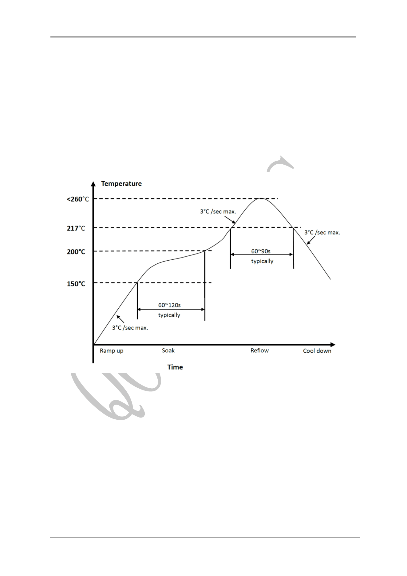
6 Recommended Reflow Profile
Referred to IPC/JEDEC standard.
Peak Temperature : <260°C
Number of Times : 2 times max
Qogrisys O9101SA DATA SHEET
www.qogrisys.com 11 OFEIXIN TECHNOLOGY LIMITED
7 Package
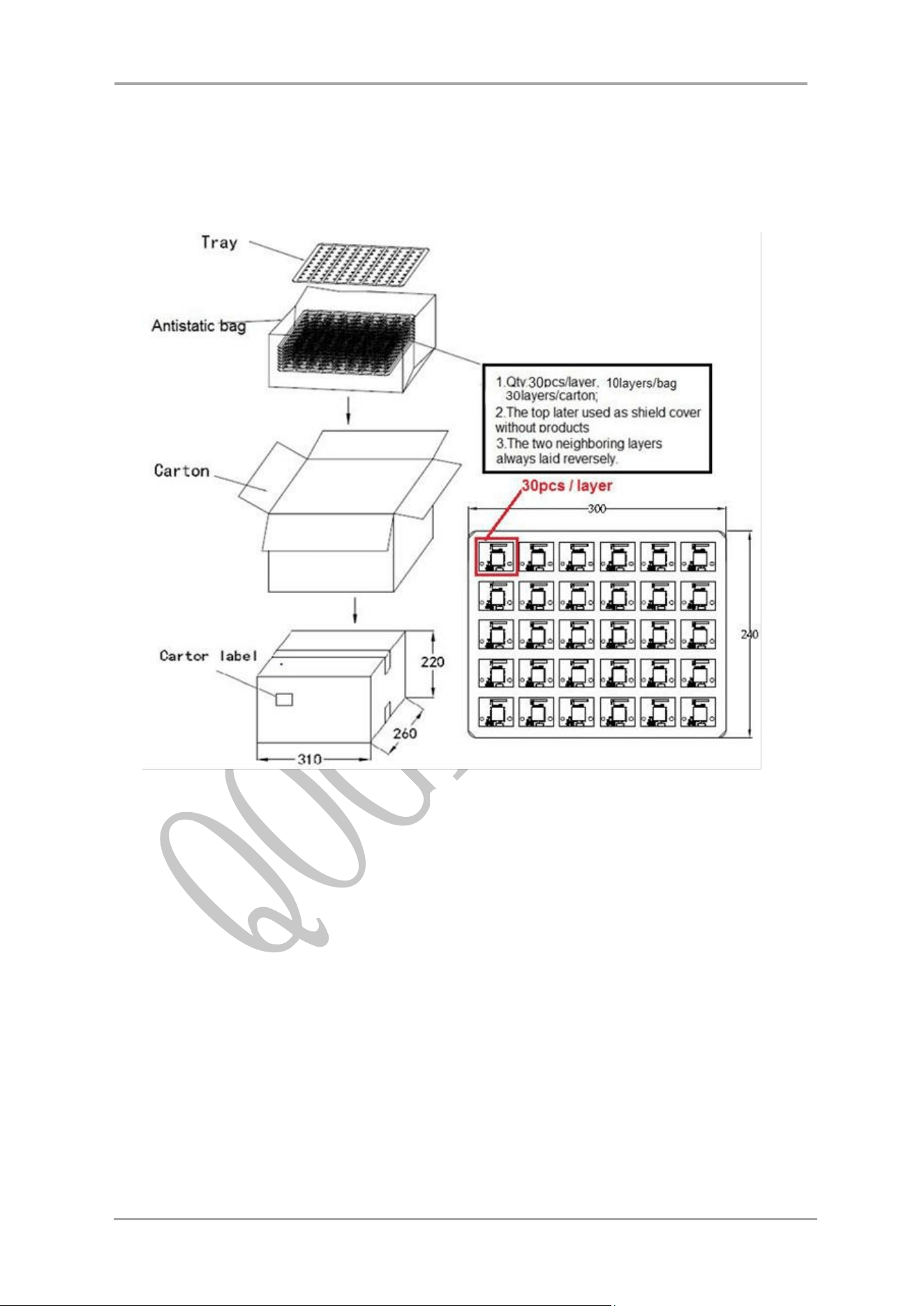
7.1 Reel
7.2 Storage Temperature And Humidity
The Modules is a Moisture Sensitive Device level 3, in according with standard IPC/JEDEC
J-STD-020, tak e care all the relatives requirements for using this kind of components.
Moreover, the customer has to take care of the following conditions:
a) Calculated shelf life in sealed bag: 12 months at <40°C and <90% relative humidity
(RH).
b) Environmental condition during the production: 30°C / 60% RH according to
IPC/JEDEC J-STD-033A paragraph 5.
c) The maximum time between the opening of the sealed bag and the reflow process
must be 168 hours if condition.
d) “IPC/JEDEC J-STD-033A paragraph 5.2” is respected.
e) Baking is required if conditions b) or c) are not respected.
f) Baking is required if the humidity indicator inside the bag indicates 10% RH or more.

Qogrisys O9101SA DATA SHEET
www.qogrisys.com 12 OFEIXIN TECHNOLOGY LIMITED
FCC Caution:
Any Changes or modifications not expressly approved by the party responsible for
compliance could void the user's authority to operate the equipment.
This device complies with part 15 of the FCC Rules. Operation is subject to the following
two conditions: (1) This device may not cause harmful interference, and (2) this device
must accept any interference received, including interference that may cause undesired
operation.
This transmitter must not be co-located or operating in conjunction with any other antenna
or transmitter.
IMPORTANT NOTE:
Note: This equipment has been tested and found to comply with the limits for a Class B digital
device, pursuant to part 15 of the FCC Rules. These limits are designed to provide
reasonable protection against harmful interference in a residential installation. This equipment
generates, uses and can radiate radio frequency energy and, if not installed and used in
accordance with the instructions, may cause harmful interference to radio communications.
However, there is no guarantee that interference will not occur in a particular installation. If
this equipment does cause harmful interference to radio or television reception, which can be
determined by turning the equipment off and on, the user is encouraged to try to correct the
interference by one or more of the following measures:
—Reorient or relocate the receiving antenna.
—Increase the separation between the equipment and receiver.
—Connect the equipment into an outlet on a circuit different from that to which the receiver is
connected.
—Consult the dealer or an experienced radio/TV technician for help.
FCC Radiation Exposure Statement:
This equipment complies with FCC radiation exposure limits set forth for an
uncontrolled environment .This equipment should be installed and operated with
minimum distance 20cm between the radiator& your body.
Integration instructions for host product manufacturers according to KDB
996369 D03 OEM Manual v01r01
2.2 List of applicable FCC rules
CFR 47 FCC PART 15 SUBPART A&C&E has been investigated. It is applicable to
the modular.
2.3 Specific operational use conditions
This module is stand-alone modular. If the end product will involve the Multiple
simultaneously transmitting condition or different operational conditions for a stand-

Qogrisys O9101SA DATA SHEET
www.qogrisys.com 13 OFEIXIN TECHNOLOGY LIMITED
alone modular transmitter in a host, host manufacturer have to consult with module
manufacturer for the installation method in end system.
2.4 Limited module procedures
Not applicable
2.5 Trace antenna designs
Not applicable
2.6 RF exposure considerations
To maintain compliance with FCC’s RF Exposure guidelines, This equipment should
be installed and operated with minimum distance of 20cm from your body.
2.7 Antennas
This radio transmitter FCC ID: 2AT5W-O9101SA has been approved by Federal
Communications Commission to operate with the antenna types listed below, with the
maximum permissible gain indicated. Antenna types not included in this list that have
a gain greater than the maximum gain indicated for any type listed are strictly
prohibited for use with this device.
Antenna
Description
Antenna Type
Frequency Range (MHz)
Impedance
(Ω)
Maximum antenna
gain(dBi)
Bluetooth/Wi-Fi
Antenna
FPC
2400-2500MHz
5150-5850MHz
50
BT&2.4G Wi-Fi: 1.76dBi
5G Wi-Fi: 1.47dBi(B1);
1.64dBi(B4)
2.8 Label and compliance information
The final end product must be labeled in a visible area with the following" Contains
FCC ID: 2AT5W-O9101SA”
2.9 Information on test modes and additional testing requirements
Host manufacturer is strongly recommended to confirm compliance with FCC
requirements for the transmitter when the module is installed in the host.
2.10 Additional testing, Part 15 Subpart B disclaimer
Host manufacturer is responsible for compliance of the host system with module
installed with all other applicable requirements for the system such as Part 15 B

Qogrisys O9101SA DATA SHEET
www.qogrisys.com 14 OFEIXIN TECHNOLOGY LIMITED
Conformity Assessment of the Radio Module to the RED
This radio module is for professional installation only. When installing this radio module
permanently into a host product to a create new radio equipment device; the manufacturer
responsible for placing the final radio product on the market in the EU must assess if the
combination of this radio module and the host product complies with the essential
requirements of the RE Directive 2014/53/EU.
Firmware version: 2.2.3.80
Test Antenna: FPC antenna and maximum gain 2.4G: 1.76dBi, 5G: 1.64dBi
The final radio product will need to be fully assessed to Article 3.1a of the RED, for product
safety With regard to RF exposure for Article 3.1a of the RED, the manufacturer of the final
radio product will need to assess if the compliance assessment of the original radio
equipment/module remains relevant to the final radio product, or if further action is necessary.
This equipment should be installed and operated with minimum distance 20cm between the
radiator& your body.
If the final radio equipment is used at the same distance from a person or domesticated
animal as the radio module was assessed, (for example: >20cm), then the final radio product
assessment could conclude that the final radio product is compliant with the RF exposure
requirements without additional actions.
If the final radio equipment is used at a closer distance from a person or domesticated animal
than the radio module was assessed, then the final radio product assessment could not
automatically conclude that the final radio product is compliant with the RF exposure
requirements without additional actions; and further assessment is necessary.
The final radio product will need to be fully assessed to Article 3.1b of the RED, for EMC.
EMC testing of the radio module will have been performed on some sort of temporary host or
test jig; but now the module is in a new host product and the EMC performance of the final
radio product must be assessed. Most likely the host product will have its own EMC
assessment for other functions, which should be performed with the radio module installed;
and inclusion of the radio module into the host product will also require an assessment, such
as to the relevant applicable part of EN 301 489, on the final radio product.
In theory, radio transmitter or receiver measurements made as conducted measurements at a
radio module antenna port may be considered applicable to the radio performance of the final
radio product. However, in this example, the radio module does not have an antenna port.
The radio module has a pin which leads through a PCB trace to an antenna on the host
product. If the manufacturer of the final radio product wishes to use conducted power,
conducted emissions or receiver performance measurements from the radio module to show
compliance of the final radio product, then they will need to exactly follow the detailed
instructions from the radio module manufacturer; including input voltage, driver software,
environmental conditions, antenna trace layout design construction and material, circuit board
layout design construction and material, nearby circuitry, etc. In reality, it is expected that
manufacturers of final radio products will need to test the output power, conducted spurious
emissions and receiver performance requirements on the final radio product; and not take the
results of those test cases from the radio module test reports. Radiated test cases will also
need to be performed on the final radio product.