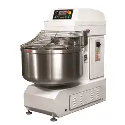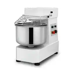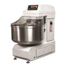
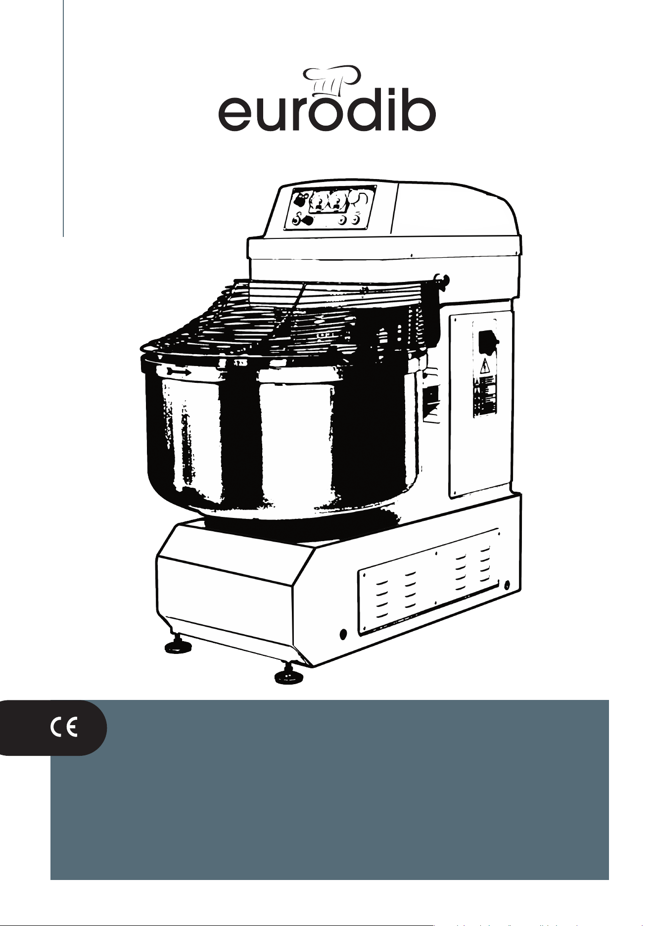
Spiral mixer xed bowl
MSP
50-60-80-100-130-160-200-250-300
user and maintenance manual

MADE IN ITALY
3
EN
spiral mixer xed bowl
4
1 INTRODUCTION
1.1 FOREWORD
This instruction manual is for operators and staff appointed and authorised to use the machine. It is
also intended for the employer, the managers and supervisors of the user company, who must read it and
thoroughly understand it, to allow them, as the case may be, to implement part of the obligations that legislation
and standards in force attribute to them for health and safety in the workplace; these obligations also include
ensuring operators are adequately trained and informed, including in practice (being simple and understandable
based on the insight one would reasonably expect the relevant parties to have), on correct and safe use of the
machine and on risks characterising the workplace and/or the role.
The manual is composed of multiple sections, which can be summarised as follows:
Instructions on movement, transport and installation; they are mostly contained in the first part of Chapter 3
and are for those responsible for moving, transporting, installing and carrying out first start-up of the machine
with the purpose of providing important know-how (except know-how already acquired by an expert technician
and/or professionally trained and/or specialist technician) to carry out these operations in a correct manner and
in the safest way possible.
Instructions on use and routine maintenance in safe conditions; they are mostly contained in Chapter 2
and in part of Chapters 3, 4 and 5; they are for the employer, managers, supervisors and the operators of the
user company. They include instructions for current use and for maintenance, cleaning and control operations of
the machine which, due to their simplicity and little danger, do not require particular experience or professional
skills and can also be carried out by the operator using the machine for production purposes.
Instructions on extraordinary maintenance; they are mostly contained in the remaining part of Chapters 4
and 5; they are for the employer, managers, supervisors and operators of the user company and specialist staff
appointed to carry out routine and/or extraordinary maintenance on the machine. They include important
instructions for safety purposes which must be followed in maintenance, adjustment and control operations
which, due to their complexity and/or danger, must be carried out by specialist, expert and professionally
qualified staff in possession of the technical-legislative know-how to carry out state-of-the-art works in safe
conditions. Given the experience the staff appointed for these types of interventions must have, the instructions
of a technical nature are omitted which are not decisive in carrying out the works in safe conditions and/or of
which, considering the professional profile, said staff must already be aware.
Instructions on decommissioning and/or dismantling are mostly
contained in Chapter 6.
The references made to specific chapters or paragraphs must be intended as also made to all relevant sub-
paragraphs, where, for example, par. is given 2.3, the reference must be intended as encompassing all the
paragraphs from 2.3.1 to 2.3.4.
Before carrying out any operation (installation, adjustment, use, repair, etc.), read this manual carefully and
clearly understand all the purposes and meanings for good operation of the machine, its correct maintenance,
adequate know-how of its safety devices and any residual risks its use may involve.
Keep the manual and the documents attached in a safe place, known to use and/or maintenance operators.
Keep it dry and away from atmospheric agents which over time could get damaged (e.g. in a clear, plastic
envelope); leave a copy of it near the machine for quick consultation by the operators.
If lost or worn, immediately request a copy to EURODIB specifying the identification data of the
machine (serial number, year of manufacture, model, invoice number, etc.).
This manual reflects the technical status of the machine at time of release on the market and cannot be
considered inadequate solely due to subsequent updates based on new experience and/or new technical
solutions.
The manufacturer cannot be considered in any way liable for the suitability of the use location of the machine
and the support services to it, providing some important instructions in this manual in this respect.
EURODIB. reserves the right to update the machines and manuals without this implying an obligation on its
parts to update the machines and/or manuals from previous production.
ATTENTION
Once the machine is definitively positioned, before authorising and proceeding to start-up, ensure it is
equipped with the devices, particularly the safety devices, described in this manual and in any sales
documentation.
The manual is an integral part of the machine and must accompany it in the event of machine transfer or
granting to others, of any nature, even free of charge.
Par. 2.1 indicates the intended use of the machine with details of its proper use and misuse.
MADE IN ITALY
4
EN
spiral mixer xed bowl
4
5
1.2 INSTRUCTIONS AND GENERAL WARNINGS
EURODIB cannot be held in any way liable for damage to people, animals or property caused by non-
compliance with the provisions of this manual, and in particular, with the following instructions:
- Do not tamper with the guards and safety devices fitted on the machine;
- Do not remove the guards and do not disable the safety devices fitted on the machine, unless for real and
inevitable need, with the machine strictly stopped and disconnected from power and maintained as such until
all the guards and safety devices will be correctly re-assembled/re-enabled, and upon implementation of
measures to reduce deriving risk as much as possible;
- Re-position the guards and re-enable the safety devices as soon as the reason for temporary
removal/disabling has ceased;
- Do not use the machine for uses and/or loads with different method/s to those indicated by the manufacturer;
- Check the safety devices, the technological fluids, if present, and the overall conditions of the machine on a
daily basis;
- Clean the machine diligently on a daily basis
- Take, on occasion of adjustment, cleaning, maintenance interventions, etc., the necessary measures and
precautions to ensure the machine or its parts are not activated by others, not even accidentally;
- Comply in the workplace with European and national legislation in the country of machine use; in particular
(but not only), those relevant to health and safety in the workplace, personal protective equipment and
environmental protection;
- Respect the limitations of the climatic and permitted use conditions;
- ambient temperature: 5 °C minimum, 40 °C maximum
- maximum altitude above sea level: 1000 m
- maximum relative humidity: 50 % at a maximum temperature of +40 °C
90 % at a maximum temperature of +20 °C
- in any condition, the formation must be strictly avoided of condensate on parts of the machine and, in
particular, on the electrical parts and other parts that are electrically powered.
The employer must provide operators with adequate information and training, including practical (training), on
correct and safe use of the machine.
The operator must wear fitted clothing, without loose parts and never jackets, shirts, etc., nor jewellery
(bracelets, necklaces, etc.); long hair should be tied up (e.g. in a cap); work clothing must be adequate for the
hygiene requirements of the foodstuff processed/worked
Do not allow access to the premises where the machine is used to untrained people, children and
anyone who is unauthorised;
Where the machine is connected to other equipment, or incorporated in an assembly, the person installing the
resulting assembly should analyse and assess any additional or greater risk that could arise, implementing
suitable measures to eliminate it or reduce it, comply with all the requirements outlined by relevant legislation,
directives, standards, etc. (including Directive 2006/42/EC) and, if necessary, declare conformity of the assembly
If parts of the machine must be replaced, only use original spare parts by making a request to EURODIB; if
non-original spare parts are used, EURODIB will be considered relieved of all liability for resulting damage to
people, animals and property.
Any arbitrary change, made to the machine, relieves the manufacturer of any liability for damage to
people, animals and/or property that may result.
1.3 MAIN CASES IN WHICH THE COMPANY DECLINES LIABILITY
EURODIB cannot be held liable for damage to people, animals or property, as well as non-production,
which could derive, directly or indirectly, from:
• use of the machine non-compliant with the intended use or use differing from use described here
• installation non-conforming with the methods outlined in this manual
• use of the machine by uninformed staff and, where planned, not adequately trained for its correct and
safe use
• use of energy that is inadequate or, however, different from the energy planned in this manual and/or in the
documentation attached (e.g. wiring diagrams)
• no or poor maintenance or not carried out according to the instructions in this manual
• no or partial compliance with the instructions in this manual
• arbitrary change in the original characteristics or equipment of the machine without having firstly received
MADE IN ITALY
5
EN
spiral mixer xed bowl
6
formal authorisation from EURODIB
• combination/incorporation with/in the machine of parts and/or equipment, applied or not to it, not supplied
or not planned or not authorised by EURODIB; in this case, the CE marking, affixed to the machine by
EURODIB, is no longer valid
• incorporation of the machine or its parts in a complex assembly, if this operation causes new or greater
risks compared to the machine as supplied
• non-compliance with legislation and standards in force in the country of machine use
• exceptional events and force majeure not depending on EURODIB
.
1.4 TERMS AND DEFINITIONS
For better comprehension, the definitions are provided of some terms used in this manual:
OPERATOR: person appointed to use the machine.
MACHINE, MIXER: machine that mixes and blends foodstuff ingredients to obtain mixes for bread and pastry
products
USE OF THE MACHINE: each operation carried out or which can be carried out with/on the machine during its
life and relevant to its intended destination: the term assumes the meaning relevant to the issue covered each
time (e.g. production, maintenance, cleaning, etc.).
CLIENT: natural or legal person who purchased the machine from EURODIB
USER: natural or legal person using the machine
EURODIB, MANUFACTURER, VENDOR, MANUFACTURING COMPANY of the machine:
EURODIB
PPE: personal protective equipment (e.g. goggles, shoes, gloves, helmet, etc.)
INGREDIENTS: foodstuff products/substances (flour, water, yeast, salt, etc.) to mix using the machine to obtain
a sufficiently homogeneous mass which will undergo subsequent processing
MIXTURE, DOUGH: shapeless, homogeneous and malleable mass obtained by mixing ingredients, within the
limits declared here, which will undergo further processing to obtain bread and/or pastry products.
SPIRAL ARM: metal tool with helical profile which rotates, mixing the ingredients and creating the mixture.
CENTRAL TOOL: metal plate adequately shaped, fastened to the head, whose lower part touches the bottom
of the bowl and whose purpose is to separate the layers of dough from the spiral arm and allow its contact with
the ambient air during rotation of the bowl before their return within the action range of the spiral arm.
BOWL: container that rotates on its vertical axis, where the ingredients are mixed and blended.
BOWL GUARD: bowl coverage element, lifting it causes the machine to stop and/or makes it impossible to start
it unless it is closed.
COVER: shaped, stainless steel part placed over the bowl to its rear (like an extension of the side of the bowl)
to prevent flour or dough not yet blended escaping the bowl during the mixing and blending phase.
BASE FRAME, FRAME: steel support structure resting on the ground that supports each part of the machine
HEAD: top part of the base in which the drive units of spiral arm motion are located
BASE: l
ower part of the base, where the bowl drive units are located
COLUMN: part of the ground base frame between the base and the head, where the motors and the electric
box are located
ROUTINE MAINTENANCE: operations to maintain an efficient machine in good condition, which does not
require specific skills and professionalism.
SPECIAL/EXTRAORDINARY MAINTENANCE: operations to maintain the efficiency and good condition of the
machine, which require specific skills and professionalism; they can and must only be carried out by specialist
staff, with technical know-how and legislative knowledge to carry out the works to state of the art standards and
in safe conditions.
DANGER ZONE: any zone inside and/or near the machine where the presence of an exposed person poses a
risk for the health and safety of that person.
EXPOSED PERSON: any person found entirely or partially in a danger zone.
ATTENTION: communications of primary importance for personal health and safety
IMPORTANT: communications of significant importance for use and preservation of the machine
MADE IN ITALY
6
EN
spiral mixer xed bowl
7
1.5 SUMMARY OF CONTENT OF EC DECLARATIONS OF CONFORMITY
Manufacturer of the machine:
EURODIB Via dell'Astronautica, 2 - 36016 Thiene (VI) - ITALY
P.Iva: 00861430247
Surname, name, company position of the signatory of the EC Declaration of Conformity:
ADRIANO MARCANTE (Legal Representative)
Machinery to which conformity is
declared:
Spiral mixers, whose intended use is indicated in par. 2.2 of this manual.
Models:
MSP JET/T 40 - 60 - 80 - 100 - M130 - 160 - 200 - 250 - 300
MSP JET/TS 60 - 80 - 100 - 130 - 160 - 200 - 250 - 300
European Directives to which conformity of the machinery is declared:
- Directive 2006/42/EC of the European Parliament and Council on 17 May 2006 relating to machinery and
which amends Directive 95/16/EC
- Directive 2014/30/EU of the European Parliament and Council on 26 February 2016 on the approximation of
the laws of the Member States relating to electromagnetic compatibility
- Regulation (EC) No. 1935/2004 of the European Parliament and Council on 27 October 2004 on materials and
articles intended to come into contact with food and which repeals Directives 80/590/EEC and 89/109/EEC
- Regulation (UE) No. 10/2011 of the Commission on 14 January 2011 on plastic materials and articles intended
to come into contact with food
- Regulation (EC) No. 2023/2006 of the Commission on 22 December 2006 on good manufacturing practice for
materials and articles intended to come into contact with food
- Decree of the Ministry of Health 21 March 1973 “Hygiene requirements of packages, containers and tools
destined to come into contact with food or substances for personal use”
- Decree of the Ministry of Health 18 April 2007, no. 76 “Hygiene requirements disciplining materials and items
in aluminium and aluminium alloys intended to come into contact with food”
- Decree of the Ministry of Health 11 November 2013 , no. 140 “Regulation updating the Decree of the Ministry
of Health 21 March 1973 applicable to stainless steel
and subsequent amendments and integrations
Person authorised to compose the technical file and his role within EURODIB
Place of issue of the Declaration of Conformity: same address as the manufacturer.
MADE IN ITALY
7
EN
spiral mixer xed bowl
8
1.6 VALIDITY OF CE MARKING AND EC DECLARATION OF CONFORMITY
In this manual, all the references and/or instructions relating to:
• CE marking,
• EC Declaration/s of Conformity,
• Declaration/s of Incorporation of the partly completed machine,
• directives and regulations issued by institutional bodies within the European Union (Parliament, Council,
Commission, etc.) and relative legal transposition in the member states of the EU,
• European harmonised standards,
are only considered valid for machinery intended for release on the market of the European Union or for which
conformity with legislation, directives, etc. issued by the European Union is expressly required by the client and
formally accepted by EURODIB
For all machinery not intended for the market of the European Union, unless covered by the exceptions above,
these references and instructions should be considered completely without meaning and value.
MADE IN ITALY
8
EN
spiral mixer xed bowl
EFFEDUE S.R.L. Via dell’Artigianato, 10 36034 MALO (VI) - I
8
9
2 DESCRIPTION OF THE MACHINE
2.1 INTENDED USE OF THE MACHINE; PERMITTED USE AND FORBIDDEN USE
The MSP JET/T and MSP JET/TS models of spiral mixer are intended for use for mixing and blending
various foodstuff ingredients (including water, flour, salt and yeast), in the conditions outlined in this
manual, to obtain a homogeneous dough mass for production, using further work processes
independent of the mixer, of bread and pastry products.
The main difference between the MSP JET/T and MSP JET/TS models is the different drive system of
spiral movement, more precisely:
MSP JET/T: direct motion drive using a spiral arm motor pulley with a single series of belts
MSP JET/TS: motion drive using a spiral arm motor pulley with two series of belts and intermediate reduction
of the number of rotations.
The machines bearing the CE marking are exclusively equipped with a full bowl guard; the metal grid guard is
only planned for machines not intended for use on the market of the European Union.
The number associated with the letter M that identifies the machine provides an indication of the mixing capacity
in kg (for example, with a MSP JET/T or MSP JET/TS 100 machine, you can make dough weighing a
maximum of approximately 100 kg in a single working cycle); this indication cannot, for obvious reasons,
be considered binding because it depends on variable factors, the main one being, but not least in
importance, the quantity of water and flour used to create the dough.
Use is permitted by professionals only of the machine and only in locations where access is forbidden to the
public, untrained people, children and anyone who is unauthorised, etc. unless at trade fairs and/or
demonstrations and, however on implementing suitable measures to avoid exposure to risk for people, animals
or property.
Use of the machine is only permitted inside locations adequately protected against atmospheric agents.
It is forbidden to use the machine:
- in places accessible to the public, untrained people, children and unauthorised people etc., unless at trade
fairs and/or demonstrations and, however on implementing suitable measures to eliminate or limit related risks
as much as possible
- for purposes, works and/or with products different from those expressly indicated
- if a source of electrical energy is connected which does not meet the provisions in this manual and in the
wiring diagram attached.
- in locations at risk of fire, explosion or serious accidents
- in locations characterised by high humidity or wet or characterised by excess steam
- in dusty locations (except dust generated by machine operation), and/or airborne substances, in particular if
harmful for personal health or which risk unacceptable contamination of the processed product (e.g. oily mist,
acidic or basic vapours, chemical powder, corrosive gases, etc.)
- in locations that are open or inadequately protected against atmospheric agents
- near open flames (e.g. burners), sources of spark or hot fragments projection (e.g. grinders), sources of heat
(e.g. stoves, heaters, etc.)
- in vibration or irregular impact conditions
- on ships, off-shore platforms and marine environments in general
Environmental conditions limiting use of the machine:
- ambient temperatur
e:
5 °C minimum, 40 °C maximum
- maximum altitude above sea level: 1000 m
- maximum relative humidity: 50 % at a maximum temperature of +40 °C
90 % at a maximum temperature of +20 °C
- in any condition, the formation must be strictly avoided of condensate on parts of the machine and, i
n
particular, on the electrical parts and other parts that are electrically powered.
Use of the machine is forbidden connected to other equipment or incorporated in other machines,
before the manufacturer of the assembly has declared the final machine compliant with the requirements of
legislation, directives, standards, etc. relevant to it
It is forbidden to use the bowl of the machine as a container to store dough or other products, ingredients, etc.
food, unless suitable measures are in place to eliminate or limit any related risks as much as possible; the
dough, as well as any other foodstuff product, can gradually deteriorate, which could cause mould, germs, etc.
to develop; the food could in turn become contaminated by germs, impurities, elements, etc. with potential risk
for the end customers’ health.
Any other use is considered improper, non-conforming, unplanned by the manufacturer and therefore dangerous
for the health and safety of people, animals and property.
The duration of the machine life cycle is estimated at 10 years working 8 hours/day(300 days/year) in the planned use and
maintenance conditions, unless otherwise specified for the time in paragraphs 2.3.1 and 2.3.2.
MADE IN ITALY
9
EN
spiral mixer xed bowl
10
2.2 MAIN PARTS OF THE MACHINE
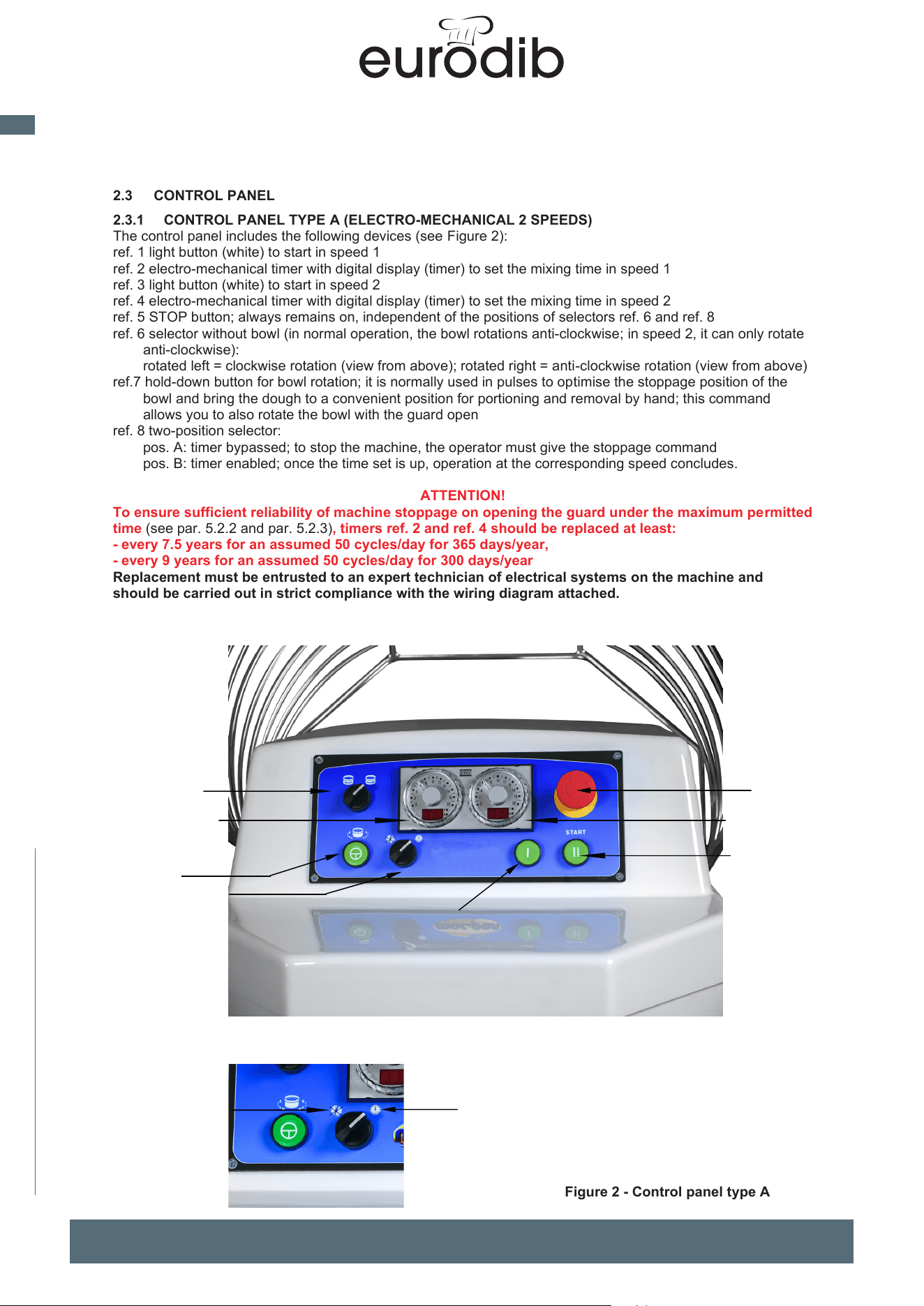
The main parts composing the machine are (see Figure 1):
ref. 1 base frame
ref. 2 bowl
ref. 3 spiral arm (mixing tool); based on the machine and panel ref. 7 supply, it can rotate at
- two different
speeds , identified with: speed 1 (lower) and speed 2 (higher)
ref. 4 central tool
ref. 5 bowl guard; can be a full type (an opening only to add ingredients) or “grid” type, i.e. with numerous
openings (only possible for machines not CE marked)
ref. 6 cover
ref. 7 control panel; according to how the machine is ordered, it can be the following types:
A)
electro-mechanical panel (par. 2.3.1)
r
ef. 8 compartment containing the electric box; it is inside the base frame
ref. 9 main electricity switch lockable in position O - OFF (for example with a lock)
The machine is equipped with two motors, hosted inside the base frame, one of which drives rotation of the tool
(spiral arm) and the other drives the bowl.
Figure 1 - Main parts of the machine
4
3
2
2
7
8
9
1
5
6
MADE IN ITALY
10
EN
spiral mixer xed bowl
11
2.3 CONTROL PANEL
2.3.1 CONTROL PANEL TYPE A (ELECTRO-MECHANICAL 2 SPEEDS)
The control panel includes the following devices (see Figure 2):
ref. 1 light button (white) to start in speed 1
ref. 2 electro-mechanical timer with digital display (timer) to set the mixing time in speed 1
ref. 3 light button (white) to start in speed 2
ref. 4 electro-mechanical timer with digital display (timer) to set the mixing time in speed 2
ref. 5 STOP button; always remains on, independent of the positions of selectors ref. 6 and ref. 8
ref. 6 selector without bowl (in normal operation, the bowl rotations anti-clockwise; in speed 2, it can only rotate
anti-clockwise):
rotated left = clockwise rotation (view from above); rotated right = anti-clockwise rotation (view from above)
ref.7 hold-down button for bowl rotation; it is normally used in pulses to optimise the stoppage position of the
bowl and bring the dough to a convenient position for portioning and removal by hand; this command
allows you to also rotate the bowl with the guard open
ref. 8 two-position selector:
pos. A: timer bypassed; to stop the machine, the operator must give the stoppage command
pos. B: timer enabled; once the time set is up, operation at the corresponding speed concludes.
ATTENTION!
To ensure sufficient reliability of machine stoppage on opening the guard under the maximum permitted
time (see par. 5.2.2 and par. 5.2.3), timers ref. 2 and ref. 4 should be replaced at least:
- every 7.5 years for an assumed 50 cycles/day for 365 days/year,
- every 9 years for an assumed 50 cycles/day for 300 days/year
Replacement must be entrusted to an expert technician of electrical systems on the machine and
should be carried out in strict compliance with the wiring diagram attached.
Figure 2 - Control panel type A
3
1
2
4
6
7
5
8
A
B
MADE IN ITALY
11
EN
spiral mixer xed bowl
20
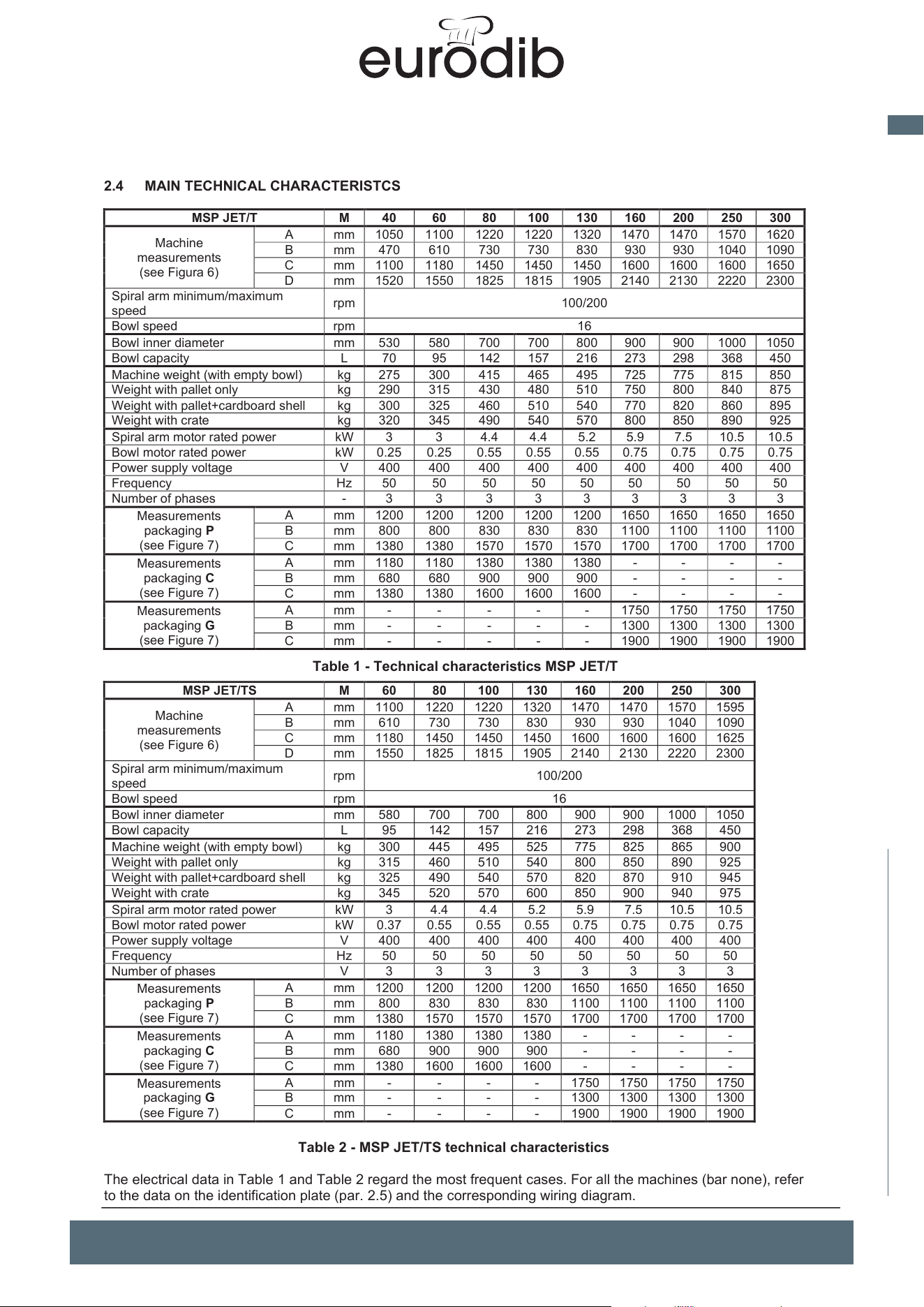
2.4 MAIN TECHNICAL CHARACTERISTCS
MSP JET/T
M
40
60
80
100
130
160
200
250
300
Machine
measurements
(see Figura 6)
A
mm
1050
1100
1220
1220
1320
1470
1470
1570
1620
B
mm
470
610
730
730
830
930
930
1040
1090
C
mm
1100
1180
1450
1450
1450
1600
1600
1600
1650
D
mm
1520
1550
1825
1815
1905
2140
2130
2220
2300
Spiral arm minimum/maximum
speed
rpm 100/200
Bowl speed
rpm
16
Bowl inner diameter
mm
530
580
700
700
800
900
900
1000
1050
Bowl capacity
L
70
95
142
157
216
273
298
368
450
Machine weight (with empty bowl)
kg
275
300
415
465
495
725
775
815
850
Weight with pallet only
kg
290
315
430
480
510
750
800
840
875
Weight with pallet+cardboard shell
kg
300
325
460
510
540
770
820
860
895
Weight with crate
kg
320
345
490
540
570
800
850
890
925
Spiral arm motor rated power
kW
3
3
4.4
4.4
5.2
5.9
7.5
10.5
10.5
Bowl motor rated power
kW
0.25
0.25
0.55
0.55
0.55
0.75
0.75
0.75
0.75
Power supply voltage
V
400
400
400
400
400
400
400
400
400
Frequency
Hz
50
50
50
50
50
50
50
50
50
Number of phases
-
3
3
3
3
3
3
3
3
3
Measurements
packaging P
(see Figure 7)
A
mm
1200
1200
1200
1200
1200
1650
1650
1650
1650
B
mm
800
800
830
830
830
1100
1100
1100
1100
C
mm
1380
1380
1570
1570
1570
1700
1700
1700
1700
Measurements
packaging C
(see Figure 7)
A
mm
1180
1180
1380
1380
1380
-
-
-
-
B
mm
680
680
900
900
900
-
-
-
-
C
mm
1380
1380
1600
1600
1600
-
-
-
-
Measurements
packaging G
(see Figure 7)
A
mm
-
-
-
-
-
1750
1750
1750
1750
B
mm
-
-
-
-
-
1300
1300
1300
1300
C
mm
-
-
-
-
-
1900
1900
1900
1900
Table 1 - Technical characteristics MSP JET/T
MSP JET/TS
M
60
80
100
130
160
200
250
300
Machine
measurements
(see Figure 6)
A
mm
1100
1220
1220
1320
1470
1470
1570
1595
B
mm
610
730
730
830
930
930
1040
1090
C
mm
1180
1450
1450
1450
1600
1600
1600
1625
D
mm
1550
1825
1815
1905
2140
2130
2220
2300
Spiral arm minimum/maximum
speed
rpm 100/200
Bowl speed
rpm
16
Bowl inner diameter
mm
580
700
700
800
900
900
1000
1050
Bowl capacity
L
95
142
157
216
273
298
368
450
Machine weight (with empty bowl)
kg
300
445
495
525
775
825
865
900
Weight with pallet only
kg
315
460
510
540
800
850
890
925
Weight with pallet+cardboard shell
kg
325
490
540
570
820
870
910
945
Weight with crate
kg
345
520
570
600
850
900
940
975
Spiral arm motor rated power
kW
3
4.4
4.4
5.2
5.9
7.5
10.5
10.5
Bowl motor rated power
kW
0.37
0.55
0.55
0.55
0.75
0.75
0.75
0.75
Power supply voltage
V
400
400
400
400
400
400
400
400
Frequency
Hz
50
50
50
50
50
50
50
50
Number of phases
V
3
3
3
3
3
3
3
3
Measurements
packaging P
(see Figure 7)
A
mm
1200
1200
1200
1200
1650
1650
1650
1650
B
mm
800
830
830
830
1100
1100
1100
1100
C
mm
1380
1570
1570
1570
1700
1700
1700
1700
Measurements
packaging C
(see Figure 7)
A
mm
1180
1380
1380
1380
-
-
-
-
B
mm
680
900
900
900
-
-
-
-
C
mm
1380
1600
1600
1600
-
-
-
-
Measurements
packaging G
(see Figure 7)
A
mm
-
-
-
-
1750
1750
1750
1750
B
mm
-
-
-
-
1300
1300
1300
1300
C
mm
-
-
-
-
1900
1900
1900
1900
Table 2 - MSP JET/TS technical characteristics
The electrical data in Table 1 and Table 2 regard the most frequent cases. For all the machines (bar none), refer
to the data on the identification plate (par. 2.5) and the corresponding wiring diagram.
UNIMIX and SUPREME Spiral Mixers Use and maintenance instructions (translation of original instructions) - Ed. 01/2019
EFFEDUE S.R.L. Via dell’Artigianato, 10 36034 MALO (VI) - I
21
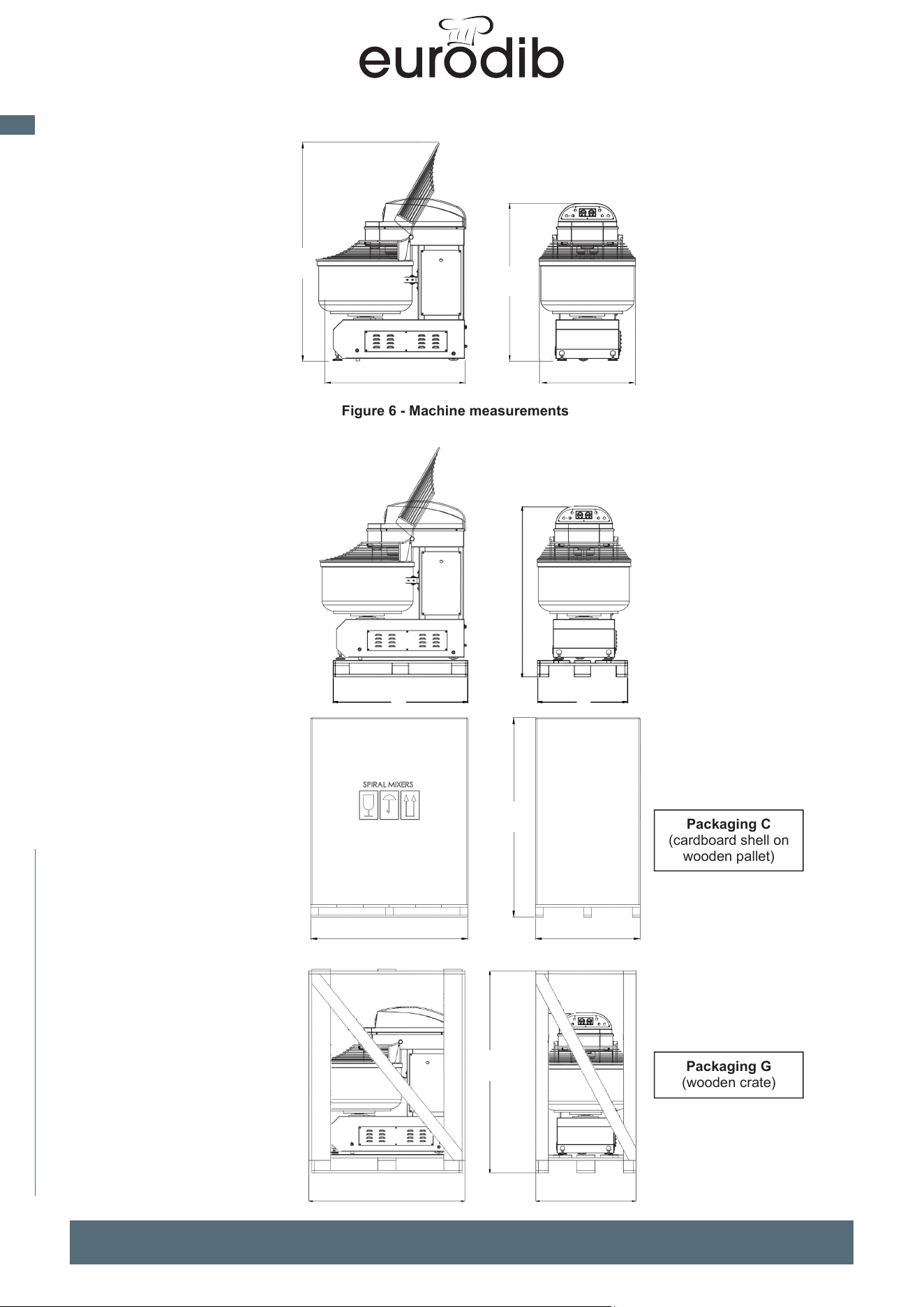
Figure 6 - Machine measurements
Figure 7 - Packaging dimensions
B
A
C
D
Packaging P
(wooden pallet only)
B
A
C
Packaging C
(cardboard shell on
wooden pallet)
Packaging G
(wooden crate)
B
A
C
B
A
C
MADE IN ITALY
12
EN
spiral mixer xed bowl
UNIMIX and SUPREME Spiral Mixers Use and maintenance instructions (translation of original instructions) - Ed. 01/2019
EFFEDUE S.R.L. Via dell’Artigianato, 10 36034 MALO (VI) - I
20
2.4 MAIN TECHNICAL CHARACTERISTCS
UNIMIX
M
40
60
80
100
130
160
200
250
300
Machine
measurements
(see Figura 6)
A
mm
1050
1100
1220
1220
1320
1470
1470
1570
1620
B
mm
470
610
730
730
830
930
930
1040
1090
C
mm
1100
1180
1450
1450
1450
1600
1600
1600
1650
D
mm
1520
1550
1825
1815
1905
2140
2130
2220
2300
Spiral arm minimum/maximum
speed
rpm
100/200
Bowl speed
rpm
16
Bowl inner diameter
mm
530
580
700
700
800
900
900
1000
1050
Bowl capacity
L
70
95
142
157
216
273
298
368
450
Machine weight (with empty bowl)
kg
275
300
415
465
495
725
775
815
850
Weight with pallet only
kg
290
315
430
480
510
750
800
840
875
Weight with pallet+cardboard shell
kg
300
325
460
510
540
770
820
860
895
Weight with crate
kg
320
345
490
540
570
800
850
890
925
Spiral arm motor rated power
kW
3
3
4.4
4.4
5.2
5.9
7.5
10.5
10.5
Bowl motor rated power
kW
0.25
0.25
0.55
0.55
0.55
0.75
0.75
0.75
0.75
Power supply voltage
V
400
400
400
400
400
400
400
400
400
Frequency
Hz
50
50
50
50
50
50
50
50
50
Number of phases
-
3
3
3
3
3
3
3
3
3
Measurements
packaging P
(see Figure 7)
A
mm
1200
1200
1200
1200
1200
1650
1650
1650
1650
B
mm
800
800
830
830
830
1100
1100
1100
1100
C
mm
1380
1380
1570
1570
1570
1700
1700
1700
1700
Measurements
packaging C
(see Figure 7)
A
mm
1180
1180
1380
1380
1380
-
-
-
-
B
mm
680
680
900
900
900
-
-
-
-
C
mm
1380
1380
1600
1600
1600
-
-
-
-
Measurements
packaging G
(see Figure 7)
A
mm
-
-
-
-
-
1750
1750
1750
1750
B
mm
-
-
-
-
-
1300
1300
1300
1300
C
mm
-
-
-
-
-
1900
1900
1900
1900
Table 1 - Technical characteristics UNIMIX
SUPREME
M
60
80
100
130
160
200
250
300
Machine
measurements
(see Figure 6)
A
mm
1100
1220
1220
1320
1470
1470
1570
1595
B
mm
610
730
730
830
930
930
1040
1090
C
mm
1180
1450
1450
1450
1600
1600
1600
1625
D
mm
1550
1825
1815
1905
2140
2130
2220
2300
Spiral arm minimum/maximum
speed
rpm
100/200
Bowl speed
rpm
16
Bowl inner diameter
mm
580
700
700
800
900
900
1000
1050
Bowl capacity
L
95
142
157
216
273
298
368
450
Machine weight (with empty bowl)
kg
300
445
495
525
775
825
865
900
Weight with pallet only
kg
315
460
510
540
800
850
890
925
Weight with pallet+cardboard shell
kg
325
490
540
570
820
870
910
945
Weight with crate
kg
345
520
570
600
850
900
940
975
Spiral arm motor rated power
kW
3
4.4
4.4
5.2
5.9
7.5
10.5
10.5
Bowl motor rated power
kW
0.37
0.55
0.55
0.55
0.75
0.75
0.75
0.75
Power supply voltage
V
400
400
400
400
400
400
400
400
Frequency
Hz
50
50
50
50
50
50
50
50
Number of phases
V
3
3
3
3
3
3
3
3
Measurements
packaging P
(see Figure 7)
A
mm
1200
1200
1200
1200
1650
1650
1650
1650
B
mm
800
830
830
830
1100
1100
1100
1100
C
mm
1380
1570
1570
1570
1700
1700
1700
1700
Measurements
packaging C
(see Figure 7)
A
mm
1180
1380
1380
1380
-
-
-
-
B
mm
680
900
900
900
-
-
-
-
C
mm
1380
1600
1600
1600
-
-
-
-
Measurements
packaging G
(see Figure 7)
A
mm
-
-
-
-
1750
1750
1750
1750
B
mm
-
-
-
-
1300
1300
1300
1300
C
mm
-
-
-
-
1900
1900
1900
1900
Table 2 - SUPREME technical characteristics
The electrical data in Table 1 and Table 2 regard the most frequent cases. For all the machines (bar none), refer
to the data on the identification plate (par. 2.5) and the corresponding wiring diagram.
21
Figure 6 - Machine measurements
Figure 7 - Packaging dimensions
Packaging C
(cardboard shell on
wooden pallet)
Packaging G
(wooden crate)
B
A
C
D
C
A
B
B
A
C
C
MADE IN ITALY
13
EN
spiral mixer xed bowl
22
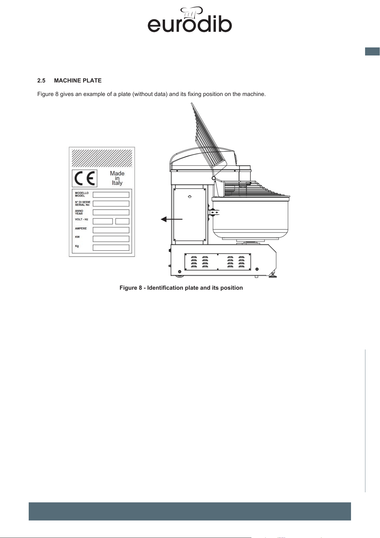
2.5 MACHINE PLATE
Figure 8 gives an example of a plate (without data) and its fixing position on the machine.
Figure 8 - Identification plate and its position
UNIMIX and SUPREME Spiral Mixers Use and maintenance instructions (translation of original instructions) - Ed. 01/2019
EFFEDUE S.R.L. Via dell’Artigianato, 10 36034 MALO (VI) - I
23
3 INSTALLATION AND USE
3.1 WARNINGS FOR THE INSTALLATION PREMISES
The location in which the machine will be held and/or used must comply with legislation in force to ensure
adequate protection against atmospheric agents, as well as damage, deterioration, etc. The access routes must
allow easy passage of the machine, without risk for personal safety and safety of the machine. Flooring, support
structures and walls must comply with legislation and standards in force, and must be suitable to support the
overall load with an adequate safety coefficient; they must be easy to clean, disinfect and disinfest. The flooring
must be flat, not sloped, compact and without holes and roughness.
The electrical system and the equipotential protection system (ground) on site must comply with legislation and
standards in force, as well as being installed, maintained and, if outlined by law, checked by authorised and
professionally qualified technicians, able to issue any Declaration of Conformity.
The power supply panel upstream must have suitable safety devices against current overloads, short circuits
and phase-phase, phase-neutral (if relevant) and phase-ground faults.
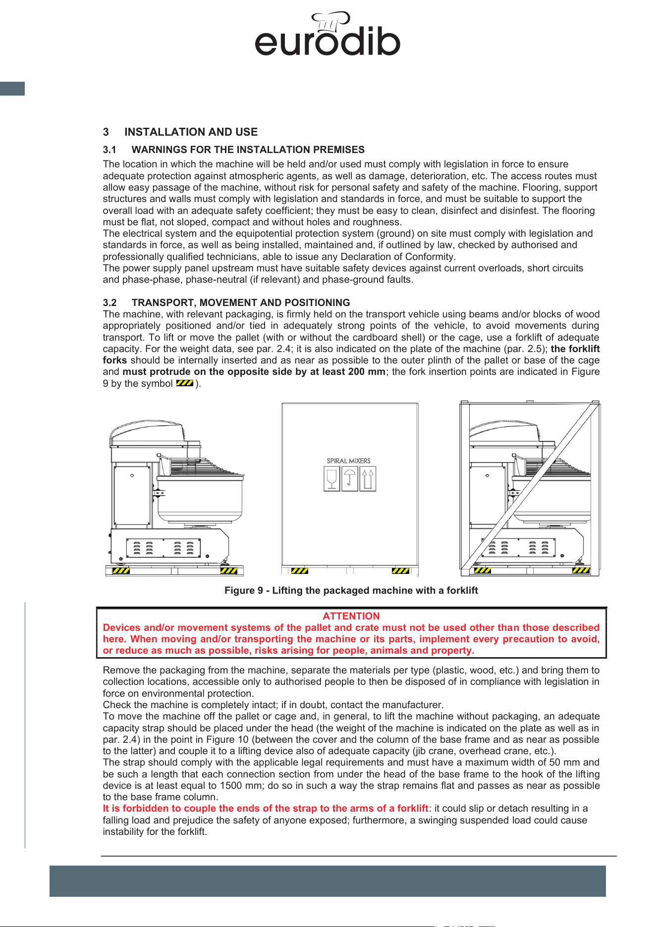
3.2 TRANSPORT, MOVEMENT AND POSITIONING
The machine, with relevant packaging, is firmly held on the transport vehicle using beams and/or blocks of wood
appropriately positioned and/or tied in adequately strong points of the vehicle, to avoid movements during
transport. To lift or move the pallet (with or without the cardboard shell) or the cage, use a forklift of adequate
capacity. For the weight data, see par. 2.4; it is also indicated on the plate of the machine (par. 2.5); the forklift
forks should be internally inserted and as near as possible to the outer plinth of the pallet or base of the cage
and must protrude on the opposite side by at least 200 mm; the fork insertion points are indicated in Figure
9 by the symbol ).
Figure 9 - Lifting the packaged machine with a forklift
ATTENTION
Devices and/or movement systems of the pallet and crate must not be used other than those described
here. When moving and/or transporting the machine or its parts, implement every precaution to avoid,
or reduce as much as possible, risks arising for people, animals and property.
Remove the packaging from the machine, separate the materials per type (plastic, wood, etc.) and bring them to
collection locations, accessible only to authorised people to then be disposed of in compliance with legislation in
force on environmental protection.
Check the machine is completely intact; if in doubt, contact the manufacturer.
To move the machine off the pallet or cage and, in general, to lift the machine without packaging, an adequate
capacity strap should be placed under the head (the weight of the machine is indicated on the plate as well as in
par. 2.4) in the point in Figure 10 (between the cover and the column of the base frame and as near as possible
to the latter) and couple it to a lifting device also of adequate capacity (jib crane, overhead crane, etc.).
The strap should comply with the applicable legal requirements and must have a maximum width of 50 mm and
be such a length that each connection section from under the head of the base frame to the hook of the lifting
device is at least equal to 1500 mm; do so in such a way the strap remains flat and passes as near as possible
to the base frame column.
It is forbidden to couple the ends of the strap to the arms of a forklift: it could slip or detach resulting in a
falling load and prejudice the safety of anyone exposed; furthermore, a swinging suspended load could cause
instability for the forklift.
MADE IN ITALY
14
EN
spiral mixer xed bowl
UNIMIX and SUPREME Spiral Mixers Use and maintenance instructions (translation of original instructions) - Ed. 01/2019
EFFEDUE S.R.L. Via dell’Artigianato, 10 36034 MALO (VI) - I
22
2.5 MACHINE PLATE
Figure 8 gives an example of a plate (without data) and its fixing position on the machine.
Figure 8 - Identification plate and its position
23
3 INSTALLATION AND USE
3.1 WARNINGS FOR THE INSTALLATION PREMISES
The location in which the machine will be held and/or used must comply with legislation in force to ensure
adequate protection against atmospheric agents, as well as damage, deterioration, etc. The access routes must
allow easy passage of the machine, without risk for personal safety and safety of the machine. Flooring, support
structures and walls must comply with legislation and standards in force, and must be suitable to support the
overall load with an adequate safety coefficient; they must be easy to clean, disinfect and disinfest. The flooring
must be flat, not sloped, compact and without holes and roughness.
The electrical system and the equipotential protection system (ground) on site must comply with legislation and
standards in force, as well as being installed, maintained and, if outlined by law, checked by authorised and
professionally qualified technicians, able to issue any Declaration of Conformity.
The power supply panel upstream must have suitable safety devices against current overloads, short circuits
and phase-phase, phase-neutral (if relevant) and phase-ground faults.
3.2 TRANSPORT, MOVEMENT AND POSITIONING
The machine, with relevant packaging, is firmly held on the transport vehicle using beams and/or blocks of wood
appropriately positioned and/or tied in adequately strong points of the vehicle, to avoid movements during
transport. To lift or move the pallet (with or without the cardboard shell) or the cage, use a forklift of adequate
capacity. For the weight data, see par. 2.4; it is also indicated on the plate of the machine (par. 2.5); the forklift
forks should be internally inserted and as near as possible to the outer plinth of the pallet or base of the cage
and must protrude on the opposite side by at least 200 mm; the fork insertion points are indicated in Figure
9 by the symbol ).
Figure 9 - Lifting the packaged machine with a forklift
ATTENTION
Devices and/or movement systems of the pallet and crate must not be used other than those described
here. When moving and/or transporting the machine or its parts, implement every precaution to avoid,
or reduce as much as possible, risks arising for people, animals and property.
Remove the packaging from the machine, separate the materials per type (plastic, wood, etc.) and bring them to
collection locations, accessible only to authorised people to then be disposed of in compliance with legislation in
force on environmental protection.
Check the machine is completely intact; if in doubt, contact the manufacturer.
To move the machine off the pallet or cage and, in general, to lift the machine without packaging, an adequate
capacity strap should be placed under the head (the weight of the machine is indicated on the plate as well as in
par. 2.4) in the point in Figure 10 (between the cover and the column of the base frame and as near as possible
to the latter) and couple it to a lifting device also of adequate capacity (jib crane, overhead crane, etc.).
The strap should comply with the applicable legal requirements and must have a maximum width of 50 mm and
be such a length that each connection section from under the head of the base frame to the hook of the lifting
device is at least equal to 1500 mm; do so in such a way the strap remains flat and passes as near as possible
to the base frame column.
It is forbidden to couple the ends of the strap to the arms of a forklift: it could slip or detach resulting in a
falling load and prejudice the safety of anyone exposed; furthermore, a swinging suspended load could cause
instability for the forklift.
MADE IN ITALY
15
EN
spiral mixer xed bowl
24
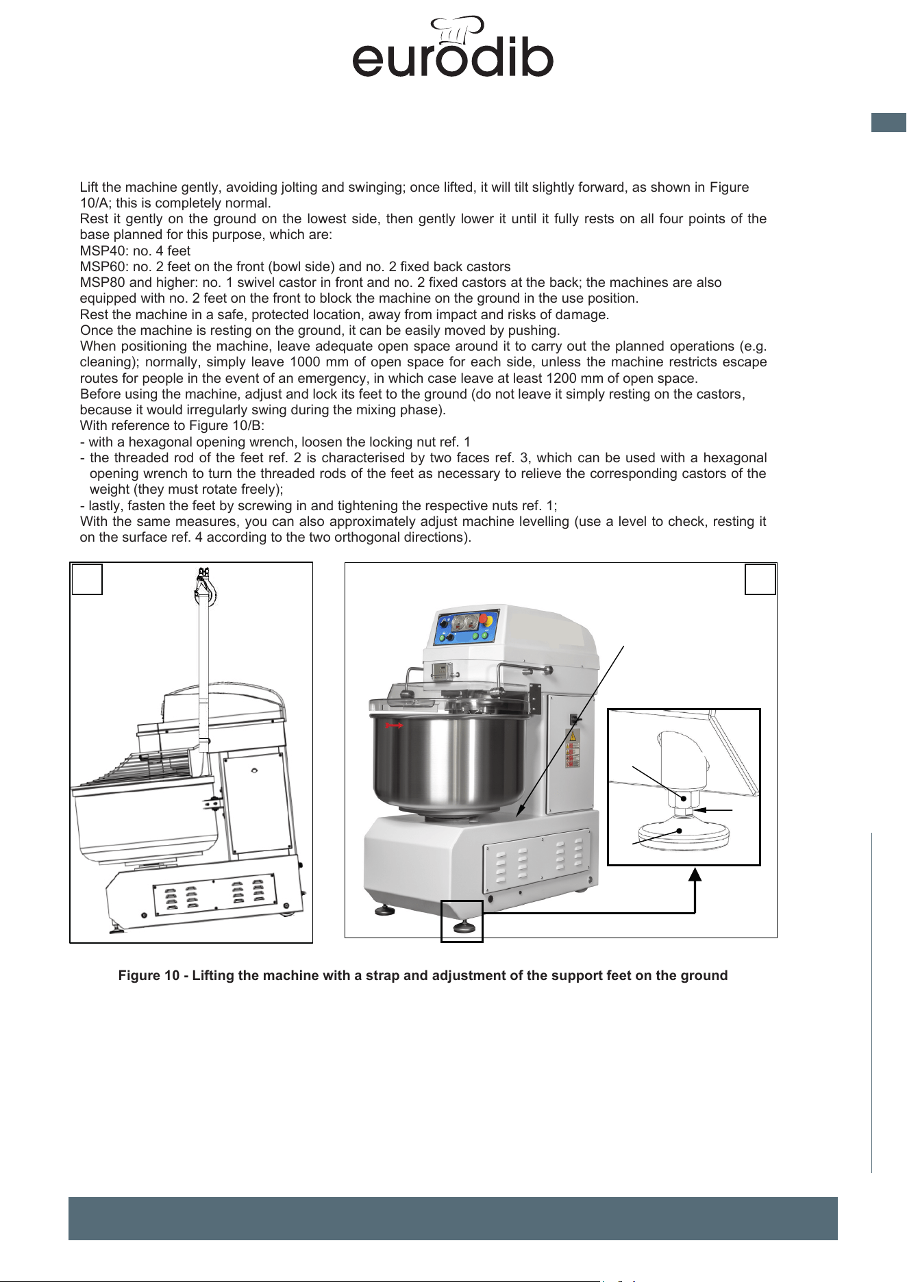
Lift the machine gently, avoiding jolting and swinging; once lifted, it will tilt slightly forward, as shown in Figure
10/A; this is completely normal.
Rest it gently on the ground on the lowest side, then gently lower it until it fully rests on all four points of the
base planned for this purpose, which are:
MSP40: no. 4 feet
MSP60: no. 2 feet on the front (bowl side) and no. 2 fixed back castors
MSP80 and higher: no. 1 swivel castor in front and no. 2 fixed castors at the back; the machines are also
equipped with no. 2 feet on the front to block the machine on the ground in the use position.
Rest the machine in a safe, protected location, away from impact and risks of damage.
Once the machine is resting on the ground, it can be easily moved by pushing.
When positioning the machine, leave adequate open space around it to carry out the planned operations (e.g.
cleaning); normally, simply leave 1000 mm of open space for each side, unless the machine restricts escape
routes for people in the event of an emergency, in which case leave at least 1200 mm of open space.
Before using the machine, adjust and lock its feet to the ground (do not leave it simply resting on the castors,
because it would irregularly swing during the mixing phase).
With reference to Figure 10/B:
- with a hexagonal opening wrench, loosen the locking nut ref. 1
- the
threaded rod of the feet ref. 2 is characterised by two faces ref. 3, which can be used with a hexagonal
opening wrench to turn the threaded rods of the feet as necessary to relieve the corresponding castors of the
weight (they must rotate freely);
- lastly, fasten the feet by screwing in and tightening the respective nuts ref. 1
;
W
ith the same measures, you can also approximately adjust machine levelling (use a level to check, resting it
on the surface ref. 4 according to the two orthogonal directions).
Figure 10 - Lifting the machine with a strap and adjustment of the support feet on the ground
UNIMIX and SUPREME Spiral Mixers Use and maintenance instructions (translation of original instructions) - Ed. 01/2019
EFFEDUE S.R.L. Via dell’Artigianato, 10 36034 MALO (VI) - I
25
3.3 ELECTRICAL CONNECTION
Every intervention of an electrical nature relevant to the workplace must be carried out by specialist and expert
technicians who have the technical and legislative know-how to carry out works to standard and safely in
compliance with legislation and standards in force; they should issue a possible Declaration of Conformity
pursuant to legislation. On delivery of the machine and however before proceeding to electrical connection,
ensure the voltage, frequency and number of phases of the electrical power line are the same as those
declared by the manufacturer and indicated on the identification plate (par. 2.5) and on the relevant wiring
diagram attached.
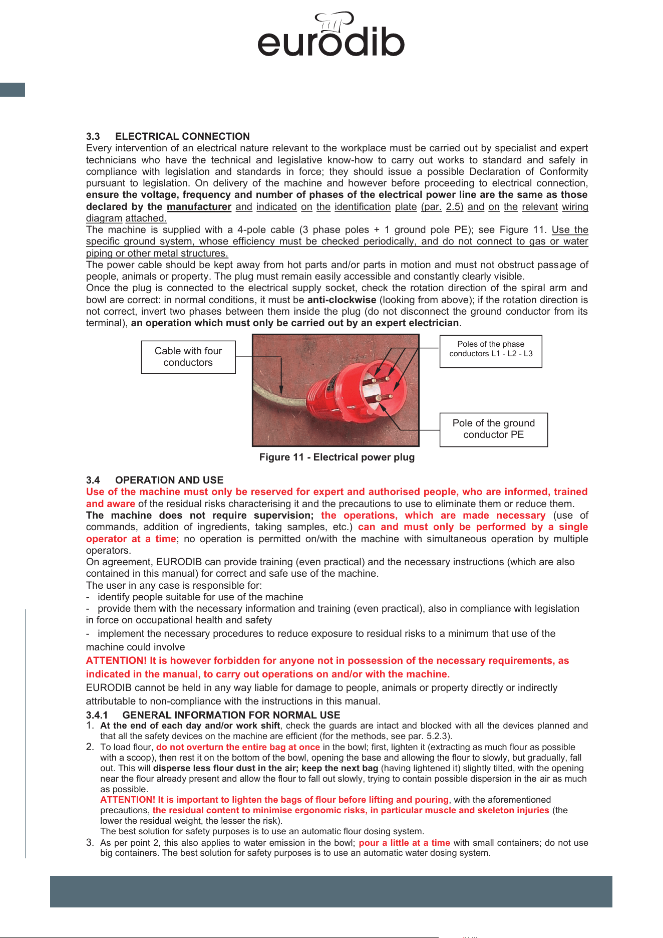
The machine is supplied with a 4-pole cable (3 phase poles + 1 ground pole PE); see Figure 11. Use the
specific ground system, whose efficiency must be checked periodically, and do not connect to gas or water
piping or other metal structures.
The power cable should be kept away from hot parts and/or parts in motion and must not obstruct passage of
people, animals or property. The plug must remain easily accessible and constantly clearly visible.
Once the plug is connected to the electrical supply socket, check the rotation direction of the spiral arm and
bowl are correct: in normal conditions, it must be anti-clockwise (looking from above); if the rotation direction is
not correct, invert two phases between them inside the plug (do not disconnect the ground conductor from its
terminal), an operation which must only be carried out by an expert electrician.
Figure 11 - Electrical power plug
3.4 OPERATION AND USE
Use of the machine must only be reserved for expert and authorised people, who are informed, trained
and aware of the residual risks characterising it and the precautions to use to eliminate them or reduce them.
The machine does not require supervision; the operations, which are made necessary (use of
commands, addition of ingredients, taking samples, etc.) can and must only be performed by a single
operator at a time; no operation is permitted on/with the machine with simultaneous operation by multiple
operators.
On agreement, EFFEDUE can provide training (even practical) and the necessary instructions (which are also
contained in this manual) for correct and safe use of the machine.
The user in any case is responsible for:
- identify people suitable for use of the machine
- provide them with the necessary information and training (even practical), also in compliance with legislation in
force on occupational health and safety
- implement the necessary procedures to reduce exposure to residual risks to a minimum that use of the
machine could involve
ATTENTION! It is however forbidden for anyone not in possession of the necessary requirements, as
indicated in the manual, to carry out operations on and/or with the machine.
EFFEDUE cannot be held in any way liable for damage to people, animals or property directly or indirectly
attributable to non-compliance with the instructions in this manual.
3.4.1 GENERAL INFORMATION FOR NORMAL USE
1.
At the end of each day and/or work shift, check the guards are intact and blocked with all the devices planned and
that all the safety devices on the machine are efficient (for the methods, see par. 5.2.3).
2. To load flour, do not overturn the entire bag at once in the bowl; first, lighten it (extracting as much flour as possible
with a scoop), then rest it on the bottom of the bowl, opening the base and allowing the flour to slowly, but gradually, fall
out. This will disperse less flour dust in the air; keep the next bag (having lightened it) slightly tilted, with the opening
near the flour already present and allow the flour to fall out slowly, trying to contain possible dispersion in the air as much
as possible.
ATTENTION! It is important to lighten the bags of flour before lifting and pouring, with the aforementioned
precautions, the residual content to minimise ergonomic risks, in particular muscle and skeleton injuries (the
lower the residual weight, the lesser the risk).
The best solution for safety purposes is to use an automatic flour dosing system.
3. As per point 2, this also applies to water emission in the bowl; pour a little at a time with small containers; do not use
big containers. The best solution for safety purposes is to use an automatic water dosing system.
Pole of the ground
conductor PE
Poles of the phase
conductors L1 - L2 - L3
Cable with four
conductors
1
B A
3
2
4
MADE IN ITALY
16
EN
spiral mixer xed bowl
UNIMIX and SUPREME Spiral Mixers Use and maintenance instructions (translation of original instructions) - Ed. 01/2019
EFFEDUE S.R.L. Via dell’Artigianato, 10 36034 MALO (VI) - I
24
Lift the machine gently, avoiding jolting and swinging; once lifted, it will tilt slightly forward, as shown in Figure
10/A; this is completely normal.
Rest it gently on the ground on the lowest side, then gently lower it until it fully rests on all four points of the
base planned for this purpose, which are:
M40: no. 4 feet
M60: no. 2 feet on the front (bowl side) and no. 2 fixed back castors
M80 and higher: no. 1 swivel castor in front and no. 2 fixed castors at the back; the machines are also equipped
with no. 2 feet on the front to block the machine on the ground in the use position.
Rest the machine in a safe, protected location, away from impact and risks of damage.
Once the machine is resting on the ground, it can be easily moved by pushing.
When positioning the machine, leave adequate open space around it to carry out the planned operations (e.g.
cleaning); normally, simply leave 1000 mm of open space for each side, unless the machine restricts escape
routes for people in the event of an emergency, in which case leave at least 1200 mm of open space.
Before using the machine, adjust and lock its feet to the ground (do not leave it simply resting on the castors,
because it would irregularly swing during the mixing phase).
With reference to Figure 10/B:
- with a hexagonal opening wrench, loosen the locking nut ref. 1
- the threaded rod of the feet ref. 2 is characterised by two faces ref. 3, which can be used with a hexagonal
opening wrench to turn the threaded rods of the feet as necessary to relieve the corresponding castors of the
weight (they must rotate freely);
- lastly, fasten the feet by screwing in and tightening the respective nuts ref. 1;
With the same measures, you can also approximately adjust machine levelling (use a level to check, resting it
on the surface ref. 4 according to the two orthogonal directions).
Figure 10 - Lifting the machine with a strap and adjustment of the support feet on the ground
1
B
A
3
2
4
25
3.3 ELECTRICAL CONNECTION
Every intervention of an electrical nature relevant to the workplace must be carried out by specialist and expert
technicians who have the technical and legislative know-how to carry out works to standard and safely in
compliance with legislation and standards in force; they should issue a possible Declaration of Conformity
pursuant to legislation. On delivery of the machine and however before proceeding to electrical connection,
ensure the voltage, frequency and number of phases of the electrical power line are the same as those
declared by the manufacturer and indicated on the identification plate (par. 2.5) and on the relevant wiring
diagram attached.
The machine is supplied with a 4-pole cable (3 phase poles + 1 ground pole PE); see Figure 11. Use the
specific ground system, whose efficiency must be checked periodically, and do not connect to gas or water
piping or other metal structures.
The power cable should be kept away from hot parts and/or parts in motion and must not obstruct passage of
people, animals or property. The plug must remain easily accessible and constantly clearly visible.
Once the plug is connected to the electrical supply socket, check the rotation direction of the spiral arm and
bowl are correct: in normal conditions, it must be anti-clockwise (looking from above); if the rotation direction is
not correct, invert two phases between them inside the plug (do not disconnect the ground conductor from its
terminal), an operation which must only be carried out by an expert electrician.
Figure 11 - Electrical power plug
3.4 OPERATION
AND USE
Use of the machine must only be reserved for expert and authorised people, who are informed, trained
and aware of the residual risks characterising it and the precautions to use to eliminate them or reduce them.
The machine does not require supervision; the operations, which are made necessary (use of
commands, addition of ingredients, taking samples, etc.) can and must only be performed by a single
operator at a time; no operation is permitted on/with the machine with simultaneous operation by multiple
operators.
On agreement, EURODIB can provide training (even practical) and the necessary instructions (which are also
contained in this manual) for correct and safe use of the machine.
The user in any case is responsible for:
- identify people suitable for use of the machine
- provide them with the necessary information and training (even practical), also in compliance with legislation
in force on occupational health and safety
- implement the necessary procedures to reduce exposure to residual risks to a minimum that use of the
machine could involve
ATTENTION! It is however forbidden for anyone not in possession of the necessary requirements, as
indicated in the manual, to carry out operations on and/or with the machine.
EURODIB cannot be held in any way liable for damage to people, animals or property directly or indirectly
attributable to non-compliance with the instructions in this manual.
3.4.1 GENERAL INFORMATION FOR NORMAL USE
1.
At the end of each day and/or work shift, check the guards are intact and blocked with all the devices planned and
that all the safety devices on the machine are efficient (for the methods, see par. 5.2.3).
2. To load flour, do not overturn the entire bag at once in the bowl; first, lighten it (extracting as much flour as possible
with a scoop), then rest it on the bottom of the bowl, opening the base and allowing the flour to slowly, but gradually, fall
out. This will disperse less flour dust in the air; keep the next bag (having lightened it) slightly tilted, with the opening
near the flour already present and allow the flour to fall out slowly, trying to contain possible dispersion in the air as much
as possible.
ATTENTION! It is important to lighten the bags of flour before lifting and pouring, with the aforementioned
precautions, the residual content to minimise ergonomic risks, in particular muscle and skeleton injuries (the
lower the residual weight, the lesser the risk).
The best solution for safety purposes is to use an automatic flour dosing system.
3. As per point 2, this also applies to water emission in the bowl; pour a little at a time with small containers; do not use
big containers. The best solution for safety purposes is to use an automatic water dosing system.
Pole of the ground
conductor PE
Poles of the phase
conductors L1 - L2 - L3
Cable with four
conductors
MADE IN ITALY
17
EN
spiral mixer xed bowl
26
4. For routine use of the machine, the operator must wear safety shoes with reinforced caps; no further PPE
are necessary, unless this necessity arises from the health and safety risk assessment which must be carried
out by the employer (remember this assessment is compulsory, according to European Union legislation in
force). If, for
example, the aforementioned instructions are ignored and entire bags of flour are poured into
the
bowl, lots of dust would inevitably develop which would expose the operator and people nearby to the health
risk of inhalation (rhinitis, asthma,
lacrimation, etc.); in this case, the employer and the operator will
be
exclusively responsible for implementing every
possible measure to eliminate or minimise any risk for
the
health and
safety of people, animals or property, caused directly or indirectly by air-borne dust development
in
the environment (for example, before pouring the flour, it should
be checked that there is nobody near
the
machine and at
least wear a mask to protect the airways with adequate filtering power for the grain size of
the
flour (indicated on the technical data sheet, if available,
or through measurements taken by the
employer for
the purposes of the aforementioned risk assessment).
The employer is responsible for identifying additional
PPE, if necessary (for example, to safeguard
food
hygiene).
5. If
the machine is equipped with a grid guard on the bowl, rotate the spiral arm at speed 1 until all the flour is
blended with the water and only then go to speed 2; this is an excellent tip to limit flour dust dispersion
caused by movement of the mixing tool.
6. Do not try to recover flour deposited on parts of the machine; it may be contaminated
and compromise the
purity and hygiene of the dough with resulting risk for consumers.
The operator could also be exposed to a
serious risk for his/her health if hands, fingers, etc. are placed
in
zone
s with parts in motion (e.g. between the sides of the bowl and the column or
between the interlocked
guard and the bowl).
7. To control normal stoppage, press the
STOP button or give the command using the specific icon on the touch
screen; other than stopping the machine, the command also causes the electrical energy of the motors to
reset to zero. The
STOP button, once pressed, must be reset to restart the machine.
8. If the interlocked guard placed over the bowl is lifted with the machine running (see par. 5.2.2, point
1), the
machine stops with electrical energy to the
motors reset to zero; in this case, to restart the machine,
firstly
close the guard and,
if the control panel is type C (TOUCH SCREEN, see par. 2.3.3) give
the RESET
command. In normal conditions, do not stop the machine by lifting the guard, also to avoid pointless
exposure to risks (see par. 5.2.4) and contribute to the longest possible duration of the safety system; rather
use the normal STOP button, as said in the previous point.
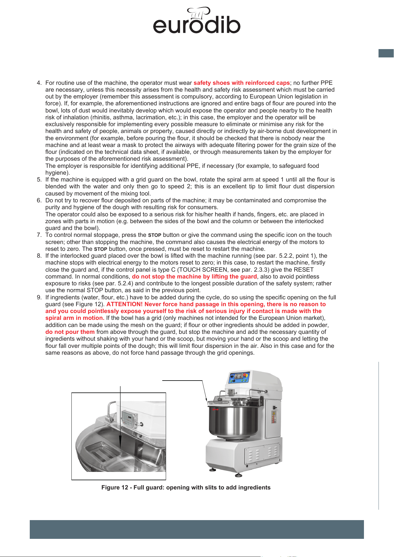
9. If ingredients (water, flour, etc.) have to be added during the cycle, do so using the specific opening on the full
guard (see Figure 12). ATTENTION!
Never force hand passage in this opening, there is no reason
to
and you could pointlessly expose yourself to the risk of serious injury
if contact is made with
the
spiral arm in motion. If the bowl has a grid (on
ly machines not intended for the European
Union market),
addition can be made using the mesh on the guard;
if flour or other ingredients should be added
in powder,
do not pour them from above through the guard, but stop the machine and add the necessary quantity of
ingredients without shaking with your hand or the scoop, but moving your hand or the scoop and letting
the
flour fall over multiple points of the dough; this will limit flour dispersion in the
air. Also in this case and for
the
same reasons as above, do not force hand passage through the grid openings.
F
igure 12 - Full guard: opening with slits to add ingredients
UNIMIX and SUPREME Spiral Mixers Use and maintenance instructions (translation of original instructions) - Ed. 01/2019
EFFEDUE S.R.L. Via dell’Artigianato, 10 36034 MALO (VI) - I
27
10.When cleaning the machine, at least wear shoes with a reinforced cap, waterproof gloves and an
adequate dustproof mask (for the appropriateness of the mask, see the previous point 4).
11.To remove dough from the bowl, get into a comfortable and accessible position and rotate the bowl with the
specific hold-down action, then sub-divide it into lightweight, small sized parts which would allow easy and
safe handling. The dough is not stable (the softer it is, the more unstable it is). It tends to drip downwards
and is difficult to hold in hands, unless in small portions; the centre of gravity of the mass varies continuously
and therefore causes continuous change in equilibrium and force that the operator must exert to maintain it.
If you consider that the operator must bend over to take the portion out, one can image the ergonomic risk
(possible muscle and skeleton injuries) increase as the weight of the portion removed by hand increases.
12.Do not place hands for any reason between the rotating bowl and the base frame, to avoid being exposed to
the residual risk of catching and dragging.
13.In speed 2, the bowl can only rotate anti-clockwise.
14.IMPORTANT! Before starting the machine, comply with the following instructions:
a) ensure the line voltage in the power socket corresponds to that indicated on the identification plate (par.
2.5) and on the relevant wiring diagram attached. On the contrary, do not proceed to electrical
connection and contact the supplier or the manufacturer.
b) check the rotation direction of the spiral arm is anti-clockwise (looking down from above), as indicated
by the arrow on the outer edge of the bowl; if this is not the case, invert the two phases in the plug at the
end of the cable supplied (also see par. 3.3)
3.4.2 SWITCHING ON AND OFF THE MACHINE
Having connected the plug to the socket of the electrical power supply, to switch on the machine, bring the main
switch ref. 9 Figure 1 to the position I - ON. For machines with a type C panel (Touch Screen F2), to start the
machine, firstly execute the RESET command (see par. 2.3.3)
To switch the machine off, bring the main switch ref. 9 Figure 1 to position O - OFF.
3.4.3 DOUGH PRODUCTION CYCLE
1. Place the ingredients in the bowl (with the caution described in par. 3.4.1, point 2) and close the bowl guard.
IMPORTANT! Do not put such a quantity of ingredients in the bowl that their total amount would
exceed the maximum capacity of the dough indicated by the manufacturer; this could cause serious
damage to machinery and, in particular, to the motion drive system.
The manufacturer cannot be held in any way liable for damage caused by non-compliance with the
aforementioned.
2. Close the main switch ref. 9 Figure 1, turning it ON - I
3. On the timers, set the operating times for speed 1 and for speed 2; to do this, for electro-mechanical timers,
turn the front castor until the red indicator is positioned on the desired time. Instead, for the touch screen, set
the desired times on the display (see par. 2.3.3 and par. 2.3.4)
4. With the machine set to automatic cycle mode, give the command to start for speed 1, if you want to execute
pre-mixing action at low speed to allow the ingredients to mutually bind and blend: when the time set is up for
speed 1, the mixing tool (spiral arm) will automatically go to speed 2 and will remain for the corresponding
time set, after this time is up the machine stops in standby for a new start. You can start from any speed
available, as well as change speed at any time during the cycle.
If the machine is set in manual operating mode (with the exception, therefore, of the machine equipped with
a control panel type B, see par. 2.3), the timers are disabled, therefore the operator must manually manage
passage from speed 1 to speed 2, and vice versa, controlling each stop and then giving the start command
for the desired speed.
ATTENTION! If the machine is equipped with a grid guard, do not start at speed 2 immediately, but
allow the machine to work at speed 1 for at least the time necessary to allow the flour in the bowl to
bind with the water and, in any case, for no less than 120 seconds; by doing so, development of
airborne flour is reduced and, as a result, the resulting risk for personal health.
5. If the guard is raised with the cycle in progress, the residual times of the cycle at the time of stoppage remain
saved. To restart the cycle from where it stopped, lower the guard and start again (for the panel with
electromechanical timer, press the relevant
START button for the speed running at time of stoppage).
6. During the mixing cycle, the rotation direction of the bowl can be rotated with the specific command device
(see par. 2.3; this can be useful, for example, to blend any “unmixed” flour in the dough, remaining on the
bottom of the bowl.
IMPORTANT! The rotation direction of the spiral arm during the normal mixing cycle must be anti-
clockwise (seen from above). If necessary, rotate the rotation direction of the bowl for the time
strictly necessary and reset the normal rotation direction as soon as possible; on the contrary,
damage to the machine could be caused, which could even be serious, due to irregular stress (mechanical
overloading of the drive units, overheating of the motor windings).
Opening with slits to add
ingredients
MADE IN ITALY
18
EN
spiral mixer xed bowl
UNIMIX and SUPREME Spiral Mixers Use and maintenance instructions (translation of original instructions) - Ed. 01/2019
EFFEDUE S.R.L. Via dell’Artigianato, 10 36034 MALO (VI) - I
26
4. For routine use of the machine, the operator must wear safety shoes with reinforced caps; no further PPE
are necessary, unless this necessity arises from the health and safety risk assessment which must be
carried out by the employer (remember this assessment is compulsory, according to European Union
legislation in force). If, for example, the aforementioned instructions are ignored and entire bags of flour are
poured into the bowl, lots of dust would inevitably develop which would expose the operator and people
nearby to the health risk of inhalation (rhinitis, asthma, lacrimation, etc.); in this case, the employer and the
operator will be exclusively responsible for implementing every possible measure to eliminate or minimise
any risk for the health and safety of people, animals or property, caused directly or indirectly by air-borne
dust development in the environment (for example, before pouring the flour, it should be checked that there
is nobody near the machine and at least wear a mask to protect the airways with adequate filtering power for
the grain size of the flour (indicated on the technical data sheet, if available, or through measurements taken
by the employer for the purposes of the aforementioned risk assessment).
The employer is responsible for identifying additional PPE, if necessary (for example, to safeguard food
hygiene).
5. If the machine is equipped with a grid guard on the bowl, rotate the spiral arm at speed 1 until all the flour is
blended with the water and only then go to speed 2; this is an excellent tip to limit flour dust dispersion
caused by movement of the mixing tool.
6. Do not try to recover flour deposited on parts of the machine; it may be contaminated and compromise the
purity and hygiene of the dough with resulting risk for consumers.
The operator could also be exposed to a serious risk for his/her health if hands, fingers, etc. are placed in
zones with parts in motion (e.g. between the sides of the bowl and the column or between the interlocked
guard and the bowl).
7. To control normal stoppage, press the STOP button or give the command using the specific icon on the touch
screen; other than stopping the machine, the command also causes the electrical energy of the motors to
reset to zero. The STOP button, once pressed, must be reset to restart the machine.
8. If the interlocked guard placed over the bowl is lifted with the machine running (see par. 5.2.2, point 1), the
machine stops with electrical energy to the motors reset to zero; in this case, to restart the machine, firstly
close the guard and, if the control panel is type C (TOUCH SCREEN F2, see par. 2.3.3) give the RESET
command. In normal conditions, do not stop the machine by lifting the guard, also to avoid pointless
exposure to risks (see par. 5.2.4) and contribute to the longest possible duration of the safety system; rather
use the normal STOP button, as said in the previous point.
9. If ingredients (water, flour, etc.) have to be added during the cycle, do so using the specific opening on the
full guard (see Figure 12). ATTENTION! Never force hand passage in this opening, there is no reason
to and you could pointlessly expose yourself to the risk of serious injury if contact is made with the
spiral arm in motion. If the bowl has a grid (only machines not intended for the European Union market),
addition can be made using the mesh on the guard; if flour or other ingredients should be added in powder,
do not pour them from above through the guard, but stop the machine and add the necessary quantity of
ingredients without shaking with your hand or the scoop, but moving your hand or the scoop and letting the
flour fall over multiple points of the dough; this will limit flour dispersion in the air. Also in this case and for the
same reasons as above, do not force hand passage through the grid openings.
Figure 12 - Full guard: opening with slits to add ingredients
Opening with slits to add
ingredients
27
10. When cleaning the machine, at least wear shoes with a reinforced cap, waterproof gloves and an
adequate dustproof mask (for the appropriateness of the mask, see the previous point 4).
11. To remove dough from the bowl, get into a comfortable and accessible position and rotate the bowl with the
s
pecific hold-down action, then sub-divide it into lightweight, small sized parts which would allow easy and
safe handling. The dough is not stable (the softer it is, the more unstable it is). It tends to drip downwards
and is difficult to hold in hands, unless in small portions; the centre of gravity of the mass varies continuously
and therefore causes continuous change in equilibrium and force that the operator must exert to maintain it.
If you consider that the operator must bend over to take the portion out, one can image the ergonomic ri
sk
(
possible muscle and skeleton injuries) increase as the weight of the portion removed by hand increases.
12. Do not place hands for any reason between the rotating bowl and the base frame, to avoid being exposed to
the residual risk of catching and dragging.
13. In speed 2, the bowl can only rotate anti-clockwise.
14. IMPORTANT! Before starting the machine, comply with the following instructions:
a) ensure the line voltage in the power socket corresponds to that indicated on the identification plate (par.
2.5) and on the relevant wiring diagram attached. On the contrary, do not proceed to electrical
connection and contact the supplier or the manufacturer.
b) check the rotation direction of the spiral arm is anti-clockwise (looking down from above), as indicated
by the arrow on the outer edge of the bowl; if this is not the case, invert the two phases in the plug at the
end of the cable supplied (also see par. 3.3)
3.4.2 SWITCHING ON AND OFF THE MACHINE
Having connected the plug to the socket of the electrical power supply, to switch on the machine, bring the main
switch ref. 9 Figure 1 to the position I - ON. For machines with a type C panel (Touch Screen), to start the
machine, firstly execute the RESET command (see par. 2.3.3)
To switch the machine off, bring the main switch ref. 9 Figure 1 to position O - OFF.
3.4.3 DOUGH PRODUCTION CYCLE
1. Place the ingredients in the bowl (with the caution described in par. 3.4.1, point 2) and close the bowl guard.
IMPORTANT! Do not put such a quantity of ingredients in the bowl that their total amount wou
ld
ex
ceed the maximum capacity of the dough indicated by the manufacturer; this could cause seriou
s
d
amage to machinery and, in particular, to the motion drive system.
The manufacturer cannot be held in any way liable for damage caused by non-compliance with the
aforementioned
.
2.
Close the main switch ref. 9 Figure 1, turning it ON - I
3. On the timers, set the operating times for speed 1 and for speed 2; to do this, for electro-mechanical timers,
turn the front castor until the red indicator is positioned on the desired time. Instead, for the touch screen, set
the desired times on the display (see par. 2.3.3 and par. 2.3.4)
4. With the machine set to automatic cycle mode, give the command to start for speed 1, if you want to execute
pre-mixing action at low speed to allow the ingredients to mutually bind and blend: when the time set is up for
s
peed 1, the mixing tool (spiral arm) will automatically go to speed 2 and will remain for the corresponding
time set, after this time is up the machine stops in standby for a new start. You can start from any spe
ed
available, as well as change speed at any time during the cycle.
If t
he machine is set in manual operating mode (with the exception, therefore, of the machine equipped wi
th
a c
ontrol panel type B, see par. 2.3), the timers are disabled, therefore the operator must manually manage
passage from speed 1 to speed 2, and vice versa, controlling each stop and then giving the start command
for the desired speed
.
AT
TENTION! If the machine is equipped with a grid guard, do not start at speed 2 immediately, but
allow the machine to work at speed 1 for at least the time necessary to allow the flour in the bowl to
bind with the water and, in any case, for no less than 120 seconds; by doing so, development of
airborne flour is reduced and, as a result, the resulting risk for personal health.
5.
If the guard is raised with the cycle in progress, the residual times of the cycle at the time of stoppage remai
n
s
aved. To restart the cycle from where it stopped, lower the guard and start again (for the panel with
electromechanical timer, press the relevant
START button for the speed running at time of stoppage).
6. During the mixing cycle, the rotation direction of the bowl can be rotated with the specific command devic
e
(
see par. 2.3; this can be useful, for example, to blend any “unmixed” flour in the dough, remaining on the
bottom of the bowl
.
IMP
ORTANT! The rotation direction of the spiral arm during the normal mixing cycle must be anti-
clockwise (seen from above). If necessary, rotate the rotation direction of the bowl for the tim
e
stric
tly necessary and reset the normal rotation direction as soon as possible; on the contrary
,
da
mage to the machine could be caused, which could even be serious, due to irregular stress (mechanical
overloading of the drive units, overheating of the motor windings).
MADE IN ITALY
19
EN
spiral mixer xed bowl
28
7.
With the cycle concluded, lift the guard and remove the dough (see par. 3.4.1, point 11); with the specific
hold-down command device (see par. 2.3) to facilitate the operation, you can rotate the bowl, if necessary
with pulsed action, to bring the dough to the best position for the operator; remember that if the relevant
command device is not held active (e.g. if the button is released), the bowl stops.
8. If you want to stop the cycle in progress, activate the command device for normal
STOP (press the relevant
button or click the specific field for the“
TOUCH SCREEN” PANEL); the machine stops, the remaining time is
saved. To restart the cycle from where it stopped, reset (if necessary) the
STOP button, then start at the speed
which was running at time of stoppage; the mixing cycle will restart where it shut off. Once the normal
STOP
command is given, wait for the tool (spiral arm)to stop completely before lifting the guard. In normal
conditions, do not stop the machine by lifting the guard.
9. When you have finished using the machine, always open the main switch ref. 9 Figure 1, turning it OFF - O
and locking it with a lock and key in that position; in the event of prolonged stoppage, accurately clean
the
machine (par. 4.8).
3.5
FORMATION AND TRAINING FOR OPERATORS ON MACHINE USE
As already mentioned in this manual, the employer must provide operators with adequate information and
training, even practical (training), on correct and safe use of the machine (it must be simple and understandable
based on the expected know-how that one can reasonably expect of the relevant people).
The follow prospectus provides a minimum list of topics to base the information, formation and training of staff
on; for further clarification, the following definitions are provided:
information: transfer of news, know-how, etc. without testing learning
formation: transfer of news, know-how, etc. on articulated and specific topics, testing actual
understanding of the topics covered, but without practical demonstration
training: transfer of news, know-how, etc. with practical demonstration of their application in articulated and
specific topics, and with testing of understanding through application in practical cases of the
topics covered
Topic
Information Formation Training
Chapters/Paragr
aphs
Use limitations and intended use of
the machine. Permitted use and
misuse
X 2.1
Machine movement
X
X
3.2
Use of commands.
X
X
X
2.3 - 3.4
How to load the ingredients
X
3.4.1
Possible anomalies and their
solutions
X 4.9
Maintenance and cleaning
operations
X X X 4
Use of PPE
X
X
3.4.1 - 4
Hazards and risks characterising the
machine - Residual risks
X
3.4.1
5.2.1 - 5.2.4
5.2.5 - 5.2.6
Safety devices supplied and control
of their efficiency
X 5.2.2 - 5.2.3
Noise emitted by the machine
X
5.2.6
Safety signs
X
X
5.3
Dismantling and disposal
X
6
IX and SUPREME Spiral Mixers Use and maintenance instructions (translation of original instructions) - Ed. 01/2019
EFFEDUE S.R.L. Via dell’Artigianato, 10 36034 MALO (VI) - I
29
2
1
1
1
4 MAINTENANCE
4.1 FOREWORD
Unless otherwise specified, the interventions described can be considered routine maintenance; any
intervention not covered here must instead be considered special/extraordinary maintenance (for the definitions
of routine and special/extraordinary maintenance, see par. 1.4); if in doubt, contact EFFEDUE.
ATTENTION!
Unless otherwise indicated, each maintenance operation should only be carried out:
- having given the STOP command (see par. 2.3),
- having opened the main switch ref. 9 Figure 1 (brought to O - OFF),
- having removed the plug in Figure 11 from the electrical power supply (the disconnected plug must
remain clearly visible to always ensure the absence of electrical power supply to the machine),
to avoid the machine or its parts being started by others.
If you must remove a guard or disable a safety device, implement suitable measures so that others
won’t be exposed to risks (e.g. restrict the perimeter of the operations zone with chains or red-white coloured
tapes and affix signs and/or writing informing people of the risks present); re-assemble the guards, locking
them with fastening devices planned and re-enable the safety devices.
Anyone, due to non-compliance with this manual and/or improper, or non compliant use planned of the machine
who causes direct or indirect damage to people, animals or property will be deemed fully responsibility.
4.2 MAINTENANCE AND PERIODIC CONTROLS
Before starting any operation, implement the safety measures indicated in par. 4.1.
• At the end of the day or work shift, carry out accurate cleaning of the machine (par. 4.8)
• At the start of each day or work shift, check the guards and safety devices are in excellent condition
and working perfectly (see par. 5.2.3).
4.3 TENSIONING ADJUSTMENT AND REPLACEMENT OF THE DRIVE BELTS
Adjustment of tensioning and replacement of the belts are very delicate operations, therefore a mechanical
technician must be appointed who is a specialist expert in drive belts for operating machinery
(special/extraordinary maintenance). Keep a set of screwdrivers, a set of hex keys (Allen) and a set of
wrenches with hex opening close by. IMPORTANT! Belts that are too tight will quickly wear and drastically
reduce their life; instead, if they are too loose, they will not provide the performance efficiency for a
motion drive.
Correct tensioning of a belt varies according to the type and brand, as well as the diameter of the pulley and the
length of the belt; here, we describe how to change tensioning of the drive belts moving the spiral arm (par.
4.3.1) and the bowl (par. 4.3.2) and how to replace them, if necessary; to check their correct tensioning, refer to
the instructions provided by the relevant supplier/manufacturer.
4.3.1 TENSIONING ADJUSTMENT AND/OR REPLACEMENT OF THE DRIVE BELTS MOVING THE
SPIRAL ARM
At least wear anti-abrasion gloves and safety footwear with a reinforced cap.
With reference to Figure 13, to access the belts, loosen the no. 4 screws ref. 1 and dismantle the guard ref. 2
located over the head protecting the drive units.
For detailed instructions, see par. 4.3.1.1 for UNIMIX, par. 4.3.1.2 for SUPREME.
Having completed the works, reassemble the guard ref. 2 and fasten it with all the screws planned.
Figure 13 - How to access the drive belts for spiral arm movement
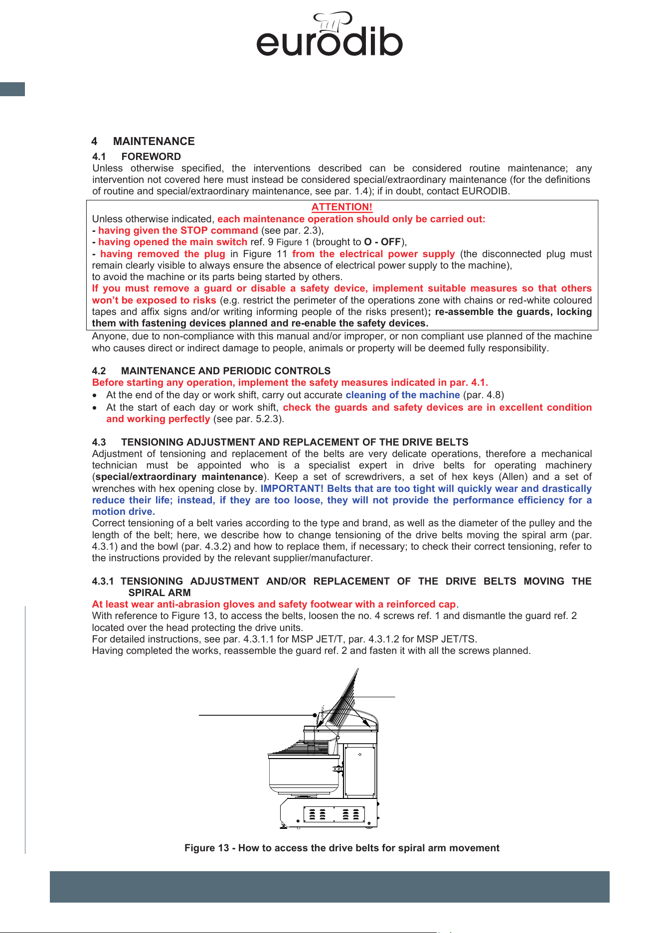
MADE IN ITALY
20
EN
spiral mixer xed bowl
UNIMIX and SUPREME Spiral Mixers Use and maintenance instructions (translation of original instructions) - Ed. 01/2019
EFFEDUE S.R.L. Via dell’Artigianato, 10 36034 MALO (VI) - I
28
7. With the cycle concluded, lift the guard and remove the dough (see par. 3.4.1, point 11); with the specific
hold-down command device (see par. 2.3) to facilitate the operation, you can rotate the bowl, if necessary
with pulsed action, to bring the dough to the best position for the operator; remember that if the relevant
command device is not held active (e.g. if the button is released), the bowl stops.
8. If you want to stop the cycle in progress, activate the command device for normal STOP (press the relevant
button or click the specific field for the“TOUCH SCREEN F2” PANEL); the machine stops, the remaining time is
saved. To restart the cycle from where it stopped, reset (if necessary) theSTOP button, then start at the speed
which was running at time of stoppage; the mixing cycle will restart where it shut off. Once the normal STOP
command is given, wait for the tool (spiral arm)to stop completely before lifting the guard. In normal
conditions, do not stop the machine by lifting the guard.
9. When you have finished using the machine, always open the main switch ref. 9 Figure 1, turning it OFF - O
and locking it with a lock and key in that position; in the event of prolonged stoppage, accurately clean the
machine (par. 4.8).
3.5 FORMATION AND TRAINING FOR OPERATORS ON MACHINE USE
As already mentioned in this manual, the employer must provide operators with adequate information and
training, even practical (training), on correct and safe use of the machine (it must be simple and understandable
based on the expected know-how that one can reasonably expect of the relevant people).
The follow prospectus provides a minimum list of topics to base the information, formation and training of staff
on; for further clarification, the following definitions are provided:
information: transfer of news, know-how, etc. without testing learning
formation: transfer of news, know-how, etc. on articulated and specific topics, testing actual
understanding of the topics covered, but without practical demonstration
training: transfer of news, know-how, etc. with practical demonstration of their application in articulated and
specific topics, and with testing of understanding through application in practical cases of the
topics covered
Topic
Information
Formation
Training
Chapters/Paragr
aphs
Use limitations and intended use of
the machine. Permitted use and
misuse
X
2.1
Machine movement
X
X
3.2
Use of commands.
X
X
X
2.3 - 3.4
How to load the ingredients
X
3.4.1
Possible anomalies and their
solutions
X
4.9
Maintenance and cleaning
operations
X
X
X
4
Use of PPE
X
X
3.4.1 - 4
Hazards and risks characterising the
machine - Residual risks
X
3.4.1
5.2.1 - 5.2.4
5.2.5 - 5.2.6
Safety devices supplied and control
of their efficiency
X
5.2.2 - 5.2.3
Noise emitted by the machine
X
5.2.6
Safety signs
X
X
5.3
Dismantling and disposal
X
6
29
4 MAINTENANCE
4.1 FOREWORD
Unless otherwise specified, the interventions described can be considered routine maintenance; any
intervention not covered here must instead be considered special/extraordinary maintenance (for the definitions
of routine and special/extraordinary maintenance, see par. 1.4); if in doubt, contact EURODIB.
ATTENTION!
Unless otherwise indicated, each maintenance operation should only be carried out:
- having given the STOP command (see par. 2.3),
- having opened the main switch ref. 9 Figure 1 (brought to O - OFF),
- having removed the plug in Figure 11 from the electrical power supply (the disconnected plug must
remain clearly visible to always ensure the absence of electrical power supply to the machine),
to avoid the machine or its parts being started by others.
If you must remove a guard or disable a safety device, implement suitable measures so that others
won’t be exposed to risks (e.g. restrict the perimeter of the operations zone with chains or red-white coloured
tapes and affix signs and/or writing informing people of the risks present); re-assemble the guards, locking
them with fastening devices planned and re-enable the safety devices.
Anyone, due to non-compliance with this manual and/or improper, or non compliant use planned of the machine
who causes direct or indirect damage to people, animals or property will be deemed fully responsibility.
4.2 MAINTENANCE AND PERIODIC CONTROLS
Before starting any operation, implement the safety measures indicated in par. 4.1.
• At the end of the day or work shift, carry out accurate cleaning of the machine (par. 4.8
)
• At the start of each day or work shift, check the guards and safety devices are in excellent condition
and working perfectly (see par. 5.2.3)
.
4.3
TENSIONING ADJUSTMENT AND REPLACEMENT OF THE DRIVE BELTS
Adjustment of tensioning and replacement of the belts are very delicate operations, therefore a mechanical
technician must be appointed who is a specialist expert in drive belts for operating machinery
(special/extraordinary maintenance). Keep a set of screwdrivers, a set of hex keys (Allen) and a set of
wrenches with hex opening close by. IMPORTANT! Belts that are too tight will quickly wear and drastically
reduce their life; instead, if they are too loose, they will not provide the performance efficiency for a
motion drive.
Correct tensioning of a belt varies according to the type and brand, as well as the diameter of the pulley and the
length of the belt; here, we describe how to change tensioning of the drive belts moving the spiral arm (par.
4.3.1) and the bowl (par. 4.3.2) and how to replace them, if necessary; to check their correct tensioning, refer to
the instructions provided by the relevant supplier/manufacturer.
4.3.1 TENSIONING ADJUSTMENT AND/OR REPLACEMENT OF THE DRIVE BELTS MOVING THE
SPIRAL ARM
At least wear anti-abrasion gloves and safety footwear with a reinforced cap.
With reference to Figure 13, to access the belts, loosen the no. 4 screws ref. 1 and dismantle the guard ref. 2
located over the head protecting the drive units.
For detailed instructions, see par. 4.3.1.1 for MSP JET/T, par. 4.3.1.2 for MSP JET/TS.
Having completed the works, reassemble the guard ref. 2 and fasten it with all the screws planned.
Figure 13 - How to access the drive belts for spiral arm movement
2
1
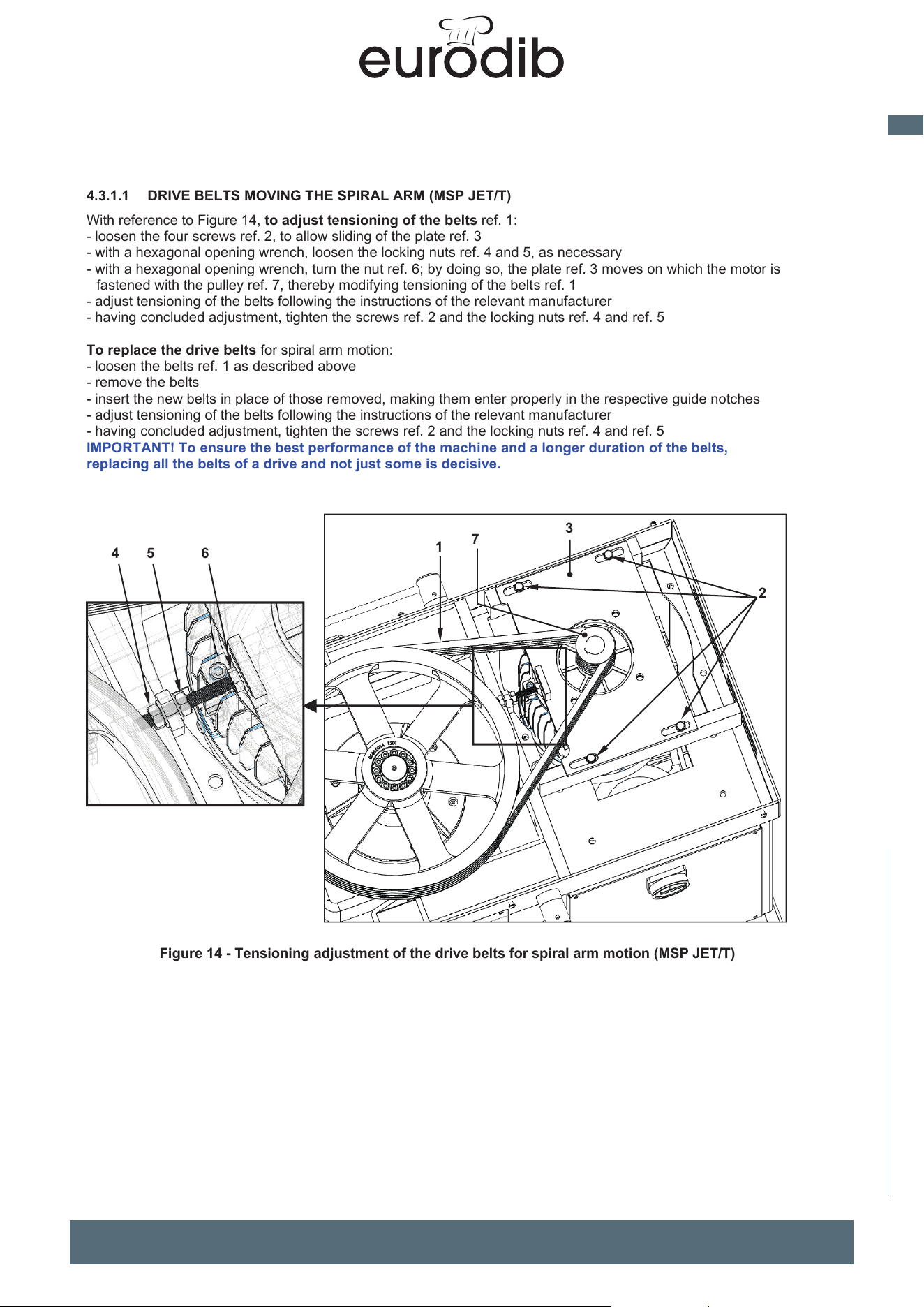
MADE IN ITALY
21
EN
spiral mixer xed bowl
30
4.3.1.1 DRIVE BELTS MOVING THE SPIRAL ARM (MSP JET/T)
With reference to Figure 14, to adjust tensioning of the belts ref. 1:
- loosen the four screws ref. 2, to allow sliding of the plate ref.
3
-
with a hexagonal opening wrench, loosen the locking nuts ref. 4 and 5, as necessary
- with a hexagonal opening wrench, turn the nut ref. 6; by doing so, the plate ref. 3 moves on which the motor is
fastened with the pulley ref. 7, thereby modifying tensioning of the belts ref. 1
- adjust tensioning of the belts following the instructions of the relevant manufacturer
- having concluded adjustment, tighten the screws ref. 2 and the locking nuts ref. 4 and ref. 5
To replace the drive belts for spiral arm motion:
- loosen the belts ref. 1 as described abov
e
- remove the belts
- insert the new belts in place of those removed, making them enter properly in the respective guide notches
- adjust tensioning of the belts following the instructions of the relevant manufacturer
- having concluded adjustment, tighten the screws ref. 2 and the locking nuts ref. 4 and ref. 5
IMPORTANT! To ensure the best performance of the machine and a longer duration of th
e belts,
r
eplacing all the belts of a drive and not just some is decisive.
Figure 14 - Tensioning adjustment of the drive belts for spiral arm motion (MSP JET/T)
1
3
4
7
2
5
6
UNIMIX and SUPREME Spiral Mixers Use and maintenance instructions (translation of original instructions) - Ed. 01/2019
EFFEDUE S.R.L. Via dell’Artigianato, 10 36034 MALO (VI) - I
31
4.3.1.2 DRIVE BELTS MOVING THE SPIRAL ARM (UNIMIX)
With reference to Figure 15
to adjust tensioning of the belts ref. 1:
- loosen the four screws ref. 2, to allow sliding of the plate ref. 3
- with a hexagonal opening wrench, turn the screw ref. 4; by doing so, the plate ref. 3 moves supporting the
motor with the pulley ref. 5, thereby modifying tensioning of the belts ref. 1
- adjust tensioning of the belts following the instructions of the relevant manufacturer
- having concluded adjustment, tighten the screws ref. 2
to adjust tensioning of the belts ref. 6:
- loosen the four screws ref. 7, to allow sliding of the plate ref. 8
- with a hexagonal opening wrench, turn the screw ref. 9; by doing so, the plate ref. 8 moves supporting the
pulley ref. 10, thereby modifying tensioning of the belts ref. 6;
- adjust tensioning of the belts following the instructions of the relevant manufacturer
- having concluded adjustment, tighten the screws ref. 7
IMPORTANT! If tensioning of the belts ref. 6 is adjusted, it may be necessary to reset tensioning also on
belts ref. 1 and vice versa. Always check correct tensioning of both.
to replace the belts:
- loosen the belts as described above
- dismantle the plate ref. 11 (simply remove the two screws ref. 12)
- remove the belts (to remove the belts ref. 1, it is however necessary to firstly remove the belts ref. 6)
- insert the new belts, making them enter properly in the respective guide notches of the respective pulleys
- assemble the plate ref. 11 and fasten it with the two screws ref. 12
- adjust tensioning of the belts following the instructions of the relevant manufacturer
- having concluded adjustment, tighten the four screws ref. 7 and, if necessary, the four screws ref. 2
IMPORTANT! To ensure the best performance of the machine and a longer duration of the belts,
replacing all the belts of a drive and not just some is decisive.
Furthermore, always check the correct tensioning of the belts ref. 1 and belts ref. 6.
Figure 15 - Tensioning adjustment of the drive belts for spiral arm motion (SUPREME)
8
6
10
3
2
1
4
5
7
9
11
12
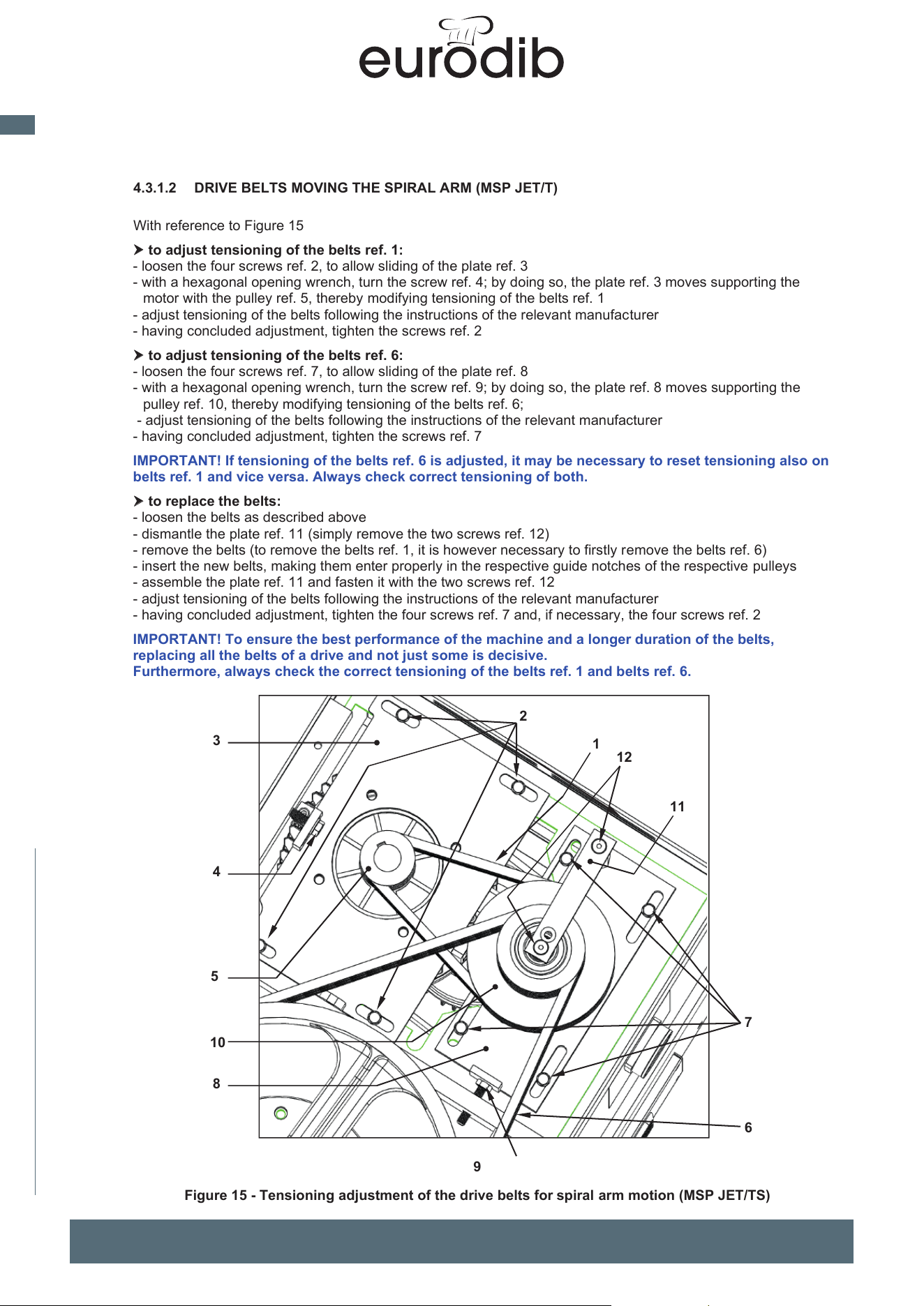
MADE IN ITALY
22
EN
spiral mixer xed bowl
UNIMIX and SUPREME Spiral Mixers Use and maintenance instructions (translation of original instructions) - Ed. 01/2019
EFFEDUE S.R.L. Via dell’Artigianato, 10 36034 MALO (VI) - I
30
4.3.1.1 DRIVE BELTS MOVING THE SPIRAL ARM (UNIMIX)
With reference to Figure 14, to adjust tensioning of the belts ref. 1:
- loosen the four screws ref. 2, to allow sliding of the plate ref. 3
- with a hexagonal opening wrench, loosen the locking nuts ref. 4 and 5, as necessary
- with a hexagonal opening wrench, turn the nut ref. 6; by doing so, the plate ref. 3 moves on which the motor is
fastened with the pulley ref. 7, thereby modifying tensioning of the belts ref. 1
- adjust tensioning of the belts following the instructions of the relevant manufacturer
- having concluded adjustment, tighten the screws ref. 2 and the locking nuts ref. 4 and ref. 5
To replace the drive belts for spiral arm motion:
- loosen the belts ref. 1 as described above
- remove the belts
- insert the new belts in place of those removed, making them enter properly in the respective guide notches
- adjust tensioning of the belts following the instructions of the relevant manufacturer
- having concluded adjustment, tighten the screws ref. 2 and the locking nuts ref. 4 and ref. 5
IMPORTANT! To ensure the best performance of the machine and a longer duration of the belts,
replacing all the belts of a drive and not just some is decisive.
Figure 14 - Tensioning adjustment of the drive belts for spiral arm motion (UNIMIX)
1
3
4
7
2
5
6
31
4.3.1.2 DRIVE BELTS MOVING THE SPIRAL ARM (
MSP JET/T
)
With reference to Figure 15
to adjust tensioning of the belts ref. 1:
- loosen the four screws ref. 2, to allow sliding of the plate ref.
3
- with a hexagonal opening wrench, turn the screw ref. 4; by doing so, the plate ref. 3 moves supporting the
motor with the pulley ref. 5, thereby modifying tensioning of the belts ref. 1
- adjust tensioning of the belts following the instructions of the relevant manufacturer
- having concluded adjustment, tighten the screws ref. 2
to adjust tensioning of the belts ref. 6:
- loosen the four screws ref. 7, to allow sliding of the plate ref.
8
- with a hexagonal opening wrench, turn the screw ref. 9; by doing so, the plate ref. 8 moves supporting the
pulley ref. 10, thereby modifying tensioning of the belts ref. 6;
- adjust tensioning of the belts following the instructions of the relevant manufacturer
- having concluded adjustment, tighten the screws ref. 7
IMPORTANT! If tensioning of the belts ref. 6 is adjusted, it may be necessary to reset tensioning also on
belts ref. 1 and vice versa. Always check correct tensioning of both.
to replace the belts:
- loosen the belts as described abov
e
-
dismantle the plate ref. 11 (simply remove the two screws ref. 12)
- remove the belts (to remove the belts ref. 1, it is however necessary to firstly remove the belts ref. 6)
- insert the new belts, making them enter properly in the respective guide notches of the respective pulleys
- assemble the plate ref. 11 and fasten it with the two screws ref. 12
- adjust tensioning of the belts following the instructions of the relevant manufacturer
- having concluded adjustment, tighten the four screws ref. 7 and, if necessary, the four screws ref. 2
IMPORTANT! To ensure the best performance of the machine and a longer duration of the belts,
replacing all the belts of a drive and not just some is decisive.
Furthermore, always check the correct tensioning of the belts ref. 1 and belts ref. 6.
8
10
3
2
1
4
5
7
6
9
Figure 15 - Tensioning adjustment of the drive belts for spiral arm motion (MSP JET/TS)
11
12
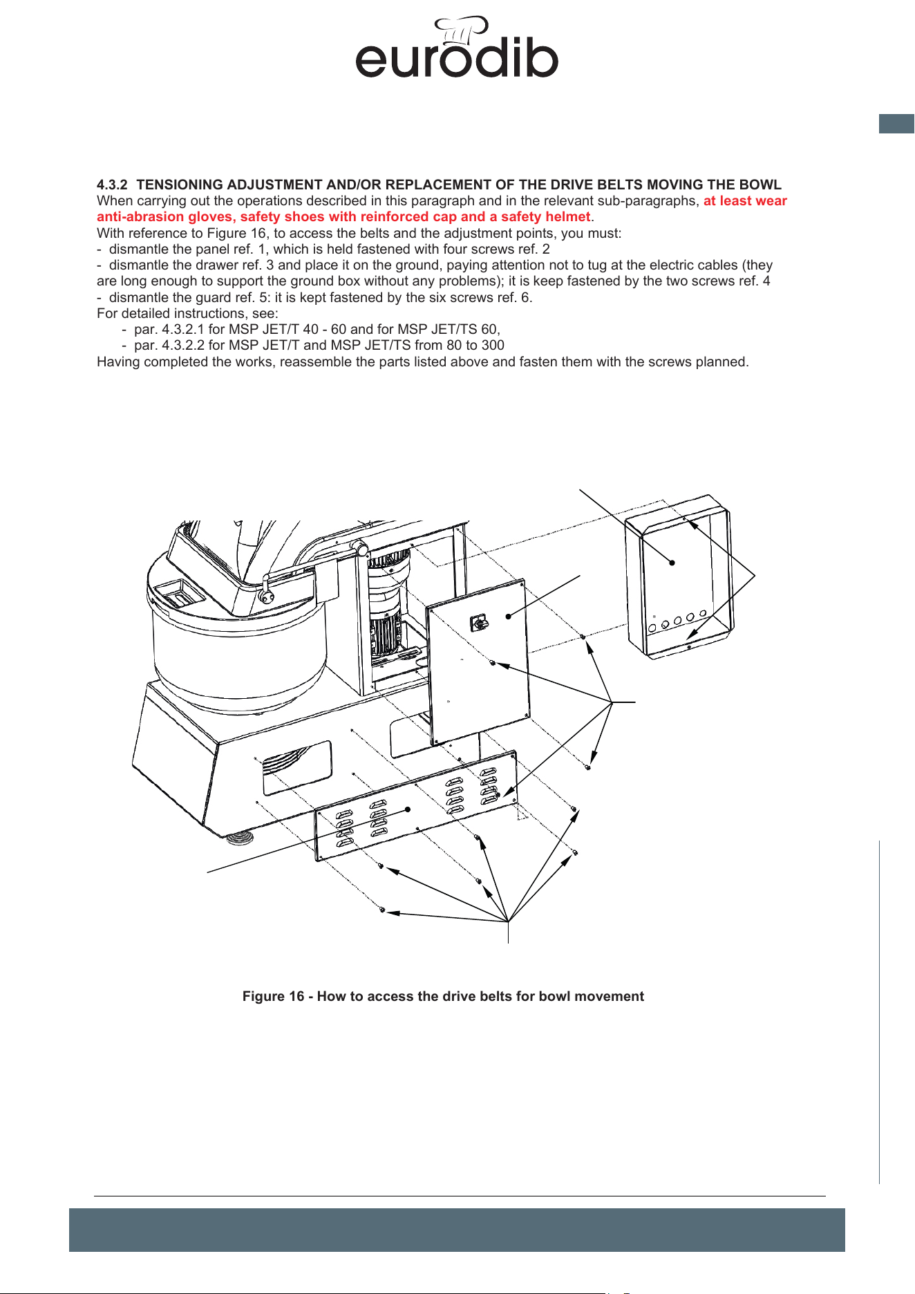
MADE IN ITALY
23
EN
spiral mixer xed bowl
32
4.3.2 TENSIONING ADJUSTMENT AND/OR REPLACEMENT OF THE DRIVE BELTS MOVING THE BOWL
When carrying out the operations described in this paragraph and in the relevant sub-paragraphs, at least wear
anti-abrasion gloves, safety shoes with reinforced cap and a safety helmet.
With reference to Figure 16, to access the belts and the adjustment points, you must:
- dismantle the panel ref. 1, which is held fastened with four screws ref. 2
-
dismantle the drawer ref. 3 and place
it on the ground, paying attention not to tug at the electric cables
(they
are long
enough to support the ground box without any problems); it is keep fastened by the two screws ref. 4
- dismantle the guard ref. 5: it is kept fastened by
the six screws ref. 6.
For detailed instructions, see:
- par.
4.3.2.1 for MSP JET/T 40 - 60 and for MSP JET/TS 60,
- par.
4.3.2.2 for MSP JET/T and MSP JET/TS from 80 to 300
Having completed the works, reassemble the parts listed above and fasten them with the screws planned.
Figure 16 - How to access the drive belts for bowl movement
UNIMIX and SUPREME Spiral Mixers Use and maintenance instructions (translation of original instructions) - Ed. 01/2019
EFFEDUE S.R.L. Via dell’Artigianato, 10 36034 MALO (VI) - I
33
4.3.2.1 DRIVE BELTS MOVING THE BOWL UNIMIX M40 - M60 AND SUPREME M60
With reference to Figure 17
:
to adjust tensioning of the belts ref. 1:
- loosen the four screws ref. 2, to allow sliding of the plate ref. 3
- with a hexagonal opening wrench, turn the blind nut ref. 4; by doing so, the plate ref. 3 moves on which the
motor ref. 10 is fastened with the pulley ref. 5, thereby modifying tensioning of the belts ref. 1
- adjust tensioning of the belts following the instructions of the relevant manufacturer
- having concluded adjustment, tighten the screws ref. 2
to adjust tensioning of the belts ref. 6:
- with a hexagonal opening wrench, turn the blind nut ref. 7; by doing so, the arm moves supporting the pulley
ref. 8 and ref. 9, thereby modifying tensioning of the belts ref. 6 (but also the belts ref. 1);
- adjust tensioning of the belts following the instructions of the relevant manufacturer
IMPORTANT! If tensioning of the belts ref. 1 is adjusted, it may be necessary to reset tensioning also on
belts ref. 6 and vice versa. Always check correct tensioning of both.
to replace the belts:
- loosen the belts as described above, enough to make them exit the notches of the respective pulleys, then
remove them and extract them
- insert the new belts, making them enter properly in the respective guide notches of the respective pulleys
- adjust tensioning of the belts following the instructions of the relevant manufacturer
- having concluded adjustment, tighten the four screws ref. 2
IMPORTANT! To ensure the best performance of the machine and a longer duration of the belts,
replacing all the belts of a drive and not just some is decisive.
Furthermore, always check the correct tensioning of the belts ref. 1 and belts ref. 6.
Figure 17 - Correct tensioning of the drive belts moving the bowl (M40 and M60)
2
3
4
8
5
1
6
9
7
10
6
1
2
3
4
5
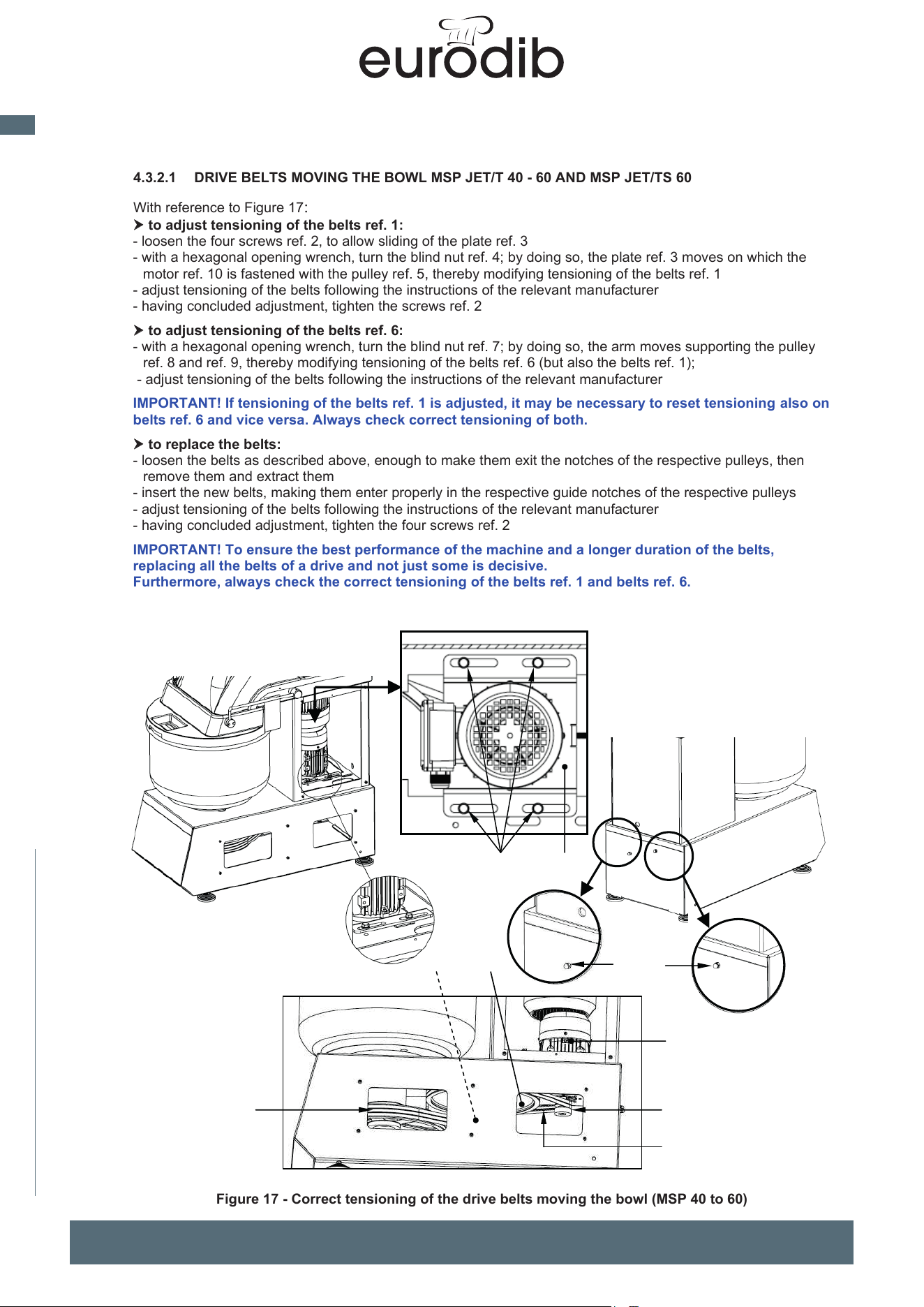
MADE IN ITALY
24
EN
spiral mixer xed bowl
UNIMIX and SUPREME Spiral Mixers Use and maintenance instructions (translation of original instructions) - Ed. 01/2019
EFFEDUE S.R.L. Via dell’Artigianato, 10 36034 MALO (VI) - I
32
4.3.2 TENSIONING ADJUSTMENT AND/OR REPLACEMENT OF THE DRIVE BELTS MOVING THE BOWL
When carrying out the operations described in this paragraph and in the relevant sub-paragraphs, at least wear
anti-abrasion gloves, safety shoes with reinforced cap and a safety helmet.
With reference to Figure 16, to access the belts and the adjustment points, you must:
- dismantle the panel ref. 1, which is held fastened with four screws ref. 2
- dismantle the drawer ref. 3 and place it on the ground, paying attention not to tug at the electric cables (they
are long enough to support the ground box without any problems); it is keep fastened by the two screws ref. 4
- dismantle the guard ref. 5: it is kept fastened by the six screws ref. 6.
For detailed instructions, see:
- par. 4.3.2.1 for UNIMIX M40 - M60 and for SUPREME M60,
- par. 4.3.2.2 for UNIMIX and SUPREME from M80 to M300
Having completed the works, reassemble the parts listed above and fasten them with the screws planned.
Figure 16 - How to access the drive belts for bowl movement
1
2
3
4
6
5
33
4.3.2.1 DRIVE BELTS MOVING THE BOWL MSP JET/T 40 - 60 AND MSP JET/TS 60
With reference to Figure 17:
to adjust tensioning of the belts ref. 1:
- lo
osen the four screws ref. 2, to allow sliding of the plate ref.
3
-
with a hexagonal opening wrench, turn the blind nut ref. 4; by doing so, the plate ref. 3 moves on which th
e
mo
tor ref. 10 is fastened with the pulley ref. 5, thereby modifying tensioning of the belts ref. 1
- adjust tensioning of the belts following the instructions of the relevant manufacturer
- having concluded adjustment, tighten the screws ref. 2
to adjust tensioning of the belts ref. 6:
- wi
th a hexagonal opening wrench, turn the blind nut ref. 7; by doing so, the arm moves supporting the pulley
ref. 8 and ref. 9, thereby modifying tensioning of the belts ref. 6 (but also the belts ref.
1);
- adjust tensioning of the belts following the instructions of the relevant manufacturer
IMPORTANT! If tensioning of the belts ref. 1 is adjusted, it may be necessary to reset tensioning also on
belts ref. 6 and vice versa. Always check correct tensioning of both.
to replace the belts:
- loosen the belts as described above, enough to make them exit the notches of the respective pulleys, the
n
remove them and extract them
- insert the new belts, making them enter properly in the respective guide notches of the respective pulleys
- adjust tensioning of the belts following the instructions of the relevant manufacturer
- having concluded adjustment, tighten the four screws ref.
2
IMP
ORTANT! To ensure the best performance of the machine and a longer duration of the belts,
replacing all the belts of a drive and not just some is decisive.
Furthermore, always check the correct tensioning of the belts ref. 1 and belts ref. 6.
Figure 17 - Correct tensioning of the drive belts moving the bowl (MSP 40 to 60)
2
3
4
8
5
1
6
9
7
10
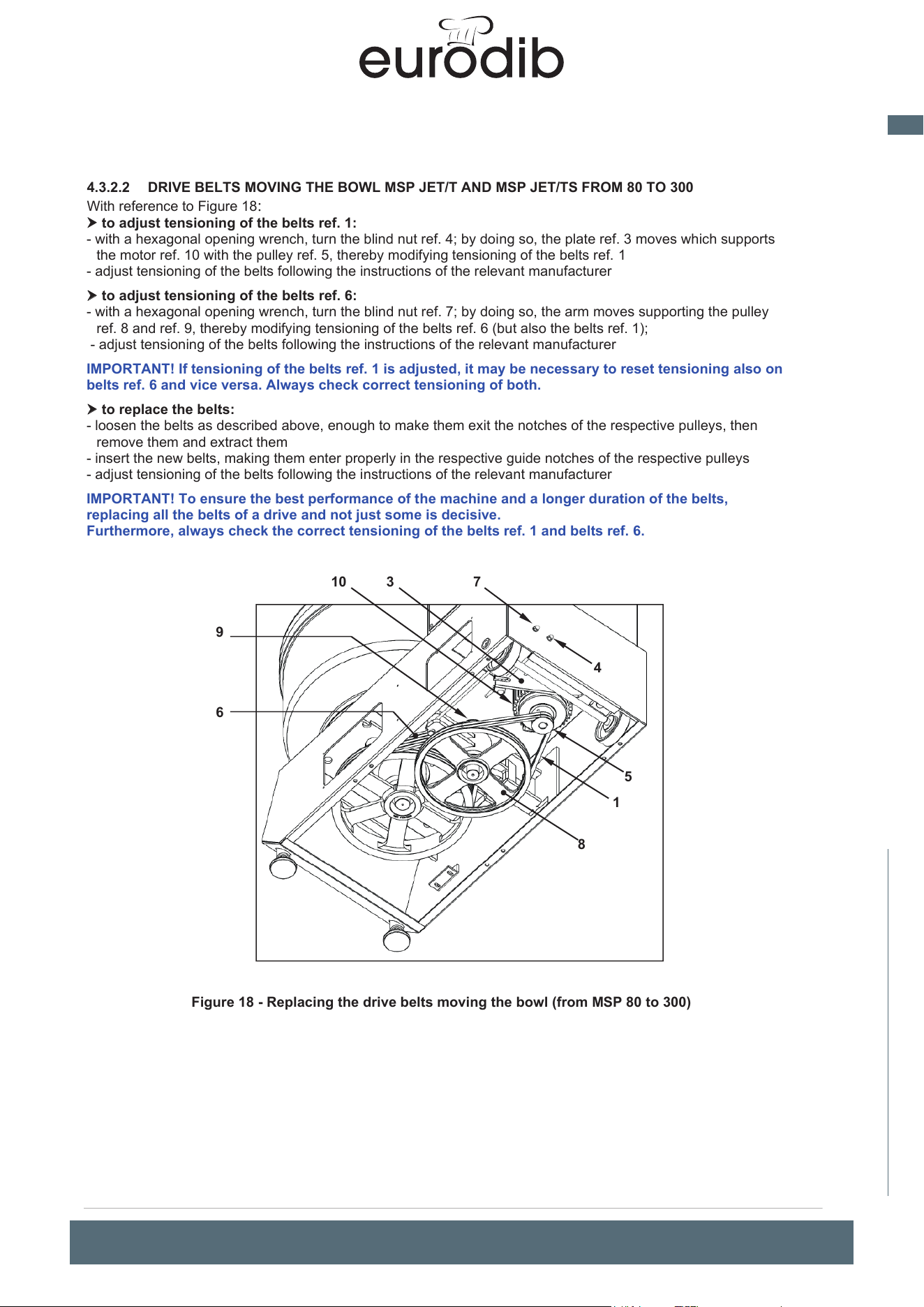
MADE IN ITALY
25
EN
spiral mixer xed bowl
34
4.3.2.2 DRIVE BELTS MOVING THE BOWL MSP JET/T
AND MSP JET/TS FROM 80 TO 300
With reference to Figure 18:
to adjust tensioning of the belts ref. 1:
- with a hexagonal opening wrench, turn the blind nut ref. 4; by doing so, the plate ref. 3 moves which supports
the motor ref. 10 with the pulley ref. 5, thereby modifying tensioning of the belts ref. 1
- adjust tensioning of the belts following the instructions of the relevant manufacturer
to adjust tensioning of the belts ref. 6:
- with a hexagonal opening wrench, turn the blind nut ref. 7; by doing so, the arm moves supporting the pulley
ref. 8 and ref. 9, thereby modifying tensioning of the belts ref. 6 (but also the belts ref.
1);
- adjust tensioning of the belts following the instructions of the relevant manufacturer
IMPORTANT! If tensioning of the belts ref. 1 is adjusted, it may be necessary to reset tensioning also on
belts ref. 6 and vice versa. Always check correct tensioning of both.
to replace the belts:
-
loosen the belts as described above, enough to make them exit the notches of the respective pulleys, the
n
r
emove them and extract them
- insert the new belts, making them enter properly in the respective guide notches of the respective pulleys
- adjust tensioning of the belts following the instructions of the relevant manufacturer
IMPORTANT! To ensure the best performance of the machine and a longer duration of the belts,
replacing all the belts of a drive and not just some is decisive.
Furthermore, always check the correct tensioning of the belts ref. 1 and belts ref. 6.
Figure 18 - Replacing the drive belts moving the bowl (from MSP 80 to 300)
1
4
7
5
10
3
6
8
9
UNIMIX and SUPREME Spiral Mixers Use and maintenance instructions (translation of original instructions) - Ed. 01/2019
EFFEDUE S.R.L. Via dell’Artigianato, 10 36034 MALO (VI) - I
35
4.4 REPLACING AND ADJUSTING THE BOWL PUSHING CASTORS AND RELEVANT SUPPORTS
With reference to Figure 19, each of the two units push the bowl pusher (one per side of the machine). It is
essentially composed of an idle roller ref. 1 and a support ref. 2; their function is to counter the force of the spiral
arm under whose thrust the bowl ref. 7 would tend to deform. When a roller is excessively worn or damaged, or
is finding rotation difficult (or doesn't rotate at all), it must be replaced; EFFEDUE will provide the unit with the
roller + support ready for assembly on the machine. To replace the roller unit + support:
- remove the screws ref. 3 and ref. 4 with the relevant washers (pay attention you don’t lose them; put them in a
safe place)
- remove the unit with the roller + support
- position the new unit in the machine, as displayed in the figure, and screw in, but don’t tighten the screws ref. 3
with the relevant washers, in the threaded holes of the column after inserting them in the slots ref. 5 of the
support ref. 2; do the same for screws ref. 4, with relevant washers, and the slots ref. 6
- since the bowl ref. 7 is not perfectly cylindrical, the roller ref. 1 must be positioned in such a way it touches the
side of the bowl in the point where it is nearest to the roller; to do this, move the unit by taking advantage of
the slots ref. 5 and ref. 6;
- once the right position is found, fasten everything by tightening the screws ref. 3 and ref. 4
- check the distance between the support ref. 2 and the bowl and between the disc ref. 8 is not over 4 mm, this
is very important to minimise the risk of catching, dragging, crushing between the roller ref. 1 and the side of
the bowl ref. 7; if you cannot respect the aforementioned maximum distance, do not use the machine and
immediately contact EFFEDUE.
Figure 19 - Bowl pushing castors
4.5 ELECTRICAL MAINTENANCE
Considering the high risk and the seriousness of the damage in the event of an accident, every operation even
if simple (e.g. replacing a fuse) that directly or indirectly involves the electrical equipment on the machine, must
only be carried out by specialist and expressly appointed technicians (special/extraordinary
maintenance) with technical and legislative know-how to carry out the works to standard and safely. They must
firstly read and clearly understand the content of this manual.
The same applies to replacement of the timer (see par. 4.6) and the micro-switch associated with the
guard placed over the bowl, the latter operation also requires mechanical capacity and know-how for
controls and any adjustments to carry out.
ATTENTION!
Having sectioned and reset the electrical power supply to zero by opening the main switch, electrical
voltage remains present in the connection terminals of the electrical power conductors, in other cables
working off them and parts powered by them.
ATTENTION! (Only for machines equipped with an inverter)
Having sectioned and reset the electrical power supply to zero, residual electrical voltage remains in the
inverter which could be very dangerous for personal safety if contact is made with the relevant parts
with this voltage; par. 5.2.5 provides further details on the topic and information on precautions to take
to avoid exposure to electricity-related risks.
2
1
3
3
4
5
5
6
7
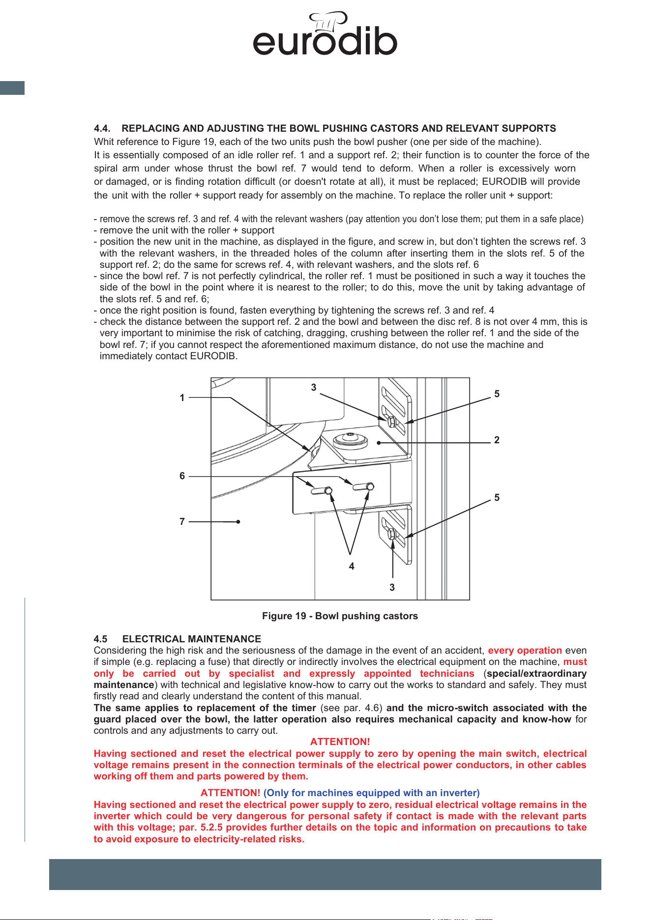
MADE IN ITALY
26
EN
spiral mixer xed bowl
UNIMIX and SUPREME Spiral Mixers Use and maintenance instructions (translation of original instructions) - Ed. 01/2019
EFFEDUE S.R.L. Via dell’Artigianato, 10 36034 MALO (VI) - I
34
4.3.2.2 DRIVE BELTS MOVING THE BOWL UNIMIX AND SUPREME FROM M80 TO M300
With reference to Figure 18:
to adjust tensioning of the belts ref. 1:
- with a hexagonal opening wrench, turn the blind nut ref. 4; by doing so, the plate ref. 3 moves which supports
the motor ref. 10 with the pulley ref. 5, thereby modifying tensioning of the belts ref. 1
- adjust tensioning of the belts following the instructions of the relevant manufacturer
to adjust tensioning of the belts ref. 6:
- with a hexagonal opening wrench, turn the blind nut ref. 7; by doing so, the arm moves supporting the pulley
ref. 8 and ref. 9, thereby modifying tensioning of the belts ref. 6 (but also the belts ref. 1);
- adjust tensioning of the belts following the instructions of the relevant manufacturer
IMPORTANT! If tensioning of the belts ref. 1 is adjusted, it may be necessary to reset tensioning also on
belts ref. 6 and vice versa. Always check correct tensioning of both.
to replace the belts:
- loosen the belts as described above, enough to make them exit the notches of the respective pulleys, then
remove them and extract them
- insert the new belts, making them enter properly in the respective guide notches of the respective pulleys
- adjust tensioning of the belts following the instructions of the relevant manufacturer
IMPORTANT! To ensure the best performance of the machine and a longer duration of the belts,
replacing all the belts of a drive and not just some is decisive.
Furthermore, always check the correct tensioning of the belts ref. 1 and belts ref. 6.
Figure 18 - Replacing the drive belts moving the bowl (from M80 to M300)
1
4
7
5
10
3
6
8
9
35
4.4. REPLACING AND ADJUSTING THE BOWL PUSHING CASTORS AND RELEVANT SUPPORTS
Whit reference to Figure 19, each of the two units push the bowl pusher (one per side of the machine).
It is essentially composed of an idle roller ref. 1 and a support ref. 2; their function is
to counter the force of the
spiral arm under whose thrust the bowl ref. 7 would tend to deform. When a roller is excessively worn
or damaged, or is finding rotation difficult (or doesn't rotate at all), it must be replaced; EURODIB will provide
the unit with the roller + support ready for assembly on the machine. To replace the roller unit + support:
-
remove the screws ref. 3 and ref. 4 with the relevant washers (pay attention you don’t lose them; put them in a safe place)
- remove the unit with the roller + support
- position the new unit in the machine, as displayed in the figure, and screw in, but don’t tighten the screws ref. 3
with the relevant washers, in the threaded holes of the column after inserting them in the slots ref. 5 of the
support ref. 2; do the same for screws ref. 4, with relevant washers, and the slots ref. 6
- since the bowl ref. 7 is not perfectly cylindrical, the roller ref. 1 must be positioned in such a way it touches the
side of the bowl in the point where it is nearest to the roller; to do this, move the unit by taking advantage of
the slots ref. 5 and ref. 6;
- once the right position is
found, fasten everything by tightening the screws ref. 3 and ref. 4
- check the distance between the support ref. 2 and the bowl and between the disc ref. 8 is not over 4 mm, this is
very important to minimise the risk of catching, dragging, crushing between the roller ref. 1 and the side of the
bowl ref. 7; if you cannot respect the aforementioned maximum distance, do not use the machine and
immediately contact EURODIB.
Figure 19 - Bowl pushing castors
4.5 ELECTRICAL MAINTENANCE
Considering the high risk and the seriousness of the damage in the event of an accident, every operation even
if simple (e.g. replacing a fuse) that directly or indirectly involves the electrical equipment on the machine, must
only be carried out by specialist and expressly appointed technicians (special/extraordinary
maintenance) with technical and legislative know-how to carry out the works to standard and safely. They must
firstly read and clearly understand the content of this manual.
The same applies to replacement of the timer (see par. 4.6) and the micro-switch associated with the
guard placed over the bowl, the latter operation also requires mechanical capacity and know-how for
controls and any adjustments to carry out.
ATTENTION!
Having sectioned and reset the electrical power supply to zero by opening the main switch, electrical
voltage remains present in the connection terminals of the electrical power conductors, in other cables
working off them and parts powered by them.
ATTENTION! (Only for machines equipped with an inverter)
Having sectioned and reset the electrical power supply to zero, residual electrical voltage remains in the
inverter which could be very dangerous for personal safety if contact is made with the relevant parts
with this voltage; par. 5.2.5 provides further details on the topic and information on precautions to take
to avoid exposure to electricity-related risks.
2
1
3
3
4
5
5
6
7
MADE IN ITALY
27
EN
spiral mixer xed bowl
36
4.6 REPLACEMENT OF ELECTROMECHANICAL TIMERS
To ensure sufficient reliability of machine stoppage on opening the guard under the maximum permitted
time (see par. 5.2.2 and 5.2.3), the timers ref. 2 and ref. 4 Figure 2 and Figure 3 and must be replaced at
least:
- every 7.5 years for an assumed 50 cycles/day for 365 days/year,
- every 9 years for an assumed 50 cycles/day for 300 days/year
Replacement must be entrusted to an expert technician of electrical systems on the machine
(special/extraordinary maintenance) and should be carried out in strict compliance with the wiring
diagram attached.
4.7 REPLACEMENT OF THE SAFETY MICRO-SWITCH/ES ASSOCIATED WITH THE BOWL GUARD
The following safety devices are associated with the interlocked guard ref. 5 Figure 1 placed over the bowl:
- no. 2 micro-switches, for machines with an electro-mechanical control panel (see par. 2.3.1 and 2.3.2)
- no. 1 micro-switch, for machines with a touch screen control panel (see par. 2.3.3 and 2.3.4)
With reference to Figure 20, where replacement is necessary of the/a micro-switch, proceed as follows (for
machines equipped with no. 2 micro-switches in Figure 20 only one is shown with ref. 1, the other, ref. 7, only
has the position indicated, but the replacement instructions are the same for both):
- dismantle the guard placed over the protective head of the drive units and held in place with no. 4 screws, as
explained in detail in par. 4.3.1 and shown in Figure 13
- dismantle the drive belts (see par. 4.3.1.1 for MSP JET/T, par. 4.3.1.2 for MSP JET/TS)
- to access the micro-switch ref. 1, you must dismantle the pulley ref. 2; to do so, remove the no. 6 socket head
screws ref. 3 fastening the shrink disc ref. 4, fully screw in 3 in the threaded holes ref. 5; use a hex key (Allen) to
screw in a little at a time alternatively; they will act as extractors; once the shrink disc ref. 4 is free, you can
remove the pulley + shrink disc unit
- unscrew the socket head screws (Allen) ref. 6 fastening the micro-switch ref. 7
- with a screwdriver, remove the screw ref. 8, then remove the lid of the contacts ref. 9
- loosen the screws ref. 10 of the terminals, unscrew the cable gland ref. 11, remove the cable ref. 12 from the
micro-switch
- insert the cables ref. 12 in the new micro-switch and connect them to the terminals, fastening the screws ref.
10
- screw in the cable gland ref. 11, assemble the lid ref. 9 and fasten with the screw ref. 8
- spread some medium threadlock product (e.g. LOCTITE243, medium hold, or equivalent) on the stems of the
screws ref. 6 and, keeping the through-holes aligned ref. 13 of the micro-switch with the corresponding threaded
holes of the frame of the support ref. 14, insert the screw ref. 6 and screw them in to fasten the micro-switch ref.
7; the physical characteristics and the performance of the new micro-switch must be equal or better than that
replaced (same measurements and centre distance between the fastening holes, stable closure of the contacts
with guard lowered, etc.): with the guard lowered, the head ref. 15 of the micro-switch must enter the cavity ref.
16 of the cam ref. 17 and result as being not pressed
- check the micro-switch intervenes (you will hear a gentle click) when the distance between the edge of the
bowl and the guard is less than 75 mm (also see par. 5.2.2); if this is not the case, loosen the screws ref. 6 and
move the micro-switch (the holes for the screws ref. 2 allow slight adjustments) to meet this condition.
- screw in and tighten the cable gland ref. 11 on the bottom of the micro-switch
- assemble the pulley ref. 2 with the shrink disc ref. 4, having removed from the latter the three screws used as
extractors; do so to ensure the central hole of the shrink disc ref. 4 is inserted on the shaft ref. 18, lower the
pulley until it reaches the mechanical stop
- with a hex key (Allen), screw in the no. 6 screws ref. 3 a little at a time and alternatively, until they are fully
tightened
- assemble the belts and adjust their tensioning (see par. 4.3.1.1 for MSP JET/T, par. 4.3.1.2 for MSP JET/TS)
- reassemble the guard ref. 2 and fasten it with all the screws planned.
IMPORTANT!
The position of the micro-switch is adjusted on the new machine in EURODIB before delivery; once
adjustment is complete, the position of the support frame ref. 14 is secured with a film of medium
threadlock (e.g. green LOCTITE, medium hold or equivalent) on the stem of the screw ref. 19 and with a
steel pin ø 3 mm forced into the hole ref. 20 and into the corresponding hole on the structure of the
machine.
ATTENTION!
It is forbidden to remove the screw ref. 19 (or even just loosen it) and/or remove the pin ø 3 mm described
above. If, for any reason, you need to remove the screw ref. 19 and/or the aforementioned pin, it is
compulsory after checking as described that the frame ref. 14 is fastened in its definitive position. Spread a
film of medium threadlock on the stem of the screw ref. 19 and make a new hole on the frame and in the
structure of the machine, so they are mutually aligned and of equal diameter to insert a cylindrical pin of
adequate length and diameter for the diameter and depth of the hole.
UNIMIX and SUPREME Spiral Mixers Use and maintenance instructions (translation of original instructions) - Ed. 01/2019
EFFEDUE S.R.L. Via dell’Artigianato, 10 36034 MALO (VI) - I
37
Figure 20 - Replacement of the micro-switch associated with the guard
1
3
5
4
5
5
1
7
6
6
8
9
10
11
12
13
15
16
17
19
2
18
14
20
7
MADE IN ITALY
28
EN
spiral mixer xed bowl
UNIMIX and SUPREME Spiral Mixers Use and maintenance instructions (translation of original instructions) - Ed. 01/2019
EFFEDUE S.R.L. Via dell’Artigianato, 10 36034 MALO (VI) - I
36
4.6 REPLACEMENT OF ELECTROMECHANICAL TIMERS
To ensure sufficient reliability of machine stoppage on opening the guard under the maximum permitted
time (see par. 5.2.2 and 5.2.3), the timers ref. 2 and ref. 4 Figure 2 and Figure 3 and must be replaced at
least:
- every 7.5 years for an assumed 50 cycles/day for 365 days/year,
- every 9 years for an assumed 50 cycles/day for 300 days/year
Replacement must be entrusted to an expert technician of electrical systems on the machine
(special/extraordinary maintenance) and should be carried out in strict compliance with the wiring
diagram attached.
4.7 REPLACEMENT OF THE SAFETY MICRO-SWITCH/ES ASSOCIATED WITH THE BOWL GUARD
The following safety devices are associated with the interlocked guard ref. 5 Figure 1 placed over the bowl:
- no. 2 micro-switches, for machines with an electro-mechanical control panel (see par. 2.3.1 and 2.3.2)
- no. 1 micro-switch, for machines with a touch screen control panel (see par. 2.3.3 and 2.3.4)
With reference to Figure 20, where replacement is necessary of the/a micro-switch, proceed as follows (for
machines equipped with no. 2 micro-switches in Figure 20 only one is shown with ref. 1, the other, ref. 7, only
has the position indicated, but the replacement instructions are the same for both):
- dismantle the guard placed over the protective head of the drive units and held in place with no. 4 screws, as
explained in detail in par. 4.3.1 and shown in Figure 13
- dismantle the drive belts (see par. 4.3.1.1 for UNIMIX, par. 4.3.1.2 for SUPREME)
- to access the micro-switch ref. 1, you must dismantle the pulley ref. 2; to do so, remove the no. 6 socket head
screws ref. 3 fastening the shrink disc ref. 4, fully screw in 3 in the threaded holes ref. 5; use a hex key (Allen)
to screw in a little at a time alternatively; they will act as extractors; once the shrink disc ref. 4 is free, you can
remove the pulley + shrink disc unit
- unscrew the socket head screws (Allen) ref. 6 fastening the micro-switch ref. 7
- with a screwdriver, remove the screw ref. 8, then remove the lid of the contacts ref. 9
- loosen the screws ref. 10 of the terminals, unscrew the cable gland ref. 11, remove the cable ref. 12 from the
micro-switch
- insert the cables ref. 12 in the new micro-switch and connect them to the terminals, fastening the screws ref.
10
- screw in the cable gland ref. 11, assemble the lid ref. 9 and fasten with the screw ref. 8
- spread some medium threadlock product (e.g. LOCTITE243, medium hold, or equivalent) on the stems of the
screws ref. 6 and, keeping the through-holes aligned ref. 13 of the micro-switch with the corresponding
threaded holes of the frame of the support ref. 14, insert the screw ref. 6 and screw them in to fasten the
micro-switch ref. 7; the physical characteristics and the performance of the new micro-switch must be equal or
better than that replaced (same measurements and centre distance between the fastening holes, stable
closure of the contacts with guard lowered, etc.): with the guard lowered, the head ref. 15 of the micro-switch
must enter the cavity ref. 16 of the cam ref. 17 and result as being not pressed
- check the micro-switch intervenes (you will hear a gentle click) when the distance between the edge of the
bowl and the guard is less than 75 mm (also see par. 5.2.2); if this is not the case, loosen the screws ref. 6
and move the micro-switch (the holes for the screws ref. 2 allow slight adjustments) to meet this condition.
- screw in and tighten the cable gland ref. 11 on the bottom of the micro-switch
- assemble the pulley ref. 2 with the shrink disc ref. 4, having removed from the latter the three screws used as
extractors; do so to ensure the central hole of the shrink disc ref. 4 is inserted on the shaft ref. 18, lower the
pulley until it reaches the mechanical stop
- with a hex key (Allen), screw in the no. 6 screws ref. 3 a little at a time and alternatively, until they are fully
tightened
- assemble the belts and adjust their tensioning (see par. 4.3.1.1 for UNIMIX, par. 4.3.1.2 for SUPREME)
- reassemble the guard ref. 2 and fasten it with all the screws planned.
IMPORTANT!
The position of the micro-switch is adjusted on the new machine in EFFEDUE before delivery; once
adjustment is complete, the position of the support frame ref. 14 is secured with a film of medium
threadlock (e.g. green LOCTITE, medium hold or equivalent) on the stem of the screw ref. 19 and with a
steel pin ø 3 mm forced into the hole ref. 20 and into the corresponding hole on the structure of the
machine.
ATTENTION!
It is forbidden to remove the screw ref. 19 (or even just loosen it) and/or remove the pin ø 3 mm described
above.
If, for any reason, you need to remove the screw ref. 19 and/or the aforementioned pin, it is compulsory after
checking as described that the frame ref. 14 is fastened in its definitive position. Spread a film of medium
threadlock on the stem of the screw ref. 19 and make a new hole on the frame and in the structure of the
machine, so they are mutually aligned and of equal diameter to insert a cylindrical pin of adequate length and
diameter for the diameter and depth of the hole.
37
Figure 20 - Replacement of the micro-switch associated with the guard
1
3
5
4
5
5
1
7
6
6
8
9
10
11
12
13
15
16
17
19
2
18
14
20
7
MADE IN ITALY
29
EN
spiral mixer xed bowl
38
4.8 CLEANING
Before starting any operation, implement the safety measures described in par. 4.1
Ensure the machine is perfectly hygienic: clean it carefully at the end of each day and/or work shift. Complete
and accurate cleaning should be carried out each time machine stoppage for over twelve hours is
planned to avoid biological risks arising due to possible proliferation of mildew, bacteria, etc. Cleaning
should be carried out as follows:
- ensure nobody is around the machine
- wear a mask to protect against dust inhalation (with an adequate filtering capacity for the grain size of the
flour; see par. 3.4.1, point 4) and full protection safety goggles; ventilate the environment during and at
least 15 minutes after the operations are complete; if possible, clean outdoors.
- with a vacuum cleaner with slender opening attachment, from inside the bowl remove flour and/or dough
residue from the cover and the bowl guard; if necessary, move more stubborn residue with a plastic spatul
a
an
d/or brush with medium consistency synthetic bristles. Before using the vacuum cleaner and only if strict
ly
n
ecessary, use short blows of compressed air to move the residue from difficult to reach parts
- use a clean cloth wet with drinking water, but not dripping, to wipe each surface that comes in contact wit
h
foo
d; in particular, the inside and upper edging of the bowl, cover, bowl guard (also in the slot area for th
e
ad
dition of ingredients), central tool, spiral arm and part under the head that above the bowl.
- also with a cloth dampened with drinking water (but not dripping) wipe the other reachable surfaces of the
machine, then dry them with a clean cloth
Do not use metal objects to avoid damaging the parts. Do not use water jets/sprays.
Before using the machine again, ensure the parts are perfectly dry. If not, deposits and encrustations could form
of flour mixed with water which, over time, could be difficult to remove.
4.9 POSSIBLE FAULTS AND/OR ANOMALIES
We will now indicate possible faults and/or anomalies. The resulting intervention should be carried out in
compliance with the instructions, where existing and, in any case, only having implemented all the necessary
preventive safety measures, most importantly those in par. 4.1.
Fault and/or
anomaly
Possible causes
Solutions
The machine won’t
switch on
• No power
• Intervention of safety fuses and/or circuit
break
er switches
- Check the plug is well inserted, that the main
switch is on I (ON) and that the guards on the
el
ectricity line of the premises have n
ot
i
ntervened; if necessary, replace them.
- Replace the fuses and/or reset the circuit
breakers that intervened (extraordinary
maintenance)
The machine won’t
start
• STOP button pressed
• Bowl guard not closed
• Bowl guard micro-switch faulty
- Reset it (par. 5.2.2, point 3)
- Completely close it
- Replace it (special/extraordinary maintenance)
4.10 SPARE PARTS
The list of recommended spare parts is delivered with this manual.
To order spare parts, always contact the retailer where you bought the machine, or contact EURODIB directly,
providing a brief description of the part and/or its use, always state the serial number of the machine.
4.11 PROLONGED INACTIVITY OR DECOMMISSIONING
In the event of prolonged inactivity or decommissioning, disconnect the machine from the electricity mains.
Clean every single part of it and cover it with waterproof covers to protect it against atmospheric agents, dust,
insects, rodents, etc.
Take every measure to avoid risks of impact, tampering, damage, etc.
On return to service, conduct a careful
preliminary examination to check its intactness and completeness and
work as for first start-up.
UNIMIX and SUPREME Spiral Mixers Use and maintenance instructions (translation of original instructions) - Ed. 01/2019
EFFEDUE S.R.L. Via dell’Artigianato, 10 36034 MALO (VI) - I
39
5 SAFETY
5.1 FOREWORD
The observations in this chapter are based on the assumption that:
•
• the conditions and intended use of the machine, planned and specified in this manual, are well known to the
client/user and every operator responsible for use of the machine
•
• workers were adequately informed, formed and trained in relation to existing risks in the workplace, in
compliance, among others, with the legislative standards in force in the European Union
•
• access to the work environment is not permitted to unauthorised people, untrained people and minors
5.2 HAZARDS, SAFETY DEVICES AND RESIDUAL RISKS
5.2.1 HAZARDS ON THE MACHINE
With reference to Figure 21, the machine is characterised by the following hazards and relevant risks
of a mechanical nature:
A. Crushing, shearing, dragging, impact: space where spiral arm rotates
B. Catching and dragging: space between the bowl in motion and the column of the base (the danger is
present on both sides of the machine given the rotation motion of the bowl can be inverted by the operator),
between the base of the bowl and the bottom of the base frame;
C. Catching and dragging, crushing: between the bowl guide rollers and the bowl
D. Catching and dragging, crushing: for contact with the drive units moving the spiral arm
E. Catching and dragging, crushing: for contact with the drive units moving the bowl
F. Impact, crushing, injury in the event of rapid descent of the guard: between the upper edge of the bowl and
the guard, between the side edges of the cover and the guard
of an electrical nature:
G. electrocution: for contact with live parts (e.g. inside the electric box)
Figure 21 - Hazards of a mechanical and electrical nature characterising the machine
B
D
C
E
F
F
G
A
C
D
MADE IN ITALY
30
EN
spiral mixer xed bowl
UNIMIX and SUPREME Spiral Mixers Use and maintenance instructions (translation of original instructions) - Ed. 01/2019
EFFEDUE S.R.L. Via dell’Artigianato, 10 36034 MALO (VI) - I
38
4.8 CLEANING
Before starting any operation, implement the safety measures described in par. 4.1
Ensure the machine is perfectly hygienic: clean it carefully at the end of each day and/or work shift. Complete
and accurate cleaning should be carried out each time machine stoppage for over twelve hours is
planned to avoid biological risks arising due to possible proliferation of mildew, bacteria, etc. Cleaning
should be carried out as follows:
- ensure nobody is around the machine
- wear a mask to protect against dust inhalation (with an adequate filtering capacity for the grain size of the
flour; see par. 3.4.1, point 4) and full protection safety goggles; ventilate the environment during and at
least 15 minutes after the operations are complete; if possible, clean outdoors.
- with a vacuum cleaner with slender opening attachment, from inside the bowl remove flour and/or dough
residue from the cover and the bowl guard; if necessary, move more stubborn residue with a plastic spatula
and/or brush with medium consistency synthetic bristles. Before using the vacuum cleaner and only if strictly
necessary, use short blows of compressed air to move the residue from difficult to reach parts
- use a clean cloth wet with drinking water, but not dripping, to wipe each surface that comes in contact with
food; in particular, the inside and upper edging of the bowl, cover, bowl guard (also in the slot area for the
addition of ingredients), central tool, spiral arm and part under the head that above the bowl.
- also with a cloth dampened with drinking water (but not dripping) wipe the other reachable surfaces of the
machine, then dry them with a clean cloth
Do not use metal objects to avoid damaging the parts. Do not use water jets/sprays.
Before using the machine again, ensure the parts are perfectly dry. If not, deposits and encrustations could form
of flour mixed with water which, over time, could be difficult to remove.
4.9 POSSIBLE FAULTS AND/OR ANOMALIES
We will now indicate possible faults and/or anomalies. The resulting intervention should be carried out in
compliance with the instructions, where existing and, in any case, only having implemented all the necessary
preventive safety measures, most importantly those in par. 4.1.
Fault and/or
anomaly
Possible causes
Solutions
The machine won’t
switch on
• No power
• Intervention of safety fuses and/or circuit
breaker switches
- Check the plug is well inserted, that the main
switch is on I (ON) and that the guards on the
electricity line of the premises have not
intervened; if necessary, replace them.
- Replace the fuses and/or reset the circuit
breakers that intervened (extraordinary
maintenance)
The machine won’t
start
• STOP button pressed
• Bowl guard not closed
• Bowl guard micro-switch faulty
- Reset it (par. 5.2.2, point 3)
- Completely close it
- Replace it
(special/extraordinary maintenance)
4.10 SPARE PARTS
The list of recommended spare parts is delivered with this manual.
To order spare parts, always contact the retailer where you bought the machine, or contact EFFEDUE directly,
providing a brief description of the part and/or its use, always state the serial number of the machine.
4.11 PROLONGED INACTIVITY OR DECOMMISSIONING
In the event of prolonged inactivity or decommissioning, disconnect the machine from the electricity mains.
Clean every single part of it and cover it with waterproof covers to protect it against atmospheric agents, dust,
insects, rodents, etc.
Take every measure to avoid risks of impact, tampering, damage, etc.
On return to service, conduct a careful preliminary examination to check its intactness and completeness and
work as for first start-up.
39
5 SAFETY
5.1 FOREWORD
The observations in this chapter are based on the assumption that:
•
• the conditions and intended use of the machine, planned and specified in this manual, are well known to the
cli
ent/user and every operator responsible for use of the machine
•
• workers were adequately informed, formed and trained in relation to existing risks in the workplace, in
compliance, among others, with the legislative standards in force in the European Union
•
• access to the work environment is not permitted to unauthorised people, untrained people and minors
5.2 HAZARDS, SAFETY DEVICES AND RESIDUAL RISKS
5.2.1 HAZARDS ON THE MACHINE
With reference to Figure 21, the machine is characterised by the following hazards and relevant risks
of a mechanical nature:
A. Crushing, shearing, dragging, impact: space where spiral arm rotates
B. Catching and dragging: space between the bowl in motion and the column of the base (the danger is
present on both sides of the machine given the rotation motion of the bowl can be inverted by the operator)
,
be
tween the base of the bowl and the bottom of the base frame;
C. Catching and dragging, crushing: between the bowl guide rollers and the bowl
D. Catching and dragging, crushing: for contact with the drive units moving the spiral arm
E. Catching and dragging, crushing: for contact with the drive units moving the bowl
F. Impact, crushing, injury in the event of rapid descent of the guard: between the upper edge of the bowl and
the guard, between the side edges of the cover and the guard
of an electrical nature:
G. electrocution: for contact with live parts (e.g. inside the electric box)
Figure 21 - Hazards of a mechanical and electrical nature characterising the machine
B
C
D
E
F
F
G
A
C
D
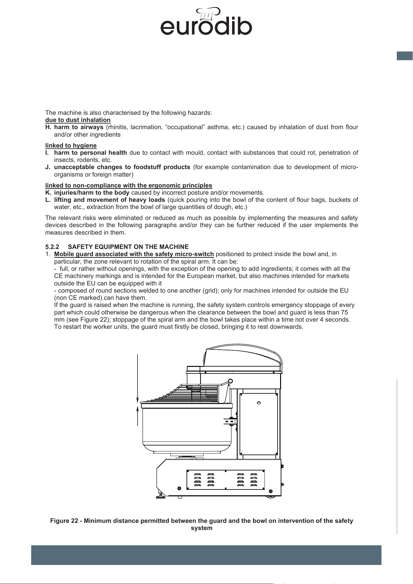
MADE IN ITALY
31
EN
spiral mixer xed bowl
40
The machine is also characterised by the following hazards:
due to dust inhalation
H. harm to airways (rhinitis, lacrimation, “occupational” asthma, etc.) caused by inhalation of dust from flour
and/or other ingredients
linked to hygiene
I. harm to personal health due to contact with mould, contact with substances that could rot, penetration of
insects, rodents, etc.
J. unacceptable changes to foodstuff products (for example contamination due to development of micro-
organisms or foreign matter)
linked to non-compliance with the ergonomic principles
K. injuries/harm to the body caused by incorrect posture and/or movements.
L. lifting and movement of heavy loads (quick pouring into the bowl of the content of flour bags, buckets of
water, etc., extraction from the bowl of large quantities of dough, etc.)
The relevant risks were eliminated or reduced as much as possible by implementing the measures and safety
devices described in the following paragraphs and/or they can be further reduced if the user implements the
measures described in them.
5.2.2 SAFETY EQUIPMENT ON THE MACHINE
1. Mobile guard associated with the safety micro-switch positioned to protect inside the bowl and, i
n
particular, the zone relevant to rotation of the spiral arm. It can be:
- full, or rather without openings, with the exception of the opening to add ingredients; it comes with all the
CE machinery markings and is intended for the European market, but also machines intended for markets
outside the EU can be equipped with it
- composed of round sections welded to one another (grid); only for machines intended for outside the E
U
(
non CE marked) can have them.
If the guard is raised when the machine is running, the safety system controls emergency stoppage of every
part which could otherwise be dangerous when the clearance between the bowl and guard is less than 75
mm (see Figure 22); stoppage of the spiral arm and the bowl takes place within a time not over 4 seconds.
To restart the worker units, the guard must firstly be closed, bringing it to rest downwards.
Figure 22 - Minimum distance permitted between the guard and the bowl on intervention of the safety
system
UNIMIX and SUPREME Spiral Mixers Use and maintenance instructions (translation of original instructions) - Ed. 01/2019
EFFEDUE S.R.L. Via dell’Artigianato, 10 36034 MALO (VI) - I
41
2. Fixed guards: they are guards kept locked by fastening elements which cannot be dismantled without using
equipment; if they are correctly assembled and fastened on the base, they particularly (but not only) make
the drive units moving the spiral arm and the bowl inaccessible. In detail (see Figure 23):
- the drive units moving the spiral arm are segregated using the guard ref. 1.
- the drive units moving the bowl are segregated using the guards ref. 2. (electric box and relevant closure
panel) and ref. 3.
The convergence zones of motion between the bowl pushing rollers (two, one per side) and the bowl are
protected by guards ref. 4 the position of which, you are reminded, must be such that their distance is not
over 4 mm).
The cover ref. 5 also acts as a fixed guard, combined with the interlocked guard, as per point 1, and the bowl
makes the rotating spiral arm inaccessible.
Lastly, guard ref. 6 is composed of two semi-cylindrical parts; once correctly assembled, it prevents insertion
of body parts between the lower part of the bowl and the bottom of the base frame; clearance between the
guard and the bottom must not be over 4 mm; check that this requirement is met in the event of dismantling
and subsequent reassembly of the guard in question (for example cleaning operations).
Figure 23 - Guards fixed with screws or similar devices
3. Hold-down command for bowl rotation (see par. 2.3).
It is a command that allows the operator to rotate the bowl (usually with a pulsed action) to bring the dough
to the best position, even from an ergonomic point of view, to remove it from the bowl.
When the operator stops activating the command (for example, by releasing the relevant button), the bowl
stops moving; by doing so, the operator has constant control over movement and has the possibility of
reducing ergonomic risk linked to movements and the force to extract the dough.
It is strictly forbidden to open/remove the guards and/or disable the safety devices unless for real and
mandatory needs and on implementation of the measures to eliminate or reduce related risks as much as
possible. Similar operations can only be carried out by expert and authorised staff. Re-assemble and block,
with the fastening devices planned, the guards and reactivate the safety devices as soon as the reasons for
their temporary removal/disabling has ceased. Anyone not complying with the above will be deemed fully liable
for any direct or indirect damage to people, animals or property which could result.
3
2
1
6
5
4
≤ 75 mm
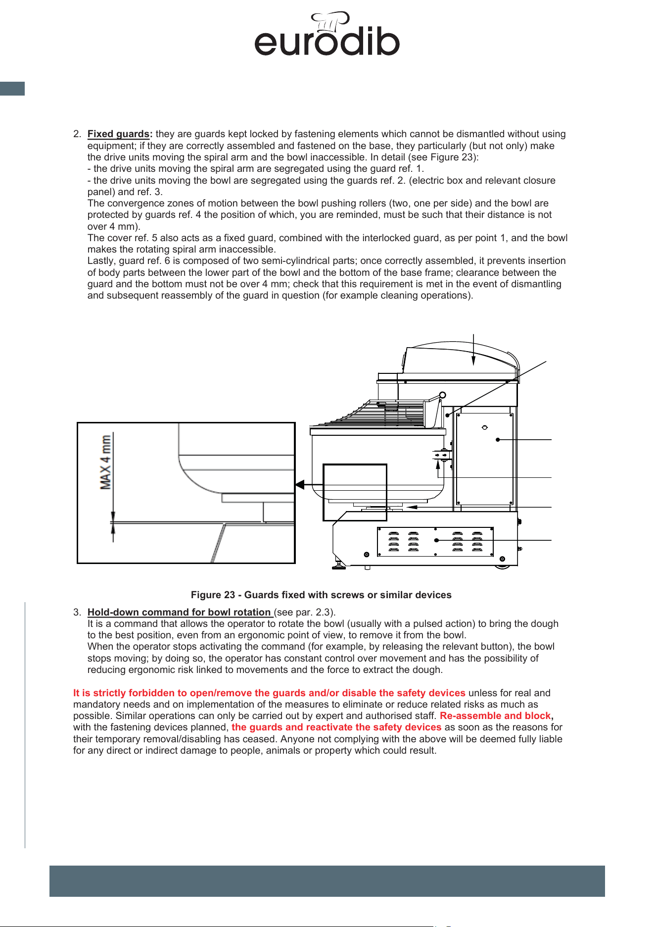
MADE IN ITALY
32
EN
spiral mixer xed bowl
UNIMIX and SUPREME Spiral Mixers Use and maintenance instructions (translation of original instructions) - Ed. 01/2019
EFFEDUE S.R.L. Via dell’Artigianato, 10 36034 MALO (VI) - I
40
The machine is also characterised by the following hazards:
due to dust inhalation
H. harm to airways (rhinitis, lacrimation, “occupational” asthma, etc.) caused by inhalation of dust from flour
and/or other ingredients
linked to hygiene
I. harm to personal health due to contact with mould, contact with substances that could rot, penetration of
insects, rodents, etc.
J. unacceptable changes to foodstuff products (for example contamination due to development of micro-
organisms or foreign matter)
linked to non-compliance with the ergonomic principles
K. injuries/harm to the body caused by incorrect posture and/or movements.
L. lifting and movement of heavy loads (quick pouring into the bowl of the content of flour bags, buckets of
water, etc., extraction from the bowl of large quantities of dough, etc.)
The relevant risks were eliminated or reduced as much as possible by implementing the measures and safety
devices described in the following paragraphs and/or they can be further reduced if the user implements the
measures described in them.
5.2.2 SAFETY EQUIPMENT ON THE MACHINE
1. Mobile guard associated with the safety micro-switch positioned to protect inside the bowl and, in
particular, the zone relevant to rotation of the spiral arm. It can be:
- full, or rather without openings, with the exception of the opening to add ingredients; it comes with all the
CE machinery markings and is intended for the European market, but also machines intended for markets
outside the EU can be equipped with it
- composed of round sections welded to one another (grid); only for machines intended for outside the EU
(non CE marked) can have them.
If the guard is raised when the machine is running, the safety system controls emergency stoppage of every
part which could otherwise be dangerous when the clearance between the bowl and guard is less than 75
mm (see Figure 22); stoppage of the spiral arm and the bowl takes place within a time not over 4 seconds.
To restart the worker units, the guard must firstly be closed, bringing it to rest downwards.
Figure 22 - Minimum distance permitted between the guard and the bowl on intervention of the safety
system
≤ 75 mm
41
2. Fixed guards: they are guards kept locked by fastening elements which cannot be dismantled without using
equipment; if they are correctly assembled and fastened on the base, they particularly (but not only) make
the
drive units moving the spiral arm and the bowl inaccessible. In detail (see Figure 23):
- the drive units moving the spiral arm are segregated using the guard ref. 1.
- the drive units moving the bowl are segregated using the guards ref. 2. (electric box and relevant clos
ure
pa
nel) and ref. 3.
The convergence zones of motion between the bowl pushing rollers (two, one per side) and the bowl
are
protec
ted by guards ref. 4 the position of which, you are reminded, must be such that their distance is not
over 4 m
m).
T
he cover ref. 5 also acts as a fixed guard, combined with the interlocked guard, as per point 1, and the bowl
makes the rotating spiral arm inaccessible.
Lastly, guard ref. 6 is composed of two semi-cylindrical parts; once correctly assembled, it prevents insertion
of body parts between the lower part of the bowl and the bottom of the base frame; clearance between the
guard and the bottom must not be over 4 mm; check that this requirement is met in the event of dismantling
an
d subsequent reassembly of the guard in question (for example cleaning operations).
Figure 23 - Guards fixed with screws or similar devices
3. Hold-down command for bowl rotation (see par. 2.3).
It is a command that allows the operator to rotate the bowl (usually with a pulsed action) to bring the dough
to
the best position, even from an ergonomic point of view, to remove it from the bowl.
When the operator stops activating the command (for example, by releasing the relevant button), the bowl
stops moving; by doing so, the operator has constant control over movement and has the possibility of
reducing ergonomic risk linked to movements and the force to extract the dough.
It is strictly forbidden to open/remove the guards and/or disable the safety devices unless for real and
mandatory needs and on implementation of the measures to eliminate or reduce related risks as much as
possible. Similar operations can only be carried out by expert and authorised staff. Re-assemble and block,
with the fastening devices planned, the guards and reactivate the safety devices as soon as the reasons for
their temporary removal/disabling has ceased. Anyone not complying with the above will be deemed fully liable
for any direct or indirect damage to people, animals or property which could result.
3
2
1
6
5
4
MADE IN ITALY
33
EN
spiral mixer xed bowl
42
5.2.3 EFFICIENCY CONTROLS ON SAFETY EQUIPMENT
The efficiency and integrity of the safety equipment, described in par. 5.2.2, must be checked at the start of
each day and/or work shift as follows:
1 Check the mobile guard on the bowl and the relevant safety micro-switch.
The check should be carried out with the bowl empty. Start the machine in speed 2; with the machine in motion,
raise the guard very slowly and stop as soon as you hear the micro-switch clicking or, however, when the guard
is far from the upper edge of the bowl less 75 mm; without inserting body parts between the guard and the
bowl, check that:
- the safety system intervenes commanding stoppage of each unit in motion when the guard is effectively
distance from the upper edge of the bowl less 75 mm (75 mm is an unacceptable value)
- the spiral arm and bowl stop within 4 seconds of intervention of the micro-switch associated with the guar
d;
us
e a stop watch, but if in doubt (e.g. because the time taken is very close to 4 seconds) the test must b
e
c
arried out by an expert electrician with suitable instrumentation (e.g. an oscilloscope)
- check that, after the stoppage command caused by guard opening and before closing the guard, it is not
po
ssible to execute any start command
If the control should have a negative outcome, do not use the machine and ask an expert, specialist
technician in electrical systems on the machine to intervene.
2 Fixed guards
Visually inspect they are all in position, in good condition (without accentuated dents, breakages, etc.) and
locked with all the fastening devices planned.
If the control should have a negative outcome, do not use the machine and ask an expert, specialist
mechanical technician in machine assembly; if necessary, contact the manufacturer.
3 Checks the hold-down command device for bowl rotation
The check should be carried out with the bowl empty and the guard closed. Activate and maintain the command
device activated. When the bowl is in motion, release the command device: the bowl must stop.
If the control should have a negative outcome, do not use the machine and ask an expert, specialist
technician in electrical systems on the machine to intervene.
5.2.4 RESIDUAL RISKS
Risk of catching and dragging between the bowl and base. The residual risk remains of catching and
dragging if a person inserts a part of their body in this space. The risk is greater, the more the thrust used by the
person to force passage (e.g. of an upper limb).
For the aforementioned reasons it is forbidden to bring your body parts closed to the danger zones in question
when the machine is in motion; if necessary, you are obliged to switch off the machine and disconnect the plug
from the electrical power supply.
Risk of crushing, shearing, dragging, impact in case of contact with moving spiral arm.
Despite the bowl
guard (whether full or grid) meeting the requirements of EN 453, there is still a remote possibility that a person
can reach the spiral arm in motion by passing through the open space between the guard and the bowl (< 75
mm), which forms by lifting the guard, before the safety micro-switch intervenes to command stoppage. Avoid
any attempt to reach the tool through this passage. Besides, there is no reasonably foreseeable reason to do so
and you would expose yourself pointlessly to serious safety risks.
A similar risk is created where the bowl guard is opened and you want to reach the spiral arm with rapid
movements of the arm, in particular when the bowl is empty. EN 453 allows a maximum stoppage time of 4
seconds, which is more than respected by the machine (new), which however also allows you to touch the tool
before it stops, in particular if the bowl is empty (the dough contributes to reducing the stoppage time).
Health risk of inhalation of flour dust;
see par. 3.4.1, points 2 - 4 - 10 and par. 4.8
Risk of muscle and skeleton injuries du
e to ergonomic factors; see par. 3.4.1, points 2 - 3 - 11)
The employer is responsible for providing operators with adequate information on residual risks that
machin
e use implies, as well as formation and training on its safe use, on the precautions to take and
on the behaviour to avoid (also see par. 3.5).
UNIMIX and SUPREME Spiral Mixers Use and maintenance instructions (translation of original instructions) - Ed. 01/2019
EFFEDUE S.R.L. Via dell’Artigianato, 10 36034 MALO (VI) - I
43
5.2.5 ELECTRICAL RISKS
The closure panel of the box ref. 8 Figure 1 and any other shell containing live parts has a specific sign affixed
to give a danger warning (see par. 5.3
). The risk is mostly linked to any accidental contact (impossible in normal
conditions) with live parts during the maintenance phases; as already stated time and time again, before
carrying out any intervention, you are obliged to open the main switch ref. 9
Figure 1 and disconnect the
plug Figure 11 from the electrical power supply; the disconnected plug must remain clearly visible so
that anyone can check electrical power to the machine is not connected.
ATTENTION! (only for machines equipped with an inverter)
Having sectioned and set the electrical power supply to zero, residual electrical voltage remains in the inverter
which could be very dangerous for personal safety if contact is made with the relevant parts with this voltage.
The display and the leds on the inverter stay on, until the DC BUS voltage (and therefore the relevant
capacitors) go under the value established by the manufacturer of the inverter, after which they switch off,
signalling the residual voltage should be below non-hazardous values.
In any case, once the electrical power supply is sectioned and set to zero, before touching (and, even
more so, before working on) parts of the inverter, terminations of it and electrical parts connected to it,
it is compulsory to:
- wait at least 10 minutes after switch-off of the display and the inverter leds
- use an appropriate tool to check there is no voltage on the motor terminals serviced by the inverter
Remember that all electrical interventions must only be carried out by expert and professionally trained
staff, capable of carrying out works to standard and with technical and legislative know-how for correct and safe
works.
5.2.6 INFORMATION ON NOISE EMITTED BY THE MACHINE
The machine operating with no load and at maximum speed emits a weighted acoustic pressure level A (LAeq)
clearly less than 70 dB[A].
5.3 SAFETY SIGNS
EFFEDUE affixes the following safety signs on the machine:
A
Danger of electrocution
(outside each shell with live electrical parts > 24 V inside)
B
ATTENTION! Danger of catching, dragging, crushing hands.
(on both sides of the machine near the risk zones B and C of par. 5.2.1)
C
It is forbidden to remove guards and/or disable the safety devices
(with reference to Figure 23 the guards ref. 1 and ref. 2)
D
It is forbidden to clean, lubricate, etc. units of the machine in motion
(on both sides of the machine near the risk zones B and C of par. 5.2.1; with reference
to Figure 23 ref. 1 and ref. 2)
ATTENTION! Check the images and colours of the signs are perfectly preserved; promptly replace them
on first sign of decay.
6 DISMANTLING
If you want to proceed to dismantle and dispose of the machine, separate its parts per type of material and
dispose of them in compliance with legislation and standards in force; the most important items are outlined
below.
Stai
nless steel: bowl, spiral arm, central tool, cover,
Painted or galvanised steel: support structure, fixed guards, motor support plates, casing of electric box
Cast iron: pulley
Plastic, rubber: drive belts, upper guards of head, bowl guard (arms in stainless steel)
Various material: motors (copper coils), electrical and electronic components
Extract the used lubricants, if existing, which should be disposed of separately.
F
or disposal, appoint a company specialising in waste disposal in compliance with legislation in force.
MADE IN ITALY
34
EN
spiral mixer xed bowl
UNIMIX and SUPREME Spiral Mixers Use and maintenance instructions (translation of original instructions) - Ed. 01/2019
EFFEDUE S.R.L. Via dell’Artigianato, 10 36034 MALO (VI) - I
42
5.2.3 EFFICIENCY CONTROLS ON SAFETY EQUIPMENT
The efficiency and integrity of the safety equipment, described in par. 5.2.2, must be checked at the start of
each day and/or work shift as follows:
1 Check the mobile guard on the bowl and the relevant safety micro-switch.
The check should be carried out with the bowl empty. Start the machine in speed 2; with the machine in motion,
raise the guard very slowly and stop as soon as you hear the micro-switch clicking or, however, when the guard
is far from the upper edge of the bowl less 75 mm; without inserting body parts between the guard and the
bowl, check that:
- the safety system intervenes commanding stoppage of each unit in motion when the guard is effectively
distance from the upper edge of the bowl less 75 mm (75 mm is an unacceptable value)
- the spiral arm and bowl stop within 4 seconds of intervention of the micro-switch associated with the guard;
use a stop watch, but if in doubt (e.g. because the time taken is very close to 4 seconds) the test must be
carried out by an expert electrician with suitable instrumentation (e.g. an oscilloscope)
- check that, after the stoppage command caused by guard opening and before closing the guard, it is not
possible to execute any start command
If the control should have a negative outcome, do not use the machine and ask an expert, specialist
technician in electrical systems on the machine to intervene.
2 Fixed guards
Visually inspect they are all in position, in good condition (without accentuated dents, breakages, etc.) and
locked with all the fastening devices planned.
If the control should have a negative outcome, do not use the machine and ask an expert, specialist
mechanical technician in machine assembly; if necessary, contact the manufacturer.
3 Checks the hold-down command device for bowl rotation
The check should be carried out with the bowl empty and the guard closed. Activate and maintain the command
device activated. When the bowl is in motion, release the command device: the bowl must stop.
If the control should have a negative outcome, do not use the machine and ask an expert, specialist
technician in electrical systems on the machine to intervene.
5.2.4 RESIDUAL RISKS
Risk of catching and dragging between the bowl and base. The residual risk remains of catching and
dragging if a person inserts a part of their body in this space. The risk is greater, the more the thrust used by the
person to force passage (e.g. of an upper limb).
For the aforementioned reasons it is forbidden to bring your body parts closed to the danger zones in question
when the machine is in motion; if necessary, you are obliged to switch off the machine and disconnect the plug
from the electrical power supply.
Risk of crushing, shearing, dragging, impact in case of contact with moving spiral arm. Despite the bowl
guard (whether full or grid) meeting the requirements of EN 453, there is still a remote possibility that a person
can reach the spiral arm in motion by passing through the open space between the guard and the bowl (< 75
mm), which forms by lifting the guard, before the safety micro-switch intervenes to command stoppage. Avoid
any attempt to reach the tool through this passage. Besides, there is no reasonably foreseeable reason to do so
and you would expose yourself pointlessly to serious safety risks.
A similar risk is created where the bowl guard is opened and you want to reach the spiral arm with rapid
movements of the arm, in particular when the bowl is empty. EN 453 allows a maximum stoppage time of 4
seconds, which is more than respected by the machine (new), which however also allows you to touch the tool
before it stops, in particular if the bowl is empty (the dough contributes to reducing the stoppage time).
Health risk of inhalation of flour dust; see par. 3.4.1, points 2 - 4 - 10 and par. 4.8
Risk of muscle and skeleton injuries due to ergonomic factors; see par. 3.4.1, points 2 - 3 - 11)
The employer is responsible for providing operators with adequate information on residual risks that
machine use implies, as well as formation and training on its safe use, on the precautions to take and
on the behaviour to avoid (also see par. 3.5).
43
5.2.5 ELECTRICAL RISKS
The closure panel of the box ref. 8 Figure 1 and any other shell containing live parts has a specific sign affixed
to give a danger warning (see par. 5.3
). The risk is mostly linked to any accidental contact (impossible in normal
conditions) with live parts during the maintenance phases; as already stated time and time again, before
carrying out any intervention, you are obliged to open the main switch ref. 9
Figure 1 and disconnect the
plug Figure 11 from the electrical power supply; the disconnected plug must remain clearly visible so
that anyone can check electrical power to the machine is not connected.
ATTENTION! (only for machines equipped with an inverter)
Having sectioned and set the electrical power supply to zero, residual electrical voltage remains in the inverter
which could be very dangerous for personal safety if contact is made with the relevant parts with this voltage.
The display and the leds on the inverter stay on, until the DC BUS voltage (and therefore the relevant
capacitors) go under the value established by the manufacturer of the inverter, after which they switch off,
signalling the residual voltage should be below non-hazardous values.
In any case, once the electrical power supply is sectioned and set to zero, before touching (and, even
more so, before working on) parts of the inverter, terminations of it and electrical parts connected to it,
it is compulsory to:
- wait at least 10 minutes after switch-off of the display and the inverter leds
- use an appropriate tool to check there is no voltage on the motor terminals serviced by the inverter
Remember that all electrical interventions must only be carried out by expert and professionally trained
staff, capable of carrying out works to standard and with technical and legislative know-how for correct and safe
works.
5.2.6 INFORMATION ON NOISE EMITTED BY THE MACHINE
The machine operating with no load and at maximum speed emits a weighted acoustic pressure level A (LAeq)
c
learly less than 70 dB[A].
5.3 SAFETY SIGNS
EURODIB affixes the following safety signs on the machine:
A
Danger of electrocution
(outside each shell with live electrical parts > 24 V inside)
B
ATTENTION! Danger of catching, dragging, crushing hands.
(on both sides of the machine near the risk zones B and C of par. 5.2.1)
C
It is forbidden to remove guards and/or disable the safety devices
(with reference to Figure 23 the guards ref. 1 and ref. 2)
D
It is forbidden to clean, lubricate, etc. units of the machine in motion
(on both sides of the machine near the risk zones B and C of par. 5.2.1; with reference
to Figure 23 ref. 1 and ref. 2)
ATTENTION! Check the images and colours of the signs are perfectly preserved; promptly replace them
on first sign of decay.
6 DISMANTLING
If you want to proceed to dismantle and dispose of the machine, separate its parts per type of material and
dispose of them in compliance with legislation and standards in force; the most important items are outlined
below.
Stai
nless steel: bowl, spiral arm, central tool, cover,
Painted or galvanised steel: support structure, fixed guards, motor support plates, casing of electric box
Cast iron: pulley
Plastic, rubber: drive belts, upper guards of head, bowl guard (arms in stainless steel)
Various material: mo
tors (copper coils), electrical and electronic components
Extract the used lubricants, if existing, which should be disposed of separately.
F
or disposal, appoint a company specialising in waste disposal in compliance with legislation in force.
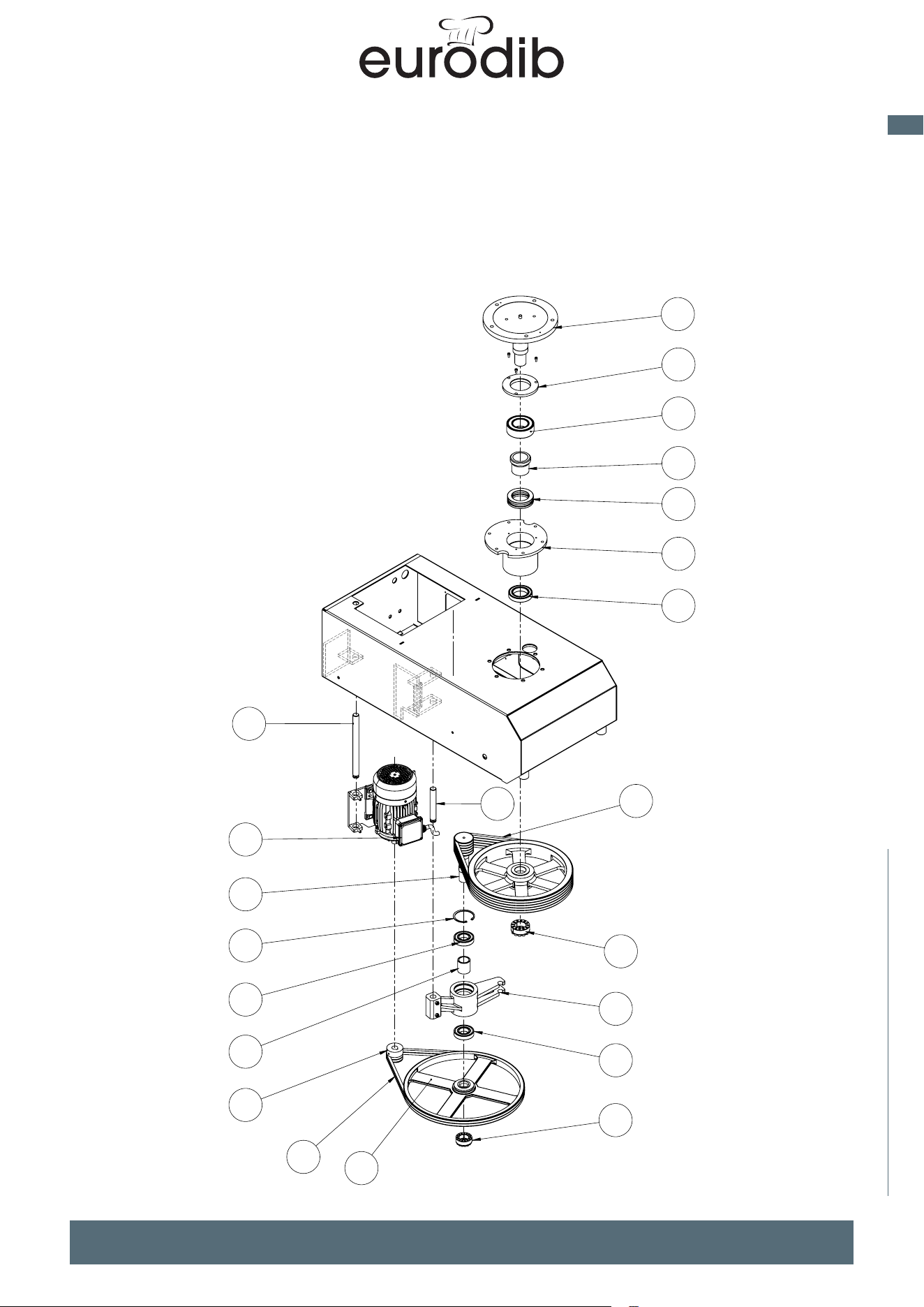
MADE IN ITALY
35
EN
spiral mixer xed bowl
1
2
3
4
5
6
7
8
9
10
11
12
13
14
15
16
17
18
13
19
20
21
1
4
5
6
5
8
3
7
2
2
9
9
223
11
10
SPARE PARTS
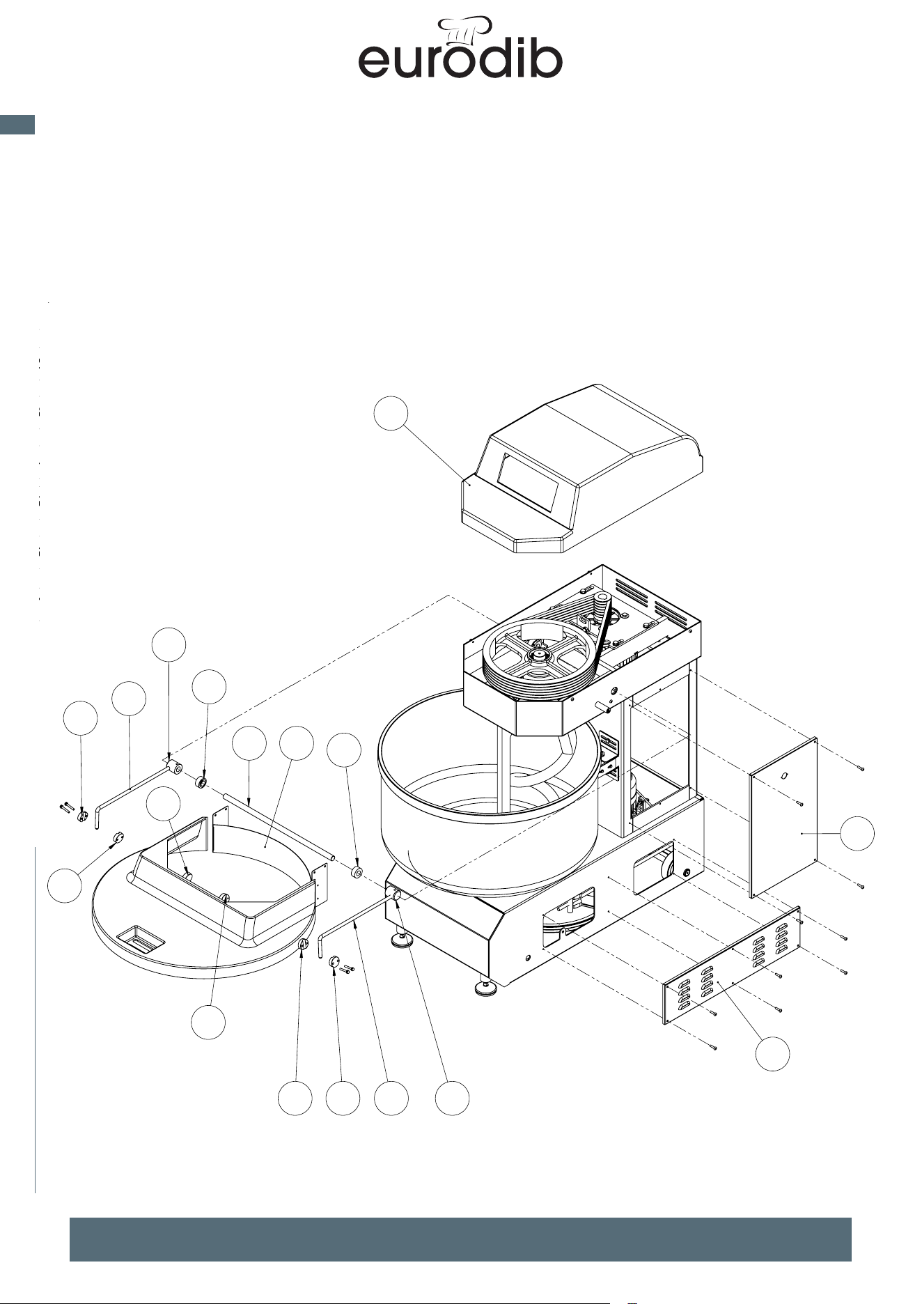
MADE IN ITALY
36
EN
spiral mixer xed bowl
1
2
3
4
5
6
7
8
9
10
11
12
13
14
15
16
17
18
13
19
20
21
1
4
5
6
5
8
3
7
2
2
9
9
223
11
10
SPARE PARTS
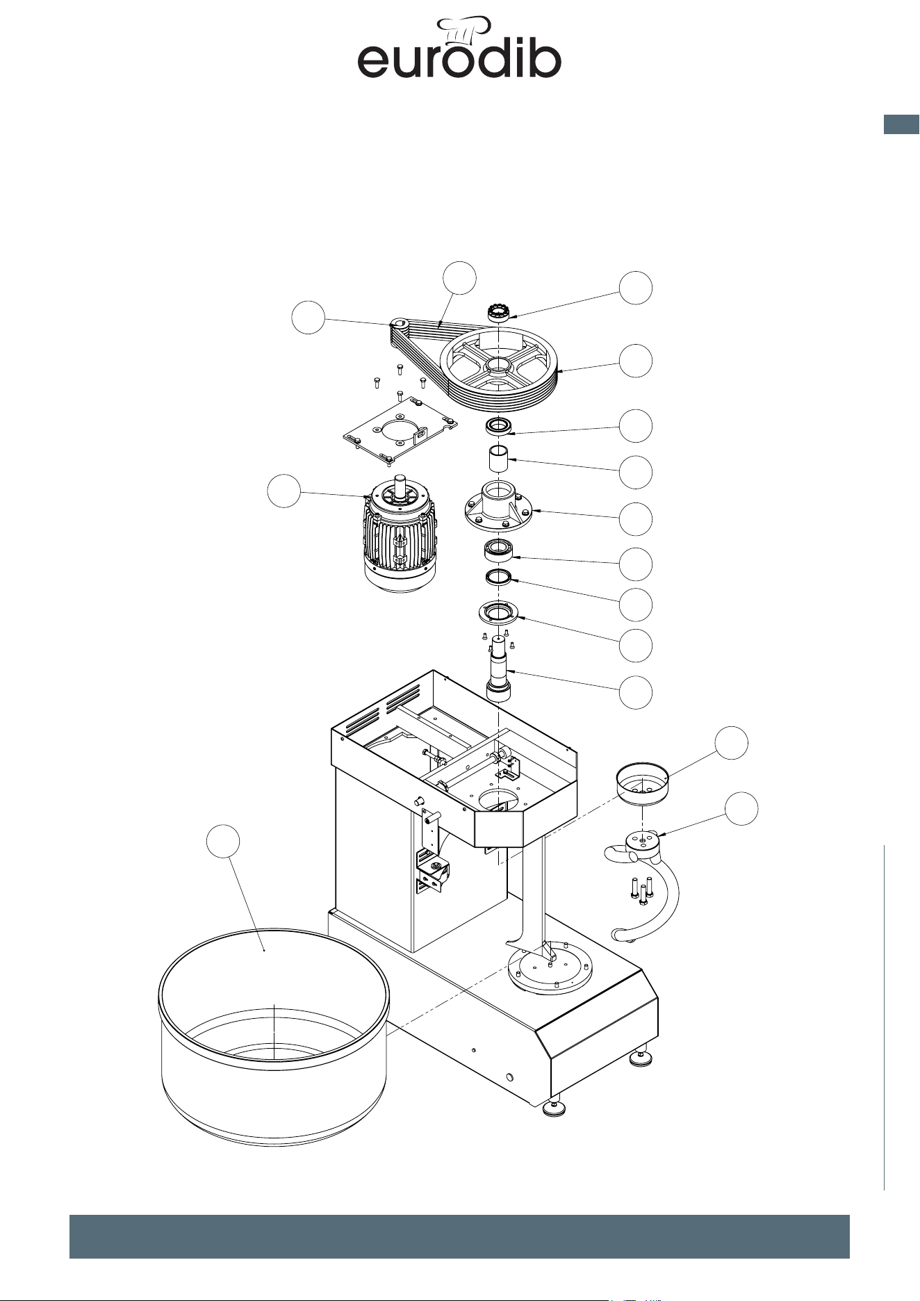
MADE IN ITALY
37
EN
spiral mixer xed bowl
SPARE PARTS
2
3
1
13
4
5
6
7
8
9
10
11
12
14
15
1
2
3
4
5
6
7
8
9
10
11
12
13
14
2
16
17
18
19
20
21
15
MSP JET/TS - TR
MSP JET/T
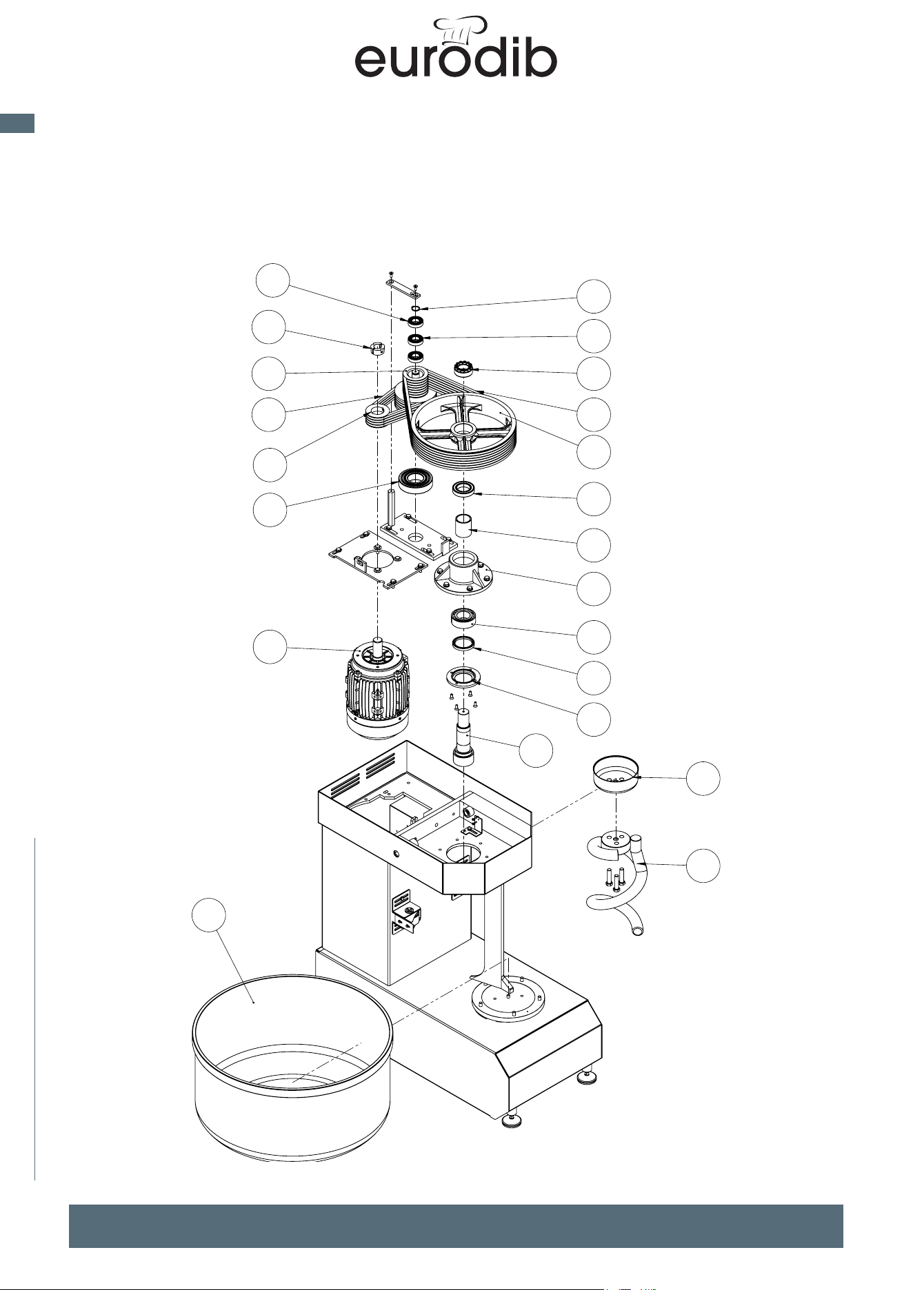
MADE IN ITALY
38
EN
spiral mixer xed bowl
SPARE PARTS
2
3
1
13
4
5
6
7
8
9
10
11
12
14
15
1
2
3
4
5
6
7
8
9
10
11
12
13
14
2
16
17
18
19
20
21
15
MSP JET/TS - TR
MSP JET/T
MADE IN ITALY
39
EN
spiral mixer xed bowl
WIRING DIAGRAM
Progetto:
Disegnatore:
Cliente:
Tensione esercizio:
Tensione ausiliari:
Frequenza:
Rev. Modifiche Data ApprovatoVerificatoPreparato
24 VAC
50-60 Hz
220-400V
Corrente nominale:
Potenza totale:
Grado di protezione:
Data:
MSP40-60 TIMER SITEC
DOPPIO MAC PAN
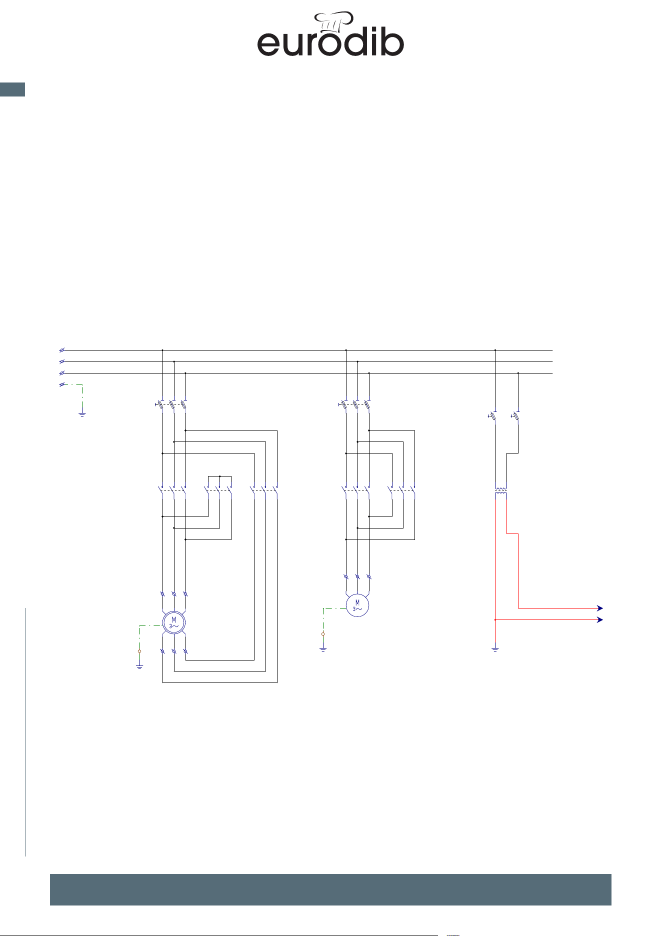
MADE IN ITALY
40
EN
spiral mixer xed bowl
WIRING DIAGRAM
TITOLO:
DATA:
PROGETTO:
FOGLIO
20/01/2009
MSP40-60 TIMER SITEC
DOPPIO MAC PAN
Potenza-Comando
2
CLIENTE:
DATA FIRMAREV. MODIFICA
DI
4
DIS.: Marco Busa
13
COMMESSA:
0 1 2 3 4 5 6 7 8 9
X
Y
Z
MOTORE SPIRALE
MOTORE VASCA
24
8
X1-L1
X1-L2
X1-L3
X1-
X1
X1-
X1
M1
U
V
W
X
Y
Z
X1-U X1-X
KM1
12
34
56
3.2
16AM
(10x38)
12
34
56
FU1
X1-V X1-Y
X1-W X1-Z
KM2
12
34
56
3.4
KM3
12
34
56
3.5
X1-
X1
12
34
56
KM4
3.7
M2
X1-X1
6AM
(10x38)
12
34
56
FU2
X1-Y1
X1-Z1
12
34
56
KM5
3.7
X1
2A GL
(10x38)
12
FU3
T1
0V0V
400V24V
2A GL
(10x38)
12
FU4
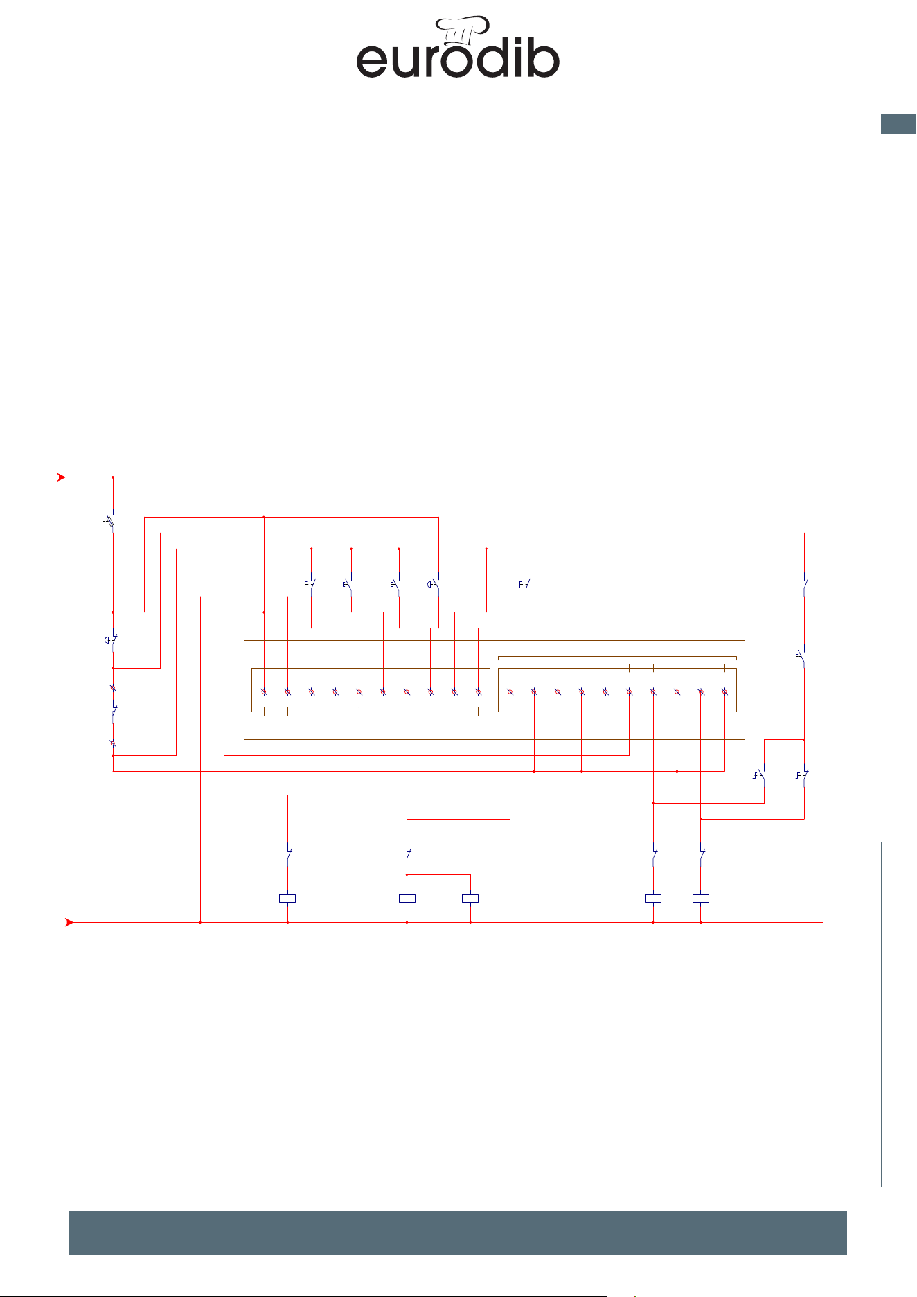
MADE IN ITALY
41
EN
spiral mixer xed bowl
WIRING DIAGRAM
TITOLO:
DATA:
PROGETTO:
FOGLIO
20/01/2009
MSP40-60 TIMER SITEC
DOPPIO MAC PAN
Potenza-Comando
3
CLIENTE:
DATA FIRMAREV. MODIFICA
DI
4
DIS.: Marco Busa
24
COMMESSA:
0 1 2 3 4 5 6 7 8 9
3.9
14
13
12
6
1
23
6
15
1
1
8
9
25
5
4
16
7
18 1917
24 24
6
7
1
6
2
ALIMENTAZIONE INGRESSI
SPIRALE VASCA
USCITE
SQ1
7
X1
6
X1
12
SB1
3-4 3.4
10A GL
(10x38)
12
FU5
1 10 11 12 13 14 15 16 17 18 192 203456789
KT1
2122
KM2
3.4
A1A2
KM1
j
j
j
b
b
2.11 2
2.13 4
2.15 6
3.421 22
3.9
61 62
12
SA2
3-4 3.8
1-2 3.9
34
SB2
34
SB3
2122
KM1
3.2
A1A2
KM2
j
j
j
b
2.21 2
2.23 4
2.25 6
3.221 22
34
SB1
3.0
A1A2
KM3
j
j
j
2.31 2
2.33 4
2.35 6
12
SA1
2122
KM5
3.7
A1A2
KM4
j
j
j
b
2.41 2
2.43 4
2.45 6
3.721 22
2122
KM4
3.7
A1A2
KM5
j
j
j
b
2.51 2
2.53 4
2.55 6
3.721 22
34
SA2
3.3
6162
KM1
3.2
34
SB4
12
SA2
3.3
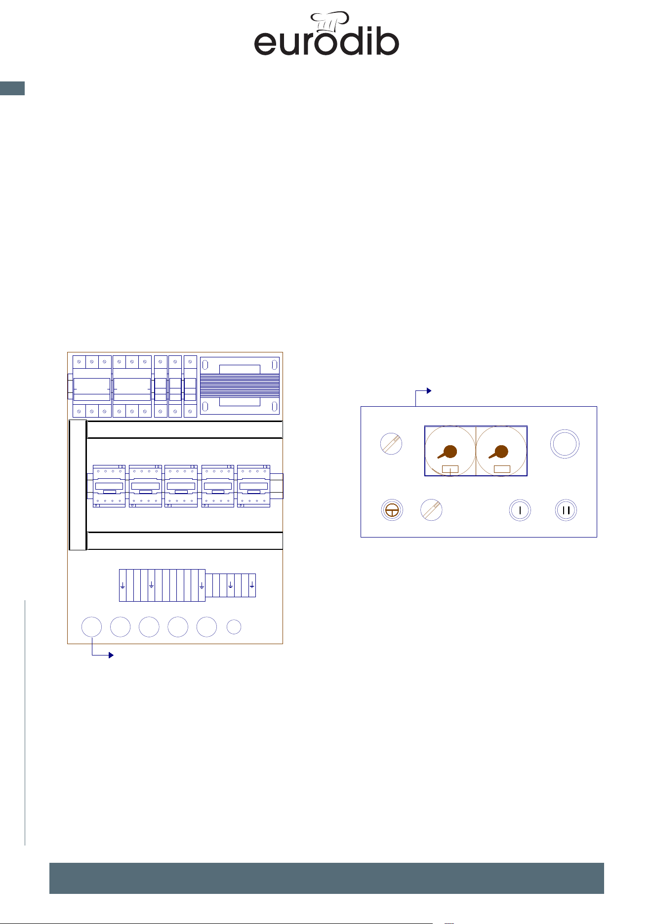
MADE IN ITALY
42
EN
spiral mixer xed bowl
WIRING DIAGRAM
TITOLO:
DATA:
PROGETTO:
FOGLIO
20/01/2009
MSP40-60 TIMER SITEC
DOPPIO MAC PAN
Layout Quadro
4
CLIENTE:
DATA FIRMAREV. MODIFICA
DI
4
DIS.: Marco Busa
3
COMMESSA:
10
0 20 0 20
10
L1
L2
L3
X
Y
Z
U
V
W
X1
Y1
Z1
7
6
TC1
USCITA FILI M40-60 105cm
KT1
SA2
SA1 SB2 SB3
SB4
SB1
USCITA FILI 45cm
FU3
FU1 FU2 FU5FU4
KM4 KM5KM1 KM2 KM3
MADE IN ITALY
43
EN
spiral mixer xed bowl
WIRING DIAGRAM
Progetto:
Disegnatore:
Cliente:
Tensione esercizio:
Tensione ausiliari:
Frequenza:
Rev. Modifiche Data ApprovatoVerificatoPreparato
MSP80-250 TIMER SITEC
DOPPIO MAC PAN
24 VAC
50-60 Hz
220-400V
Corrente nominale:
Potenza totale:
Grado di protezione:
Data:
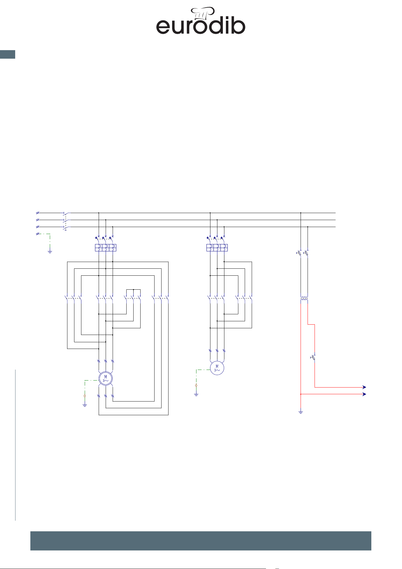
MADE IN ITALY
44
EN
spiral mixer xed bowl
WIRING DIAGRAM
TITOLO:
DATA:
PROGETTO:
FOGLIO
26/04/2022
MSP80-250 TIMER SITEC DOPPIO MAC PAN
Potenza-Comando
2
CLIENTE:
DATA FIRMAREV. MODIFICA
DI
4
DIS.: Marco Busa
13
COMMESSA:
0 1 2 3 4 5 6 7 8 9
X
Y
Z
MOTORE SPIRALE
MOTORE VASCA
8
21
24
X1-L1
X1-L2
X1-L3
X1-
X1
12
34
56
QS1
12
34
56
KMF
3.6
X1-
X1
12
34
56
QF1
43-44 3.0 \{}\
M1
U
V
W
X
Y
Z
X1-U X1-X
KM1
12
34
56
3.2
X1-V X1-Y
X1-W X1-Z
KM2
12
34
56
3.4
KM3
12
34
56
3.5
X1-
X1
12
34
56
QF2
43-44 3.0 \{}\
12
34
56
KM4
3.7
M2
U
V
W
X1-X1
X1-Y1
X1-Z1
12
34
56
KM5
3.7
X1
T1
0V0V
400V24V
12
2A GL
(10x38)
12
FU1
10A GL
(10x38)
12
FU2
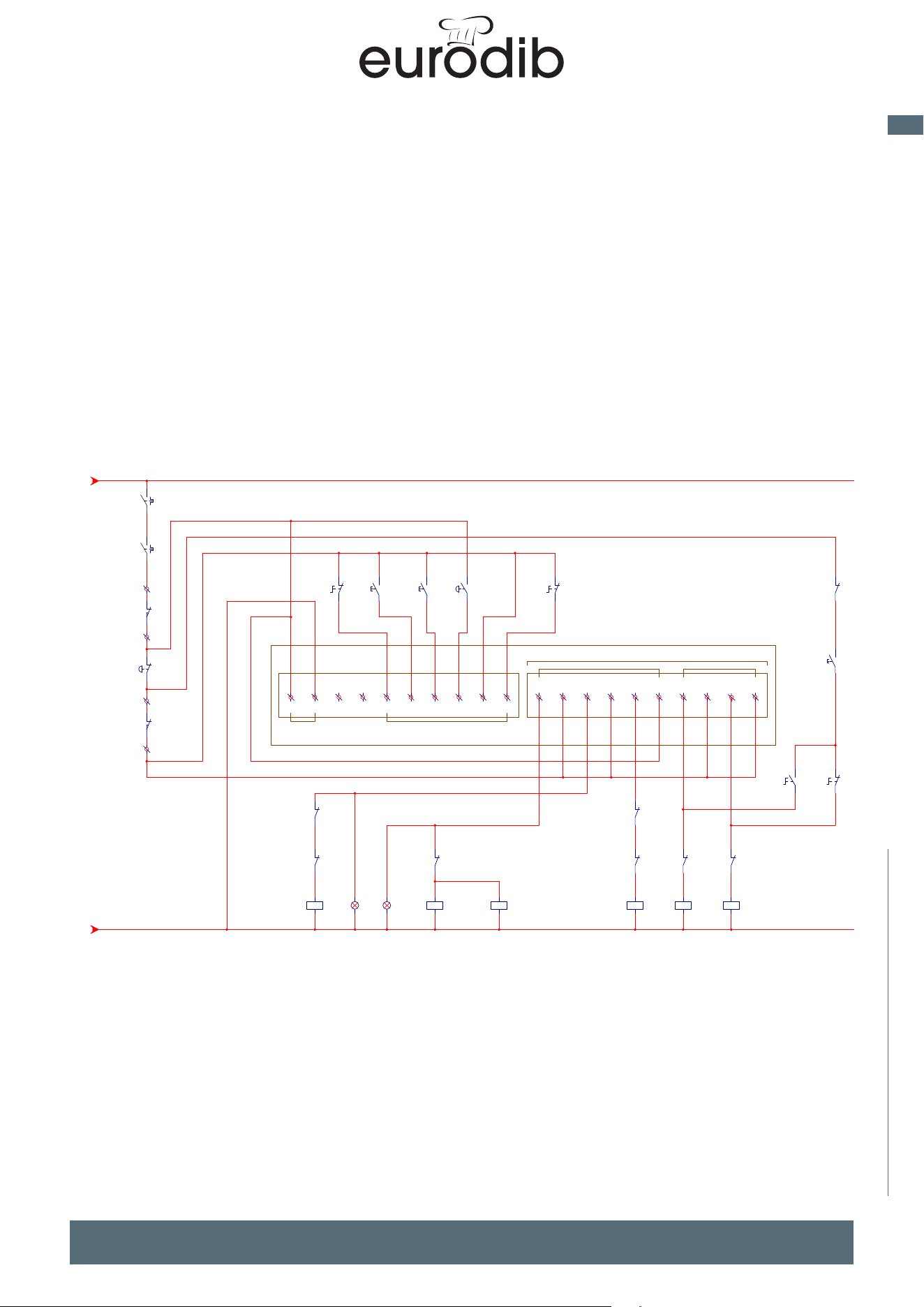
MADE IN ITALY
45
EN
spiral mixer xed bowl
WIRING DIAGRAM
TITOLO:
DATA:
PROGETTO:
FOGLIO
26/04/2022
MSP80-250 TIMER SITEC DOPPIO MAC PAN
Potenza-Comando
3
CLIENTE:
DATA FIRMAREV. MODIFICA
DI
4
DIS.: Marco Busa
24
COMMESSA:
0 1 2 3 4 5 6 7 8 9
3.9
21
14
13
12
6
1
23
6
15
1
1
6
8
8
9
25
5
4
2
16
3
20
7
18 1917 22
10
28
7
6
21
26
1
27
ALIMENTAZIONE INGRESSI
SPIRALE VASCA
USCITE
4344
QF1
2.1
44
QF2
43
2.4
FC
SQ2
7
X1
6
X1
12
SB1
3-4 3.4
ALIM
SQ1
27
X1
1
X1
1 10 11 12 13 14 15 16 17 18 192 203456789
KT1
2122
KM2
3.4
2122
KMF
3.6
A1A2
KM1
j
j
j
b
b
2.11 2
2.13 4
2.15 6
3.421 22
3.961 62
12
SA2
3-4 3.8
1-2 3.9
X1X2
HL1
34
SB2
X1X2
HL2
34
SB3
2122
KM1
3.2
A1A2
KM2
j
j
j
b
b
2.21 2
2.23 4
2.25 6
3.221 22
3.661 62
34
SB1
3.0
A1A2
KM3
j
j
j
b
2.31 2
2.33 4
2.35 6
3.621 22
12
SA1
2122
KM3
3.5
A1A2
KMF
j
j
j
b
2.11 2
2.13 4
2.15 6
3.221 22
6162
KM2
3.4
2122
KM5
3.7
A1A2
KM4
j
j
j
b
2.41 2
2.43 4
2.45 6
3.721 22
2122
KM4
3.7
A1A2
KM5
j
j
j
b
2.51 2
2.53 4
2.55 6
3.721 22
34
SA2
3.3
6162
KM1
3.2
34
SB4
12
SA2
3.3
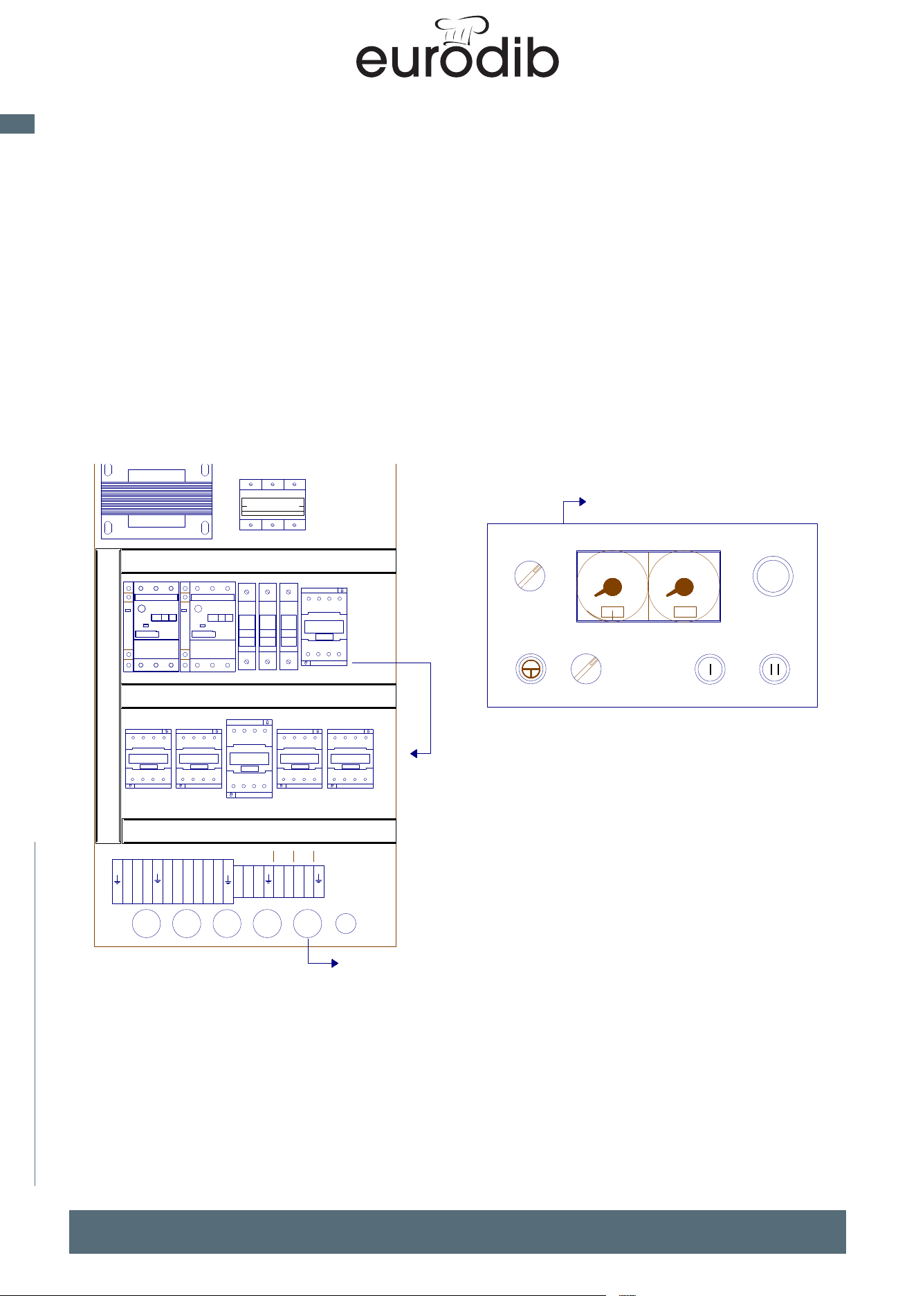
MADE IN ITALY
46
EN
spiral mixer xed bowl
WIRING DIAGRAM
TITOLO:
DATA:
PROGETTO:
FOGLIO
26/04/2022
MSP80-250 TIMER SITEC DOPPIO MAC PAN
Layout Quadro
4
CLIENTE:
DATA FIRMAREV. MODIFICA
DI
4
DIS.: Marco Busa
3
COMMESSA:
10
0 20 0 20
10
ALIM
FC
27
1
QS1
KMF
FU1
FU2
FU1
QF2
L1
L2
L3
X
Y
Z
U
V
W
X1
Y1
Z1
7
6
TC1
USCITA FILI M80-130 165cm
USCITA FILI M160-250 195cm
NELLE
M160-250
KT1
SA2
SA1 SB2 SB3
SB4
SB1
USCITA FILI 45cm
KM4 KM5
KM1
KM2
KM3
QF1


www.eurodib.com