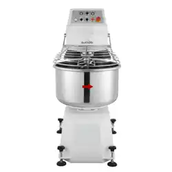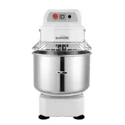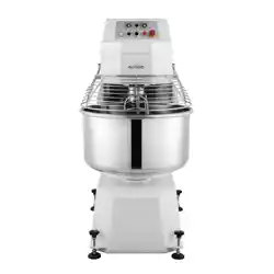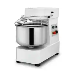
LB Series Spiral Mixers
Operation Manual
Model: LB20/LB30/LB40/LB50/LB60

LB Series Spiral Mixers
Attention
• New use or repair of this product must be performed by experts or by a qualified person or those who have
obtained the license of installation, or those who are authorized by the manufacturer.
• When performing installation or maintenance, please follow the following instructions carefully to ensure the safe
use of this appliance.
• Put off the package to make sure none of the parts is missing or damaged. If there is any doubt about the
product, please do not use it. Consult an expert.
• This appliance should only be operated by a person who is familiar with the unit.
• When not in use or if the operator is absent, please turn off the power to avoid any accidental injury or damage.
• When if it needs to be repaired, please consult an expert, and use original spare parts. It will be dangerous if you
do not follow the above requirements.
• Clean stainless-steel surfaces periodically with appropriate method to prevent any damage brought by oxidation
or any other chemical interference.
1. DESCRIPTION
The LB Series Spiral Mixer offers efficient and thorough mixing for a variety of tasks. Its innovative design combines several
features to achieve this:
• The spiral, dough hook, and material barrel all rotate together, significantly reducing mixing times.
• A frequency converter allows you to adjust the mixing intensity for different ingredients, ensuring optimal results.
• The multi-v belt and pulley drive system is known for its reliability and long lifespan, keeping the mixer running
smoothly for years to come.
• The compact design maximizes your workspace, while the protective cover and intuitive controls promote safe
operation.
• This versatility makes the LB Series Spiral Mixer suitable for a wide range of applications, including food preparation
in hotels, restaurants, and food processing plants, as well as raw material preparation in pharmaceutical and
chemical plants.
2. INTERPRETATION
We reserve the right to change product designs without notice. While every effort is made to ensure that publications reflect
the latest designs, the company cannot guarantee exact correspondence.
Technical
specification
name
Barrel
capacity
(oz)
Maximum
flour capacity
(lbs)
Hook
speed
(r/min)
Barrel
speed
(r/min)
Power
(kw)
Voltage
(V/Hz)
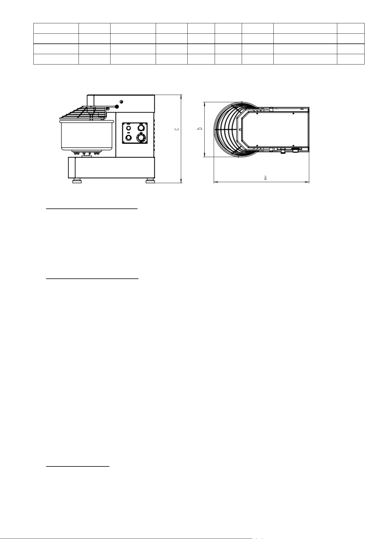
Size: WxDxH
(inches)
Net
weight
(lbs)
LB20
676,3
17,6
140-240
17-27
0.75
110/60
27,6” x 15,7” x 24,8”
132,3
3. GENERAL INFORMATION
This manual provides information and descriptions for the LB Series Spiral Mixer. It may not cover every detail or variation
of the equipment, nor may it address every situation that may arise during installation or use.
If you require further information, please contact us.
4. SECURITY INFORMATION
• The following procedures and instructions should always be followed to prevent injury.
• If the machine is not used as recommended, the operator is responsible for the safety of himself and others who
may be involved.
• The information in this manual is designed to help the operator properly understand, maintain, and operate the
pasta machine.
• To prevent accidents, please make sure you read, understand, and follow the instructions in this manual prior to
installation or operation. This manual must be read carefully.
• Rotating machinery and electricity are dangerous and can cause injury if proper precautions are not taken before
operating or servicing the mixer. Ensure that power is disconnected from the mixer and isolated before cleaning or
servicing the machine. In some troubleshooting situations, it may be necessary to operate the mixer.
• In such cases extra care must be taken. Only qualified personnel should service the mixer.
4.1 SAFETY GUIDELINES
Ensure that sufficient precautions are observed when manually handling the mixer, particularly when moving the mixer into
position or installation. Ensure to comply with manual handling regulations.
• This appliance is only for commercial and not for domestic use.
LB30
1014,4
26,5
140-240
17-27
1.1
220/60
29,1” x 17,3” x 26,7”
160,9
LB40
1352,6
35,3
140-240
17-27
2.2
220/60
34” x 18,9” x 29,9”
242,5
LB50
1690,7
44,1
140-240
17-27
2.5
220/60
35,8” x 21,1” x 29,9”
264,5
LB60
2028,8
55,1
140-240
17-27
3
220/60
35,8” x 21,1” x 32,3”
286,6

• The mixer is not intended for use by children.
• While the machine is in operation, do not remove any cover.
• When mixing products that develop dust, extreme care must be taken.
• Exposure to dust (including flour) may be harmful to health and cause rhinitis (running nose), watery eyes and
possibly occupational asthma.
• If dust is a hazard, ensure that appropriate PPE (personal protective equipment) is used by operators, i.e., a mask.
• All operators must be trained in the safe operation of the mixer and attachments.
• This appliance is not to be used by anyone who with a lack of knowledge. Ensure that all operators have been
appropriately trained.
• This appliance is not intended to be used by those whose sensory, physical, or mental capabilities prevent them
from being able to operate it safely.
• Ensure that the electrical supply has been isolated and the power cord disconnected before attempting to move or
service the mixer.
• Be aware of the start capacitor situated behind the rear motor cover. In normal circumstances this should discharge
when the mixer is switched off. In case of doubt, discharge the capacitor following adequate safety precautions.
• When accessing electrical components inside the mixer, be cautious of exposed conductors that could be 'live'.
• Always have your mixer and attachments regularly serviced, that is at least twice a year, depending on the frequency
of use.
• Ensure that this manual is kept in an easily accessible place near the mixer for future reference.
4.2 SAFETY INSTRUCTIONS
A FULLY TRAINED AND COMPETENT PERSON MUST ONLY USE THE ATTACHMENT AND/OR MIXER.
When maneuvering or lifting a bowl and its contents with a total weight more than 500 kg, a bowl truck must be used. As
far as reasonably possible, avoid tasks concerned with manual handling that involves a risk to health. This equipment
should only be stored in or transported through an environment with an ambient temperature above 5°C and below 55°C.
Note: The mixer must only be used to the purpose for which it was designed and in line with operating instructions.
When mixing ingredients, care must be taken to avoid the inhalation of dust particles e.g. flour. Reference should be made
to product supplier's data sheets to ensure adequate precautions and protections are taken.
The following instructions must be observed when operating the mixer
4.3 NEVER
• Wear loose clothing that may become caught in the mixer while it is in operation.
• Attempt to reach into the bowl while it is mixing.
• Access rotating parts.
• Use excessive force when operating which could affect the stability of the mixer.
• Operate the mixer if parts are disassembled.
• Override safety switches fitted to the mixer.
• Open the guard to stop the machine.
• Use the mixer in an unsafe condition.
• Operate the mixer or attachment if a fault develops or if the mixer is unsafe.
• Attempt to repair the appliance. A qualified technician must service the machine.
4.4 ALWAYS
• Use the mixer as intended and in line with the operating instructions.
• Use the mixer in a well-lit area.
• Stop the mixer before adding more ingredients.
• Use the stop button to stop machine.
• Disconnect the mains electricity supply before cleaning the mixer.
• Clean the bowl, agitators and after use.
• Clean the mixer using mild soap and water.
• Clean the mixer daily.
• Inspect the power cable and appliance regularly. If a fault is found, do not operate.
• Disconnect the main electricity supply before cleaning the mixer.
4.5 RESPONSIBILITY
Installations and repairs which are not carried out by authorized technicians or the use of other than original spare
parts, and any technical alterations to the machine, may affect the warranty set out in the standard conditions of sale.
ATTENTION! DO NOT hose or pressure clean this appliance. It is vital to follow the cleaning procedures detailed later
in section 7 of this manual.
5. OPERATION AND PRECAUTIONS
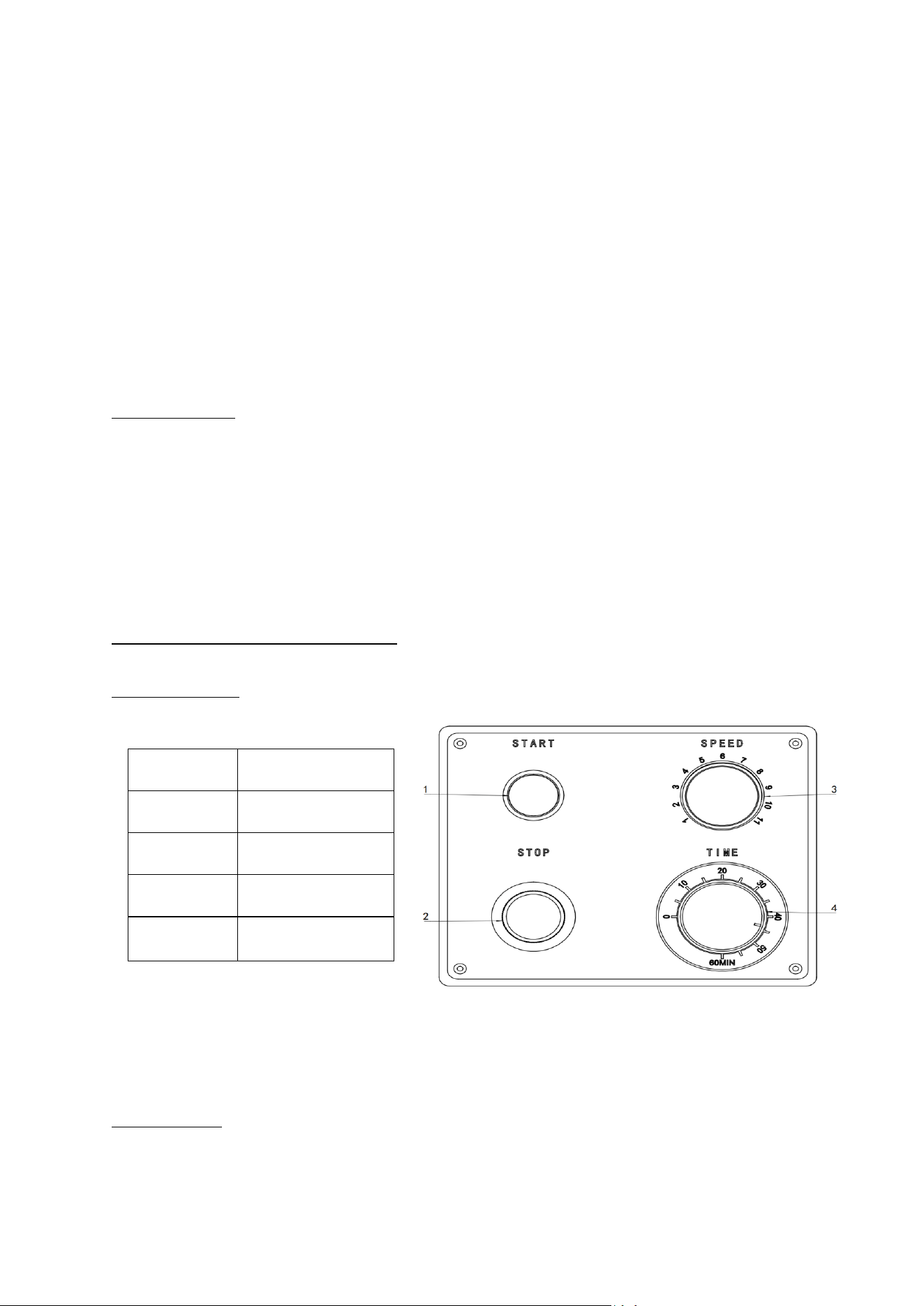
5.1 CONTROL PANEL
5.2 PRECAUTIONS
• Place the machine on the horizontal floor, keep it stable, and maintain the environment in a suitable temperature.
• Check whether the power supply corresponds to what the machine requires, and whether wires are connected
properly.
Serial number
Name
1
Start button
2
Stop Button
3
Speed control button
4
Timer button
Warning: The machine must be grounded properly (the user’s power supply must come with a ground wire).
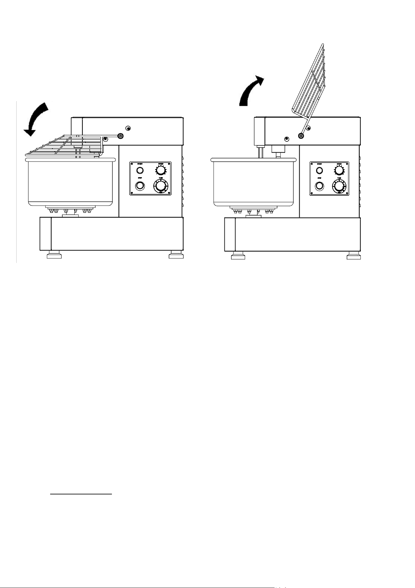
• Check the protective cover.
A. Open the protective cover. Use suitable flour into the bowl every time (the capacity of the flour can’t exceed the
determined maximum).
B. Fill the bowl with water. Water weight is equal to 45%-50% of the required flour weight.
C. Put down the protective cover and start the machine.
D. When the dough has been kneaded (probably for 8 minutes), push stop button to stop the machine. Open the
protective cover and take out the dough.
E. When the machine is working, it is forbidden to put one’s hands or a hard object into the bowl and taking out the dough
with one’s hands is dangerous.
F. During working, do not clean, oil, or lubricate the machine.
6. MAINTENANCE
Important: All machine work should be carried out after having unplugged the machine.
During service and maintenance, the motor and parts should be dismounted gradually. The machine should be cleaned,
and chains and bearings should be lubricated regularly.
Advice:
A. After each use, clean the machine carefully. Make sure to keep the machine clear and to pour lubricating oil into
lubrication points.
B. Do not start the machine repeatedly to prolong the machine’s lifetime. The continuous running time should not be too
long.
C. Lubricate chains and main moving parts about once a mouth.
D. Check belt and chain tension about once every six months.
E. Check the electric circuit about once a year.
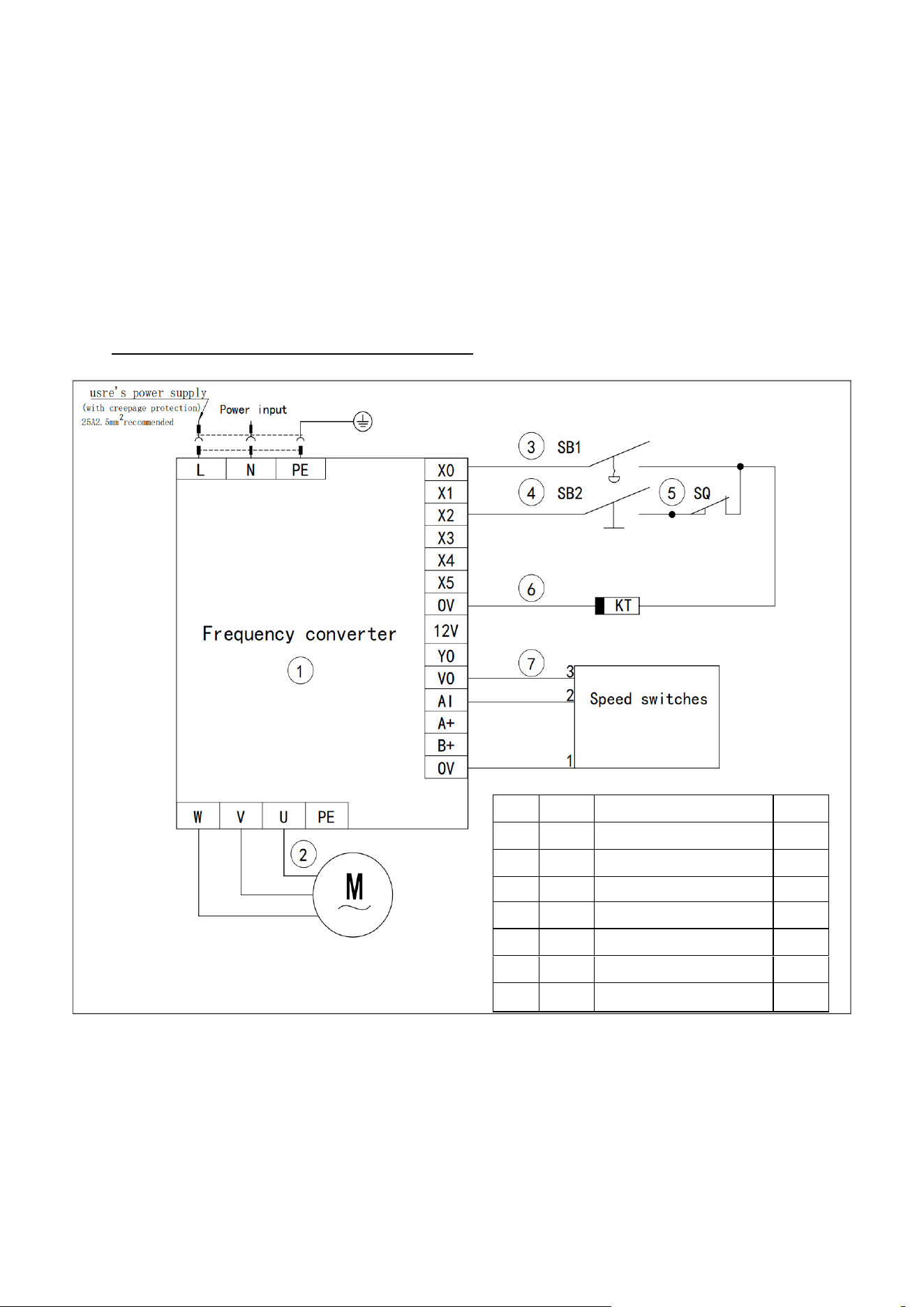
6.1 LB20 30 40 50 60 Circuit diagram (single phase)
NO
Code
Name
Qty
①
Frequency converter
1
②
M
Motor
1
③
SB1
Emergency Stop button
1
④
SB2
Start Button with light
1
⑤
SQ
Travel switch
1
(6)
KT
Time switch
1
(7)
Speed switch
1
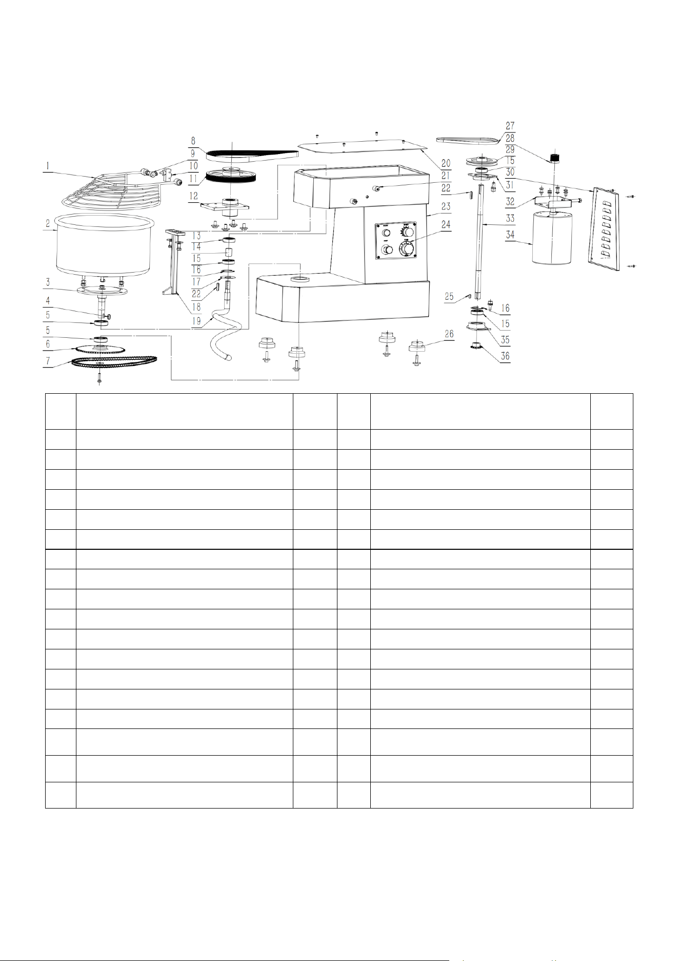
LB20 machine description
If you need to replace the parts, you can use the parts list below to let us know your requirements.
NO.
Name of part
Qty
NO.
Name of part
Qty
1
Net cover
1
19
Screw hook
1
2
Face barrels (20L)
1
20
Upper cover plate
1
3
Lower shaft
1
21
Eccentric shaft sleeve
3
4
8*20 Square key
1
22
6*32 Square key
1
5
Grooved ball bearing (6205/1204)
4
23
Housing
1
6
Output sprocket
1
24
Control panel
1
7
Chain (47section)
1
25
6*16 Square key
1
8
Multiple V-belt (9R)
1
26
Rubber foot
4
9
Fixed bushing
1
27
Deltoid
1
10
Shift switch
1
28
V-belt (9R)
1
11
Multiple V-belt pulley (9R)
1
29
V-belt pulley
1
12
Upper bearing seat
1
30
Rear cover plate
1
13
Grooved ball bearing (6303)
1
31
Upper bearing seat
1
14
Bearing spacer
1
32
Motor adjustment base
1
15
Deep groove ball bearing (6205)
1
33
Central axis
1
16
Circlip (47)
2
34
Electric machine (0.75KW)
1
17
Oil seal cover
1
35
Lower bearing seat
1
18
Center pole
1
36
Drive pinion
1
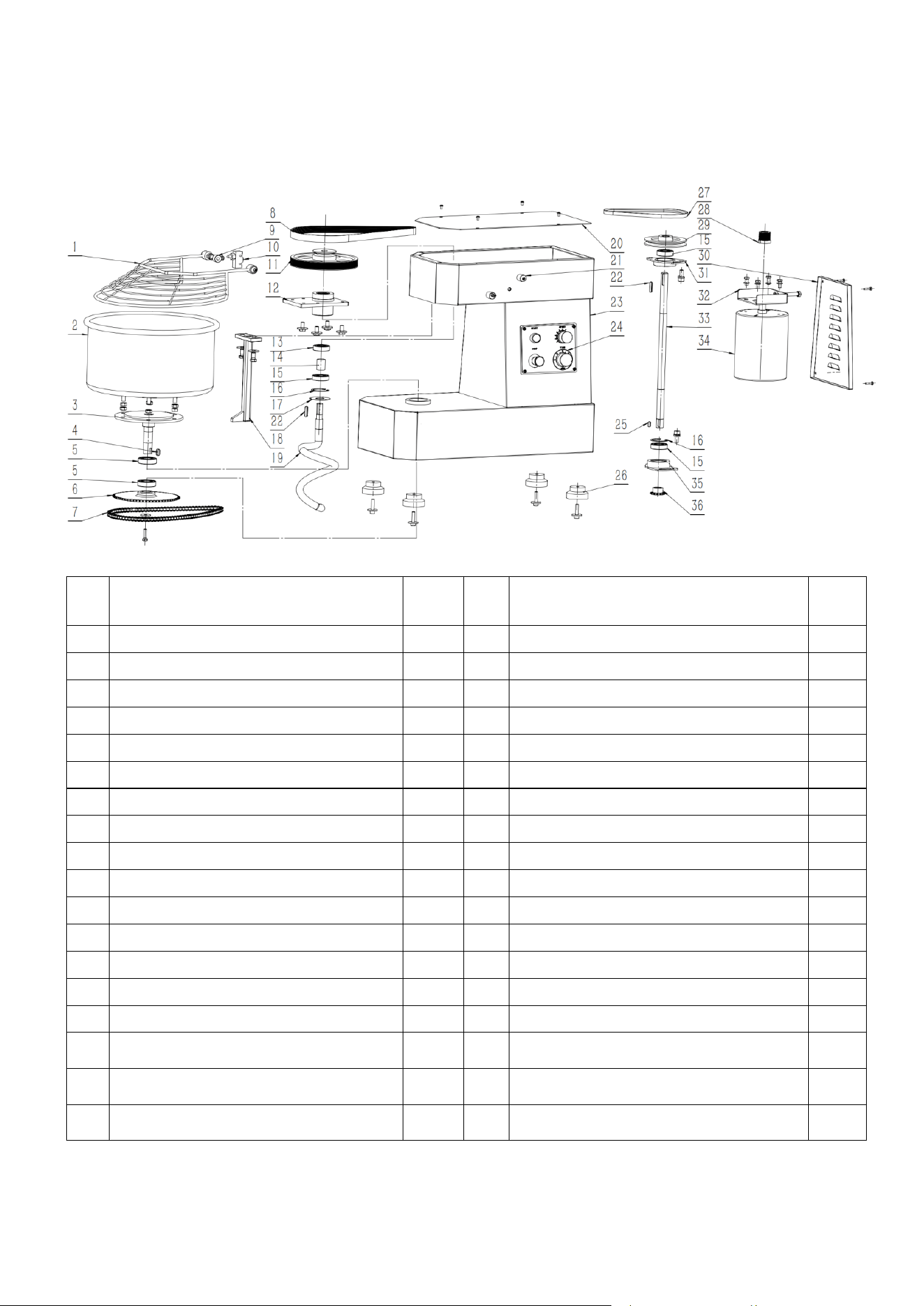
LB30 machine description
If you need to replace the parts, you can use the parts list below to let us know your requirements.
NO.
Name of part
Qty
NO.
Name of part
Qty
1
Net cover
1
19
Screw hook
1
2
Face barrels (30L)
1
20
Upper cover plate
1
3
Lower shaft
1
21
Eccentric shaft sleeve
3
4
8*20 Square key
1
22
6*32 Square key
1
5
Grooved ball bearing (6205/1204)
4
23
Housing
1
6
Output sprocket
1
24
Control panel
1
7
Chain (50 section)
1
25
6*16 Square key
1
8
Multiple V-belt (9R)
1
26
Rubber foot
4
9
Fixed bushing
1
27
Deltoid
1
10
Shift switch
1
28
V-belt (9R)
1
11
Multiple V-belt pulley (9R)
1
29
V-belt pulley
1
12
Upper bearing seat
1
30
Rear cover plate
1
13
Grooved ball bearing (6303)
1
31
Upper bearing seat
1
14
Bearing spacer
1
32
Motor adjustment base
1
15
Deep groove ball bearing (62/22)
1
33
Central axis
1
16
Circlip (50)
2
34
Electric machine (1.1KW)
1
17
Oil seal cover
1
35
Lower bearing seat
1
18
Center pole
1
36
Drive pinion
1
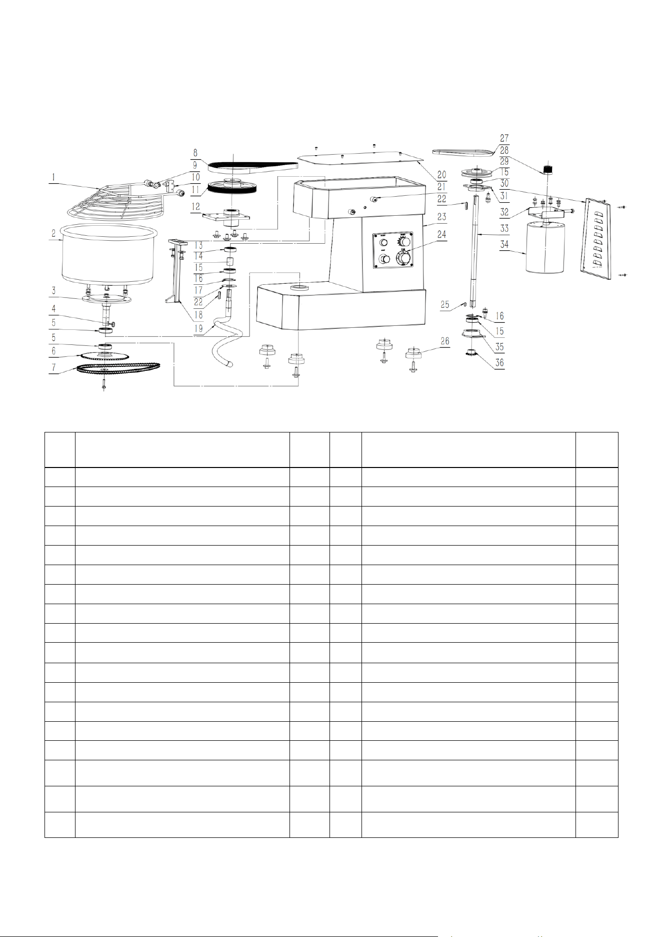
LB40/50 machine description
If you need to replace the parts, you can use the parts list below to let us know your requirements.
NO.
Name of part
Qty
NO.
Name of part
Qty
1
Net cover
1
19
Screw hook
1
2
Face barrels(40L/50L)
1
20
Upper cover plate
1
3
Lower axis
1
21
Eccentric shaft sleeve
3
4
10*20 Square key
1
22
8*32 Square key
2
5
Grooved ball bearing (6207)
2
23
Housing
1
6
Output sprocket
1
24
Control panel
1
7
Chain (43/45section)
1
25
8*16 Square key
1
8
Multiple V-belt (10R)
1
26
Rubber foot
4
9
Fixed bushing
1
27
Deltoid
1
10
Shift switch
1
28
V-belt (10R)
1
11
Multiple V-belt pulley (10R)
1
29
V-belt pulley
1
12
Upper bearing seat
1
30
Rear cover plate
1
13
Grooved ball bearing (62/22)
1
31
Upper bearing seat
1
14
Bearing spacer
1
32
Motor adjusting base
1
15
Deep groove ball bearing (6205/1205)
3
33
Central axis
1
16
Circlip (52 section)
2
34
Electric machine (1.8/2.2KW)
1
17
Oil seal cover
1
35
Lower bearing seat
1
18
Center pole
1
36
Drive pinion
1
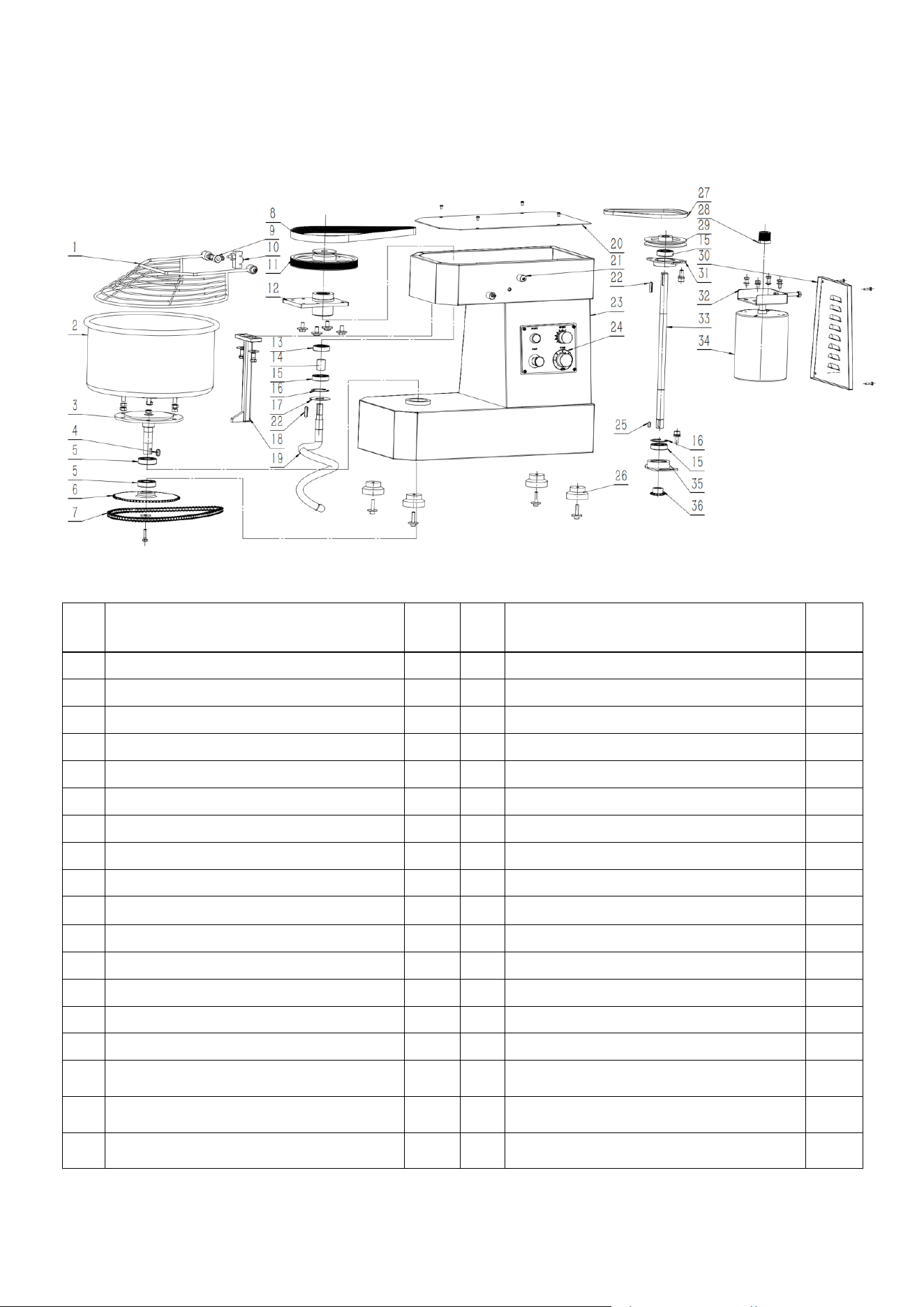
LB60 machine description
If you need to replace the parts, you can use the parts list below to let us know your requirements.
NO.
Name of part
Qty
NO.
Name of part
Qty
1
Net cover
1
19
Screw hook
1
2
Face barrels (60L)
1
20
Upper cover plate
1
3
Lower axis
1
21
Eccentric shaft sleeve
3
4
10*20 Square key
1
22
8*32 Square key
2
5
Grooved ball bearing (6207)
2
23
Housing
1
6
Output sprocket
1
24
Control panel
1
7
Chain (45section)
1
25
8*16 Square key
1
8
Multiple V-belt (12R)
1
26
Rubber foot
4
9
Fixed bushing
1
27
Deltoid
1
10
Shift switch
1
28
V-belt (12R)
1
11
Multiple V-belt pulley (12R)
1
29
V-belt pulley
1
12
Upper bearing seat
1
30
Rear cover plate
1
13
Grooved ball bearing (6205)
1
31
Upper bearing seat
1
14
Bearing spacer
1
32
Motor adjusting base
1
15
Deep groove ball bearing (6205/1205)
3
33
Central axis
1
16
Circlip (52 section)
2
34
Electric machine (2.5KW)
1
17
Oil seal cover
1
35
Lower bearing seat
1
18
Center pole
1
36
Drive pinion
1

Eurodib Corp.
Postal address:
334 Cornelia St. #272
Plattsburgh, NY, 12901
USA
Office:
401 Penbrooke Dr., Suite 3R
Penfield, NY, 14526
USA
J
4
B
2
X
Eurodib Inc.
120 de la Barre
Boucherville
QC J4B 2X7
CANADA
Tel: 1-888-956-6866
www.eurodib.com
customerservi[email protected]
J
4
B
2