user manual
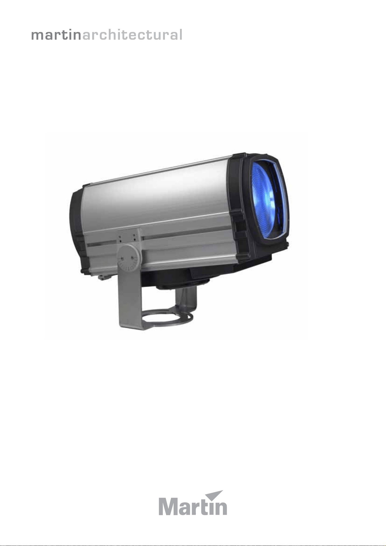
Exterior 1200 Wash
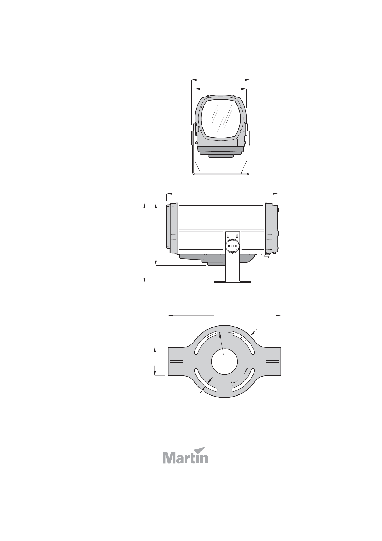
Dimensions
448
392
620
485
860
13
432
110
Ø247
55°
Ø280
Luminaire
Mounting yoke base
© 2006 Martin Professional A/S. All rights reserved. No part of this manual may be reproduced, in any form or by any means, without
permission in writing from Martin Professional A/S. Information subject to change without notice. Martin Professional A/S and all
affiliated companies disclaim liability for any injury, damage, direct or indirect loss, consequential or economic loss or any other loss
occasioned by the use of, inability to use or reliance on the information contained in this manual. Please check with your Martin
Architectural supplier that you have the latest product information before installing or servicing this product.
P/N 35000177 Rev.
C
Measurements are in millimeters

3
Section 1. Safety
4 Exterior 1200 Wash user manual
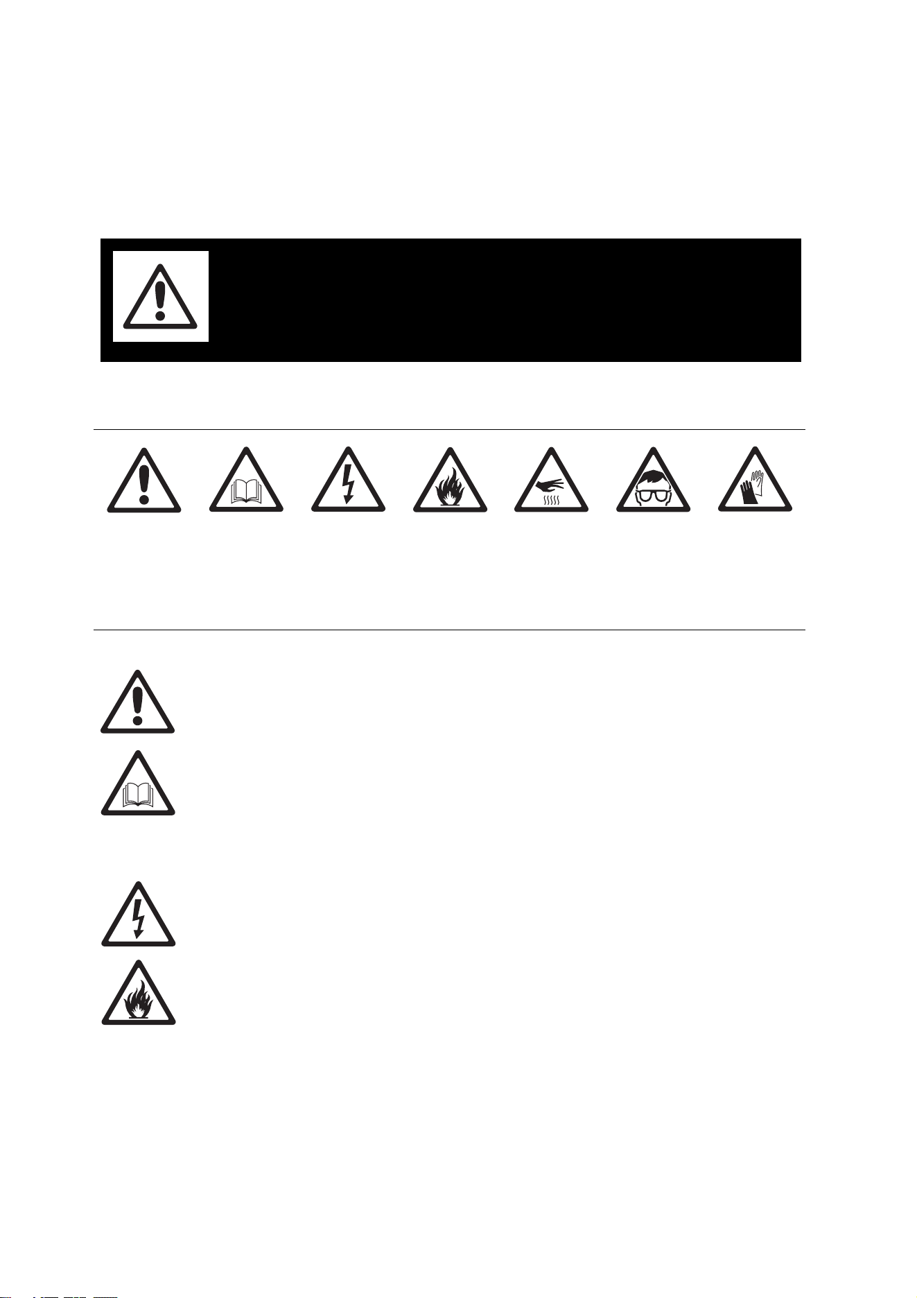
1.1 Safety information
The following symbols are used to identify important safety information on the product and
in this manual:
DANGER! This product is for professional use only. It is not for household
use. If safety precautions are not followed, it presents risks of injury due to
electric shock, heat and ultraviolet radiation burns, lamp explosion, falls,
high-intensity light, and fire.
Read this manual before installing, powering, operating or servicing the
luminaire. Follow the safety precautions listed below, and observe all
warnings in this manual and on the luminaire. Use the luminaire only as
described in this manual and in accordance with local laws and regulations.
Refer any operation not described in this manual to a qualified technician.
Electrical safety
• Do not use the luminaire if any cable, component or cover is damaged, cracked or
deformed.
• Switch the lamp off, allow the luminaire to cool with fans running for 20 minutes, then
isolate it from AC power and lock out power before removing or installing the lamp,
fuses, or any part.
• Ensure that the luminaire is correctly configured for the local AC power voltage as
described in this manual before applying power for the first time.
• Always ground (earth) the luminaire electrically.
• Use only a source of AC power that complies with local building and electrical codes and
has both overload and ground fault (earth fault) protection.
WARNING!
Read the safety precautions in this section
before installing, powering, operating or
servicing this product.
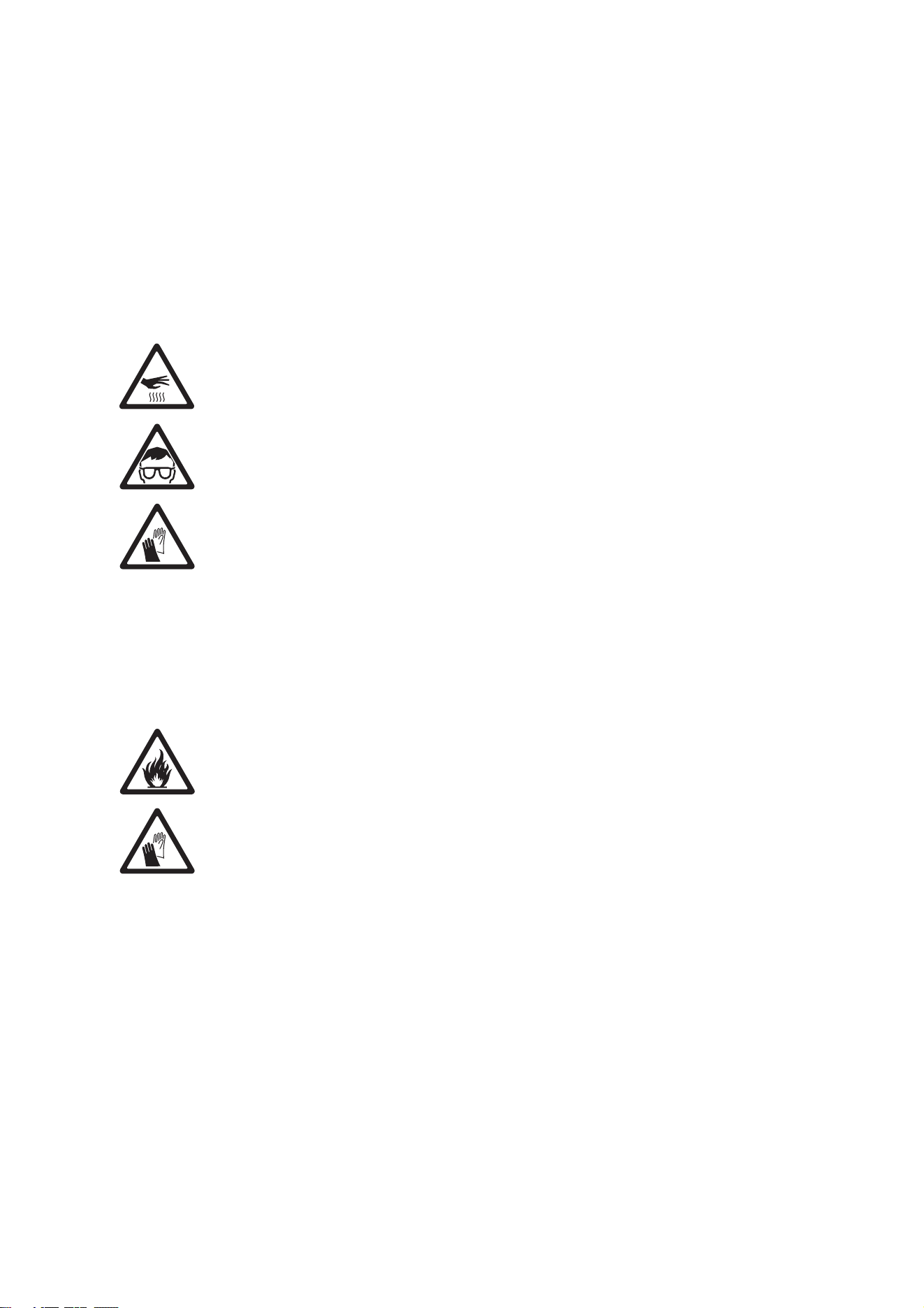
DANGER!
Safety hazard.
Risk of severe
injury or death.
DANGER!
Refer to user
manual for
important
safety
information.
DANGER!
Hazardous
voltage. Risk of
lethal or severe
electric shock.
DANGER!
Fire hazard.
Warning!
Burn hazard.
Hot surface. Do
not touch.
Warning!
Risk of eye
injury. Safety
glasses must
be worn.
Warning!
Risk of hand
injury. Safety
gloves must be
worn.
Safety information 5
• Ensure that the AC power distribution system includes a means of isolating all installed
devices from power and locking out power during service.
• Ensure that all components in the AC power distribution circuits (cables, junction boxes,
etc.) are protected from water and airborne particles to IP67 or higher, are suitably
dimensioned for the current and power requirements of the devices installed, and are of
suitable type for the location (including water, pollution, temperature and UV resistance).
• Do not expose any part of the luminaire to a high-pressure water jet.
• Do not expose the heat exchanger to water projections.
• Do not immerse the luminaire in water or any other fluid, or install it in a location where
flooding may occur.
• Refer all service not described in this manual to a Martin service technician.
Lamp safety
• Do not operate the luminaire with missing or damaged covers, shields, lenses or
ultraviolet screens: an unshielded discharge lamp emits UV radiation that can cause
burns and eye damage.
• Do not stare directly into the light output. Never look at an exposed lamp while it is lit.
• A hot discharge lamp is under pressure and can explode without warning. Allow the
luminaire to cool for at least 20 minutes and protect yourself with safety glasses and
safety gloves before replacing the lamp or servicing the luminaire internals.
• If the quartz envelope of a discharge lamp is broken, the lamp releases a small quantity
of mercury and other toxic gases. If a discharge lamp explodes in a confined area,
evacuate the area and ventilate it thoroughly. Wear non-porous safety gloves when
handling a broken discharge lamp. Treat broken or used discharge lamps and used
safety gloves as hazardous waste and send to a specialist for disposal.
• Replace the lamp if it becomes visually deformed, damaged or in any way defective
• Replace the lamp at the latest when it reaches the limit of its average life as specified in
this manual or by the lamp manufacturer.
• Install only an approved lamp.
Protection from burns and fire
• Do not operate the luminaire if the ambient temperature (T
a
) exceeds 45° C (113° F).
• The exterior of the luminaire becomes hot, up to 90° C (194° F) during normal operation.
Ensure that accidental physical contact with an installed luminaire is impossible.
• Keep flammable materials well away from the luminaire.
• Keep all combustible materials (for example fabric, wood, paper) at least 1 m (40 in.)
away from the luminaire.
• Do not illuminate surfaces within 1 m (40 in.) of the luminaire.
• Allow the luminaire to cool for 20 minutes before servicing.
• Do not attempt to bypass thermostatic switches or fuses. Replace defective fuses with
ones of the specified type and rating only.
• Do not modify the luminaire in any way not described in this manual.
• Install only genuine Martin parts and approved lamps.
• Provide a minimum clearance of 135 mm (5.5 in.) and ensure unobstructed airflow
around the air vents in the heat exchanger cowling.
• Provide a minimum clearance of 150 mm (6 in.) between the top of the luminaire and
any part of a building above the luminaire.
• Provide a minimum clearance of 400 mm (16 in.) between the center of the luminaire
and any part of a building to the side of the luminaire.

6 Exterior 1200 Wash user manual
• Provide a minimum center-to-center distance of 800 mm (31.5 in.) between Exterior
1200 Wash luminaires.
• Install the luminaire outdoors or in a well ventilated area.
• Do not place filters or other materials over the lens. Use only Martin approved
accessories to mask or modify the light beam.
Preventing injury due to falls and while lifting
• Ensure that all external covers, components and installation fittings are securely
fastened.
• The luminaire weighs 68 kg (150 lbs.). At least two people are required to lift, move and
adjust it. Do not attempt to lift the luminaire or adjust the beam angle alone.
• Block access below the work area and work from a stable platform whenever installing,
servicing or moving the luminaire.
• Ensure that all supporting structures, surfaces, fasteners and lifting equipment can bear
the weight of all the devices they are intended to support plus an adequate safety
margin, and that they conform to local building and safety regulations.
• Use a sufficient number of fasteners with sufficient corrosion resistance, dimensions and
strength to mount the luminaire safely. Any nuts used must be self-locking. The washers
supplied with the luminaire must be installed directly under the fasteners’ heads when
anchoring the yoke base to the installation surface.
• The four eyebolts supplied are for lifting purposes during installation or service only. Do
not expose them to undue stress while lifting, by allowing the luminaire to drop and then
catching it again, for example. Do not use the eyebolts for safety attachment.

Safety information 7
Contents
Section 1. Safety . . . . . . . . . . . . . . . . . . . . . . . . . . . . . . . . . . . . . . . . . . . . . . . . . . . . . . . 3
1.1 Safety information . . . . . . . . . . . . . . . . . . . . . . . . . . . . . . . . . . . . . . . . . . . . . 4
Section 2. Introduction . . . . . . . . . . . . . . . . . . . . . . . . . . . . . . . . . . . . . . . . . . . . . . . . . 9
2.1 About this manual . . . . . . . . . . . . . . . . . . . . . . . . . . . . . . . . . . . . . . . . . . . . 10
2.2 Introduction to the Exterior 1200 Wash . . . . . . . . . . . . . . . . . . . . . . . . . . . 11
Section 3. Installation . . . . . . . . . . . . . . . . . . . . . . . . . . . . . . . . . . . . . . . . . . . . . . . . . 13
3.1 Physical installation . . . . . . . . . . . . . . . . . . . . . . . . . . . . . . . . . . . . . . . . . . . 14
3.1.1 Unpacking. . . . . . . . . . . . . . . . . . . . . . . . . . . . . . . . . . . . . . . . . . . . 14
3.1.2 Location and mounting . . . . . . . . . . . . . . . . . . . . . . . . . . . . . . . . . . 15
3.1.3 Power and DMX data cable layout . . . . . . . . . . . . . . . . . . . . . . . . . 17
3.1.4 Connections compartment access . . . . . . . . . . . . . . . . . . . . . . . . . 18
3.2 Installing AC power . . . . . . . . . . . . . . . . . . . . . . . . . . . . . . . . . . . . . . . . . . . 19
3.2.1 Configuring for local AC power. . . . . . . . . . . . . . . . . . . . . . . . . . . . 19
3.2.2 Connecting to AC power. . . . . . . . . . . . . . . . . . . . . . . . . . . . . . . . . 20
3.3 Installing a data link . . . . . . . . . . . . . . . . . . . . . . . . . . . . . . . . . . . . . . . . . . . 22
3.3.1 Planning the data link . . . . . . . . . . . . . . . . . . . . . . . . . . . . . . . . . . . 22
3.3.2 Building the data link. . . . . . . . . . . . . . . . . . . . . . . . . . . . . . . . . . . . 22
Section 4. General . . . . . . . . . . . . . . . . . . . . . . . . . . . . . . . . . . . . . . . . . . . . . . . . . . . . 25
4.1 General . . . . . . . . . . . . . . . . . . . . . . . . . . . . . . . . . . . . . . . . . . . . . . . . . . . . . 26
4.1.1 Powering on . . . . . . . . . . . . . . . . . . . . . . . . . . . . . . . . . . . . . . . . . . 26
4.1.2 Powering off . . . . . . . . . . . . . . . . . . . . . . . . . . . . . . . . . . . . . . . . . . 26
4.1.3 Lamp operation. . . . . . . . . . . . . . . . . . . . . . . . . . . . . . . . . . . . . . . . 26
4.1.4 ‘Exercise Program’ at lamp off . . . . . . . . . . . . . . . . . . . . . . . . . . . . 27
4.1.5 Onboard control panel . . . . . . . . . . . . . . . . . . . . . . . . . . . . . . . . . . 27
4.1.6 Cooling fans . . . . . . . . . . . . . . . . . . . . . . . . . . . . . . . . . . . . . . . . . . 28
4.1.7 Operating in hot environments . . . . . . . . . . . . . . . . . . . . . . . . . . . . 28
4.1.8 Operating in cold environments . . . . . . . . . . . . . . . . . . . . . . . . . . . 29
4.1.9 LEDs and operating status . . . . . . . . . . . . . . . . . . . . . . . . . . . . . . . 29
Section 5. Settings and configuration. . . . . . . . . . . . . . . . . . . . . . . . . . . . . . . . . . . 31
5.1 Luminaire settings . . . . . . . . . . . . . . . . . . . . . . . . . . . . . . . . . . . . . . . . . . . . 32
5.1.1 Setting up a luminaire with a PC and MUM . . . . . . . . . . . . . . . . . . 33
5.1.2 Setting up a luminaire with an MP-2. . . . . . . . . . . . . . . . . . . . . . . . 36
5.1.3 Setting up a luminaire with the onboard control panel . . . . . . . . . . 37
Section 6: Stand-alone operation . . . . . . . . . . . . . . . . . . . . . . . . . . . . . . . . . . . . . . . 39
6.1 Stand-alone programming: general . . . . . . . . . . . . . . . . . . . . . . . . . . . . . . 40
6.1.1 Introduction. . . . . . . . . . . . . . . . . . . . . . . . . . . . . . . . . . . . . . . . . . . 40
6.1.2 Synchronized operation with multiple luminaires . . . . . . . . . . . . . . 40
6.1.3 Stand-alone programming methods . . . . . . . . . . . . . . . . . . . . . . . . 42
6.2 Stand-alone programming with a PC and MUM. . . . . . . . . . . . . . . . . . . . . 43
6.2.1 Connecting . . . . . . . . . . . . . . . . . . . . . . . . . . . . . . . . . . . . . . . . . . . 43
6.2.2 Stand-alone settings. . . . . . . . . . . . . . . . . . . . . . . . . . . . . . . . . . . . 44
6.2.3 Programming effects in scenes . . . . . . . . . . . . . . . . . . . . . . . . . . . 45
6.2.4 Programming the same stand-alone show on multiple luminaires . 47

8 Exterior 1200 Wash user manual
6.3 Stand-alone operation . . . . . . . . . . . . . . . . . . . . . . . . . . . . . . . . . . . . . . . . . 48
6.3.1 Starting show playback automatically at luminaire power-on . . . . . 48
6.3.2 DMX controller override during stand-alone show playback. . . . . . 48
Section 7. DMX control . . . . . . . . . . . . . . . . . . . . . . . . . . . . . . . . . . . . . . . . . . . . . . . . 49
7.1 Preparing for DMX control. . . . . . . . . . . . . . . . . . . . . . . . . . . . . . . . . . . . . . 50
7.1.1 Setting DMX addresses . . . . . . . . . . . . . . . . . . . . . . . . . . . . . . . . . 50
7.1.2 DMX Lamp Off option . . . . . . . . . . . . . . . . . . . . . . . . . . . . . . . . . . . 51
7.1.3 DMX Reset option. . . . . . . . . . . . . . . . . . . . . . . . . . . . . . . . . . . . . . 51
7.2 DMX controller operation. . . . . . . . . . . . . . . . . . . . . . . . . . . . . . . . . . . . . . . 52
7.2.1 Effect operation. . . . . . . . . . . . . . . . . . . . . . . . . . . . . . . . . . . . . . . . 52
7.2.2 Lamp. . . . . . . . . . . . . . . . . . . . . . . . . . . . . . . . . . . . . . . . . . . . . . . . 52
7.2.3 Color . . . . . . . . . . . . . . . . . . . . . . . . . . . . . . . . . . . . . . . . . . . . . . . . 53
7.2.4 Dimmer . . . . . . . . . . . . . . . . . . . . . . . . . . . . . . . . . . . . . . . . . . . . . . 53
7.2.5 Zoom. . . . . . . . . . . . . . . . . . . . . . . . . . . . . . . . . . . . . . . . . . . . . . . . 53
7.2.6 Effects speed (tracking and vector control) . . . . . . . . . . . . . . . . . . 53
Section 8. Service and accessories . . . . . . . . . . . . . . . . . . . . . . . . . . . . . . . . . . . . . 55
8.1 Service: general . . . . . . . . . . . . . . . . . . . . . . . . . . . . . . . . . . . . . . . . . . . . . . 56
8.2 Beam adjustment . . . . . . . . . . . . . . . . . . . . . . . . . . . . . . . . . . . . . . . . . . . . . 56
8.3 Cleaning. . . . . . . . . . . . . . . . . . . . . . . . . . . . . . . . . . . . . . . . . . . . . . . . . . . . . 57
8.3.1 Cleaning the heat exchanger . . . . . . . . . . . . . . . . . . . . . . . . . . . . . 57
8.3.2 Cleaning the housing and front glass . . . . . . . . . . . . . . . . . . . . . . . 58
8.4 Seals and cable glands . . . . . . . . . . . . . . . . . . . . . . . . . . . . . . . . . . . . . . . . 58
8.4.1 Seals. . . . . . . . . . . . . . . . . . . . . . . . . . . . . . . . . . . . . . . . . . . . . . . . 58
8.4.2 Cable glands. . . . . . . . . . . . . . . . . . . . . . . . . . . . . . . . . . . . . . . . . . 59
8.4.3 Torque settings. . . . . . . . . . . . . . . . . . . . . . . . . . . . . . . . . . . . . . . . 60
8.5 Lamp maintenance . . . . . . . . . . . . . . . . . . . . . . . . . . . . . . . . . . . . . . . . . . . . 61
8.5.1 Approved lamp . . . . . . . . . . . . . . . . . . . . . . . . . . . . . . . . . . . . . . . . 61
8.5.2 Lamp life and monitoring lamp hours . . . . . . . . . . . . . . . . . . . . . . . 61
8.5.3 Installing the lamp. . . . . . . . . . . . . . . . . . . . . . . . . . . . . . . . . . . . . . 62
8.6 Installing color filters . . . . . . . . . . . . . . . . . . . . . . . . . . . . . . . . . . . . . . . . . . 64
8.7 Replacing fuses . . . . . . . . . . . . . . . . . . . . . . . . . . . . . . . . . . . . . . . . . . . . . . 66
8.8 Software-based service functions . . . . . . . . . . . . . . . . . . . . . . . . . . . . . . . 67
8.8.1 Adjustment and monitoring. . . . . . . . . . . . . . . . . . . . . . . . . . . . . . . 67
8.8.2 Restoring factory defaults. . . . . . . . . . . . . . . . . . . . . . . . . . . . . . . . 67
8.8.3 Software updates . . . . . . . . . . . . . . . . . . . . . . . . . . . . . . . . . . . . . . 68
8.9 Troubleshooting . . . . . . . . . . . . . . . . . . . . . . . . . . . . . . . . . . . . . . . . . . . . . . 69
8.10 Accessories. . . . . . . . . . . . . . . . . . . . . . . . . . . . . . . . . . . . . . . . . . . . . . . . . 70
Section 9. Reference . . . . . . . . . . . . . . . . . . . . . . . . . . . . . . . . . . . . . . . . . . . . . . . . . . 71
9.1 Connections compartment . . . . . . . . . . . . . . . . . . . . . . . . . . . . . . . . . . . . . 72
9.2 LED status messages. . . . . . . . . . . . . . . . . . . . . . . . . . . . . . . . . . . . . . . . . . 73
9.3 Onboard control panel menus. . . . . . . . . . . . . . . . . . . . . . . . . . . . . . . . . . . 74
9.4 MP-2 control menus . . . . . . . . . . . . . . . . . . . . . . . . . . . . . . . . . . . . . . . . . . . 75
9.5 DMX protocol . . . . . . . . . . . . . . . . . . . . . . . . . . . . . . . . . . . . . . . . . . . . . . . . 77
Exterior 1200 Wash specifications. . . . . . . . . . . . . . . . . . . . . . . . . . . . . . . . . . . . . . 78

Section 2. Introduction

10 Exterior 1200 Wash user manual
2.1 About this manual
This user manual is organized into sections. Depending on whether you are installing,
programming or operating the product, and depending on the method and hardware used
to configure and operate the product, you probably do not need to read every section.
The outline below should help you see which sections are relevant to you:
Section Contents Who needs to read it
Section 1. Safety, page 3 Vital safety information All
Section 2. Introduction, page 9 Brief overview of the product All
Section 3. Installation, page 13 Instructions for:
Physical installation
Installing AC power
Installing a data/DMX link
Installer (physical
installer, installation
electrician, data/DMX
system installer)
Section 4. General, page 25 Main features and functions as well as
programming and operating principles
All involved in
programming and
operating
Section 5. Settings and
configuration, page 31
Instructions for carrying out basic
configuration
All involved in
programming and
operating
Section 6: Stand-alone
operation, page 39
Instructions for setting up and running
stand-alone operation
Programmer and
operator, if stand-
alone operation used
Section 7. DMX control, page 49 Instructions for setting up and using
DMX control
Programmer and
operator, if DMX
control used
Section 8. Service and
accessories, page 55
Service, maintenance and adjustment
procedures. Overview of accessories.
Owner, service
technician
Section 9. Reference, page 71 Reference diagrams, charts, etc. All
Exterior 1200 Wash
specifications, page 78
Product specifications All
Table 1: Using this manual

2.2 Introduction to the Exterior 1200
Wash
Thank you for selecting the Exterior 1200 Wash from Martin Architectural. This automated
luminaire combines dynamic architectural lighting effects with extremely bright output in an
aluminum housing designed for permanent outdoor installation. The luminaire uses a Philips
MSD 1200 metal halide discharge lamp with an average lamp life of 3000 hours. An air/air heat
exchanger system ensures effective cooling.
All models feature independently variable 0 - 100% cyan, magenta and yellow (CMY) color
mixing as well as a color wheel with red, green and blue dichroic color filters and a 5500 to
3400 K dichroic color temperature correction (CTC) filter installed as standard. All models
feature full-range continuous dimming.
The beam angles of Narrow and Medium models can be controlled remotely using a motorized
zoom feature.
The Exterior 1200 Wash is available in the following optical configurations (figures are for one-
tenth peak beam angles, ranges indicate minimum and maximum zoom limits):
• Narrow: 14° - 31°
• Medium: 20° - 50°
• Wide: 60°
• Very Wide: 97°
All dynamic effects can be controlled using industry-standard DMX intelligent lighting control
technology or run independent or synchronized stand-alone light shows that do not require
external control. Stand-alone light show start and stop times can either be programmed using
the luminaire’s onboard clock or triggered by ambient light level within programmed times.
Snoot and barndoors kits are available as accessories for all models. When mounted on the
front of a luminaire, snoots and barndoors allow control of both beam shape and glare. A beam
shaper lens available as an accessory for Narrow and Medium models, optically modifies
output to give an elliptical beam.
A permanent CTC filter is also available as an accessory. The permanent filter allows precise
color matching with other luminaires with different lamps.
This advanced product requires regular service and maintenance in order to ensure optimum
operation and protect the investment it represents. Installation, on-site service and
maintenance can be provided worldwide by the Martin Global Service organization and its
authorized agents. Choosing a Martin service contract gives owners access to Martin’s
expertise and product knowledge in a partnership that will ensure the highest level of
performance throughout the product’s lifetime.

12 Exterior 1200 Wash user manual

Introduction to the Exterior 1200 Wash 13
Section 3. Installation

14 Exterior 1200 Wash user manual
3.1 Physical installation
DANGER! Read "Safety information" on page 4 before installing the Exterior
1200 Wash.
Warning! The safety and suitability of lifting equipment, installation
location, anchoring method, mounting hardware and electrical installation
is the responsibility of the installer. All local safety regulations and legal
requirements must be observed when installing and connecting the Exterior
1200 Wash. Installation must be carried out by qualified professionals only.
Contact your Martin Architectural supplier for assistance if you have any questions about
how to install this product safely.
3.1.1 Unpacking
The Exterior 1200 Wash is supplied with the following items:
• Mounting yoke.
• Cable glands for power and control cable entry.
• Blanking plugs (installed) for sealing unused cable entry holes.
• User manual.
See Figure 1. The mounting yoke is folded back for shipment. When the luminaire has
been unpacked:
1. Supporting the luminaire’s weight, rest it on its top (the opposite surface to the heat
exchanger) and use an Allen key to loosen the yoke clamp locking screws (A) and tilt
lock screws (B) on each side of the yoke.
2. Fold the yoke around to the bottom of the fixture (normally the side with the heat
exchanger), and slide the yoke forwards until the edge of the yoke lines up with the
mark (arrowed) on the label on the side of the luminaire. In this position, the edge of
the yoke is 300 mm (12 in.) from the end of the luminaire and the luminaire’s weight is
balanced in the yoke.
3. Tighten the yoke clamp locking screws and tilt lock screws to approximately 16 Nm
(11.8 ft.-lbs.).
300mm
12”
Mounting yoke
Heat exchanger
Figure 1: Mounting yoke adjustment
AA
B B
6mm
Physical installation 15
3.1.2 Location and mounting
DANGER! Read "Safety information" on page 4 before attempting to install
this product.
Installation will probably be easiest if the lamp is installed before installing the luminaire
(see "8.5.3: Installing the lamp" on page 62).
Lifting
DANGER! Use only the lifting eyebolts provided to lift the luminaire.
Eyebolts must be securely installed with washers at all four corners of the
luminaire as illustrated below.
See Figure 2. The Exterior 1200 Wash is supplied with four eyebolts for lifting purposes
during installation or service. Do not use any other method to lift the luminaire. The
eyebolts screw into blocks in the yoke slider channels on each side of the fixture. Use the
supplied washers to avoid damage to the luminaire housing. Make sure that eyebolts are
firmly screwed in and will not slide in the channels before attempting to lift the luminaire.
Do not expose the eyebolts to undue stress while lifting, by allowing the luminaire to drop
and then catching it again, for example. Do not use the eyebolts for safety attachment.
Location and orientation
DANGER! The Exterior 1200 Wash mounting yoke base must be securely
anchored to a suitable flat surface. Ensure that the supporting structure can
bear the weight of all installed devices plus an adequate safety margin.
Consult a qualified engineer to determine a suitable anchoring method and to verify that
the structure can safely bear the luminaire’s weight.
Figure 2: Lifting eyebolts
16 Exterior 1200 Wash user manual
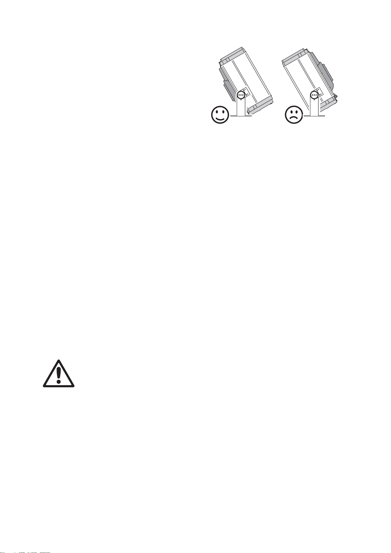
The Exterior 1200 Wash is rated UL Wet
Location. When choosing a location for
installation, consider that the main
housing has an ingress protection (IP)
rating of 65, but that the heat exchanger
unit must be protected from rain or direct
water projections that might fill the heat
exchanger with water and cause
overheating. The luminaire may
therefore be installed in any orientation,
but it must be positioned so that the heat
exchanger is on the lower side of the
luminaire (see Figure 3). If necessary,
loosen the yoke tilt lock screws (B in
Figure 1) and reposition the yoke.
Allow for service access to the front and rear of the luminaire.
The Exterior 1200 Wash can be installed outdoors but:
• Do not expose it to high-pressure water jets from any direction
• Do not immerse it in water (or any other fluid)
• Do not install it in a location where flooding may occur.
Ensure sufficient drainage to cope with the heaviest rainfall. Make sure that water can
drain away from the installation area at least as fast as it can enter it.
The Exterior 1200 Wash requires free and unobstructed airflow around the heat
exchanger to ensure adequate cooling:
• Do not bury the luminaire or locate it in an unventilated space
• Allow 135 mm (5.5 in.) free space around the heat exchanger
• Make sure that leaves, litter or other debris cannot be sucked into the heat exchanger,
as blockages may cause overheating and result in damage that is not covered by the
product warranty.
Install the luminaire at least 1 m (40 in.) away from the surface to be illuminated and any
combustible materials (wood, paper, etc.) and well away from any flammable materials.
The aluminum housing reaches temperatures up to 90° C (194° F). Restrict public access
or locate the luminaire so that it cannot accidentally be touched.
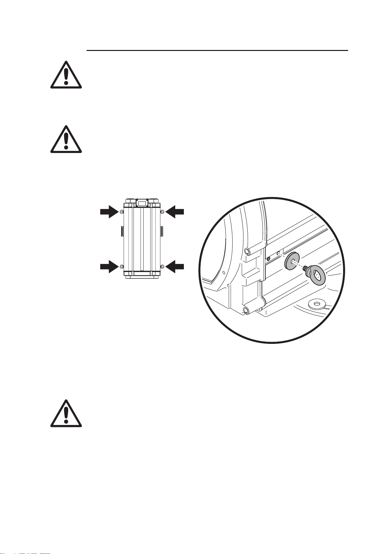
Mounting fasteners
DANGER! All fasteners used to mount the Exterior 1200 Wash must be
corrosion-resistant and strong enough to mount the luminaire safely.
The mounting yoke allows the luminaire to be manually panned (i.e. rotated horizontally)
and tilted for beam aiming adjustment. The yoke base must be safely anchored to a
horizontal surface. The number and type of fasteners used will depend on the installation,
but use at least four high-strength corrosion-resistant fasteners (recommended minimum
properties: A4-70 grade according to ISO 3506 or grade 8.8 according to according to ISO
898-1) evenly distributed around the yoke base. Any nuts used must be self-locking. The
washers supplied with the luminaire must be installed between the head of each fastener
and the yoke base.
To mount the luminaire, evenly space 12 mm (1/2 inch) thread diameter bolts at 90°
intervals on a 123.5 mm (4.86 inch) radius from the center of the mounting location, so
Figure 3:
Heat exchanger position
Physical installation 17
that one bolt passes through each curved slot in the yoke base (see Figure 4). If additional
bolts are required to mount the luminaire safely, pan adjustment range will be reduced.
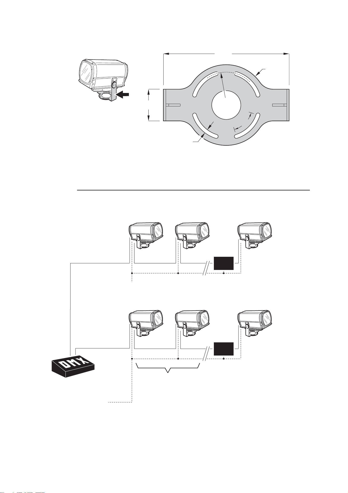
3.1.3 Power and DMX data cable layout
Figure 5 gives an overview of a suitable cable layout. The dotted lines represent AC
power circuits. The solid lines represent the data link.
13
432
110
Ø247
55°
Ø280
Figure 4: Mounting yoke attachment points
Figure 5: Schematic cable layout diagram
OPTO-
SPLITTER
Power
230V AC
50 Hz
Power
230V AC
50 Hz
50 Hz
Max. 32 luminaires
or 500m. before
opto-splitter
is required.
OPTO-
SPLITTER
DMX
Universe #1
DMX
Universe #2
Universe #2
AC power
OPTO-
SPLITTER
Power
230V AC
50 Hz
50 Hz
Power
230V AC
50 Hz
Max. 32 luminaires
or 500m. before
opto-splitter
is required.
Max. 32 luminaires
or
500m. before
opto-splitter
is
required.
OPTO-
SPLITTER
DMX
Universe #1
Universe #1
DMX
Universe #2
AC power
18 Exterior 1200 Wash user manual
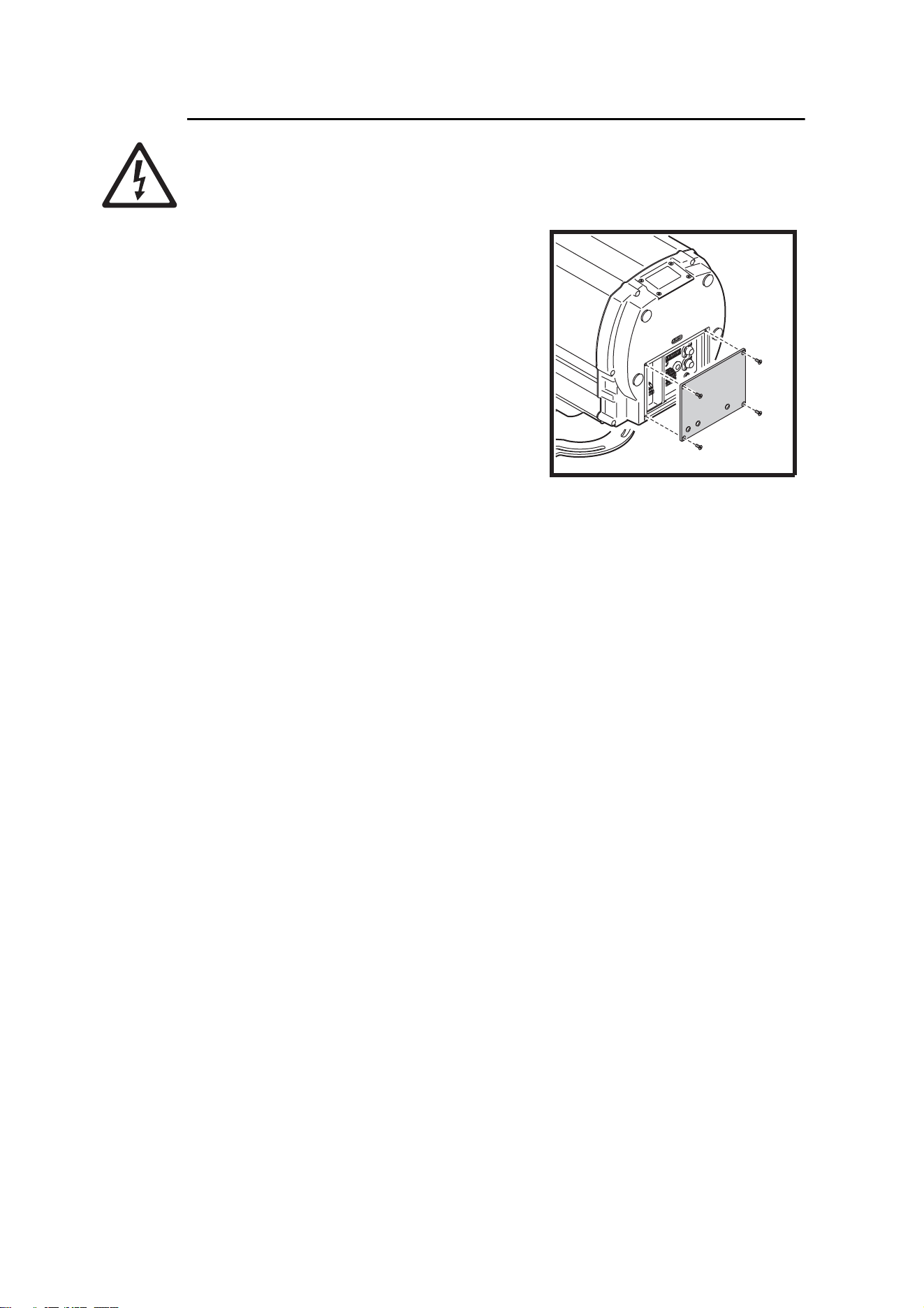
3.1.4 Connections compartment access
DANGER! Fuseholders remain live even if the MAINS switch is set to off. Cut
power to the luminaire before changing a fuse.
To gain access to the connections compartment:
1. If the luminaire has been in use, allow it to
cool completely.
2. If you intend to open a main fuseholder, cut
AC power to the luminaire and ensure that
power cannot be reapplied accidentally by
locking it out.
3. See Figure 6. Loosen the screws in the rear
cover plate and carefully remove the plate
and seal.
4. If you intend to alter any connections, shut
down AC power by setting the MAINS switch
to 0 (off). Before you touch any connectors,
use a tester to check that they are not live.
After access to the connections compartment:
1. Check the condition of the rear cover seal. Replace with a new item if the seal is torn,
cracked or brittle.
2. Hold the rear cover plate and seal firmly against the luminaire housing. Adjust the
sides of the seal so that the seal sticks out a little, just enough so that you can feel the
seal when you run a finger across the joint.
3. Cross-tighten the cover plate screws gradually and evenly to 2 Nm (1.5 ft.-lbs.). At this
torque, the seal will be compressed by about one-third and will be waterproof to IP65.
Figure 6: Connections
compartment cover plate

Installing AC power 19
3.2 Installing AC power
DANGER! Read "Safety information" on page 4 before attempting to install
this product.
Electrical installation must be carried out by qualified professionals only.
For protection from dangerous electric shock, the luminaire must be
grounded (earthed). The AC power distribution system must be fitted with
current overload and ground-fault (earth-fault) circuit breakers as well as a
means to isolate luminaires from power and lock out power during service.
Important! Do not connect the Exterior 1200 Wash to an electrical dimmer
system. Doing so can damage the electronics.
See Figure 5 on page 17 for a schematic diagram of cable layout.
If there is a break or cut at any point in a cable (for example at a connection point), and if
this is exposed to water, moisture can be drawn up the inside of the cable due to the
vacuum effect of temperature fluctuations during operation. Ensure that the luminaire is
protected from the entry of water via the power cable by using IP65-rated connectors or
junction boxes, or by protecting connectors with weatherproof housings.
The Exterior 1200 Wash must be supplied with power via an electrical cable that is
adequately dimensioned for the current requirements and suitable for the installation
environment, particularly with regard to water, pollution, thermal and UV resistance. Use
Hypalon or neoprene rubber-jacket cable rated to 90° C (194° F) minimum. The conductor
size must be 1.5 mm
2
(16 AWG) minimum. Check that all power cables are in perfect
condition.
See "Exterior 1200 Wash specifications" on page 78 for details of fuse rating and typical
current. If you require help in planning or dimensioning the power distribution system,
please contact your Martin Architectural supplier for assistance.
Electrical power installation consists of two steps:
1. Configuring for local AC power
2. Connecting to AC power.
3.2.1 Configuring for local AC power
Before AC power is applied to the Exterior 1200 Wash for the first time (or if the AC power
voltage or frequency changes), the luminaire must be configured to accept the local power
voltage and frequency as described in this section.
The Exterior 1200 Wash can accept the following AC voltages and frequencies:
• 200 V, 208 V, 220 V, 230 V, 240 V, 250 V or 277 V at 50 or 60 Hz.
Operating at the incorrect power setting can result in overheating and damage to the
luminaire and lamp. If your local power voltage differs from the voltage settings listed here
and in the luminaire, contact your Martin Architectural supplier for assistance.
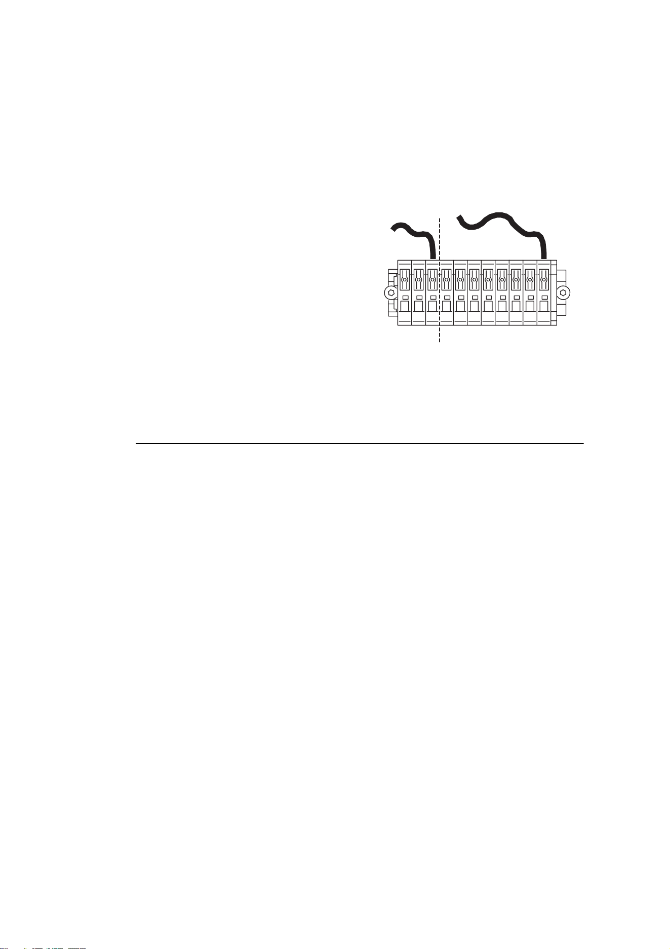
The luminaire must be configured to accept the local AC power frequency and voltage by
connecting the free ends of two jumper leads. The fixed end of each lead sits in an orange
terminal. The free end of each lead must be connected to the appropriate terminal on the
terminal block. Terminals are labelled.
20 Exterior 1200 Wash user manual
The terminals are spring-loaded, and leads can be released by exerting light pressure on
the terminal tab with a flat-head screwdriver.
To configure the luminaire for local AC power:
1. Make sure that the luminaire is isolated from AC power and cannot be accidentally
connected throughout the procedure.
2. Open the connections compartment as described in "3.1.4: Connections compartment
access" on page 18.
3. See Figure 7. Connect the free end of the
frequency setting jumper lead (in the
section marked Hz setting) to the
terminal labeled with the local AC power
frequency.
4. Connect the free end of the voltage
setting jumper lead (in the section marked
Volt setting) to the terminal labeled with
the local AC power voltage.
3.2.2 Connecting to AC power
Power cable must enter the luminaire through an M20 x 1.5 cable gland that accepts 8 -
13 mm (0.32 - 0.5 in.) external diameter cables. A gland is supplied with the luminaire.
The cable gland must be replaced if the power cable diameter is not within this range (see
"8.4.2: Cable glands" on page 59).
One of two cable entry points can be used: either on the cover plate at the rear of the
luminaire, or through the bottom of the connections/power compartment. Using the bottom
of the connections/power compartment is recommended, as cables installed here will not
be disturbed or flexed when the rear cover plate is removed for service. All cable entry/exit
holes that are not used must be sealed with blanking plugs.
1. Make sure that the power cable is isolated from power and that power cannot be
applied accidentally. If the luminaire has been in use, allow it to cool for at least 20
minutes.
2. If necessary, remove the rear cover plate as described in "3.1.4: Connections
compartment access" on page 18
3. Check that the jumper leads are correctly connected to match the local AC power
voltage and frequency (see "3.2.1: Configuring for local AC power" on page 19).
50
60
277
250
240
230
220
208
200
Hz setting Volt setting
Figure 7: Frequency and voltage
settings
Installing AC power 21
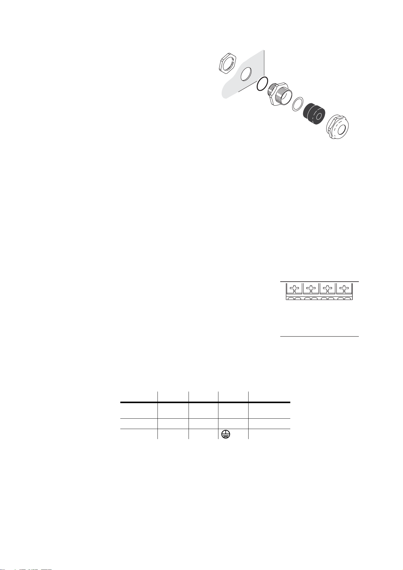
4. See Figure 8. Ensure that there is
a rubber seal B on the locking nut
end of the cable gland C, and
push this end through the hole
provided in the housing so that
the seal faces the outer surface
of the housing.
5. Screw the locking nut A onto the
cable entry from inside the
housing. Prevent the cable entry
from turning, and tighten the
locking nut until the seal makes a
water-resistant seal against the
outer surface of the housing. Do
not over-tighten, as this may
damage the seal or housing.
6. Thread the cable through the
compression nut F, gland E,
washer D, and cable entry C into
the housing.
7. Allow enough cable slack inside the housing to make connections. Prevent the cable
entry from turning and tighten the compression nut sufficiently to make a water-
resistant seal. Do not over-tighten, as this may damage the gland. Check that the
cable is firmly gripped in the rubber gland.
8. See Figure 9. The power terminals block has three
terminals labelled Ground, Neutral, Live 1 and Live 2.
Connect the power cable as follows:
• Connect the power cable’s ground (earth) wire to the
terminal marked Ground.
• If using a single-phase system, connect the power
cable’s neutral wire to the terminal marked Neutral and
connect the power cable’s live wire to the terminal
marked Live 1.
• If using two 120 V phases of a three-phase system to
obtain 208 V, connect one phase to Live 1 and the next
phase to Live 2.
Some common wire color codes are listed in Table 2:
9. If you are also connecting data cables, connect these now, referring to the next section
in this manual. Otherwise replace the rear cover plate as described in "3.1.4:
Connections compartment access" on page 18.
Wire (EU) Wire (US) Pin Marking Screw (US)
brown black live “L”
yellow or
brass
blue white neutral “N” silver
yellow/green green ground green
Table 2: Common wire color codes
Figure 8: Cable gland assembly
A
B
C
D
E
F
A – Locking nut
B – Seal
C – Cable entry
D – Washer
E – Gland
F – Compression nut
50
60
277
250
240
230
220
208
200
Hz Setting Volt Setting
SERVICE
DMX
OUT
DMX
IN
1
++--
23456
Ground
Neutral
Live 1
Live
1
Live 2
Live
2
MAINS
MAIN
FUSE
PCB
Live 2
Fuse
Live 1
Fuse
Figure 9: Power
terminals

22 Exterior 1200 Wash user manual
3.3 Installing a data link
Exterior 1200 Wash luminaires must be connected via a serial data link for DMX controller
operation and for synchronized stand-alone operation of multiple luminaires. The data link
is used to transmit DMX commands or synchronization data.
See Figure 5 on page 17 for a schematic diagram of cable layout.
3.3.1 Planning the data link
The following considerations must be taken into account when planning the data link:
• RS-485 data cable designed for exterior use is required. RS-485 cable has low
capacitance and a characteristic impedance of 85 to 150 Ohms. It is electrically shielded
and has at least 1 twisted pair of conductors. The minimum recommended wire size is
0.25 mm
2
(24 AWG) for runs up to 300 meters (1000 ft.) and 0.32 mm
2
(22 AWG) for
runs up 500 meters (1640 ft).
• The maximum permitted control data cable length before a control signal amplifier is
required is 500 meters (1640 ft.).
• Luminaires must be ‘daisy-chained’, i.e. the data cable must be connected in one single
chain of luminaires.
• Each daisy-chained link may connect a maximum of 32 fixtures.
• An optically isolated amplifier-splitter such as the Martin RS-485 Opto-Splitter (P/N
90758060) must be used to:
- extend a link beyond 500 meters (1640 ft.)
- extend the link to include a further maximum 32 luminaires, or
- branch the link into further single chains, each containing 32 luminaires. The Martin
Opto-Splitter allows a link to be branched into four new chains.
• The last device on each chain must be terminated inside the luminaire using a 120 Ohm,
0.25 Watt resistor (available from your Martin Architectural supplier: P/N 04150308)
connected across the hot and cold data terminals.
• Long parallel runs of AC power and control data cables may cause interference on the
data link and must be avoided. Even if not required by law, separate conduits are
recommended for power and data cables.
• One DMX universe has 512 DMX control channels available. In an installation containing
multiple luminaires that each use 8 DMX channels, for example, one DMX universe will
be required for every 64 luminaires (512 ÷ 8 = 64).
3.3.2 Building the data link
Data cable must enter and exit the luminaire through M16 x 1.5 cable glands that accept
5.5 - 10 mm (0.22 - 0.39 in.) diameter cables. Two glands are supplied with the luminaire.
The glands must be replaced if the data cable external diameter is not within this range
(see "8.4.2: Cable glands" on page 59).
One of two cable entry points can be used: either on the cover plate at the rear of the
luminaire, or through the bottom of the connections/power compartment. Using the bottom
of the connections/power compartment is recommended, as cables installed here will not
be disturbed or flexed when the rear cover plate is removed for service. All cable entry/exit
holes that are not used must be sealed with blanking plugs.
Installing a data link 23
Connection pinouts
XLR connection
XLR connectors are suitable if DMX cable is used for the data link.
XLR pin numbers are normally marked on connectors. Connectors must be wired using
the standard XLR DMX pin-out:
• Pin 1: Cable shield
• Pin 2: DMX Data 1 - (cold)
• Pin 3: DMX Data 1 + (hot)
Pins 4 and 5 on 5-pin XLR connectors are available for Data 2 connections in DMX 512-A
or similar systems. They must be wired as follows:
• Pin 4: DMX Data 2 - (cold)
• Pin 5: DMX Data 2 + (hot)
To avoid ground/earth loop interference, ensure that the DMX cable shield does not come
into contact with the shell or body of XLR connectors.
RJ-45 connection
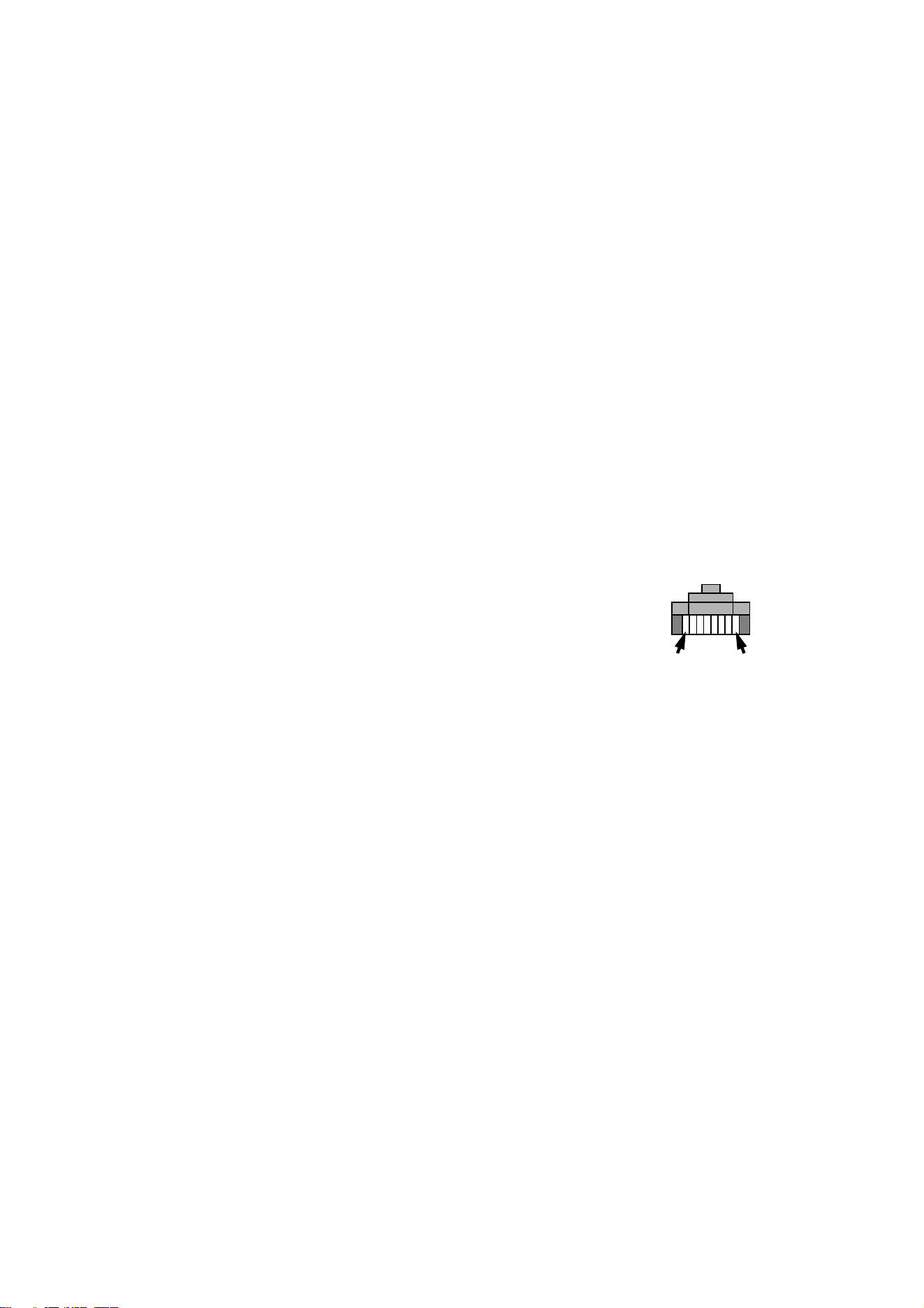
RJ-45 connectors are suitable if CAT 5 cable is used for the data link.
RJ-45 cable connector pins are numbered from the left looking at the face of the
connector with the locking clip on top (see Figure 10). Connectors must be wired using the
standard RJ-45 DMX pin-out:
• Pin 1 (WHITE/orange): DMX hot (+)
• Pin 2 (ORANGE/white): DMX cold (-)
• Pins 7 (WHITE/brown) and 8 (BROWN/white):
Common
Pins 3 and 6 are available for Data 2 connections in
DMX 512-A or similar systems. They must be wired as
follows:
• Pin 3 (WHITE/green): Available for Data 2 hot (+)
• Pin 6 (GREEN/white): Available for Data 2 cold (-)
Pins 4 and 5 are not used in currently available lighting control systems but can be wired
as follows:
• Pin 4 (BLUE/white): Not used
• Pin 5 (WHITE/blue): Not used
Connecting the link
To build a data link:
1. If the luminaire has been in use, allow it to cool for at least 20 minutes.
2. Connect the data cable to a DMX output socket on the DMX controller and route it to
the first luminaire on the link.
3. If the rear cover plate is not already open, remove it as described in "3.1.4:
Connections compartment access" on page 18
4. Pass the data cable into the luminaire using one of the supplied cable glands to ensure
waterproof cable entry. See page 21 for details of installing the cable gland.
Pin 1 Pin 8
Figure 10: RJ-45 cable
connector pins
24 Exterior 1200 Wash user manual
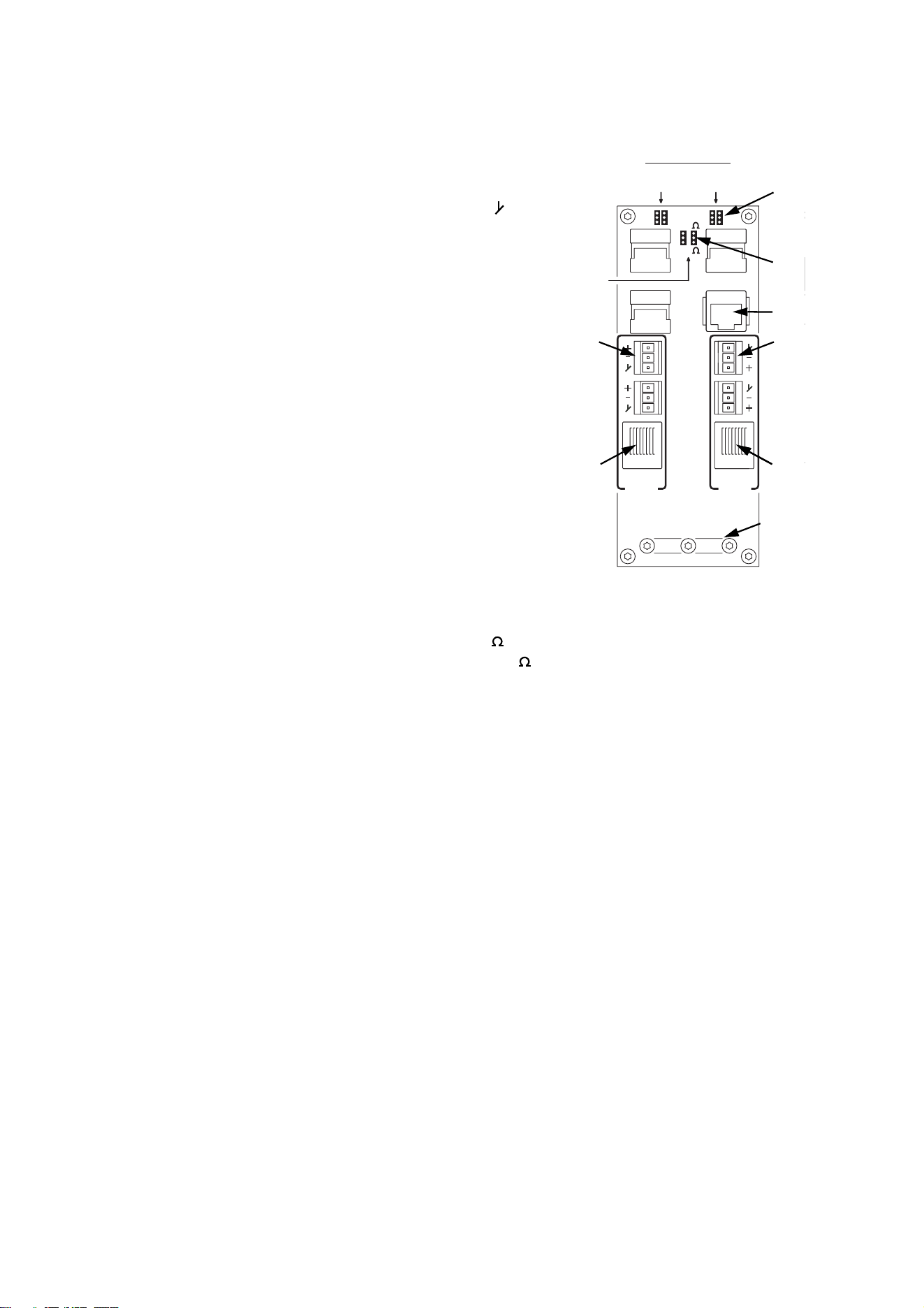
5. Data cable can be connected either via screw terminals on removable connectors or
via RJ-45 connectors.
See Figure 11. Either connect the data cable
to the luminaire’s Data 1 DMX IN screw
terminals (A) as follows:
- Connect shield to the terminal marked
- Connect cold (-) to the terminal marked -
- Connect hot (+) to the terminal marked +
or install an RJ-45 connector on the data
cable respecting the pinout listed under "RJ-
45 connection" on page 23 and insert the
connector into the DMX IN RJ-45 socket (B).
6. Depending on whether the luminaire is the
last one on the link or whether the data link
needs to be continued to another luminaire,
follow one of the following two procedures:
• If the luminaire is the last one on a branch
of the data link, use a pair of long-nosed
pliers to move the DMX termination
jumpers from the Data set 1 pins (C)
marked OFF to the pins marked ON. This
places a resistance across data hot and
cold to terminate the data link. Ensure that
the termination resistance matches the
type of cable used by setting the Cable
impedance jumpers (D) to either 100 if
using CAT5 cable for the data link, or 120 if using standard DMX cable.
• If you need to continue the data link to another luminaire, leave the termination
jumpers at OFF. Pass the data output cable into the luminaire using another cable
gland as described above. Connect to the luminaire’s Data 1 DMX OUT terminals
(E) or RJ-45 DMX OUT socket (F), respecting the same pinouts as for the data input
cable.
7. If using shielded CAT5 cable, connect the cable shield to PCB ground (earth) by
routing the cable under the clamp (G), folding back the cable shield and tightening the
clamp so that it makes good contact with the shield.
8. If the power cable has not already been connected, you can connect it now (see
"3.2.2: Connecting to AC power" on page 20). Otherwise reinstall the rear cover plate
as described in "3.1.4: Connections compartment access" on page 18.
9. Route the data output cable to the data input of the next luminaire, and continue
connecting up to a total of 32 luminaires, output to input, as described above.
Add an optically isolated amplifier/splitter into the link if you intend to add more than 32
luminaires or branch the link.
The Data 2 connections are reserved for future use.
Data
2
Data
1
Termination
Termination
Data
set 2
set 2
Data
set 1
set 1
50
60
277
250
240
230
220
208
200
DMX
OUT
MAINS
MAIN
FUSE
PCB
H
zHz Setting Volt Setting
Live 2
Fuse
Live 1
Fuse
Ground
Neutral
Live 1
Live 2
50
60
277
250
240
230
220
208
200
Hz Setting Volt Setting
Service
RJ45
DMX
IN
Cable
impedance
100
120
Data
2
Data
1
Termination
Termination
Data
set 2
set 2
Data
set 1
set 1
50
60
277
250
240
230
220
208
200
DMX
OUT
MAINS
MAIN
FUSE
PCB
H
zHz Setting Volt Setting
Live 2
Fuse
Live 1
Fuse
Ground
Neutral
Live 1
Live 2
50
60
277
250
240
230
220
208
200
Hz Setting Volt Setting
Service
RJ45
DMX
IN
Cable
impedance
100
120
Figure 11: DMX
connections
A
B
C
D
F
E
G
B
G

Installing a data link 25
Section 4. General

26 Exterior 1200 Wash user manual
4.1 General
DANGER! Read "Safety information" on page 4 before applying power to the
Exterior 1200 Wash.
This section contains general information about the features and functions as well as
basic programming and operating principles of the Exterior 1200 Wash. Read this section
to familiarize yourself with the luminaire before attempting to program or operate it.
Important! Leave the luminaire powered on permanently except during service.
4.1.1 Powering on
When the luminaire is connected to power for the first time, it will start running a factory-
set light show to test the fixture. It will continue to run this test show until a new show is
programmed into it, or until it receives DMX commands.
When the luminaire is powered on in normal use, the luminaire software version appears
in its display, runs an internal test and resets all effects to start positions. It must complete
this reset before it can respond to DMX commands or run a stand-alone show.
4.1.2 Maintaining power and temperature
regulation
Except during service, maintain power to the luminaire permanently even when the lamp
is not lit.
In hot environments, this will allow the cooling system to regulate the luminaire’s internal
temperature at all times. Heat damage resulting from failure to maintain power is not
covered by the product warranty.
In cold environments, the internal heat generated will keep electronics warm and ensure
satisfactory performance at ambient temperatures as low as -20° C (-4° F). Note that if the
temperature inside the luminaire falls below -10° C (14° F), the zoom effect is disabled
until the internal temperature rises above this level again.
4.1.3 Powering off
Important! Switch off the lamp 8 minutes before you cut power to the luminaire.
If the lamp is lit and you wish to cut power (for service, for example), you must first switch
off the lamp via DMX or the onboard control panel and wait at least 8 minutes before you
cut power. This will give cooling fans enough time to reduce the luminaire’s temperature
and avoid heat damage. Damage caused by failure to follow this procedure is not covered
by the product warranty.

General 27
4.1.4 Lamp operation
After being switched off, the lamp must cool for at least 8 minutes before it can be
switched back on. “Lamp On” commands sent within 8 minutes of a “Lamp Off” command
are stored and then attempted again after the time has elapsed.
The lamp can be set to start automatically as soon as power is applied to the luminaire or
started via DMX.
Discharge lamps draw an extra inrush current for a fraction of a second during startup. If a
large number of luminaires start up at the same time, this current can trip circuit breakers.
Therefore:
• If the lamp is set to start automatically when power is applied, it starts after a random
delay of 0 - 90 seconds.
• When controlling a large number of luminaires via DMX, switch on lamps one by one at
intervals of about half a second.
To obtain optimum lamp life:
• Always allow the lamp to warm up fully for 5 minutes before turning it off.
• Switch off the lamp whenever illumination is not required for extended periods of an hour
or more. Note that luminaire power should remain on at all times except during service.
4.1.5 ‘Exercise Program’ at lamp off
To ensure free and correct effect movement even if some effects are not used for long
periods, the Exterior 1200 Wash runs an ‘exercise program’ and checks effect movement
every time the lamp is switched off.
In this program, the effect wheels run for approximately 20 seconds and the zoom effect
runs to the full out (narrow) position. Effect wheels then position themselves with magnets
at respective Hall sensors, and the zoom car moves to the zoom switch but does not
activate it. The luminaire then checks that Hall sensors are activated and the zoom switch
is open.
If an error occurs during checking, the luminaire resets. If the ‘exercise program’ is
complete successfully, the luminaire waits with the cooling system active until either it
receives a command or power is shut down.
28 Exterior 1200 Wash user manual
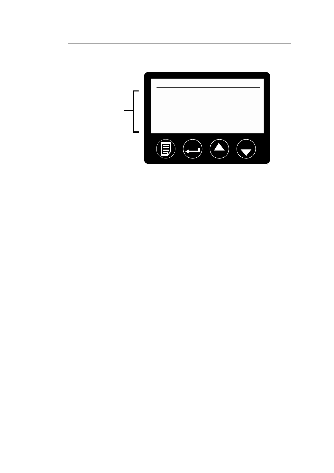
4.1.6 Onboard control panel
The Exterior 1200 Wash features an onboard control panel and text-based LCD display.
The onboard display and control panel allows the user to:
• obtain feedback about the luminaire – this is especially useful for service and
maintenance purposes
• configure the luminaire’s basic personality settings
• set up stand-alone operation
• set up the luminaire’s DMX address so that commands can be sent to a specific
luminaire from a DMX controller
Display
When the luminaire is powered on, the control panel displays information about the
luminaire in two lists that it switches between approximately every 5 seconds:
•The Fixture status list displays information about luminaire temperature and fan
speed in RPM (revolutions per minute)
•The Lamp status list displays a list of resettable counters that indicate hours of lamp
use, number of times the lamp has been struck (powered on) and number of times the
luminaire has been powered on.
Control panel
The display and control buttons are protected by a clear cover that is secured with Allen
screws. Remove the cover for access to the control buttons and replace it when access is
no longer required.
Use the control panel buttons as follows:
•Use the Menu button to open the menus or to navigate one level higher up in the menu
structure.
•Use the Enter button to open a sub-menu, confirm a command or set a value.
•Use the Up and Down buttons to move up and down a list, toggle between options or
increase and decrease a value.
Ext1200 @101 20:20
Fixture address
Standalone
Personality
Info
Manual
Utility
Luminaire type DMX address Time
Menu Enter Up Down
Menus and
options
Figure 12: Control panel and LCD display

General 29
By default, the display backlight goes out automatically 2 minutes after the lamp is turned
on. The backlight returns to its preset intensity level as soon as a control button is
pressed, or in the event of an error or warning message.
A backlight can be switched on, making the display easy to read in the dark, via the Set
backlight level command in the Personality menu. The brightness of the display
can be adjusted from 100 (maximum) to zero (off).
See "9.3: Onboard control panel menus" on page 74 for a complete overview of the
options available in the onboard control panel.
Self-diagnostic feedback messages
In the event of a problem, the Exterior 1200 Wash will show a message in the display
indicating the type of problem that has occurred.
4.1.7 Cooling fans
When power is applied, cooling fans run at full speed for a few seconds to clear any dust
that has accumulated in the heat exchanger. After this, fan speed is regulated
thermostatically to maintain an even temperature in the luminaire. When the lamp is
switched off without cutting power to the luminaire, fans remain active.
4.1.8 LEDs and operating status
Two LEDs on the rear panel indicate the Exterior 1200
Wash’s operational status. The LEDs are visible from a
distance.
Normal operation is indicated when LED 1 lights green. LED 2
lights green when a valid DMX signal is being received. See
Table 5 on page 73 for other status messages.
The LEDs flash off for a brief instant at regular intervals to prevent false readings when
the light sensor samples the light level.
LED 1 LED 2 SENSOR

30 Exterior 1200 Wash user manual

General 31
Section 5. Settings and configuration

32 Exterior 1200 Wash user manual
5.1 Luminaire settings
This section describes how to set up luminaires for either:
• single fixture stand-alone operation, in which individual luminaires run programmed light
shows independently,
• sync
hronized stand-alone operation, in which one master luminaire sends signals to
client luminaires on a data link so that light shows are synchronized, or
• DMX operation, in which luminaires on a data link are controlled remotely using a DMX
control device.
There are three ways to set up luminaires:
MUM (Multi-
Utility
Manager)
The Martin MUM (Multi-Utility Manager) is a PC software
application available from Martin Architectural in a set
(P/N 90758090) that also includes a DABS1 interface
adaptor and suitable cables. The set allows a PC to be
connected to a luminaire via a data link or RJ-45 service
socket.
We recommend MUM because it provides an intuitive,
easy-to-use, graphical user interface.
Note that MUM can only be connected to, and set up,
one luminaire at a time.
Setup using MUM is described in "5.1.1: Setting up a
luminaire with a PC and MUM" on page 33.
Martin MP-2
Uploader
The Martin MP-2 Uploader can be loaded with the
luminaire’s software, available from the Martin
Architectural website, and then connected to the
luminaire.
When working with multiple luminaires, the MP-2 allows
you to apply the same settings to all the luminaires on a
data link.
The MP-2 has a text-based interface and the luminaires
do not provide feedback to the uploader. Therefore, the
current settings of the luminaire can only be “read” by
observing the behavior of the luminaire.
Using the MP-2 is described in "5.1.2: Setting up a
luminaire with an MP-2" on page 36.
Onboard
control
panel
The onboard control panel is a convenient way of
configuring a luminaire with no external equipment, but
access to the luminaire is required.
Setup using the control panel is described in "5.1.3:
Setting up a luminaire with the onboard control panel" on
page 37.
5.1.1 Setting up a luminaire with a PC and MUM
Using MUM, you can connect to and set up one luminaire at a time. Refer to the MUM user
manual for instructions on installing and starting the MUM application.
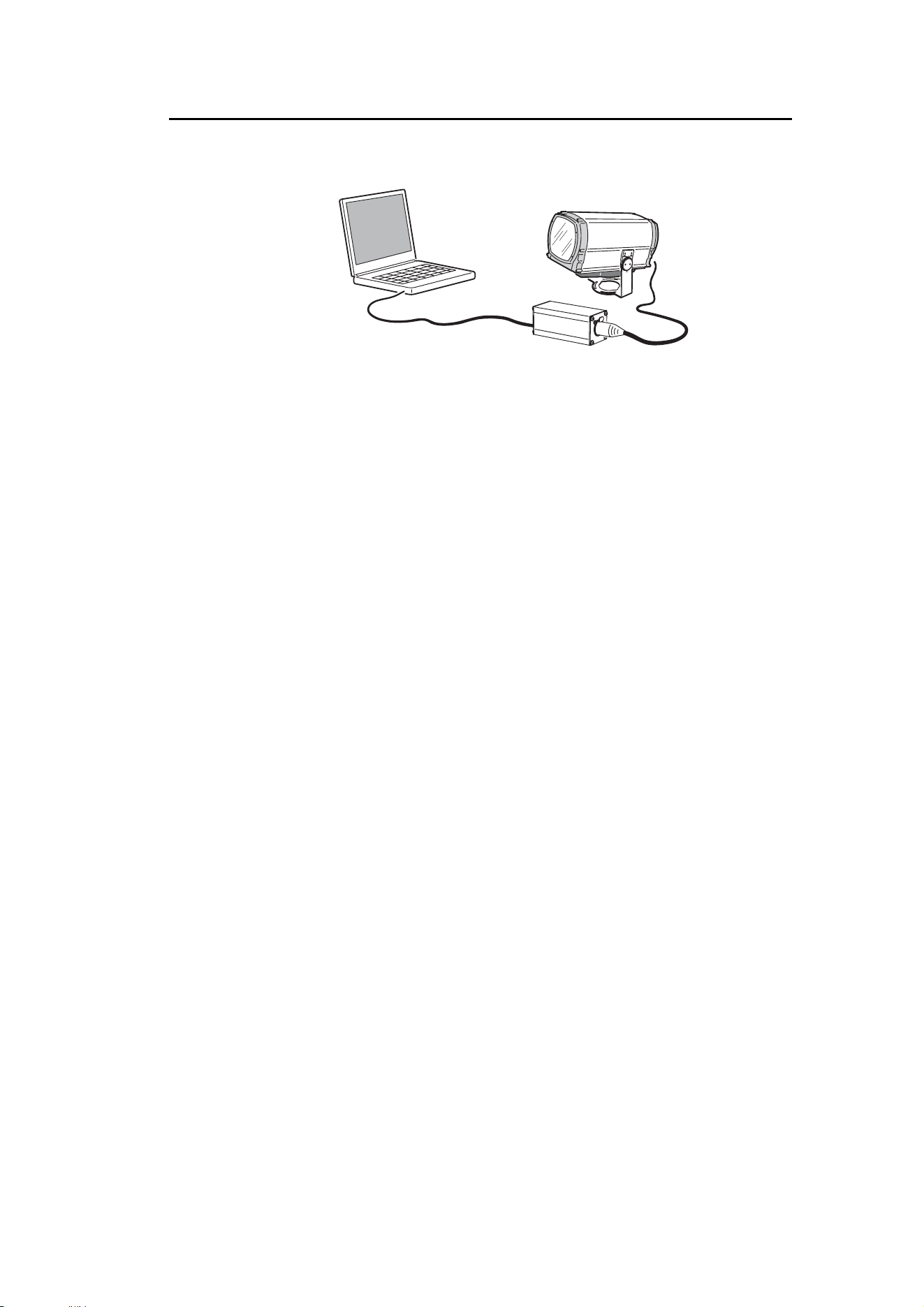
Connecting a PC with MUM
To connect a PC with MUM to an Exterior 1200 Wash:
1. Obtain the MUM application, a DABS1 adaptor and interface cables. These are available as
a set from Martin Architectural, P/N 90758090.
2. Connect the DABS1 adaptor to your PC using the USB cable.
3. Connect the DABS1 adaptor to the Exterior 1200 Wash using either an XLR connector
connected to the data link or the RJ-45 service socket in the connections compartment
behind the rear cover plate (see G in Figure 11 on page 24). If connecting via the data link,
note that you may only connect to one luminaire at a time.
4. Apply power to the Exterior 1200 Wash and start the MUM application. The application will
automatically detect an Exterior 1200 Wash if it is powered on and correctly connected. It
will also retrieve information and current settings from the luminaire and display them.
PC
DABS1
Luminaire
Figure 13: Connecting to a PC with MUM
34 Exterior 1200 Wash user manual
Configuring a luminaire with MUM
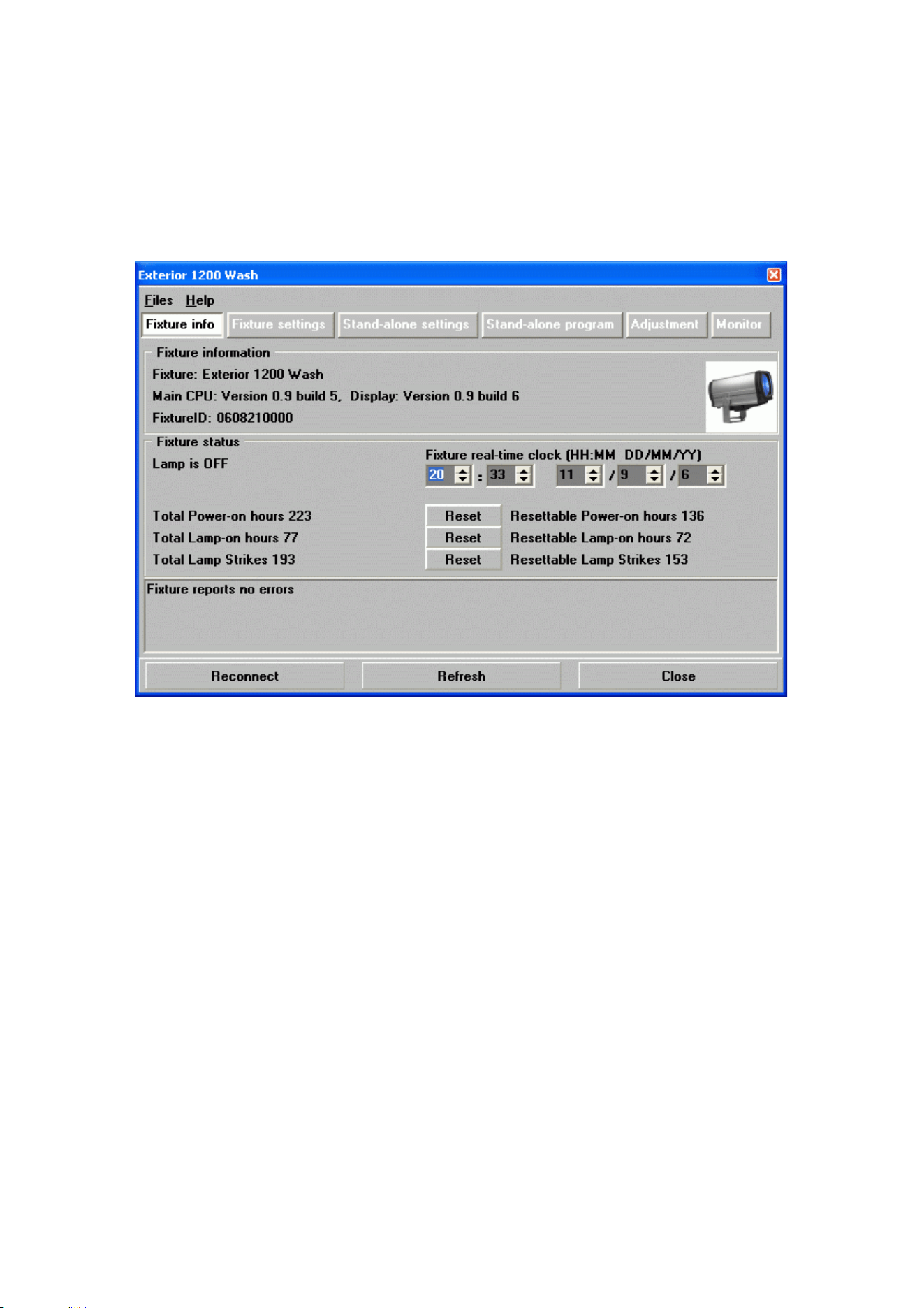
Clock
The Exterior 1200 Wash has a battery-operated 24-hour clock that is used to start and
stop stand-alone operation.
To set the clock:
1. Click on the Fixture Info button in MUM.
2. Using the Fixture real-time clock spin buttons, set the luminaire to the current time
(expressed in the 24-hour clock in hours and minutes) and date. The time will be
updated in the luminaire in real time.
Luminaire settings 35
Luminaire settings
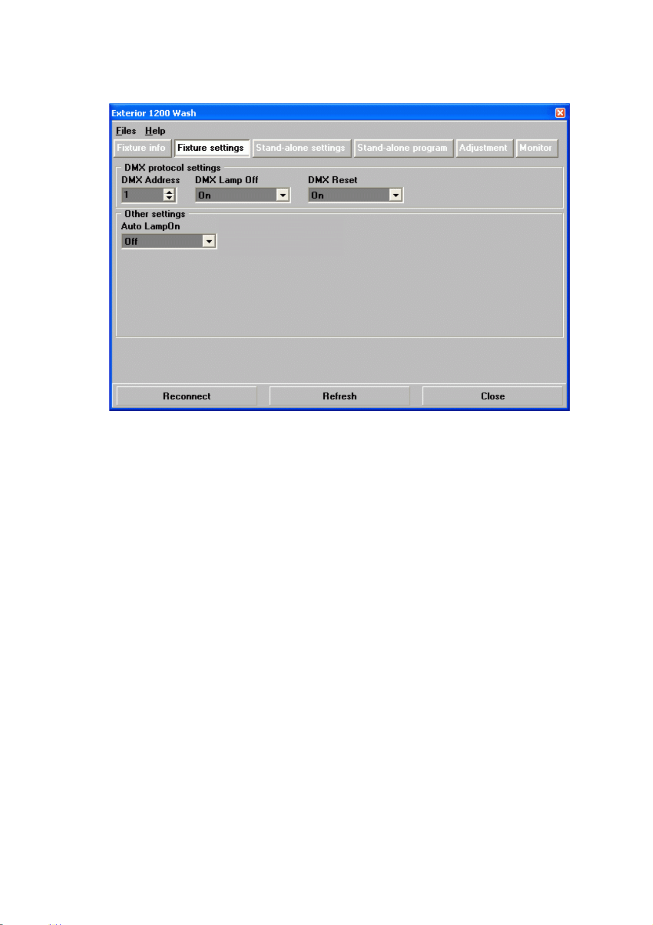
To access the luminaire settings using MUM, click on the Fixture settings button.
DMX address, DMX Lamp Off and DMX Reset settings
If you intend to operate the Exterior 1200 Wash with a DMX controller, the DMX address
must be set on all luminaires for which individual control is required. If you are not familiar
with the principles of DMX addressing in an installation with multiple fixtures, see "7.1.1:
Setting DMX addresses" on page 50.
It is also a good idea to set the DMX Lamp Off and DMX Reset options. These settings
are described in "7.1: Preparing for DMX control" on page 50.
The other default luminaire settings listed below are suitable for most applications, and it
may not be necessary to change them.
Automatic lamp on
When the Automatic Lamp On personality is On, the luminaire turns on the lamp within
90 seconds of power on. When set to Off (the default setting), a lamp-on command is
required to turn on the lamp.
36 Exterior 1200 Wash user manual
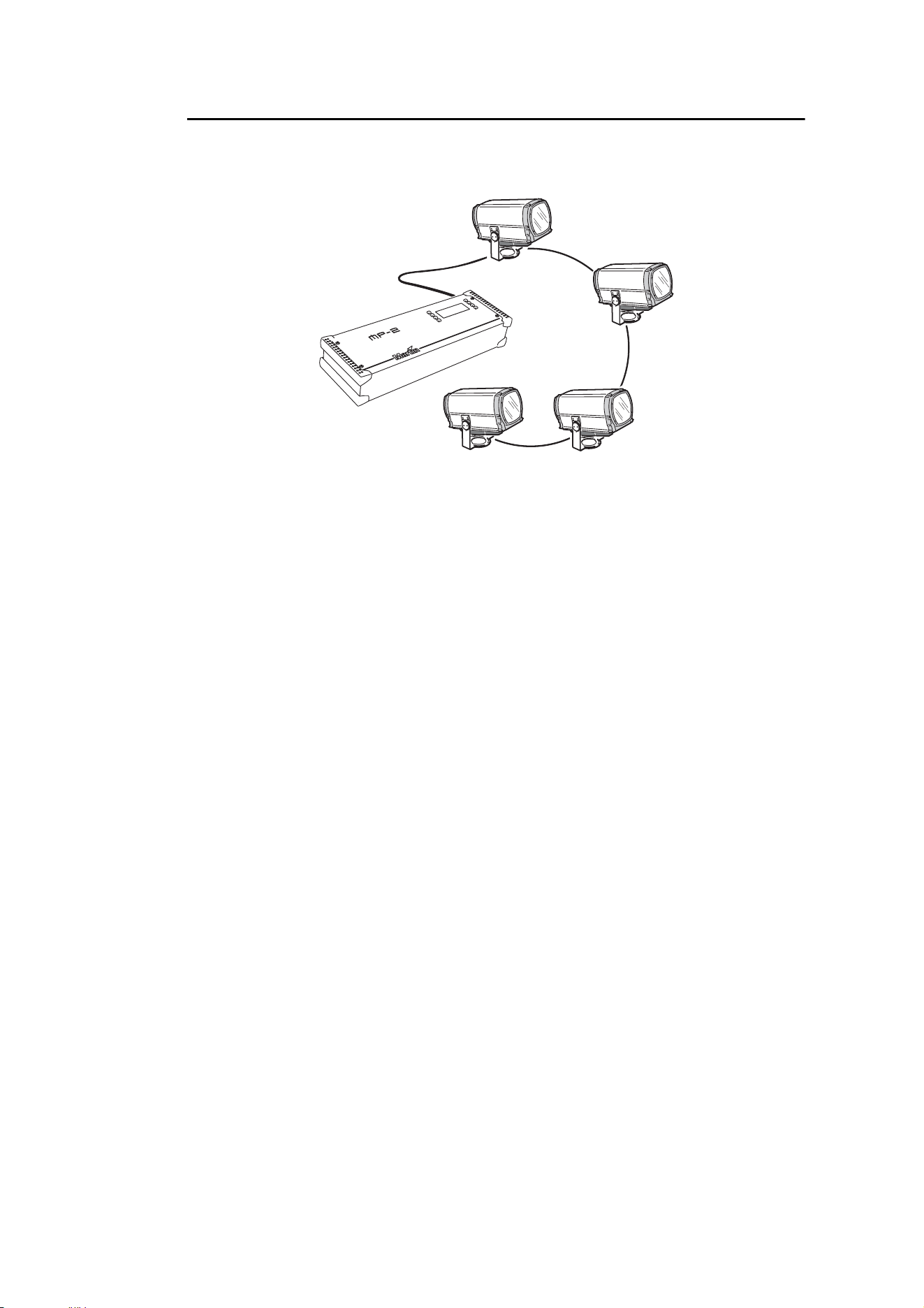
5.1.2 Setting up a luminaire with an MP-2
The Martin MP-2 Uploader can be connected to one or more luminaires. If multiple
luminaires are connected together to an MP-2, the settings applied will be sent to all the
luminaires.
Connecting an MP-2
To connect an MP-2 Uploader to an Exterior 1200 Wash:
1. Obtain an MP-2 (available from Martin Architectural, P/N 90758420) with a flash
memory card, and the Martin Uploader program (available free of charge from the
Martin website). Download the Exterior 1200 Wash luminaire software from the Martin
website as described in the Martin Uploader help file and MP-2 user manual.
2. Connect the MP-2 to the Exterior 1200 Wash using either an XLR connector
connected to the data link or the RJ-45 service socket in the connections compartment
behind the rear cover plate.
3. Apply power to the Exterior 1200 Wash and MP-2.
Configuring the Exterior 1200 Wash with the MP-2
See "9.4: MP-2 control menus" on page 75 for a complete overview of the control menus
available for the Exterior 1200 Wash in the MP-2 Uploader.
DMX address
If you intend to use a DMX controller, you need to set the luminaire’s DMX address. If you
want a group of luminaires to respond identically and do not need individual control,
connect the MP-2 to all the luminaires in that group. The DMX address you set will be
given to all the luminaires.
If you are not familiar with the principles of DMX addressing in an installation with multiple
fixtures, see "7.1.1: Setting DMX addresses" on page 50.
To set the DMX address, scroll through the MP-2 menus and select Fixture address.
Enter a value between 1 and 505 (512 DMX channels are available in one DMX universe,
and the Exterior 1200 Wash uses 8 channels).
Figure 14: Connecting to an MP-2 Uploader

Luminaire settings 37
Clock
The Exterior 1200 Wash has a battery-operated 24-hour clock that is used to start and
stop stand-alone operation.
To set the clock:
1. Scroll through the MP-2 menus and select Adjust → Real time clock.
2. Set the luminaire to the current time (expressed in the 24-hour clock in hours and
minutes) by scrolling through and entering values for Hour and Minute.
Luminaire settings
Luminaire settings are accessed under Personality in the MP-2 menus.
DMX Lamp Off and DMX Reset settings
If DMX will be used to control the luminaire, it is a good idea to set the DMX Lamp Off and
DMX Reset options via Personality → DMX lamp off and Personality → DMX
reset. These settings are described in "7.1: Preparing for DMX control" on page 50.
The other default luminaire settings listed below are suitable for most applications, and it
may not be necessary to change them.
Automatic lamp on
When Personality → Auto lamp on is set to On, the luminaire turns on the lamp
within 90 seconds of power on. When set to Off (the default setting), a lamp-on
command from the DMX controller is required to turn on the lamp.
5.1.3 Setting up a luminaire with the onboard
control panel
DMX address
If you intend to use a DMX controller, you need to set the luminaire’s DMX address. If you
are not familiar with the principles of DMX addressing in an installation with multiple
fixtures, see "7.1.1: Setting DMX addresses" on page 50.
To set the DMX address:
1. Press the Menu button to enter the main menu and use the Up and Down buttons if
necessary to select Fixture address.
2. Press Enter.
3. Use Up and Down to enter a value between 1 and 505 (512 DMX channels are
available in one DMX universe, and the Exterior 1200 Wash uses 8 channels).
Pressing Up and Down simultaneously sets the DMX address to 1.
4. Press Enter to confirm your choice and return to main menu. If you press Menu, you
will return to the main menu without saving the address you entered.
Clock
The Exterior 1200 Wash has a battery-operated 24-hour clock that is used to start and
stop stand-alone operation.
To set the clock:
1. If the display is showing Fixture status and Lamp status, press Menu to enter
the main menu. Scroll down to Personality. and press Enter.

38 Exterior 1200 Wash user manual
2. In the Personality menu, scroll down to Set clock.
3. Set the luminaire to the current time (expressed in the 24-hour clock in hours and
minutes) by entering values for Hour and Minute. Use the Up and Down buttons to
scroll values and Enter to confirm.
Luminaire settings
Luminaire settings are accessed in the Personality menu.
DMX Lamp Off and DMX Reset settings
If DMX will be used to control the luminaire, it is a good idea to set the DMX Lamp Off and
DMX Reset options via Personality → DMX Lamp Off and Personality → DMX
Reset. These settings are described in "7.1: Preparing for DMX control" on page 50.
Automatic lamp on
When Personality → Auto Lamp On is set to On, the luminaire turns on the lamp
within 90 seconds of power on. Use this setting if you intend to run stand-alone shows.
When set to Off (the default setting), a lamp-on command from the DMX controller is
required to turn on the lamp.

Luminaire settings 39
Section 6: Stand-alone operation
40 Exterior 1200 Wash user manual
6.1 Stand-alone programming: general
DANGER! Read "Safety information" on page 4 before programming or
operating the Exterior 1200 Wash.
6.1.1Introduction
Stand-alone operation is a mode where the luminaire executes color changes at set
intervals and speeds, at pre-defined periods during the day, and/or when the light level
falls below a defined level. The term stand-alone is used to mean that the Exterior 1200
Wash is not connected to a control device, but is pre-programmed with a series of up to
20 scenes that play continuously in a loop.
An Exterior 1200 Wash can run a stand-alone show independently or with synchronized
scene changes with other Exterior 1200 Wash luminaires and most other Martin
Architectural luminaires (see "6.1.2: Synchronized operation with multiple luminaires" on
page 40 for details).
About scenes
A stand-alone light show consists of scenes. Each scene is a particular lighting effect with
predetermined color, intensity and duration. Up to 20 scenes can be programmed into the
Exterior 1200 Wash’s program memory.
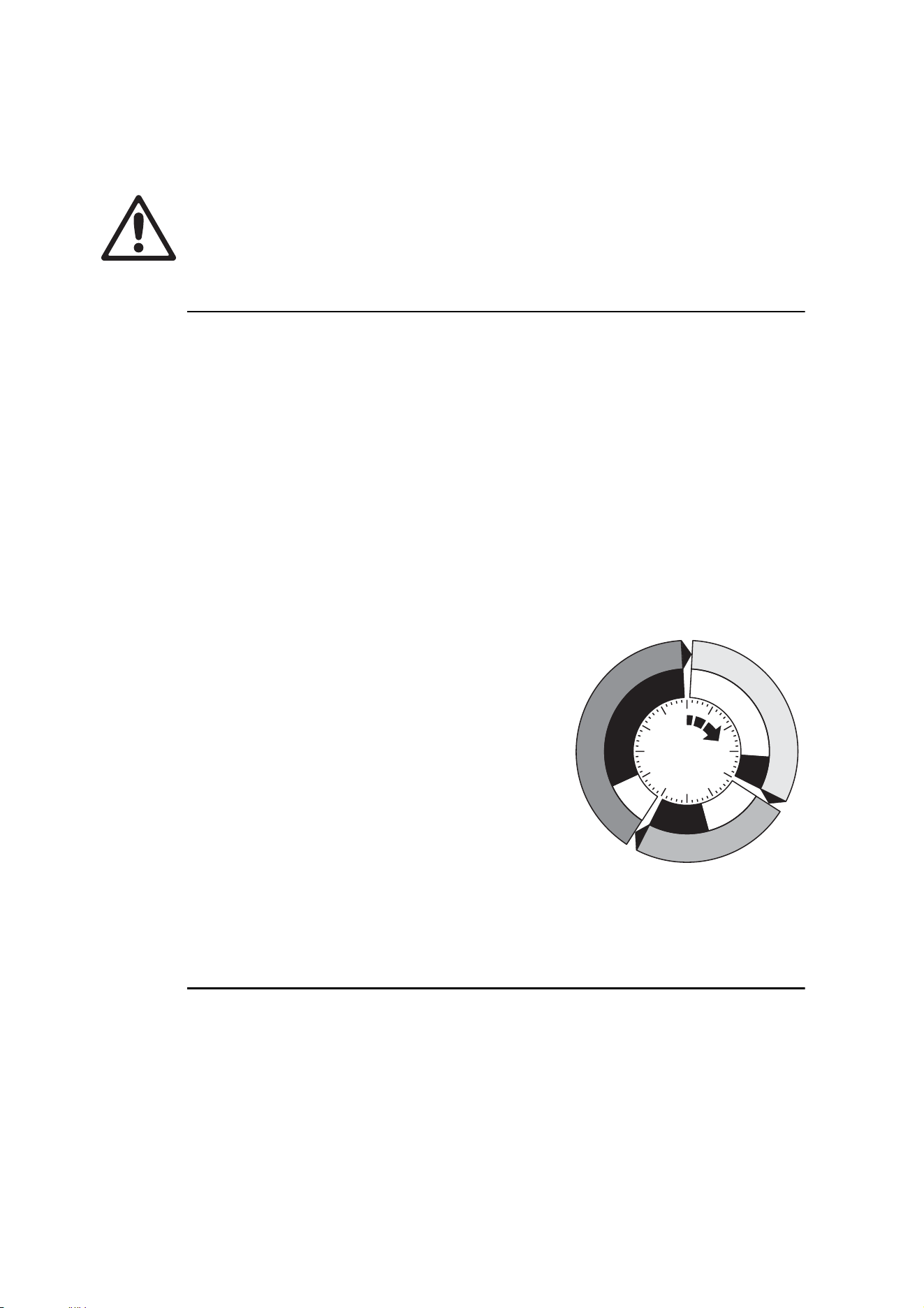
Each scene has a dynamic part – the fade – during
which effects move to the scene’s programmed
positions, and a static part – the wait – where effects
do not change.
The duration of the fade and wait is programmed
individually for each scene. The fade time may be 0 -
120 seconds; the wait time may be 1 second to 12
hours. The total time it takes a scene to execute is
the sum of the fade and wait times.
6.1.2 Synchronized operation
with multiple luminaires
If you are running multiple luminaires on a data link, you can synchronize action so that all
luminaires start their programmed shows and start fading to the next scene at the same
time.
An Exterior 1200 Wash running a stand-alone show can perform synchronized scene
changes with other Exterior 1200 Wash luminaires as well as Martin Architectural
luminaires of the following types:
• Exterior 200
Fade
Fade
S
c
e
n
e
1
S
c
e
n
e
1
S
c
e
n
e
3
S
c
e
n
e
3
S
c
e
n
e
2
S
c
e
n
e
2
Wait
Wait
Wait
Fade
Figure 15: Scene timing

Stand-alone programming: general 41
• Exterior 600
• Exterior 600 Compact
• Inground 200 CMY
• FiberSource CMY150
• Imager series
• Alien 02 series
• MiniMAC Maestro
In sync
hronized operation, one luminaire is set as the master and the others are set as
clients. Each luminaire must be programmed with its own show. When the master fades
to the next scene or starts its show from the beginning again, it tells each client luminaire
to fade to its next scene or start its show again. In other words, each client luminaire will
run its show repeatedly in a cycle, changing scene when prompted to by the master, until
the master finishes its own show and signals that all luminaires should start from the first
scene once again.
If you want to keep things as simple as possible when programming synchronized
operation, ensure that:
1. Every luminaire has the same number of scenes.
2. Scene times are a few sec
onds longer on the master luminaire than on client
luminaires (this will ensure that client luminaires always have time to finish scenes
before the master tells them to start the next scene).
It is important to note that the only commands transmitted by the master are scene
change and show start commands. No data about the appearance of the scene is
transmitted between luminaires.
For a more detailed explanation of synchronized operation and how advanced effects can
be created by programming luminaires with a different number of scenes, see the next
section.
Synchronized stand-alone operation: detailed description
Note: This section gives advanced information about stand-alone synchronized
operation. You only need to read it if you require help with problem
diagnosis or if you want to program advanced synchronized light shows.
The principles in stand-alone synchronized operation are as follows:
1. A scene c
ontains a fade section, followed by a wait section
2. Eac
h luminaire can be individually programmed with up to 20 scenes, and each scene
can have its own indiv
idual fade and wait times.
3. Scenes are numbered from 0 to 19.
4. In synchronized operation, one master luminaire issues commands to the other client
luminaires to "go to scene xx", where xx is the scene number that the master will
execute next.
5. If a client has fewer scenes
than the master, it will derive which scene to go to by
dividing the number of the scene it has been commanded to go to (scene 5, for
example) by the total number of scenes that the client luminaire has (4, for example) in
whole numbers (no decimal plac
es). In this example 5 divided by 4 results in 1, with 1
remainder. This remainder will be the number of the scene that the c
lient luminaire
starts - scene 1. Generally though, when a client luminaire reaches its own last scene
before the Master luminaire, a "go to scene xx" message will result in the first scene
being played.
42 Exterior 1200 Wash user manual
6. If a client has more scenes than the master calls, the last scenes in the client will never
be executed, as is the case with scene S4 in the following example.
7. In synchronized operation, the wait time is determined by the master. Ev
ery client
luminaire fades and waits at its own rate and then remains in the “wait” state until it
receives a “start scene xx” command from the master.
8. A client luminaire will not listen for the next message from the master luminaire before
it has finished its current scene. This may result in a client skipping a scene if the client
has a longer scene time than the master. Note that in the following example, the
scenes in the client run out of their programmed sequence because scenes 0 and 2 on
the client are longer than the corresponding scenes on the master.
6.1.3 Stand-alone programming methods
The Exterior 1200 Wash provides three stand-alone programming methods; using:
1. the Martin MUM application on a personal computer (recommended because it
provides an intuitive, easy-to-use, graphical user interface),
2. an MP-2 Upload device, or
3. the luminaire’s onboard control panel.
If you are programming a group of luminaires to perform the same scenes with
synchronized triggering, we recommend that you either:
• Use an MP-2 Uploader to s
imultaneously program the same show on all luminaires
connected to the data link, or
• Use MUM to program a show on one client luminaire, download and save this
luminaire’s program and settings to your PC using MUM’s Files menu, and then upload
the program and settings to each subsequent luminaire that you connect to.
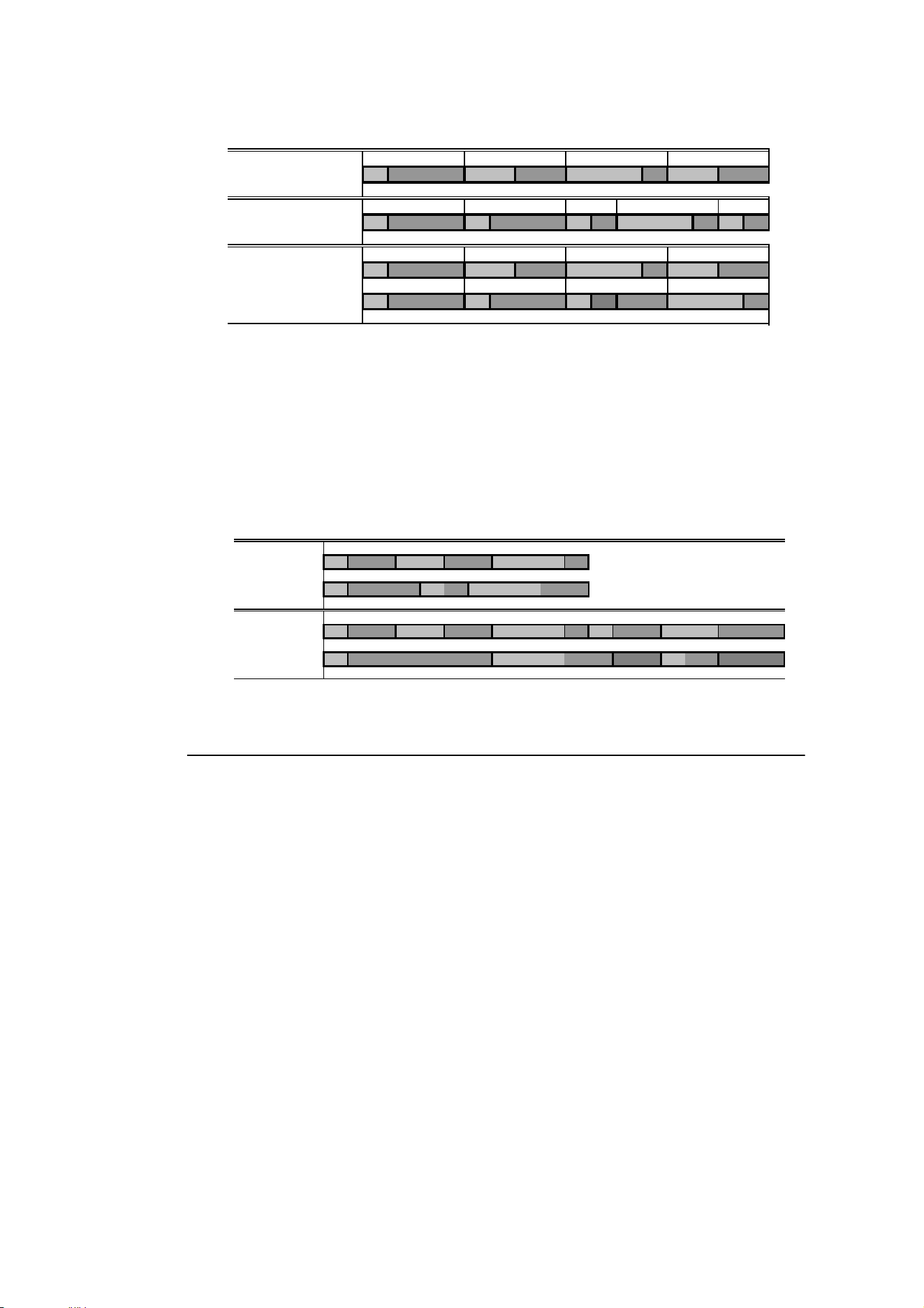
F=fade, W=wait Timeline =>
M0 M1 M2 M3
Programmed in Master F W F W F W F W
S0 S1 S2 S3 S4
Programmed in Client
F W F W F W F W F W
Result M0 M1 M2 M3
FW FWF WFW
S0 S1 S2 S3
FW FW FW ----F W
M=master, S=client
F=fade, W=wait Time >
Programmed M0 M1 M2
Master F W F W F W
S0 S1 S2
Client
F W F W F W
Result M0 M1 M2 M0 M1
Master F W F W F W F W F W
S0 S2 S1
Client
F W F W .. .. FW .. ..

Stand-alone programming with a PC and MUM 43
6.2 Stand-alone programming with a PC
and MUM
DANGER! Read "Safety information" on page 4 before programming or
operating the Exterior 1200 Wash.
The programming of stand-alone shows and setting up of master/client operation is best
performed from a personal computer using the Martin MUM (Multi-Utility Manager)
application. The computer is connected to a luminaire via a DABS1 interface, used to
program the stand-alone settings
for that luminaire, and then removed. Once a luminaire
is subsequently switched on, it can automatically run the scenes in its program in a loop,
according to the triggering criteria you have specified (time of day, and/or light level).
If you are not familiar with the use of MUM, it is recommend that you familiarize yourself
with it by reading the MUM Help files and MUM user manual.
6.2.1 Connecting
To establish a connection:
1. Connect a DABS1 adaptor to a PC and to the Exterior 1200 Wash.
2. Power on the Exterior 1200 Wash and start the MUM application. The application w
ill
a
utomatically detect an Exterior 1200 Wash if it is powered on and corr
ectly
connected. It will also retrieve the luminaire’
s current settings and display them.
44 Exterior 1200 Wash user manual
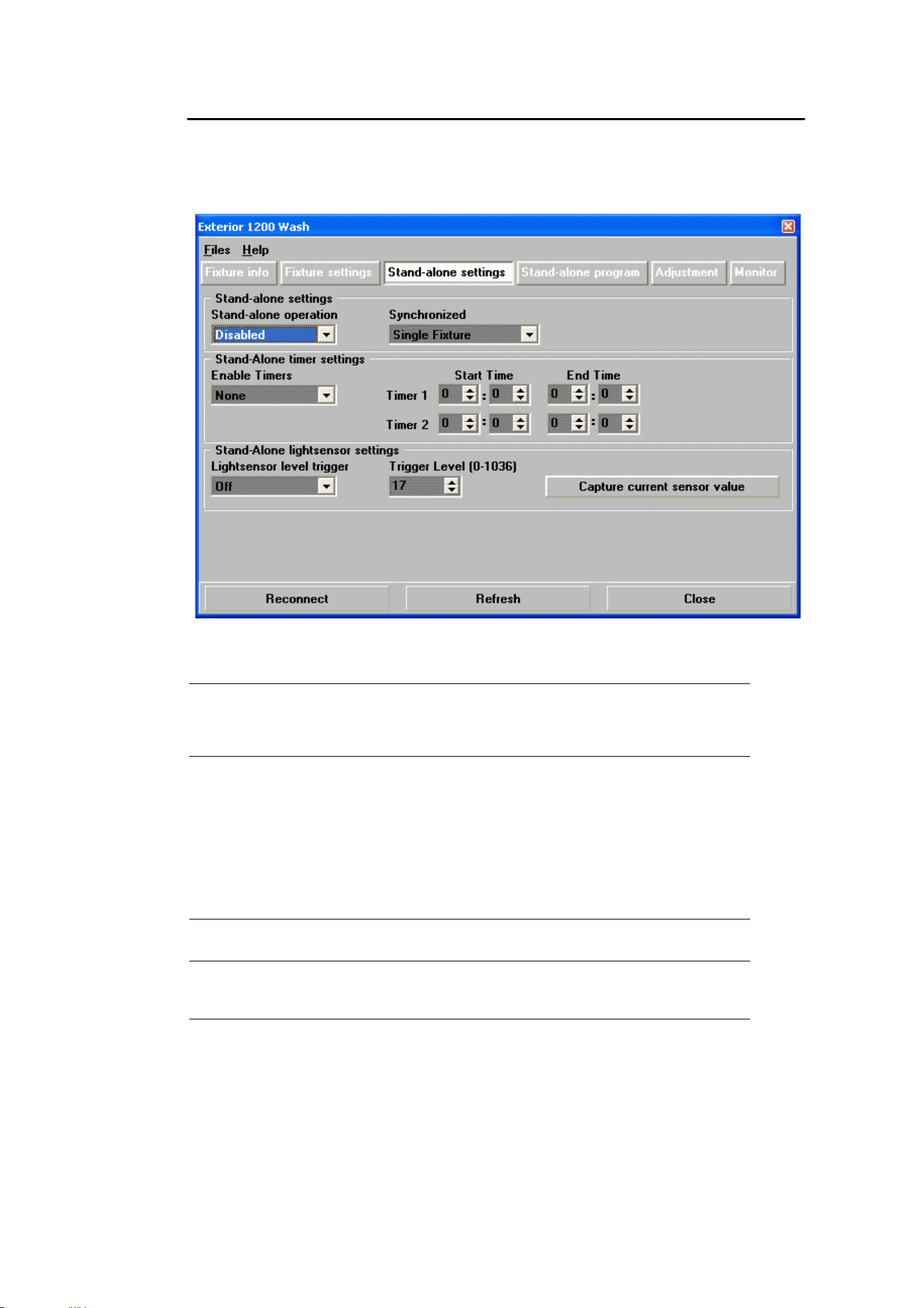
6.2.2 Stand-alone settings
First, the luminaire needs to be configured to know if and when to activate a stand-alone
program:
Click Stand-alone settings to display the window below.
The following options are available:
Automatically triggering stand-alone operation
Stand-alone operation can be set to a timer trigger that activates operation for one or two
periods in a 24 hour period, or set to a light-level trigger that uses a light sensor to activate
operation when ambient light is below a certain level.
Stand-alone
operation
Activates or deactivates stand-alone operation. If enabled,
stand-alone operation will start automatically when the
luminaire is powered on, or the luminaire is being controlled
by DMX and the DMX control signal disappears.
Synchronized Sets the luminaire to one of the following modes:
Single Fixture: operates in stand-alone mode independently
of other luminaires
Master: sends trigger signals
to other luminaires, or
Synchronized: client – receives trigger signals from other
luminaires.
No more than one luminaire may be the master. Any
luminaire on the link, regardless of its position, may be the
master. All other luminaires must be set as clients.
Stand-alone
timer settings
See "Setting a timer trigger" on page 45.
Stand-alone
light sensor
settings
See "Setting a light-level trigger" on page 45.
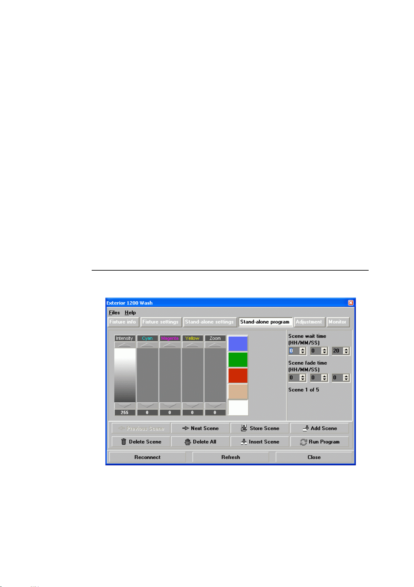
Stand-alone programming with a PC and MUM 45
If both the timer and the light-level trigger are used, operation starts whenever it is darker
than the light-level setting, and within the times set.
Setting a timer trigger
To set a timer trigger:
1. Make sure the correct time has been set on the luminaire’s built-in clock (see "Clock"
on page 34).
2. Select None, Timer 1, Timer 2 or Both Timers in the Enable Timers box.
3. Use the Start Time and End Time spin buttons to set a period of stand-alone
operation on the selected timer(s).
Setting a light-level trigger
To set a light-level trigger:
1. Set Light level sensor trigger to On.
2. Set the light level that triggers stand-alone operation using the Trigger level spin
button, or press Capture current sensor value to set the current ambient light level to
trigger stand-alone operation.
To avoid false triggering by sudden light changes caused by vehicle headlights or clouds,
for example), the light level must remain above or below the trigger threshold for 5
minutes to activate the trigger.
6.2.3 Programming effects in scenes
The programming of effects is performed using the Stand-Alone program controls:

46 Exterior 1200 Wash user manual
The following options are available:
When setting scene fade and scene wait times for luminaires in synchronized operation,
avoid unex
pected problems by making sure that each scene time is slightly longer in
the master luminaire than in the client luminaires (see "6.1.2: Synchronized operation
with multiple luminaires" on page 40 for full details).
Scene management
Once you have specified a mix of effects, you can store the scene using the options
available under the Program menu:
When the program is run, scenes execute in a c
ontinuous, ascending loop.
Note that, if a “client” luminaire has:
• Fewer scenes than the master luminaire, it will run these in a cycle continuously, until the
master luminaire signals that the program should start from the beginning again.
Intensity The dimmer provides smooth, high-resolution 0 - 100%
dimming.
Cyan
Magenta
Yellow
The CMY color mixing system is based on graduated cyan,
magenta, and yellow color filters. A full spectrum of colors can
be achieved by varying the amount of each filter from 0 to
100%.
Note that mixing 3 colors results in loss of light - the light is
blacked out when all 3 colors are fully applied. For maximum
brightness, mix only 2 colors at a time.
Zoom The lens can be driven forwards or backwards to vary the size
of the beam.
Filter color
buttons
Clicking on the five square colored buttons selects positions on
the color wheel. As standard, the color wheel has red, green,
and blue dichroic color filters, a 5500 to 3400 K dichroic CTC
filter and an open (white) position. It can be used alone or in
combination with CMY color mixing.
Scene fade
time
The fade time, anything from 0 to 120 seconds, is the time it
takes to change from one effect to another.
Scene wait
time
This is the duration a color is applied. A wait time can be from 1
second to 12 hours.
Store scene Save settings in the current scene.
Add scene Save settings in a new scene at the end of the current
sequence of scenes.
Insert scene Save settings in a new scene before the current scene. Tip:
Think of the Add and Insert commands as Save commands, to
be used as the last step after programming all effects.
Delete
scene
Remove the current scene from memory. Scenes after the
deleted scene are renumbered.
Next scene Step to the next scene.
Previous
scene
Step to the previous scene.
Delete all Remove all scenes from the luminaire memory.
Run
program
Run the scenes in the programmed light show.
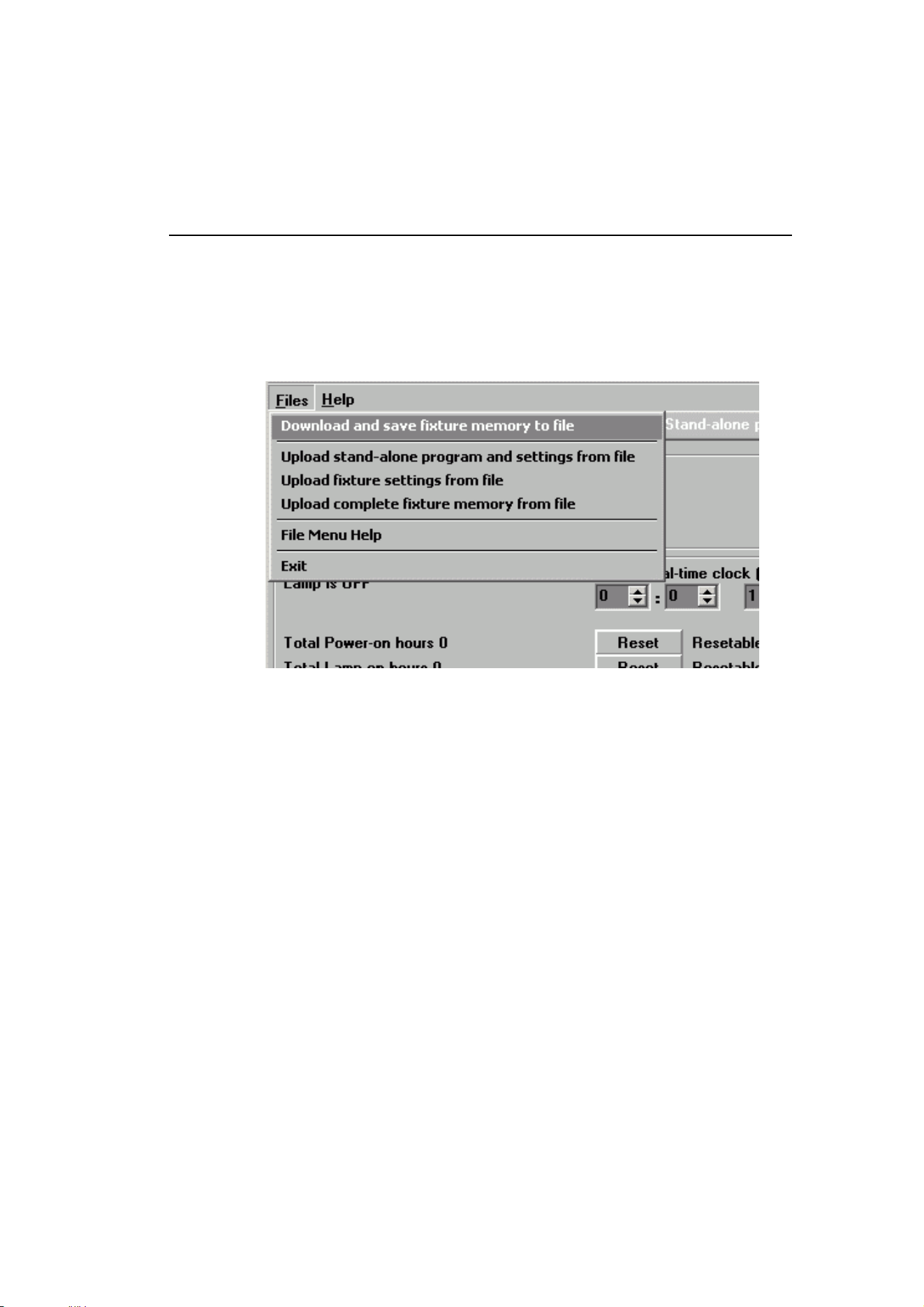
• More scenes than the master luminaire, then the additional scenes will never run, because
the program will reset to the first scene when the master starts its program from the
beginning.
6.2.4 Programming the same stand-alone show on
multiple luminaires
Although you can only connect to and program a single luminaire at a time using the MUM
application, you can use MUM to program a single luminaire, then use the commands in
MUM’s Files menu (see illustration below) to download and save the luminaire’s settings to a
file on your PC, and then upload the stand-alone program and luminaire settings to each
subsequent luminaire that you connect to. This is useful if you have a group of luminaires of the
same type that will run the same stand-alone show.

48 Exterior 1200 Wash user manual
6.3 Stand-alone operation
6.3.1 Starting show playback automatically at
luminaire power-on
Execution of the pre-programmed scenes in a loop will automatically resume when the
luminaire is powered on if stand-alone operation and the automatic lamp-on function are
enabled by one of the following three methods:
Using MUM:
• Stand-alone operation in the Stand-alone settings window
• Auto LampOn In the Fixture Settings window
Using an MP-2:
• Stand Alone → Enable SA
• Personality → Auto lamp on.
Using the onboard control panel:
• Standalone → Enable
• Personality → Automatic Lamp On.
6.3.2 DMX controller override during stand-alone
show playback
If an Exterior 1200 Wash is connected to a DMX controller and receives DMX signals
during show playback, the stand-alone show will stop running and the luminaire will
respond to the DMX controller. DMX signals always have priority over the running of a
stand-alone show.

Stand-alone operation 49
Section 7. DMX control

50 Exterior 1200 Wash user manual
7.1 Preparing for DMX control
DANGER! Read "Safety information" on page 4 before programming or
operating the Exterior 1200 Wash.
To control a luminaire via DMX, it must be set up to respond to commands from the
controller on specific DMX channels. This chapter describes how to set this up. It also
describes DMX lamp off and DMX reset settings that you may wish to alter.
You can use a personal computer with the Martin MUM (Multi-Utility Manager) application
running on a PC, a Martin MP-2 Uploader or a Martin DAD (DMX Addressing Device) to
prepare your Exterior 1200 Wash. Of these options, MUM is the easiest to use because it
has a graphical user interface.
Follow the instructions in "5.1: Luminaire settings" on page 32 to choose and connect a
setting device, and then refer to this chapter for information about specific settings.
7.1.1 Setting DMX addresses
If individual control of each Exterior 1200 Wash is required, each luminaire must be set up
to receive instructions from the DMX controller on a group of DMX channels that are not
used by any other device in its DMX universe. The DMX address, also known as the
control address or start channel, is the first of these channels. Each luminaire uses this
channel and the channels immediately above it to receive instructions.
Exterior 1200 Wash Narrow, Medium, Wide and Very Wide models use eight DMX
channels, i.e. the start channel plus the next seven channels. If the control address is set
to 100, the luminaire uses channels 100, 101, 102, 103, 104, 105, 106, and 107. Channel
108 is available as the DMX address for the next luminaire.
If two or more luminaires are set up with the same address, they will receive the same
instructions and behave identically. Setting up identical luminaires with the same address
is a good tool for troubleshooting unexpected behavior and an easy way to achieve
synchronized action.
DMX addressing with MUM
To set a DMX address using the MUM application, use the DMX Address spin button in
the in the Fixture Settings window. The luminaire’s DMX address is updated in real time.
MUM can only set the DMX address on one luminaire at a time, and must be connected to
one luminaire only via the data link or service port.
DMX addressing with an MP-2 Uploader
To set a DMX address using an MP-2 Uploader, scroll through the menus to Fixture
address and enter the required value. The MP-2 can be connected to multiple luminaires
via the data link, and will set the same address in all the luminaires it is connected to.
DMX addressing with the onboard control panel
To set a DMX address using the onboard control panel, enter the Fixture address
menu and enter the required value.

Preparing for DMX control 51
DMX addressing with a DAD
To set a DMX address using a DAD, follow the instructions in the DAD user manual. The
DAD can only set the DMX address on one luminaire at a time, and must be connected to
one luminaire only via the data link.
7.1.2 DMX Lamp Off option
When the DMX Lamp Off feature is ON (the default setting), lamp power can be turned off
from the controller by setting channel 1 to a DMX value from 248 to 255 (97-100%). When
set to OFF, the Lamp Off command executes only if channels 3, 4, and 5 are set to values
from 230 to 232. Bear in mind that if you turn a lamp off, you must allow it to cool for eight
minutes before you can restrike it.
7.1.3 DMX Reset option
When the DMX Reset feature is ON (the default setting), the luminaire can be reset from
the controller by setting channel 1 to a DMX value from 208 to 217 (81-85%). When DMX
Reset is set to OFF, the reset command executes only if channels 3, 4, and 5 are set to
values from 230 to 232.

52 Exterior 1200 Wash user manual
7.2 DMX controller operation
DANGER! Read "Safety information" on page 4 before operating the Exterior
1200 Wash.
The Exterior 1200 Wash may be operated with any lighting controller that is compatible
with the USITT DMX 512 (1990) or USITT DMX 512A standards.
See "3.3: Installing a data link" on page 22 for connection requirements and "9.5: DMX
protocol" on page 77 for an overview of DMX control channels and values.
If an Exterior 1200 Wash is connected to a DMX controller and receives DMX signals
during stand-alone show playback, the stand-alone show will stop running and the
luminaire will respond to the DMX controller. DMX signals always have priority over the
running of a stand-alone show.
7.2.1 Effect operation
The effects reset to their “home” position when the Exterior 1200 Wash is powered on.
The Exterior 1200 Wash can also be reset from the DMX controller on channel 1. To limit
the possibility of accidentally resetting the luminaire in the middle of a light show, you can
set up the luminaire so that the reset command only works if the CMY channels are all set
to a DMX value from 230 to 232 (see "7.1.3: DMX Reset option" on page 51).
7.2.2 Lamp
Lamp on
With the default setting, the lamp remains off until a “lamp on” command is sent from the
controller. To have the lamp strike automatically, activate the Automatic Lamp On
personality (see "5.1: Luminaire settings" on page 32).
A large peak of electric current is drawn for an instant when striking a discharge lamp.
Striking many lamps at once may cause a voltage drop large enough to prevent lamps
from striking and/or trip circuit breakers. When striking multiple lamps, program a
sequence that strikes lamps one at a time at 5 second intervals. If Automatic Lamp On is
enabled, there is a delay of up to 90 seconds after power is applied before the lamp
strikes. This delay is determined by the luminaire’s DMX address.
Lamp off
The lamp can be turned off from the controller by sending a “lamp off” command on
channel 1. If the DMX Lamp Off personality is OFF (see "7.1.2: DMX Lamp Off option" on
page 51), the command only works if each of the CMY channels (3, 4, and 5) is set to a
DMX value from 230 to 232.
After being turned off, the lamp must cool for at least 8 minutes before it can be turned
back on. “Lamp on” commands sent within 8 minutes of a “lamp off” command are stored
and then executed after 8 minutes have elapsed.

7.2.3 Color
CMY color mixing
The CMY color mixing system is based on graduated cyan, magenta, and yellow color filters. A
continuous range of mixed colors may be achieved by varying the amount of each filter from 0
to 100%. Note that mixing 3 colors results in a loss of light - the light is blacked out when all 3
colors are fully applied. For maximum brightness, mix only 2 colors at a time.
Color wheel
The color wheel has red, green, and blue dichroic color filters plus a 5500 K to 3400 K CTC
(color temperature correction) filter and an open (no filter) position. The color wheel can be
used independently of the CMY system or together with CMY color mixing to increase color
saturation. The wheel scrolls in full steps.
7.2.4 Dimmer
The mechanical dimmer provides smooth, high-resolution 0 - 100% intensity control.
7.2.5 Zoom
On Narrow and Medium models, the beam angle can be varied remotely using a motorized
zoom feature. Depending on the optical configuration of the luminaire, the one-tenth peak
beam angle can be varied within the following limits:
• Exterior 1200 Wash Narrow, 14° - 31°
• Exterior 1200 Wash Medium, 20° - 50°
The zoom is disabled if the temperature inside the luminaire falls below -10° C (14° F) but is re-
activated as soon as the internal temperature rises above this level.
7.2.6 Effects speed (tracking and vector control)
The speed at which effects fade, that is, move from one position to another, can be controlled
in two ways known as tracking control and vector control:
•With tracking control, fades are programmed using the controller’s fade time. The controller
divides the fade into small elements that the luminaire “tracks.” The Exterior 1200 Wash has a
digital filter algorithm that averages several updates to ensure smooth movement.
• Vector control provides a way to program fades on controllers without programmable fade
times or cross-faders. With vector control, instead of breaking up the movement into many
small positions, the controller sends one position value and one speed value and the
luminaire’s own software controls the movement. Vector control may provide smoother fades
than tracking control with some controllers, particularly when the controller is busy with a
large number of processor-intensive operations, and particularly on very slow fades.
You can select tracking or vector control using your DMX controller, but you cannot use both at
the same time.

54 Exterior 1200 Wash user manual

DMX controller operation 55
Section 8. Service and accessories
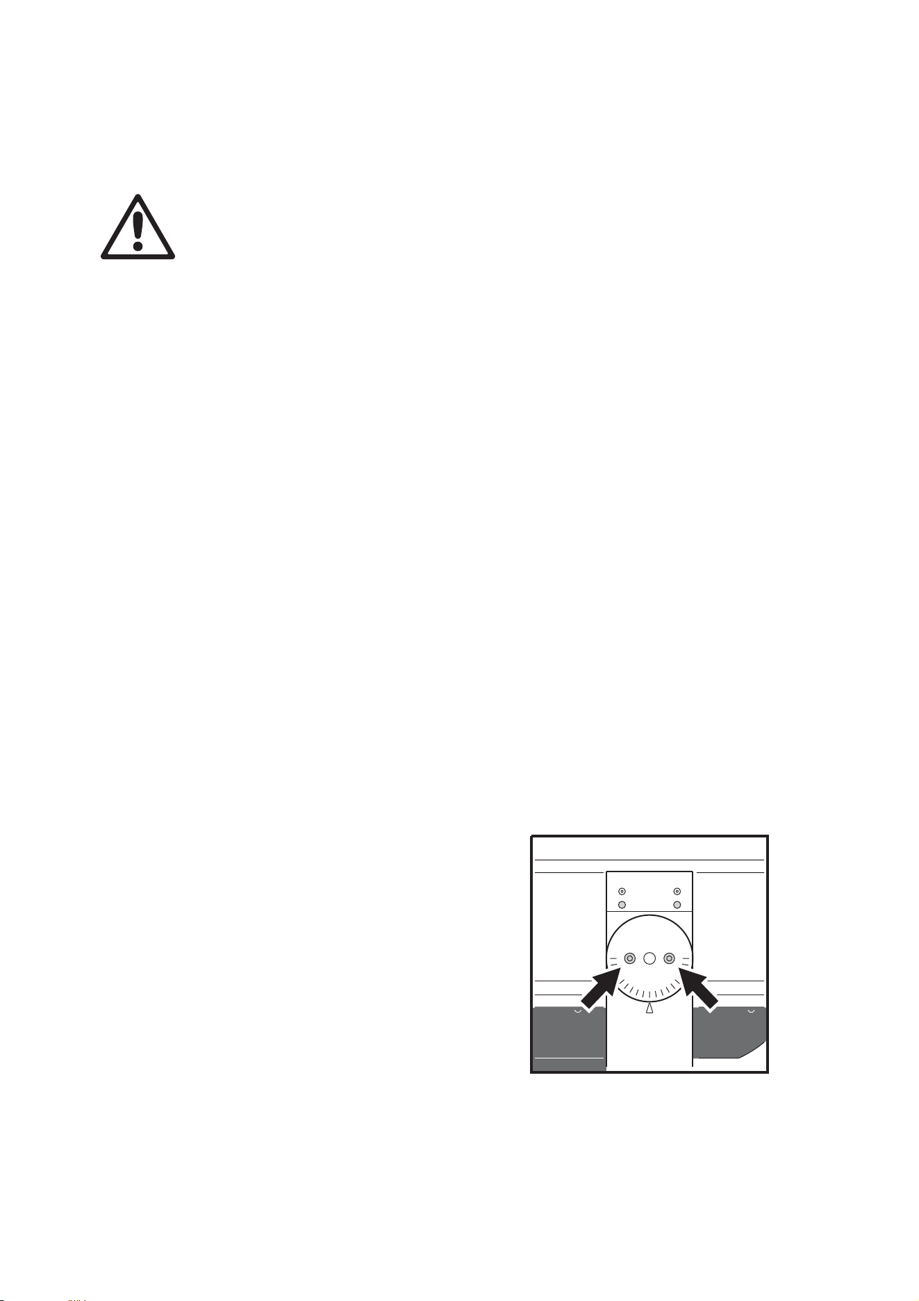
56 Exterior 1200 Wash user manual
8.1 Service: general
DANGER! Read "Safety information" on page 4 before servicing the Exterior
1200 Wash.
Important! The Exterior 1200 Wash requires regular service and
maintenance to maintain reliable operation and protect the investment it
represents.
Before servicing, switch off the lamp via DMX or the onboard control panel
and allow the luminaire to cool with fans running for 20 minutes before
powering off.
The service and maintenance procedures described in this section must be carried out by
qualified professionals only. Any service procedures not described in this section must be
carried out by Martin Global Service or its authorized agents.
Martin uses the best-quality materials and coatings available to ensure optimum
performance and the longest possible component lifetimes. However, optical components
in all luminaires are subject to wear and tear over the life of the fixture, resulting in gradual
changes in color rendition of dichroic filters or the specular properties of reflectors, for
example. The extent of wear and tear depends heavily on operating conditions,
maintenance and environment, so it is impossible to specify precise lifetimes for optical
components. However, you will eventually need to replace optical components if their
characteristics are affected by wear and tear after an extended period of use and if you
require luminaires to perform within very precise optical and color parameters.
8.2 Beam adjustment
The beam can be adjusted in a vertical plane (tilt) using the tilt lock on the yoke. The
beam can be adjusted in a horizontal plane (pan or rotation) using the curved slots in the
yoke base.
To adjust tilt:
1. Support the luminaire to ensure that it
cannot tilt unexpectedly under its own
weight. See Figure 16. Loosen the tilt
lock screws on each side of the
mounting yoke.
2. Tilt the luminaire to the desired angle in
the yoke and retighten the screws to a
torque of 16 Nm (11.8 ft.-lbs.).
To adjust pan:
1. Loosen the anchor bolts in the yoke
base slightly so that the luminaire can
be rotated.
2. Adjust the pan position and retighten the
bolts.
Figure 16: Tilt lock screws

Cleaning 57
8.3 Cleaning
DANGER! Do not use a high-pressure water jet for cleaning. Do not direct a
high-pressure air jet at the cooling fan in the heat exchanger. Take care not
to damage seals, wiring, the heat exchanger channels and the cooling fan
during cleaning.
Important! Intermittent lamp cutouts are a sign of critical overheating with a
risk of damage to the luminaire. If the lamp cuts out intermittently, turn off
power to the luminaire immediately and follow the inspection and cleaning
procedures described below.
Periodic cleaning, especially of the heat exchanger, is critical in order to maintain
adequate cooling and satisfactory performance.
The intervals at which cleaning is required will vary depending on the amount of airborne
dust and other particles around the installation. Therefore, the temperature readings in the
display panel must be monitored and luminaires must be visually inspected for signs of
dirt and dust build-up frequently over the first few months of use. Once a pattern has been
established, a cleaning schedule can be drawn up.
If the heat exchanger becomes increasingly clogged with dirt and dust, the cooling fan will
run at increasing speed and the temperature readings in the display (or visible when MUM
is connected) will rise. If temperatures rise too high, the luminaire will show a warning in
its display. Finally, if the temperature inside the luminaire exceeds a safe level, a
thermostatic safety switch shuts down power to the lamp and reapplies power when the
temperature has fallen to within safe limits.
If intermittent lamp cutouts occur, stop using the luminaire immediately, inspect it, and
clean it if dirt and dust has built up in the heat exchanger. If the heat exchanger appears to
be clean, contact Martin Architectural for assistance.
8.3.1 Cleaning the heat exchanger
The heat exchanger cooling fan, vents and channels must be kept clean to allow free
airflow through the heat exchanger. Use compressed air at low pressure to clean the heat
exchanger. Do not spray water or dirt at the fan motor.
To clean the heat exchanger:
1. Cut lamp power, allow the luminaire to cool with fans running for 20 minutes, then
isolate the luminaire from AC power and lock out power.
2. Visually check the level of dirt and dust buildup through the heat exchanger vent at the
front of the luminaire and the fan grille:
- If the fan, vents and channels are perfectly clean, consider increasing intervals
between cleaning.
- If the fan, vents and channels have heavy dirt or dust deposits or are clogged,
proceed to point 3. below and reduce intervals between cleaning.
3. Remove the heat exchanger cowling and cooling fan cowling retaining screws and
lower the cowlings from the bottom of the luminaire for access to the heat exchanger
channels.
4. Blow loose dirt out of the heat exchanger with low-pressure compressed air, used in
combination with a soft brush if necessary. You can use a long, flat, thin object to

58 Exterior 1200 Wash user manual
dislodge clogged dirt from the spaces between the aluminum channels, but apply
gentle pressure only to avoid damage to the channels. Do not direct the jet of
compressed air at the center of the cooling fan, as you may blow dust into the fan
motor and bearing and cause premature failure of the fan.
5. Reinstall the cowlings and tighten retaining screws to 2 Nm (1.5 ft.-lbs.).
8.3.2 Cleaning the housing and front glass
The Exterior 1200 Wash’s aluminum housing and front glass can be cleaned with mild
detergents such as those for washing cars. To clean the housing and front glass:
1. Cut lamp power, allow the luminaire to cool with fans running for 20 minutes, then
isolate the luminaire from AC power and lock out power.
2. Visually check that the silicone seals are in good condition. If any seal shows signs of
damage or loss of water resistance, stop cleaning the luminaire and contact a Martin
authorized service technician for seal replacement.
3. If seals are in good condition, rinse off loose dirt with a hosepipe or low-pressure water
spray. Do not spray water into the heat exchanger.
4. Wash the aluminum housing and front glass using warm water with a little mild
detergent and a soft brush or sponge. Do not use abrasive cleaners.
5. Rinse with clean water.
8.4 Seals and cable glands
The main housing has an IP rating of 65: it is protected against dust and can withstand
low pressure water jets. To maintain protection against dust and water:
• Replace any seal that becomes brittle or shows visible signs of wear.
• Ensure that seals are flush with, or protrude slightly above, the surface of the aluminum
housing and covers.
• Ensure that cable glands are tightened both to the housing or cover and the cable.
• Tighten all external cover and cover plate retaining screws to the torque settings
specified in Table 3 on page 60. At this torque, seals will be compressed by about one-
third and will be waterproof and dustproof to IP65.
• When replacing the front cover, cross-tighten screws gradually, working around in a
circle, to avoid breaking the front glass.
A water and oil-repellent GORE-TEX membrane air vent in the floor of the main housing
between the heat exchanger cowling and rear cover equalizes pressure differences and
expels moisture as the luminaire heats up and cools down. If this seal is blocked or
incorrectly installed, condensation can build up and pressure differences can suck
moisture into the luminaire.
8.4.1 Seals
To maintain the luminaire’s resistance to dust and moisture, it is important to replace
silicone seals carefully after removal. The seals should maintain their sealing ability for the
life of the luminaire, but examine them when servicing the luminaire and replace any seal

Seals and cable glands 59
that is cracked, torn, brittle, or inflexible. Replacement seals may be ordered from Martin
Architectural. For part numbers, see Table 3 on page 60.
The seals must extend 0.5 - 1 mm (1/64 - 1/32 in.) beyond the outside of the casing. If you
can feel the seal when you run a finger across the joint, that’s enough. Seals will be
effective if they are flush with casings, but if they are below the casing’s edge, they can
collapse into the luminaire and let water in.
The recommended procedure for closing all covers is the same:
1. Ensure that the seal and mating surfaces are clean.
2. Place the cover and seal firmly against the housing. Adjust the straight sides of the
seal so that they stick out a little, just enough so that you can feel the edge of the seal
when you run a finger across the joint.
3. Cross-tighten (i.e. tighten diagonally) retaining screws gradually and evenly to the
torque settings specified in Table 3 on page 60.
8.4.2 Cable glands
Provision is made for cables to enter the luminaire through IP68-rated cable glands that
accept:
• power cable with an external diameter of 8 - 13 mm (0.32 - 0.5 in.) and
• data cable with an external diameter of 5.5 - 10 mm (0.22 - 0.39 in.)
The cable glands must be replaced with suitably dimensioned items if the diameter of
cable used is not within this range.
Replacement glands, available from electrical suppliers, must have the following
characteristics:
Temperature range -20° to +70° C (-4° to 158° F) or better
Ingress protection rating IP67 minimum
Minimum entry thread
length
8 mm
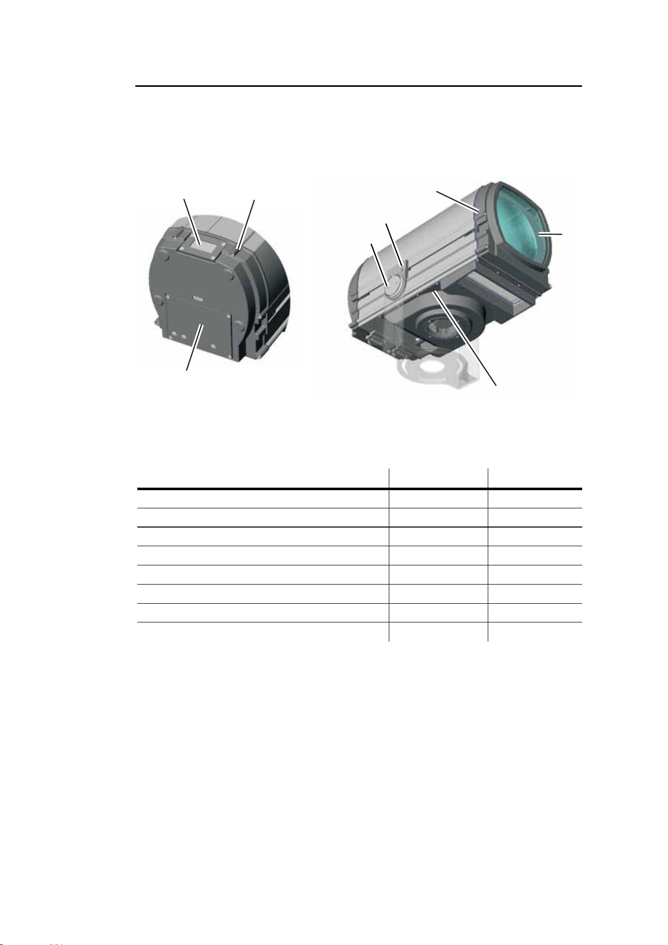
60 Exterior 1200 Wash user manual
8.4.3 Torque settings
The torque settings for the yoke screws as well as screws holding covers and part
numbers for the corresponding seals are as shown below.
To ensure that the Exterior 1200 Wash is waterproof and to avoid damaging threads, a
torque driver with a range from 2 Nm (1.5 ft.-lbs.) to 16 Nm (11.8 ft.-lbs.) must be used.
during service and adjustment.
Component Torque setting Seal P/N
A - Display cover 2 Nm (1.5 ft.-lbs.) 20620160
B - Rear cover 7 Nm (5.2 ft.-lbs.) 20620130
C - Connections box 2 Nm (1.5 ft.-lbs.) 20620150
D - Front cover 7 Nm (5.2 ft.-lbs.) 20620130
E - Front glass (screws inside luminaire) 2 Nm (1.5 ft.-lbs.) 20620140
F - Cooling fan housing 2 Nm (1.5 ft.-lbs.) No seal fitted
G - Tilt lock 16 Nm (11.8 ft.-lbs.) No seal fitted
H - Yoke slider 16 Nm (11.8 ft.-lbs.) No seal fitted
Table 3: Torque settings and seal part numbers
A B
C
D
D
E
E
F
F
G
H
Figure 17: Torque settings

Lamp maintenance 61
8.5 Lamp maintenance
8.5.1 Approved lamp
Important! The Exterior 1200 Wash is designed to use only the lamp specified below.
Installing any other model may cause damage to the luminaire that is not
covered by the product warranty.
Data subject to change. Refer to lamp manufacturer’s specifications for latest information.
8.5.2 Lamp life and monitoring lamp hours
A discharge lamp’s quartz bulb weakens over time, significantly increasing the risk of lamp
explosion. Always replace a discharge lamp before it reaches the limit of its average life
(see table above). In large installations, replacing all lamps at the same time will simplify
replacement schedules.
The Exterior 1200 Wash has built-in resettable counters that you can use to monitor the
number of hours the lamp has been used and the number of times the lamp has been
struck (started). The counters can be checked in the onboard control panel or using the
MUM application. Check the counter as necessary, and reset the luminaire’s Resettable
Lamp Hours and Resettable Lamp Strikes counters each time you install a new lamp
A. Checking and resetting the lamp life counters using the onboard control
panel
The onboard control panel displays the lamp hours and lamp strike counters in the Lamp
Status display every few seconds until you enter the control menus.
To reset the counters using the onboard control panel:
1. Open the Personality menu, navigate to the counters and press Enter to display.
2. To return the resettable lamp hours and lamp strikes counters to zero, select Reset
all counters, press Enter and confirm.
B. Checking and resetting the lamp life counters using MUM
To reset the counters:
1. Connect a PC and DABS1 adaptor to the Exterior 1200 Wash via the service port in
the connections compartment.
2. Power on the Exterior 1200 Wash and start the MUM application. The application will
automatically detect an Exterior 1200 Wash if it is powered on and correctly
connected. It will also retrieve the current settings on the luminaire and display them.
Lamp Average life Color temp. CRI (Ra8) Output
Philips MSD 1200 3000 hours 6000 K 80 92 000 lm
Table 4: Lamp specifications
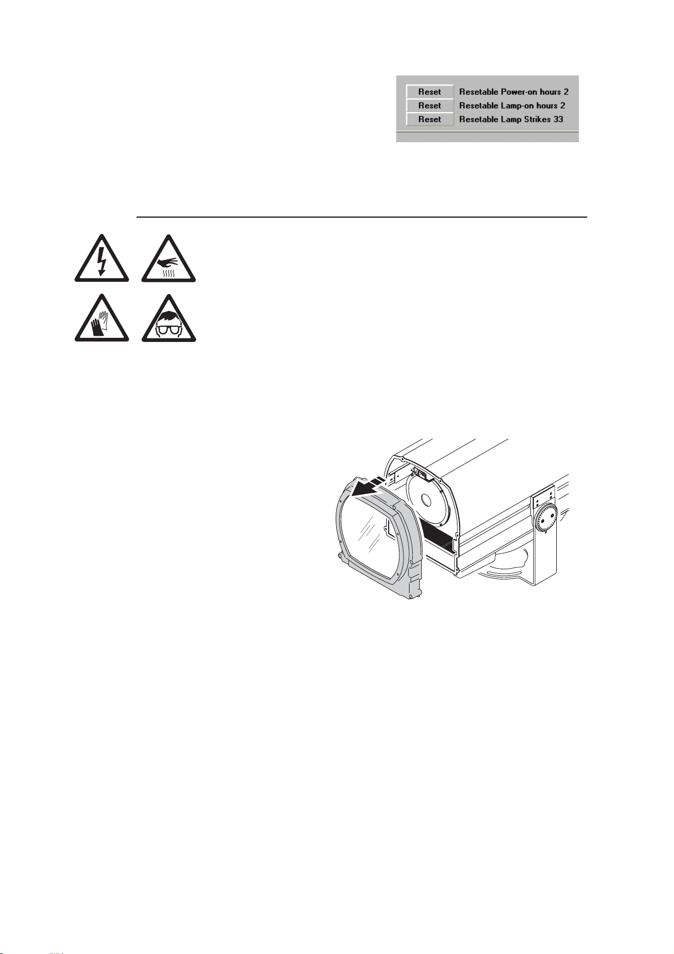
62 Exterior 1200 Wash user manual
3. Using MUM, click on the Fixture info
button.
4. The Resettable Lamp-on hours will be
displayed. Click on the Reset buttons
beside Resettable Lamp-on hours and
Resettable Lamp Strikes to return
these figures to zero.
8.5.3 Installing the lamp
Warning! Switch off the lamp, allow the luminaire to cool with
fans running for 20 minutes, then isolate it from AC power and
lock out power before servicing.
Wear safety glasses and gloves while installing or inspecting
the lamp.
To replace the lamp:
1. Cut lamp power, allow the luminaire to cool with fans running for 20 minutes, then
isolate it from AC power and lock out power.
2. See Figure 18. Loosen the
six Allen head screws
holding the front cover and
remove the cover and its
silicone seal. Avoid
damaging the seal during
removal. If you do not
remove the seal, you may
damage it and will make
access more difficult.
Figure 18: Removing the front cover and seal
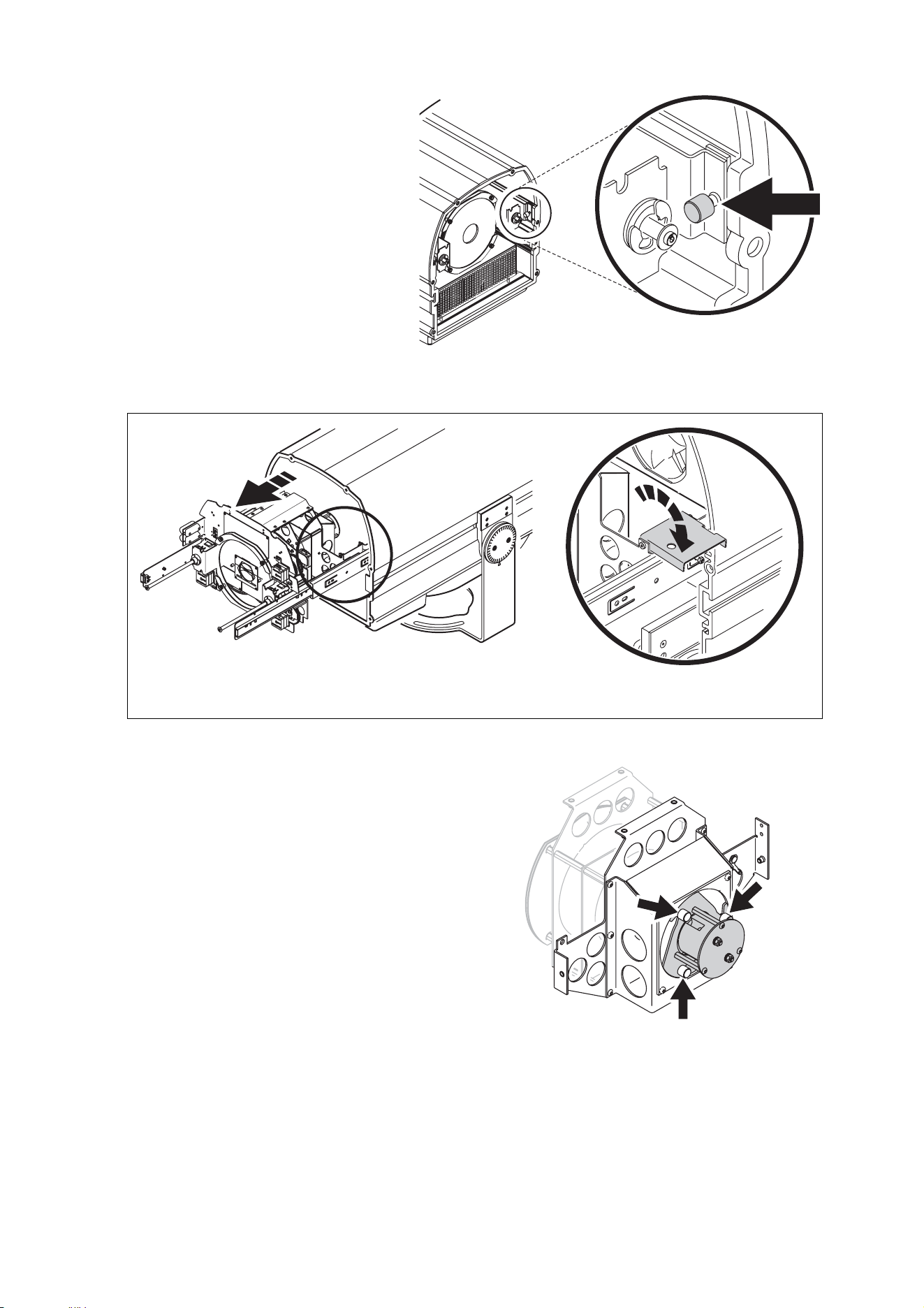
Lamp maintenance 63
3. See Figure 19. Pull out
the slider locks in the
sliders on each side at
the front of the housing.
4. Slide the lamp/effects
module out of the
housing, avoiding strain
on internal wiring. Note
that a lamp cutout
mechanism is activated
as soon as the module is
moved from its normal
position.
5. See Figure 20. Flip open the latch plate to lock the module in the out position.
6. See Figure 21. The lampholder is
at the rear of the effects modules.
Loosen, but do not remove, the
three Allen screws (arrowed)
holding the lampholder. To
release the lampholder, push it in
slightly towards the modules and
rotate it so that the holes in the
lampholder plate clear the Allen
screws, then gently pull the
lampholder clear. Avoid touching
or knocking the lamp against
other components.
Figure 19: Slider lock
Latch plate
Figure 20: Slider latch plate
Figure 21: Lampholder screws
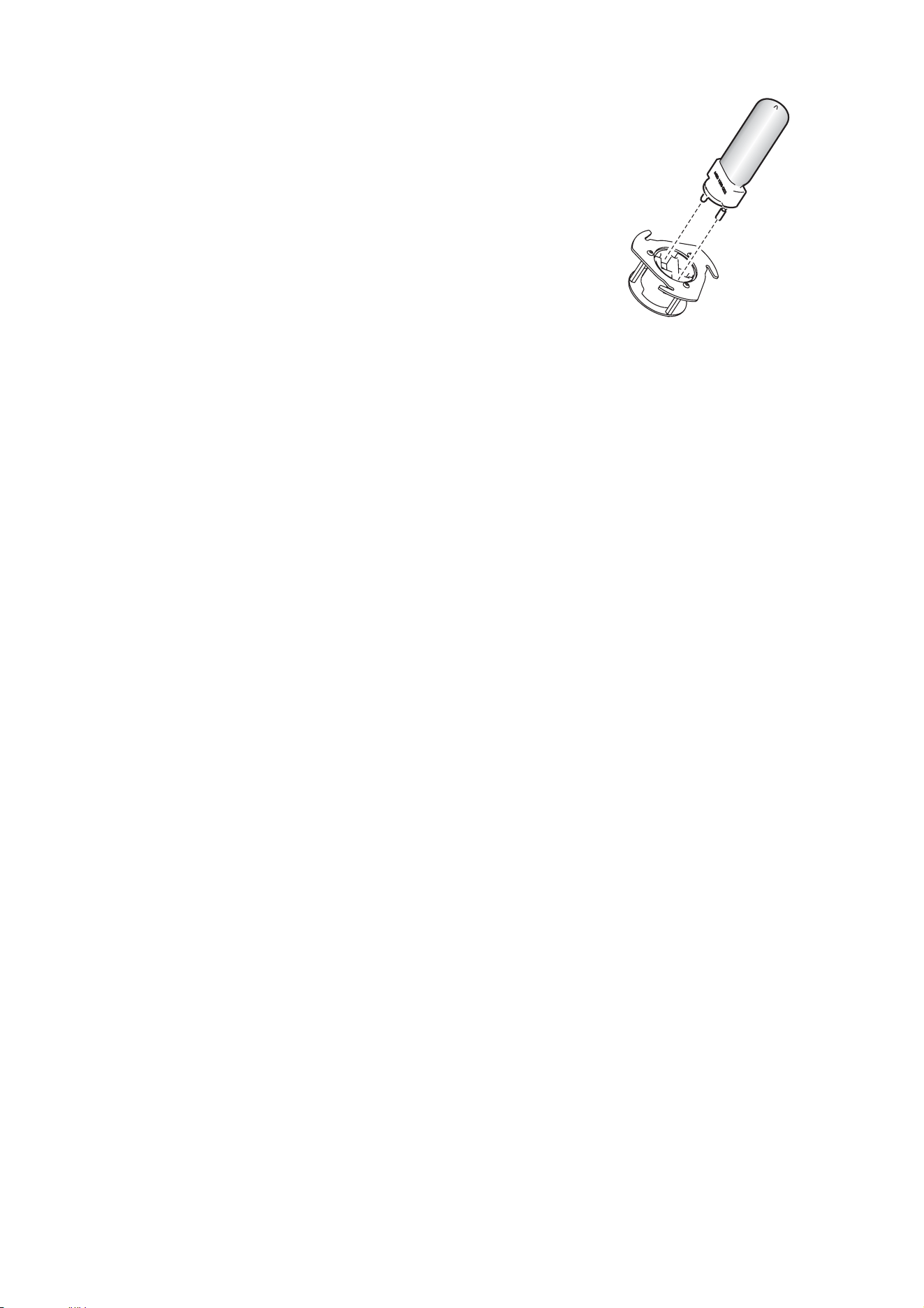
64 Exterior 1200 Wash user manual
7. If replacing an old lamp, remove it from the socket.
8. The new lamp’s glass bulb must be perfectly clean. Do
not touch it with your fingers. Clean it using the wipe
supplied with the lamp. A clean, lint-free cloth wetted
with 99.9% isopropyl alcohol may also be used.
9. Holding the new lamp by its ceramic base, insert it
firmly and squarely into the lamp socket.
10. Re-insert the lampholder in its original position, pushing
and twisting it to lock it in place on the three Allen
screws. Check that lamp wiring is also in its original
position.
11. Tighten the lampholder screws.
12. Push the effects/lamp module back into the housing.
Make sure that the slider locks click into place to ensure
that the module is correctly positioned and the lamp cutout mechanism is deactivated.
13. Before reinstalling the front cover, check the condition of the seal. Replace with a new
item if the seal is torn, cracked or brittle.
14. Place the front cover and seal firmly against the housing. Adjust the straight sides of
the seal so that they stick out a little, just enough so that you can feel the seal when
you run a finger across the joint.
15. Cross-tighten the cover screws, tightening gradually to a torque of 7 Nm (5.2 ft.-lbs.).
At this torque, the seal will be compressed by about one-third.
16. Reapply power and return the resettable lamp hours and lamp strikes counters to zero.
See "8.5.2: Lamp life and monitoring lamp hours" on page 61.
Lamp alignment is factory-set. If after installing a new lamp the Exterior 1200 Wash has a
noticeable hot-spot or dark area in the centre of the beam, or if the brightest part of the
beam is significantly off-center, the lamp may need to be realigned. Please contact your
Martin Architectural supplier for assistance.
8.6 Installing color filters
As standard, the Exterior 1200 Wash is supplied with CTC (5500 K to 3400 K), red, green
and blue dichroic color filters installed in the color wheel. Filters can be replaced if other
colors are required.
The Exterior 1200 Wash also features a holder for a permanent filter. A CTC filter can be
installed in this holder to match the color temperature of the light output precisely with
other luminaires.
Filters can be ordered from Martin Architectural.
For best performance, install filters with the coated surface facing away from the lamp.
Filters must be perfectly clean and free of grease when installed. Wear clean cotton
gloves to avoid contaminating filters with oil from your fingers. If necessary, clean filters
with a soft lint-free cloth wetted with 99.9% isopropyl alcohol.
To install a color filter:
1. Open the luminaire and slide the effects module out of the luminaire housing as
described in "8.5.3: Installing the lamp" on page 62.
Figure 22: Lamp socket
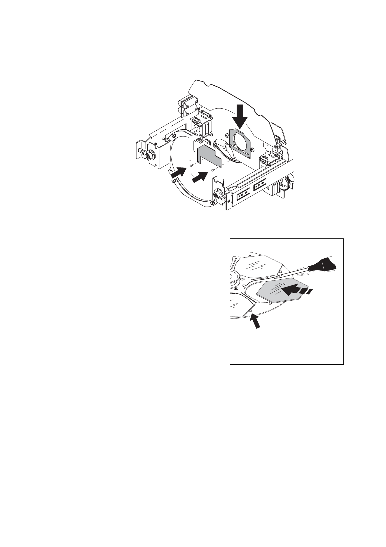
Installing color filters 65
2. See Figure 23. To install a permanent filter, slide the filter fully into the filter holder (B)
so that it is held securely by the clip.
3. To install a filter on the color wheel, remove the two Torx 10 retaining screws (A) from
the filter access plate and remove the plate.
4. To remove a filter, use a small flathead
screwdriver to lift the filter support leaves on
the color wheel. Lift the filter slightly and slide
it out.
5. To install a filter, lift the filter support leaves
and slide the new filter into place on the color
wheel. Make sure that it is held securely by
the retaining lugs (C in Figure 24).
6. Reinstall the filter access plate.
7. Slide the effects module back into the
luminaire housing and close the luminaire as
described in "8.5.3: Installing the lamp" on
page 62 before reapplying power.
B
A
A
Figure 23: Filter replacement
Figure 24: Installing a filter
C
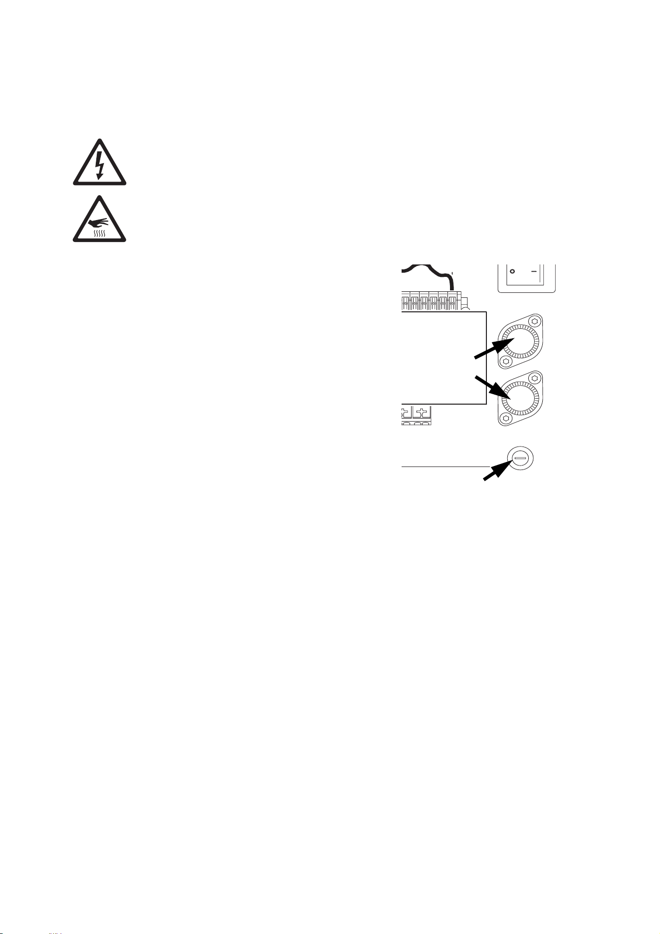
66 Exterior 1200 Wash user manual
8.7 Replacing fuses
Warning! Switch off the lamp, allow the luminaire to cool with fans running
for 20 minutes, then isolate it from AC power and lock out power before
replacing a fuse.
The Exterior 1200 Wash is protected by two 15 amp slow blow main fuses (P/N
05020050) located in fuseholders behind the rear cover plate. One fuse protects the
connection labelled “Live 1”, and one protects “Live 2”. If the luminaire fails to respond
when power is applied, one of these may have blown.
To replace a main fuse:
1. Switch off the lamp, allow the luminaire to cool
with fans running for 20 minutes, then isolate it
from AC power and ensure that power cannot be
reconnected accidentally.
2. Remove the rear cover plate as described in
"3.1.4: Connections compartment access" on
page 18.
3. The two main fuses are located in fuseholders in
the connections compartment. Use a torx
screwdriver to open the fuseholders and remove
the fuses.
4. Replace the defective fuse with one of the same
size and rating. Replace the fuseholders.
5. Reinstall the cover plate as described in "3.1.4:
Connections compartment access" on page 18.
If neither of the main fuses are defective, check and if necessary replace the 10 amp slow
blow main PCB low-voltage fuse (P/N 05020025) with one of the same type and rating.
50
60
277
250
240
230
220
208
200
Hz Setting
Volt Setting
Volt Setting
SERVICE
DMX
OUT
DMX
IN
1
++--
23456
Ground
Neutral
Live 1Live
1
Live 2
Live
2
MAINS
MAIN
FUSE
PCB
Live 2
Live 2
Fuse
Live 1
Live 1
Fuse
Main fuses
Main PCB fuse
Figure 25: Fuses
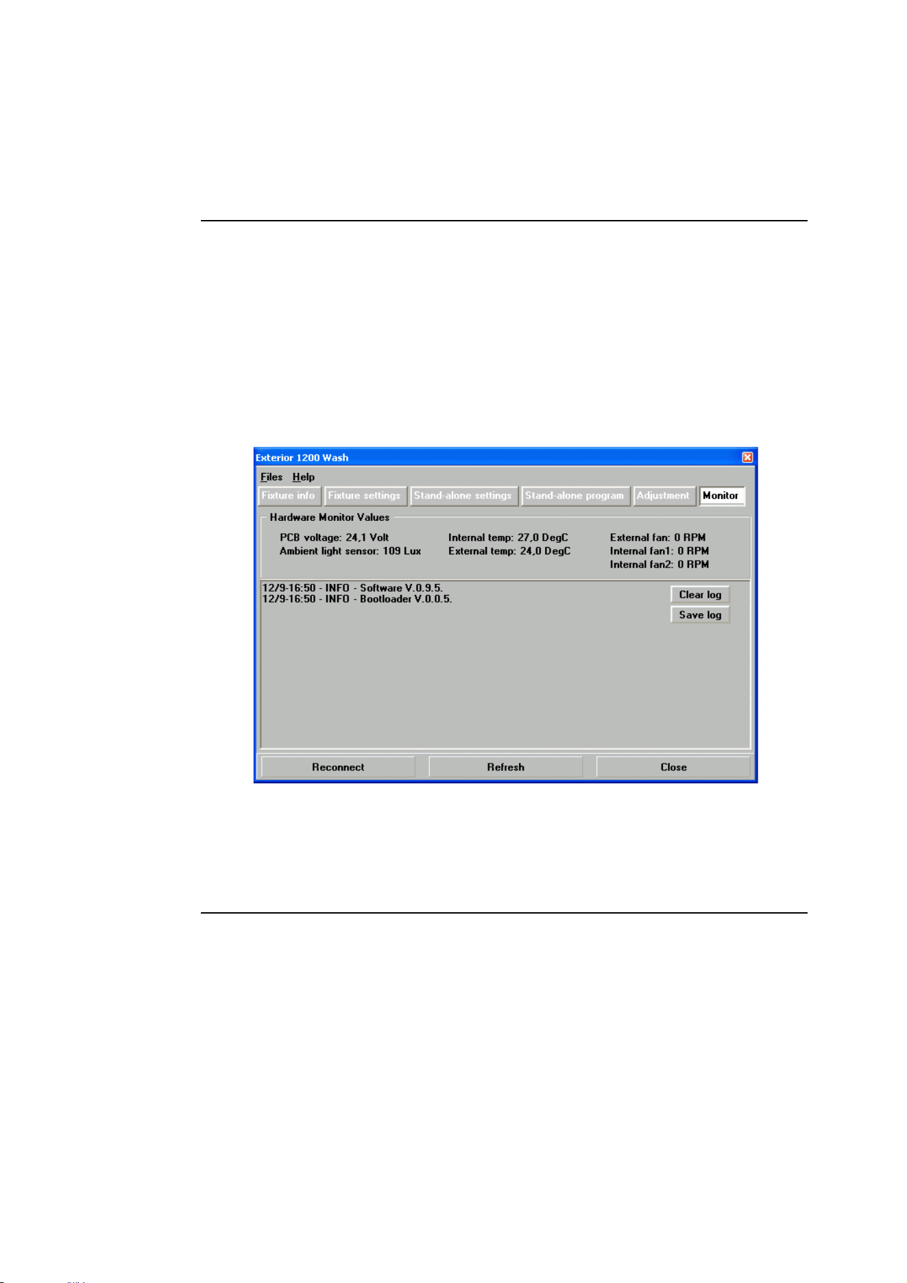
Software-based service functions 67
8.8 Software-based service functions
8.8.1 Adjustment and monitoring
MUM, the MP-2 Uploader and the onboard control panel all contain an Adjustment
function. This is a tool for mechanical adjustment and effect calibration, and is for use by
Martin Global Service and its authorized agents.
The Monitor function in MUM and the onboard control panel is for use primarily by
Martin Global Service and its authorized agents, but can be a means of obtaining
information that is useful for problem diagnosis.
• To view monitoring information in MUM, connect the luminaire to MUM via a DABS1
interface as described in "5.1.1: Setting up a luminaire with a PC and MUM" on page 33,
then click on the Monitor button. As well as hardware monitoring information, software
and bootloader version details are displayed.
• To view monitoring information in the onboard control panel, scroll through the Info
menu.
8.8.2 Restoring factory defaults
The Exterior 1200 Wash factory default settings can be restored, if required.
Restoring using MUM
The most secure way of restoring factory defaults using MUM is to download the current
luminaire software version from the Martin website and upload it to the luminaire using
one of the upload options in the Files menu.

68 Exterior 1200 Wash user manual
Restoring via an MP-2
To restore factory defaults using an MP-2 Uploader, use the Personality → Factory
default command.
Restoring via the onboard control panel
To restore factory defaults using the onboard control panel, use the Personality →
Factory default command.
8.8.3 Software updates
The most recent software versions for all Martin Architectural products are available free
of charge from the Support area of the Martin website at http://www.martin.com
If the Exterior 1200 Wash software needs to be updated, the software can be downloaded
and then installed using a Martin MP-2 Uploader or a PC with Martin Software Uploader
shareware (also available free of charge from the Martin website). The PC must be
connected to the Exterior 1200 Wash via a hardware interface. The following hardware
interface devices are currently supported:
• DABS1 PC/luminaire hardware interface
• ShowDesigner PCI DMX Interface Card (2048 channel version)
• LightJockey PCI DMX Interface Card (512 and 2048 channel versions)
• LightJockey PCMCIA DMX Interface
• LightJockey 4064 ISA DMX Interface Card (DJ and Club versions)
Intermediate control systems such as the Martin Lighting Director (MLD) and the Martin
Matrix must be bypassed when updating luminaire software via the data link because they
do not relay the update code correctly.
Before updating software, read the release notes to familiarize yourself with any changes
in functionality or any special instructions.
Some software releases may require a boot mode upload or a boot sector update. If so,
contact your Martin Architectural supplier for assistance.
Software updates (DMX/Auto mode upload)
To update software, connect an upload device either to the data input of the luminaire via
the DMX data link or to the RJ-45 service port located behind the rear cover plate, and
perform a DMX mode upload as described in the upload device’s documentation. If
uploading via the DMX data link, there is no need to isolate Exterior 1200 Wash luminaires
from other types of luminaires on the link.
When the upload is completed (and when booting up) the Exterior 1200 Wash performs a
check-sum test of the memory and then resets.
In the unlikely event that a software upload is interrupted, the luminaire must be powered
off for at least 10 seconds and then powered on again to force a check-sum test. You can
then repeat the DMX mode upload. If an error occurs during subsequent uploads and the
luminaire does not reset, data may have been interrupted or corrupted during
transmission. A boot mode upload will almost certainly rectify this problem.
Important! Boot mode uploads must be carried out by Martin Global Service or its
authorized agent. If you suspect that a boot mode upload is necessary,
please contact your Martin Architectural supplier for assistance.

8.9 Troubleshooting
Problem Probable cause(s) Remedy
No response from
luminaire when power is
applied.
No power to luminaire. Check power cables.
Main or low-voltage fuse
blown.
Replace fuse.
Secondary fuse(s) blown
(located on PCB).
Refer to Martin Architectural.
Luminaire resets when
power applied but does
not respond correctly to
DMX controller. LED 2
lights steady green.
Incorrect DMX addressing.
Check luminaire addressing on
controller. If no error found, check
luminaire’s DMX address setting.
Luminaire resets when
power applied but does
not respond correctly to
DMX controller. LED 2
does not light steady
green.
Bad data link connection.
Inspect cables and correct poor
connections and/or broken cables.
Data link not terminated.
Insert DMX termination resistor in data
output of last luminaire on each branch of
the data link.
Luminaire resets when
power applied but does
not respond correctly to
DMX controller. LEDs
flash red and green.
Defective luminaire.
Bypass luminaires on the data link one at
a time until normal operation is regained.
Electronic or mechanical
failure.
Refer to Martin Architectural.
Luminaire software corrupted.
Upload new software. If luminaire
repeatedly fails to reset correctly, refer to
Martin Architectural for boot mode
upload.
Luminaire cuts out
intermittently, especially
in hot weather.
Luminaire temperature too
high: thermal cutout shutting
down power to avoid
overheating.
Stop using luminaire. Inspect for dirt
buildup and clean if necessary.
If luminaire is clean or if problem
reoccurs, stop using luminaire and refer
to Martin Architectural.
No light output.
Lamp has been in use and is
too hot to restrike.
Allow to cool for 8 minutes before
attempting to restrike.
Lamp defective or worn out. Replace lamp.
Lamp cutout inside front cover
not correctly deactivated.
Open front cover. Make sure that left-
hand slider lock presses cutout switch.
Power settings do not match
local AC voltage and
frequency.
Disconnect luminaire and open rear
cover. Check jumper lead settings and
correct if necessary.
Temperature or fans error
Check display for error message. Check
for dirt buildup. Check that ambient
temperature does not exceed maximum.
Refer to Martin Architectural.
Lamp life unexpectedly
short (note that 3000
hours is average life, not
minimum).
Defective lamp. Replace lamp.
Strain on lamp or excessive
lamp strikes.
Always allow lamp to fully warm up for
five minutes before turning off.
Leave lamp powered and use intensity
command to reduce light output to zero if
only cutting light output for short periods.
Leave power applied for at least 8
minutes after switching off lamp to allow
cooling fans to reduce temperature.

70 Exterior 1200 Wash user manual
8.10Accessories
This section lists the optional accessories available for the Exterior 1200 Wash. You can
find an updated list on the Martin Architectural website at http://www.martin-
architectural.com.
Installation instructions are included with all accessories and can also be downloaded
from the Support area of the Martin Architectural website.
Beam shaper lens
A beam shaper lens is available as an optional accessory for Exterior 1200 Wash Narrow
and Medium beam angle models. The beam shaper flattens and widens the beam into an
elliptical shape. It can be rotated manually to adjust the axis of the beam so that a tall
vertical or wide horizontal beam is projected.
Custom color filters
A range of dichroic color filters, including various CTC filters, is available from Martin
suppliers.
5500-4200 K CTC kit
The Color Temperature Control (CTC) kit consists of a dichroic color filter that can be
permanently installed in the lamp/effects module. With the filter fitted, color temperatures
are reduced, giving warmer colors but with slightly reduced light output. The shift in color
temperatures corresponds to a reduction from 5500 to 4200 K.
Snoot/barndoor kit
The snoot/barndoor kit consists of plates that can be installed around the Exterior 1200
Wash front glass using supplied hardware in order to limit beam angle and control light
overspill or glare.

Accessories 71
Section 9. Reference
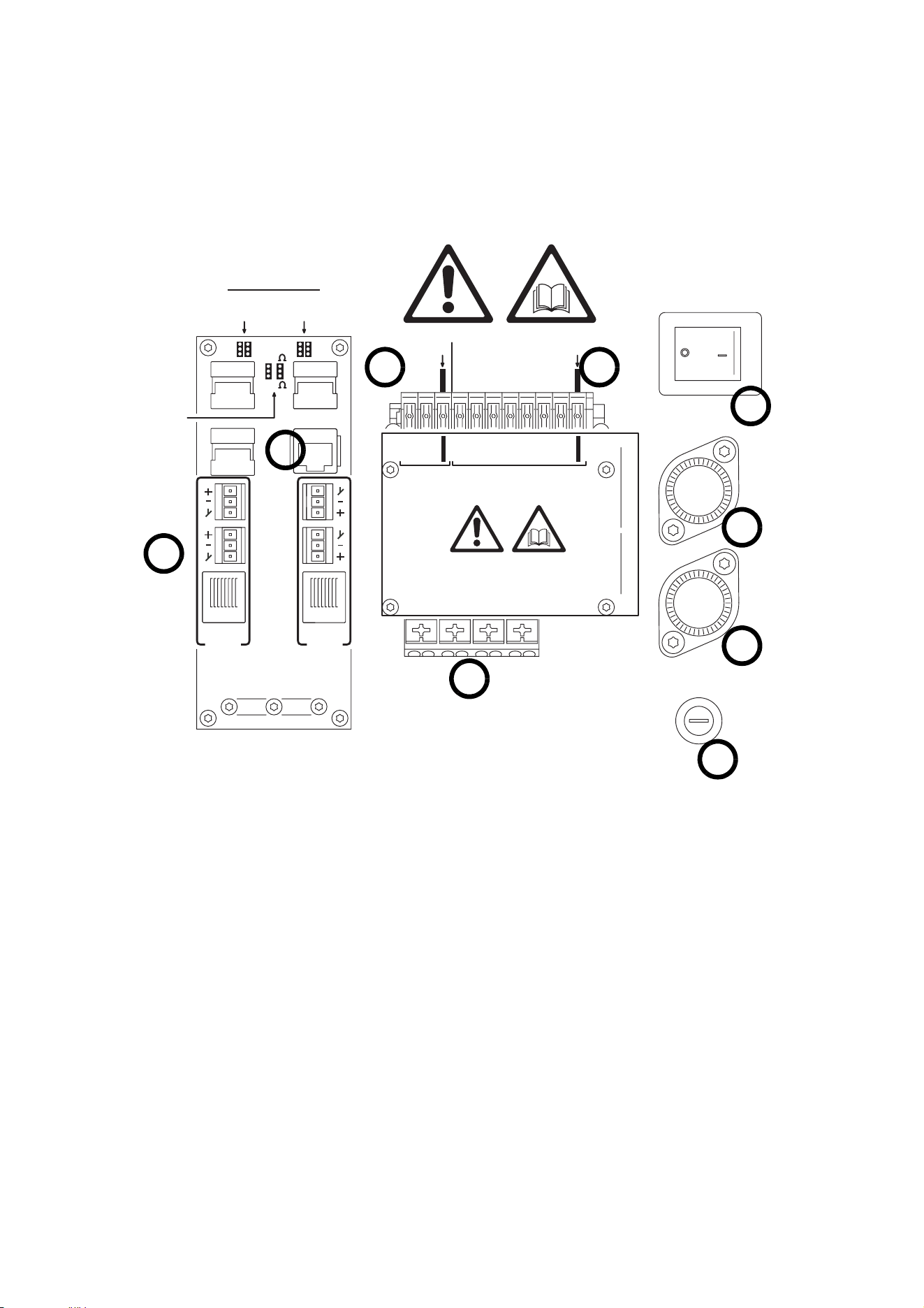
72 Exterior 1200 Wash user manual
9.1 Connections compartment
The connections compartment behind the rear cover plate contains the elements
illustrated below:
Data
2
Data
1
Termination
Termination
Data
set 2
set 2
Data
set 1
set 1
50
60
277
250
240
230
220
208
200
DMX
OUT
MAINS
MAIN
FUSE
PCB
Hz Setting
Hz Setting
Volt Setting
Volt Setting
Live 2
Live 2
Fuse
Live 1
Live 1
Fuse
Ground
Neutral
Live 1
Live
1
Live 2
Live
2
50
60
277
250
240
230
220
208
200
Hz Setting
Hz Setting
Volt Setting
Volt Setting
Service
RJ45
DMX
IN
Cable
impedance
100
120
B
A - Service port (RJ-45 socket)
B - AC power frequency setting jumper
C - AC power voltage setting jumper
D - Main power on/off switch
E - AC power connection terminals
F - DMX connection terminals
G - Main fuseholders
H - PCB (low voltage) fuseholder
A
C
D
G
G
H
E
F
LED status messages 73
9.2 LED status messages
The three-digit version number (major.minor.build) of the installed software is displayed by
the LEDs on power up. The number of:
• Red flashes in LED 1 indicates the major number, followed by,
• Green flashes in LED 2 to indicate the minor number, followed by,
• Red flashes in LED 2 to indicate the build number (only used for beta releases)
For example, if the software version is 1.3.0, LED 1 flashes red once and LED 2 flashes
green three times.
Appearance Message, LED 1 Message, LED 2
Steady green Effects OK Data OK.
Steady red - Invalid data/no data
Steady yellow
Waiting for upload, or
upload in progress
Waiting for upload, or
upload in progress
Flashing yellow Reset in progress Reset in progress
Flashing red &
green
See message in display
or contact a service
technician
Off - No data detected
Table 5: LED status messages
74 Exterior 1200 Wash user manual
9.3 Onboard control panel menus
Menu Options Notes
Fixture address 1 - 503 Set the luminaire’s DMX address
Standalone
Enable SA Enable stand-alone operation
SA
Execution
Single
Set luminaire to independent stand-
alone operation
Master
Set luminaire as master in master/
client synchroniz
ed stand-alone
operation
Synchronized
Set luminaire as client in master/client
sync
hronized stand-alone operation
Personality
DMX Lamp off
When enabled, allows lamp to be
turned off via DMX
DMX Reset
When enabled, allows luminaire to be
reset via DMX
Auto lamp on
When enabled, turns lamp on as soon
as power is applied to luminaire
Fan regulation
When enabled, cooling fan speed is
temperature-regulated (when
disabled, fans run at full speed)
Display Errors
When enabled, gives priority in the
display to error messages
Setup ¿C/¿F
Set temperature readouts to
Centigrade or Fahrenheit
Set backlight level
Set brightness of display backlighting
(0 - 100)
Set clock Set real-time clock
Reset counters Reset all counters
Load Factory Default
Return all luminaire settings to factory
default
Info Version
Displays main luminaire software and
control panel display software
versions
Manual
Fixture reset Reset luminaire
Set lamp On Turn on lamp
Set lamp Off Turn off lamp
Set Intensity Set shutter position (1 - 255)
Set Cyan Set cyan position (1 - 255)
Set Magenta Set magenta position (1 - 255)
Set Yellow Set yellow position (1 - 255)
Set Colorwheel Set color wheel position (1 - 255)
Set Zoom Set zoom position (1 - 255)
Utility
(press for 3
seconds to activate
menus)
Adjust
Fixture reset Reset luminaire
Set lamp On Turn on lamp
Set lamp Off Turn off lamp
Adjust effects
All – Zoom: open or close effects (for
adjustment and test purposes)
Force Upload
Prepare luminaire for boot mode
software upload
MP-2 control menus 75
9.4 MP-2 control menus
Menu Options Notes
Fixture address 1 - 503 Set the luminaire’s DMX address
Stand Alone
Enable SA Enable/disable stand-alone operation
SA
Execution
Single
Set luminaire to independent stand-
alone operation
Master
Set luminaire as master in
master/client synchronized stand-
alone operation
client
Set luminaire as client in master/client
sy
nchronized stand-alone operation
Light
Level
Enable
Enable ambient light level triggering
of stand-alone operation
Level Enter value to set triggering light level
Capture
Set current ambient light level as
triggering light level
Timer
Enable Enable timer-controlled operation
Timer 1
Set start and stop times for timer 1
(first daily operation period)
Timer 2 Set start and stop times for timer 2
Program
Intensity Set intensity
Cyan Set amount of cyan
Magenta Set amount of magenta
Yellow Set amount of yellow
Color wheel Select filter on color wheel
Zoom Set zoom value
Fade time
Pick table lets you select a fade
time from Snap (instant) to
2 m 0 s (two minutes)
Custom lets you define a custom
fade time by entering values for
hours, minutes and seconds
Wait time
Pick table lets you select a wait
time from 0s (scene fades to the next
with no wait time) to 2 m 0 s (scene is
held for two minutes fading to the
next)
Custom lets you define a custom wait
time
Add scene
Save settings in a new scene at the
end of the current sequence of
scenes
Next scene Step to the next scene
Previous scene Step to the previous scene
Store scene Save settings in the current scene
Insert scene
Add settings in a new scene
immediately before the current scene
Delete scene Delete the current scene
Clr all scenes Clear all scenes from memory
Run program Run the programmed light show

76 Exterior 1200 Wash user manual
Adjust
Reset Reset luminaire
Lamp on Turn on lamp
Lamp off Turn off lamp
Real time clock Set the 24-hour on-board clock
All effects Open or close all effects
Intensity Open or close shutter
Cyan Open or close cyan filter
Magenta Open or close magenta filter
Yellow Open or close yellow filter
Color wheel Select color wheel position
Zoom Move zoom to near or far position
Personality
DMX Lamp off
When enabled, allows lamp to be
turned off via DMX
DMX Reset
When enabled, allows luminaire to be
reset via DMX
Auto lamp on
When enabled, turns lamp on as soon
as power is applied to luminaire
Display Errors
When enabled, gives priority in the
display to error messages
Fan regulation
When enabled, cooling fan speed is
temperature-regulated (when
disabled, fans run at full speed)
Setup ¿C/¿F
Set temperature readouts to
Centigrade or Fahrenheit
Set backlight level
Set brightness of display backlighting
(0 - 100)
Factory default
Return all luminaire settings to factory
default
Reset counters Reset all counters
Version X.X
Displays currently installed luminaire
software version
Menu Options Notes
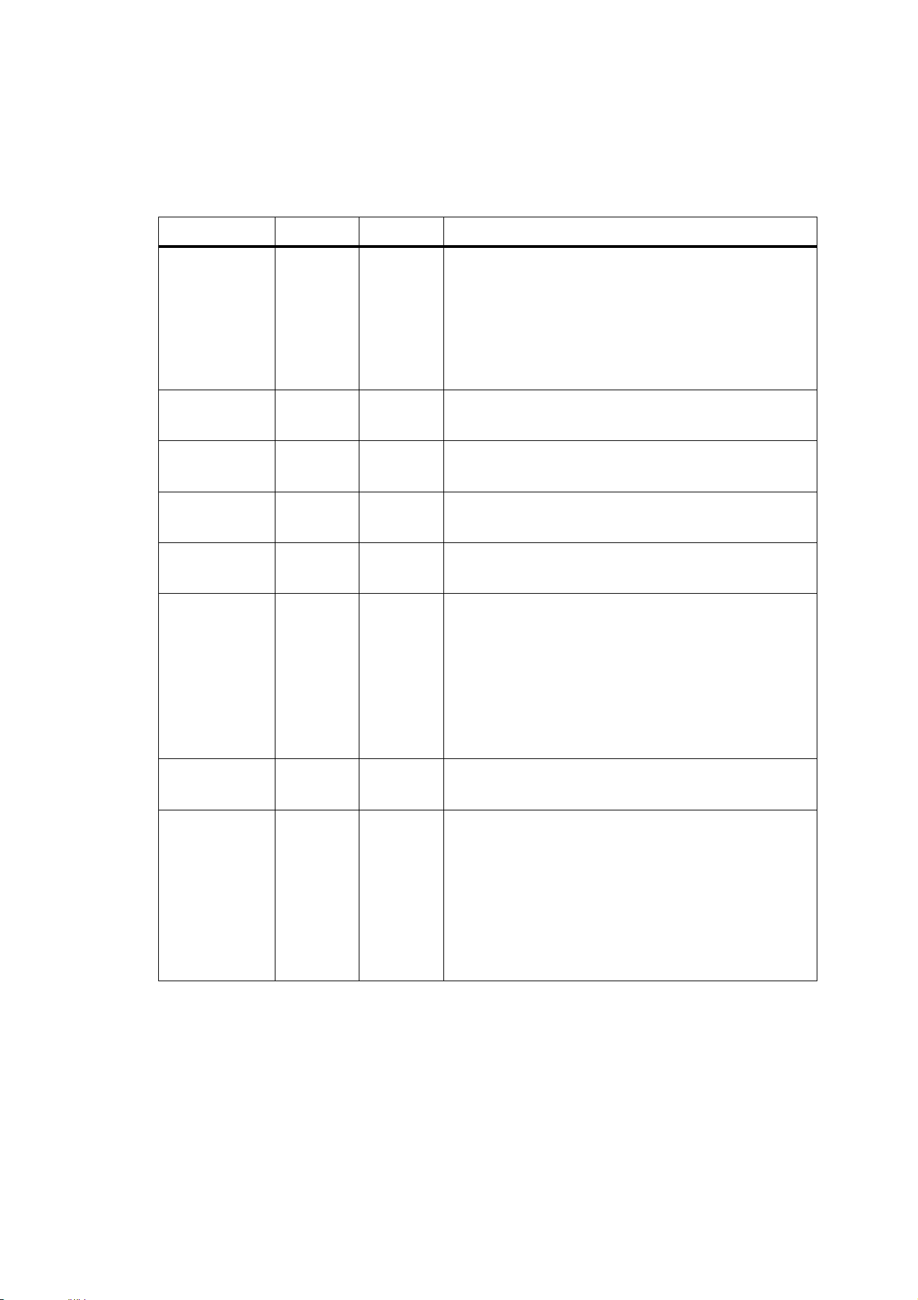
DMX protocol 77
9.5 DMX protocol
(1)
If DMX reset without confirmation is disabled in the control menus (Personality →
DMX Reset), the Exterior 1200 Wash can still be reset via DMX if confirmation is given by
setting channels 3 (cyan), 4 (magenta) and 5 (yellow) to a value of 230 - 232.
(2)
If DMX lamp off without confirmation is disabled in the control menus (Personality
→ DMX Lamp off), the lamp can still be powered off via DMX if confirmation is given by
setting channels 3 (cyan), 4 (magenta) and 5 (yellow) to a value of 230 - 232.
DMX channel Value Percent Function
1
0 – 208
208 - 217
218 - 227
228 - 237
238 - 247
248 - 255
0 - 81
81 - 85
85 - 87
89 - 93
93 - 97
97 - 100
Reset, lamp on/off
Reserved: selecting this value has no effect
Reset
(1)
Reserved: selecting this value has no effect
Lamp power on
Reserved: selecting this value has no effect
Lamp power off: value must be held for 5 seconds
(2)
2
0 - 255 0 - 100
Intensity
Intensity 0 → 100%
3
0 - 255 0 - 100
Cyan
White → cyan
4
0 - 255 0 - 100
Magenta
White → magenta
5
0 - 255 0 - 100
Yellow
White → yellow
6
0 - 9
10 - 19
20 - 29
30 - 39
40 - 49
50 - 255
0 - 3
4 - 7
8 - 11
12 - 15
16 - 18
19 - 100
Color Wheel
Stepped Scroll
Color 1 - White (open)
Color 2 - CTC
Color 3 - Red
Color 4 - Green
Color 5- Blue
Reserved: selecting this value has no effect
7
0 - 255 0 - 100
Zoom (Narrow and Medium models)
Wide → narrow
8
0 - 2
3 - 245
246 - 255
0 - 2
3 - 245
246 - 255
0 - 1
2 - 95
96 - 100
0 - 2
3 - 245
246 - 255
Effects (intensity, CMY and zoom) speed
Tracking mode
Vector mode fast → slow
Reserved: selecting this value has no effect
Color wheel speed
Tracking mode
Vector mode fast → slow
Reserved: selecting this value has no effect

Exterior 1200 Wash specifications
Physical
Length........................................................................................................................................860 mm (33.9 in.)
Width including mounting yoke..................................................................................................448 mm (17.6 in.)
Height including mounting yoke.................................................................................................620 mm (24.4 in.)
Weight........................................................................................................................................... 68 kg (150 lbs.)
EPA (Effective Projected Area) .................................................................................................0.6 m2 (6.5 sq. ft.)
Lamp
Type ...................................................................................................................................... 1200 W metal halide
Approved model.........................................................................................................................Philips MSD 1200
Lamp socket ................................................................................................................................................... G22
Control ..................................................................................................................Automatic and/or remote on/off
Dynamic Effects
Color mixing............................................................................................Independently variable continuous CMY
Cyan ........................................................................................................................................................0 - 100%
Magenta...................................................................................................................................................0 - 100%
Yellow.......................................................................................................................................................0 - 100%
Color wheel...............................................Red, green, blue, 5500 - 3400 K CTC (as standard) and white (open)
Dimmer ....................................................................................................................................................0 - 100%
Zoom, Narrow model, fresnel optics (one-tenth peak angle)...................................................................14° - 31°
Zoom, Medium model, fresnel optics (one-tenth peak angle)..................................................................20° - 50°
Control and Programming
Control options ...........................................................................DMX, stand-alone, synchronized (master
/client)
DMX channels ..................................................................................................................................................... 8
DMX address setting .................................................MUM (Multi-Utility Manager), MP-2, onboard control panel
Stand-alone programming ............................................................................. MUM, MP-2, onboard control panel
Stand-alone trigger options ........................................................................... Internal timer and light-level sensor
Stand-alone memory .............................................................................................................................20 scenes
Protocol .................................................................................................................................... USITT DMX-512A
Receiver.....................................................................................................................................................RS-485
Photometric Data
Narrow, zoom at spot position
Efficiency .................................................................................................................................................31%
Half-peak angle............................................................................................................................................8°
Total output ..................................................................................................................................... 28 600 lm
Narrow, zoom at flood position
Efficiency .................................................................................................................................................31%
Half-peak angle..........................................................................................................................................16°
Total output ..................................................................................................................................... 28 200 lm
Narrow, zoom at spot position, with beam shaper lens accessory
Efficiency .................................................................................................................................................29%
Half-peak angle, C
0
....................................................................................................................................20°
Half-peak angle, C
90
....................................................................................................................................9°
Total output ..................................................................................................................................... 26 400 lm

Narrow, zoom at flood position, with beam shaper lens accessory
Efficiency .................................................................................................................................................27%
Half-peak angle, C
0
....................................................................................................................................25°
Half-peak angle, C
90
..................................................................................................................................17°
Total output ..................................................................................................................................... 24 400 lm
Medium, zoom at spot position
Efficiency .................................................................................................................................................22%
Half-peak angle..........................................................................................................................................12°
Total output ..................................................................................................................................... 20 200 lm
Medium, zoom at flood position
Efficiency .................................................................................................................................................31%
Half-peak angle..........................................................................................................................................29°
Total output ..................................................................................................................................... 28 800 lm
Wide
Efficiency .................................................................................................................................................38%
Half-peak angle..........................................................................................................................................44°
Total output ..................................................................................................................................... 34 500 lm
Very wide
Efficiency .................................................................................................................................................37%
Half-peak angle..........................................................................................................................................48°
Total output ..................................................................................................................................... 33 700 lm
Construction
Housing ................................................................................................................................................. Aluminum
Finish .............................................................................................................................................Clear anodized
Front glass.................................................................................................................6 mm, anti-reflection coated
Color filters .............................................................................................................. 1.2 mm, dichroic, hexangular
Protection factor..........................................................................................UL wet location, main enclosure IP65
Installation
Orientation ........................................................................................................... Any (air intake must face down)
Minimum distance to combustible materials........................................................................................1 m (40 in.)
Minimum distance to illuminated surfaces...........................................................................................1 m (40 in.)
Minimum clearance around heat exchanger cowling...................................................................135 mm (5.5 in.)
Minimum clearance from top of luminaire to building member .......................................................150 mm (6 in.)
Minimum clearance from center of fixture to side building member .............................................400 mm (16 in.)
Minimum center-to-center distance in side-by-side installation .................................................800 mm (31.5 in.)
Connections
Power cable entry ...................................................................................................................... IP68 cable gland
Power connection ..................................................................................................................... Quick connectors
Data cable entry ........................................................................................................................ IP68 cable gland
Data connection.................................................................................. RJ-45 or screw terminal/quick connectors
Electrical
AC power ..............................................................................200/208/220/230/240/250/277 V nominal, 50/60 Hz
Main fuse ................................................................................................................................... 15 AT (slow blow)
Ballast......................................................................................................................................................Magnetic

Typical power and current*
200 V, 50 Hz ...................................................................................................................1380 W, 7.0 A, PF 0.975
200 V, 60 Hz ...................................................................................................................1405 W, 7.3 A, PF 0.960
208 V, 60 Hz ...................................................................................................................1417 W, 7.1 A, PF 0.958
220 V, 50 Hz ...................................................................................................................1373 W, 6.4 A, PF 0.973
230 V, 50 Hz ...................................................................................................................1365 W, 6.1 A, PF 0.973
240 V, 50 Hz ...................................................................................................................1370 W, 5.9 A, PF 0.973
250 V, 50 Hz ...................................................................................................................1364 W, 5.6 A, PF 0.972
277 V, 60 Hz ...................................................................................................................1417 W, 5.4 A, PF 0.956
*Figures listed are typical, not maximum. Measurements taken at nominal voltage. Allow for +/- 10%
variation. PF = Power factor.
Thermal
Maximum ambient temperature (Ta)...............................................................................................45° C (113° F)
Minimum ambient temperature (Ta)................................................................................................- 20° C (- 4° F)
Maximum surface temperature, steady state, Ta=45° C................................................................. 90° C (194° F)
Total heat dissipation (calculated, +/- 10%)......................................................................................4950 BTU/hr.
Cooling ........................................................................Forced air, integrated air/air heat exchanger, IP65 barrier
Approvals
US safety (pending) .....................................................................................................UL 1598
Canadian safety (pending).................................................................CSA C22.2 No. 250.0-00
EU safety ........................................................................................EN 60 598-1, EN 61 347-1
EU EMC.......................................................................EN 55 015, EN 55 103-1, EN 61 000-3
Included Items
Philips MSD 1200 lamp .................................................................................................................. P/N 97010313
Two M16 x 1.5 IP68 cable glands, metal, cable diameter 5.5 - 10 mm (0.22 - 0.39 in.) ................. P/N 13102030
One M20 x 1.5 IP68 cable gland, metal, cable diameter 8 - 13 mm (0.32 - 0.5 in.) ....................... P/N 13102090
Four M16 cable entry blanking plugs (installed), metal, with neoprene seals ................................ P/N 13102050
Two M20 blanking plugs (installed), metal, with neoprene seal...................................................... P/N 13103030
Two main fuses, 15 AT (installed) ................................................................................................... P/N 05020050
PCB fuse, 10 AT (installed)............................................................................................................. P/N 05020025
User manual ................................................................................................................................... P/N 35000177
Accessories
Elliptical beam shaper lens............................................................................................................. P/N 91610081
Snoot/barndoor kit .......................................................................................................................... P/N 91611257
5500-4200 K CTC filter................................................................................................................... P/N 91611258
Custom color and CTC filters......................................................................................... Contact Martin for details
Related Items
MUM (Multi Utility Manager) incl. DABS interface & cables............................................................ P/N 90758090
MP-2 Uploader ............................................................................................................................... P/N 90758420
Ordering Information
Exterior 1200 Wash, Narrow (14° - 31°) ......................................................................................... P/N 90504010
Exterior 1200 Wash, Medium (20° - 50°)........................................................................................ P/N 90504020
Exterior 1200 Wash, Wide (60°) ..................................................................................................... P/N 90504030
Exterior 1200 Wash, Very Wide (97°)............................................................................................. P/N 90504040
Specifications subject to change without notice

Disposing of this product
Martin
®
products are supplied in compliance with Directive 2002/96/EC of the European
Parliament and of the Council of the European Union on WEEE (Waste Electrical and
Electronic Equipment), as amended by Directive 2003/108/EC, where applicable.
Help preserve the environment! Ensure that this product is recycled at the end of its life. Your
supplier can give details of local arrangements for the disposal of Martin
®
products.

Notes


www.martin-architectural.com • Olof Palmes Allé 18 • 8200 Aarhus N • Denmark
Tel: +45 8740 0000 •
Fax +45 8740 0010