1
2A9584-012
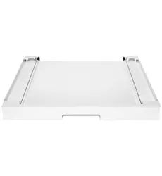
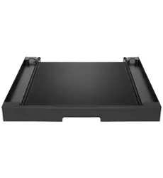
Ice Storage Bin
Hoshizaki IM-500SAB Stacking Kit Instructions
HS-5530
For Use with Hoshizaki Model IM-500SAB
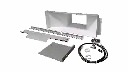
Check to ensure that all parts are included:
Index
No. Description Part Number Qty
Index
No. Description
Part
Number Qty
1 Ice Chute 1A5929-01 1 6 Water Guide 4A6891-01 1
2 Wire Harness 3B0590-01 1 7 Wire Saddle 4A2338-01 2
3 Top Panel Hook 3B0586-01 1 8 Wiring Label 2A9601-01 1
4 Thumbscrew 415949G10 2 9 Hex Bolt w/Washer (8×16) 7B0230816 2
5 Gasket
(125×1080 mm (5"×42 1/2"))
4A0808L02 1 10 Hex Nut (M8) 7N12-0800 2
11 Bracket Bin Control 4A7422-01 1
WARNING
• Only qualied service technicians should install this kit to reduce the risk of death, electric shock, serious injury, or re.
• Icemaker is heavy. Use care when lifting or positioning. Work in pairs when needed to prevent injury or damage.
• No installation or service should be undertaken until the technician has thoroughly read these instructions. Failure to follow
these instructions will adversely affect safety, performance, component life, and warranty coverage.
• Before Servicing: Move the control switch to the "OFF" position and turn off the power supply. Place the disconnect in
the "OFF" position. Lockout/Tagout to prevent the power supply from being turned back on inadvertently. Control switch in
"OFF" position does not de-energize all loads.
• CHOKING HAZARD: Ensure all components, fasteners, and thumbscrews are securely in place after the icemaker is
serviced. Make sure that none have fallen into the dispenser unit/ice storage bin.
• Make sure all food zones in the icemaker and dispenser unit/ice storage bin are clean after service.
• Protect the oor when moving the icemaker to prevent damage to the oor.
• Wear proper PPE (personal protection equipment) when executing these procedures.
• To reduce the risk of electric shock, do not touch the control switch with damp hands.
• The manufacturer cannot be held responsible for injury or damage resulting from improper, incorrect, and unreasonable
use or installation.
NOTICE!
• Do not use the frame to lift the icemaker. Lift the icemaker at the base or use a duct jack to lift the upper icemaker on top of
the lower icemaker.
• Up to three icemakers total (including the bottom icemaker) can be stacked.
Double Stacked: IM-500SAB × 2, Stacking Kit HS-5530 × 1
Triple Stacked: IM-500SAB × 3, Stacking Kit HS-5530 × 2
• The bin control switch on the lowest icemaker controls all icemakers. The bin control switch and switch mount must be
removed from the upper icemakers. Misconnection or no connection may cause damage to the icemakers, resulting in
icemaker failure or damage.
• Allow 6" (15 cm) clearance at rear, left side, and top (upper icemaker), and 12" (30 cm) clearance at right side for proper
air circulation and ease of maintenance and/or service should they be required.
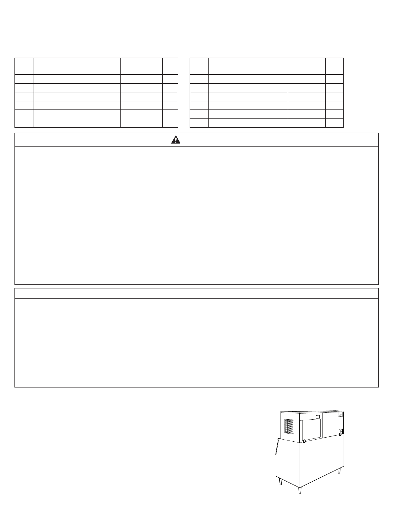
New Lower Icemaker Installation Instructions
1) Follow the Instruction Manual's installation instructions through "II.D.
Setup." When complete, continue to step 2.
Note: If installing an upper icemaker on an existing lower icemaker,
skip to step 2.
Lower Icemaker
2
2A9584-012
Fig. 2
Preparing Existing Lower Icemaker
2) Remove the front panel and move the control switch to the "OFF" position and turn off the power supply. Place the icemaker
disconnect (if applicable) in the "OFF" position. Lockout/Tagout to prevent the power supply from being turned back on
inadvertently. WARNING! Control switch in "OFF" position does not de-energize all loads.
3) Empty the ice storage bin of all ice.
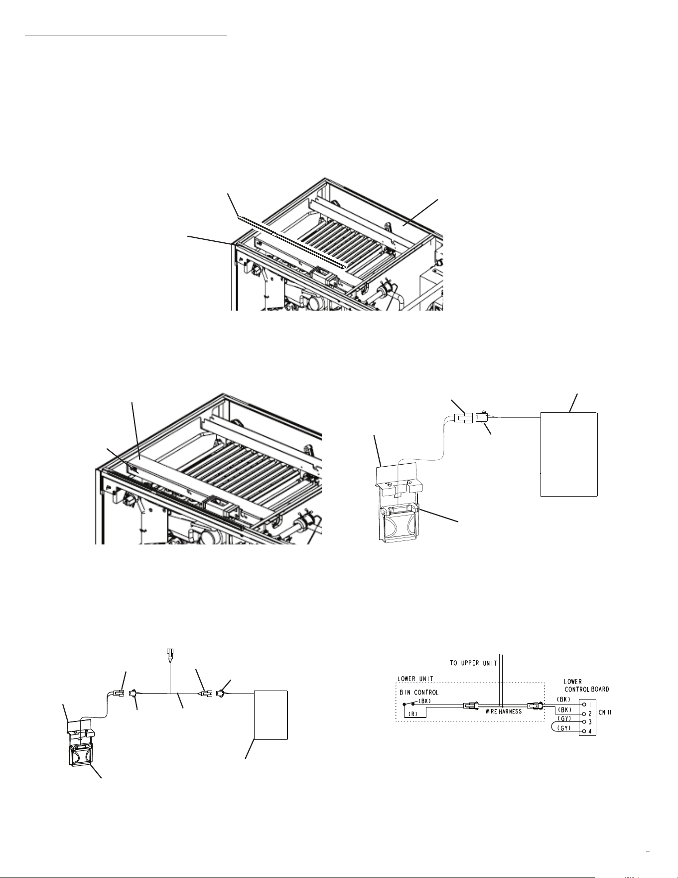
4) Remove the top, left, and right panels. See "II.C. How to Remove Panels" in the instruction manual. Also remove the lower
rear panel. See Fig. 1.
5) Remove the top frame front gasket from the lower icemaker. See Fig. 1. Next, place the top panel hook provided in this kit, on
top of the frame, then place the gasket provided in this kit, on top of the top panel hook.
Fig. 1
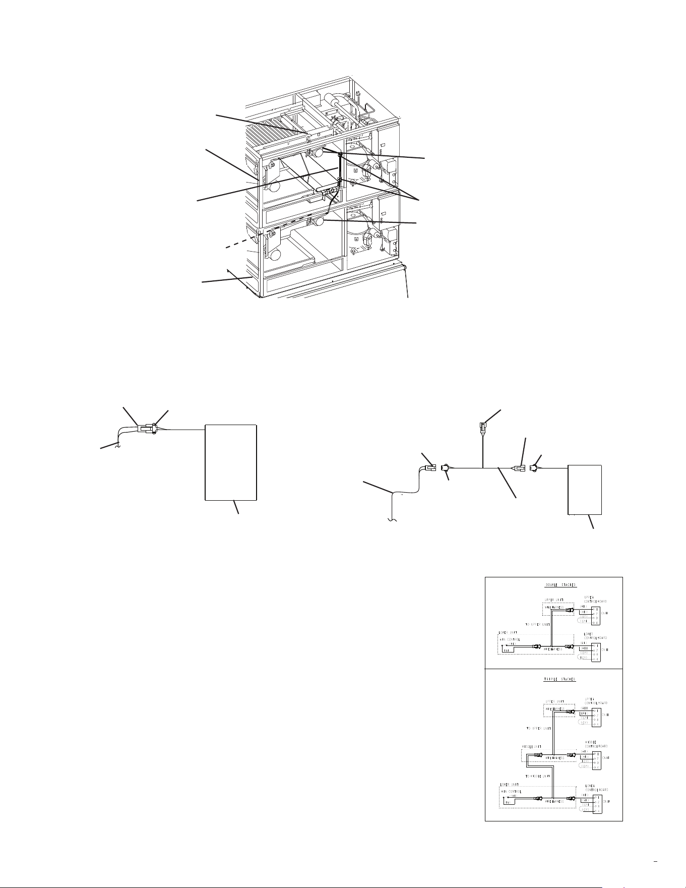
6) Remove connector guide A, then disconnect the bin control connector located in the wire channel. See Fig. 2.
Connector Guide A
Wire Channel
7) Connect the wire harness provided in this kit, to bin control connector B and control board connector A. See Fig. 3.
Fig. 3
Top Panel Hook
Top Frame Front Gasket
Lower Rear Panel
Connector B
Control Board
Connector A
Bin Control Assembly
Connector B
To Upper Icemaker
Control Board
Connector B
Wire Harness
Bin Control
Assembly
Connector A
Connector A
Bin Control
Bin Control
3
2A9584-012
Upper Icemaker Installation Instructions
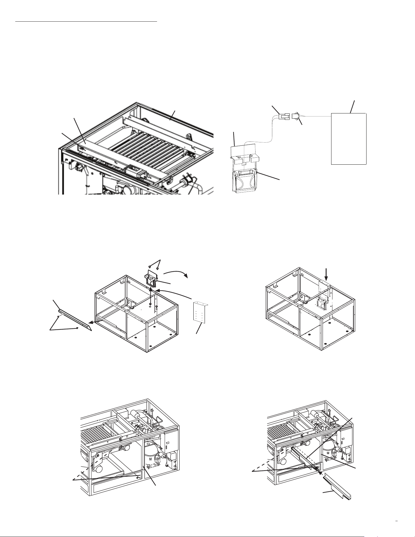
8) Remove the top, left, and right panels. See "II.C. How to Remove Panels" in the instruction manual. Also, if not already
removed, remove the lower rear panel. See Fig. 4.
9) Remove the protective plastic lm from the panels. If the icemaker is exposed to the sun or to heat, remove the lm after the
icemaker cools.
10) Remove the package containing the accessories.
11) Remove the shipping tape holding the bin control switch.
12) Remove connector guide A, then disconnect the bin control connectors located in the wire channel. See Fig. 4.
Fig. 6
13) Remove and discard the upper bin control assembly (bin control switch and bin control mounting bracket) and thumbscrews.
Remove the cube guide and thumbscrews. Discard the upper cube guide. Retain one of the thumbscrews for use later in
these instructions. See Fig. 5a.
14) Secure the bin control bracket to previous assembly holes. Place the bin control assembly to the bracket at desired height,
use thumbscrews to secure in place. See Fig. 5b.
15) Remove the 2 plastic separator protector screws, then pull the plastic separator protector out slightly. Slide the water guide
provided in this kit, between the plastic separator protector and sheet metal panel. See Figs. 6 and 7. Replace the 2 plastic
separator protector screws.
Fig. 4
Fig. 5a
Fig. 7
Connector B
Control Board
Bin Control
Assembly
Connector A
Bin Control
Lower
Rear Panel
Connector Guide A
Wire Channel
Bin Control Assembly
Thumbscrew
Upper Cube
Guide
Thumbscrew
Plastic Separator
Protector Screws
Sheet Metal
Panel
Plastic Separator
Protector Screws
Water Guide
Sheet Metal
Panel
Water Guide
Bin Control
Bracket
Fig. 5b
4
2A9584-012
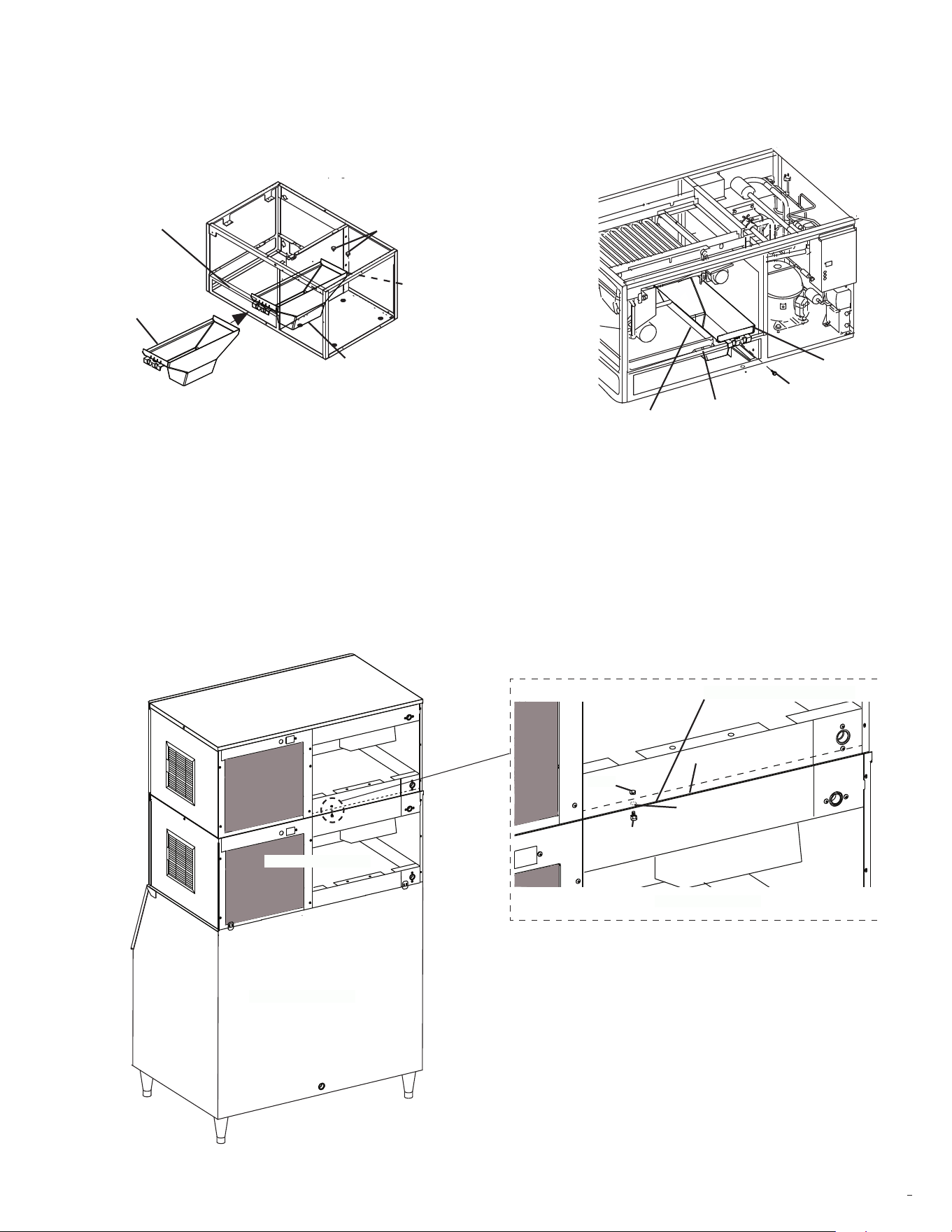
16) Place the new ice chute provided in this kit in position as shown in Fig. 8. Secure the rear of the ice chute to the upper
icemaker rear rail frame (bin control mounting bracket holes) with the new thumbscrews provided in this kit. Secure front of
the ice chute to the upper icemaker front rail frame (cube guide mounting hole) with the cube guide thumbscrew removed in
step 13. Conrm that the front of the ice chute clips over the front rail frame of the upper icemaker and that the drain pan is
not sitting on top of the ice chute. NOTICE! Conrm the drain pan is not sitting on top of the new ice chute.
17) Stack the upper icemaker on top of the lower icemaker. Use of a duct jack may be required. See Fig. 9. WARNING!
Icemaker is heavy. Use care when lifting or positioning. Work in pairs when needed and use a duct jack if available
to prevent injury or damage.
18) Once in place, make the front, rear, and side panels ush to the lower icemaker. See Fig. 9.
19) At the rear of the icemakers, locate the upper and lower icemakers rear mounting holes. See Fig. 9. To prevent plastic
shavings from entering the ice storage bin area during drilling, place a large pan or cloth under the icemakers rear mounting
holes. Using the icemakers upper or lower mounting hole as a guide, drill a 3/8" (10 mm) hole down or up through the top
plastic spacer between the upper and lower icemaker. See Fig. 10.
20) Secure the upper icemaker to the lower icemaker using one of the hex bolts w/washer and nuts provided in this kit.
See Fig. 10.
Fig. 8
Fig. 9
Fig. 10
Ice Chute
Front Rail Frame
Upper Icemaker
Thumbscrews
Rear Rail Frame
Front Rail Frame
Ice Chute
Drain Pan
Upper Icemaker
Ice Chute
Thumbscrew
Upper Icemaker
Upper Icemaker
Lower Icemaker
Ice Storage Bin
Lower Icemaker
Hex Bolt
w/Washer
Drill 3/8" (10 mm) Hole
Nut
Plastic Spacer
Rear Mounting Holes
5
2A9584-012
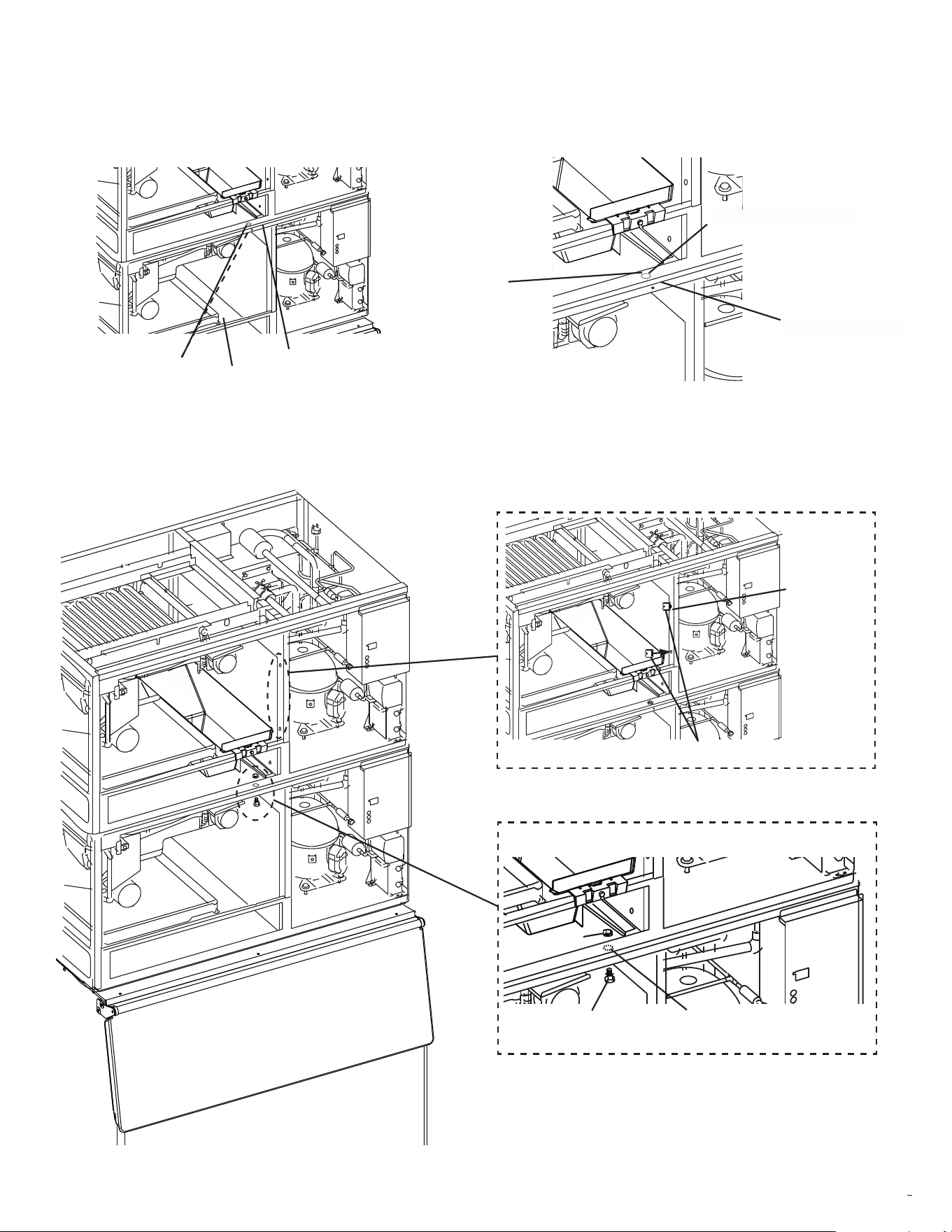
21) At the front of the icemakers, locate the lower and upper icemakers front mounting holes. See Fig. 11. To prevent plastic
shavings from entering the ice storage bin area during drilling, place a large pan or cloth under the icemakers front mounting
holes. Using the lower icemakers mounting hole as a guide, drill a 3/8" (10 mm) hole up through the top plastic spacer
between the upper and lower icemaker. See Fig. 12.
22) Secure the upper icemaker to the lower icemaker using the remaining hex bolt w/washer and nut provided in this kit.
See Fig. 13.
23) Place the wire saddles provided in this kit, into the upper icemaker evaporator frame. See Fig. 13.
Fig. 11
Fig. 12
Fig. 13
Nut
Upper Icemaker
Upper Icemaker
Drill 3/8" (10 mm) Hole
Lower
Icemaker
Upper and Lower
Icemakers Front
Mounting Holes
Top Plastic Spacer
Large Pan or Cloth
Top Plastic Spacer
Front
Mounting
Holes
Upper Icemaker
Upper
Icemaker
Evaporator
Frame
Lower
Icemaker
Wire Saddles
Upper Icemaker
Ice Storage Bin
Lower
Icemaker
Lower Icemaker
Front Mounting Holes
Hex Bolt
w/Washer
Lower
Icemaker
6
2A9584-012
24) Route the wire harness from the lower wire channel through the lower wire channel access hole with the lower icemaker
actuator motor wires. Then, up into the upper icemaker between the frame and the new ice chute through the wire saddles
and into the upper wire channel through the upper wire channel access hole with the upper icemaker actuator motor wires.
See Fig. 14.
25) Connect wire harness connector B to the control board connector A. See Fig. 15. Replace connector guide A on all
icemakers.
26) If stacking 3 icemakers, repeat steps 5 - 25.
27) Follow the instruction manual instructions to complete the lower
(if applicable) and upper icemaker electrical, water, and drain
installation requirements. See sections "II.E." through "II.H."
28) When performing step 12 in "II.H. Startup." Conrm that all icemakers
shutdown within 15 sec. after pressing the bin control paddle.
29) Place the wiring label provided in this kit on the control box cover.
See Fig. 16.
30) Replace and secure all parts and panels in their correct positions.
31) Make sure all food zones, surface areas, and icemakers are wiped
down, cleaned, and sanitized after installation.
Fig. 14
Fig. 15
Fig. 16
Upper Icemaker
Upper Wire Channel
Wire Harness
Lower Icemaker
Lower Wire Channel
Upper Icemaker
Actuator Motor
Wire Saddles
Lower Icemaker
Actuator Motor
Connector B
Connector A
Control Board
Wire Harness
From Lower
Icemaker
Connector B
Connector B
Connector A
Connector A
Control Board
Wire Harness
Wire Harness
From Lower
Icemaker
To Lower Icemaker
To Upper (Third) Icemaker (if applicable)
Middle Icemaker Connection Triple Stack
Upper Icemaker Connection Double or Triple Stack
Double or Triple Stacked Wiring Label