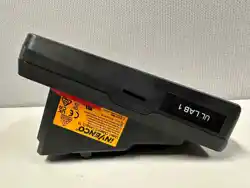

Page | 1
G6-500NFC (A2-05)
User Guide
DCV-00660 S2 R06
First Published: November 01 2022
Document Number: DCV-00660-S2-R06
Revision Date: May 27 2026
S2 Security Level Guide
No Restrictions apply: Customer-facing document.

Page | 2
Document History
Issue
Date of Issue
Description
Originator
R01
2022-11-01
Created document
SP
R02
2023-09-27
Updated content for OPT
SJ
R03
2024-02-02
Included references for External Display Modules
SD
R04
2024-11-12
FCC information Updated
Added Reference to M2-15
Added MSR Logo
SD
R05
2026-02-09
Added A2-05 Fan Kit information
SD
R06
2026-05-27
Updated for G6-500NFC Module
SD

Page | 3
Table of Contents
Contents
CHAPTER 1 - Introduction to G6-500NFC Module .................................................................................................... 5
1.1. Where can the G6-500NFC Module be Installed? ...................................................................... 5
CHAPTER 2 - Safety & Compliance Information ........................................................................................................ 6
2.1. Preliminary Precautions ............................................................................................................. 6
2.2. Safely Accessing a Fuel Pump ................................................................................................... 6
2.3. Follow the Regulations ............................................................................................................... 7
2.4. Replacement Parts .................................................................................................................... 7
2.5. Safety Symbols and Warning Words .......................................................................................... 7
2.6. Prevent Explosions and Fires ..................................................................................................... 7
2.7. Working Alone ............................................................................................................................ 8
2.8. Safety First: Working with Electricity ........................................................................................... 9
2.9. Hazardous Materials .................................................................................................................. 9
2.10. In an Emergency ........................................................................................................................ 9
2.11. Computer Programs and Documentation ................................................................................. 10
CHAPTER 3 - Approvals ............................................................................................................................................ 11
3.1. European Directives ................................................................................................................. 12
3.2. UK Conformity Assessed.......................................................................................................... 12
3.3. Australia and New Zealand Compliance ................................................................................... 12
3.4. Industry Canada ....................................................................................................................... 12
3.5. FCC ............................................................................................................................................................ 13
CHAPTER 4 - Product Features................................................................................................................................. 14
4.1. Location of Features ................................................................................................................ 14
4.2. External Display Modules ........................................................................................................ 18
4.3. Fan Module .............................................................................................................................. 19
CHAPTER 5 – Display Module Interfaces ................................................................................................................ 20
CHAPTER 6 - Location of Mounting Points ............................................................................................................. 21
CHAPTER 7 - Installation ............................................................................................................................................ 22
7.1. Installing a Brand New G6-500NFC Module .............................................................................. 22
CHAPTER 8 - Tools Required to Mount the G6-500NFC......................................................................................... 23
CHAPTER 9 - Installing into a New Pump or Cabinet ............................................................................................. 24
CHAPTER 10 - Power Supply Considerations ......................................................................................................... 25
CHAPTER 11 – G6-500NFC Wiring ........................................................................................................................... 26
11.1. Protective Earth ....................................................................................................................... 27

Page | 4
11.2. Ethernet LAN ........................................................................................................................... 28
11.3. DC Power IN ............................................................................................................................ 28
CHAPTER 12 - Main Power Supply Wiring ............................................................................................................... 29
CHAPTER 13 - Wiring Completion ............................................................................................................................ 30
CHAPTER 14 - First Power - Up ................................................................................................................................ 31
14.1. Normal Start-Up ....................................................................................................................... 31
14.2. Edit Configuration ..................................................................................................................... 33
CHAPTER 15 - Tamper-Detection .............................................................................................................................. 34
CHAPTER 16 - Basic Maintenance ............................................................................................................................ 35
16.1. Cleaning G6-500NFC (A2-05) Module ...................................................................................... 35
16.2. A2-05 Fan Kit Maintenance ...................................................................................................... 35
CHAPTER 17 - Security Checks ................................................................................................................................ 36
17.1. Built in Security ........................................................................................................................ 36
17.2. Extra Security Checks .............................................................................................................. 36
17.3. Escalation ................................................................................................................................ 36
CHAPTER 18 - Inspection ........................................................................................................................................... 37
18.1. Card-Reader Slot ..................................................................................................................... 37
18.2. Contactless Reader ................................................................................................................. 38
18.3. Magstripe ................................................................................................................................. 38
CHAPTER 19 - Removal & Re installation ................................................................................................................ 39
19.1. How to Uninstall a G6-500NFC Module and A2-05 Fan Kit ...................................................... 39
19.2. How to Reinstall a G6-500NFC module and A2-05 Fan Kit ...................................................... 39
CHAPTER 20 - Drawings ............................................................................................................................................ 40
20.1. Dimensions .............................................................................................................................. 40
CHAPTER 21 - Mounting - New Installation ............................................................................................................. 45
CHAPTER 22 - Typical Wiring ................................................................................................................................... 47

G6-500NFC User Guide, DCV-00660 S2 R06
Page | 5
CHAPTER 1 - Introduction to G6-500NFC Module
The Invenco® G6-500NFC Module (Outdoor payment terminal) is an industrial multimedia device tailor-made for the
outdoors. It is a feature rich cost-effective product that includes contact and contactless card readers with a touch
screen for display prompts and PIN-entry. A cooling fan module, designed to mount at the rear of the
G6-500NFC unit, is also available for installations requiring enhanced thermal management.
The form factor of the A2-05 makes it suitable for use in the petroleum market, EV Charging stations, quick service
restaurants, drive through lanes, or as a replacement for the UPC and SCC (and APC as well) for the FlexPay 6 M1-
15. The FlexPay 6 M2-15 pairs the G6-500NFC module with the M-UD15 touch screen as a next-generation
replacement of the M1-15. The payment terminal features the ability to use an external display allowing retailers to
engage with their customers through targeted advertising or in-store sales.
The Payment terminal is designed to be durable and tough, yet simple and secure to use. To ensure optimal
performance of the A2-05, including when equipped with the rear cooling fan module, proper installation and regular
maintenance are essential.
This guide will walk you through installation and correct care for your new G6-500NFC Module (A2-05).
Note: If you are installing an OPT using an approved retrofit kit, the instructions with the kit supersede the
instructions in this guide.
1.1. Where can the G6-500NFC Module be Installed?
The G6-500NFC (A2-05) is a multi-purpose Outdoor Payment Terminal (OPT) designed for unattended use.
It operates in a range of outdoor environments in temperatures from -30°C (-22°F) through to +70°C (158°F).
The focus of this guide is for installation into fueling dispensers. However, this guide should be seen as
encompassing for all energy dispensers.
Specific steps and precautions for fueling dispenser installation are highlighted.
Please, always use safety precautions when installing our products.

G6-500NFC User Guide, DCV-00660 S2 R06
Page | 6
CHAPTER 2 - Safety & Compliance Information
STOP There are hazards and safety precautions associated with installing, inspecting, maintaining or servicing this
product.
Important: Before you start, READ! You need to understand the safety information in this manual. Hazards and
safety precautions for tasks are always listed.
Fire, explosion or electrical shock could occur and cause death or serious injury if these safe service
procedures are not followed.
2.1. Preliminary Precautions
Fuel stations can be a dangerous place to work - there are flammable fuels, vapors and high voltages.
You should only install, inspect, maintain or service this equipment when you are fully trained and authorized to do so.
2.2. Safely Accessing a Fuel Pump
2.2.1 Evacuation and Barricading
If you need to access a pump/dispenser head, then you must:
• Evacuate all unauthorized persons and vehicles.
• Use safety tape or cones as a barricade to the affected unit(s).
2.2.2 Total Electrical Shut-Off
Before accessing the electrical components or the electronics of a pump/dispenser, you must carry out a total
electrical shut-off of that unit.
To shut off electricity find the switch or circuit breaker and turn it to the “off” position.
If you can’t turn off the power, STOP. Do not continue until the electricity has been safely turned off by you or
someone else.
2.2.3 Read the Manual
Read, understand and follow this manual and any other labels or related materials supplied with this equipment. If you
do not understand a procedure, call an Invenco-authorized service contractor.

G6-500NFC User Guide, DCV-00660 S2 R06
Page | 7
WARNING:
For your own safety and that of others, you must understand the procedures before beginning
work.
2.3. Follow the Regulations
Regulations exist to keep everyone safe.
You are expected to follow:
• OSH regulations.
• National regulations and codes.
• State regulations and codes.
• Local regulations and codes.
Note:
If you do not install, inspect, maintain or service this equipment in accordance with these codes, regulations
and standards, it may affect the safe use and operation of the equipment, or lead to legal citations with
penalties.
2.4. Replacement Parts
Use only genuine Invenco replacement parts and retrofit kits on your installation.
Using parts other than genuine Invenco replacement parts could create a safety hazard and violate both, legal and
certification requirements. This is not an approved practice.
2.5. Safety Symbols and Warning Words
Throughout this guide you will see warnings and notes in boxes like below. These are used to let you know when you
need to take extra caution in order to avoid hazards and/or potential injury to yourself or another person.
Always follow these instructions!
WARNING:
This alerts you to a hazard or unsafe practice that could result in death or serious injury.
Note: This designates a hazard or unsafe practice which may result in minor injury or a legal issue.
2.6. Prevent Explosions and Fires
Fuels and their vapors will become explosive if ignited.
All fuels cause vapors when they are exposed to air and transferred between containers, spilled or leaking fuels
cause even more vapors.

G6-500NFC User Guide, DCV-00660 S2 R06
Page | 8
When a customer’s tank is filled, vapors leak into the air around the tank and island, and these vapors can potentially
catch fire or explode if they are exposed to a spark or flame.
This is why every single person on a fuel station forecourt must be aware of the danger of sparks and open flames
and take precautions to avoid explosions and fires.
2.6.1 No Open Flames
Open flames from matches, lighters, welding torches or other sources can ignite the fuel and vapors present on
forecourts.
There should never be an open flame on a fuel station forecourt for any reason.
2.6.2 No Sparks - No Smoking
Sparks can also start a fire or cause an explosion on a forecourt. Be safety conscious!
Do not:
1. Smoke.
2. Light a match.
3. Use a lighter.
4. Use a mobile phone outside of your car.
5. Start or use power tools.
6. Create a flame of any kind.
Also beware of:
1. Static electricity.
• Always touch the metal of your vehicle after you get out of it to discharge any electrostatic charge before
you approach the dispenser island.
2.7. Working Alone
2.7.1 Best Practice
Always work with at least two people if possible; one to actively work and one as an assistant/backup.
Ideally if you are working around high voltages, the backup/assistant should be trained in providing Cardiopulmonary
Resuscitation (CPR).
2.7.2 Safety First!
Whether working alone or with someone else:
1. Advise station personnel where you will be working.
2. Warn station personnel not to turn the power back on while you are working on the equipment.
3. Use the OSH tag out and lock out procedures.
• If you are not familiar with this requirement, refer to the information in the service manual and the OSH
documentation.

G6-500NFC User Guide, DCV-00660 S2 R06
Page | 9
2.7.3 Installer Certification
Many countries’ authorities require people working in hazardous environments to hold additional qualifications that
prove they are suitably skilled to perform work on fuel station forecourts.
Please ensure that you have the relevant certifications and that they are current, before attending to any site to
perform installation work.
2.8. Safety First: Working with Electricity
Always:
1. Use safe and established practices.
2. Follow OSH Lock-Out and Tag-Out requirements before carrying out any service or installation work.
3. Check all devices before use.
• Is the wiring in good condition?
• Is the grounding connection firmly attached?
• Are all sealing devices and compounds intact and in place?
Never:
1. Use devices if they have any damage.
2. Skip over safety procedures for any reason.
• Faulty wiring or unsafe procedures can cause a fire, explosion or electrical shock.
Station employees and service contractors must understand and comply with these guidelines completely to ensure
safety while the equipment is down.
2.9. Hazardous Materials
Some materials present inside electronic enclosures may present a health hazard if not handled correctly.
• Always wear gloves if practical to do so.
• Keep your hands away from your eyes and mouth during installation.
• Wash your hands as soon as possible.
2.10. In an Emergency
Contact your country’s emergency number immediately.
Emergency personnel will need the following information:
• Location of accident (e.g., address, front/back of building).
• Nature of accident (e.g., possible heart attack, run over by car, burns).
• Approximate age of victim (e.g., baby, teenager, middle-age, elderly).
• Whether or not victim has received first aid (e.g., stopped bleeding by pressure).
• Whether or not victim has vomited (e.g., if swallowed or inhaled something).

G6-500NFC User Guide, DCV-00660 S2 R06
Page | 10
WARNING:
Oxygen may be needed at scene if gasoline has been ingested or inhaled. Seek
medical advice immediately.
2.11. Computer Programs and Documentation
All Invenco Group Ltd. software (including software on discs and within memory chips) and documentation are
copyrighted by, and shall remain the property of, Invenco Group Ltd.
The duplication, disclosure, modification, or unauthorized use of software programs or documentation is strictly
prohibited unless otherwise licensed by Invenco Group Ltd.
G6-500NFC User Guide, DCV-00660 S2 R06
Page | 11
CHAPTER 3 - Approvals
Invenco develops and maintains its hardware and software products using industry-standard quality processes and
is audited by the MasterCard TQM (Terminal Quality Management) scheme.
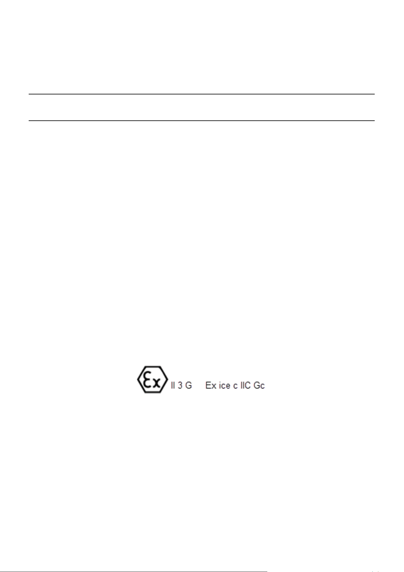
The G6-500NFC Module has the following safety approvals:
Hazardous Location Safety Certification
CSA C22.2 No. 213-17 (Hazardous location safety – Class I Division 2).
UL 121201 and CAN/CSA C22.2 No. 213-17, Non-incendive Electrical Equipment (Class I Division 2, Groups A, B,
C and D).
USA: AZOW2.E480135.
Canada:
AZOW8.E480135.
Ordinary Location Safety Certification
IEC/EN/AS/NZS/UL 62368-1 & CSA C22.2 No. 62368-1-14 (Safety - Audio/video, information, and communication
technology equipment).
USA: AZOT.E469526.
Canada: AZOT7.E469526.
ATEX Certification (Potentially Explosive Atmospheres)
EN IEC 60079-0
EN IEC 60079-7
EN 60079-11
Retrofit Safety Certification
UL 1238, UL 87 & CSA C22.2 No. 213-17, CSA B346-M1980, CSA C22.2 No. 22 (Retrofit
assemblies). USA: ERKQ.MH61528.
Canada: ERKQ7.MH61528.
EMC
EN 300 300 & ETSI 301 489-3 (in conjunction with ETSI 301 489-1) for Radio.
FCC certification 47 CFR Part 15C.
IC certification (RSS-Gen & RSS-210).
SIRIM (Malaysia) certified: IDM20000040.

G6-500NFC User Guide, DCV-00660 S2 R06
Page | 12
Environmental Compliance:
RoHS compliance with Directive 2011/65/EU & Commission delegated directive (EU) 2015/863 and The Restriction
of the Use of Certain Hazardous Substances in Electrical and Electronic Equipment Regulations 2012.
EMV Certification
The terminal is certified by EMV Co for EMV L1 Contact, L2 Contact, L1 Contactless.
It also has certifications for performing EMV transactions as defined by Visa, Mastercard, Discover, Amex, Interac,
JCB, CUP, ECB and Pure schemes.
PCI -PTS -POI (Payment Card Industry) - PCI 6.X.
Note: The G6-500NFC (A2-05) Certification includes the Fan Kit, however the A2-05 fan kit also has its own module
certification marking and declarations as applicable with respect to UL recognised component, CE and UKCA marks
in case the A2-05 Fan Kit is shipped separately as a module.
3.1. European Directives
The G6-500NFC (A2-05) complies with the necessary European Directives for the CE mark.
3.2. UK Conformity Assessed
The G6-500NFC (A2-05) complies with the necessary UK Conformity Assessments for the UKCA mark.
3.3. Australia and New Zealand Compliance
The G6-500NFC (A2-05) complies with the necessary Australia and New Zealand compliance requirements for the
RCM mark.
3.4. Industry Canada
IC ID: 12614A-G6500NFC
This device complies with Industry Canada's license-exempt RSSs. Operation is subject to the following two
conditions:
1. This device may not cause interference; and

G6-500NFC User Guide, DCV-00660 S2 R06
Page | 13
2. This device must accept any interference, including interference that may cause undesired operation of the
device.
3.5. FCC
Supplier's Declaration of Conformity
47 CFR § 2.1077 Compliance Information
FCC ID: 2AC7B-G6500NFC
Unique Identifier:
Invenco, G6-500NFC (A2-05)
Responsible Party:
Invenco i2 Incorporated
Address: 245 Hembree Park Drive Suite 90 Roswell, GA 30076
Email: support@invencoi2.com
This device complies with part 15 of the FCC Rules. Operation is subject to the following two conditions:
1. This device may not cause harmful interference, and
2. This device must accept any interference received, including interference that may cause undesired opera-
tion.
Note: The grantee is not responsible for any changes or modifications not expressly approved by the party respon-
sible for compliance. Such modifications could void the user’s authority to operate the equipment.
Note: This equipment has been tested and found to comply with the limits for a Class B digital device, pursuant to
part 15 of the FCC Rules. These limits are designed to provide reasonable protection against harmful inter-
ference in a residential installation. This equipment generates, uses and can radiate radio frequency energy
and, if not installed and used in accordance with the instructions, may cause harmful interference to radio
communications. However, there is no guarantee that interference will not occur in a particular installation. If
this equipment does cause harmful interference to radio or television reception, which can be determined by
turning the equipment off and on, the user is encouraged to try to correct the interference by one or more of
the following measures:
• Reorient or relocate the receiving antenna.
• Increase the separation between the equipment and receiver.
• Connect the equipment into an outlet on a circuit different from that to which the receiver is connected.
• Consult the dealer or an experienced radio/TV technician for help.
G6-500NFC User Guide, DCV-00660 S2 R06
Page | 14
CHAPTER 4 - Product Features
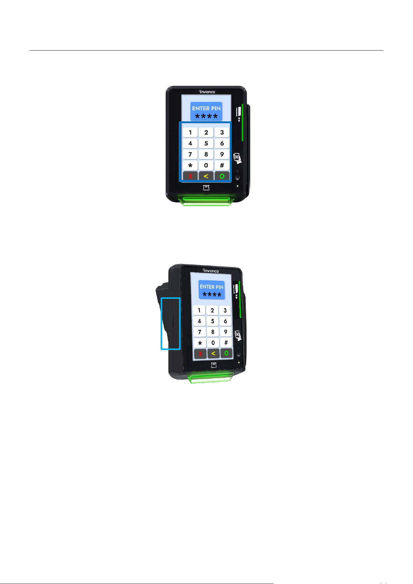
4.1. Location of Features
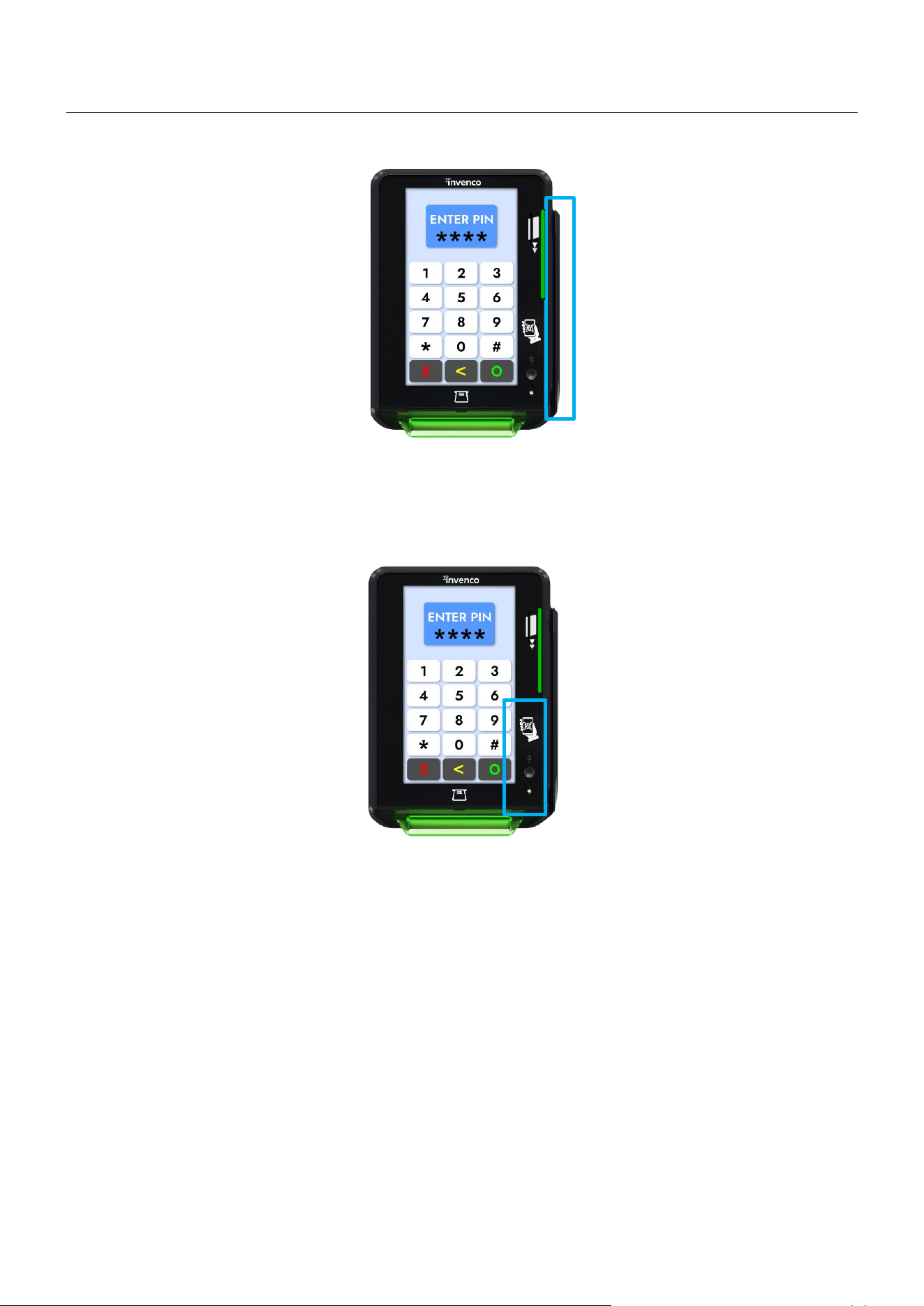
G6-500NFC (A2-05) Contactless Card Reader.
G6-500NFC (A2-05) ICC Reader
G6-500NFC User Guide, DCV-00660 S2 R06
Page | 15
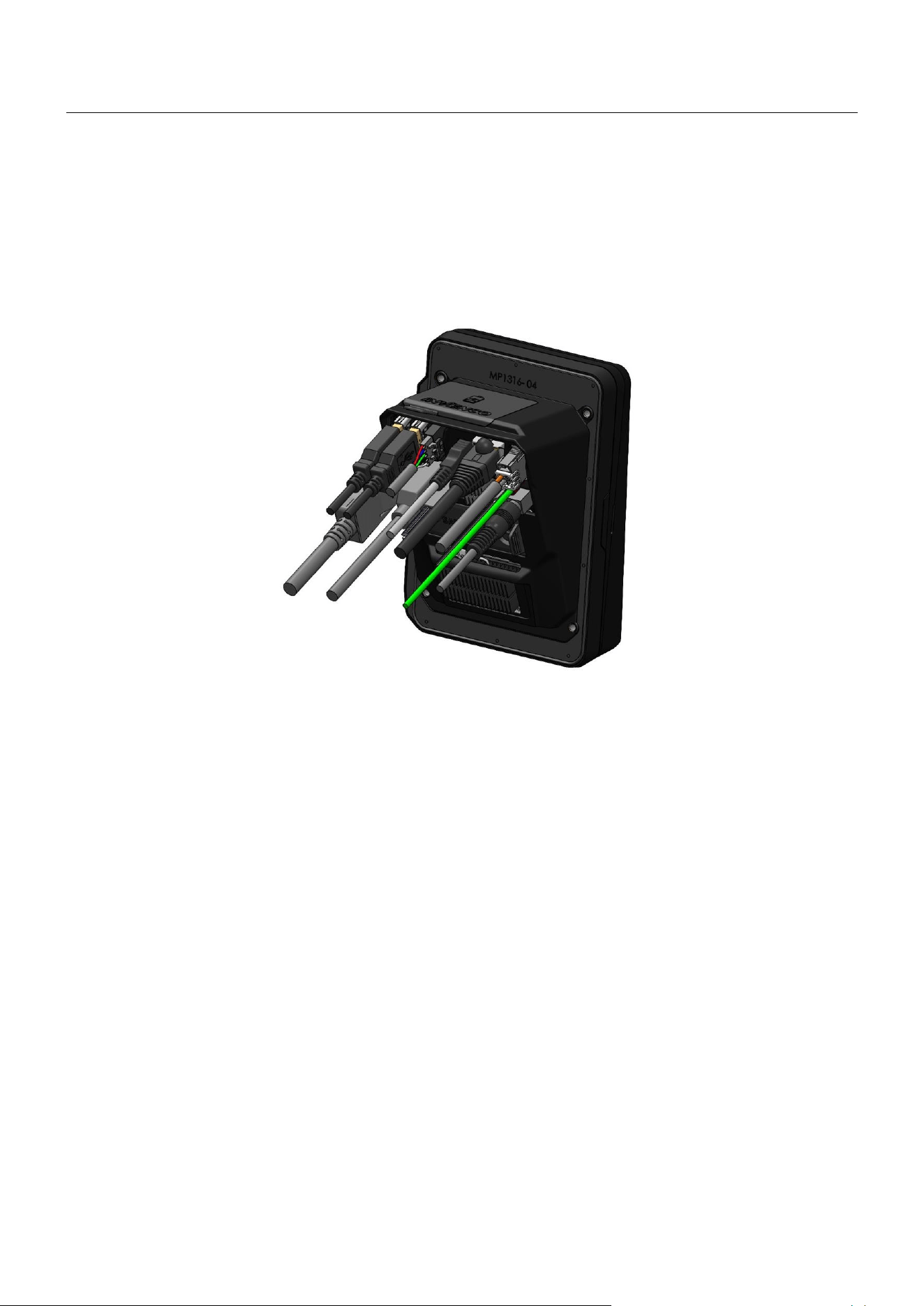
Pin on Glass
G6-500NFC (A2-05) Speaker.
G6-500NFC User Guide, DCV-00660 S2 R06
Page | 16
Magstripe Reader
Barcode Reader
G6-500NFC User Guide, DCV-00660 S2 R06
Page | 17
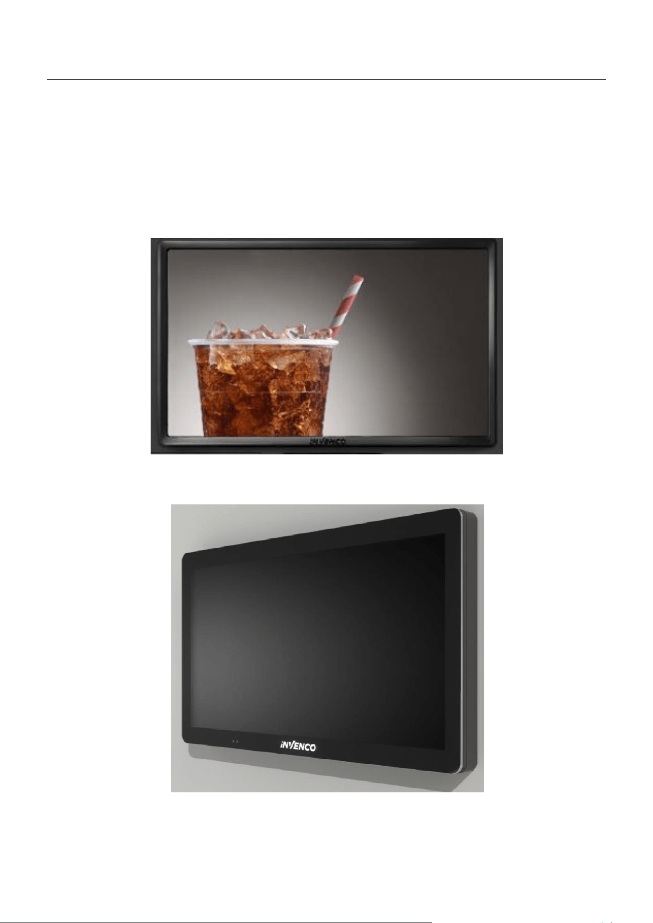
G6-500NFC (A2-05) Rear View (Mounting is EVA Compliant, mounting plate optional)
G6-500NFC User Guide, DCV-00660 S2 R06
Page | 18
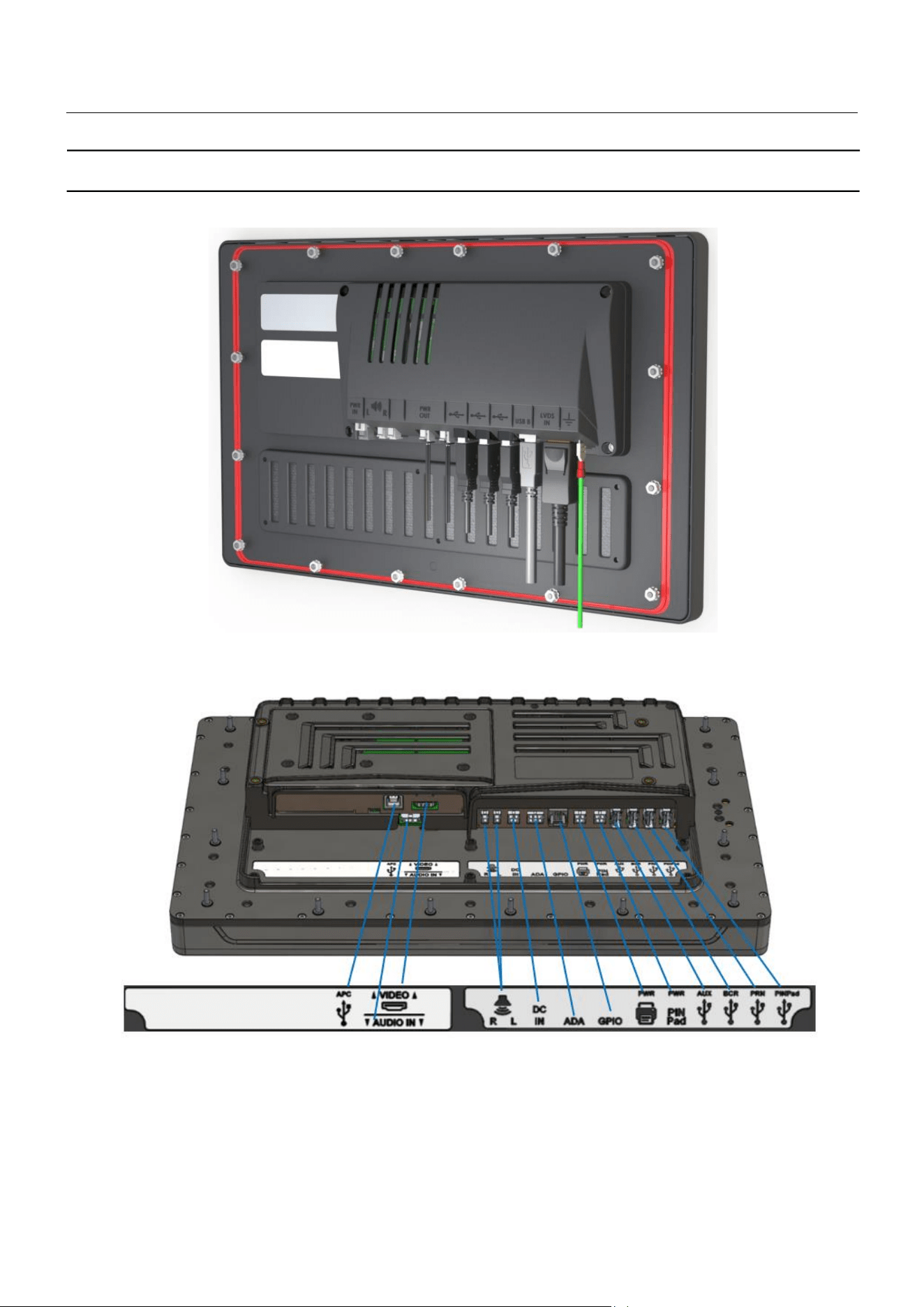
4.2. External Display Modules
The G6-500NFC (A2-05) also features the ability to use an external display connecting to either an HDMI or
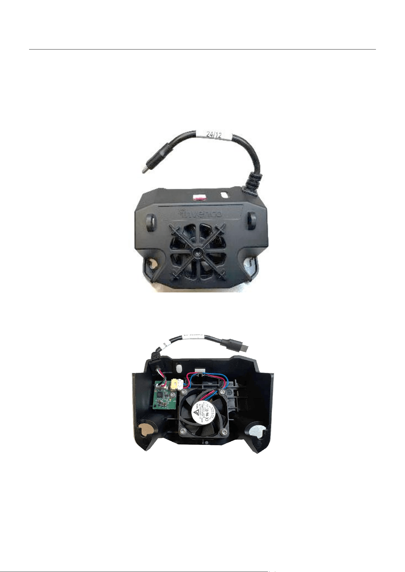
LVDS output, allowing retailers to engage with their customers through targeted advertising or in-store sales.
Our largest G7-100 SDC-15
(secure display controller 15 inch) and M-UD15 (UD15 - Universal display 15
inch) offers a stunning display that will catch your customer’s eye. The FlexPay 6 M2-15 pairs the
G6-
500NFC (A2-05)
with the FP6 M-UD15 touch screen as a next generation replacement of M1-15. Refer to
User Guide DCV-00717 for more details on M-UD15.
Figure 4-2 Invenco G7-100 SDC-15 (SDC 15 inch)
Figure 4-3 Invenco M-UD15 (UD15)
G6-500NFC User Guide, DCV-00660 S2 R06
Page | 19
4.3. Fan Module
The G6-500NFC (A2-05) must be fitted with a cooling fan module that connects to the USB-C port located on
the back of the unit.
Figure 4-4 A2-05 Fan Kit
Figure 4-5 A2-05 Fan Kit Rear View
G6-500NFC User Guide, DCV-00660 S2 R06
Page | 20
CHAPTER 5 – Display Module Interfaces
Figure 5-1 Universal Display 15” (UD15) interfaces
Figure 5-2 Secure Display Controller 15” (SDC 15”) interfaces
G6-500NFC User Guide, DCV-00660 S2 R06
Page | 21
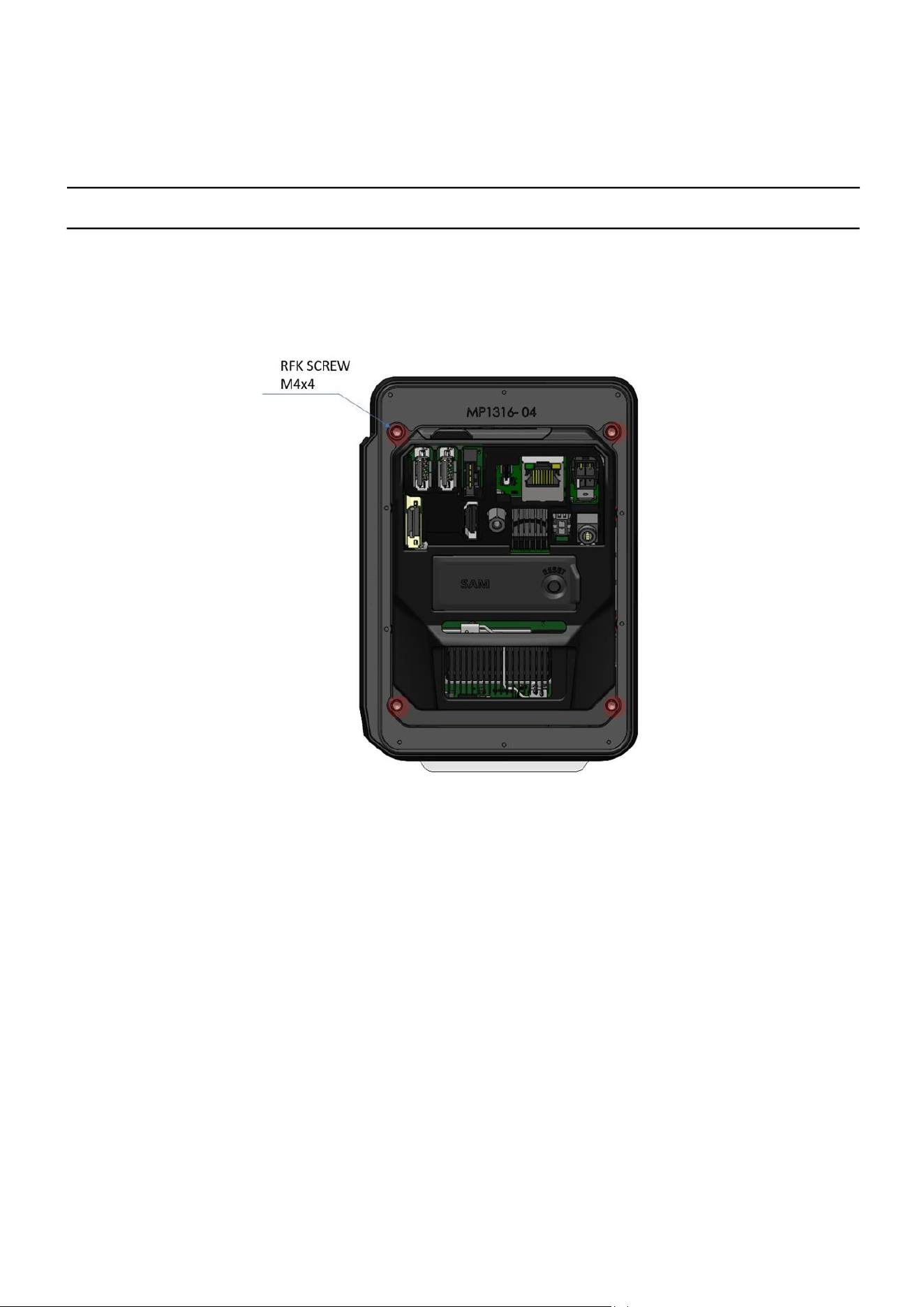
CHAPTER 6 - Location of Mounting Points
Red highlights show the standard mounting points for a new installation. Each mounting point has an M4 screw that
screws the G6-500NFC (A2-05) to the pump.
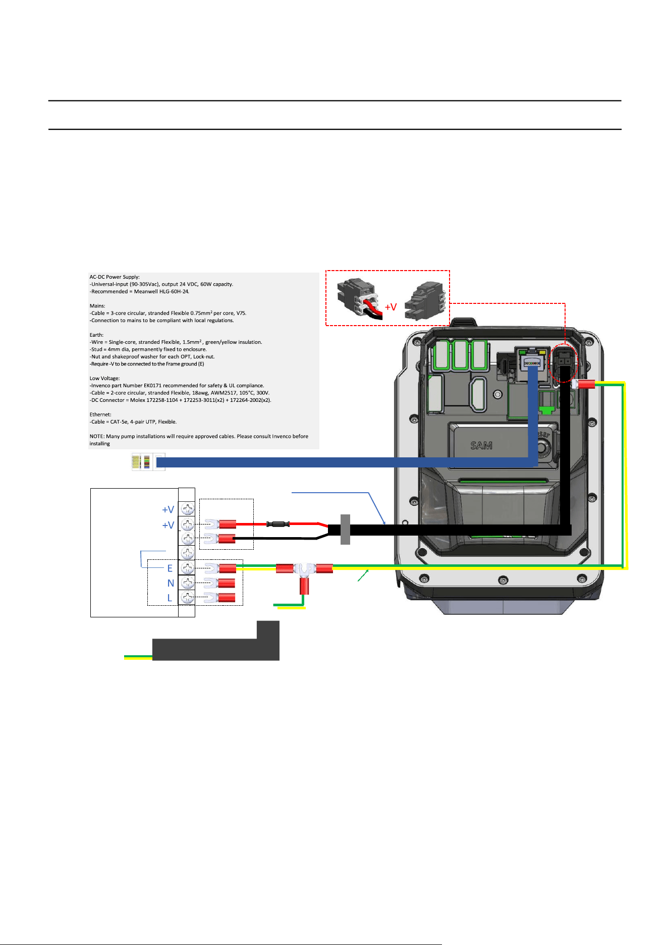
See the Drawings at the end of this guide for panel cut-out information.
Location of Mounting Points (in red)

G6-500NFC User Guide, DCV-00660 S2 R06
Page | 22
CHAPTER 7 - Installation
7.1. Installing a Brand New G6-500NFC Module
In most cases a new installation must be done by the pump manufacturer, not a third party. Each pump has safety
certifications that can be invalidated if anyone other than the manufacturer modifies it. Before a G6-500NFC module
can be installed, the pump enclosure must meet the following standards:
1. Fire. The enclosure must be designed to meet the requirements of ISO/EN 60950-1 for fire enclosures.
2. ATEX (Explosive Atmospheres). The G6-500NFC has openings that prevent it being gas-tight. Because of
this, it should be installed away from all hazards. Refer to local laws and regulations for hazardous zones to
work out the best mounting place for the G6-500NFC. The pump or cabinet that the G6-500NFC is mounted
in should also be designed to prevent a dangerous build-up of explosive gases.
3. Security. The pump or cabinet should offer physical security to protect the public from the hazards within, and
to reduce the ability of anyone to tamper with the OPT.
4. Power & Data.
a. The pump or cabinet must provide mains power. The requirements are:
i. A permanently wired connection or a socket to plug it into.
ii. A protective earth connection.
iii. The outlet may be switched if it is a socket and must be switched if it is permanently wired.
iv. We recommend one Power Supply Unit (PSU) per G6-500NFC.
b. The pump or cabinet must provide an Ethernet data connection. The requirements are:
i. Capable of at least 10Mbps (preferably 100Mbps).
ii. The connection must be either a socket into which a standard Ethernet patch cable can be connected, or
a cable that is terminated in a standard RJ45 plug suitable for direct connection into the OPT LAN
socket.
iii. Minimum cable standard should be Cat5e.
iv. The enclosure may provide an alternative data connection for terminals that have optional
communications modules installed. Please consult with Invenco for what options are available.
5. Accessibility. The enclosure must be designed and mounted at a height so disabled persons are able to
operate the device. Height must be compliant with PCI 6.X standards.
6. Materials. The enclosure and all its components must be constructed of durable materials suitable for the
intended location.
7. Door cut-out. The edge of the cut-outs should be smooth and free of burrs, and the surface of the door
around the cut-out should be clean, and planar within ± 1mm.
8. Water-Tightness. The G6-500NFC is rated for IPX6 on the customer facing side. The parts sitting inside the
pump/pedestal enclosure are designed to reduce the likelihood of water entering the electronics but the
enclosure must provide protection from water. The door should have a water seal against the enclosure, and
there should be good drainage and/or a system to reduce excessive condensation build-up and dripping.
9. Protection from Weather Extremes. While the G6-500NFC is intended for use outdoors, exposure to direct
sunlight and/or heavy rain can affect customers’ experience using the product. The pump or enclosure
should provide a canopy that prevents the OPT from being exposed to direct sunlight and heavy rain. If the
OPT cannot be protected from direct sunlight, a warning sign should be provided close to the OPT advising
that the screen may become too hot to touch.
10. Placement. The G6-500NFC must always be installed in an upright (vertical) position to a backward
maximum incline of 20 degrees.

G6-500NFC User Guide, DCV-00660 S2 R06
Page | 23
CHAPTER 8 - Tools Required to Mount the G6-500NFC
• 4 x M4 screws of the correct length to attach the OPT to your pump/cabinet.
Note: Screws are not provided with the product, for the two upper mounting locations, use 2 × M4 × 10 mm screws.
For the two lower mounting locations, use MS0162 – M4 × 12 mm screws, which are included in the A2-05 Fan Kit.
• A 2.5mm Hex driver or Allen Key to fit the M4 screws.
• Philips #1 or Flat 5mm screwdriver – for connections on the power supply.
• Philips #2 screwdriver for connecting the M4 screws to the OPT.
• Small adjustable spanner – for earth connections inside the cabinet.
• Cable ties.
• Side cutters – to trim the cable tie(s).
• You may require other tools if retrofitting into a non-standard enclosure.
WARNING: Do not use power tools if working on a fuel station forecourt. Any spark could
cause a fire or explosion.
G6-500NFC User Guide, DCV-00660 S2 R06
Page | 24
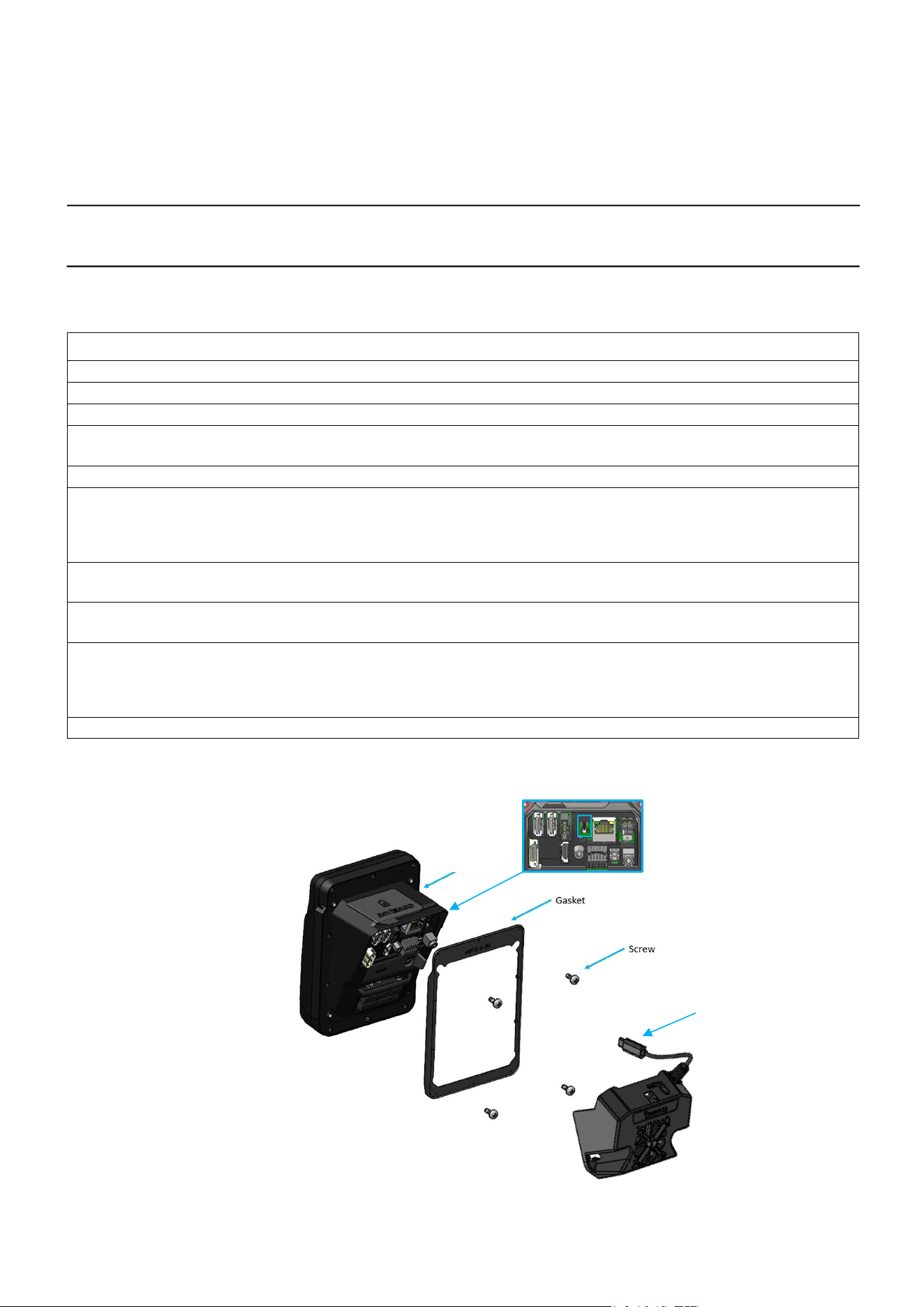
CHAPTER 9 - Installing into a New Pump or Cabinet
Step Instructions
1. Unpack the G6-500NFC module and the A2-05 Fan Kit as per the Invenco Shipping Guide.
2. Open the pump/cabinet door.
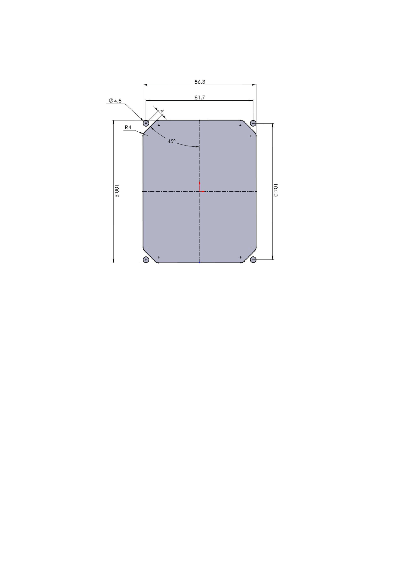
3. Attach the gasket to the back of the unit, following the separate instructions below.
4. Hold the G6-500NFC module outside the pump/cabinet and locate at least one of the top
mounting screws M4x10 mm. Loosely screw it in.
5. Start several of the remaining support screws around the edge of the G6-500NFC.
6. Verify that the G6-500NFC is properly aligned with any features on the pump or cabinet door,
then tighten the top two screws to a torque of 0.65 Nm to 0.70 Nm. For the bottom two screws,
partially insert until the head is approximately 3mm from the panel and its fully assembled
position.
7. Position the A2-05 fan kit, aligning the 2 slots below the two bottom partially installed screws, slide the kit
upwards as far as it can go ensuring it is correctly aligned with screw positions.
8. While pulling the assembly up, tighten the screws to a torque of 0.65 Nm to 0.70 Nm to securely
fasten the Fan Kit to the G6-500NFC unit.
9. Insert the USB-C connector from the A2-05 Fan Kit into the USB-C port located at the back of the
G6-500NFC unit.
Note: When plugging in the USB-C, it may be incorrectly inserted on the right side without actually
connecting. The installers should visibly confirm the connection.
10. Once the G6-500NFC module is secure, move onto the wiring section to complete installation.
Mounting G6-500NFC onto the dispenser
USB C
USB C Connector
G6-500NFC

G6-500NFC User Guide, DCV-00660 S2 R06
Page | 25
CHAPTER 10 - Power Supply Considerations
The G6-500NFC has been certified using a one-to-one ratio of G6-500NFC to power supply unit. All other
configurations are not certified.
There is one power supply certified for use worldwide the G6-500NFC (A2-05).
• EZ0853
This power supply also requires a UL-listed Barrier Block with an approved Fire Enclosure, for connecting its
output to the EK0171 low-voltage DC cable. This power supply may also require a Barrier Block or other UL-
approved connector block for mains connection if its pre-installed wires cannot be connected directly into the
cabinet mains wiring.
Suitable barrier blocks are:
o TE Connectivity “Buchanan” 1546670-4
o Marathon “Kulka” 601 GP 04
G6-500NFC User Guide, DCV-00660 S2 R06
Page | 26
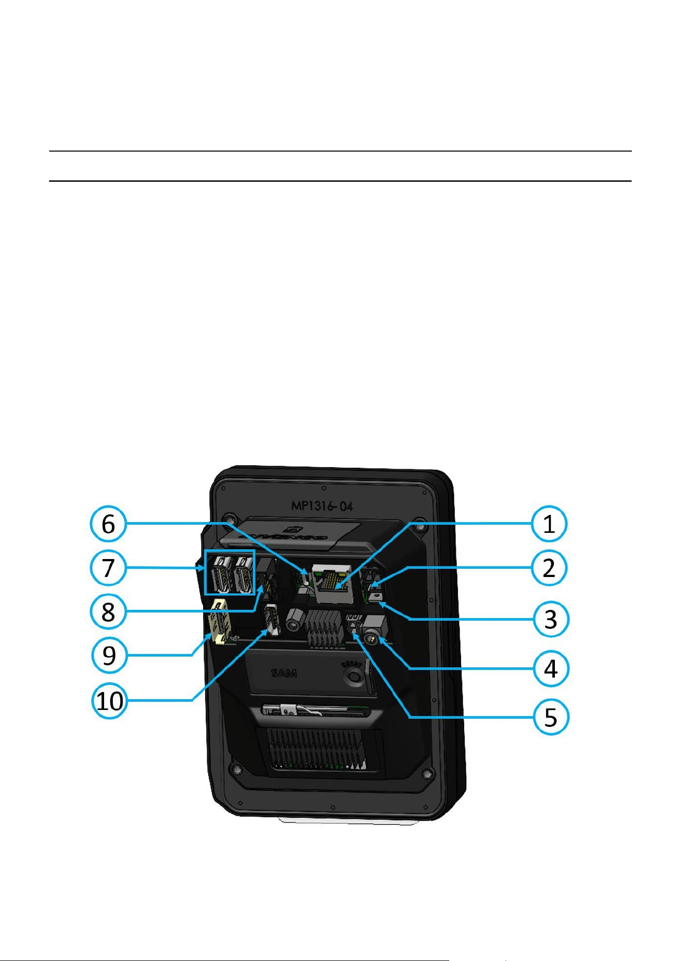
CHAPTER 11 – G6-500NFC Wiring
The G6-500NFC (A2-05) has the following seven hardware interfaces:
1. Ethernet 10/100Base.
2. DC Power Supply input.
3. Earth tab.
4. Audio Jack (mic-In/Line-Out).
5. Audio Output / External Speaker.
6. USB-C.
7. 2 x USB-A.
8. External Serial Connection / Printer.
9. External Display.
10. HDMI Output.
G6-500NFC (A2-05) - Connections
G6-500NFC User Guide, DCV-00660 S2 R06
Page | 27
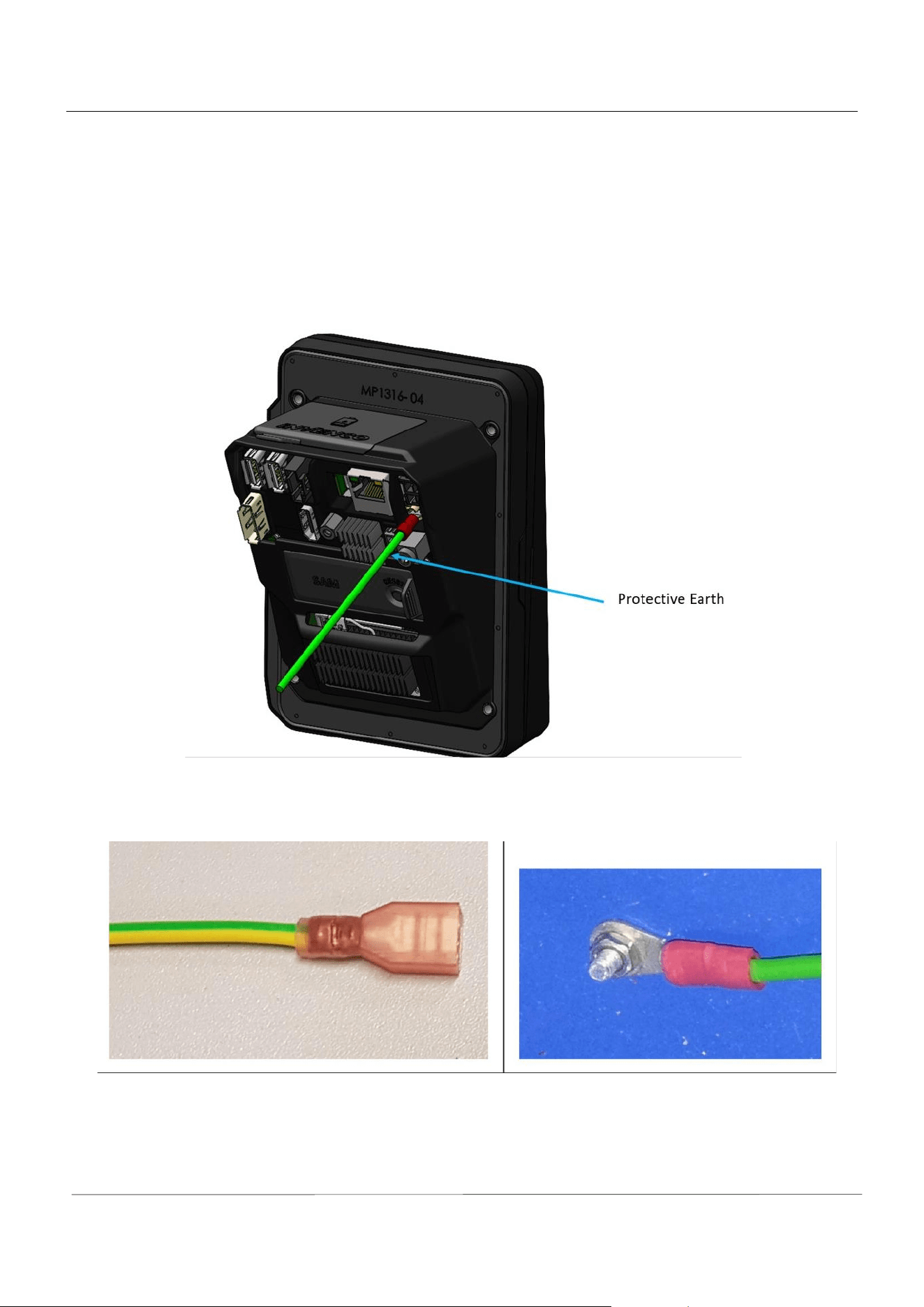
11.1. Protective Earth
The G6-500NFC (A2-05) is provided with an Earth Tab and is recommended to be earthed.
The tab must be connected to the pump (or cabinet) frame to provide protection from both power faults and static
discharges. The earth wire thickness must be minimum 1.5 mm2 (or 16awg) and both it and the earth stud must meet
local regulations.
Protective Earth
Protective Earth
G6-500NFC User Guide, DCV-00660 S2 R06
Page | 28
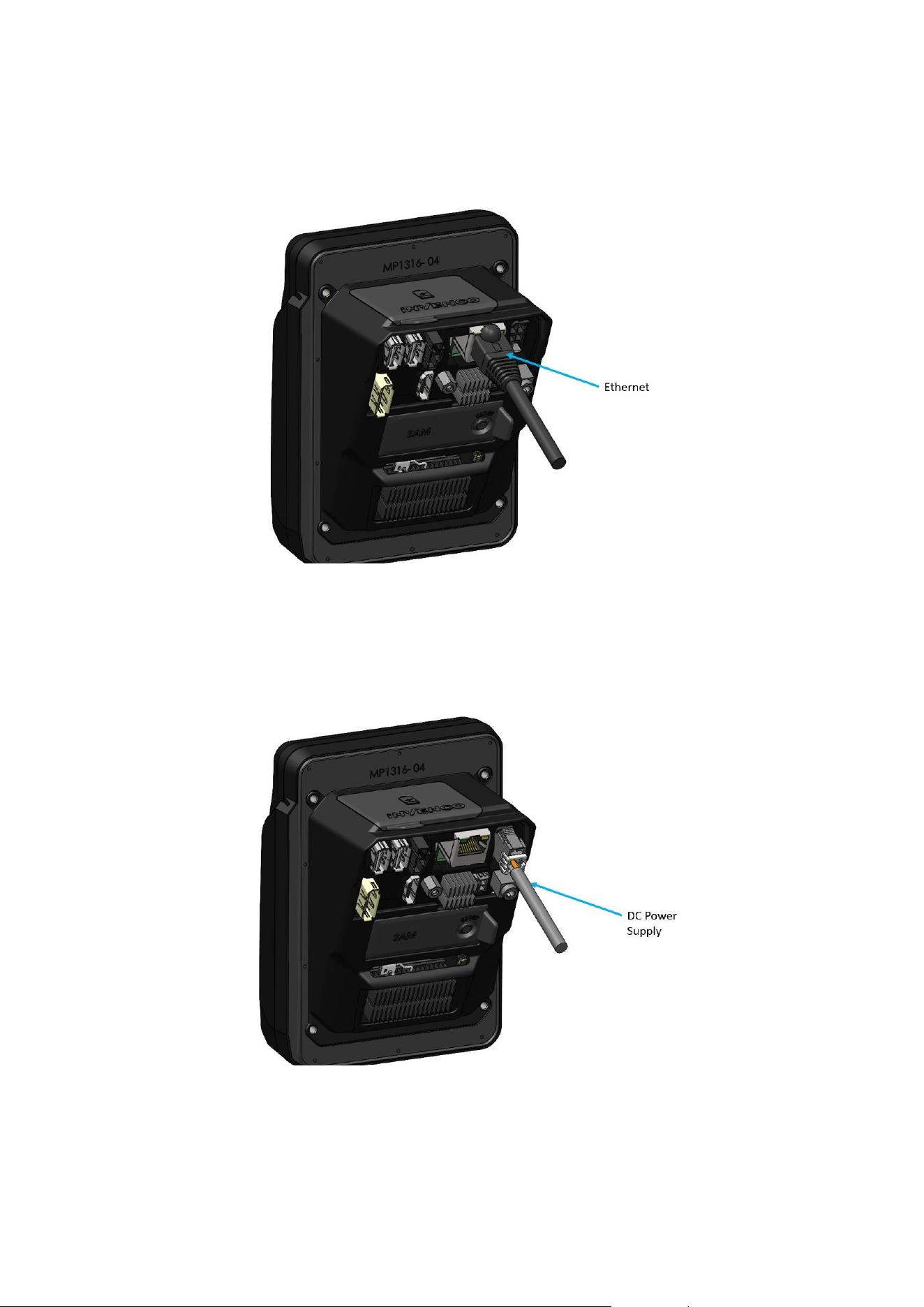
11.2. Ethernet LAN
The Ethernet cable (Ethernet 10/100 Base-T) is plugged into the correct connector on the rear of the G6-500NFC:
Ethernet Connection
11.3. DC Power IN
The low-voltage DC Cable is plugged into the correct connector on the rear of the G6-500NFC.
Power Supply
The low-voltage DC cable carries the part number EK0171, and it can be obtained from Invenco partner companies.

G6-500NFC User Guide, DCV-00660 S2 R06
Page | 29
CHAPTER 12 - Main Power Supply Wiring
Depending on the specific installation, the primary power supply connections require 24 V DC and an Earth
connection.
G6-500NFC User Guide, DCV-00660 S2 R06
Page | 30
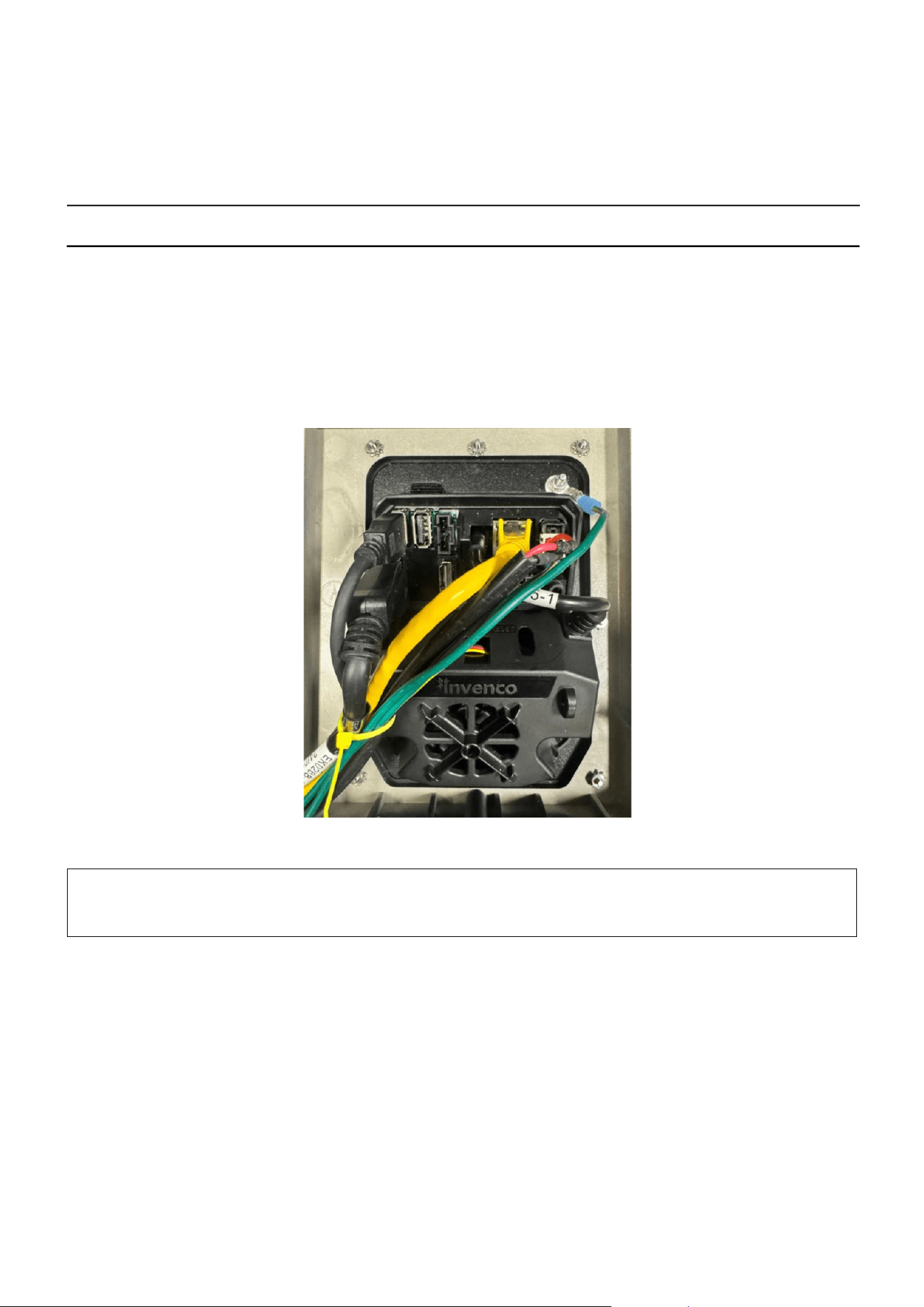
CHAPTER 13 - Wiring Completion
When all the cables have been installed, use cable ties to provide strain relief.
Ensure that all cables are tidy and cannot become snagged or pinched when the door of the cabinet is opened and
closed.
Note: Ensure the cables are kept clear of the A2-05 fan kit opening to allow proper ventilation.
WARNING:
Local regulations may also require that the installation is electrically tested and certified
BEFORE switch-on, and periodically over the life of the unit.
G6-500NFC User Guide, DCV-00660 S2 R06
Page | 31
CHAPTER 14 - First Power - Up
Once the installation is complete and the wiring is certified (if necessary), the main power can be switched on.
14.1. Normal Start-Up
The G6-500NFC takes a couple of minutes to complete its start-up phase.
During this, several standard information screens will display.
There may be other screens as well, depending on customer configuration.
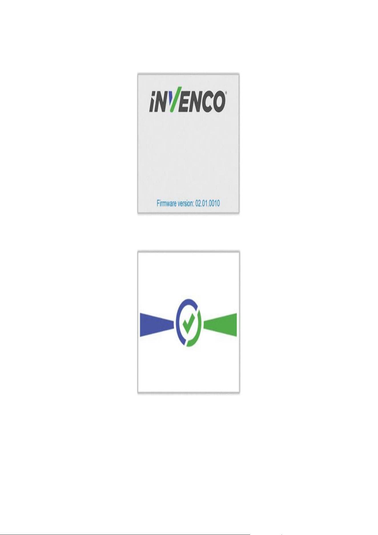
Start-up screen:
G6-500NFC Start up screen
G6-500NFC User Guide, DCV-00660 S2 R06
Page | 32
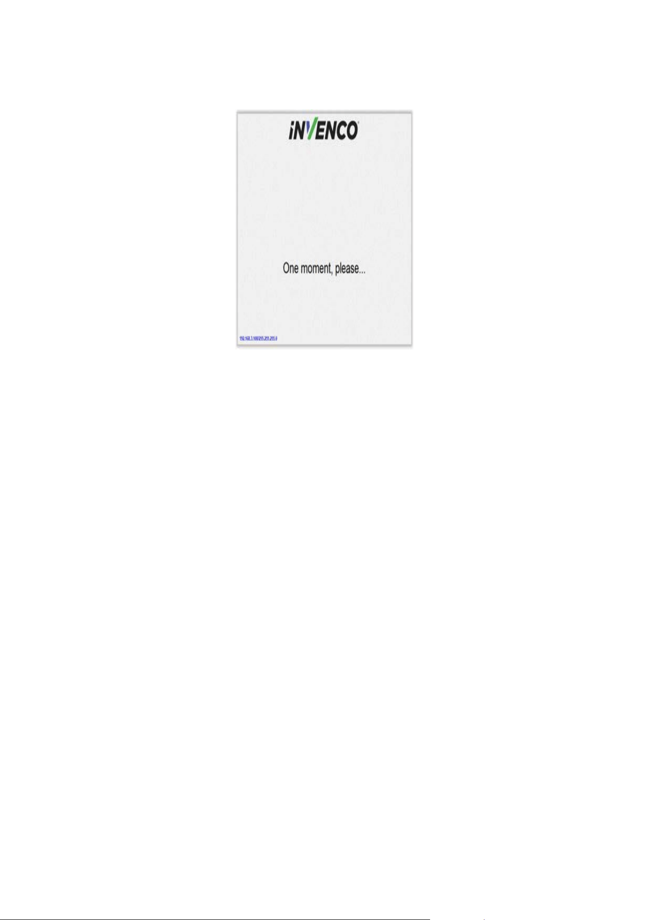
Connecting to Ethernet screen:
Trying to establish Ethernet connection.
When the terminal has successfully connected to the Ethernet LAN it will display the following screen:
Ethernet connection established.
After this the start-up will continue. The screens that are presented will vary depending on individual customer
configuration.
G6-500NFC User Guide, DCV-00660 S2 R06
I
Page | 33
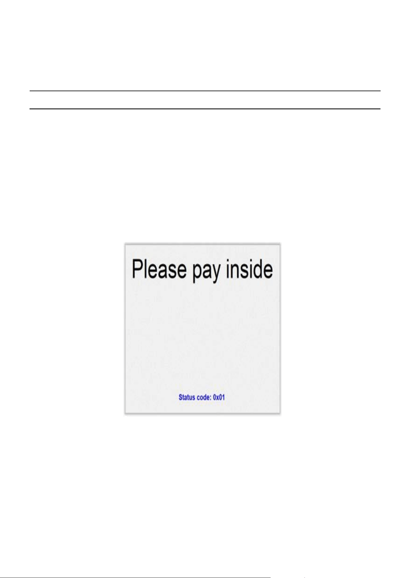
Service App settings are available.
14.2. Edit Configuration
If The G6-500NFC is not configured during staging or settings have changed, “edit configuration” option is available in the
service e app to make required changes.
G6-500NFC User Guide, DCV-00660 S2 R06
Page | 34
CHAPTER 15 - Tamper-Detection
The G6-500NFC is a secure device, and it contains various technologies that help it detect if someone tries to tamper
with it.
The terminal includes several tamper detection mechanisms such as temperature extremes, backup battery removal,
dis-assembly, and severe conditions, including mishandling or dropping the device may cause a tamper event.
If, on power-up or at any time when the G6-500NFC is powered, a tamper is detected, the G6-500NFC will
immediately lock out of “normal” operation and enter a “tampered” state. When this happens, the G6-500NFC will
not process any transactions and, depending on the nature of the tamper it may be almost completely
unresponsive.
If a tamper has been detected, after power-up the G6-500NFC will display this screen:
Tamper Detection
The lights in the Card Reader slot will flash RED at about five times per second (i.e., rapid) if a Destructive Tamper
has been detected:
A Destructive Tamper cannot be restored on-site and requires the G6-500NFC to be returned to the factory for
service/ repair.

G6-500NFC User Guide, DCV-00660 S2 R06
Page | 35
CHAPTER 16 - Basic Maintenance
16.1. Cleaning G6-500NFC (A2-05) Module
The G6-500NFC is designed to be low maintenance.
Daily cleaning:
Wipe with a soft damp cloth using only water.
If dirt or grime builds up:
• Use a diluted mild detergent and wipe with a soft cloth.
• Dry the screen using a lint-free or microfiber cloth.
• Use an air duster (air can) with a max 2mm diameter straw to flush debris out of the ICC card slot. Insert in
the slot, some wiggling might be required to ensure it is fully inserted. Blow air into the ICC area to clear out
any dust or particulates.
• Then insert a Magnetic Head Cleaning Case into the ICC card slot 3-5 time. Repeat this on the MSR head.
Things to watch out for:
• Always clean off excess detergent.
• Do not use a high-pressure water stream to clean your G6-500NFC. Water pressure may damage the card
reader.
• Do not rub the display if it is dry – dust or dirt can scratch the anti-reflective coating.
• Do not use petroleum based solvent cleaners, they will damage the surface and shorten the life of your
product.
16.2. A2-05 Fan Kit Maintenance
The FlexPay 6 A2‑05 Fan Kit may only be maintained by authorized service personnel, as the fan is installed on the
rear of the G6-500NFC unit behind the dispenser door and is not accessible to normal users. Basic maintenance
checks include the following:
• Ensure the USB-C fan and its connector are free from visible damage.
• Check that the fan blades can rotate freely without obstruction.
• If the fan appears dirty but undamaged, clean it gently using a soft brush or an air duster (air can) with a max
2mm diameter straw to remove dust and debris. Avoid using liquids or solvents.

G6-500NFC User Guide, DCV-00660 S2 R06
Page | 36
CHAPTER 17 - Security Checks
17.1. Built in Security
The G6-500NFC has built-in tamper detections, but you should also regularly check your G6-500NFC for signs of
tampering or alteration.
If it looks different to normal, then there could be a hidden camera or PIN-disclosing bug – you might have a problem
that threatens customer security.
17.2. Extra Security Checks
Use this section to carry out extra security checks, and if you’re still not sure about your G6-500NFC then call
Customer Support.
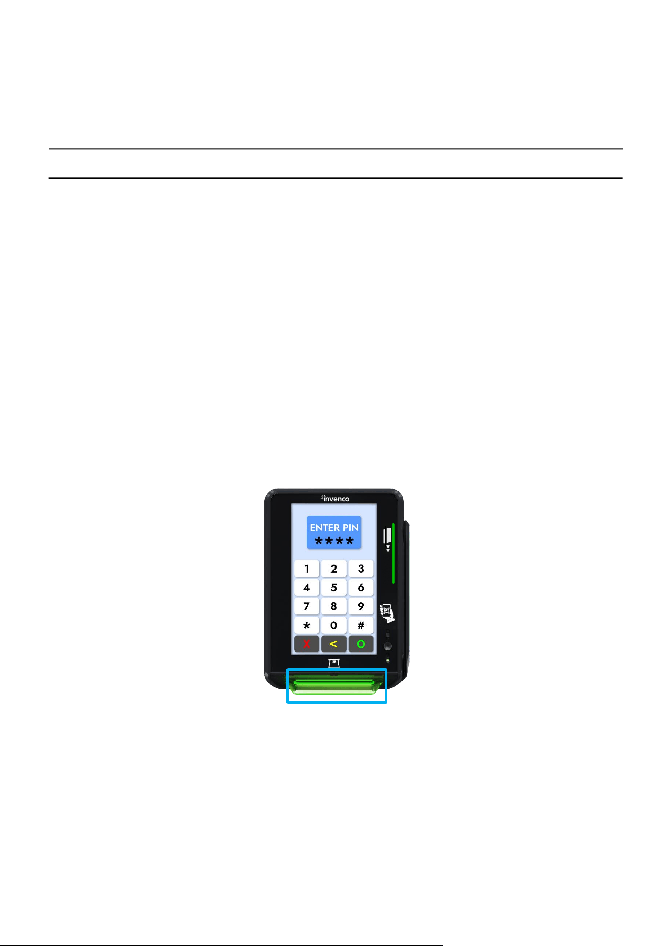
The following pages include photos and descriptions of what the G6-500NFC components should look
like. If your G6-500NFC looks different in any way, DO NOT use it.
Follow the escalation procedure below if you have any doubts at all about the integrity of your OPT.
17.3. Escalation
If you think that your G6-500NFC has been tampered with:
• Contact the vendor’s security person or support desk immediately.
• If neither of those contacts are available, contact Invenco’s security officer at the Auckland address detailed at the
end of this document.
• Notify local law-enforcement immediately.
G6-500NFC User Guide, DCV-00660 S2 R06
Page | 37
CHAPTER 18 - Inspection
The G6-500NFC has a smooth finish with an uninterrupted surface. Any breaks or uneven surfaces should be
inspected as a potential security concern.
18.1. Card-Reader Slot
What to check for:
• Are there any wires of any kind coming out of the Card Slot?
There should be no visible wires at all on or around the Card Slot.
• Is the OPT finish uninterrupted and consistent across the Card Slot?
There should be no cracks, holes or bumps of any kind.
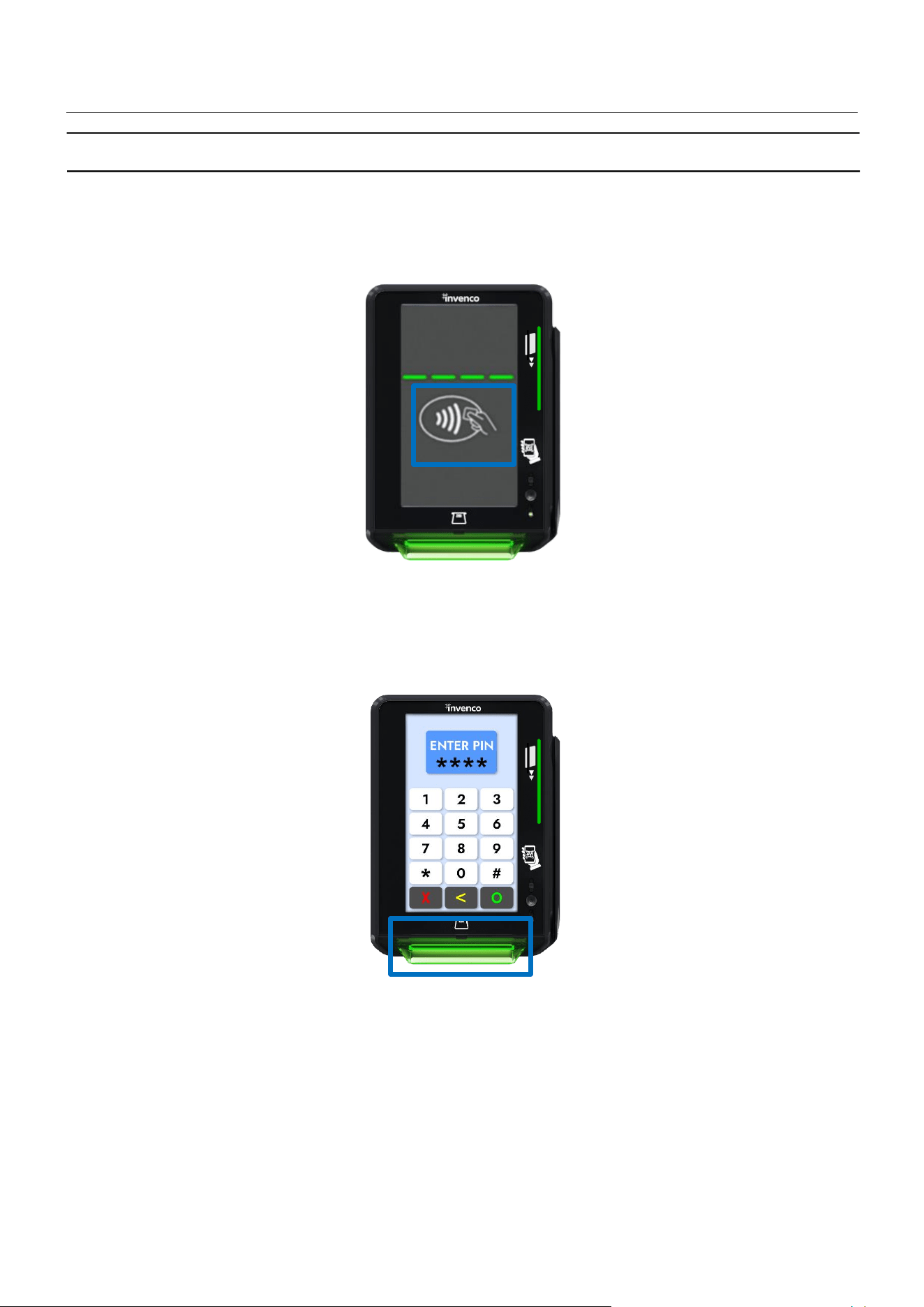
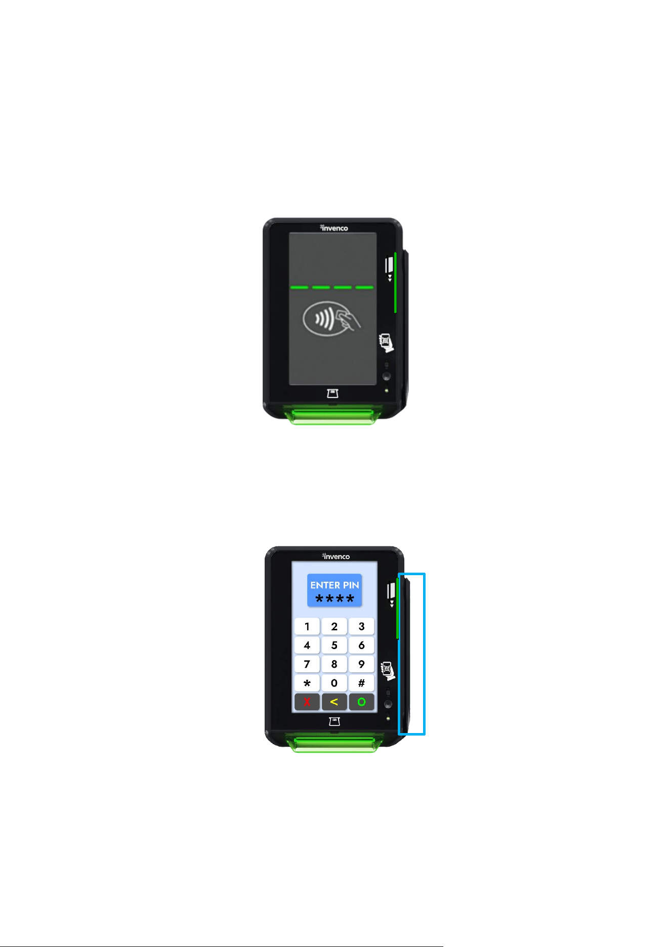
• Does the card slot acceptor light:
Flash green when it is ready and waiting to accept a card?
Front of Card Reader Slot
G6-500NFC User Guide, DCV-00660 S2 R06
Page | 38
18.2. Contactless Reader
• Does the Contactless Reader:
Show one steady green light when ready to accept a payment?
When the contactless reader is armed, there should be a logo and simulated LEDs displayed similar to that shown in
the figure below. This display may be customized for different applications.
Front of Contactless Reader
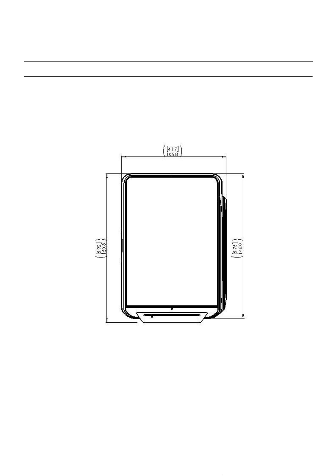
18.3. Magstripe
Magstripe

G6-500NFC User Guide, DCV-00660 S2 R06
Page | 39
CHAPTER 19 - Removal & Re installation
19.1. How to Uninstall a G6-500NFC Module and A2-05 Fan Kit
Step Instructions
1. To remove an existing Invenco Outdoor Payment Terminal (OPT) and the A2-05 Fan Kit:
2. Make sure that the terminal is not in use.
3. Open the enclosure door.
4. Switch off the mains power.
5. Carefully cut the cable ties holding cables in place to the existing OPT. Do not cut any other cable
ties.
6. Remove the ground wire and unplug the Ethernet and low-voltage power cables.
7. Unscrew the 4 x M4 screws holding the OPT and the A2-05 Fan Kit to the door.
9. Carefully lift the OPT along with the fan kit out of the enclosure and package it for disposal or
return.
19.2. How to Reinstall a G6-500NFC module and A2-05 Fan Kit
Step Instructions
1. Prepare the terminal by removing any traces of existing sealing gasket with a soft scraper and/or
isopropyl alcohol.
2. Remove the G6-500NFC and A2-05 Fan Kit from its packaging and inspect it for damage.
3. Place the G6-500NFC face down on a soft, clean surface, and attach the new sealing gasket.
4. Place the G6-500NFC carefully into the cut-out in the door and align it with the screw-
holes (or brackets if there has been a previous retrofit).
5. Loosely place all the screws, check that the G6-500NFC is properly aligned with any
features on the pump or cabinet door, then tighten the top two screws to a torque of 0.65
Nm to 0.70 Nm. For the bottom two screws, partially insert until the head is
approximately 3mm from the panel and its fully assembled position.
6. Position the A2-05 fan kit, aligning the 2 slots below the two bottom partially installed screws,
slide the kit upwards as far as it can go ensuring it is correctly aligned with screw positions.
7. While pulling the assembly up, tighten the screws to a torque of 0.65 Nm to 0.70 Nm
to securely fasten the Fan Kit to the G6-500NFC module.
8. Insert the USB-C connector from the A2-05 Fan Kit into the USB-C port located at the back of the
A2-05 unit.
Note: When plugging in the USB-C, it may be incorrectly inserted on the right side without
actually connecting. The installers should visibly confirm the connection.
9. Plug in the power cable and the LAN cable.
10. Connect the Ground wire.
11. Use new cable ties to gather all cables together, then close the door making sure not to
snag or pinch any of the cables.
12. Check that the G6-500NFC has come Online correctly and that the fan is running , then
close the cabinet/pump door.
13. If this is a replacement G6-500NFC (i.e. not the same one removed) you may need to configure
it for proper operation.
G6-500NFC User Guide, DCV-00660 S2 R06
Page | 40
CHAPTER 20 - Drawings
20.1. Dimensions
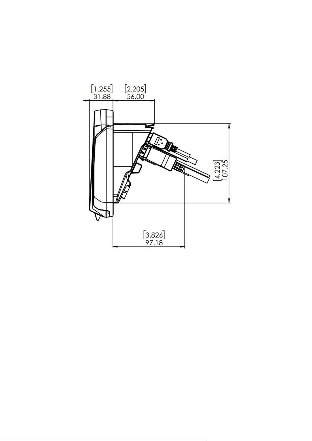
Dimensions G6-500NFC
Dimensions G6-500NFC Module Front View
G6-500NFC User Guide, DCV-00660 S2 R06
Page | 41
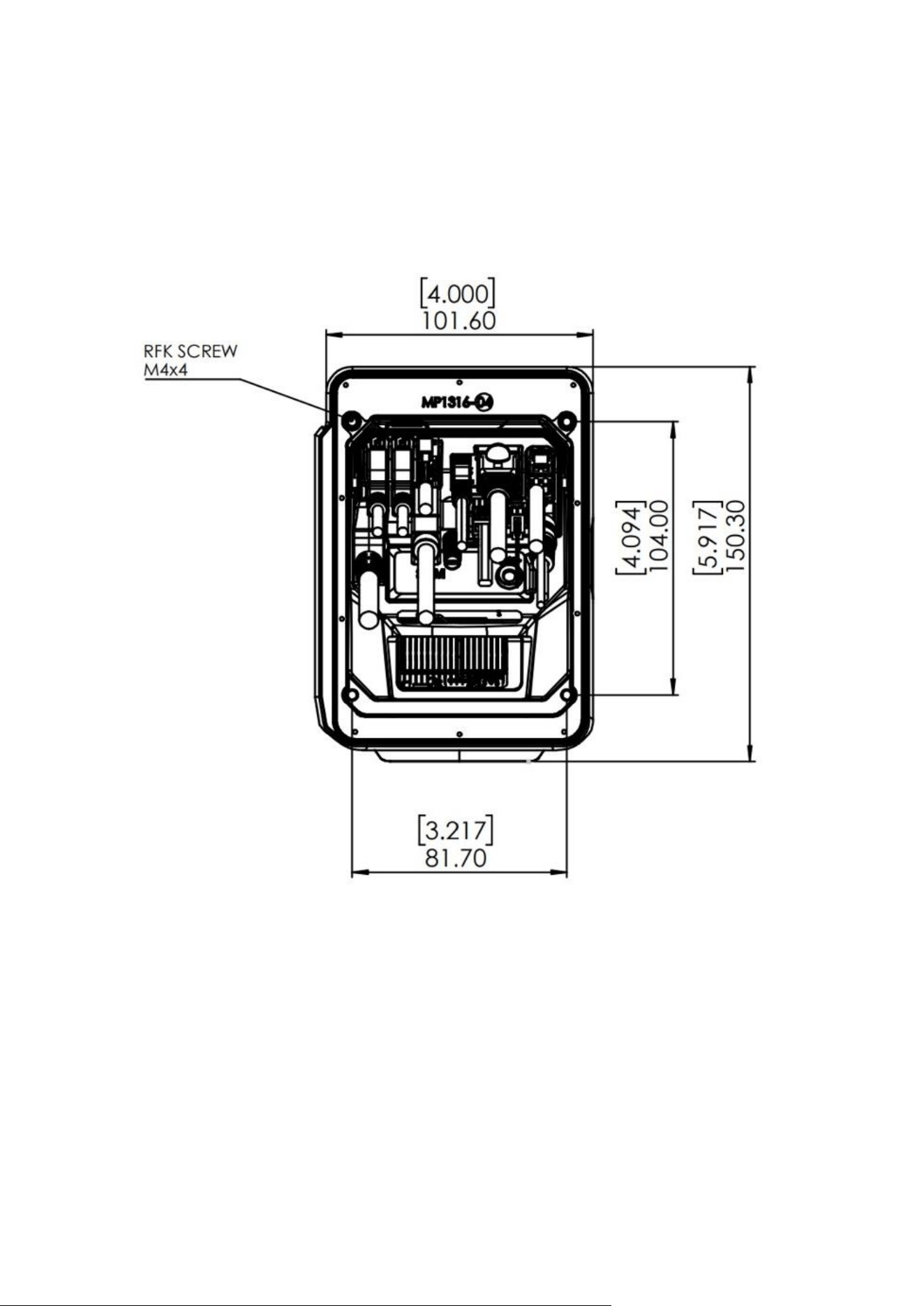
Dimensions G6-500NFC Side View
G6-500NFC User Guide, DCV-00660 S2 R06
Page | 42
Dimensions G6-500NFC Rear View & Mounting Points

G6-500NFC User Guide, DCV-00660 S2 R06
Page | 43
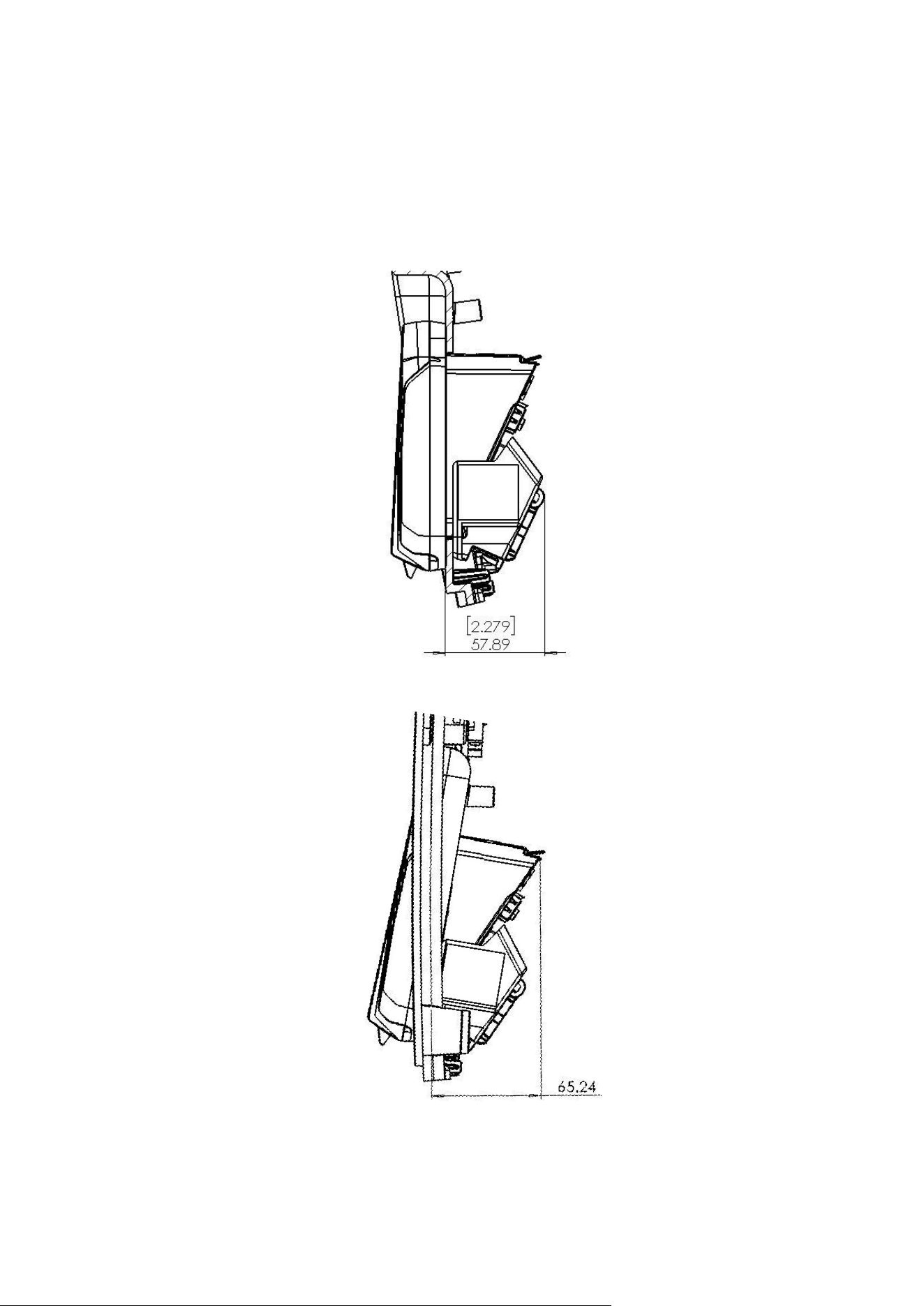
Dimensions A2-05 Fan Kit
Dimensions A2-05 Fan Kit Front View Dimensions A2-05 Fan Kit Side View
Dimensions A2-05 Fan Kit Side View
G6-500NFC User Guide, DCV-00660 S2 R06
Page | 44
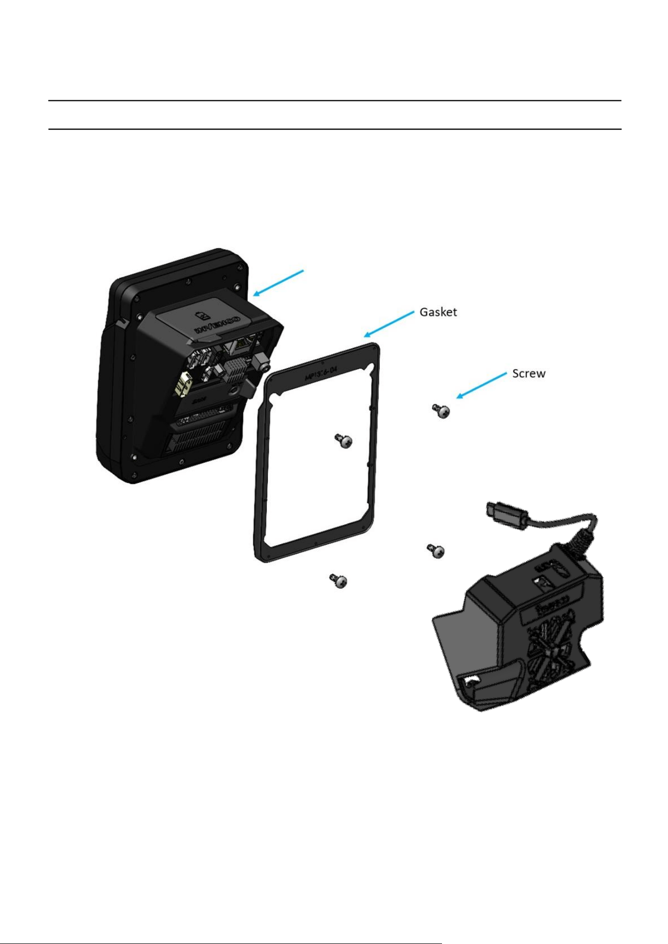
Dimensions G6-500NFC fitted with A2-05 Fan Kit
Dimensions G6-500NFC Fitted With A2-05 Fan Kit on Alternative Mounting Panel
G6-500NFC User Guide, DCV-00660 S2 R06
Page | 45
CHAPTER 21 - Mounting - New Installation
Exploded View, Mounting to Panel
G6-500NFC
G6-500NFC User Guide, DCV-00660 S2 R06
Page | 46
Panel Cutout Detail, G6-500NFC
G6-500NFC User Guide, DCV-00660 S2 R06
Page | 47
CHAPTER 22 - Typical Wiring
The schematic below shows the standard and typical wiring for the
G6-500NFC. We recommend that you use this wiring for safety and correct
performance.
G6-500NFC Wiring Diagram
AC-DC Power Supply
(AC)
Ethernet
EK0171 (Recommended)
-V
-V
24VCD Output
Inline Fuse
3.15A Slo-Blo
Ferrite
Cabinet Earth Stud
To Earth Stud On OPT
Mains Input
Connections to Mains
L
N
E
-V
DC Connection

