FibreSeeker3
Product Description

i
Table of Contents
Chapter One PRINTER INTERDUCTION ............................................................ 1
1.1 Specifications ................................................................................................................ 1
1.2 Components .................................................................................................................. 3
1.2.1 Front View .............................................................................................................. 3
1.2.2 Back View ................................................................................................................ 3
1.2.3 CFC Dual-Nozzle Design.................................................................................... 4
1.3 Accessories .................................................................................................................... 6
Chapter Two UNBOXING STEPS ......................................................................... 7
2.1 Preparations .................................................................................................................. 7
2.2 Unpacking and Disassembly .................................................................................... 9
2.3 Installing the Screen and Bracket ....................................................................... 12
Chapter Three HUMAN INTERFACE (HMI) .................................................. 13
3.1 Home Page.................................................................................................................. 13
3.2 Setting .......................................................................................................................... 14
3.2.1 Control .................................................................................................................. 15
3.2.2 Calibration--Print Calibration ....................................................................... 18
3.2.3 Toolbox ................................................................................................................. 19

ii
3.2.4 Others .................................................................................................................... 20
3.2.4 More Settings ..................................................................................................... 21
3.3 Materials ...................................................................................................................... 22
3.4 Printing File ................................................................................................................. 23
3.5 Workflow ..................................................................................................................... 25
Chapter Four ADDITIONAL NOTES ................................................................. 26
4.1 Attention ...................................................................................................................... 26
4.2 Basic Slicing ................................................................................................................ 27
4.3 Maintenance ............................................................................................................... 28
4.4 Support ........................................................................................................................ 29
01
Chapter One PRINTER INTERDUCTION
1.1 Specications
Technology
Fibre
Composite Fibre Co-extrusion
(CFC)
Plastic
Fused Filament Fabrication
(FFF)
Printer Body
Device Dimensions
615 x 595 x 540 mm3
Device Weight
32 kg
Build Volume (W×D×H)
300×300×245mm3
Outer Frame
Plastic and Glass
Printing Accuracy
±0.2mm
Minimum Layer
Thickness
50μm
Printhead
Hotend
All Metal
Nozzle
Hardened Steel
Max FFF Nozzle
Temperature
350°C
Max CFC Nozzle
Temperature
350°C
FFF Nozzle Diameter
0.4mm
CFC Nozzle Diameter
0.7mm
Fibre Cutter
Built-in
FFF Filament Diameter
1.75 mm
Chamber
Active Chamber Heating
Suppoed
Max Temperature
65°C
Heatbed
Suppoed Build Plate
Type
Flexible High-Temperature
Base
Max Heatbed
Temperature
120°C
02
Bed-Leveling
Fully Automatic Leveling
Material
Storage
FFF Plastic
Back Hangers
CFC Fibre
Embedded Chamber
Speed
Max FFF Speed
500mm/s
Max CFC Speed
20cc/h
Cooling
Pa Cooling Fan
Open Loop Control
Cooling Fan for Hotend
Closed Loop Control
Main Control Board Fan
Closed Loop Control
Suppoed
Filament Type
FFF Plastic
PLA, PETG, PC,
PACF, PETGF
CFC Fibre
X-CCF, X-CGF
Composite Tensile
Strength
Up to 900 MPa
Electronics
Control Screen
5-inch Touchscreen
Storage
32G BEMMC
Control Inteace
Touchscreen & PC App
Sensors
Live View Camera
Built-in; 1920 *1080
Plastic Breakage Sensor
Suppoed
Plastic Clogging Sensor
Suppoed
Fiber Breakage Sensor
Suppoed
Fiber Clogging Sensor
Suppoed
Software
Slicer
Rocket Slicer (FFF+CFC)
Operating System
Windows, Mac
Data Formats
Compatible with STL, STP,3MF
Electrical
Requirements
Voltage
90-132V, 50/60Hz,
176-264V, 50/60Hz
Max Power
1650W@110V; 2200W@220V
Average Power
1650W@110V; 2200W@220V
03
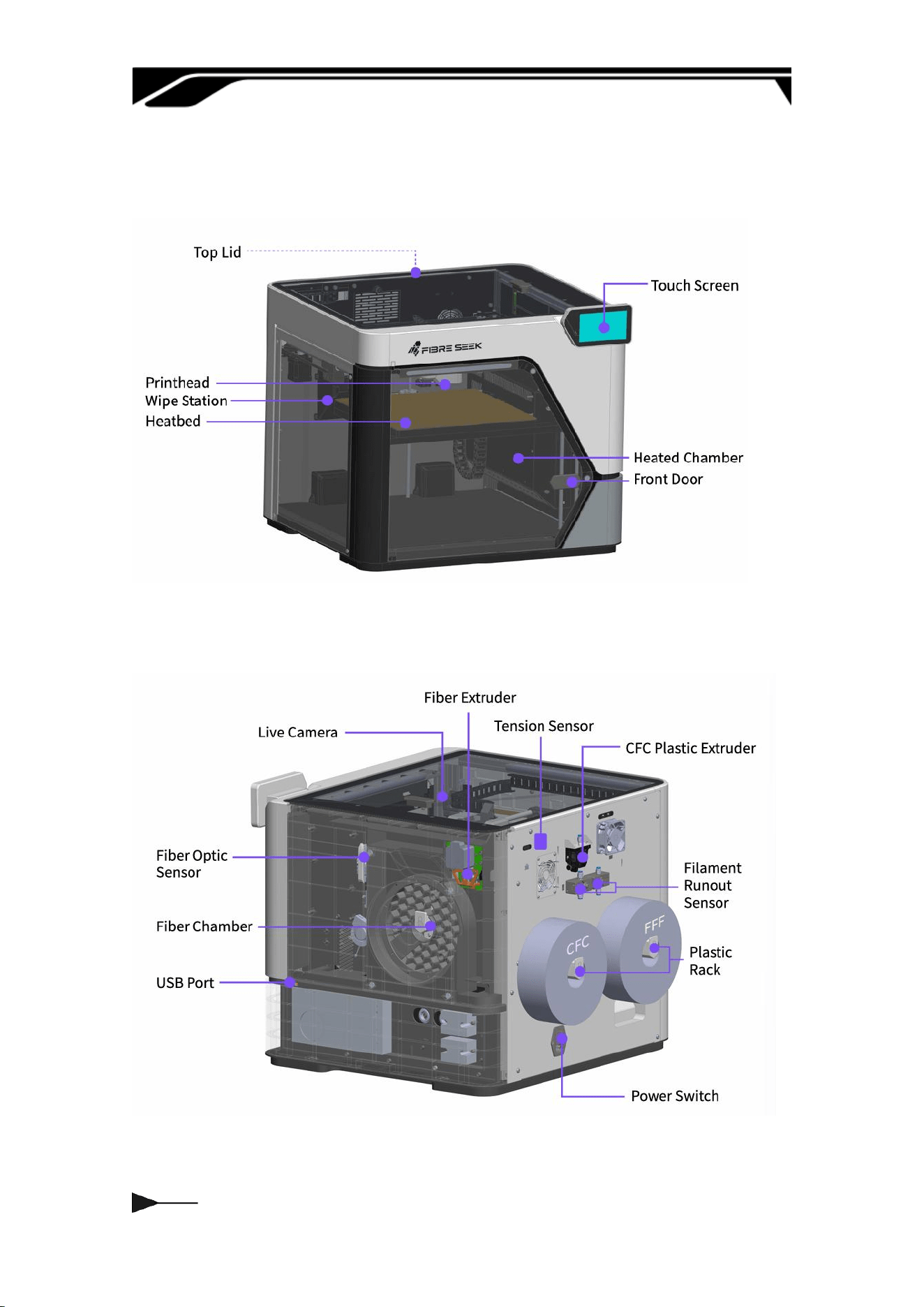
1.2 Components
1.2.1 Front View
1.2.2 Back View
04
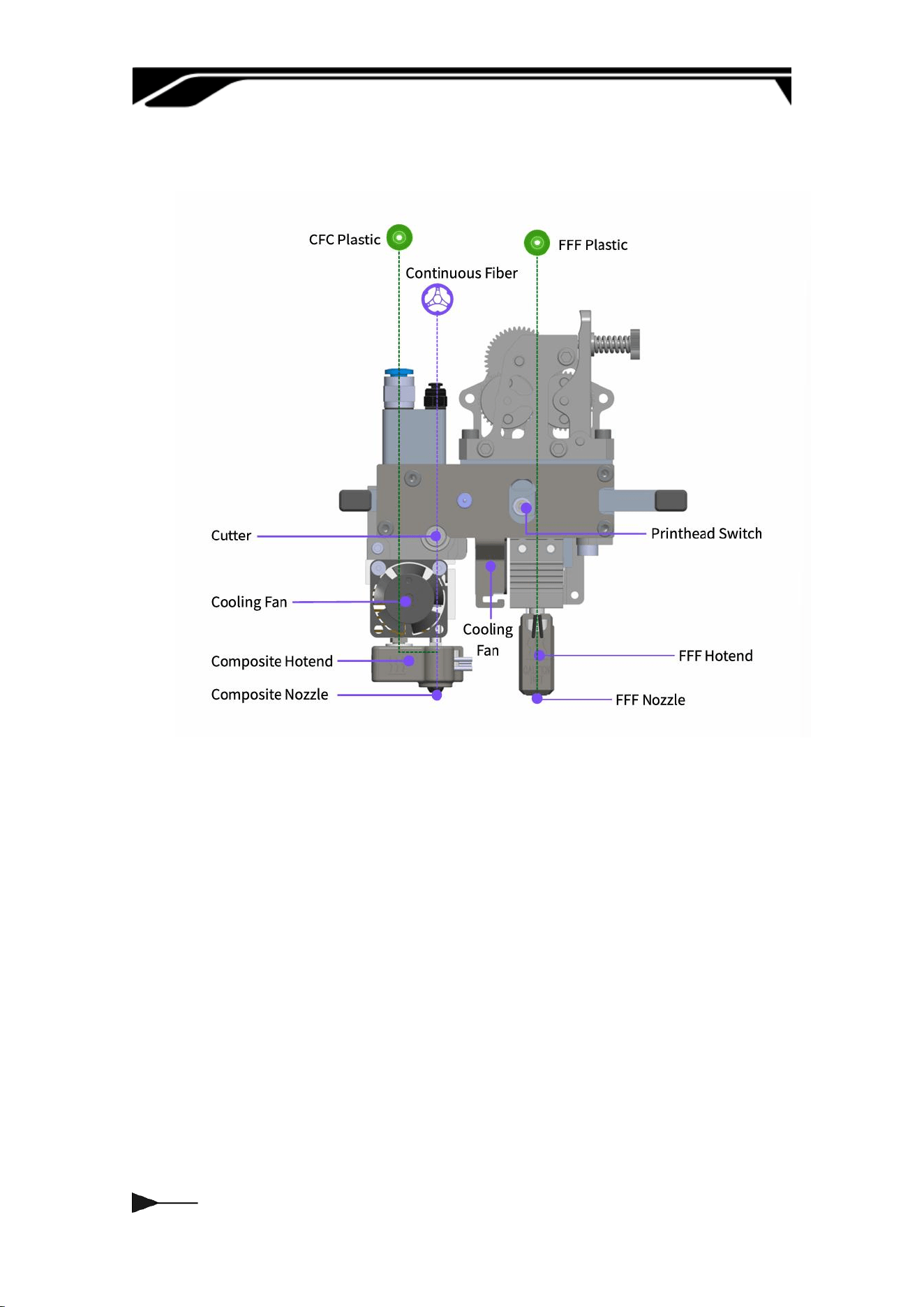
1.2.3 CFC Dual-Nozzle Design
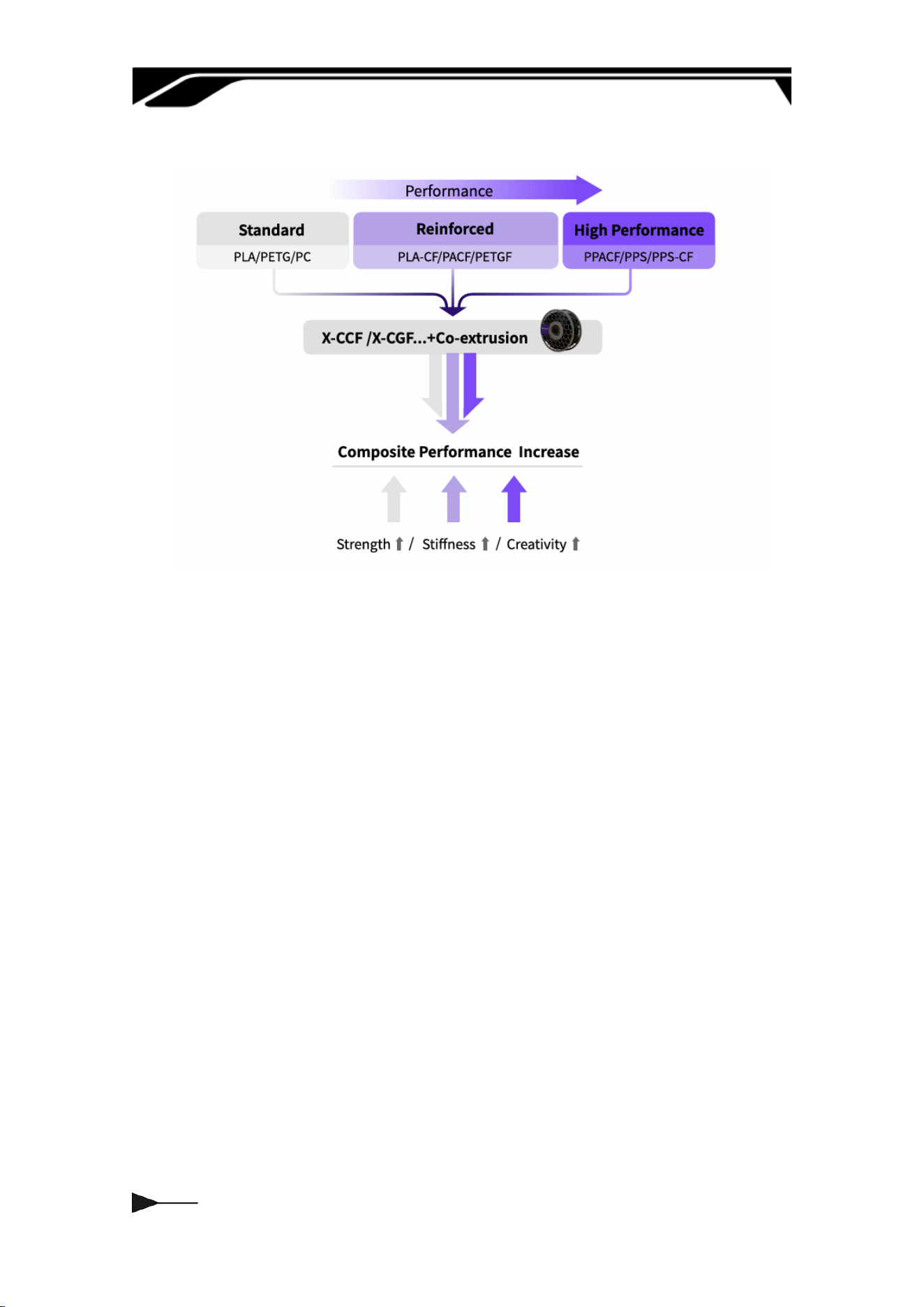
Materials
FFF Plastic: PLA, PETG, PC, PACF, PETGF, ABS, ASA, PPACF, PPSCF...
CFC Fibre: X-CCF, X-CGF...
CFC Plastic: PLA, PETG, PA...
05
X-CCF:
X-CCF is a continuous carbon ber lament impregnated with thermoset resin.
It features a ber volume fraction of approximately 60%. It combines
exceptional tensile strength with low density, and boasts excellent printability.
06
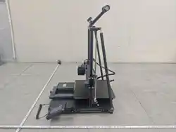
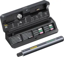
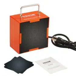
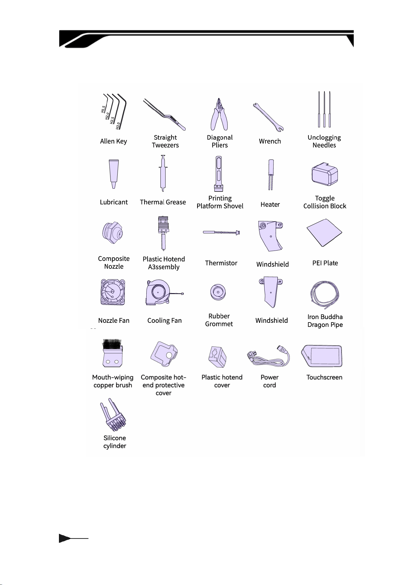
1.3 Accessories
07
Chapter Two UNBOXING STEPS
2.1 Preparations
1. Environmental Conditions
Select a at and stable load-bearing desktop;
maintain an ambient temperature of 10°C–30°C
and humidity of 30%–60%, avoiding extreme
environments and direct sunlight; connect to a
stable, grounded AC power source according to
your local region, and keep away from
ammable, explosive, dusty, or corrosive
materials.
2. Host Conguration
Windows 10 or later; Mac OS X v10.15 or later
— Intel® Core 2 or AMD Athlon® 64 processor; 2
GHz or faster processor — 8 GB of RAM
recommended (4 GB minimum) — 2.0 GB or
more of available hard-disk space.
Download address: Fibreseeker 3 – Fibreseek |
The World's First Personal Continuous Fibre 3D
Printer
3. Tool Preparation
Prepare scissors, a utility knife, and cut-
resistant gloves for unboxing, along with the
included hex keys, screws, and other assembly
tools; also prepare the printer unit, laments,
power cable, lament spool holder, screen, and
other original accessories, checking in advance
to ensure no pas are missing or damaged.

08
4. Installation Check, Estimated Time &
Precautions
After installation, ensure the lament spool
holder is securely assembled, the screen cables
are properly connected, and the software is
correctly congured; the estimated installation
time is 10–30 minutes; during operation, ensure
the power is disconnected and avoid touching
high temperature components. Strictly follow
the manual for assembly and ensure all
accessories are properly installed. Once
installation is complete, a brief d-run
movement test can be peormed; proceed with
formal printing only after conrming the
equipment operates without abnormal noise or
error messages.
09
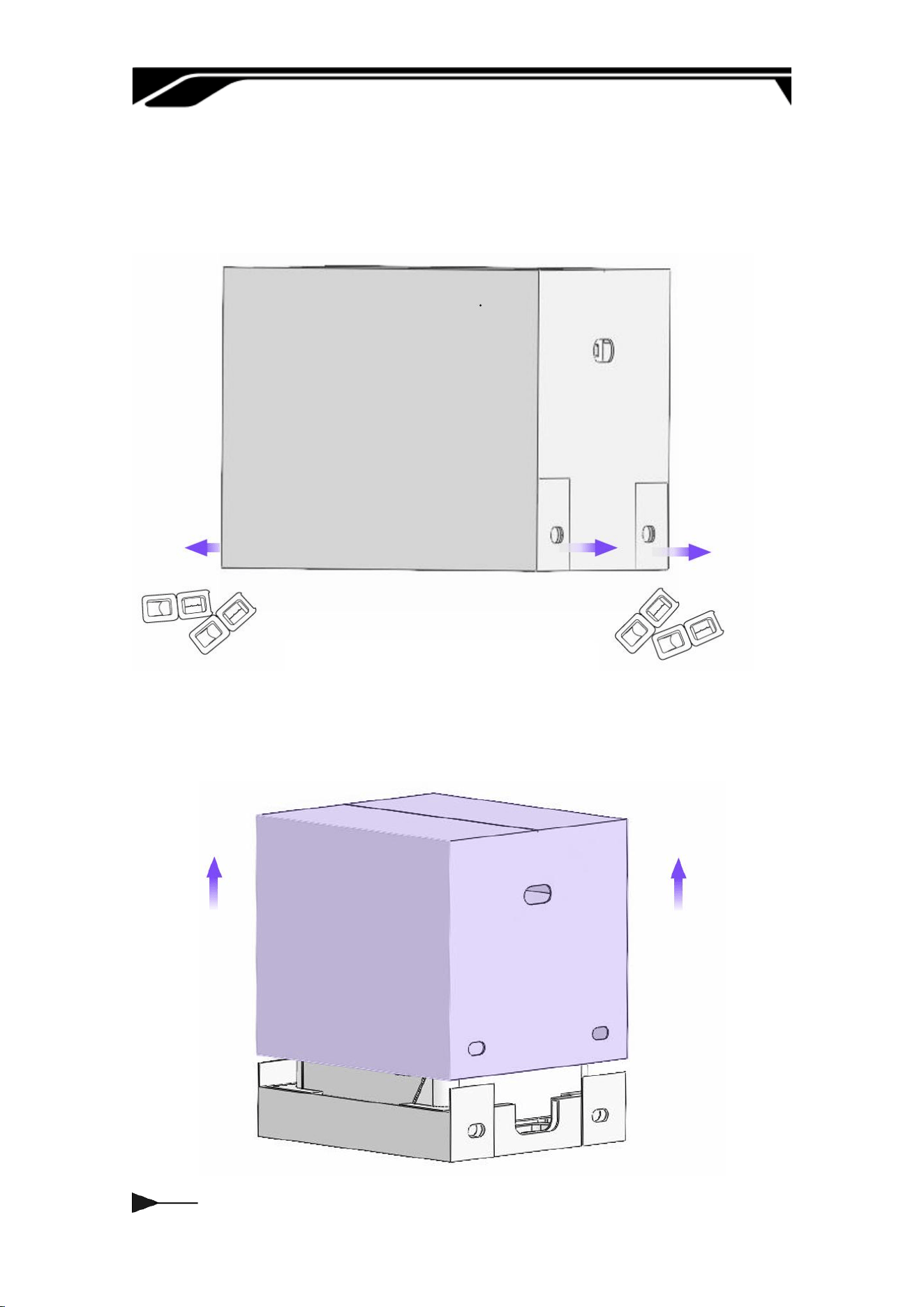
2.2 Unpacking and Disassembly
a. Dismantle the bottom fastener of the caon, remove the rest of the xing
bag, etc.
b. Remove caons slowly from the bottom to the top to prevent bumping the
machine.
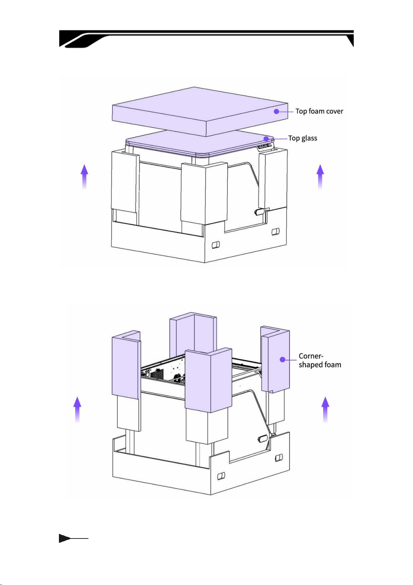
010
c. Remove the top foam and take o the top glass.
d. Remove the four-corner pillar foam.
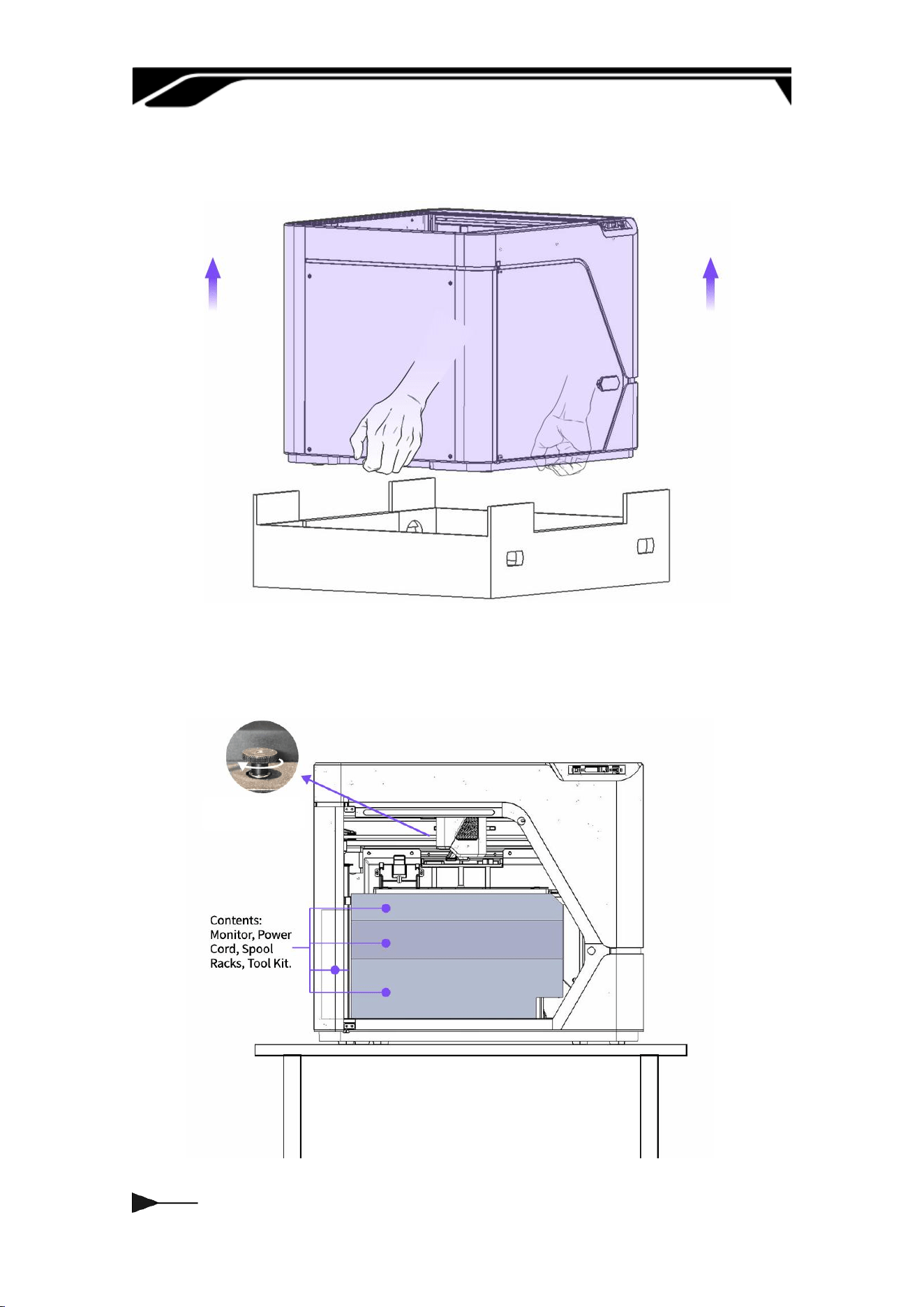
011
e. Keep the bottom of the caon still, two people lift out the printer, place the
printer on a at suace.
f. Turn clockwise twice.
g. Take out the inner packaging from top to bottom.
012
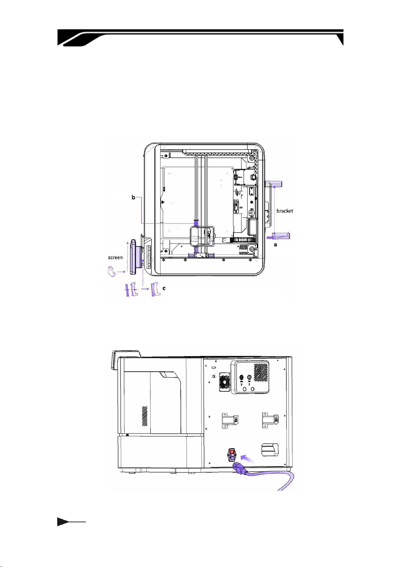
2.3 Installing the Screen and Bracket
a. Screw the Racks.
b. Remove the latch.
c. Flip the hinge up, align with the locating pin, and lock the display in place as
shown.
d. Take the power cord out of the accesso box and connect it to the machine
to turn it on.
013
Chapter Three HUMAN INTERFACE
(HMI)
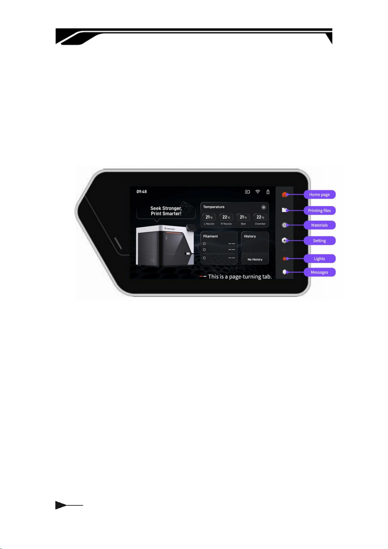
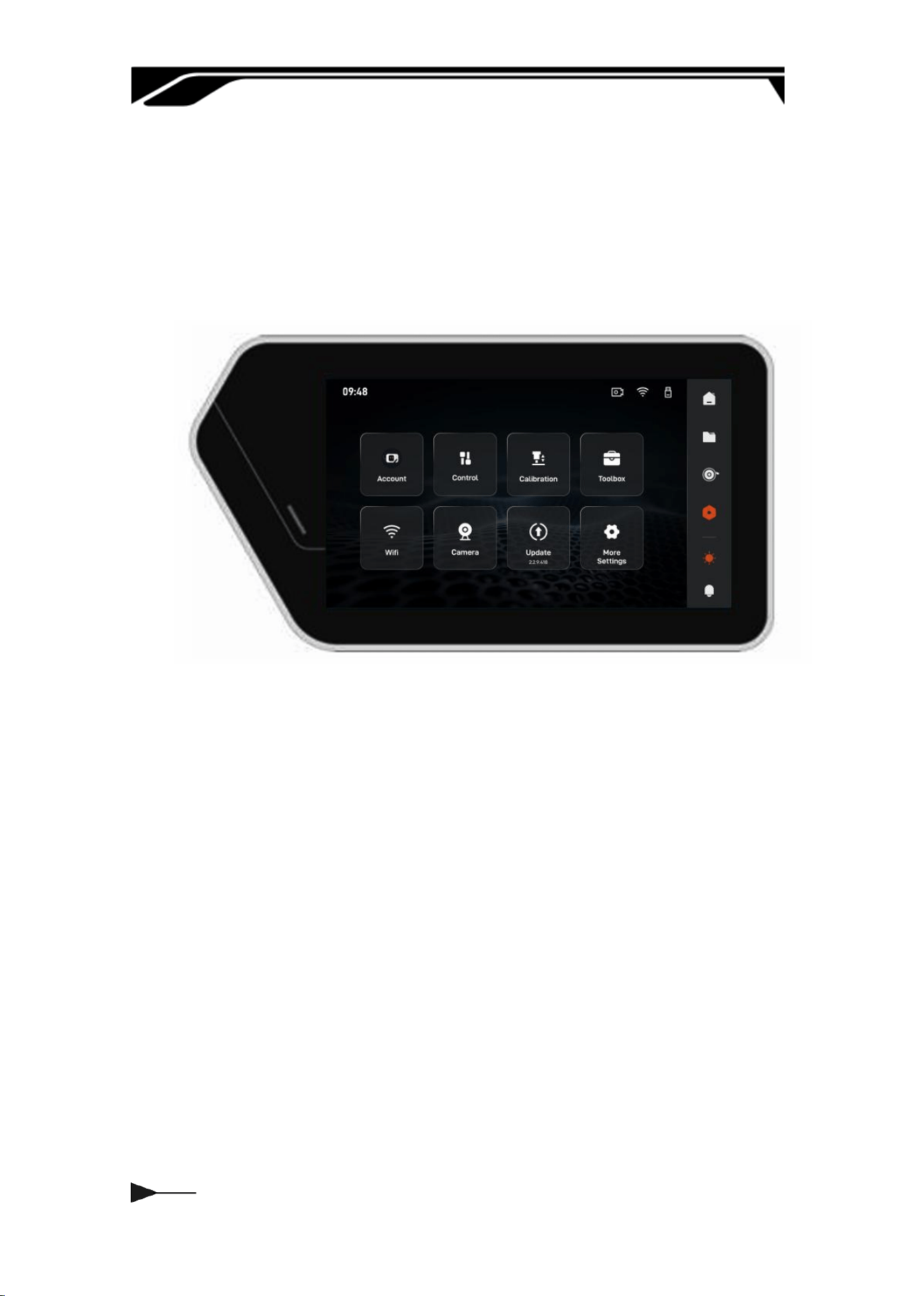
3.1 Home Page
After turning on the device, select the language in sequence, connect to Wi-Fi
and peorm device calibration, and the home screen will be displayed…
The home screen consists of two pages. The rst page includes the LOGO,
Temperature, Material, and File sections, while the second page provides
access to frequently used functions.
014
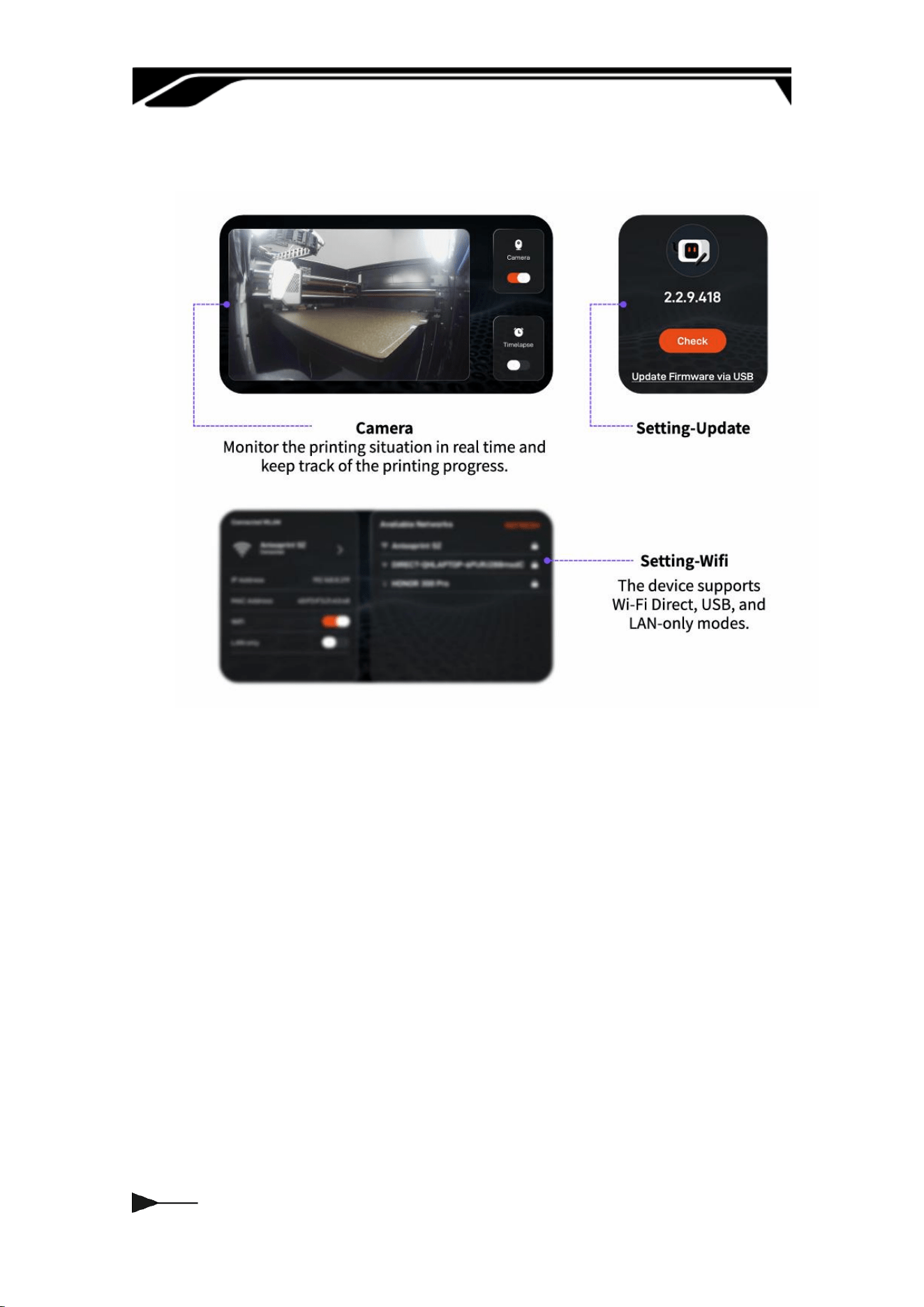
3.2 Setting
Through the sidebar settings menu, below are explanations of some key
functions. It suppos eight core functions: account, control, calibration,
toolbox, WIFI, camera, updates, and more settings, allowing users to customize
the printer's operating parameters according to their needs.
015
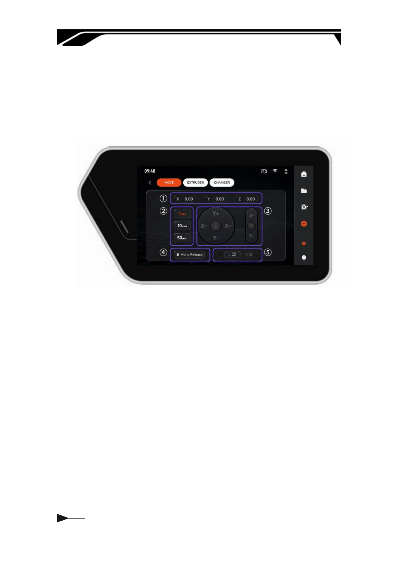
3.2.1 Control
This inteace is the core interactive inteace for device motion control,
integrating three-axis coordinate display, manual displacement control, motor
status management, and printhead switching.
① Real-time three-axis coordinate display area
② Movement step selection area
③ Three-axis manual movement and homing area
④ Motor release control area
⑤ Printhead switching area
016
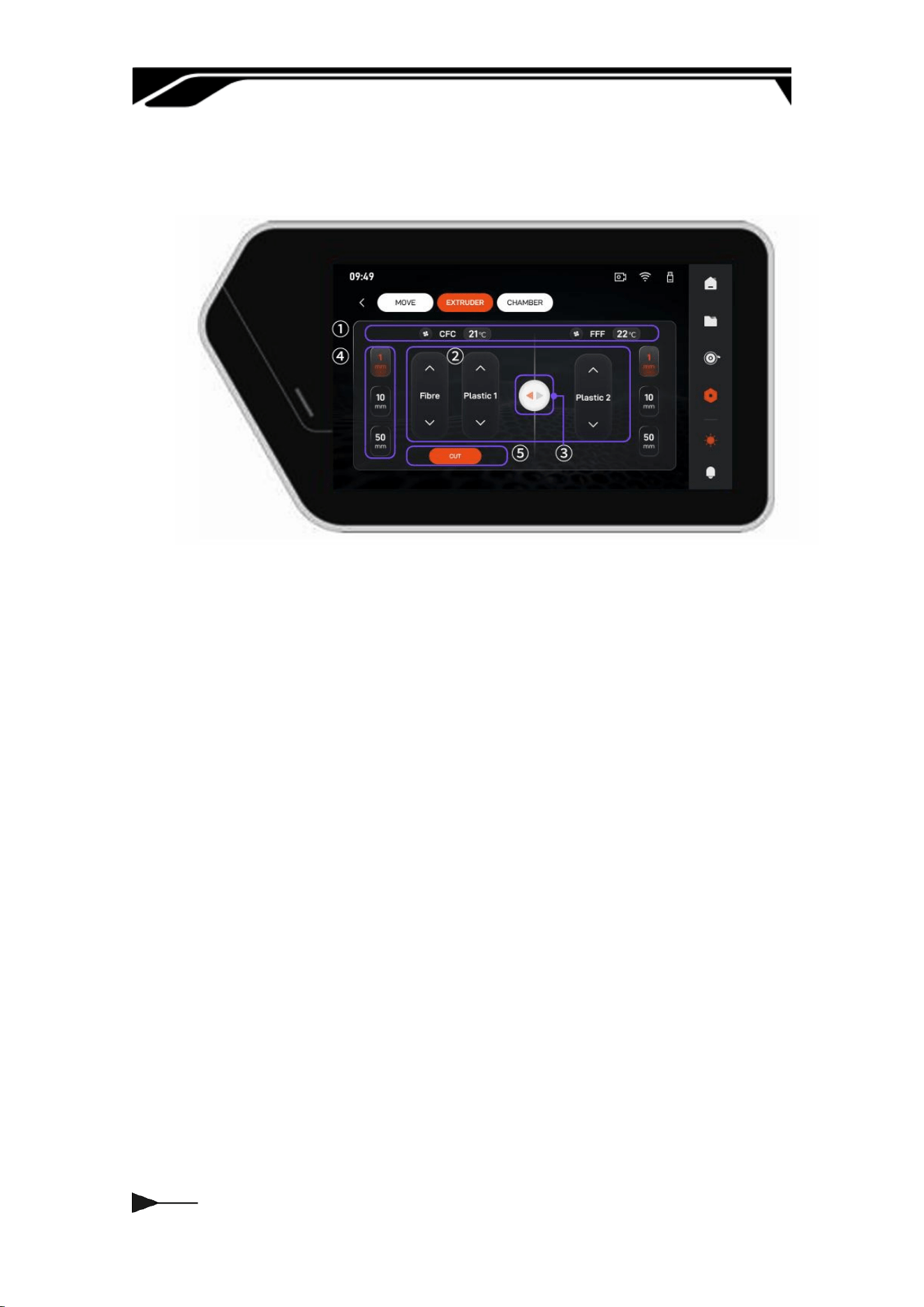
This inteace is the dedicated extruder control panel, integrating dual-nozzle
temperature monitoring, precise material displacement, and ber cutting.
① Temperature Monitoring & Setting
② Extrusion Control
③ Printhead Switching
④ Extrusion Length Selection Area
⑤ Fiber Cutting Control
017
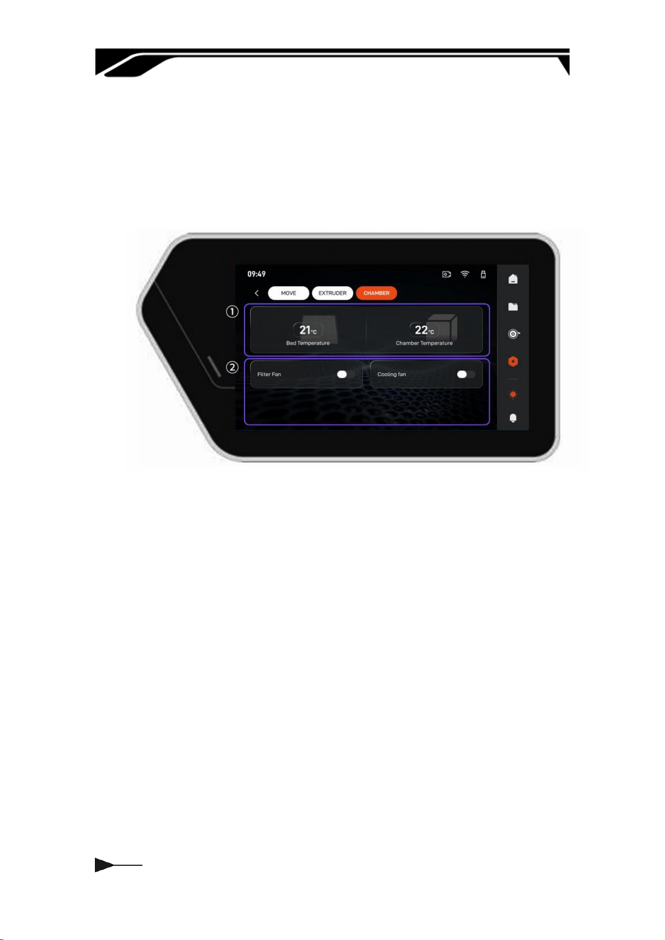
This inteace is the dedicated build environment control panel, focusing on
chamber temperature management and multi-dimensional fan system
regulation. By monitoring chamber and heat-bed temperatures while adjusting
ltration, cooling, and auxilia fans, it maintains a stable and clean
environment to ensure consistent print quality.
① Environmental temperature monitoring
② Function fan switch
018
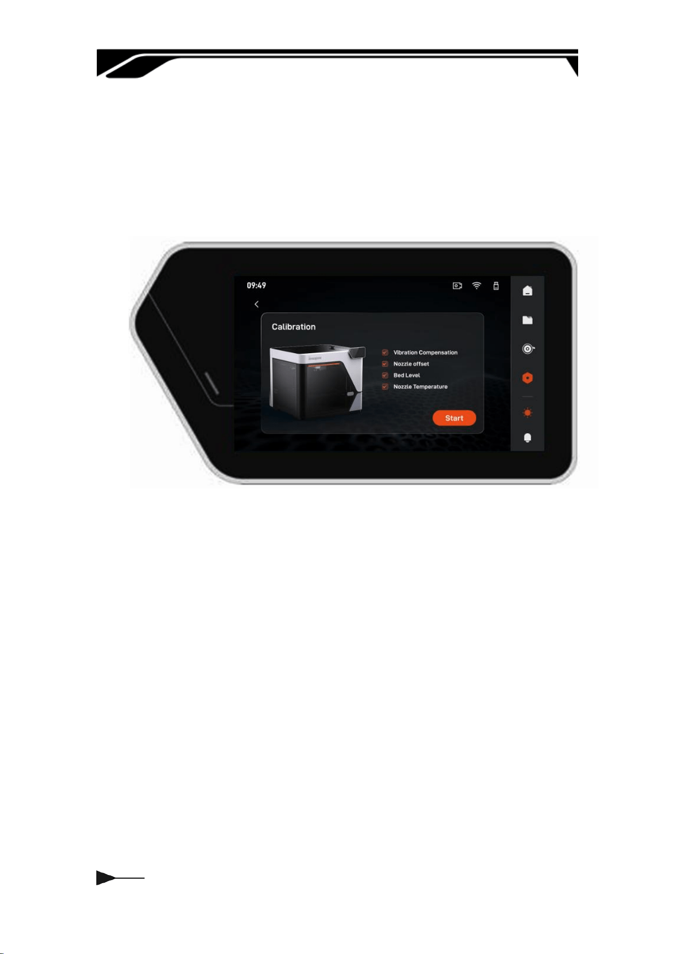
3.2.2 Calibration--Print Calibration
This calibration kit includes self-adjusting functions for vibration compensation,
nozzle oset, heated bed levelling, and nozzle temperature calibration, which
can eliminate deviations and ensure high-quality continuous bre 3D printing.
1. Vibration Compensation: Suppresses resonance to reduce suace
aifacts and improve stability.
2. Nozzle Oset: Corrects dual-nozzle positions to prevent layer
misalignment in multi-material prints.
3. Bed Level: Ensures a uniform nozzle gap to prevent warping or poor
adhesion.
4. Nozzle Temperature: Optimizes heating response for stable temperature
control and precision
019
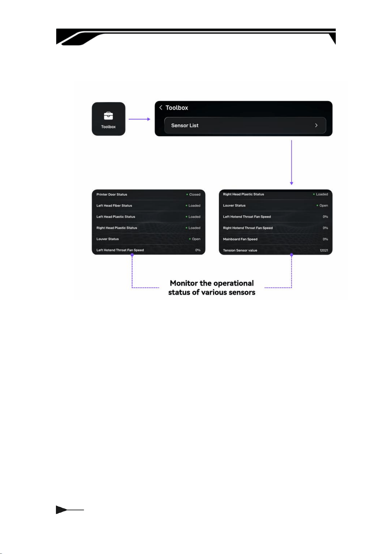
3.2.3 Toolbox
020
3.2.4 Others
021
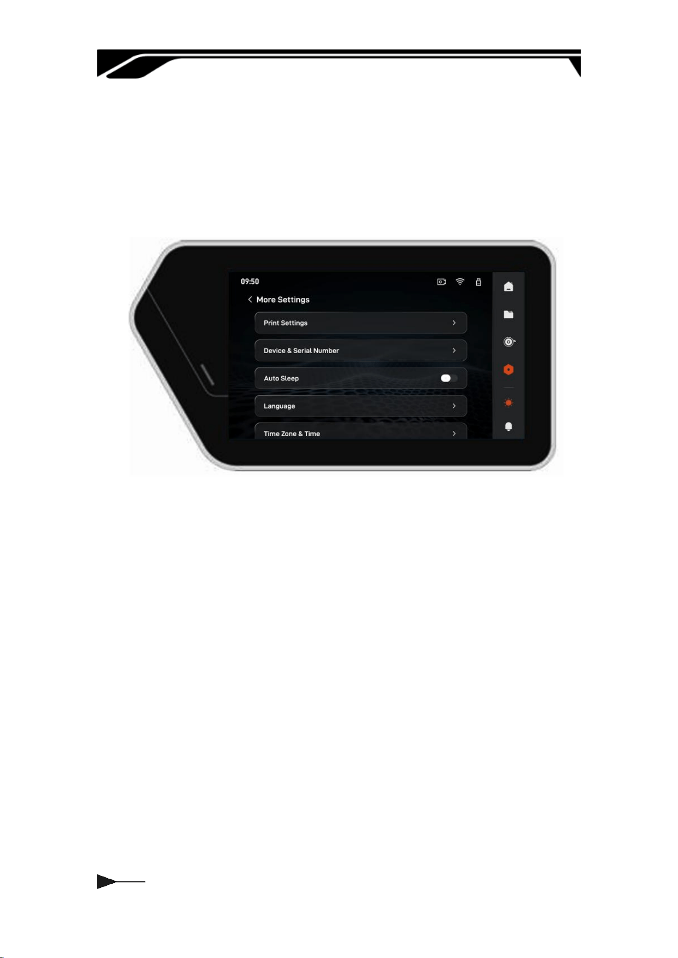
3.2.4 More Settings
It suppos extensive system settings and personalized conguration
operations. You can freely switch the system display language and adjust the
local date and time formats according to your region and usage habits.
022
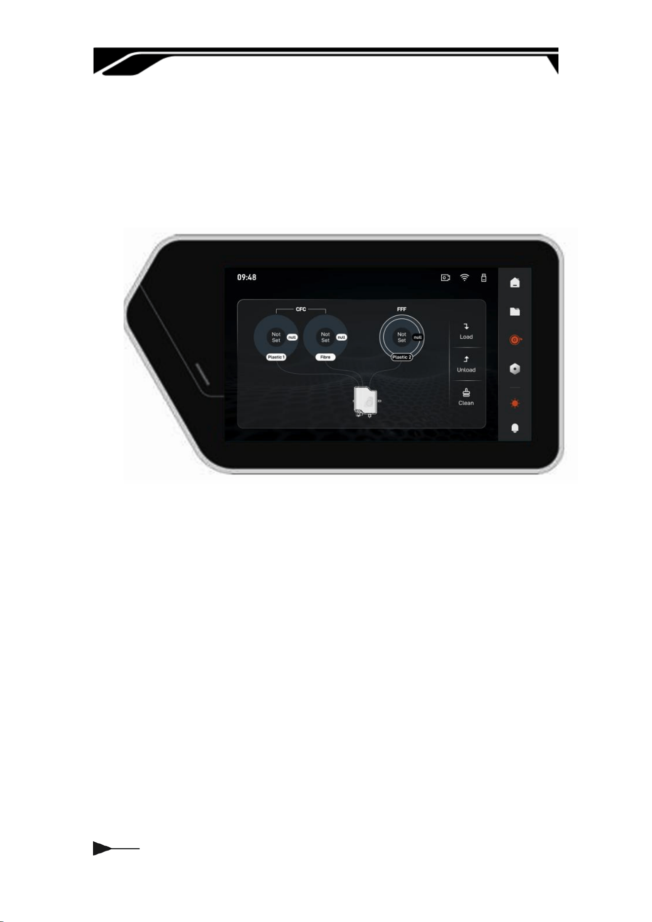
3.3 Materials
When peorming Load or Unload operations, select the corresponding CFC or
FFF materials. The recommended loading sequence is: Composite Plastic →
Fiber → Plastic. Verify material types before loading to ensure a smooth and
stable process.
We recommend using ocial laments to ensure printing stability and quality.
For third-pay materials, please adjust printing parameters according to their
propeies and refer to our lament usage and parameter settings guide.
023
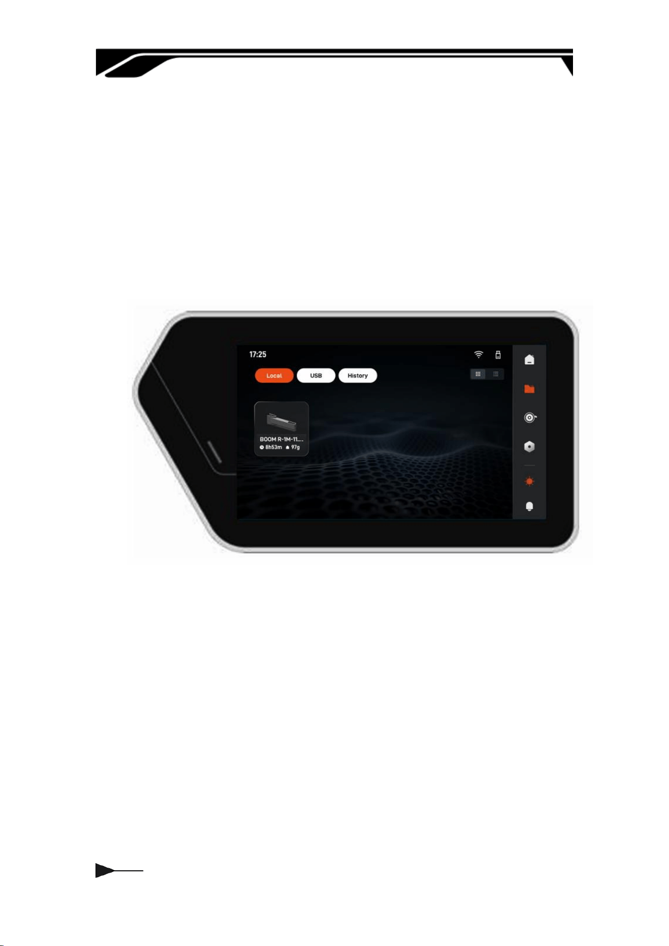
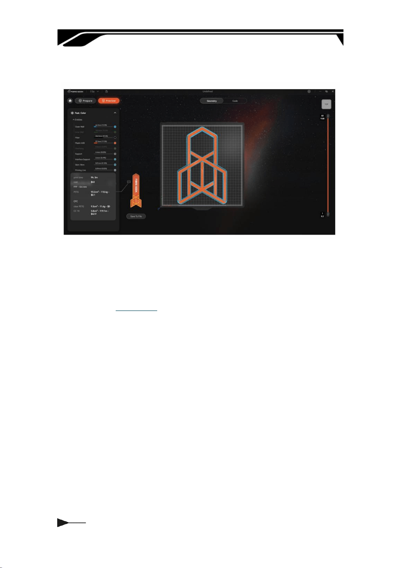
3.4 Printing File
1. Local: Print les stored in local storage, suppoing oine access and
printing to ensure production continuity without network connectivity.
2. USB: Reads and displays les from connected USB devices for quick impo
and cross-device data transfer.
3. Histo: Logs completed or interrupted print tasks, including parameters,
duration, and results, for data tracking and task reprints
The following information is displayed once a le is selected.
1. Basic Process Information: Displays the material type, layer height, model
height, estimated print time, model weight, and print mode, helping users
quickly verify printing processes and material requirements.
2. Auxilia Function Status: Synchronously displays the status of auto
calibration, AI assistance, and time-lapse photography, allowing users to
verify congurations before printing to ensure process control and data
retention.
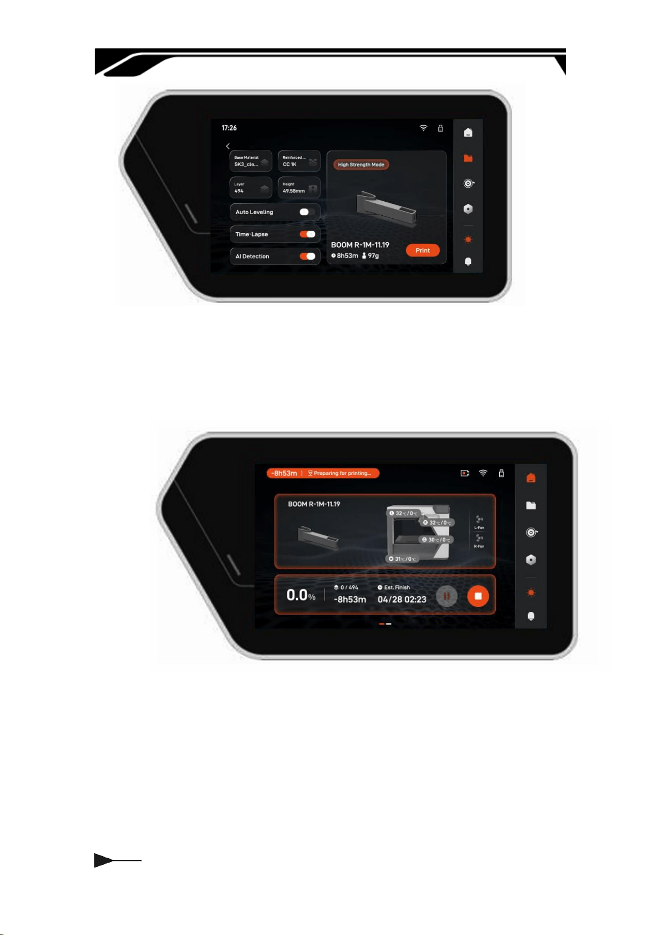
024
The following information is displayed during the printing process. During
the printing process, users can pause or stop the print job. The printing
status can also be monitored remotely.
025
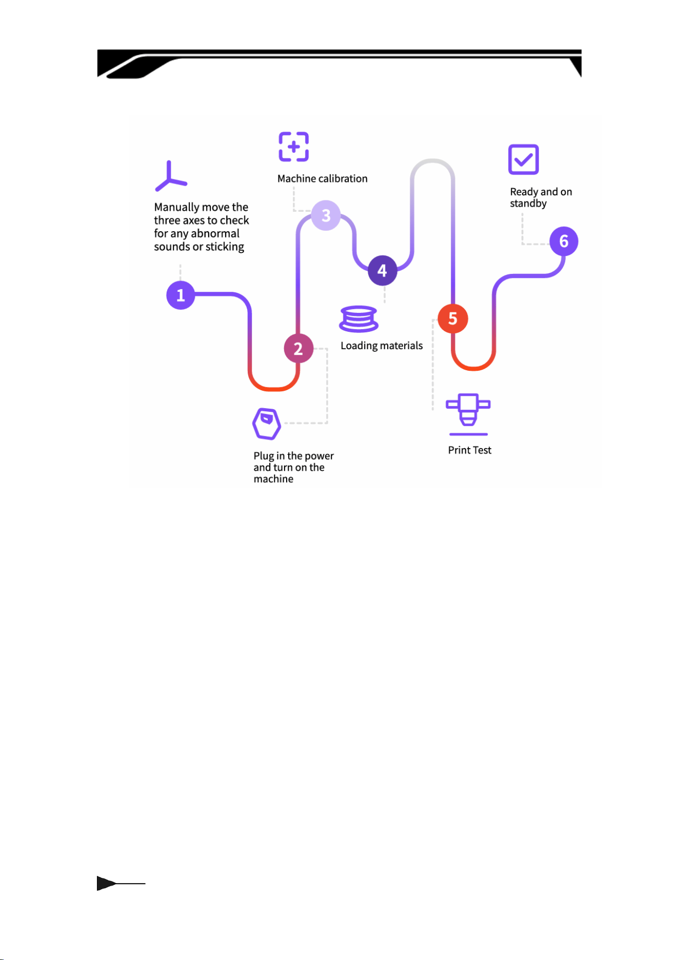
3.5 Workow

026
Chapter Four ADDITIONAL NOTES
4.1 Attention
Power o after cooling
After printing is completed, wait for
the nozzle, heatbed, and chamber to
cool down to a safe temperature
before powering o to avoid
residual heat damaging the
components.
Regular Cleaning and
Maintenance
Regularly clean the dust and
residual material from the nozzle,
lament path, print bed, and inside
the chamber to keep the equipment
clean.
Long-term Storage
When not in use for a long period,
please remove the materials and
store them in a sealed container, and
turn o the main power supply of
the equipment to prevent aging.
Material Usage
To ensure good print quality, highly
hygroscopic materials (such as
PETG, PC, PACF, etc.) should be
dried in a ding chamber before
each print, and it is strongly
recommended to keep them in a
sealed box to maintain dness
during printing.
028
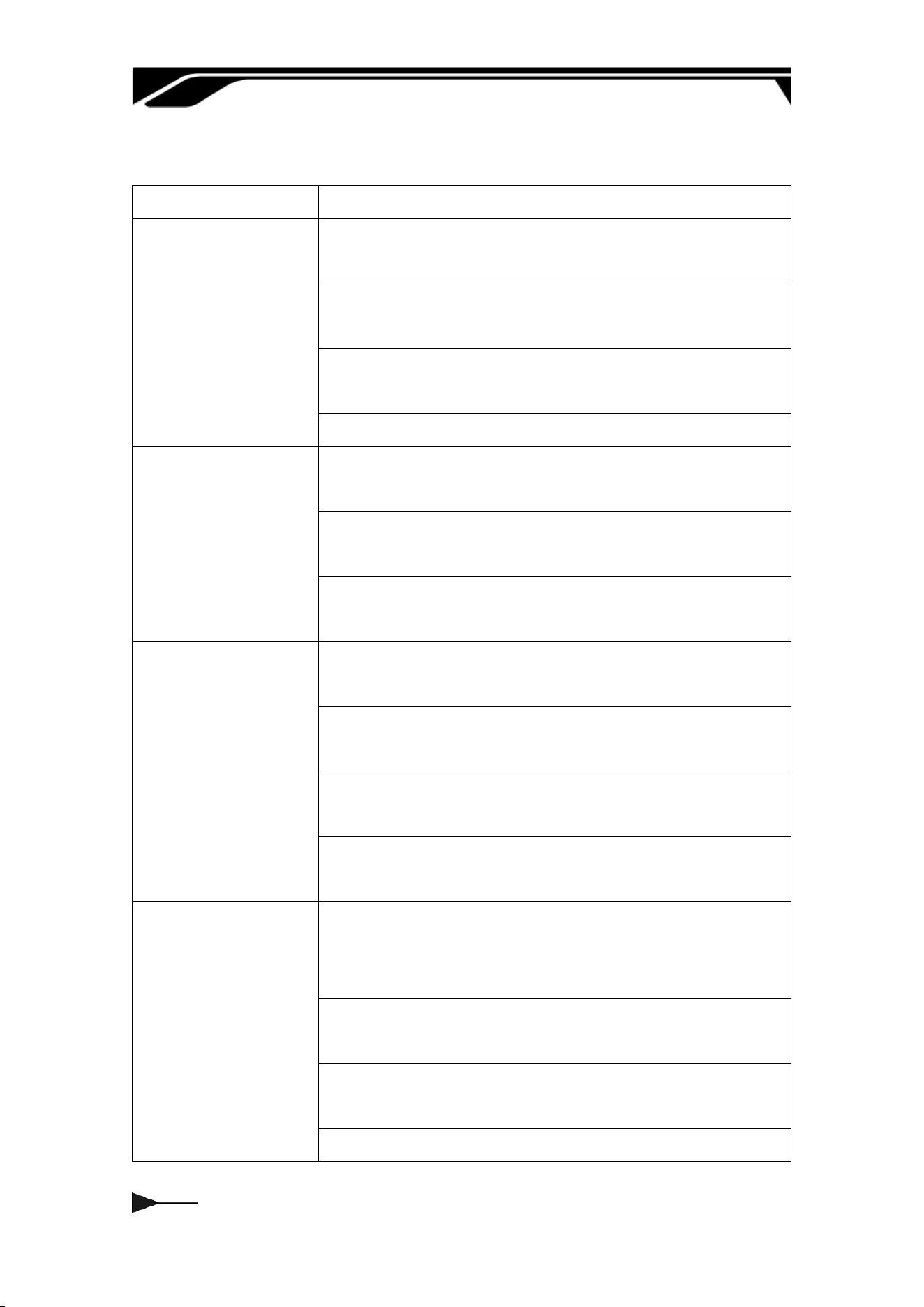
4.3 Maintenance
Frequency
Content
Eve Use
After printing, wipe o residual waste and stringing on
the build plate.
Once the nozzle cools below 50°C, wipe away
carbonized residue on the suace.
Seal and store remaining lament to ensure moisture
protection.
Clean debris from the chamber and close the door.
50hrs
Apply printer-specic grease to guide rails and lead
screws to ensure even lubrication.
Re-verify heatbed leveling and correct deviations to
ensure rst-layer print quality.
Check the power cord and ensure the plug is
connected securely
300hrs
Replace aged, scratched, or clogged PTFE guide
tubes; check connector aiightness.
Inspect nozzle wear; replace directly if uneven
extrusion or frequent clogging occurs.
Re-execute nozzle and heatbed PID calibration to
ensure temperature stability.
Redo vibration compensation calibration to reduce
layer lines and improve precision.
600hrs
Check the synchronous belts and pulleys: replace
them immediately if tooth wear, cracks, or elastic
failure is obseed.
Inspect timing belts and pulleys; replace immediately
if there is tooth wear, cracks, or loss of elasticity
Peorm a full-process calibration: Nozzle Oset + Bed
Leveling + Vibration Compensation + PID Calibration.
Tighten the heater block, thermocouple, and
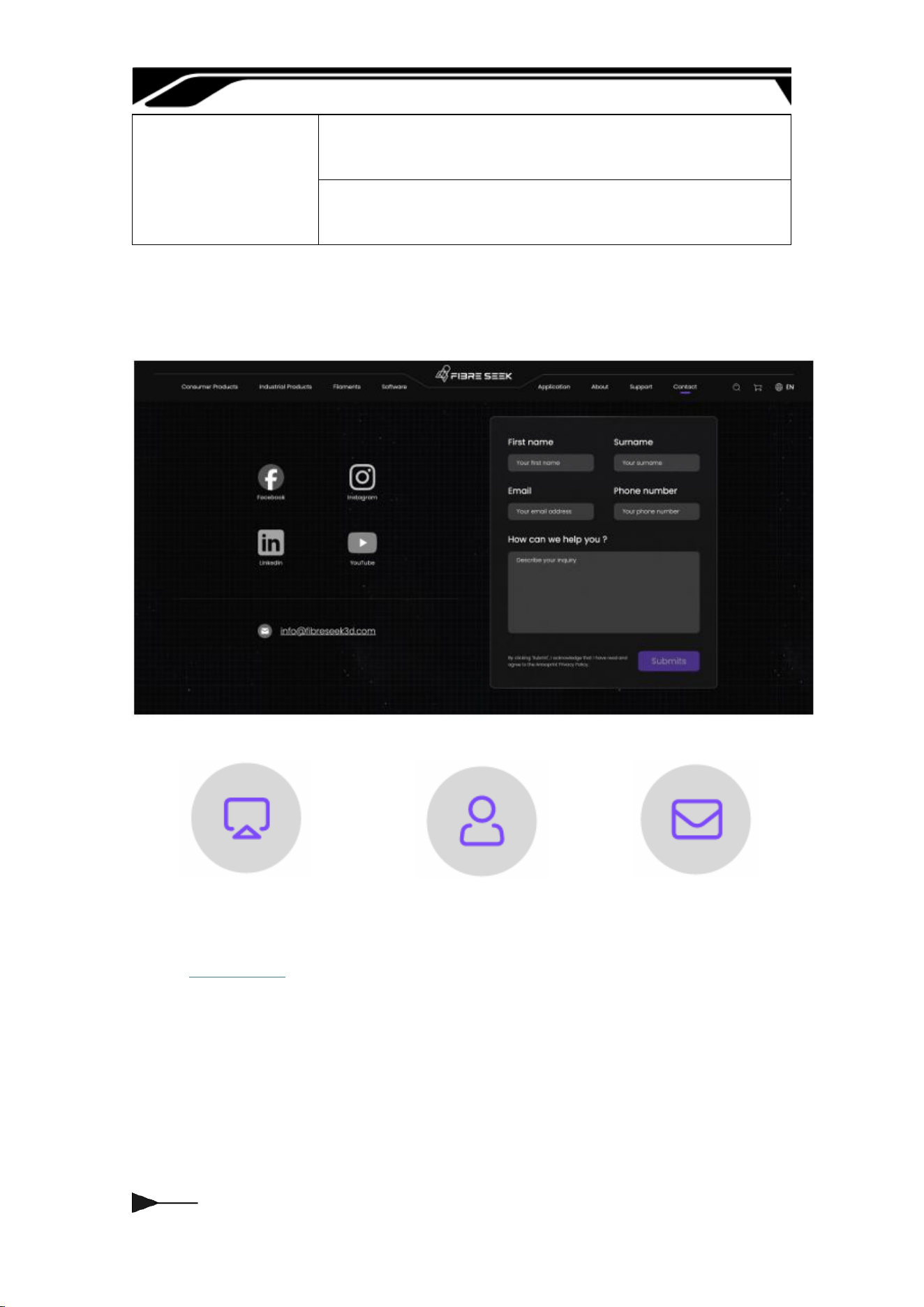

Thank you for your choice! May eve
print be smooth and successful, and may
eve one of your creative ideas take
shape peectly.

FCC Statement
This device complies with part 15 of the FCC Rules. Operation is subject to the following two
conditions: (1) This device may not cause harmful interference, and (2) this device must
accept any interference received, including interference that may cause undesired operation.
This equipment has been tested and found to comply with the limits for a Class B digital
device, pursuant to Part 15 of the FCC Rules. These limits are designed to provide
reasonable
protection against harmful interference in a residential installation. This equipment generates
uses and can radiate radio frequency energy and, if not installed and used in accordance
with the instructions, may cause harmful interference to radio communications. However,
there is no guarantee that interference will not occur in a particular installation. If this
equipment does cause harmful interference to radio or television reception, which can be
determined by turning the equipment off and on, the user is encouraged to try to correct the
interference by one or more of the following measures:
-- Reorient or relocate the receiving antenna.
-- Increase the separation between the equipment and receiver.
-- Connect the equipment into an outlet on a circuit different from that to which the receiver is
connected.
-- Consult the dealer or an experienced radio/TV technician for help.
Any Changes or modifications not expressly approved by the party responsible for
compliance could void the user's authority to operate the equipment.
This equipment should be installed and operated with a minimum distance of 20cm between
the radiator and your body.
This equipment complies with the FCC radiation exposure limits set forth for an uncontrolled
environment, This transmitter must not be co-located or operating in conjunction with any
other antenna or transmitter.