support@accumems.com
T T Series
Pocket Thermal Imager
User Manual
Scan to Get the Latest UM


i
© Hangzhou Accumems Technology Co., Ltd. All rights reserved.
Manual Usage Guidelines
This manual contains functional descriptions and product
usage/management guidelines for various imager models. Due to
functional differences among models within the same series, the
manual may include explanations that are not applicable to your
specific model. All pictures, charts, and other information provided
herein are for descriptive and explanatory purposes only and are
subject to change without notice due to firmware updates or other
reasons. Please note that information regarding new features in the
latest firmware may not be included in a timely manner. Use this
manual under the guidance and assistance of professionals trained in
supporting the product.
For more information or technical support, please visit our official
website
www.accumems.com or send an email to
support@accumems.com.
Trademarks Acknowledgement
and other AccuMEMS’s trademarks and logos are the
properties of Hangzhou Accumems Technology Co., Ltd. in various
jurisdictions. Other trademarks and logos mentioned are the
properties of their respective owners.

ii
CONTENTS
1. Safety Instruction .........................................................................................1
Power Supply ..................................................................................................... 1
Battery ..................................................................................................................... 1
Using Environment ....................................................................................... 2
Transportation ................................................................................................. 3
Maintenance ...................................................................................................... 3
Emergency .......................................................................................................... 3
White Supplement Light .........................................................................4
Laws and Regulations ...............................................................................4
Recycling ..............................................................................................................4
2. Product Appearance.............................................................................. 5
3. Getting Started ............................................................................................. 7
Charging for the Imager ......................................................................... 7
Power On/Off the Imager .................................................................... 7
Menus and Controls ..................................................................................8
4. Usage Scene Configuration ........................................................... 11
Choose a Usage Scene .......................................................................... 11
(Optional) Configure Usage Scene Parameters .............. 15

iii
5. Temperature Measurement............................................................17
Measurement Tools Configuration ............................................... 17
Temperature Accuracy Parameters Configuration ....... 18
Alarm Configuration .............................................................................. 20
6. Display Configuration ......................................................................... 21
Brightness Configuration...................................................................... 21
Auto-Rotation Configuration ............................................................ 21
UIRA-IR Configuration ............................................................................ 21
Image Mode Configuration .............................................................. 22
Level & Span Configuration ............................................................ 22
Digital Zoom Configuration .............................................................. 23
On-Screen Info Configuration ........................................................24
7. Pictures and Videos ............................................................................ 25
Capture Pictures ......................................................................................... 25
Record Videos ............................................................................................. 27
View Pictures and Videos ................................................................. 27
Manage Files .................................................................................................28
Manage Albums ......................................................................................... 30
Export Files ..................................................................................................... 31

iv
8. Device Connection ................................................................................ 32
Connect via Hotspot (If Applicable) .......................................... 32
9. Maintenance ................................................................................................. 33
Time and Date Configuration .......................................................... 33
Unit Configuration .................................................................................... 33
View Imager Information .................................................................... 33
Format Memory .......................................................................................... 33
Logs Configuration ..................................................................................34
Upgrade ............................................................................................................34
Restore Imager Configuration .......................................................34
10. Guidance for Common Thermal Imaging
Operations ........................................................................................................... 35
Can the UIRA-Scene Algorithm Detect Water Leaks,
Insulation Issues or Heat Irregularities with 100%
Accuracy? ................................................................................................................. 35
Factors may Interfere with the Detection Results of
UIRA-Scene .............................................................................................................. 35
Improve Water Leak Detection Success Rates ............36
Higher-Quality Image ..........................................................................36
Guidance on Using Thermal Imaging for Common
Water Leak Detection.................................................................................... 37

v
Detect Water Pipe Leaks ................................................................38
Can the Thermal Imager Penetrate Walls or Floors?41
Check a Thermal Imager’s Temperature Accuracy ... 41
Frozen Images ............................................................................................ 41
Prolong Battery Life ...........................................................................42


1
1. Safety Instruction
Read all the safety notes and instructions in the AccuMEMS User
Manual for use of the AccuMEMS products. Failure to heed the
following instructions can lead to electric shock, fire and/or severe
injuries.
Power Supply
Voltage Compliance: Input voltage must comply with IEC62368
Limited Power Source specifications (3.85 VDC, 570 mA). Refer to
technical specifications for full requirements.
Manufacturer Standards: Use only adapters from qualified
manufacturers. Refer to the product specification for detailed power
requirements.
Connection Requirements: Securely insert plug into power socket
until fully engaged.
DO NOT connect multiple imagers to one power adapter, to avoid
over-heating or fire hazards caused by overload.
Battery
Warning: Explosion Hazard
Confirm there is no flammable material within 2 m of the charger
during charging.
Prohibited Disposal Methods
-
DO NOT dispose in fire or high-temperature ovens.
-
DO NOT mechanically crush or cut the battery.
-
DO NOT expose the battery in an extremely high temperature
environment, which may result in an explosion or the leakage of
flammable liquid or gas.

2
-
DO NOT subject the battery to extremely low air pressure, which
may result in an explosion or the leakage of flammable liquid or gas.
-
DO NOT place the battery near heating or fire source. Avoid direct
sunlight.
-
DO NOT swallow the battery to avoid chemical burns.
-
DO NOT place the battery in the reach of children.
Mandatory Disposal: Follow battery manufacturer's recycling
instructions precisely.
Integrated Battery Maintenance
-
The built-in battery cannot be dismantled. Please contact the
manufacture for repair if necessary.
-
For long-term storage: Maintain full charge every 90 days.
Otherwise, damage may occur.
-
Before using the imager after storage, turn off the imager and
charge it for at least 30 minutes.
Using Environment
Running Environment Requirement of the Imager:
-
The operating temperature shall be -10 °C to 50 °C (14 °F to
122 °F), and the operating humidity shall be 95% or less.
-
Place the imager in a dry and well-ventilated environment.
-
The level of protection is IP 54.
Prohibitions:
-
DO NOT expose the imager to high electromagnetic radiation or
dusty environments.
-
DO NOT aim the lens at the sun or any other bright light.
-
The imager is suitable for indoor use only.

3
Transportation
Packaging Requirements: Transport the imager exclusively in its
original packaging or equivalent protective materials. Retain all
packaging components after unboxing for potential reuse
Return & Liability Conditions: In the event of imager failure requiring
factory return: utilize original packaging or equivalent packaging for
transportation. Transportation without original packaging may cause
damage, and the manufacturer assumes no liability for damages
occurring under such circumstances.
Operational Prohibitions: DO NOT drop the product or subject it to
physical shock. Keep the imager away from magnetic interference.
Maintenance
DO NOT maintain the imager when it is powered on, or it may cause
electric shock!
If the product does not work properly, please contact your dealer or
the nearest service center. We shall not assume any responsibility for
problems caused by unauthorized repair or maintenance.
Wipe the imager gently with a clean cloth and a small quantity of
ethanol, if necessary.
If the equipment is used in a manner not specified by the
manufacturer, the protection provided by the device may be
impaired.
Emergency
Upon detecting smoke, abnormal odors, or noise originating from the
imager:
immediately cut all power sources
unplug the power cable
notify authorized service center

4
White Supplement Light
The light beam at 200 mm distance is classified as Risk Group 1
(RG1).
Use proper eye protection or keep the white light off during imager
assembly, installation, or maintenance.
Without adequate shielding or eye protection, activate the light only
at a safe distance (1.3 m) or in areas not directly exposed to the beam
during setup or servicing.
Laws and Regulations
Use of the product must be in strict compliance with the local electrical
safety regulations.
Recycling
Please follow local recycling requirements for proper disposal.
5
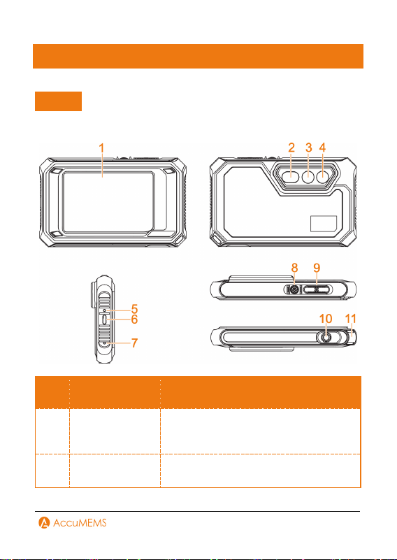
2. Product Appearance
NOTE
Imager models may differ in appearance and componentry. Always
refer to your imager.
No. Component Function
1 Touch Screen
View images and operate the imager via
touch control.
2 Flashlight
Provides fill light for objects.
Emits a flashing alarm signal.

6
3 Thermal Lens View the thermal image.
4 Visual Lens View the visual image.
5 Buzzer Emit sound alarm.
6
Indicator of the
Charger
Solid Red: Charging in progress.
Solid Green: Fully charged.
7
Type-C
Interface
Battery charging and data export.
8 Microphone
Records audio.
9 Power Button
Hold: Turn the imager on/off.
10 Capture Button
In Real-time Interface:
Press: Capture a snapshot.
Hold: Start recording a video; press
again to stop.
In Menu Interface:
Press: Back to real-time interface.
11 Tripod Mount Mount the imager on a tripod.
12 Strap Mount Attach a wrist strap here.

7
3. Getting Started
Charging for the Imager
User should prepare a power adapter to charge the imager. The
adapter (not included) should meet the following requirements:
Output Voltage/Current: 5 VDC/2 A
Minimum Power Output: 10 W
1.
Open the Type-C interface protective cover.
2.
Insert the included USB cable into the port, and connect the imager
to a power source via the power adapter for charging.
NOTE
The power delivered by the charger must be between min 8 Watts
required by the radio equipment, and max 10 Watts in order to
achieve the maximum charging speed.
It is advised to use the USB cable that came with your imager for
charging and file transfers.
It is advised to charge the imager for at least half an hour before
turning it on if it has been over-discharged from prolonged
inactivity.
Power On/Off the Imager
Power On
To activate the imager, hold for more than 3 seconds. When the
imager's interface is steady, you can see the target.
NOTE
After turning the imager on, it can take at least 6 seconds before it is
ready for use.
8
Power Off
When powered on, hold for more than 3 seconds to turn off the
imager.
Auto Power-Off Configuration
To configure the imager’s automatic shutdown time as needed, go to
More Config
Auto Power-off.
Menus and Controls
The imager features a touch-control screen, allowing for all controls
via simple screen taps.
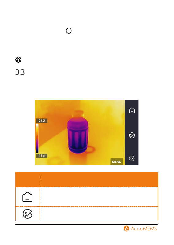
Real-Time Menu
Icon Description
Tap to exit the current interface and return to the real-
time interface.
Access captured images and videos.
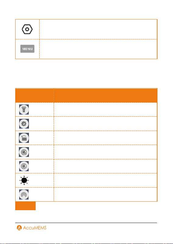
9
Configure local imager preferences and basic
operations.
Configure measurement tools, image modes, palettes,
and level & span.
Swipe-down Menu
On the real-time interface, swipe down from the top to open the swipe-
down menu. You can turn imager functions on or off, switch display
themes, and adjust screen brightness etc.
Icon Description
Turn the flashlight on or off.
Switch between day and night themes.
Adjust the screen orientation.
Enable or disable the imager's auto-calibration.
Manually initiate a calibration for the imager.
Adjust the screen brightness.
Turn on/off hotspot.
NOTE

10
By connecting the imager to the APP via hotspot, users can view
the real-time interface, capture snapshots, record videos, and
transfer files.
As this manual is updated regularly, the interfaces may differ
slightly from your specific model. Always refer to your imager.

11
4. Usage Scene Configuration
To facilitate rapid anomaly detection, Usage Scene offers a range of
preset templates designed for different situations.
1.
Choose a suitable scene or create a customized one according to
detection targets. Refer to 4.1 Choose a Usage Scene for detailed
instructions.
2.
Configure measurement tools to monitor real-time temperatures at
the highest, lowest, or center points. Refer to 5.1 Measurement
Tools Configuration for detailed instructions.
3.
(Optional) Adjust scene parameters. Refer to 4.2 (Optional)
Configure Usage Scene Parameters for detailed instructions.
4.
(Optional) Configure alarms as needed. Refer to 5.3 Alarm
Configuration for detailed instructions.
5.
See detection results in the real-time interface.
Choose a Usage Scene
In real-time interface, go to
Usage Scene to choose a desired
scene.
Moisture Detect
This scene is used to detect water leaks on indoor building ceilings,
walls, and floors.
UIRA-Scene technology enables rapid identification of irregularities
during leak inspections. Upon enabling this function, if moisture
irregularities are detected, the system will mark them with “Suspect”
indicators and red frames in the real-time interface.
NOTE
If the temperature difference in areas with moisture irregularities
is too subtle to be detected, missed or incorrect reporting may
occur.

12
A secondary diagnosis using the UIRA-Scene function is
recommended. The algorithm for this function is currently being
updated.
Simultaneously enabling UIRA-IR and UIRA-Scene reduces the
frame rate.
To use the alarm function of this scene, go to
Alarm Trigger.
For details, refer to 5.3 Alarm Configuration.
The picture is for reference only. Always refer to your imager.
Home Insulation
This scene is used to detect home insulation irregularities of indoor
building structures such as walls and ceilings, common users can apply
this scene.
UIRA-Scene technology enables rapid identification of irregularities
during insulation inspections. Upon enabling this function, if insulation
irregularities are detected, the system will mark them with “Suspect”
indicators and red frames in the real-time interface. If air leak points
are detected, the system will mark them with “Suspect Air Leak”
indicators and red frames in the real-time interface.
NOTE
If the temperature difference in areas with insulation irregularities
is too subtle to be detected, missed or incorrect reporting may
occur.
A secondary diagnosis using the UIRA-Scene function is
recommended. The algorithm for this function is currently being
updated.
Simultaneously enabling UIRA-IR and UIRA-Scene reduces the
frame rate.
To use the alarm function of this scene, go to
Alarm Trigger.
For details, refer to 5.3 Alarm Configuration.
The picture is for reference only. Always refer to your imager.

13
Pro Insulation
This scene is used to detect indoor insulation anomalies of building
walls and ceilings. The required parameters include Indoor Temp.,
Outdoor Temp., and Insulation Level.
When indoor temperature is less than or equal to outdoor
temperature, regions with insulation levels surpassing the preset
threshold will be highlighted in cyan. Conversely, if indoor temperature
exceeds outdoor temperature, areas with insulation levels lower than
the preset threshold will be marked in cyan.
NOTE
Relative Humidity represents the current humidity level.
Ambient Temperature represents to the current atmospheric
temperature.
RH Threshold represents the humidity upper limit of the target
surface. A relative humidity of 100% signifies that water vapor
condenses into liquid water (dew point), while levels around 70%
or higher may promote mold growth.
Values of Relative Humidity and Ambient Temp. can be acquired
using hygrometers and thermometers respectively.
Pro Moisture
To detect potential indoor moisture issues, it is necessary to configure
Relative Humidity, Ambient Temp., and RH Threshold.
Regions with condensation issues will be highlighted in green when the
measured relative humidity surpasses the specified RH Threshold.
NOTE
Relative Humidity represents the current humidity level.
Ambient Temperature represents to the current atmospheric
temperature.
RH Threshold represents the humidity upper limit of the target
surface. A relative humidity of 100% signifies that water vapor

14
condenses into liquid water (dew point), while levels around 70%
or higher may promote mold growth.
Values of Relative Humidity and Ambient Temp. can be acquired
using hygrometers and thermometers respectively.
Floor Heating
This scene is used to detect and monitoring faults in underfloor heating
systems.
UIRA-Scene technology enables rapid identification of irregularities
during floor heating inspections. Upon enabling this function, if heat
irregularities are detected, the system will mark them with “Suspect”
indicators and red frames in the real-time interface.
NOTE
If the temperature difference in areas with heat irregularities is
too subtle to be detected, missed or incorrect reporting may occur.
A secondary diagnosis using the UIRA-Scene function is
recommended. The algorithm for this function is currently being
updated.
Simultaneously enabling UIRA-IR and UIRA-Scene reduces the
frame rate.
To use the alarm function of this scene, go to
Alarm Trigger.
For details, refer to 5.3 Alarm Configuration.
The picture is for reference only. Always refer to your imager.
Electrical Failure
Used for detecting and monitoring faults in wires, circuits, electrical
components, terminators, and similar items.
Solar Panel
Used for detecting and monitoring faults in solar panels.
Custom
Allows users to create a personalized mode by saving preferred

15
temperature measurement parameters for later use. Refer to 4.2
(Optional) Configure Usage Scene Parameters for detailed
instructions.
(Optional) Configure Usage Scene
Parameters
Users can adjust related parameters in
Usage Scene to achieve
more precise detection results.
NOTE
Parameters vary depending on the selected usage scene.
Parameters Description
Distance
Configure the distance between the
imager and the target object.
Emissivity
Configure the emissivity value
according to the target object.
Palettes
Palettes represent temperature using
different colors. Users can select a
preferred color palette.
Level & Span
The temperature scale on the left helps
visualize the color-temperature
relationship in the image. Refer to
6.5
Level & Span
for detailed
instructions.
Temperature Range
Select the temperature measurement
range. In Auto Switch mode, the imager

16
automatically detects temperature and
switches ranges accordingly.
Alarm Config
When the target temperature triggers
a configured alarm rule, users can be
notified through configured rules.
Refer to 5.3 Alarm Configuration
for
detailed instructions.
Color Display
Choose between Histogram and
Linear modes for different scenarios to
enhance detail visibility:
Histogram: Enhances visibility of
small low-temperature targets in
high-temperature areas.
Linear: Optimized for detecting small
high-temperature targets against a
low-temperature background.

17
5. Temperature Measurement
To get more precise and real-time temperature of the target, user can
set spot tools and alarms as needed.
1.
For imagers with Usage Scene, choose an appropriate scene to
streamline measurement configurations. Refer to 4 Usage Scene
Configuration for detailed instructions.
2.
Configure measurement tools to monitor real-time temperatures at
the highest, lowest, or center points. Refer to 5.1 Measurement
Tools Configuration for detailed instructions.
3.
Check temperature values displayed in the real-time interface's top-
left corner. Configure temperature measurement parameters if
accuracy is insufficient. Refer to 5.2Temperature Accuracy
Parameters Configuration for detailed instructions.
4.
(Optional) Enable alarms. Refer to 5.3 Alarm Configuration for
detailed instructions.
5.
Review temperature results directly in the real-time interface.
Measurement Tools Configuration
The imager measures the entire scene temperature and can be
configured to display center, hot, and cold points.
Set Measurement Tools
1.
In real-time interface, go to
.
2.
Tap to select temperature measurement tools as required. Hot,
Cold, and Center are selectable.
Max: Display the scene's hot point and its max. temperature.
Min: Display the scene's cold point and the min. temperature.
Cen: Display the scene's center point along with the temperature.
3.
Tap any place on screen to save and exit.

18
NOTE
The imager will display the real-time temperature on the upper left
corner of real-time interface.
Reset Measurement Tools
To clear all measurement tools, go to
More Config
Device
Initialization
Remove All Measurement Tools.
A confirmation message "Setting Succeeded" will appear.
NOTE
The palette is also restored to the default settings.
Temperature Accuracy Parameters
Configuration
To increase temperature measurement accuracy, you can adjust the
measurement parameters.
NOTE
After adjusting the emissivity and distance parameters in the Temp.
Settings , the emissivity and distance values in the Usage Scene will
also be modified accordingly.
Emissivity:
Configure the target's emissivity. Emissivity is a parameter that
measures the thermal radiation capability of an object's surface,
indicating the efficiency with which the object emits energy outward.
1.
In real-time interface, go to
Temp. Settings.
2.
Choose a preset value or customize it.
3.
Tap to save and exit.
Distance:
Configure the distance between the target and the imager.
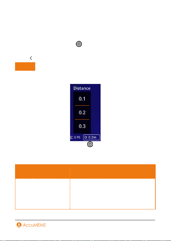
19
For templates based on approximate camera-to-target distance, use
Near/Middle/Far modes.
For precise customization, choose Custom mode.
1.
In real-time interface, go to
Temp. Settings
Distance.
2.
Choose a distance mode.
3.
Tap to save and exit.
NOTE
In real-time interface, scroll the distance wheel to quickly adjust the
temperature measurement distance.
In real-time interface, you can go to
Temp. Settings to set other
parameters.
Other Parameters:
Parameters Description
Refl. Temp.
Set the Refl. Temp. to match
interfering high-temperature objects
when measuring low-emissivity targets
to avoid reflection errors.
20
Humidity
Configure the ambient humidity.
Alarm Configuration
Configure the alarm rule and the imager will alarm when the detected
temperature triggers the rule.
NOTE
Before using alarm trigger, please first turn on Alarm in Usage
Scene. Otherwise, alarm trigger will not be visible in the settings
interface.
Only some scenes support the alarm function.
1.
In real-time interface, go to
Usage Scene to select a scene.
2.
In Usage Scene setting interface, tap Alarm Config.
3.
Enable Temperature Alarm button.
4.
Set the alarm rule. Select More Than or Less Than as needed.
5.
Tap Alarm Threshold to set the temperature limits by scrolling the
wheel.
6.
Tap to save and exit.
NOTE
The temperature value displayed in the top-left corner of the real-
time interface changes color based on threshold alerts: red when
exceeding the upper limit, blue when falling below the lower limit.
7.
(Optional) Tap
Alarm Trigger to set flashing/audible alarms.

21
6. Display Configuration
Brightness Configuration
Go to
Display Config
Screen Brightness to adjust the screen
brightness.
Or open the swipe-down menu, tap , and adjust the slider to
change the brightness.
Auto-Rotation Configuration
Go to
Display Settings
Auto-Rotation to turn on this
function.
Or open the swipe-down menu, turn on auto-rotation.
UIRA-IR Configuration
UIRA-IR is an advanced technology, improving object edges for clearer
image quality in both real-time viewing (for some models) and captured
pictures. Actual performance may vary by model.
Real-time View: When UIRA-IR is enabled, supported models
enhance object contours during real-time viewing.
Pictures: UIRA-IR sharpens object outlines in captured images after
activation.
NOTE
UIRA-IR is only supported by certain models. Always refer to your
imager.
UIRA-IR is enabled by default. To disable it, go to
UIRA-IR to
turn it off.

22
Image Mode Configuration
You can configure the imager's thermal/visual display mode. The
selectable options include Thermal, Fusion, PIP, Blending, and Visual
modes.
1.
Go to
.
2.
Tap the icons to select an image mode.
Mode Description
Thermal The imager presents the thermal imaging view.
Fusion
Thermal object The imager shows thermal images with
visual outlines. This function is only supported by
models equipped with a visual lens.s displayed with
visual outlines.
PIP
The imager shows the thermal image within the visual
image.
Blending
The imager merges thermal and visual image. The
balance between thermal and visual elements can be
adjusted.
Visual
Visual image only.
3.
Tap screen to exit.
Level & Span Configuration
Adjust the level & span parameters to get better image contrast.
1.
Choose a suitable palette:
Tap
in real-time interface.
Or go to
Usage Scene
Palettes.
2.
Configure Level & Span:
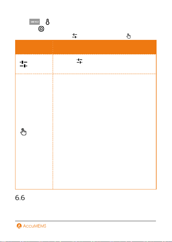
23
Tap
in real-time interface.
Or go to
Usage Scene
Level & Span.
3.
Choose auto adjustment or manual adjustment .
Mode Steps
Auto
Enabling Auto mode can automatically
adjust the display temperature range.
Manual
1.
Tap an area of interest on the screen. A circle
will appear around the area, and the display
temperature range will adjust to show
maximum detail of that area.
2.
Tap the maximum or minimum temperature
scale values to lock or unlock them. Scroll the
wheel to adjust any unlocked values.
3.
Alternatively, unlock both the maximum and
minimum temperatures. Scroll the wheel to
increase or decrease either value individually
while preserving the same temperature range.
4.
Tap Persist Saved or Temp Saved at the
bottom of the screen.
Persist Saved: The current manual mode
settings will be saved and restored after the
imager restarts.
Temp Saved: The settings will not be saved
upon restart, and the imager will revert to
automatic mode.
Digital Zoom Configuration
1.
Tap the real-time interface to display the digital zoom frame.
2.
Tap the frame, then select the digital zoom ratio.

24
3.
Tap the real-time interface to save and exit.
On-Screen Info Configuration
Go to
Display Config to turn on/off the information on-screen
display.
Time and Date: Device time and date.
Parameters: Temperature measurement parameters.
Temperature Scale: Display the palettes bar and temperature range
on the right side of the screen.
25
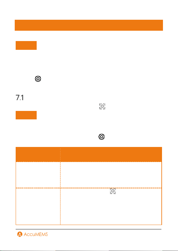
7. Pictures and Videos
NOTE
You cannot capture pictures or recording videos when the menu is
shown.
You cannot capture pictures or recording videos when the imager
is connected with PC.
Go to
More Config
Device Initialization to prepare
storage as needed.
Capture Pictures
In the real-time interface, you can press to capture pictures.
NOTE
If the environment is dark when capturing pictures, you can turn on
the flashlight for illumination.
In the real-time interface, you can go to
Capture Config to set
following parameters.
Parameters Description
Save Visual
Image & Visual
Image Resolution
To save visual images independently, you can
enable Save Visual Image and set Visual
Image Resolution.
Capture Mode
One Picture: Press once to capture
one picture.
Capture Plan: Configure Interval (the time
gap between each picture to be taken) and
Number (the number of pictures to be
captured in sequence, from 1 to 10,000) for
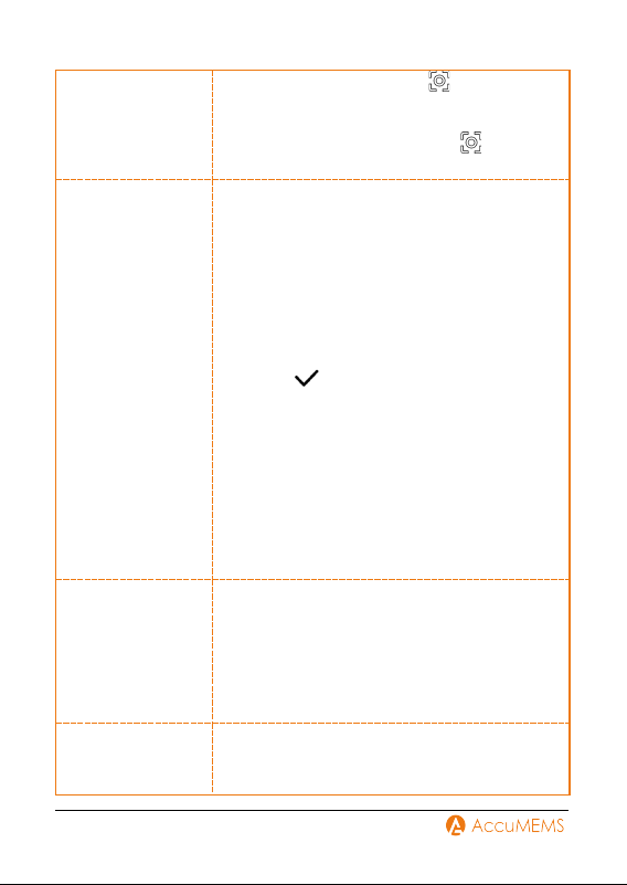
26
scheduled capture. Press in real-time
interface, and the imager captures the
specified number of pictures according to
the configured interval. Press again to
stop capturing.
Edit before
Saving
In capture One Picture mode, enable Edit
before Saving to modify the captured image
immediately.
Text Note:
1.
Choose Text Note to enter the editing
interface.
2.
Tap the screen to add content.
3.
Press to save.
QR Code Note:
1.
Select QR Code Note to switch the imager
to scanning mode.
2.
Align the scanning frame with a QR code.
The imager will automatically read and save
the code's information.
3.
(Optional) If scanning fails, manually enter
the Asset ID using the on-screen keyboard.
Filename Header
Define file naming conventions. Default
naming uses Filename Header + Time Stamp.
Filename header is customizable.
Time stamp reflects the imager’s system
time at capture.
File Naming
Files can be named using Time Stamp or
Numbering.
27
NOTE
One Capture mode freezes the real-time interface and saves to
the default album.
Capture Plan mode shows a counter in the real-time interface
indicating completed captures.
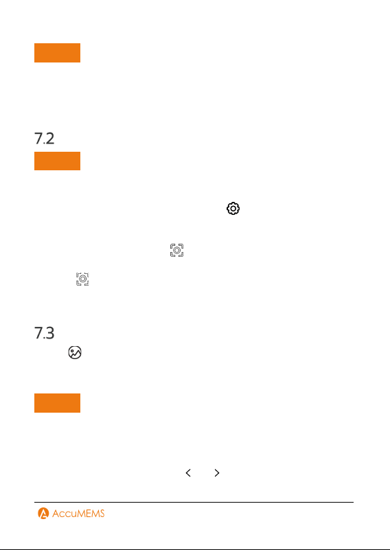
Record Videos
NOTE
If the environment is dark when recording videos, you can turn on
the flashlight for illumination.
1.
(Optional) In real-time interface, go to
Capture
Config
Record Audio to enable or disable audio during video
recording.
2.
In real-time interface, hold to begin recording. When the
recording icon and time display in the interface, recording begins.
3.
Press completes the recording. The imager will display a pop-up
notification saying "Recording Succeeded”. The recording video will
be saved.
View Pictures and Videos
1.
Tap to enter Pictures.
2.
Tap the album, and choose the picture or video.
3.
View the selected file and associated information.
NOTE
Files are organized chronologically, with the newest appearing at the
top. Should you be unable to locate recently captured snapshots or
videos, verify your imager’s time and date settings. Refer to 9.1Time
and Date Configuration for detailed instructions. While viewing files,
switch between files by tapping or .
28
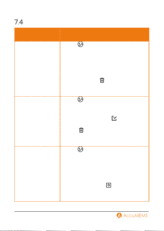
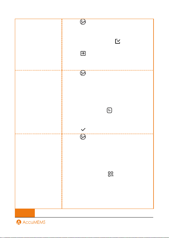
Manage Files
Task Operations
Delete a File
1.
Tap to enter Pictures.
2.
Tap the album that contains the file to be
deleted.
3.
Within the album, tap to view the file to
be deleted.
4.
Tap the screen to show the menu bar
below, then tap . A confirmation
dialog will appear.
5.
Tap OK to delete the file.
Delete Multiple
Files
1.
Tap to enter Pictures.
2.
Tap the album that contains the files to
be deleted.
3.
Within the album, tap , then choose
the files to be deleted.
4.
Tap . A confirmation dialog will
appear.
5.
Tap OK to delete the files.
Move a File
1.
Tap to enter Pictures.
2.
Choose the album that contains the file
to be moved.
3.
Within the album, select to view the file
to be moved.
4.
Tap the file to display the menu bar
below, then choose . The album
selection list will appear.
5.
Select the target album to move to.
29
Move Multiple Files
1.
Tap to enter Pictures.
2.
Choose the album that contains the files
to be moved.
3.
Within the album, tap , then choose
the files to be moved.
4.
Tap . The album selection list will
appear.
5.
Select the target album to move to.
Attach Text Note
1.
Tap to enter Pictures.
2.
0Choose the album that contains the file
to be edited.
3.
Within the album, select to view the file
to be edited.
4.
Tap the screen to show the menu bar
below, then select . A soft keyboard
will appear.
5.
Input the text note.
6.
Tap to complete.
Attach QR Code
Note
1.
Tap to enter Pictures.
2.
Choose the album that contains the file
to be edited.
3.
Within the album, select to view the file
to be edited.
4.
Tap the screen to show the menu bar
below, then select .
5.
Scan the QR Code, and the imager will
record the code information.
6.
(Optional) If the scanning fails, input the
code (Asset ID) manually with soft
keyboard.
NOTE
30
After , you can tap / to select or deselect all files within
an album.
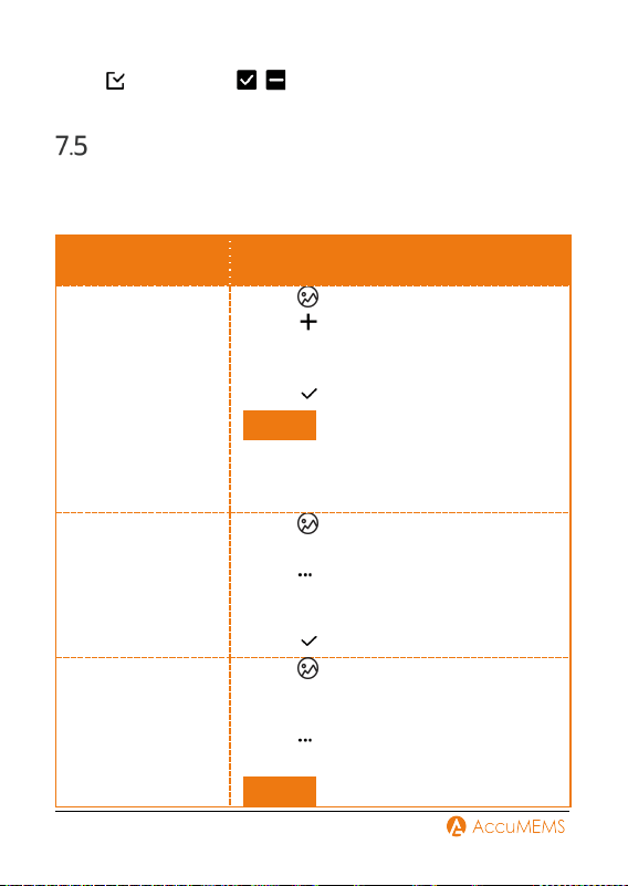
Manage Albums
Recorded image and video files are stored in Pictures. You can create
new albums, modify album names, change default albums, transfer files
between albums, and delete albums.
Task Operations
Create a New
Album
1.
Tap to enter Pictures.
2.
Tap to create a new album.
3.
A soft keyboard will appear for naming
the album.
4.
Tap to complete.
NOTE
The newly created album becomes the
default saving album and is displayed at
the top of the album list.
Rename an Album
1.
Tap to enter Pictures.
2.
Choose the album to rename.
3.
Tap , then choose Rename. A soft
keyboard will appear for renaming the
album.
4.
Tap to complete.
Set Default Saving
Album
1.
Tap to enter Pictures.
2.
Choose the album to set as default
saving location.
3.
Tap , then choose Set as Default
Saving Album.
NOTE
31
The default saving album is displayed at
the top of the album list.
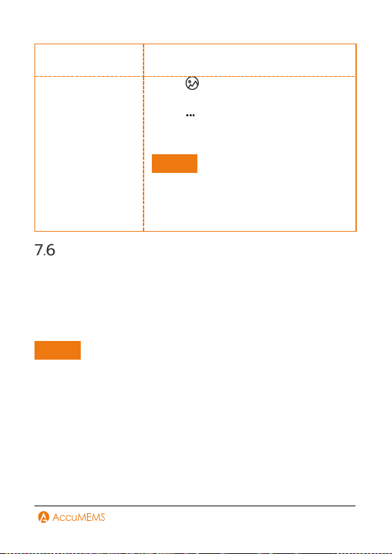
Delete an Album
1.
Tap to enter Pictures.
2.
Choose the album to delete.
3.
Tap , then choose Delete. A
confirmation dialog will appear.
4.
Tap OK to delete the album.
NOTE
Deleting an album also removes all files
within it. Transfer files to other albums if
needed. Refer to 7.4 Manage Files for
detailed instructions.
Export Files
1.
Connect the imager to your PC with the included USB cable.
2.
Select USB Drive mode in the prompt on imager.
3.
Open the detected disk, copy and paste the files to PC to view the
files.
4.
Disconnect the imager from your PC.
NOTE
For the first connection, the driver will be installed automatically.

32
8. Device Connection
Connect via Hotspot (If Applicable)
In the real-time interface, go to
More Config
Hotspot to
enable Hotspot. Remember download and install the APP on your
phone before using the function.
1.
Turn on the imager hotspot and complete settings.
-
Set the hotspot password.
-
Press
to save and exit.
2.
Use the APP to scan the hotspot's QR code to add the imager to the
app.
33
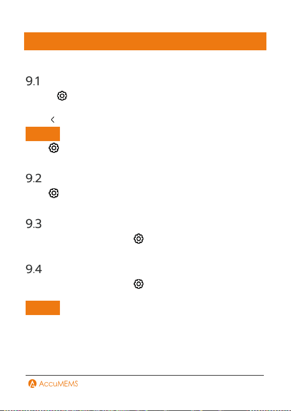
9. Maintenance
Time and Date Configuration
1.
Go to
Device Config
Time and Date.
2.
Set the Date and Time.
3.
Tap to save and exit.
NOTE
Go to
Display Config
Time and Date to turn on/off time and
date display.
Unit Configuration
Go to
Device Config
Unit to set the Temp. unit and Distance
unit.
View Imager Information
In the real-time interface, go to
More Config
About to view
the detailed information of the imager.
Format Memory
In the real-time interface, go to
More Config
Device
Initialization
Format Memory to initialize the storage.
NOTE
If files exist, ensure they are backed up before formatting. After
storage initialization, all data and files are permanently
unrecoverable.

34
Logs Configuration
The imager can retain its operational logs for troubleshooting
purposes. This function can be enabled/disabled via
More
Config
Save Logs.
To export logs:
1.
Connect the imager to a PC using the included USB cable.
2.
Set the imager's USB mode to USB Drive.
3.
Access operation logs in the device's root directory.
Upgrade
Before upgrade, download the upgrade file first. You can get the
upgrade file through technical support.
1.
Connect the imager to your PC via the included cable, and select
USB Drive as the USB mode in the prompt on the imager.
2.
Copy the upgrade file and replace it to the root directory of the
imager.
3.
Disconnect the imager from your PC.
4.
Reboot the imager and then it will upgrade automatically. The
upgrading process will be displayed in the main interface.
NOTE
After the upgrading, the imager automatically reboot. You can view
the current version in
More Config
About.
Restore Imager Configuration
In the real-time interface, go to
More Config
Device
Initialization
Restore Device
to initialize the imager and restore
default settings.

35
10. Guidance for Common
Thermal Imaging Operations
The manual provides guidance on common issues for first-time users of
imagers. For other questions or updated guidance, please contact
technical support.
Can the UIRA-Scene Algorithm Detect
Water Leaks, Insulation Issues or Heat
Irregularities with 100% Accuracy?
No, it does not achieve 100% accuracy. The UIRA-Scene algorithm is
designed for preliminary screening by analyzing thermal image
characteristics in various scenarios, based on clear images captured by
users. If an area is marked as "Suspect," we recommend manual
verification by professionals. Additionally, keeping your imager’s
firmware updated ensures access to the latest algorithm
enhancements.
Factors may Interfere with the
Detection Results of UIRA-Scene
Different wall materials and surrounding heat sources
Heat diffusion properties of different wall materials:
Some wall materials exhibit heat diffusion patterns that resemble
common wall defects, making it necessary for experienced
professionals to conduct further verification.
Interference from ambient heat sources (e.g., heaters or air
conditioning vents):
External heat sources may cause localized temperature increases on
wall surfaces, affecting detection accuracy.

36
Improve Water Leak Detection
Success Rates
Method
1.
Adhere to recommended leak area and detection distance
guidelines. Ensure the leak area and detection distance match your
imager’s IR resolution.
For example:
IR Resolution Distance Leak Area
96×96 ≤ 1m ≥ 10cm×15cm
96×96 ≤ 2m ≥ 20cm×30cm
256×192 ≤ 2m ≥ 10cm×15cm
256×192 ≤ 4m ≥ 20cm×30cm
Check your imager’s IR resolution under Specification.
2.
Perform multiple inspections and dynamic comparisons:
Relying on a single thermal image may lead to errors. Compare images
taken at different times (e.g., day vs. night), under varying temperature
conditions, or from different angles. You can also observe the same
area dynamically.
Higher-Quality Image
How to Take Clear Thermal Imaging Pictures?
Principle
Thermal image use colors to show temperature distribution. The

37
temperature range of the target affects the image effect.
Method
1.
When the actual temperature difference of the target in the image is
higher than 10 °C (50 °F) or 20 °C (68 °F), the thermal image effect is
most obvious, which helps to highlight the subtle temperature
difference.
2.
When the temperature difference of the target in the image is small,
you can manually adjust the temperature range (if applicable) of the
whole image to increase the contrast of the target.
3.
It is recommended that the distance between the imager and the
target should be within 2 meters (about 6.56 feet). Adjust the
distance to ensure clear focus, especially for small targets.
4.
Select an appropriate palette for the scene to get an image with high
contrast.
Guidance on Using Thermal Imaging
for Common Water Leak Detection
Principle
Water has a higher specific heat capacity than building materials, so the
temperature change rate of the leaking area is different from that of
the surrounding materials. The thermal imager captures this
temperature difference to locate the leak point contactlessly.
Tips
1.
Best Testing Time Period: Choose sunrise or sunset for testing. At
this time, the temperature difference between indoors and outdoors
is usually over 10 °C (50 °F), and the solar radiation heat gradient
makes the thermal imaging of leak points inside the wall more
obvious.

38
2.
Environmental Condition Control: The surface temperature should
be tested in dry and sunny weather. Rain and snow will lower the
surface temperature and interfere with the infrared signal, which will
seriously affect the accuracy of detection.
3.
Priority Detection Area: Scan the weak links of building structures
such as wall corners, window and door edges, existing cracks, pipe-
through wall holes, and connections, which are high-risk areas for
structural water leakage and pipe water leakage.
4.
Dynamic Verification: Avoiding false alarms caused by single-time
capture results. In the periods with significant day and night
temperature differences, or after adjusting different angles to
capture the same area multiple times. Dynamic verification can be
used to exclude false alarms.
NOTE
Structural Leakage Test: Spraying water on the wall to simulate
wetting, or testing the residual water-stained area immediately
after rain, can enhance the temperature difference contrast.
Pipe Leakage Detection: For persistent water leakage, you need to
take pictures during periods of water pressure changes (such as
before and after peak water usage) and refer to the specific
suggestions for pipe leakage detection.
Micro Leakage: if the water leakage is very small and the
temperature difference is not obvious, it is recommended to use
imagers with higher sensitivity and resolution (such as ≤40 mK
thermosensitivity and ≥256 × 192 resolution) to improve detection
rate.
Detect Water Pipe Leaks
How to Use Thermal Imaging for Hot Water Pipe Leaks?
Principle
When hot water pipes leak, heat energy will conduct to the surface of
buildings, and the leaked area will show as a high-temperature region

39
(usually in red or highlighted color) on the thermal image, which can
help you locate the leakage point.
Tips
1.
Time Selection: Select sunrise or sunset time when the environment
temperature changes significantly and helps to enhance the
temperature difference effect.
2.
Pressure Verification: Use the pipe pressure tester to monitor the
pressure change. If the pressure continues to decrease after
pressurization, it can be preliminarily confirmed that there is a leak.
3.
Temperature Difference Enhancement: Ensure the hot water
temperature is at least 10°C higher than the room temperature and
maintain the flow for 15-30 minutes. Under this condition, a
detectable temperature difference can be formed in concrete, wood
boards, or gypsum boards with a penetration depth of 3-5cm.
4.
Pathway Tracking: System scans along the hot water pipe route,
focusing on high-risk parts such as interfaces, valves, and wall-
penetrating holes, as well as historical maintenance records.
NOTE
The detection effect is influenced by water temperature (must be
10 °C higher than the indoor temperature), pipe burial depth
(concrete or dense materials over 5 cm deep may affect imaging), and
contact material (wooden boards or gypsum boards can be detected).
This method is applicable to contact heat transfer scenes. When
pipes have no physical contact with building structures or when
leakage water cannot penetrate to the surface, it will not be possible
to detect due to lack of temperature difference contrast.
How to Use Thermal Imaging for Detecting Leaks in Cold Water
Pipes?
Principle
Cold water leakage causes heat conduction to the wall, which results in

40
a lower temperature than that of the surroundings. The thermal imager
captures the temperature difference and displays it as a low-
temperature area (usually in blue).
Tips
1.
Time Selection: The temperature difference between cold water and
indoor temperature is usually small, and it is difficult for the
temperature to conduct to the surface. You can select sunrise or
sunset for testing, as the natural temperature difference can help
enhance the contrast.
2.
Pressure Verification: Use a pressurizing imager to monitor the
pressure of the pipe. If the pressure continues to drop, it can help
confirm that a leak exists.
3.
Operation in Winter: After preheating the wall and floor in the
heating environment, continuously supply cold water to the cold
water pipe to create a significant temperature difference.
4.
Operation in Summer: Inject cold water into the cold water pipe
during the low-temperature sunrise hours to enhance the test effects
by leveraging the temperature difference between the environment
and the water.
5.
Temperature Difference Strengthening Method: Pour hot water
into the cold water pipe and keep it for 15 minutes (refer to the hot
water pipe testing tips), which can quickly generate a recognizable
temperature difference.
NOTE
The detection effect is influenced by water temperature (must be
10 °C higher than the indoor temperature), pipe burial depth
(concrete or dense materials over 5 cm deep may affect imaging), and
contact material (wooden boards or gypsum boards can be detected).
This method is applicable to contact heat transfer scenes. When
pipes have no physical contact with building structures or when
leakage water cannot penetrate to the surface, it will not be possible
to detect due to lack of temperature difference contrast.

41
Can the Thermal Imager Penetrate
Walls or Floors?
No. Thermal imagers cannot penetrate walls or floors like X-ray
machines. They can only detect heat emitted from the surface of an
object. However, in certain cases, the thermal imager can detect
anomalies inside walls or floors, such as water pipe leakage or heat loss
due to poor insulation. This is because the thermal imager can capture
the heat conducted to the surface of the wall or floor. If the pipe has no
contact with the wall or ground, the temperature cannot be conducted,
and the thermal imager cannot detect it.
Check a Thermal Imager’s
Temperature Accuracy
How to test the accuracy of the imagers?
Tips
1.
Pour crushed ice and water into the cup, and turn on the imager.
2.
Mix the solution and let it stand for a few minutes.
3.
Set the imager's emissivity to 0.95 and adjust the distance.
4.
Point the imager at the solution to measure its temperature. To get
the best effect, please measure the temperature of water surface and
avoid measuring cup wall. The reading should be close to the freezing
point (0 °C / 32 °F) and within the precision range.
Frozen Images
What are the clicking sound and frozen image after imager startup?
This is a normal phenomenon of the thermal imaging imager. To keep
the measurement accuracy, the imager will automatically calibrate the
environment temperature change. During this process, the screen may
stutter and show "Image Calibrating…", and you can also hear a "click"
sound from the imager. This phenomenon usually occurs when the

42
imager is moved quickly or when it is turned on for the first time.
Prolong Battery Life
How to extend the life of lithium batteries?
Tips
1.
Initial Charging: Charge the imager for 3 hours in the off state
before first use.
2.
Charging Cable: Use the included charging cable or an authenticated
one.
3.
Power Adapter: For best results, use a standard 5 V/2 A charger.
4.
Storage and Reuse: When storing the imager for a long time, charge
it to full capacity every 3 months. Before using the imager after
storage, turn off the imager and charge it for at least 30 minutes.

43
REGULATORY INFORMATION
FCC Compliance Statement
Please take attention that changes or modification not expressly
approved by the party responsible for compliance could void the user's
authority to operate the equipment.
This device complies with Part 15 of the FCC Rules. Operation is
subject to the following two conditions:
(1) This device may not cause harmful interference, and
(2) This device must accept any interference received, including
interference that may cause undesired operation.
This equipment complies with FCC radiation exposure limits set forth
for an uncontrolled environment.
Note: This product has been tested and found to comply with the limits
for a Class B digital device, pursuant to Part 15 of the FCC Rules.
These limits are designed to provide reasonable protection against
harmful interference in a residential installation. This product
generates, uses, and can radiate radio frequency energy and, if not
installed and used in accordance with the instructions, may cause
harmful interference to radio communications. However, there is no
guarantee that interference will not occur in a particular installation. If
this product does cause harmful interference to radio or television
reception, which can be determined by turning the equipment off and
on, the user is encouraged to try to correct the interference by one or
more of the following measures:
—
Reorient or relocate the receiving antenna.
—
Increase the separation between the equipment and receiver.
—
Connect the equipment into an outlet on a circuit different from that
to which the receiver is connected.

44
—
Consult the dealer or an experienced radio/TV technician for help.
The highest SAR value reported under this standard during product
certification when properly body worn (5mm) is 1.06 Wkg.

AccuMEMS
OFFICE
Hangzhou Accumems Technology Co., Ltd.
www.accumems.com
Office Address
Room 418-1, Building 2, JinxiuLinglongfu,
Xixing Street, Binjiang District,
Hangzhou City, Zhejiang Province
GuidePost
Firmware Upgrade