RELIABLE EFFICIENT VALUE
315-750-4008
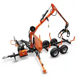
HYDRAULIC
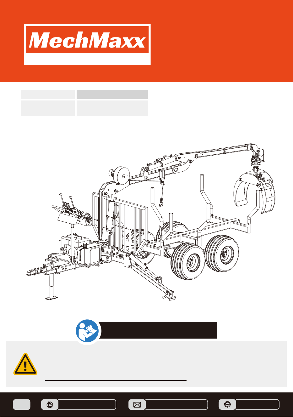
LOG TRAILER
WITH CRANE
This manual contains important safety precautions. Read and understand this manual carefully
before using the product. Failure to follow these instructions may result in serious injury.
The specifications, descriptions, and illustrations in this manual are as accurate as possible at
the time of publication, but are subject to change without notice.
Keep this manual with the product for future reference.
www.mechmaxx.com
150603 SKU
Model LT4400
OPERATOR’S MANUAL
EN

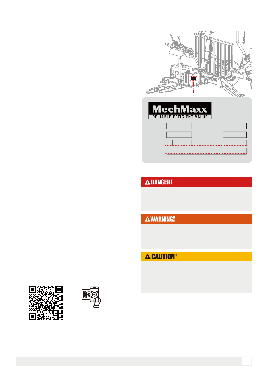
Boom Reach:
Year:
Engine: Lift Capacity:
Serial No.:
Model:
Load Capacity:
LOG
TRAILER
www.mechmaxx.com
HYDRAULIC LOG TRAILER WITH CRANE
Before operating the machine, please read this
manual carefully and make sure you understand all
safety warnings, assembly instructions, operating
procedures, maintenance requirements, and
troubleshooting information. Proper assembly, safe
operation, and regular maintenance will help ensure
reliable performance, extend the service life of the
machine, and reduce the risk of personal injury or
equipment damage.
The illustrations and specifications in this manual
are for reference only. The actual product may vary
slightly due to model configuration, production
updates, or technical improvements. If you have any
questions during assembly, operation, or mainte-
nance, stop using the machine and contact your
dealer or service representative for assistance.
This machine is designed for specific applications
only. We strongly recommend that this machine not
be modified or used for any application other than
its intended purpose. If you have any questions
regarding a particular application, DO NOT use the
machine until you have contacted us to determine
whether the application can or should be performed
with this product.
Use only genuine MechMaxx parts when servicing or
repairing this machine. Replacement parts
manufactured by other companies may fit this
machine, but they may present potential safety
hazards. Replacement parts can be purchased from
your authorized MechMaxx dealer.
• The serial number of your machine
• The part number
• The part description
• The quantity needed
1
INTRODUCTION
INTRODUCTION
Indicates an imminently hazardous situation
which, if not avoided, will result in death or
serious injury.
SCAN THE QR CODE TO
CONTACT US
Indicates a potentially hazardous situation which,
if not avoided, could result in death or serious
injury.
Indicates a potentially hazardous situation which,
if not avoided, may result in minor or moderate
injury. It may also be used to alert against unsafe
practices.
Ordering Parts
Safety Definitions

HYDRAULIC LOG TRAILER WITH CRANE
TABLE OF CONTENTS
TABLE OF CONTENTS
TABLE OF CONTENTS
SPECIFICATIONS
SAFETY SIGNS
SAFETY
2
3
Operation Symbols
7
Add Hydraulic Oil
Hydraulic Oil Drain
29
Changing The Engine Oil
28
29
Hydraulic Filter Replacement
29
Greasing
30
Maintenance Schedule
31
Transport Safety
33
Tightening Torque
32
Attach to a Tow Vehicle
34
Trailer Jack
34
STORAGE
35
Storage Safety
35
TROUBLESHOOTING
36
HYDRAULIC SYSTEM DIAGRAM
38
PARTS DIAGRAM
39
Grapple Assembly
39
Engine Assembly
41
Rear Boom Assembly
48
Personal Safety
Special Safety Instructions
Maintenance Safety
8
Work Area Safety
8
8
9
Hydraulic Safety
10
10
11
Refueling Safety
Storage Safety
ASSEMBLY
12
KNOW YOUR MACHINE
19
Know Your Engine
20
Add Hydraulic Oil
Start the Engine
Stopping the Engine
4
8
21
21
22
21
22
23
Controls
24
Log Trailer Start-Up
25
Load the Log Trailer
25
Log Trailer Shutdown
26
OPERATION
Add Oil to Engine
Add Fuel
28
MAINTENANCE
28
Spark Plug
33
TRANSPORT
33
Prepare the Machine for Transport
44
Right Axle Bracket Assembly
45
Left Axle Bracket Assembly
46
Vertical Boom Assembly
Winch Assembly
51
50
Front Frame Guard Assembly
2

HYDRAULIC LOG TRAILER WITH CRANE
SPECIFICATIONS
3
SPECIFICATIONS
Model LT4400 (150603)
Engine
Displacement
Maximum Hydraulic Pressure
Pump Displacement
Crane Arm Length
Lifting Capacity at Max. Reach
Swing Angle
Max. Trailer Load Capacity
Hydraulic Winch Remote Control Range
Hydraulic Oil Tank Capacity
Tire Size
Max. Lifting Height
Hydraulic Fluid Operating Temperature
Overall Dimensions (L x W x H)
Packing Size (L x W x H)
Ducar DH212
212 cc; 7 HP
2,321 psi
0.165 in³/rev
10.6 ft
440 lb
±90°
4,400 lb
98.4 ft
3.17 US gal
23 x 10.5 -12 in
11.5 ft
-22°F to 176°F
166.1x 105.5 x 76.8 in
90.3 x 47 x 29.1 in
HYDRAULIC LOG TRAILER WITH CRANE
4
SAFETY SIGNS
SAFETY SIGNS
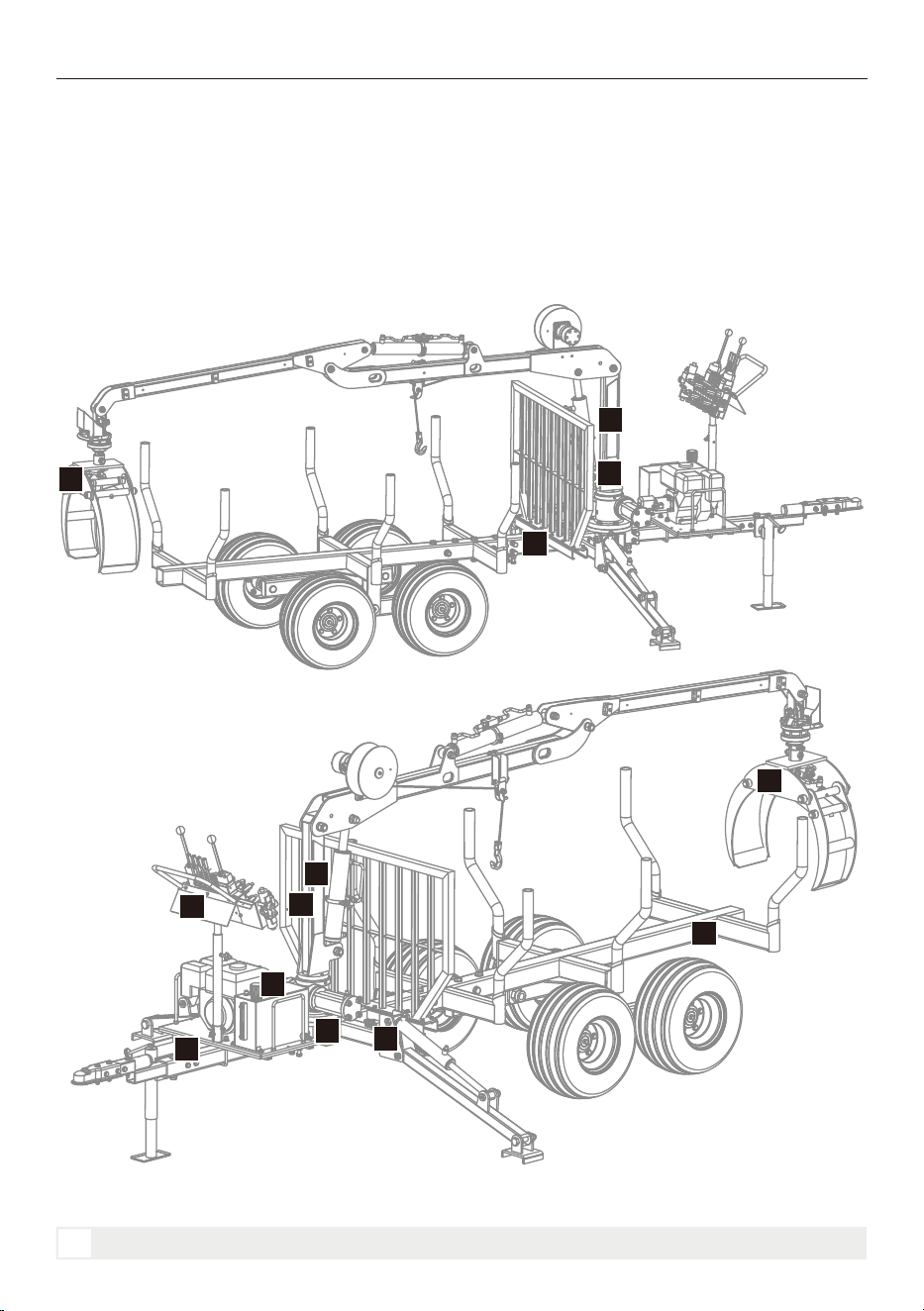
The SAFETY SYMBOL indicates a potential personal-injury hazard. When you see this symbol, be alert, read the
message that follows, and take the required safety precautions. In addition to design and configuration of
equipment, hazard control and accident prevention are dependent upon the awareness, concern, prudence and
proper training of personnel involved in the operation, transport, maintenance and storage of equipment.
1
2
9
8
3
5
7
7
6
5
5
4
1
HYDRAULIC LOG TRAILER WITH CRANE
5
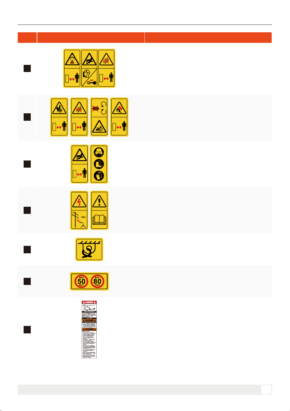
HYDRAULIC CRANE SAFETY WARNING
Keep clear of suspended loads, high-pressure
hydraulic fluid, pinch points, and moving parts. Read
the operator’s manual and remove the ignition key
before maintenance.
PINCH & CRUSH HAZARD WARNING
Keep hands and body clear of pinch, crush, and
rotating hazards. Maintain a safe distance during
operation.
HYDRAULIC INJECTION & PPE WARNING
Keep clear of high-pressure hydraulic leaks. Wear
eye protection, safety boots, and protective gloves.
ELECTRICAL HAZARD & SAFETY WARNING
Keep at least 50 ft (15 m) away from overhead power
lines.
LIFTING POINT
Attach lifting slings or hooks at the designated point
for safe lifting.
LABEL MEANING
SAFETY SIGNS
MAXIMUM TOWING SPEED
Do not exceed 50 mph (80 km/h) during towing or
transport.
CRANE OPERATION & GENERAL SAFETY WARNING
Keep clear of overhead power lines and the crane
operating area. Read the manual, observe load limits,
keep bystanders away, and secure the boom before
transport.
1
2
3
4
5
6
7

HYDRAULIC LOG TRAILER WITH CRANE
6
LABEL MEANING
SAFETY SIGNS
PINCH POINT & STABILIZER WARNING
Keep hands and limbs clear of pinch points. Fully
deploy stabilizers before operating the crane.
HYDRAULIC CRANE CONTROL FUNCTIONS
Shows the control directions for crane movement,
grapple rotation/opening, boom operation, and
stabilizer adjustment.
8
9
HYDRAULIC LOG TRAILER WITH CRANE
Operation Symbols
ONOFF
OPENCLOSED
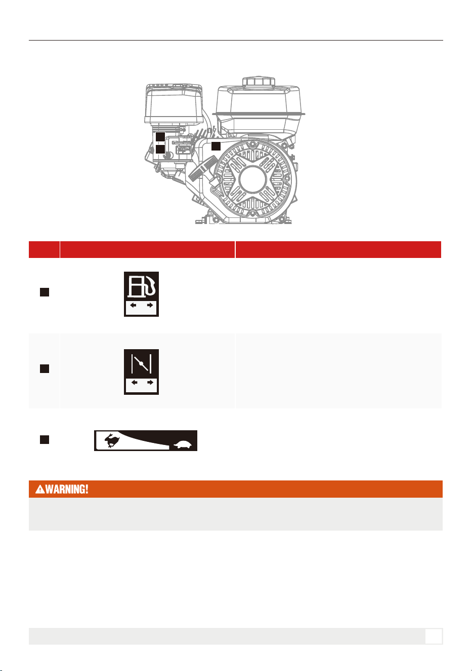
The symbols and their positions shown may differ from those on the actual engine. If there is any difference,
refer to the actual engine markings and positions, and read the engine manual carefully before operation.
These safety labels are designed to help you operate the machine safely. Read and follow all label instructions.
1. Keep all safety labels clean and legible.
2. Replace all damaged or missing labels.
3. Some new equipment installed during repair requires safety labels to be affixed to the replaced component as
specified by MechMaxx. When ordering new components make sure the correct safety labels are included in the
request.
FUEL SWITCH LABEL DESCRIPTION
This label indicates the fuel valve control position.
Move the switch to ON to allow fuel flow before
starting, and move it to OFF to shut off the fuel
supply when the machine is not in use.
CHOKE CONTROL LABEL DESCRIPTION
This label indicates the choke control position. Move
the lever to CLOSED for cold starting, and move it to
OPEN after the engine starts or during normal
operation.
THROTTLE CONTROL LABEL DESCRIPTION
This label indicates the engine speed control. Move
the lever toward the rabbit symbol to increase speed,
and toward the turtle symbol to decrease speed.
LABEL MEANING
A
B
C
7
SAFETY SIGNS
A
B
C

HYDRAULIC LOG TRAILER WITH CRANE
SAFETY
Read and understand the separate Engine Manufac-
turer’s manual supplied with this unit. Do not
operate the machine until you fully understand how
to properly operate and maintain the engine.
Do not operate, adjust, or maintain any equipment
when tired. Parts of this trailer must not be used,
adjusted, or serviced while under the influence of
fatigue, drugs, alcohol, or medication.
Wear protective clothing suitable for the work
environment and equipment.
Use hearing protection with an appropriate noise
reduction rating.
Avoid wearing clothing or jewelry that may become
entangled.
Keep hair covered and tied back during work.
Use suitable protective gloves for the task.
Keep fingers away from pinch points around
materials.
Do not overreach during operation. Use non-slip
footwear.
Only trained, responsible adults who can safely
control the equipment may operate the machine. Do
not operate when fatigued, impaired, or unable to
maintain proper balance and control.
Failure to follow these instructions may result in
serious accidents or injuries.
Wet, slippery, uneven, or steep terrain is potentially
hazardous. Operating this machine on hazardous
terrain may result in serious injury. Safe operation
requires reduced speed and careful route selection
based on terrain conditions.
• This log trailer must only be used for its intended
purpose and under the conditions described in the
operator’s manual.
The operator is responsible for preventing accidents
or injuries to themselves, other people, animals, and
property.
Assemble, adjust, and operate the product only in a
safe working environment.
Keep the work area clean and free from distractions.
Keep all persons without protective equipment out
of the work area.
If working alone, arrange for someone to check on
your safety at regular intervals.
Do not allow children or pets in the work area. Do
not allow children or pets on or near the equipment.
Do not operate the equipment in the presence of
flammable gases or vapors, combustible dust, or
flammable liquids.
Read and understand this manual and all safety
labels before operating the Hydraulic Log Trailer
with Crane. Failure to follow these safety instruc-
tions may result in serious injury, death, or property
damage.
Work Area Safety
Special Safety Instructions
Personal Safety
Read and understand this manual
and all safety labels attached to the
machine before operation. Become
familiar with the machine’s
controls, limitations, proper
operation, and potential hazards.
If this machine is loaned, rented, sold, or used by
someone other than the original purchaser,
always provide this manual and proper safety
training before operation.
Always wear proper personal protective
equipment during operation, including safety
glasses with side shields, hearing protection,
gloves, heavy long pants, and protective
footwear.
8
SAFETY

HYDRAULIC LOG TRAILER WITH CRANE
• The operator must use proper judgment,
knowledge, and experience to ensure safe operation
of the equipment. Always adjust operating speed
according to terrain, load, visibility, and other
conditions.
• Do not use the equipment for any purpose other
than its intended use.
• Do not use the trailer if any components are
damaged.
• When disconnecting the trailer from the towing
vehicle, ensure that the trailer is secured and cannot
move after being detached.
• Inspect the tires after each use and before
servicing. If necessary, contact a qualified
technician to ensure that the trailer and its
components are in proper working condition.
• Always deploy and securely engage the stabilizer
legs before operating the crane to improve stability.
• Assembly, maintenance, and repair of the log trailer
must only be performed by persons with sufficient
mechanical skills and experience in the safe
handling of the equipment.
• Ensure that the ATV or UTV is turned off and the
brakes are engaged before connecting, loading, or
unloading the trailer.
• Operate only on safe and familiar terrain.
• Reduce speed and be prepared to stop while
towing, especially on wet or slippery surfaces.
• Avoid loose clothing and jewelry. Long hair must
be tied back or covered to prevent entanglement in
moving parts.
• Refer to the engine manual for important
information regarding fire hazards.
• Immediately clean up any fuel or oil spills before
starting the engine.
• THE ENGINE IS SUPPLIED WITHOUT ENGINE OIL!
• Add the correct engine oil before use.
• Do not touch the engine while it is hot.
• The engine can become extremely hot during
operation.
• Check the engine oil level before each use.
• Use clean, fresh, unleaded gasoline with a
minimum pump octane rating of 87 AKI (91 RON).
Gasoline containing up to 10% ethanol (E10) is
acceptable.
• Fuel may damage painted surfaces and certain
types of plastic.
• Never operate the engine if it is leaking fuel or oil.
Avoid spilling fuel when refueling.
• Never refuel a hot engine.
• Never operate the engine without the air filter
installed.
• Turn off the engine and allow it to cool before
adding oil or gasoline.
• Do not fill the fuel tank in an enclosed area, such
as a garage. Do not refuel while smoking or near
open flames, sparks, or other ignition sources.
• Avoid getting the air filter wet during operation.
• Ensure the fuel cap is securely tightened to prevent
leakage.
• Do not use compressed air to clean the air filter.
1. Proper maintenance is your responsibility. Poor
maintenance can lead to equipment failure, unsafe
operation, and costly repairs.
2. Follow good shop practices:
• Keep the work area clean and dry.
• Ensure electrical outlets and tools are properly
grounded.
• Use adequate lighting for the task.
3. Provide adequate ventilation. Never operate the
engine or towing vehicle in an enclosed area.
Exhaust fumes can cause serious injury or death.
4. Place the machine in a safe condition before
performing maintenance:
• Close the grapple and rest it securely on the trailer.
• Install the boom pin lock.
• Shut off the engine.
• Turn off the fuel valve.
• Ensure the load is secure.
• Secure the trailer to prevent movement.
5. Allow the engine to cool before servicing. Engine
components and fluids may become hot enough to
cause burns.
6. Never work under raised equipment unless it is
securely supported or blocked.
Maintenance Safety
9
SAFETY

HYDRAULIC LOG TRAILER WITH CRANE
7. Wear appropriate personal protective equipment
(PPE) during service or maintenance, including:
• Safety glasses
• Protective gloves
• Hearing protection
• Safety footwear
8. Use only approved replacement parts. Genuine or
equivalent replacement parts must be used to
maintain the original equipment specifications and
safe operation. The manufacturer is not responsible
for injury or damage resulting from the use of
unapproved parts or accessories.
9. Keep a fire extinguisher and first-aid kit readily
accessible when performing maintenance or service.
10. Inspect and tighten all bolts, nuts, and screws.
Check all electrical, hydraulic, and fuel connections
to ensure they are secure and in good condition
before operation.
11. After completing maintenance or service,
reinstall all guards, shields, and safety devices
before returning the machine to operation.
12. When performing maintenance, have at least two
people present whenever possible. Do not work
alone during emergency-prone or hazardous service
procedures.
13. Use only approved cleaning agents. Do not use
gasoline or other flammable solvents for cleaning.
14. Use proper tools that are in good condition.
Make sure you understand how to use them correctly
before performing service work.
15. Keep all body parts away from pinch points and
moving components during assembly, installation,
maintenance, adjustment, or repair.
16. Disconnect the spark plug wire before servicing
the engine or equipment to prevent accidental
starting.
1. Keep all hydraulic system components clean and
in good condition.
2. Before pressurizing the hydraulic system, inspect
all components. Make sure fittings are tight and that
hydraulic lines, hoses, and couplings are not
damaged, worn, or leaking.
3. Never make temporary repairs to hydraulic lines,
fittings, or hoses using tape, clamps, cement, or
similar materials. Hydraulic systems operate under
extremely high pressure, and improper repairs may
fail suddenly and create a serious hazard.
4. Wear appropriate hand and eye protection when
checking for hydraulic leaks. Never use your hands
to locate a leak. Use a piece of wood or cardboard to
help detect and identify high-pressure leaks.
5. Always relieve hydraulic system pressure before
performing maintenance, inspection, adjustment, or
repair.
1. Store fuel only in approved safety containers.
2. Do not smoke while refueling.
3. Handle fuel with care. Gasoline is highly
flammable.
4. Refuel outdoors whenever possible. If refueling
indoors, make sure the area is well ventilated.
5. Never refuel while the engine is running.
6. Allow the engine to cool for at least 5 minutes
before refueling.
7. Keep the machine free of accumulated grass,
grease, fuel, and debris to reduce the risk of fire.
8. Never store, spill, or use gasoline near open
flames, sparks, pilot lights, stoves, furnaces, water
heaters, or other ignition sources.
9. Do not start or operate the engine if gasoline has
been spilled. Clean up spilled fuel immediately.
10. Move the machine away from the spill area and
avoid creating any source of ignition until all fuel
vapors have dissipated.
Hydraulic Safety
Refueling Safety
10
SAFETY
High-pressure hydraulic fluid can penetrate the
skin and cause serious injury. If hydraulic fluid is
injected into the skin, seek immediate medical
attention. Serious infection, tissue damage, or
toxic reaction may occur.
Fuel vapors can ignite or explode, causing
serious injury or death. Do not smoke while
refueling. Keep sparks, open flames, and hot
surfaces away from fuel.

HYDRAULIC LOG TRAILER WITH CRANE
1. Store the machine in a secure area away from
unauthorized persons and general activity.
2. Do not allow children to play on, near, or around
the stored machine.
3. Store the machine on a dry, level, and stable
surface. Support or block the frame securely if
necessary to prevent movement or tipping.
4. For long-term storage, follow the engine
manufacturer's instructions for proper engine and
fuel system storage.
Storage Safety
Even if certain safety precautions are not
specifically mentioned above, always remain
alert, follow safe operating practices, and
operate the machine properly according to this
manual and the engine manual.
11
SAFETY
HYDRAULIC LOG TRAILER WITH CRANE
ASSEMBLY
12
This is a complex and potentially dangerous machine. The log trailer and its components may present serious
hazards if assembled incorrectly. If you are not fully confident in your ability to complete the assembly safely,
seek assistance from a qualified technician.
The trailer is delivered mostly pre-assembled; however, the main components must be installed by the user or a
qualified technician. Follow these instructions carefully to ensure proper and safe assembly.
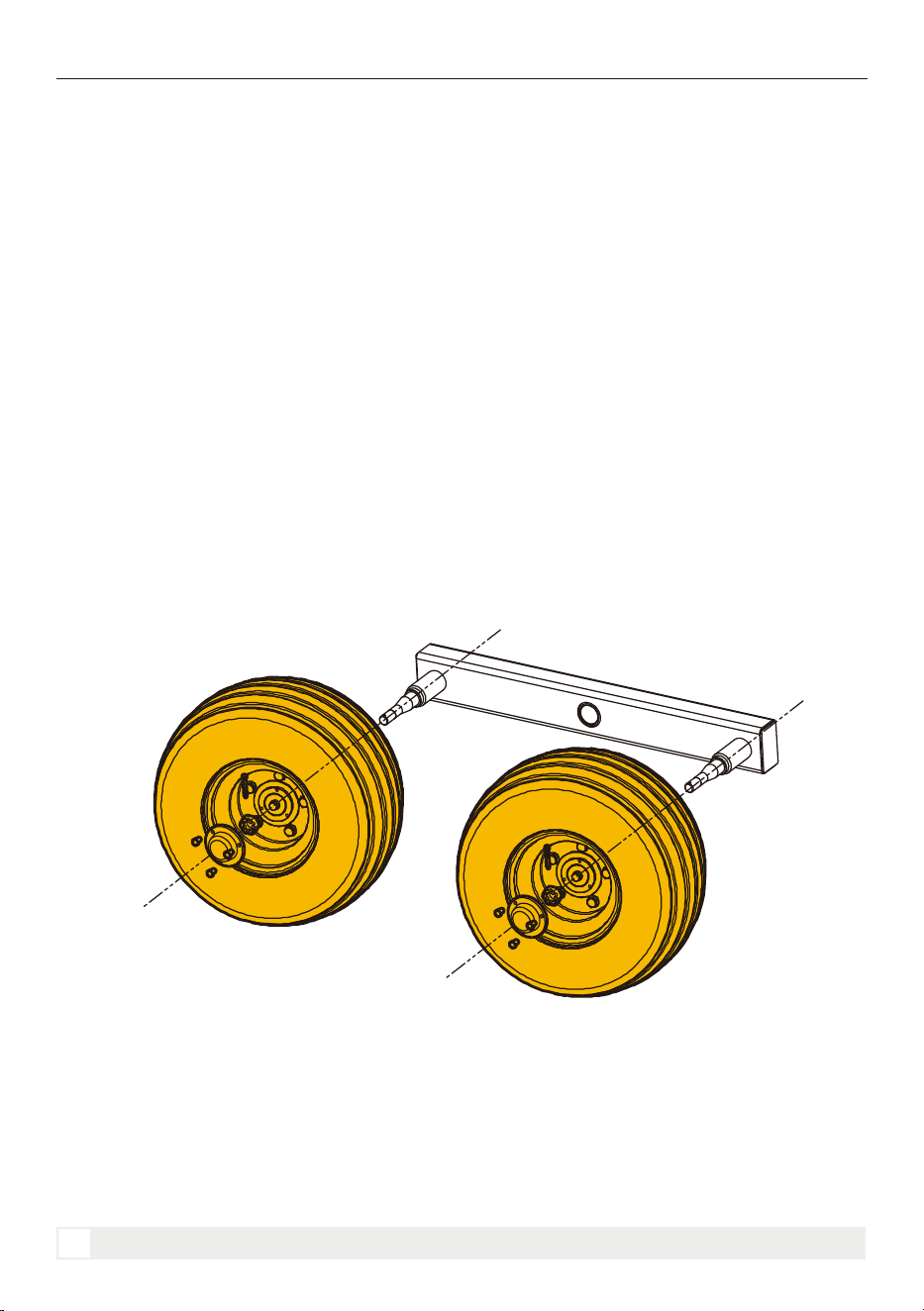
4. Position the wheel onto the axle spindle and slide it fully into place. Install the castle nut and tighten it while
ensuring that the wheel can still rotate freely. Align a slot in the castle nut with the hole in the axle, then insert
the cotter pin to secure the nut. Finally, install the hub cap. Repeat the same procedure for the wheel on the
opposite side.
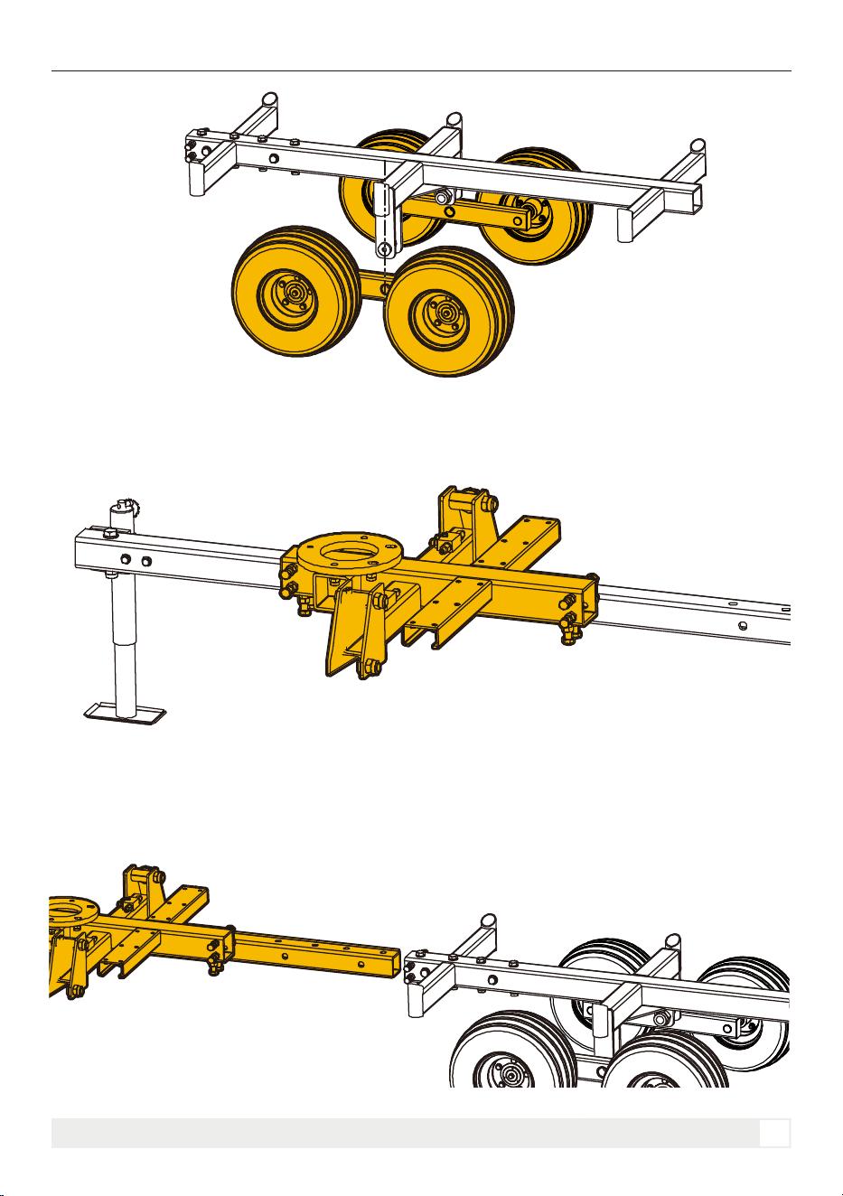
5. Move the wheel assembly into position beneath the frame and align the mounting holes with the correspond-
ing holes on the frame. Secure the wheel assembly using the appropriate bolts, washers, and nuts, then tighten
all fasteners securely. After installation, check that the wheel assembly is firmly attached, properly aligned, and
that the wheels rotate freely without interference.
1. Open the shipping crate. Remove all straps and protective coverings.
2. Unpack the accessible parts. Once the cover is removed, carefully lift each part out of the crate and set it
aside. Group similar parts together for easy identification.
The trailer and its components are heavy. At least two people are recommended for unpacking, lifting, moving,
and assembly. Always use proper lifting techniques in accordance with applicable occupational safety
guidelines.
3. Verify the contents of the crate. Confirm that all components match the parts list and that the quantities are
correct. If any parts are missing or damaged, contact the dealer as soon as possible.
Install the Wheel onto the Axle
Install the Wheel Assembly to the Frame
ASSEMBLY
HYDRAULIC LOG TRAILER WITH CRANE
13
6. Pass the base joint assembly through the drawbar and align the mounting holes. Secure it in place using the
appropriate bolts and nuts.
Base Joint Installation
7. Install the drawbar onto the trailer frame. Position the drawbar assembly near the front of the frame. With the
assistance of another person, tilt the trailer frame and slowly move it toward the drawbar assembly. Guide the
drawbar assembly into the trailer frame and align the mounting holes. Install the appropriate fasteners and
tighten them to the torque specified for the bolt size.
Drawbar Installation
ASSEMBLY
HYDRAULIC LOG TRAILER WITH CRANE
14
ASSEMBLY
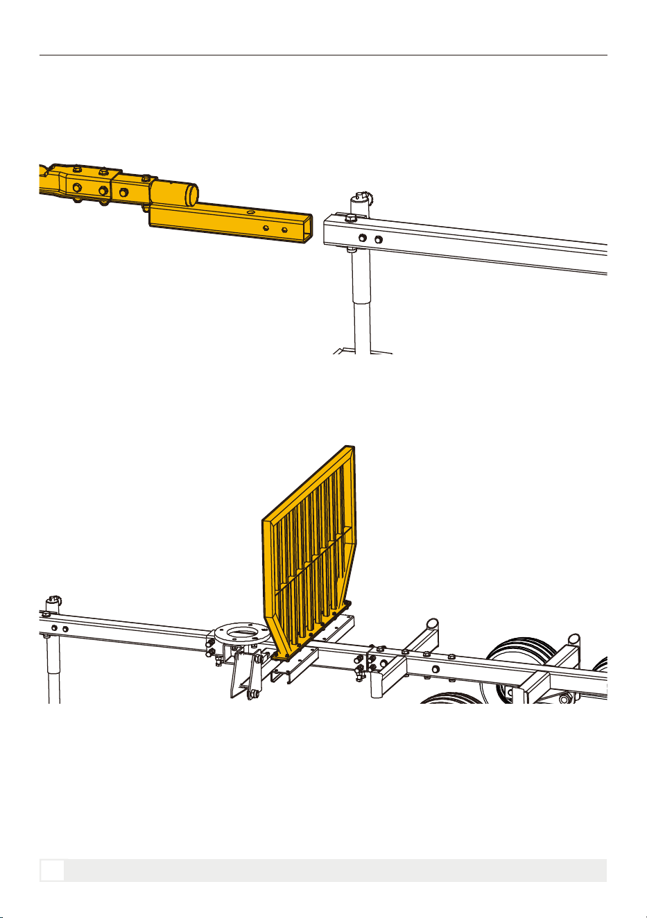
8. Attach the trailer coupler to the drawbar. Align the mounting holes, install the appropriate bolts and nuts, and
tighten the fasteners to the specified torque for the bolt size.
Trailer Coupler Installation
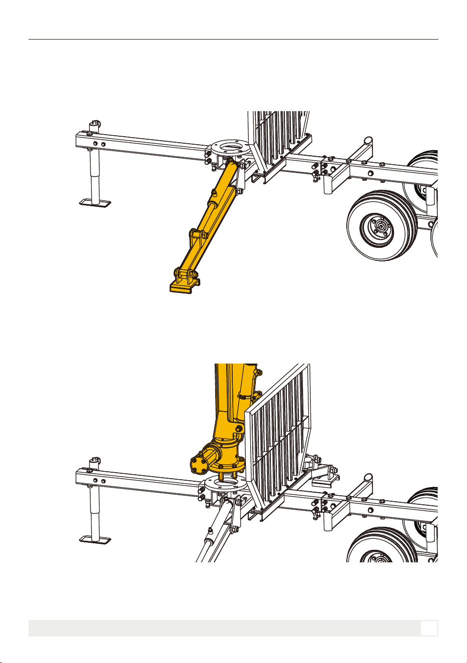
9. Position the safety guard on the frame base and align the mounting holes. Install the appropriate fasteners
and tighten them evenly to a torque of 230–258 N·m (170–190 lb-ft).
Safety Guard Installation
HYDRAULIC LOG TRAILER WITH CRANE
15
ASSEMBLY
10. Align the stabilizer leg with the mounting holes on the frame base, then insert the pivot pin. Because the
stabilizer leg must remain movable, tighten the nut only until it just contacts the bottom of the pivot pin. Lower
the stabilizer leg so that it rests flat on the ground. Connect the hydraulic hose after installation to help prevent
oil leakage from the cylinder.
Stabilizer Leg Installation
11. Position the vertical boom assembly on the stabilizer frame base and align the mounting holes. Secure it
using the appropriate bolts and nuts, then tighten all fasteners to the specified torque for the corresponding bolt
size.
Vertical Boom Assembly Installation
HYDRAULIC LOG TRAILER WITH CRANE
16
ASSEMBLY
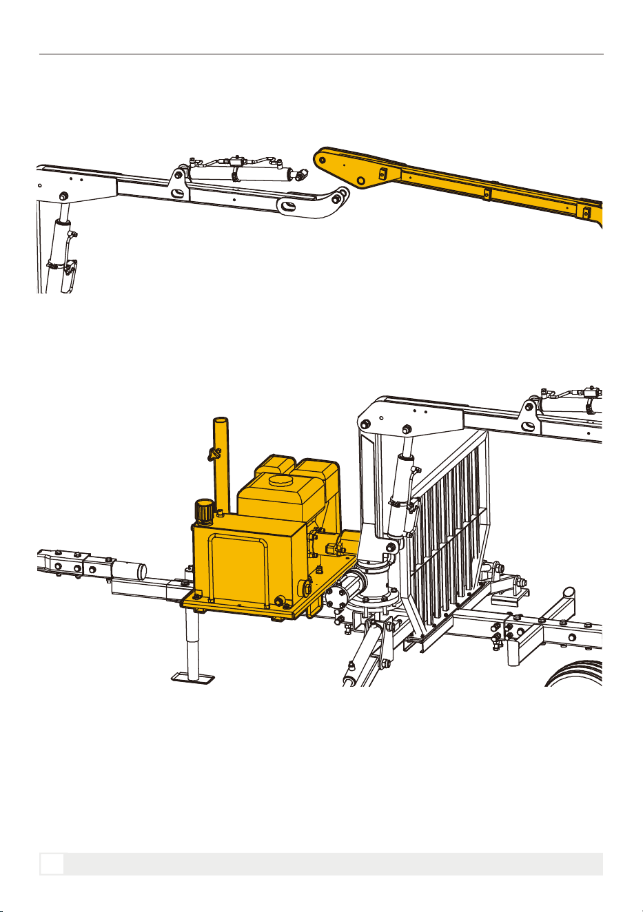
12. Install the boom onto the vertical boom assembly as shown. Because the boom must move freely, tighten the
nuts only until they just contact the shoulder of each pivot pin.
Boom Installation
13. With the assistance of another person, position the engine on the drawbar in front of the stabilizer frame
base. Secure the engine to the drawbar using the two engine-mount U-brackets. Tighten the fasteners until the
lock washers are fully compressed. Do not overtighten, as excessive tightening may bend the U-brackets.
Engine Installation
HYDRAULIC LOG TRAILER WITH CRANE
17
ASSEMBLY
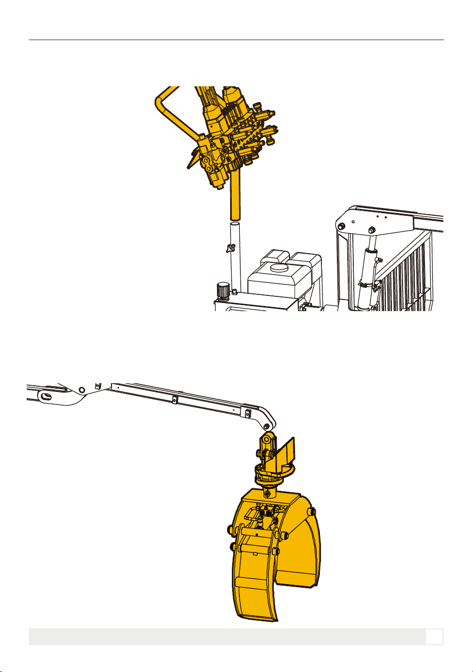
14. Insert the control support rod into the engine base sleeve and secure it with the mounting bolt. Hand-tighten
the bolt.
Hydraulic Control Panel Installation
15. Remove the pivot pin from the end of the boom assembly. Position the grapple so that its hydraulic hose
fittings are oriented for connection to the boom hoses, then align the mounting holes between the grapple
connector and the boom. Insert the pivot pin and install the nut. Because the grapple joint must move freely,
tighten the nut only until it just contacts the bottom of the pivot pin.
Grapple Installation
HYDRAULIC LOG TRAILER WITH CRANE
18
ASSEMBLY
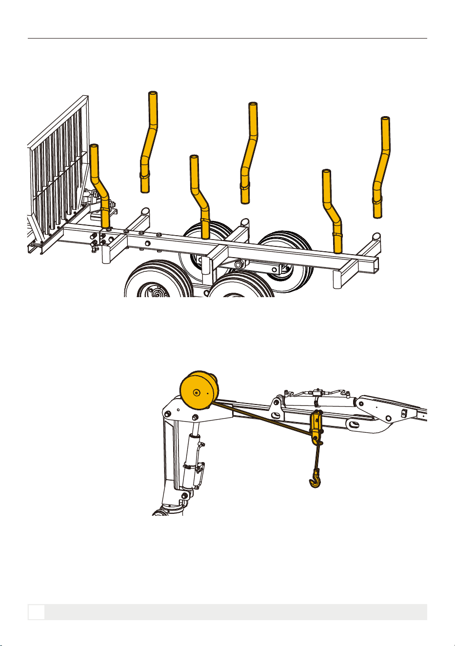
16. Insert the six support bars into the frame. Ensure that the curved side of each support bar faces outward.
Support Bar Installation
17. Install the winch on top of the vertical boom assembly, and install the wire-rope guide bracket at the middle
of the main boom. Secure both components with the appropriate fasteners. Route the wire rope along the boom
as shown, ensuring that it is properly seated in the pulley groove and is free from twisting, binding, or interfer-
ence.
Winch Installation
HYDRAULIC LOG TRAILER WITH CRANE
KNOW YOUR MACHINE
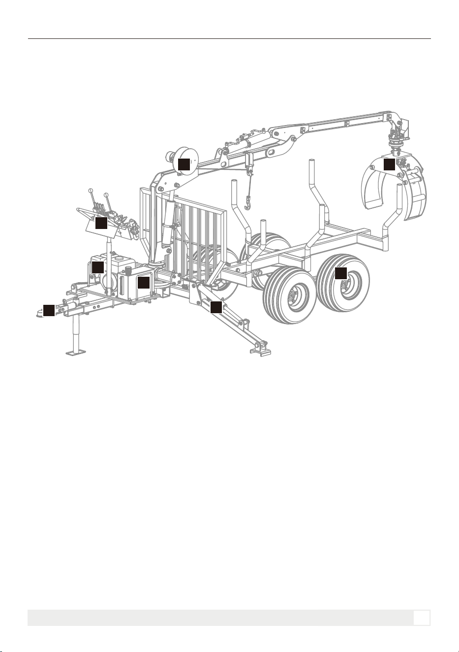
Before operating the Hydraulic Log Trailer with Crane, read this operator's manual carefully.
1. Tow Bar: Connects the trailer to the towing
vehicle for transport.
2. Hydraulic Oil Tank: Stores hydraulic oil for the
hydraulic system.
3. Hydraulic Control Panel: Controls the boom,
grapple, and other hydraulic functions.
4. Winch: Used to pull or assist in lifting logs and
other heavy materials.
5. Grapple: Used to grab, lift, and load logs or other
materials.
6. Wheels: Support the trailer and allow it to be
towed.
7. Stabilizer Legs: Provide support and stability
during operation.
8. Engine: Provides power to operate the hydraulic
system.
1
2
3
4
5
6
7
8
19
KNOW YOUR MACHINE
HYDRAULIC LOG TRAILER WITH CRANE
Know Your Engine
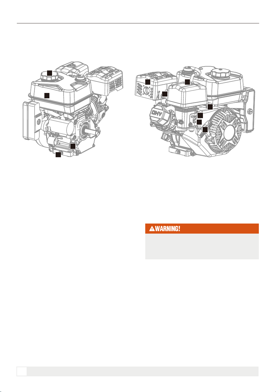
Before starting the engine, become familiar with your engine first. The information shown in this section may
differ from the actual engine on your machine. If there is any difference, please refer to the engine manual.
1. Fuel Filler Cap: Used to fill fuel into the tank.
2. Fuel Tank: Stores fuel for engine operation.
3. Oil Drain Plug: Used to drain engine oil.
4. Oil Filler Cap / Dipstick: Used to add and check
engine oil.
5. Muffler: Reduces engine exhaust noise and
releases exhaust gas.
6. Spark Plug: Ignites the fuel-air mixture to start the
engine.
7. Air Cleaner: Filters air before it enters the engine.
8. Fuel Valve Lever: Opens or closes the fuel supply.
9. Choke Lever: Helps start the engine when cold.
10. Throttle Lever: Controls the engine speed.
11. Recoil Starter: Used to start the engine by
pulling the starter handle.
4
3
2
1
11
5 7
6
9
8
10
20
KNOW YOUR MACHINE
If there is any difference from the actual engine,
refer to the actual engine manual and read the
engine manual carefully before operation.
HYDRAULIC LOG TRAILER WITH CRANE
OPERATION
Add Oil to Engine
Add Fuel
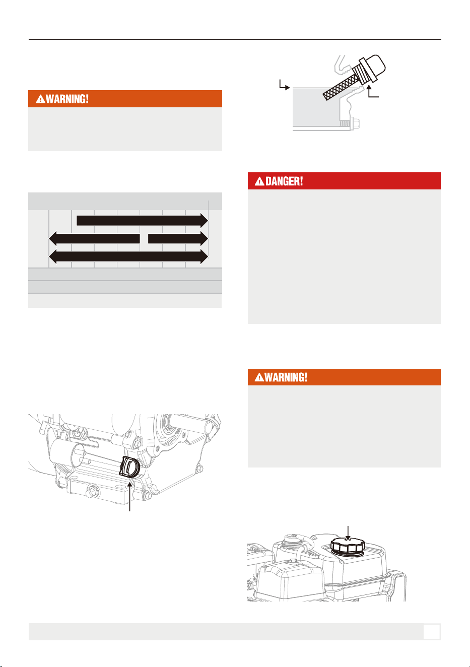
Use SAE 10W-30 4-stroke detergent engine oil
meeting API service classification SJ, SL, or
equivalent.
Use clean, fresh, regular unleaded gasoline with a
minimum octane rating of 87 and an ethanol content
of less than 10% by volume.
Other viscosities shown in the chart may be
used when the average temperature in your
area is within the indicated range.
1. Park the log trailer on a firm, level surface and
shut off the engine before checking or adding engine
oil.
2 .Remove the oil filler cap/dipstick and wipe it
clean.
3. Insert the oil filler cap/dipstick into the oil filler
neck as shown, but do not screw it in. Remove it
again to check the oil level.
4. If the oil level is near or below the lower limit
mark on the dipstick, add engine oil until it reaches
the upper limit mark. Do not overfill.
1. Park the log trailer on a firm, level surface. Shut
off the engine and allow it to cool before refueling.
5. Reinstall the oil filler cap/dipstick securely.
-20 0 20 40 60
Ambient temperature
Recommended Engine Oil Type
80 100
120
-28.9
°
°
F
C -17.8 -6.7 4.4 15.6 26.7 37.8
48.9
10W-30
5W-30 Full Synthetic
10W-405W-30
OIL FILLER CAP/DIPSTICK
UPPER LIMIT
OIL FILLER
CAP/DIPSTICK
FUEL TANK TOP
21
OPERATION
Do not start the engine before adding engine oil.
Never overfill. Check the oil level daily and add
oil as needed.
Do not start the engine before adding fuel.
Gasoline is highly flammable and explosive.
Refueling may cause burns or serious injury if
proper precautions are not followed.
Keep gasoline away from heat, sparks, and open
flames. Refuel only outdoors in a well-ventilated
area. Never refuel indoors.
Do not overfill the fuel tank. If fuel is spilled,
wipe it up immediately before starting the
engine.
Fuel can damage paint and some types of
plastic. Be careful not to spill fuel when filling
your fuel tank.
Never use stale or contaminated gasoline or
oil/gasoline mixture. Avoid getting dirt or water
in the fuel tank.
HYDRAULIC LOG TRAILER WITH CRANE
Add Hydraulic Oil
Start the Engine
(strainer type)
(non-strainer type)
2. Fill the fuel tank below the maximum fuel level
mark.
3. Do not fill the fuel tank completely. Fill the tank to
approximately 25 mm (1 in.) below the top of the
tank to allow room for fuel expansion. Depending on
actual operating conditions, a lower fuel level may
be required. After refueling, tighten the fuel tank cap
securely.
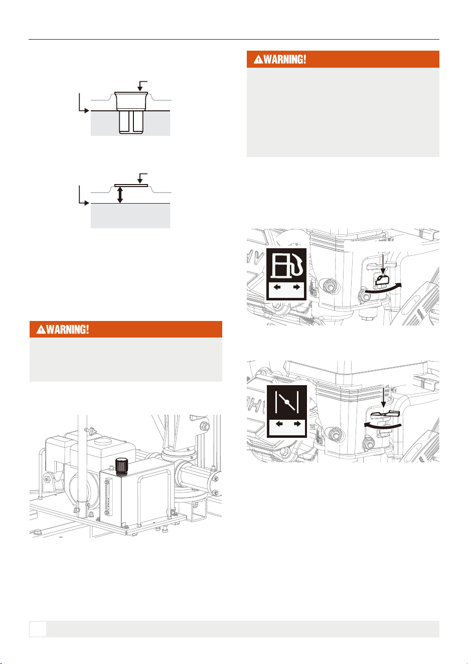
Before operation, fill the hydraulic oil tank with the
recommended hydraulic oil to the proper level. Do
not overfill.
1. Make certain the Log Trailer is on a flat, level
surface.
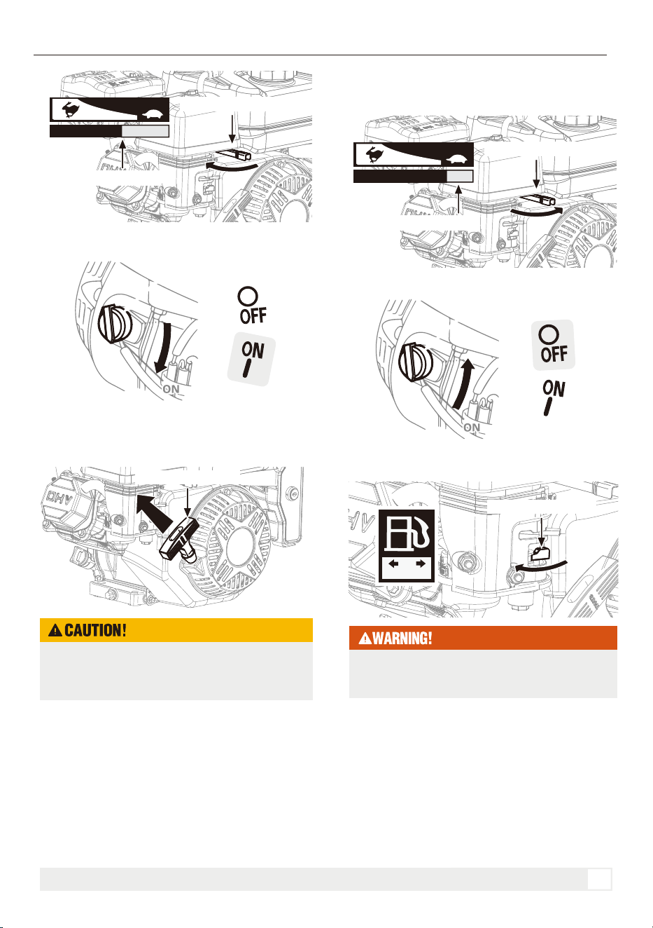
2. Move the fuel valve to the "ON" position.
3.To start a cold engine, move the choke lever to the
"CLOSED" position.
To restart a warm engine, leave the choke lever in
the "OPEN" position.
4. Move the throttle lever away from the MIN.
position, about 1/3 of the way toward the MAX.
position.
MAXIMUM
FUEL LEVEL
FUEL TANK
TOP
MAXIMUM
FUEL LEVEL
FUEL TANK
TOP
25 mm
(1 inch)
FUEL VALVE LEVER
ONOFF
OPENCLOSED
CHOKE LEVER
22
OPERATION
If there is any difference from the actual engine,
refer to the actual engine manual and read the
engine manual carefully before operation.
The hydraulic system may contain air before
initial start-up. During the first operation,
hydraulic oil circulates through the system and
the oil level may drop. After the first use, check
the hydraulic oil level and add oil as needed.
Ensure all hydraulic hoses and fittings are
properly secured before operation.
Applicable hydraulic oil type: ISO VG 46 hydraulic
oil.
HYDRAULIC LOG TRAILER WITH CRANE
Stopping the Engine
6. Pull the starter grip lightly until you feel resistance,
then pull briskly in the direction of the arrow as
shown below. Return the starter grip gently.
6. Always wear hearing and eye protection, protective
clothing, and proper safety equipment during
operation.
Keep choke lever in "CHOKE” position for 2 pulls of
the recoil starter. After second pull, move choke lever
to the "RUN" position for up to the next 3 pulls of the
recoil starter.
1.Move the throttle lever to the MIN position.
2.Turn the engine switch to the OFF position.
THROTTLE LEVER
MIN. POSITION
MIN.MAX.
RECOIL STARTER
23
OPERATION
Do not allow the starter grip to snap back against
the engine. Return it gently to prevent damage to
the starter.
5. Turn the engine switch to the "ON" position.
THROTTLE LEVER
1/3 POSITION
MIN.MAX.
3.Turn the fuel valve lever to the OFF position.
FUEL VALVE LEVER
ONOFF
Always ensure that the fuel valve is in the "OFF”
position when the engine is not in use.
HYDRAULIC LOG TRAILER WITH CRANE
24
OPERATION
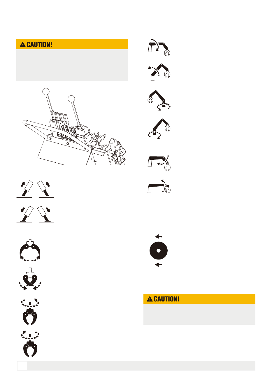
Controls
Pull the lever backward to retract
the stabilizer.
Stabilizer Control
Log Grapple Control
Main boom Control
Hydraulic Winch Controls
Dipper Boom Control
Retract
Push the lever forward to extend
the stabilizer.
Extend
Push the lever forward to open the
grapple.
Open
Pull the lever backward to close the
grapple.
Close
Move the lever to the LH side to
rotate the grapple counterclockwise.
Turn Counterclockwise
Move the lever to the RH side to
rotate the grapple clockwise.
Turn Clockwise
Push the lever forward to lower the
main boom.
Lower
Pull the lever backward to raise the
main boom.
Raise
Push the lever forward to raise the
dipper boom.
Raise
Pull the lever backward to lower the
dipper boom.
Lower
Push and hold the lever forward to
unwind the winch rope.
Release the lever to stop. The lever
automatically returns to the neutral
position.
Unwind
Pull and hold the lever backward to
wind the winch rope onto the drum.
Release the lever to stop. The lever
automatically returns to the neutral
position.
Wind
Move the lever to the LH side to
rotate the main boom counterclock-
wise.
Turn Counterclockwise
Move the lever to the RH side to
rotate the main boom clockwise.
Turn Clockwise
Do not operate the machine until you are
thoroughly familiar with the position and function
of the various controls. Read the operator's
manual thoroughly. Your safety is involved!
LH and RH are viewed from the operator's control
position facing the trailer.
HYDRAULIC LOG TRAILER WITH CRANE
Before starting the log trailer, make sure the machine
is properly connected, stable, and ready for
operation.
1. Park the tow vehicle and log trailer on firm, level
ground whenever possible.
2. Engage the tow vehicle parking brake and secure
the trailer to prevent unintended movement.
3. Inspect the trailer, tires, fasteners, hydraulic hoses,
fittings, grapple, boom, and winch for damage or
excessive wear.
4. Check the engine oil, fuel level, and hydraulic oil
level. Add fluids if necessary.
5. Make sure all hydraulic hoses and connections are
secure and free from leaks.
6. Fully deploy both stabilizer legs before operating
the crane.
7. Make sure the crane boom, grapple, and surround-
ing work area are clear of people and obstacles.
8. Move all hydraulic control levers to the neutral
position.
9. Start the engine according to the engine starting
procedure.
10. Allow the engine to warm up briefly, then operate
each hydraulic function slowly to confirm proper
operation.
11. Check for abnormal noise, vibration, hydraulic
leaks, or erratic movement before beginning work.
Do not operate the log trailer if any damage, leakage,
or unsafe condition is found.
Log Trailer Start-Up
Always operate the Log Trailer outdoors, away
from buildings, windows, and doors. Only trained
adults may operate the log trailer. Keep children
and bystanders away from the operating area.
25
Load the Log Trailer
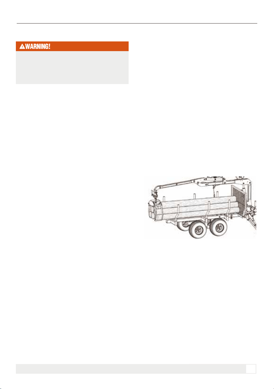
A balanced load is necessary to distribute weight
evenly across the tires and trailer frame. Place
longer, larger-diameter logs on the bottom. Place
shorter, smaller-diameter logs near the top of the
bunk posts.
Before using the grapple, estimate the log's
center of gravity. Grip the log as close as
possible to its center of gravity to keep the load
balanced.
Watch the log continuously while moving the
boom or grapple. Make sure the log does not
contact the machine.
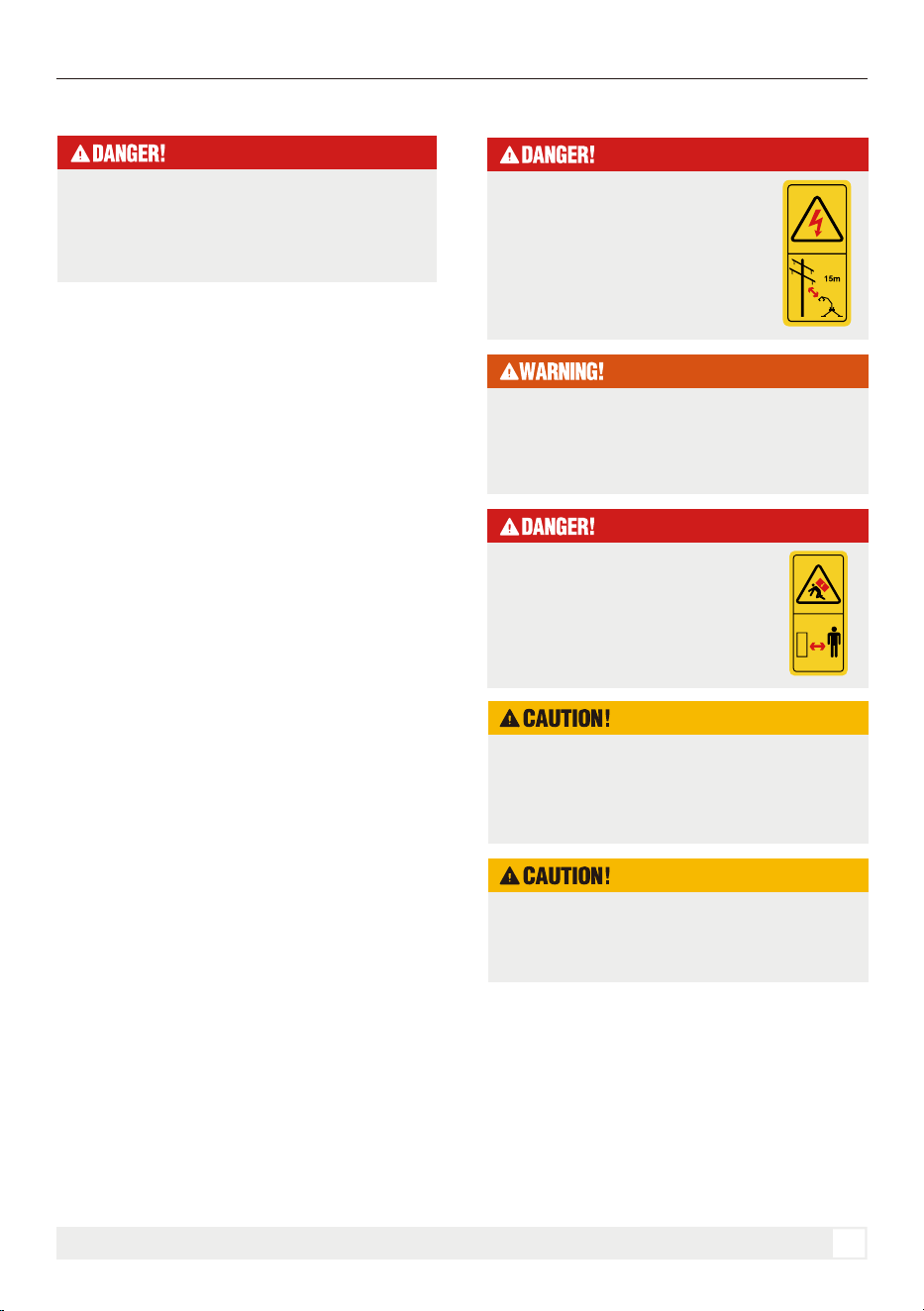
Stay at least 50 ft (15 m) away from
overhead power lines and electrical
cables. Electrocution can occur
without direct contact due to
electrical arcing. Contact with
electricity can cause burns, serious
injury, or death.
Never lift or move loads over people.
Keep all bystanders outside the work
area. A swinging or falling log can
cause serious injury or death.
Always be aware of the position of the boom and
the material being handled. Even with the boom
fully retracted, handling an 8 ft (2.4 m) log may
create a crush or impact hazard for the operator.
OPERATION

HYDRAULIC LOG TRAILER WITH CRANE
Log Loading Safety
Load Procedure
Log Trailer Shutdown
• Do not load logs above the top of the bunk posts.
• Distribute logs evenly across the trailer and keep
the load as low as possible.
• Do not concentrate excessive weight in one area.
• Make sure no logs or branches extend beyond the
sides of the trailer.
• Keep the entire load within the bunk posts.
• Make sure all logs are stable before transport.
• Secure the load with suitable straps before towing.
1. Park on firm, level ground; secure the trailer
against movement; fully deploy both stabilizers on
solid footing; keep bystanders clear; remove the
boom lock pin only after the machine is stable.
2. Raise the boom until the bottom of the grapple is
above the bunk posts.
3. Rotate the boom until the grapple is positioned
above the log's center of gravity.
4. Rotate the grapple until it is perpendicular to the
log.
5. Pick up the log:
a. Open the grapple.
b. Lower the grapple around the log.
c. Close the grapple securely around the log.
d. Slowly raise the boom.
6. Check whether the log is balanced in the grapple:
If the log is balanced, continue to Step 7.
If the log is not balanced:
i. Lower the boom.
ii. Open the grapple.
iii. Reposition the grapple along the log.
iv. Repeat Step 5.
7. Raise the boom until the log is clear of the bunk
posts.
8. Slowly rotate the boom to position the log above
the trailer.
9. Rotate the grapple until the log is parallel with the
trailer.
10. Slowly lower the boom and place the log onto
the trailer.
11. Open the grapple and release the log.
12. Repeat Steps 2–11 until loading is complete.
Make sure the total load does not exceed the
trailer's maximum rated load capacity.
Unload the Log Trailer
1. Set up the machine for operation.
2. If the grapple is closed, open the grapple.
3. Raise the boom until the grapple is above the
trailer bunk posts.
4. Rotate the boom to position the grapple above the
trailer and over the log's center of gravity.
5. Rotate the grapple until it is perpendicular to the
log.
6. Pick up the log:
a. Open the grapple.
b. Lower the grapple around the log.
c. Close the grapple securely around the log.
d. Slowly raise the boom.
7. Check whether the log is balanced in the grapple:
If the log is balanced, continue to Step 8.
If the log is not balanced:
i. Lower the boom.
ii. Open the grapple.
iii. Reposition the grapple along the log.
iv. Repeat Step 6.
8. Raise the boom until the log is clear of the trailer
bunk posts.
9. Slowly rotate the boom to move the log above the
unloading area or log stack. Keep the log clear of the
main boom, cylinders, trailer, and other components.
10. If necessary, rotate the grapple until the log is
aligned with the stack.
11. Slowly lower the boom and place the log on the
ground or stack.
12. Open the grapple and release the log.
13. Repeat Steps 3–12 until the trailer is empty.
26
OPERATION
Follow the steps below to safely shut down the log
trailer after operation:
1. Finish all lifting operations and make sure no load
remains suspended from the grapple.
2. Lower and secure the crane boom and grapple in
the transport position.

HYDRAULIC LOG TRAILER WITH CRANE
27
3. Move all hydraulic control levers to the neutral
position.
4. Allow the engine to idle briefly before shutting it
down.
5. Stop the engine according to the engine shutdown
procedure.
6. Move the hydraulic control levers through all
positions to relieve residual hydraulic pressure.
7. Retract and secure both stabilizer legs only after
the crane is fully stowed.
8. Inspect the machine for hydraulic leaks, damage,
or loose components.
9. Remove debris from the trailer and clean the
machine as necessary.
10. Park the trailer on firm, level ground and secure
it against unintended movement.
Do not leave the machine unattended with the
engine running or with a load suspended.
OPERATION
HYDRAULIC LOG TRAILER WITH CRANE
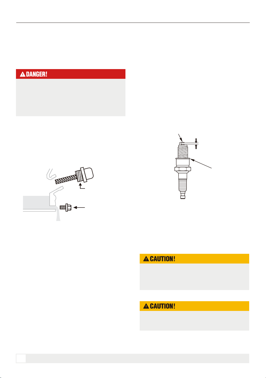
9. Attach the spark plug cap to the spark plug.
A loose spark plug can overheat and damage the
engine. Overtightening the spark plug can
damage the threads in the cylinder head.
When replacing the spark plug, refer to the
engine manual for the correct spark plug type.
28
MAINTENANCE
Regular maintenance helps ensure reliable
performance and long service life. Follow this
manual and the engine manufacturer's owner's
manual for maintenance procedures.
Drain the used oil when the engine is warm. Warm
oil drains quickly and completely.
1. Place a suitable container below the engine to
catch the used oil, then remove the oil filler
cap/dipstick, oil drain plug and washer.
2. Allow the used oil to drain completely, then
reinstall the oil drain plug and new washer, and
tighten the oil drain plug securely.
Please dispose of used motor oil in a manner that is
compatible with the environment. We suggest you
take used oil in a sealed container to your local
recycling center or service station for reclamation.
Do not throw it in the trash, pour it on the ground, or
down a drain.
3. With the engine in a level position, fill to the upper
limit mark (bottom edge of the oil fill hole) on the
dipstick with the recommended oil.
4. Install the oil filler cap/dipstick and tighten
securely.
1. Disconnect the spark plug cap, and remove any
dirt from around the spark plug area.
2. Remove the spark plug with a spark plug wrench.
3. Inspect the spark plug. Replace it if damaged,
badly fouled, if the sealing washer is in poor
condition, or if the electrode is worn.
4. Measure the spark plug electrode gap with a
wire-type feeler gauge. Correct the gap, if necessary,
by carefully bending the side electrode. The gap
should be:0.024-0.031 in (0.6-0.8 mm)
5. Install the spark plug carefully, by hand, to avoid
cross-threading.
6. After the spark plug is seated, tighten with a spark
plug wrench to compress the sealing washer.
7. When installing a new spark plug, tighten 1/2 turn
after the spark plug seats to compress the washer.
8. When reinstalling the original spark plug, tighten
1/8 -1/4 turn after the spark plug seats to compress
the washer.
MAINTENANCE
Changing The Engine Oil
Spark Plug
Shut down the engine, wait for all moving parts
to come to a complete stop, remove the spark
plug wire, and then wait five minutes before
performing maintenance on the log trailer or
engine.
OIL FILLER
CAP/ DIPSTICK
DRAIN PLUG
SEALING
WASHER
SIDEELECTRODE
0.024-0.031 in
(0.6-0.8 mm)
HYDRAULIC LOG TRAILER WITH CRANE
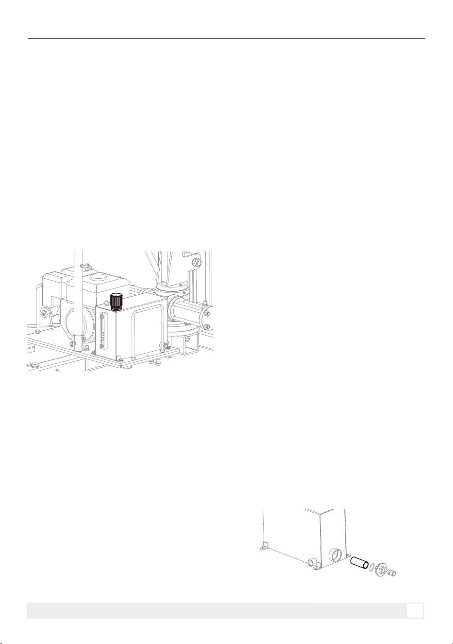
The hydraulic oil tank is located beside the trailer
tongue, opposite the engine. The tank is equipped
with an oil level indicator cap and dipstick for
checking the hydraulic oil level. Check the hydraulic
oil level daily and inspect the oil condition every 50
operating hours. Replace the hydraulic oil if it
becomes contaminated or develops a burnt odor.
1. Allow the engine to cool.
2. Clean the area around the hydraulic oil tank cap
and remove the cap.
3. Using a clean funnel, add hydraulic oil according
to the oil level indicator. Do not fill above the MAX
line on the indicator. Never operate the machine if
the oil level is below the MIN line.
4. Reinstall and tighten the oil tank cap securely.
Wipe up any spilled hydraulic oil.
Applicable hydraulic oil type: ISO VG 46 hydraulic
oil.
The hydraulic oil tank may need to be drained
periodically. The drain plug is located at the bottom
of the tank. Follow the steps below to drain and
replace the hydraulic oil:
1. Allow the machine to cool before changing the
hydraulic oil. Hot oil can cause serious burns if it
comes into contact with exposed skin. For best
results, drain the oil while it is still warm so
contaminants remain suspended in the oil.
2. Place a suitable drain pan under the drain port.
Clean the area around the drain plug, then remove
the plug.
3. Allow the hydraulic oil to drain completely. Flush
the hydraulic tank if necessary.
4. Reinstall and securely tighten the drain plug.
5. Refill the hydraulic tank with the specified
hydraulic oil to the proper level.
6. Operate the hydraulic system briefly to circulate
the oil and purge trapped air. Shut down the
machine, recheck the oil level, and add oil if
necessary.
7. Check the drain plug and hydraulic connections
for leaks.
8. Dispose of used hydraulic oil in accordance with
local environmental regulations.
Replace the hydraulic filter periodically or whenever
it becomes clogged or damaged. Always use a filter
that meets the manufacturer's specifications.
1. Park the machine on a level surface, shut off the
engine, and allow the hydraulic system to cool.
2. Move the hydraulic control levers through all
positions to relieve residual system pressure.
3. Clean the area around the hydraulic filter to
prevent dirt from entering the system.
4. Place a suitable container beneath the filter to
catch any spilled hydraulic oil.
5. Remove the old hydraulic filter.
6. Apply a thin coat of clean hydraulic oil to the seal
of the new filter.
7. Install the new filter and tighten it securely
according to the filter manufacturer's instructions.
Do not overtighten.
8. Check the hydraulic oil level and add the specified
hydraulic oil if necessary.
9. Start the engine and operate the hydraulic
controls briefly to circulate the oil and purge trapped
air.
10. Shut off the engine, check the filter area for
leaks, and recheck the hydraulic oil level.
11. Dispose of the used filter and hydraulic oil in
accordance with local environmental regulations.
29
MAINTENANCE
Add Hydraulic Oil
Hydraulic Filter Replacement
Hydraulic Oil Drain
HYDRAULIC LOG TRAILER WITH CRANE
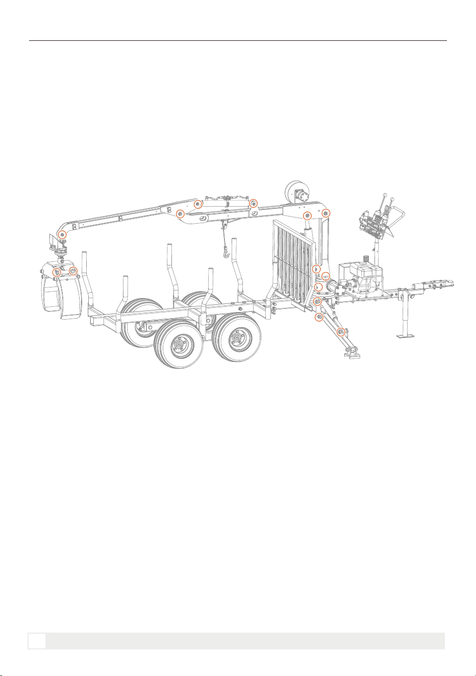
Greasing
Use a hand-operated grease gun for all lubrication.
Before greasing, wipe each grease fitting with a clean cloth to prevent dirt and debris from entering.
Replace or repair damaged fittings immediately.
If a fitting does not accept grease, remove it and clean it thoroughly. Also clean the grease passage. Replace the
fitting if necessary.
The illustration shows the approximate locations of all lubrication points on LT4400/8800 models.
30
MAINTENANCE

HYDRAULIC LOG TRAILER WITH CRANE
Maintenance Schedule
8 HOURS
OR DAILY
PROCEDURE
25 HOURS OR
ANNUALLY
100 HOURS OR
ANNUALLY
ANNUALLY
Check the hydraulic hoses and fittings.
Check the hydraulic fluid level.
Check the engine oil level and quality.
Check the engine fuel level.
Clean around the muffler and controls.
Clean the engine air-intake grille.
Check fasteners and wheel lug nut torque.
Grease the machine.
Check the hydraulic fluid quality.
Repack the axle bearings.
Check the tire pressure.
Change the hydraulic fluid and filter.
Clean the machine.
Service the engine exhaust system.
Clean the engine air filter.
Change the engine oil.
Replace the engine spark plug.
Service the engine cooling system.
Service the engine fuel system.
Replace the engine air filter.
31
MAINTENANCE

HYDRAULIC LOG TRAILER WITH CRANE
32
MAINTENANCE
Please follow the table below to identify the torque value as required.
Tightening Torque
Torque tolerance +0%,-15% of torquing values. Unless otherwise specified use torque values listed above.
1
in-tpi = nominal thread diameter in inches-threads per
inch
2
N.m= newton-meters
3
ft-lb= foot pounds
4
mm x pitch = nominal thread diameter in millimeters x
thread pitch
TORQUE VALUES CHART FOR COMMON BOLT SIZES
Grade 2 Grade 5
Bolt Head Identification Bolt Head Identification
Grade 8 Class 5.8 Class 8.8 Class 10.9
Bolt Size
(Inches)
in-tpi
1
Bolt Size
(Inches)
mm x pitch
4
N.m
2
N.m
ft-lb
3
ft-lb
N.m
ft-lb
N.m
ft-lb
N.m
ft-lb
N.m
ft-lb
1/4"-20
1/4"-28
5/16"-18
5/16"-24
3/8" -16
3/8" -24
7/16" -14
7/16"-20
1/2" -13
1/2" -20
9/16"-12
9/16"-18
5/8" - 11
5/8" -18
3/4" -10
3/4" -16
7/8" -9
7/8" -14
1"-8
1"-12
1-1/8"-7
1-1/8" -12
1-1/4"-7
1-1/4" -12
1-3/8"-6
1-3/8" -12
1-1/2" -6
1-1/2" -12
M5X0.8
M6X1
M8X 1.25
M8X1
M10X 1.5
M10X0.75
M12X 1.75
M12X 1.5
M12X1
M14 X2
M14 X 1.5
M16X2
M16X 1.5
M18 X 2.5
M18 X 1.5
M20 X 2.5
M20 X 1.5
M24X3
M24 X2
M30 X 3.5
M30×2
M36 X3.5
M36X2
4
7
17
18
33
39
58
60
90
92
99
145
155
195
220
280
310
480
525
960
1060
1730
1880
3
5
12
13
25
29
42
44
66
68
73
105
115
145
165
205
230
355
390
705
785
1270
1380
6
11
26
28
52
61
91
95
105
145
155
225
240
310
350
440
650
760
830
1510
1680
2650
2960
5
8
19
21
39
45
67
70
77
105
115
165
180
230
260
325
480
560
610
1120
1240
1950
2190
9
15
36
39
72
85
125
130
145
200
215
315
335
405
485
610
900
1050
1150
2100
2320
3660
4100
7
11
27
29
53
62
93
97
105
150
160
230
245
300
355
450
665
780
845
1550
1710
2700
3220
7.4
8.5
15
17
27
31
43
49
66
75
95
105
130
150
235
260
225
250
340
370
480
540
680
750
890
1010
1180
1330
5.6
6
11
13
20
22
32
36
49
55
70
79
97
110
170
190
165
185
250
275
355
395
500
555
655
745
870
980
11
13
24
26
42
47
67
75
105
115
150
165
205
230
360
405
585
640
875
955
1080
1210
1520
1680
1990
2270
2640
2970
8
10
17
19
31
35
49
55
76
85
110
120
150
170
265
295
430
475
645
705
795
890
1120
1240
1470
1670
1950
2190
16
18
33
37
59
67
95
105
145
165
210
235
285
325
510
570
820
905
1230
1350
1750
1960
2460
2730
3230
3680
4290
4820
12
14
25
27
44
49
70
78
105
120
155
170
210
240
375
420
605
670
910
995
1290
1440
1820
2010
2380
2710
3160
3560
8.85.8 10.9
HYDRAULIC LOG TRAILER WITH CRANE
Transport Safety
Prepare the Machine for Transport
Before operating or towing the machine on a public
roadway, make sure all required lights, reflectors,
warning devices, and markings are installed, clearly
visible, and in proper working condition.
Requirements may vary by location. Contact your
local transportation authority for specific legal
requirements.
Make sure the machine is securely attached to the
tow vehicle and that the hitch pin is properly secured
with a retaining clip.
Always connect the safety chains between the
machine and the tow vehicle before transport.
Never allow passengers to ride on the machine.
Plan your route in advance and avoid heavy traffic
whenever possible.
Do not transport or move the machine while the
engine is running.
Inspect the wheel rims for cracks, dents, or other
damage. Tighten all wheel lug nuts to the specified
torque.
Inspect the tires for cuts, punctures, excessive wear,
or other damage.
Make sure all tires are inflated to the recommended
pressure.
Use a hitch ball that matches the coupler size and
has a rated capacity equal to or greater than the
loaded trailer weight.
Make sure all guards, shields, and covers are
properly installed and securely closed before
transport.
Make sure the engine fuel cap, engine oil cap, and
hydraulic oil reservoir cap are properly installed and
tightened to prevent leakage during transport.
Remove all loose debris and materials from the
machine before transport.
Lower the boom into the transport position and
secure the grapple to prevent movement during
transport.
Make sure the total load does not exceed the
maximum rated load capacity of the machine.
Do not exceed the maximum transport speed of 50
mph (80 km/h). Reduce speed when traveling over
rough terrain or when turning.
1. If the winch accessory is installed:
a. Remove the winch rope and strap from the log.
b. Retract the winch rope fully into the winch.
c. Secure the winch hook to the machine to prevent
movement during transport.
2. Move the log grapple to transport positions:
If logs are loaded, securely grip the end of a log at
the rear of the machine.
3. Install the boom lock pin.
4. Retract and secure both stabilizers:
a. Use the LH or RH stabilizer control lever to fully
retract each stabilizer.
b. Engage the latch bar to lock each stabilizer in
position.
5. Stop the machine.
6. Operate each hydraulic control lever to relieve
residual hydraulic pressure.
Attach the machine securely to the tow vehicle.
33
TRANSPORT
TRANSPORT
Equipment transported on public roads must
comply with all applicable local laws and
regulations governing the safe transport of
machinery.

HYDRAULIC LOG TRAILER WITH CRANE
Attach to a Tow Vehicle
Position the tow vehicle so the hitch ball is directly
below the trailer coupler. Lower the coupler onto the
hitch ball until it is fully seated, then close and lock
the coupler latch. Install the safety pin or locking
device to prevent accidental release. Attach the
safety chains securely to the tow vehicle, crossing
them under the trailer tongue if required. Connect
the trailer electrical plug, if equipped, and verify that
all lights operate properly. Raise and secure the
trailer jack before towing. Finally, check that the
coupler, safety chains, and all connections are
secure before transport.
Trailer Jack
Lower the Trailer Jack
Before removing the jack pin, securely attach the
machine to the tow vehicle or support the trailer
tongue with suitable blocks.
The trailer jack supports the front of the machine
when it is not connected to a tow vehicle and helps
stabilize the machine during coupling or uncoupling.
1. Pull the retaining pin out of the jack mounting
bracket.
2. Rotate the trailer jack to the vertical position.
3. Reinsert the retaining pin through the bracket to
lock the jack in position.
4. Turn the jack handle clockwise to lower the jack
foot until it firmly contacts the ground.
Stow the Trailer Jack
1. Support the machine to remove all weight from
the trailer jack. Attach the machine securely to the
tow vehicle or support the trailer tongue with
suitable blocks.
2. Turn the jack handle counterclockwise to fully
raise the jack foot.
3. Pull the retaining pin out of the jack mounting
bracket.
4. Rotate the trailer jack to the horizontal storage
position.
5. Reinsert the retaining pin through the bracket to
lock the jack securely in the stowed position.
34
TRANSPORT
Do not remove the trailer jack pin while the jack
is supporting the weight of the machine. The
machine may move unexpectedly and cause
injury.

HYDRAULIC LOG TRAILER WITH CRANE
Storage Safety
At the end of the operating season, or whenever the
machine will not be used for an extended period,
thoroughly inspect all major systems and compo-
nents. Repair or replace any worn or damaged parts
to help prevent downtime when the machine is
returned to service.
Clean the machine thoroughly and touch up any
scratched or damaged painted surfaces to help
prevent corrosion.
• Store the machine in a dry, level, and secure
location away from unauthorized persons and
general activity.
• Store the machine indoors whenever possible.
• Support the main frame securely with suitable
blocks if necessary.
• Make sure the machine is stable and cannot roll,
shift, or tip during storage.
• Keep the storage area clean and free of flammable
materials.
35
STORAGE
STORAGE
Do not allow children to play on, near, or around
the stored machine. Serious injury or death may
result.
Do not use a pressure washer directly on the
product identification plate. High-pressure water
may damage the plate or make the information
unreadable. Clean the plate with a soft cloth
dampened with water.

HYDRAULIC LOG TRAILER WITH CRANE
TROUBLESHOOTING
RECOMMENDED SOLUTION
PROBLEM
POSSIBLE CAUSE
The hydraulic system is not
building sufficient pressure.
The grapple hydraulic hoses are
connected incorrectly.
The engine speed is too low.
The valve spool return spring or
valve spool is faulty.
The hydraulic system is not
building sufficient pressure.
The hydraulic control valve may be
damaged.
The hose is worn, cracked, or
damaged.
There is air in the hydraulic
system or a hydraulic leak.
The hydraulic cylinder seals are
worn or damaged.
The hydraulic cylinder seals are
leaking.
The hydraulic cylinder counterbal-
ance valve is damaged.
Replace the cylinder seals or the
hydraulic cylinder as required.
Have the counterbalance valve
inspected and replaced if
necessary.
Replace the cylinder seals or the
hydraulic cylinder as required.
Check the hydraulic oil level and refill
if necessary. Replace the hydraulic oil
filter if it is restricted or due for
service.
Check the hydraulic hose connections
and match the color-coded couplers
correctly.
Set the throttle to the normal
operating position specified in the
engine manual.
Replace the return spring, valve spool,
or control valve as required.
Check the hydraulic oil level and
hydraulic oil filter. Refill or replace
components as necessary.
Have the hydraulic control valve
inspected and repaired or replaced by
a qualified service technician.
Replace the damaged hydraulic hose.
Inspect the hydraulic system for leaks
and tighten all hose and fitting
connections securely.
36
Hydraulic cylinders move
slowly or do not move (main
boom, dipper boom, grapple,
or stabilizers).
Hydraulic control lever does
not return to neutral when
released.
Hydraulic hose leaks.
Main boom or dipper boom
slowly drifts downward.
Hydraulic cylinder leaks.
Hydraulic cylinder movement
is not smooth.
TROUBLESHOOTING

RECOMMENDED SOLUTION
PROBLEM
POSSIBLE CAUSE
The boom lock pin is installed.
The hydraulic system is not
building sufficient pressure.
The engine speed is too low.
The main boom rotation gears are
jammed.
The main boom rotation sprocket
and gears are not lubricated.
Remove the boom lock pin before
operating the boom.
Check the hydraulic oil level and
hydraulic oil filter. Refill or replace
components as necessary.
Make sure the choke is fully open
after warm-up, then increase the
engine speed to the recommended
operating RPM.
Remove dirt, wood chips, and
other debris from the rotation
gears.
Apply grease to the rotation
sprocket and gears.
HYDRAULIC LOG TRAILER WITH CRANE
Main boom does not rotate
or rotates slowly.
37
TROUBLESHOOTING
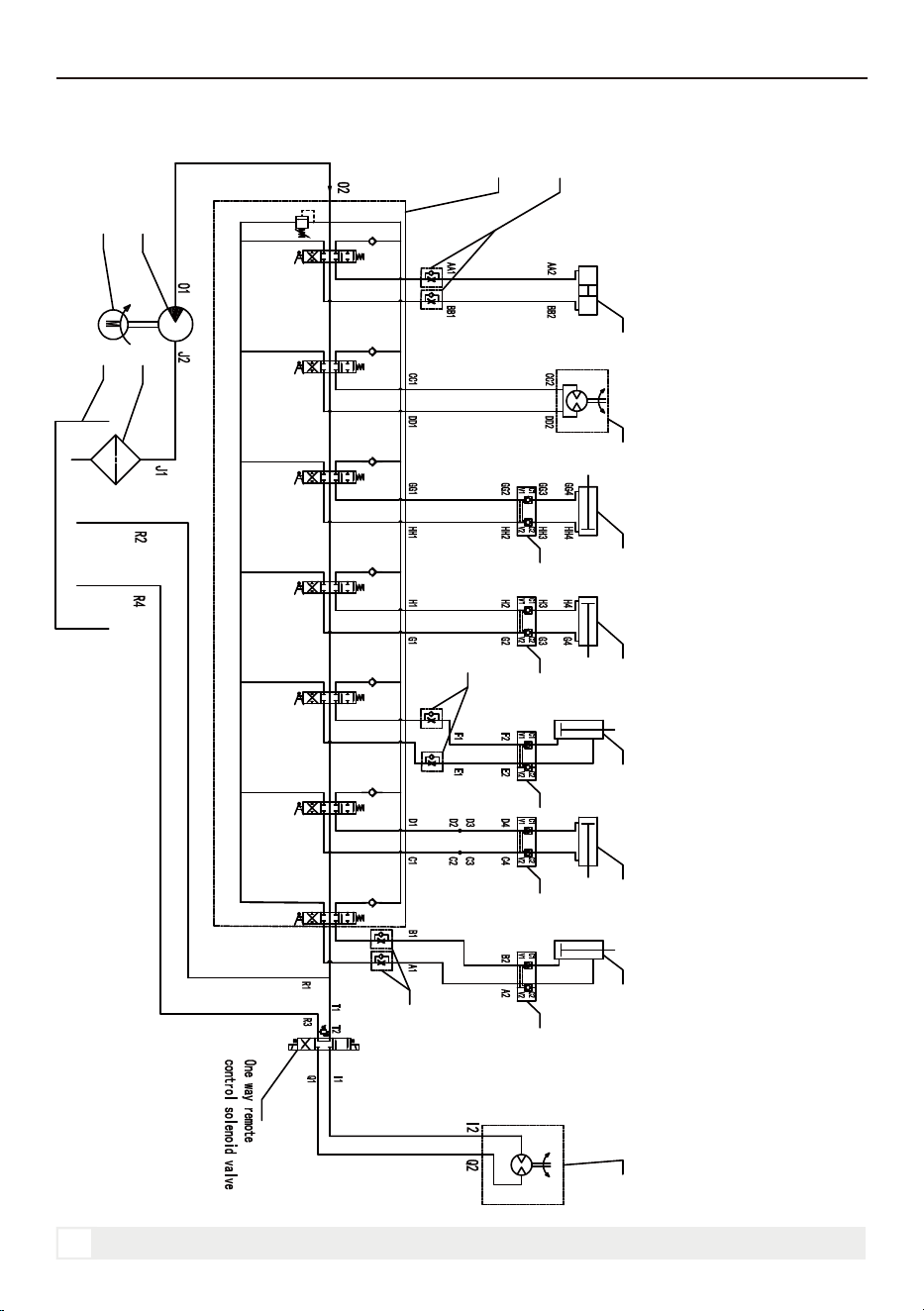
Vertical Boom Cylinder
Grapple Rotator Motor
Left Stabilizer Cylinder
Right Stabilizer Cylinder
Rear Boom Cylinder
Dipper Boom Cylinder
Grapple Cylinder
Hydraulic Winch Motor
HYDRAULIC LOG TRAILER WITH CRANE
HYDRAULIC SYSTEM DIAGRAM
P
T
11
10
98765421
11
17
11
12
15
14
16
13
12 12 12 12
38
HYDRAULIC SYSTEM DIAGRAM
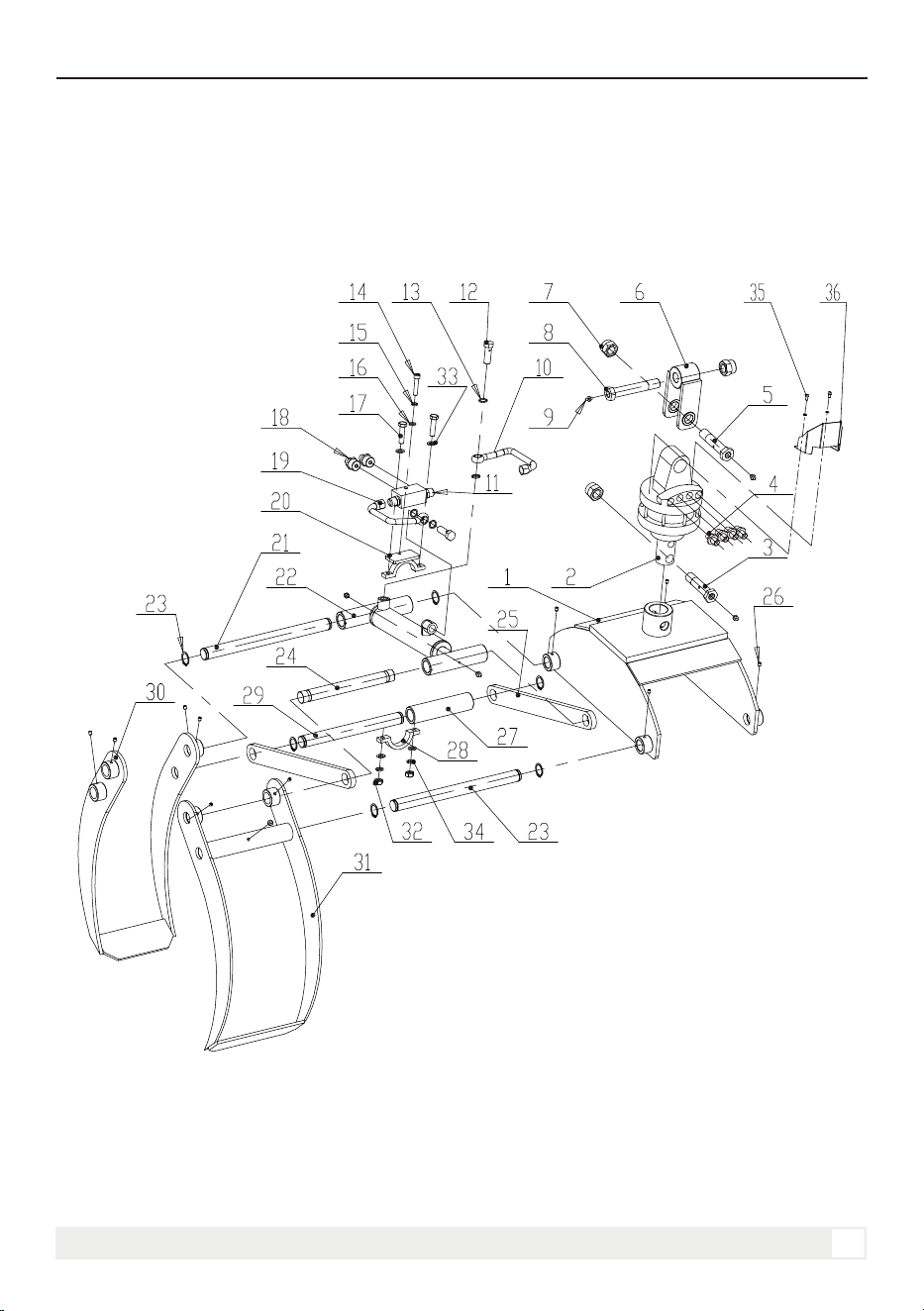
Grapple Assembly
HYDRAULIC LOG TRAILER WITH CRANE
PARTS DIAGRAM
39
PARTS DIAGRAM

Parts List
NO.
DESCRIPTION
QTY.
1
2
3
4
5
6
7
8
9
10
11
12
13
14
15
16
17
18
19
20
21
22
23
24
25
26
27
28
29
30
31
32
33
34
35
36
1
1
1
4
1
1
3
1
6
1
1
2
4
1
3
1
2
2
1
1
2
1
6
1
2
11
1
1
1
1
1
2
4
2
2
1
1.5-2.0 Ton Grapple Base Plate Weldment
Grapple Rotator Motor
3 Ton Grapple Threaded Connecting Shaft
1/4ED-1/4C Hydraulic Fitting
M20 Rotator Motor Mounting Bolt
Rotary Joint Mounting Bracket Weldment
M20 Hex Lock Nut
M20 Front Crossbeam Cylinder Mounting Bolt, 1.5 Ton
M6 x 1 Grease Fitting
50 Grapple Cylinder CE Steel Tube Weldment
LB4 Valve (Hydraulic Lock Valve)
1/4 in. Banjo Bolt
1/4 in. Bonded Seal Washer
M8 x 40 Socket Head Cap Screw
M8 Spring Washer
M8 Flat Washer
M10 x 65 Hex Head Bolt
3/8 in. to 1/4 in. Reducing Nipple
50 Grapple Cylinder CE Steel Tube No. 2 Weldment
50 Grapple Cylinder CE Clamp Plate No. 2 Weldment
Grapple Long Connecting Link
Grapple Cylinder
25 mm External Circlip
Grapple Short Connecting Pin No. 1
Grapple Support Plate
M6 x 6 Hex Socket Cup-Point Set Screw
Grapple Large Spacer
50 Grapple Cylinder CE Clamp Plate No. 1
Grapple Short Connecting Pin
1.5-4 Ton Grapple Jaw No. 1 Weldment
1.5-4 Ton Grapple Jaw No. 2 Weldment
M10 Hex Nut
M10 Flat Washer
M10 Spring Washer
M8 x 25 Socket Head Cap Screw
Rotator Motor Guard Plate
HYDRAULIC LOG TRAILER WITH CRANE
40
PARTS DIAGRAM
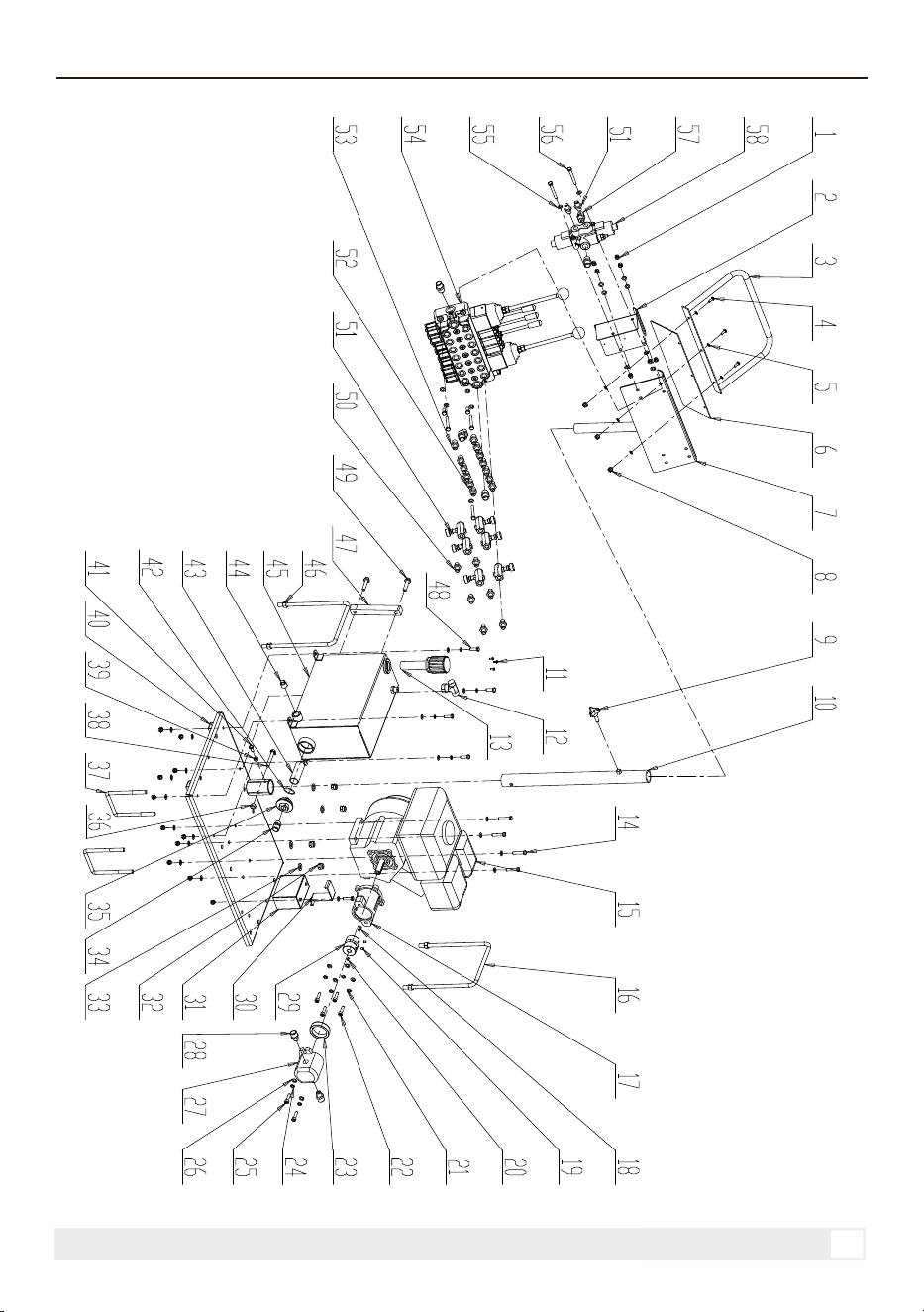
Engine Assembly
HYDRAULIC LOG TRAILER WITH CRANE
41
PARTS DIAGRAM

Parts List
NO.
DESCRIPTION
QTY.
1
2
3
4
5
6
7
8
9
10
11
12
13
14
15
16
17
18
19
20
21
22
23
24
25
26
27
28
29
30
31
32
33
34
35
36
16
1
1
3
6
1
1
3
1
1
3
1
1
4
1
2
1
1
2
1
4
4
1
2
2
2
1
2
1
1
1
8
12
1
1
1
M8 Hex Lock Nut
Single Solenoid Valve Mounting Plate
Handlebar Weldment
M5 x 20 Hex Bolt
M5 Flat Washer
Identification Plate
8-Section Valve Mounting Plate Weldment
M5 Hex Lock Nut
M10 x 40 x 30 Triangular Knob
Directional Valve Support Rod Weldment
M4 x 10 Phillips Pan Head Screw
1/2" Female Tee Fitting
Hydraulic Tank Breather Filler Cap
M8 x 40 Hex Bolt
Engine
Bent Handle for 1.5 Ton Engine Mounting Plate
Hydraulic Pump Mounting Bracket
4.8 x 4.8 Engine Parallel Key
M6 x 8 Hex Socket Cup-Point Set Screw
3.18 x 3.18 Hydraulic Pump Parallel Key
M8 Spring Washer
M8 x 30 Socket Head Cap Screw
Hydraulic Pump Bushing
M10 Spring Washer
M10 x 40 Socket Head Cap Screw
M10 Flat Washer
Gear Pump
M18-M22H Adapter Fitting
XL1 Jaw Coupling
Battery Clamp
12 V 3 Ah Lithium Battery
M12 Hex Lock Nut
M12 Flat Washer
M16-M22H Adapter Fitting
Hydraulic Oil Filter Fitting
M10 Hex Lock Nut
HYDRAULIC LOG TRAILER WITH CRANE
42
PARTS DIAGRAM

NO.
DESCRIPTION
QTY.
37
38
39
40
41
42
43
44
45
46
47
48
49
50
51
52
53
54
55
56
57
58
2
1
1
1
1
1
1
1
1
4
1
5
2
6
6
8
6
1
38
5
5
1
HYDRAULIC LOG TRAILER WITH CRANE
Base Plate Mounting Bolt
M10 x 65 Hex Bolt
M8 Hex Nut
1.5 Ton Engine Mounting Plate
M8 x 20 Hex Bolt
35.5 x 3.55 O-Ring
Hydraulic Suction Filter Element
G3/8 x 19 Drain Plug
1.5 Ton Hydraulic Oil Tank Weldment
M12 Hex Nut
Oil Level Gauge / Sight Glass
M8 x 25 Hex Bolt
Special Mounting Screw
1/4 Taper-1/4C Hydraulic Fitting
1/4" One-Way Flow Control Valve
3/8"-1/4" Reducing Nipple
3/8"-1/4" Taper Adapter
7-Section Directional Control Valve
M8 Flat Washer
M8 x 60 Hex Bolt
1/2" Straight Nipple
Single Solenoid Valve
43
PARTS DIAGRAM
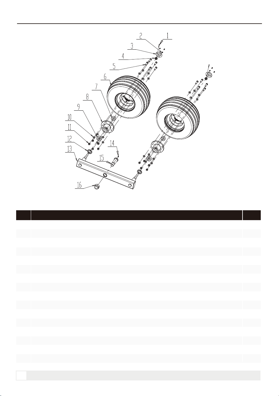
Right Axle Bracket Assembly
Parts List
NO.
DESCRIPTION
QTY.
1
2
3
4
5
6
7
8
9
10
11
12
13
14
15
16
2
6
2
2
10
2
2
2
2
10
10
2
1
2
2
1
4 x 35 Cotter Pin
M6 x 12 Flat Head Hex Bolt
Grapple Wheel Hub Dust Cap
M20 x 1.5 Hex Slotted Nut (29 x 15 mm)
M14 x 45 Flat Head Hex Bolt
Grapple Tire / Wheel Rim, 23-R-4
32304 Tapered Roller Bearing
5-Hole Grapple Wheel Hub
33206 Tapered Roller Bearing
M14 Flat Washer
M14 Hex Lock Nut
62 x 38 x 8 Radial Shaft Oil Seal
3-4 Ton Grapple Axle Connecting Tube Weldment
M6 x 1 Grease Fitting
Grapple Axle Bracket Connecting Shaft
M36 Hex Lock Nut
HYDRAULIC LOG TRAILER WITH CRANE
44
PARTS DIAGRAM
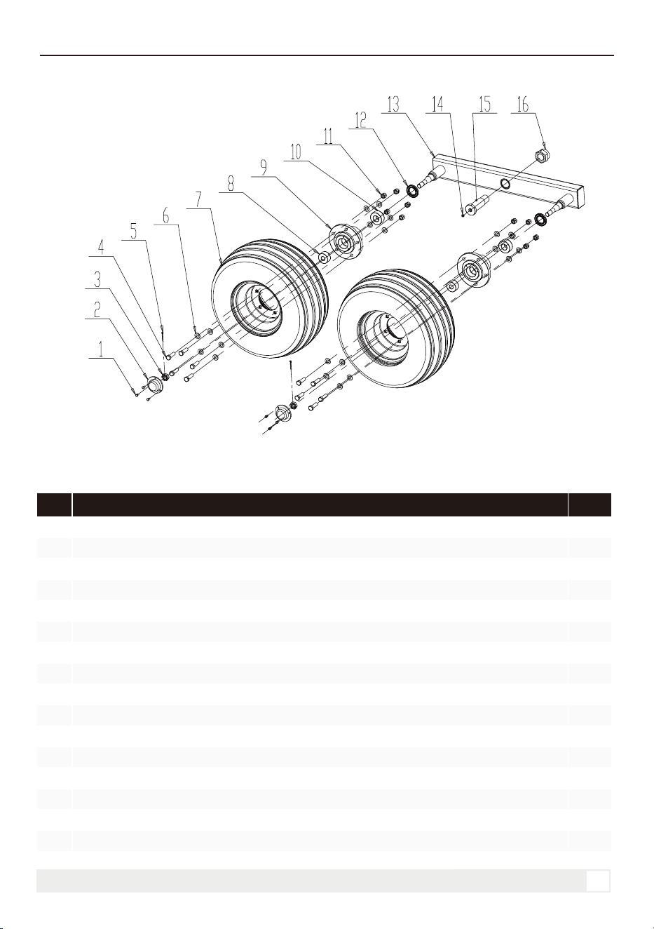
Left Axle Bracket Assembly
Parts List
NO.
DESCRIPTION
QTY.
1
2
3
4
5
6
7
8
9
10
11
12
13
14
15
16
6
2
2
10
2
10
2
2
2
2
10
2
1
2
2
1
M6 x 12 Flat Head Hex Bolt
Grapple Wheel Hub Dust Cap
M20 x 1.5 Hex Slotted Nut (29 x 15 mm)
M14 x 45 Flat Head Hex Bolt
4 x 35 Cotter Pin
M14 Flat Washer
Grapple Tire / Wheel Rim, 23-R-4
32304 Tapered Roller Bearing
5-Hole Grapple Wheel Hub
33206 Tapered Roller Bearing
M14 Hex Lock Nut
62 x 38 x 8 Radial Shaft Oil Seal
3-4 Ton Grapple Axle Connecting Tube Weldment
M6 x 1 Grease Fitting
Grapple Axle Bracket Connecting Shaft
M36 Hex Lock Nut
HYDRAULIC LOG TRAILER WITH CRANE
45
PARTS DIAGRAM
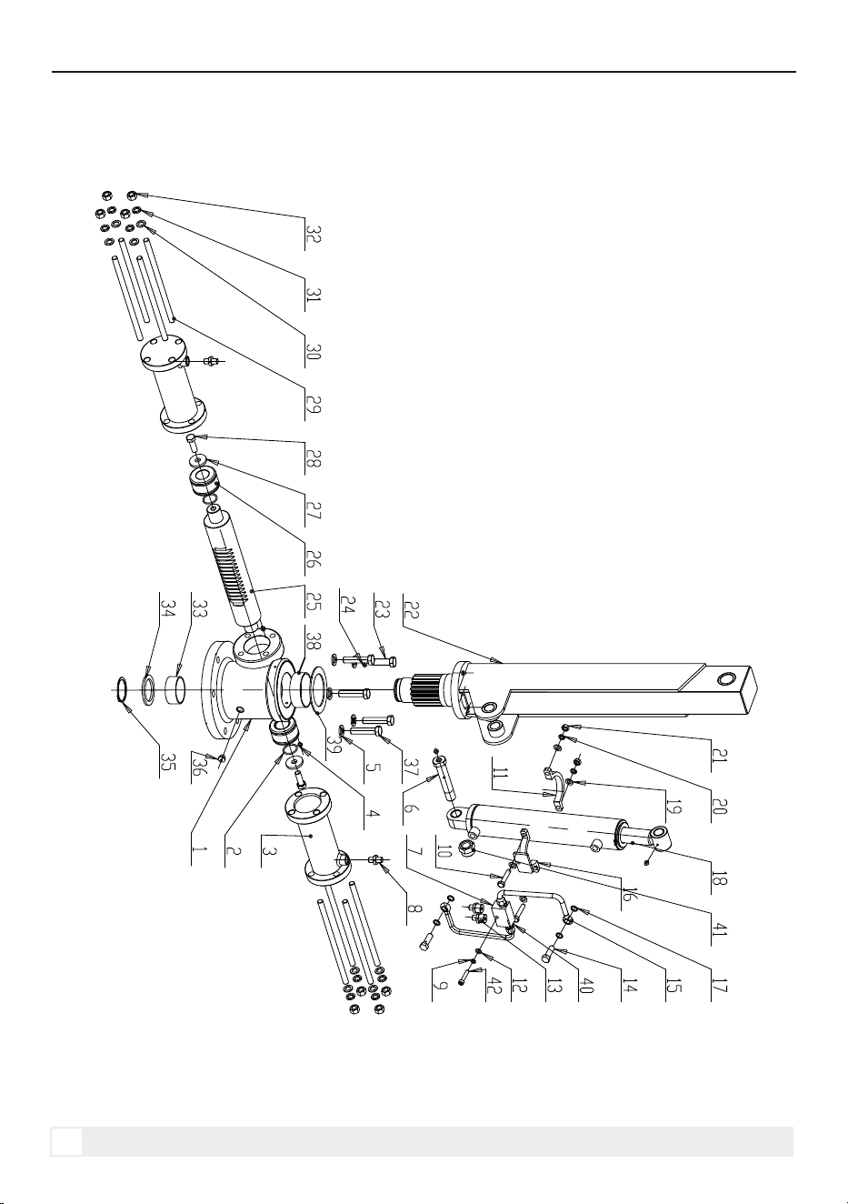
Vertical Boom Assembly
HYDRAULIC LOG TRAILER WITH CRANE
46
PARTS DIAGRAM

Parts List
NO.
DESCRIPTION
QTY.
1
2
3
4
5
6
7
8
9
10
11
12
13
14
15
16
17
18
19
20
21
22
23
24
25
26
27
28
29
30
31
32
33
34
35
36
1
2
2
5
5
1
1
2
1
2
1
1
2
2
2
1
4
1
4
2
2
1
1
1
1
2
2
2
8
8
8
8
1
1
1
1
4 Ton Grapple Crane Slewing Base
35.5 x 3.55 O-Ring
Slewing Cylinder
M6 x 1 Grease Fitting
M16 Flat Washer
4 Ton Crane Rear Boom Threaded Pin, L=120 mm
Hydraulic Lock Valve
1/4ED-1/4C Hydraulic Fitting
M8 Spring Washer
M10 x 50 Hex Head Bolt
80 Upright Boom Cylinder CE Clamp Plate No. 1
M8 Flat Washer
3/8-1/4 Reducing Nipple
1/4 in. Banjo Bolt
80 Upright Boom Cylinder CE Steel Tube No. 2 Weldment
80 Upright Boom Cylinder CE Clamp Plate No. 2 Weldment
1/4 in. Bonded Seal Washer
Main Boom Cylinder
M10 Flat Washer
M10 Spring Washer
M10 Hex Nut
1.5-2.0 Ton Grapple Crane Upright Beam Weldment
M16 x 50 Hex Head Bolt
M16 Spring Washer
3 Ton Grapple Crane Gear Rack
Slewing Cylinder Piston
Gear Rack Shaft Piston Washer
M14 x 30 Flat Head Hex Bolt (Grade 8.8)
M14 x 290 Double-End Stud Bolt
M14 Flat Washer
M14 Spring Washer
M14 Hex Nut
Bearing Housing Plain Bearing 70 x 65
Large Washer, dia. 59 x 80
External Circlip, dia. 60
M14 x 1.5 Grease Fitting
HYDRAULIC LOG TRAILER WITH CRANE
47
PARTS DIAGRAM
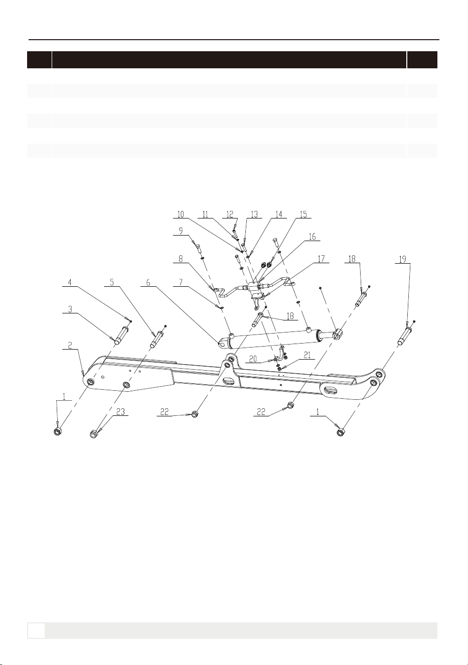
Rear Boom Assembly
HYDRAULIC LOG TRAILER WITH CRANE
NO.
DESCRIPTION
QTY.
37
38
39
40
41
42
M16 x 70 Hex Head Bolt
Bearing Housing Plain Bearing 90 x 85
Bearing Housing Thrust Plain Bearing
M18 Swivel Nut - M14H Fitting
M24 Hex Lock Nut
M8 x 40 Socket Head Cap Screw
4
1
1
2
1
1
48
PARTS DIAGRAM

49
PARTS DIAGRAM
Parts List
NO.
DESCRIPTION
QTY.
1
2
3
4
5
6
7
8
9
10
11
12
13
14
15
16
17
18
19
20
21
22
23
2
1
2
6
1
1
4
2
2
1
1
1
2
4
2
1
1
2
1
1
2
2
1
M27 Hex Lock Nut
1.5 Ton Non-Telescopic Rear Crossbeam Weldment
M27 Rear Crossbeam Threaded Pin, 1.5 Ton
M6 x 1 Grease Fitting
M24 Main Boom Cylinder Upper Mounting Bolt
Rear Boom Cylinder (Jib Arm)
1/4" Bonded Seal Washer
70 Cylinder Steel Tube Weldment with Hydraulic Lock
1/4" Banjo Bolt
M8 Flat Washer
M8 Spring Washer
M8 x 40 Socket Head Cap Screw
M10 x 40 Hex Bolt
M10 Flat Washer
3/8"-1/4" Reducing Nipple
LB4 Valve (Hydraulic Lock Valve)
70 Rear Boom Cylinder Hydraulic Lock Weldment
M20 Front Crossbeam Cylinder Mounting Pin, 1.5 Ton
M27 Front Crossbeam Threaded Pin, 1.5 Ton
70 Rear Boom Cylinder CE Clamp Plate No. 1
M10 Hex Lock Nut
M20 Hex Lock Nut
M24 Hex Lock Nut
HYDRAULIC LOG TRAILER WITH CRANE
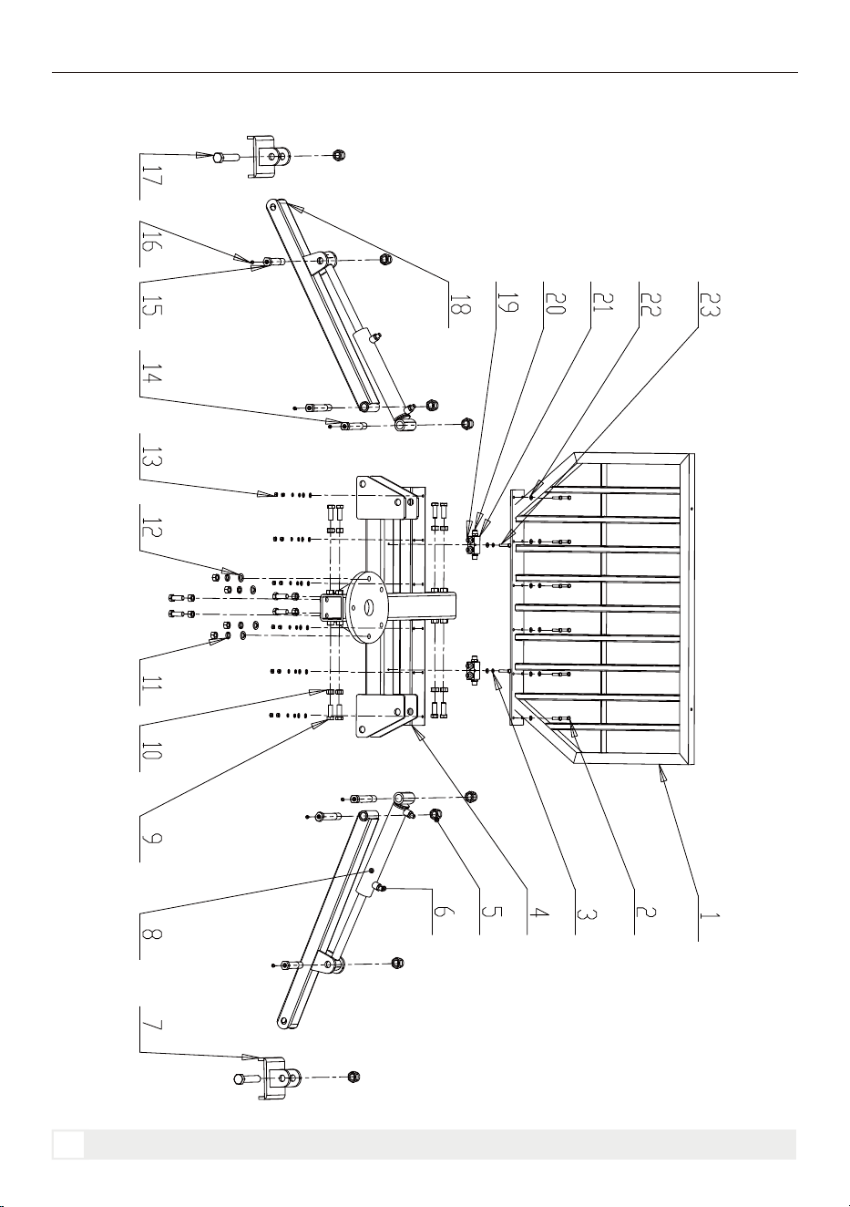
HYDRAULIC LOG TRAILER WITH CRANE
Front Frame Guard Assembly
50
PARTS DIAGRAM

HYDRAULIC LOG TRAILER WITH CRANE
Parts List
NO.
DESCRIPTION
QTY.
1
2
3
4
5
6
7
8
9
10
11
12
13
14
15
16
17
18
19
20
21
22
23
1
12
14
1
8
4
2
2
12
16
4
4
12
4
2
6
2
2
4
2
2
26
2
Grapple Large Mesh Weldment
M8 x 30 Hex Head Bolt
M8 Spring Washer
4 Ton Grapple Front Frame Weldment
M24 Hex Lock Nut
1/4ED-1/4C Hydraulic Fitting
Grapple Base Plate Weldment
Outrigger Cylinder
M16 x 45 Hex Head Bolt
M16 Hex Nut
M16 Spring Washer
M16 Flat Washer
M8 Hex Nut
4 Ton Crane Rear Boom Threaded Shaft, L=130 mm
4 Ton Crane Outrigger Cylinder Lower Threaded Shaft
M6 x 1 Grease Fitting
M24 x 120 Hex Head Bolt
New Outrigger Assembly Weldment
3/8-1/4 Reducing Nipple
M18 Swivel Nut-M14H Fitting
LB4 Valve (Hydraulic Lock Valve)
M8 Flat Washer
M8 x 40 Hex Head Bolt
51
PARTS DIAGRAM
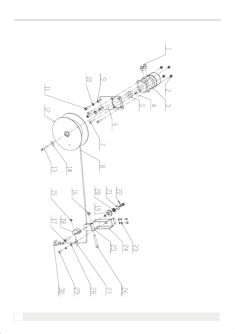
HYDRAULIC LOG TRAILER WITH CRANE
Winch Assembly
52
PARTS DIAGRAM

Parts List
NO.
DESCRIPTION
QTY.
1
2
3
4
5
6
7
8
9
10
11
12
13
14
15
16
17
18
19
20
21
22
23
24
25
26
27
28
29
30
2
4
1
1
1
1
4
1
2
2
2
1
1
1
1
2
1
1
1
1
1
2
2
1
1
1
1
3
3
1
M18-1/4 Hydraulic Adapter Fitting
M10 Hex Lock Nut
BM2-160 Hydraulic Motor
8 x 30 Parallel Key
Winch Drum Washer
Hydraulic Motor Mounting Plate
M10 x 45 Hex Socket Countersunk Head Screw
5 mm x 25 m Steel Wire Rope (7x19)
M12 Flat Washer
M12 Spring Washer
M12 x 25 Hex Bolt
Winch Drum Weldment
M8 x 80 Hex Bolt
45 x 5.0 Large Washer
M8 Hex Lock Nut
M12 Hex Lock Nut
M12 x 45 Socket Head Cap Screw
Rope Guide Mount
550 Pulley No. 2
6001-2RS (ZZ) Bearing
28 mm Internal Circlip
550 Spacer No. 2
M8 Spring Washer
Winch Rope Guide Bracket
Guide Pulley Bracket Weldment
M12 x 80 Socket Head Cap Screw
M8 x 16 Eye Bolt
M8 Flat Washer
M8 x 20 Hex Bolt
Hook
HYDRAULIC LOG TRAILER WITH CRANE
53
PARTS DIAGRAM

RELIABLE EFFICIENT VALUE
315-750-4008
Our company is committed to continuous product improvement. The actual
product may differ from the pictures or descriptions in this manual. Specifica-
tions and design are subject to change without prior notice.
www.mechmaxx.com