Amazon ARGUS RFID Reader Datasheet
1. Overview
The Amazon ARGUS is a high-performance, 16-port UHF RFID reader designed for fixed
installaCons requiring fast, reliable EPC-class tag detecCon. ARGUS integrates the Silion SIM7400
RFID module with a custom interface PCB, providing a streamlined soluCon for inventory
tracking, asset monitoring, and real-Cme sensing in enterprise environments.
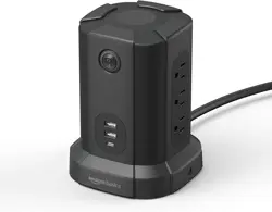
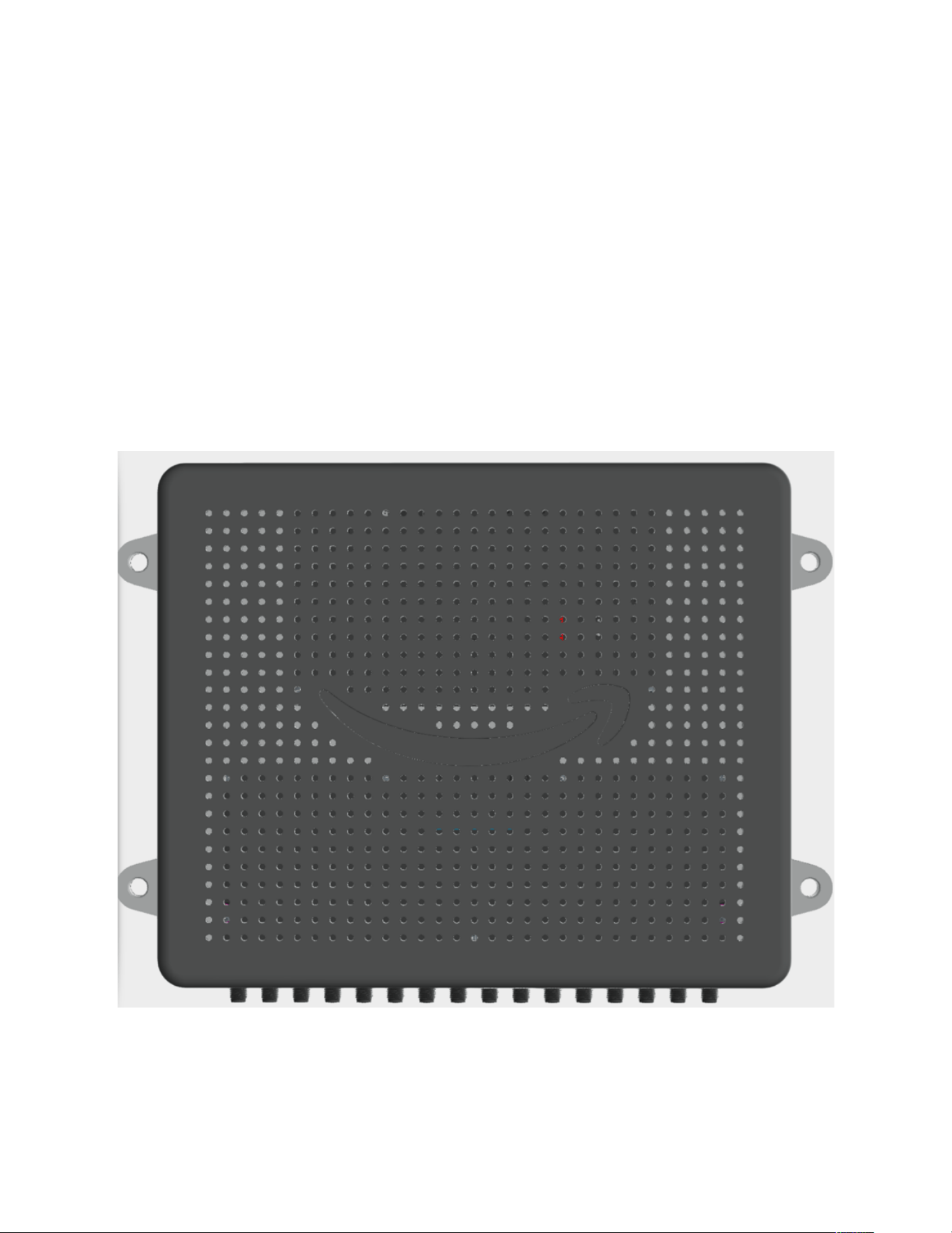
Figure 1 - Amazon ARGUS Assembled Unit
2. System Architecture
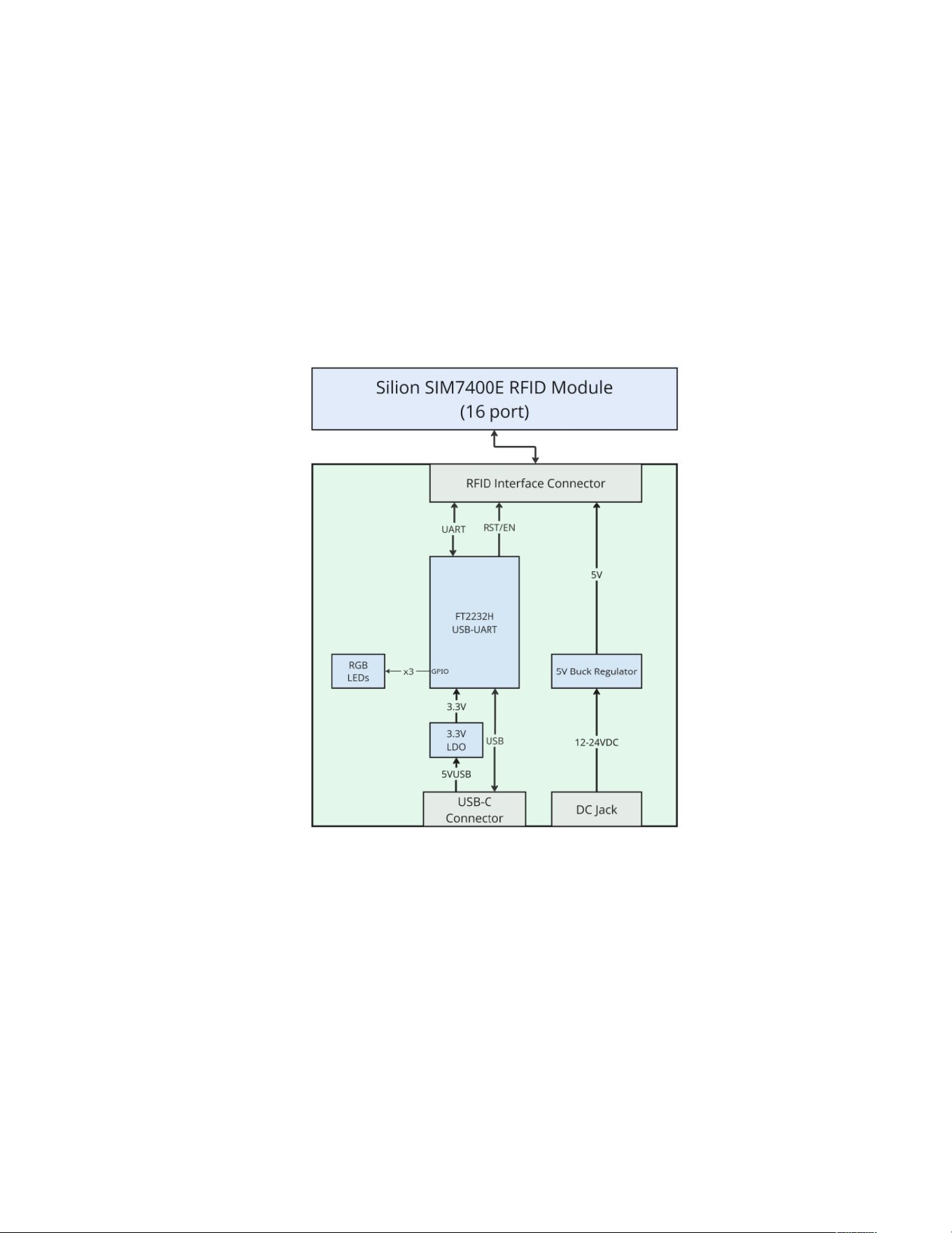
Below is a high-level overview of Amazon ARGUS:
• RFID Module: Silion SIM7400 (Impinj E710-based)
• Interface PCB: USB-UART bridge, power regulation, GPIO control
• External Connectivity: USB-C for data, DC input for power
• Antenna Connectivity: 16 coaxial UHF ports
Figure 2 ARGUS Block Diagram
3. Product Descrip:on
3.1 User Interface
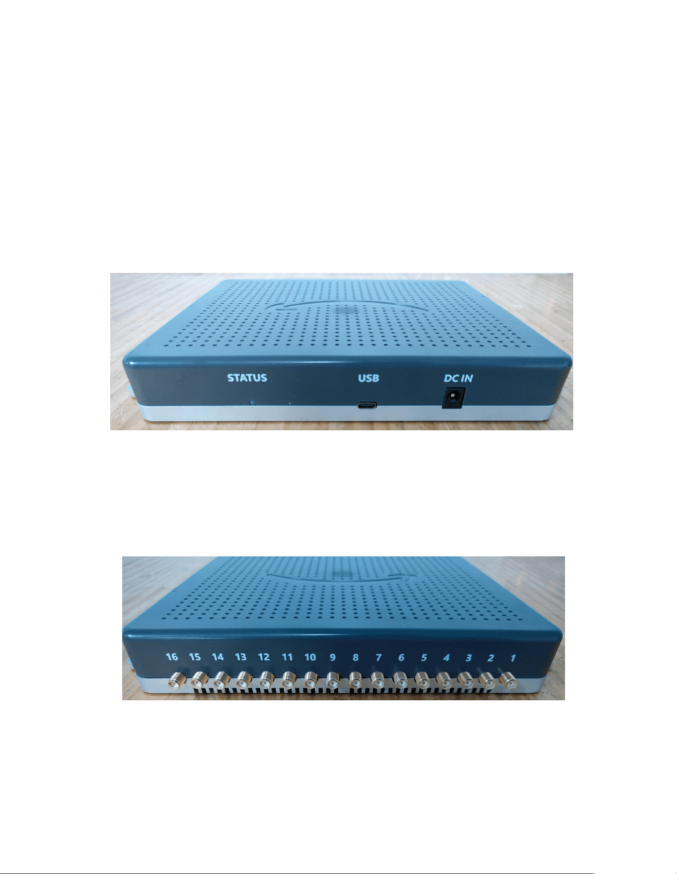
The front interface provides essential connectivity and status indication:
•
Status LED: Fully user-programmable indicator for application states or diagnostics
•
USB-C Connector: Main communication interface to a host PC
•
DC Power Input: External DC supply input for powering the RFID module and internal
electronics
Figure
3
Front User Ports
The rear panel contains:
•
Sixteen (16) UHF Antenna Ports:
Individually addressable ports enabling multi
-
zone
read coverage.
Figure
4
Rear RFID Antenna Ports
3.2 RFID Engine
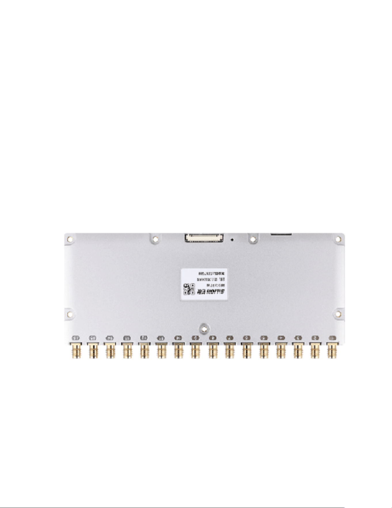
Amazon ARGUS uses the Silion SIM7400 module, a high-performance 16-port UHF reader
module based on the Impinj E710 chipset.
Key capabilities include:
• Protocols Supported: EPC Global Gen2 (ISO 18000-6C)
• Transmit Power: Adjustable from 5 dBm to 30 dBm (±1 dBm)
• Receiver Sensitivity: -86 dBm
• Dense Reader/Anti-Collision Performance: Optimized for high-tag-count environments
• Real-Time Telemetry: Temperature, RSSI, antenna detection, and other diagnostics
These characteristics make the module suitable for deployments requiring:
• Multi-antenna scanning
• High-rate tag inventory
• Reliable read performance across varying RF conditions
Figure 5 Silion SIM7400 RFID Module
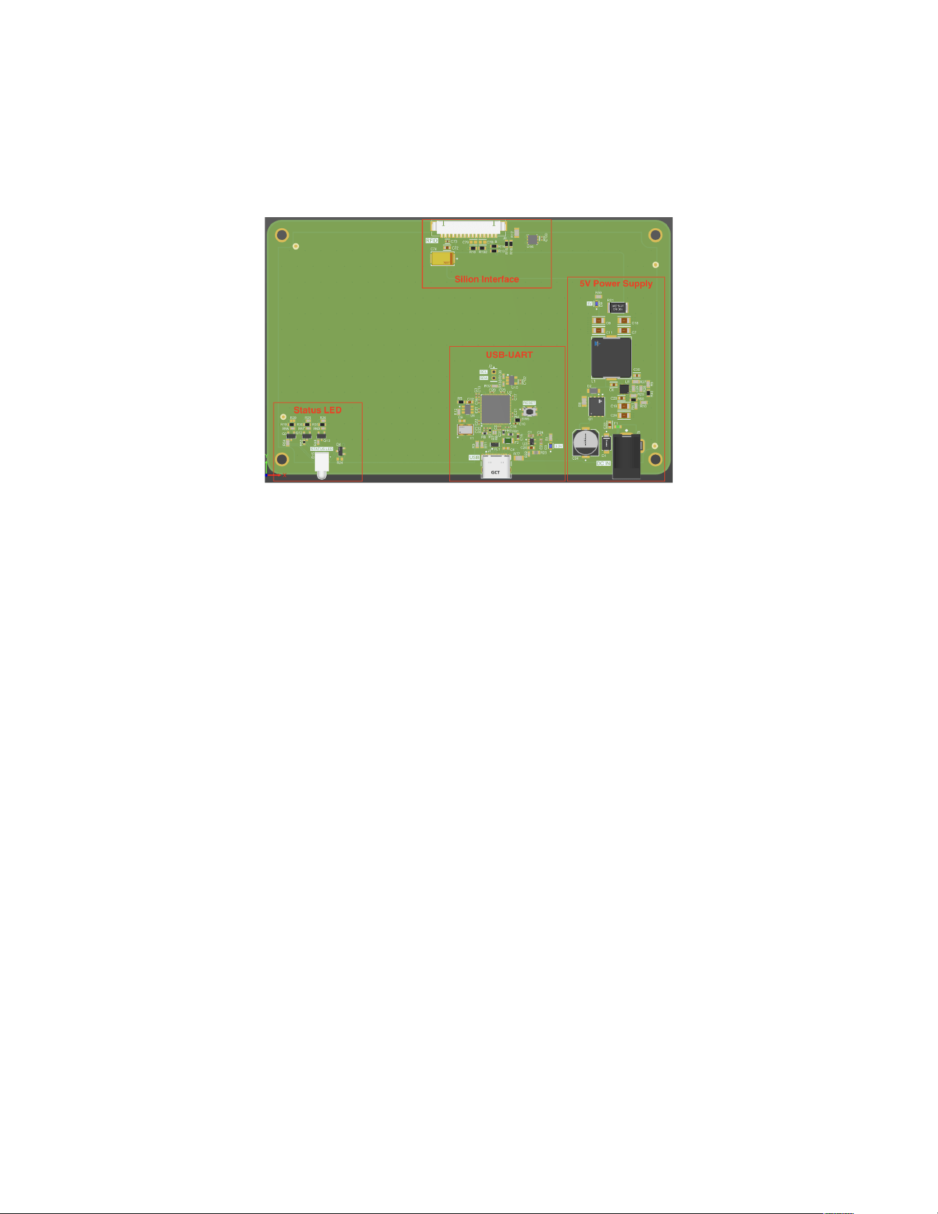
3.3 Interface PCB
The interface PCB integrates the RFID module with standard host systems and performs all
required power and signal management.
Figure 6 Interface PCB
USB–UART Bridge
• FT2232 Dual-Channel USB-UART IC
• Provides high-speed UART communication to the SIM7400 module
• Exposes additional channels for GPIO and LED control
Power Subsystem
• Dedicated 5V / 5A regulated power rail
• Designed to meet the peak consumption of the SIM7400 during maximum transmit
power
Silion Interface Header
• Power (5V / GND)
• UART TX/RX
• GPIO lines for module enable, reset, and general control
Status LED
• Controlled through the FT2232
• User-programmable for read events, errors, or system heartbeat
4. So=ware Integra:on
ARGUS communicates with the SIM7400 through a direct serial channel exposed via USB. This
allows:
• Access to official Silion APIs with no custom driver layer
• Simple PC integration with either Java, C, or C#/.NET
• Easy implementation of high-level functions including:
o Tag inventory
o Antenna switching
o Region configuration
o Power adjustments
o Real-time telemetry
Because the system uses standard UART-over-USB, it is compatible with most operating
systems without additional software requirements beyond Silion’s SDK.
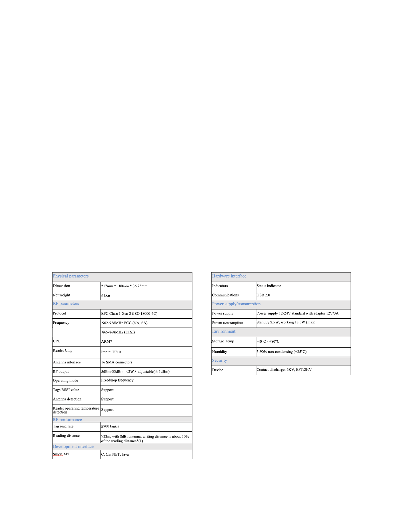
5. Technical Specifica:ons
The following specificaCons are derived from the Silion SIM7400 RFID module and apply to the
Amazon ARGUS.
Figure 7 Technical Speci fica2ons

FCC Warnning:
This equipment has been tested and found to comply with the limits for a Class B digital device,
pursuant to part 15 of the FCC Rules. These limits are designed to provide
reasonable
protection againstharmful interference in a residential installation. This equipment generates,
uses and can radiateradio
frequency
energy
and,
if
not
installed
and
used
in
accordance
with
the
instructions,
maycause
harmful
interference
to
radio
communications.
However,
there
is
no
guarantee
thatinterference
will
not
occur
in
a
particular
installation.
If
this
equipment
does
cause
harmfulinterference to radio or television reception, which can be
determined by turning the equipmentoff
and
on,
the
user
is
encouraged
to
try
to
correct
the
interference
by
one
or
more
of
thefollowing measures:
•
Reorient or relocate the receiving antenna.
•
Increase the separation between the equipment and receiver.
•
Connect the equipment into an outlet on a circuit different from that to which the receiver is
connected.
• Consult the dealer or an experienced radio/TV technician for help.
Caution:
Any
changes
or
modifications
to
this
device
not
explicitly
approved
by
manufacturer
could void your authority to operate this equipment.
This
device
complies
with
part
15
of
the
FCC
Rules.
Operation
is
subject
to
the
following
two
conditions:
(1)This
device
may
not
cause
harmful
interference,
and
(2)
this
device
must
accept
any
interference received, including interference that may cause undesired operation.
This
equipment
complies
with
FCC
radiation
exposure
limits
set
forth
for
an
uncontrolled
environment.
This
equipment
should
be
installed
and
operated
with
minimum
distance
20cm
between the radiator and your body.