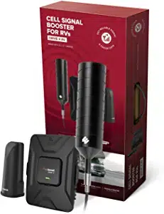
TUKO Professional
Cellphone Signal amplifier
Before installation, Ensure adequate separation between the locations of the outside
antenna and Inside antenna-at least 7.8m.
1.FIND AREA OUTSIDE WITH STRONGEST SIGNAL
Using your phone, identify the outside location with the strongest signal. Generally, this is found on the side facing
your nearest cell tower and as high as possible.
Note that Bars are not always a reliable measure of signal. The best way to confirm signal coverage is the ability to
place and hold a call. For specific dB signal measurements, use the methods below. Note that dB measurements
appear as a negative number where the closer to 0,the stronger the signal(eg.-100 dB would be considered a weak
signal while-65dB a strong signal).
Apple iPhones: Dial 3001#12345# and press Call In the top-left corner, a dB number appears /instead of bars.
Android devices: download the app "Network Signal Info" in the Google Play store.
This signal booster requires a minimum cellular signal reading of-100dB at the location of the outside antenna.
Signal between-70dB and-90dB is recommended for best performance.
2.INSTALL THE OUTSIDE ANTENNA
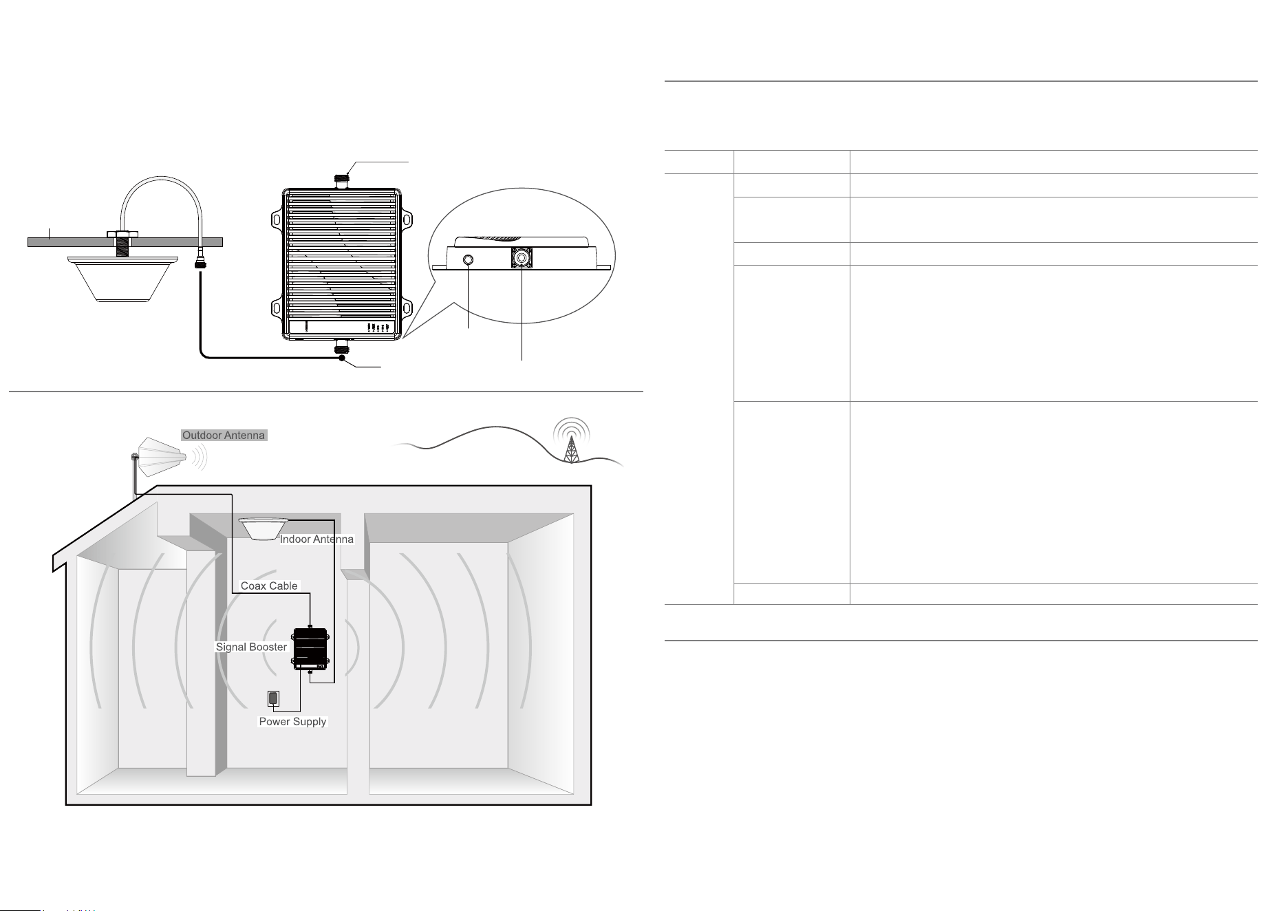
3.INSTALL THE SIGNAL BOOSTER AND INSIDE ANTENNA
For the installation of indoor antennas, remove the octagonal plastic nut that comes with the antenna and open a hole
with a diameter of 20mm at the location where the ceiling needs to be installed. Thread the antenna wire and threaded
end into the hole and tighten the octagonal plastic nut from the threaded end onto the thread.
Please note: Be sure to provide enough separation from outside antenna-at least 7.8m . Connect one end of the
connecting wire to the antenna and the other end to the host MS interface
To install the booster, select a location that is near the inside antenna and a working AC outlet. Use the supplied screws
or appropriate screws for surface of mounting location and dill through screw tab holes on booster (see Booster
Components Diagram illustration)and mount the booster to a wall.
Connect the inside antenna and booster by connecting one end of the provided 8m of coax cable to the inside antenna
and the other end of the cable to the booster port marked "MS" and hand-tighten the connection.
Next, connect the outside antenna and booster by connecting the remaining end of the 15m cable leading from the
outside antenna to the port of the booster marked "BST" .
4.CONNECT POWER
Connect the AC power cord to the booster and plug into a 110V AC power outlet. Once the booster has been
completely assembled, turn the booster's power switch on.
Note: If the Power LED does not turn ON or the Alert LEDs continue to flash, see the Troubleshooting section. This booster ls
rated for 9-15V input voltage.DO NOT use the booster with a higher voltage power supply. This can damage the booster, cause
personal injury and void your warranty.
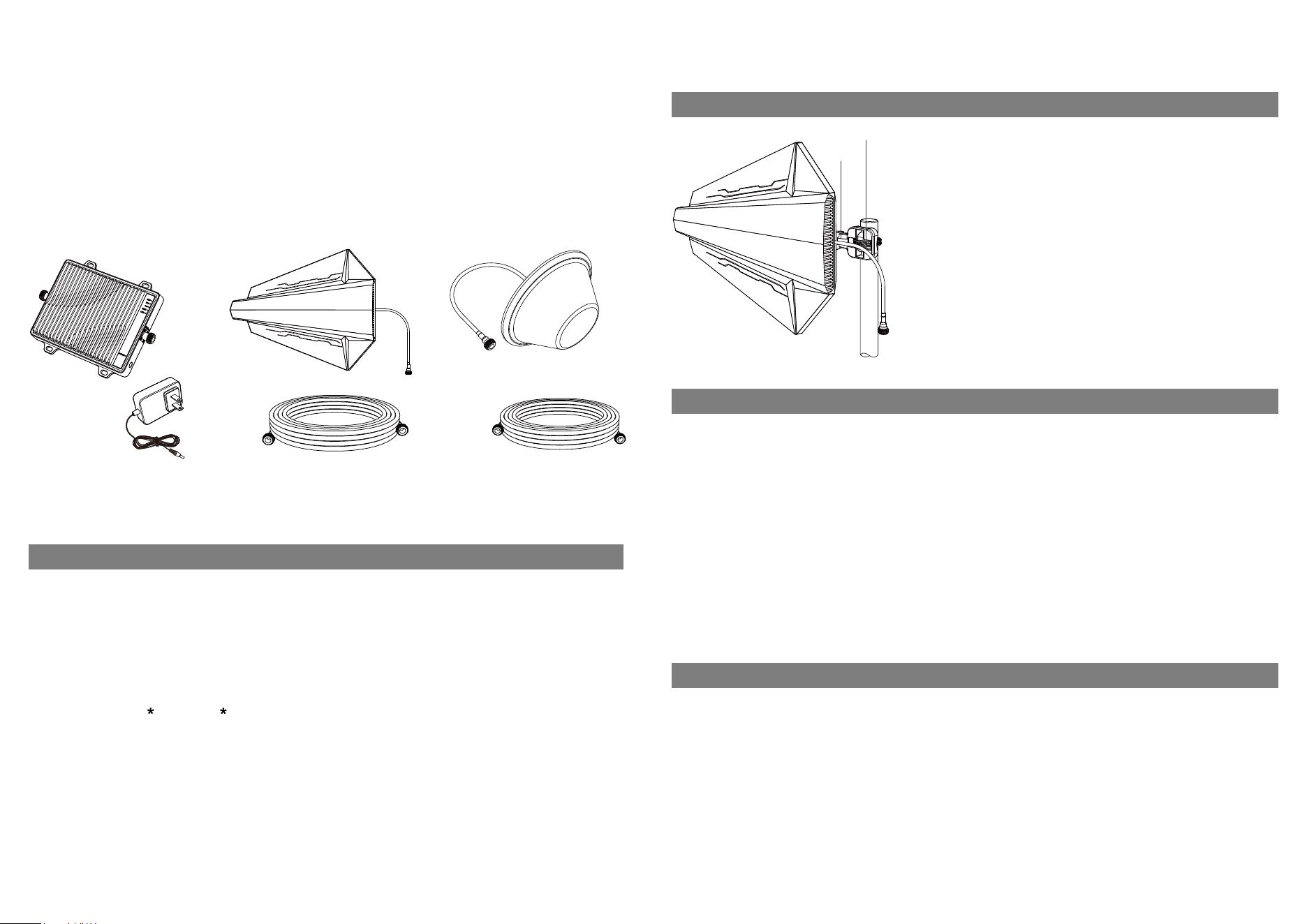
Once you have located the area of strongest signal, mount the antenna to
a pole or pipe(not icluded) at the highest possible elevation. The directional
Outdoor antenna works best when facing the direction of your carrier's
cellular tower.
When installing the outdoor antenna, insert the fixing bracket into the hole
of the outdoor antenna bracket and tighten the screws to find a suitable
position, and fix the antenna and the pipe or rod with hose clamp.Keep the
connections loose enough to allow the antenna to rotate until the optimum
direction is found.
Note:The outside antenna may be installed on a variety of pipe angles.
Ensure that themounting area has at least a 12-inch radius clear of
obstructions and other radiating elementsand orient the antenna verticall.
Once the outside antenna is secured to a pipe or pole, connect one end of
the provided 50 ft. coax cable to the antenna and tighten the connection.
Contents
Booster & Power Supply
Bracket
Hose Clamp
Outdoor Antenna - Directional Yagi
Outdoor Cable - 3D-FB 65.6feet
Outdoor Antenna Assembly
Indoor Antenna - Directional Panel
Indoor Cable - 3D-FB 32.8feet
1 2
Quick Install Guide
If you Want to Improve Coverage
1.Find a location that receives a stronger signal and relocate the outside antenna to hat location.
2.Optimize the Outdoor antenna angle.
3.Increase the distance between the outside and inside antenna.
Install Overview
Indoor Antenna
Ceiling
Connector to Indoor Antenna
Power Jack
Connector to Outdoor Antenna
LED Indicators
Condition
Power Lamp GREEN SOLID
NO LIGHT
GREEN FLASHING
YELLOW SOLID
YELLOW FLASHING
YELLOW / RED
FLASHING
RED SOLID
lndication
Power on indicator is always on.
The booster is operating normally.
Automatic Gain Control (AGC) is-active and self-adjusting.
This is part of normal operation.
No mobile phone users, entering sleep mode.
In this state, the booster can be used normally, which refers to the weak self-
excited oscillation caused by the close installation distance of two antennas,
and the yellow light will flash when the booster enters the weak self-excited
processing program; After the treatment, the lamp off booster is in a normal
state. If the lamp has not been off, reinstall the antenna and extend the distance
between antennas.
Strong self-excited oscillation caused by external interference or the installation
distance between the two antennas is too close. At this time, the booster enters
the strong self-excited processing program. If the light goes out during the
processing, it indicates that the booster can work normally. If the light does not
go out and turns into a red light, the booster is turned off in this frequency band,
Handling method: find the interference source to eliminate interference, reinstall
the antenna, open the distance between antennas, and re energize until the light
goes out.
Power off this frequency band (power on again when using).
5-Frequency
signal Lamp
3 4
2-Year Warranty
Thank you for your TUKO purchase.
TUKO warranties its products for two years from the date of purchase against
This warranty does not apply to any product determined by TUKO or have been subjected to misuse, abuse, neglect,
or mishandling that alters or damages the product's physical or electronic properties
This is a CONSUMER device.
BEFORE USE, you MUST REGISTER THIS DEVICE with your wireless provider and have your provider's consent.
Most wireless providers consent to the use of signal boosters. Some providers may not consent to the use of this
device on their network. If you are unsure, contact your provider.
You MUST operate this device with approved antennas and cables as specified by the manufacture. Antennas MUST
be installed at least 20cm (8 inches) from (i.e., MUST NOT be installed within 20cm of) any person.
You MUST cease operating this device immediately if requested by the FCC or licensed wireless service provider.
WARNING: E911 location information may not be provided or may be inaccurate for calls served by using this device.
This device may operate in a fixed location only, for in-building use.
This device complies with part 15 of the FCC Rules. Operation is subject to the following two conditions: (1) This device may
not cause harmful interference, and (2) this device must accept any interference received, including interference that may
cause undesired operation.
5 6
IMPORTANT NOTE:
Note: This equipment has been tested and found to comply with the limits for a Class B digital device, pursuant to part
15 of the FCC Rules. These limits are designed to provide reasonable protection against harmful interference in a
residential installation. This equipment generates, uses and can radiate radio frequency energy and, if not installed and
used in accordance with the instructions, may cause harmful interference to radio communications. However, there is
no guarantee that interference will not occur in a particular installation. If this equipment does cause harmful
interference to radio or television reception, which can be determined by turning the equipment off and on, the user is
encouraged to try to correct the interference by one or more of the following measures:
—Reorient or relocate the receiving antenna.
—Increase the separation between the equipment and receiver.
—Connect the equipment into an outlet on a circuit different from that to which the receiver is connected.
—Consult the dealer or an experienced radio/TV technician for help.
FURTHER INFORMATION ON SIGNAL BOOSTER END-USE REGISTRATION
The following links are the currently active contacts for booster registration with u.s. wireless providers:
verizon: http://www.verizonwireless.com/wcms/consumer/register-signal-booster.html
AT&T: https://securec45.securewebsession.com/attsignalbooster.com/
T-Mobile: https://support.t-mobile.com/docs/Doc-9827
sprint: https: // www.sprint.com/legal/fcc boosters.html
u.s.Cellular: https://www.uscellular.com/uscellular/support/fcc-booster-registration.jsp
FCC Radiation Exposure Statement:
This equipment complies with FCC radiation exposure limits set forth for an uncontrolled environment .This equipment
should be installed and operated with minimum distance 20cm between the radiator& your body.
This transmitter must not be co-located or operating in conjunction with any other antenna or transmitter.
Any Changes or modifications not expressly approved by the party responsible for compliance could void the user's
authority to operate the equipment. For a complete list of antennas and cables approved for use with these boosters
see below:
FCC 27.50(d)(4) Statement: Fixed, mobile, and portable (handheld) stations operating in the 1710-1755 MHz band are
limited to 1-watt EIRP. Fixed stations operating in the 1710-1755 MHz band are limited to a maximum antenna height of
10 meters above ground.
Marning: Un-authorzed antennas, cables, and/or coupling devices are prohited by new FCC rules, Please contact FCC
for details: 1(888)-CALL-FCC.
TXDS-1001 TXBZ-3001 TXDS-5015 TXXD-2001
3D-FB 65.6feet 3D-FB 98.4feet 3D-FB 32.8feet
Network Protection Description
Anti-Oscillation Function
Upon detecting an oscillation signal, the booster will stop the transmission of uplink and downlink signals separately
within 0.3 to 1.0 seconds. If no abnormal signal is detected after 65 seconds, the system will resume detection, which can
be repeated a maximum of 2 times. After that, the booster will shut down automatically until it is manually restarted by the
user.
AGC Function: Power Control / Shutdown Function and Noise Limiting Function
The amplifier amplifies signals without modifying or distorting any input signals from the base station and mobile devices.
It automatically adjusts the gain and power of the amplifier to keep signals within a controllable range. When the input
signal strength exceeds this range, the booster will automatically reduce the power of the uplink/downlink signals until the
booster shuts down automatically.
Sleep Function:
If the signal booster remains unused for five minutes, it will automatically reduce the gain and enter sleep mode until a
signal is detected.
Each signal booster is individually tested, and its parameters are pre-set at the factory to ensure compliance with relevant
FCC regulations. Users cannot perform any settings or adjustments to the signal booster via software or hardware. Only
the factory has the authority to program and configure the device software.
Note : TUKO declares that the inside antenna with 3D-FB 32.8 feet is only used with TXXD-2001,and the inside
antenna with 3D-FB 98.4 feet is only used with TXBZ-3001.
Have questions?
We have answers! Reach out to our US-based support team:
Call: +86 13760469652
Email: [email protected]
Visit: https://www.antukoantenna.com/
Troubleshooting
Problem
Signal booster has no power.
After completing installation,
indoor signal coverage has not
improved.
Resolution
Connect the power supply to an alternate power source.
Verify that the power source is not controlled by a switch that has removed power
from the outlet. If the POWER LED on the signal booster remains OFF, contact tech
support at: [email protected]
(1)Verify that all cable connections are tightly fitted. (2)Try further separating the
booster and antenna.(3)Verify that there is usable signal where the outside antenna
is placed.
Remember: Bars are not always a reliable measure of signa. The best way to
confirm signal coverage is the ability to place and hold a call.
7 8
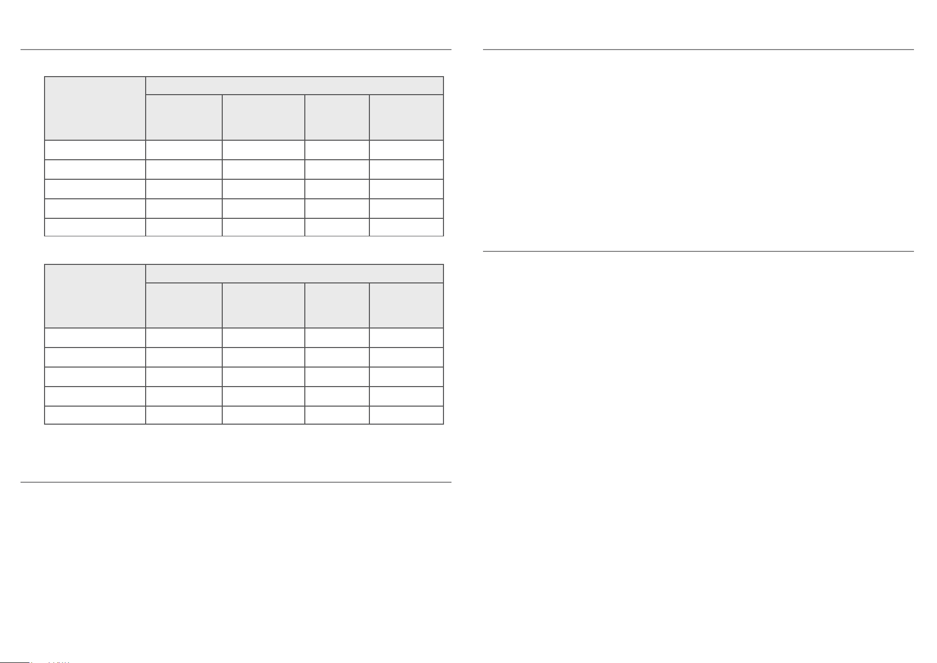
Outside Antenna
Frequency
Range
(MHz)
Antenna and Cable
3D-FB 32.8feet
Cabel Loss
(dB)
3D-FB 65.6feet
Cabel Loss
(dB)
TXDS-1001
Ant Gain
(dBi)
TXDS-5015
Ant Gain
(dBi)
698-716
776-787
824-849
1850-1915
1710-1755
3
3.1
3.3
5.1
4.9
5.9
6.2
6.5
10.3
9.7
7
6.8
8
9.3
9.4
8.4
7.2
7.7
8.2
8.8
Inside Antenna
Frequency
Range
(MHz)
Antenna and Cable
3D-FB 32.8feet
Cabel Loss
(dB)
3D-FB 98.4feet
Cabel Loss
(dB)
TXXD-2001
Ant Gain
(dBi)
TXBZ-3001
Ant Gain
(dBi)
728-746
746-757
869-894
1930-1955
2110-2155
3
3
3.3
5.2
5.4
9
9
9.9
15.5
16.2
2.5
2.5
1.5
4.8
4.6
6
6
6.4
8.7
8.6