WiFi 2.4G&5G
7-inch Touchscreen
0.1mm
500mm/s
1500g
<50w
DC24V 2.75A
Stepper Motor
5°C~35°C
35%-70%
U8-310 U8-390
Model Number
Max Material Size
Max Cutting Screen Size
Connection
Display
Cutting Accuracy
Max Cutting Speed
Max Cutting Pressure
Power Rating
Input Voltage
Drive System
Operating Temperature
Operating Humidity
Machine Dimensions
Net Weight
Main Unit *1
Automatic
tool holder*1
Cutting
blade*1
Adapter*1
Power Cord*1
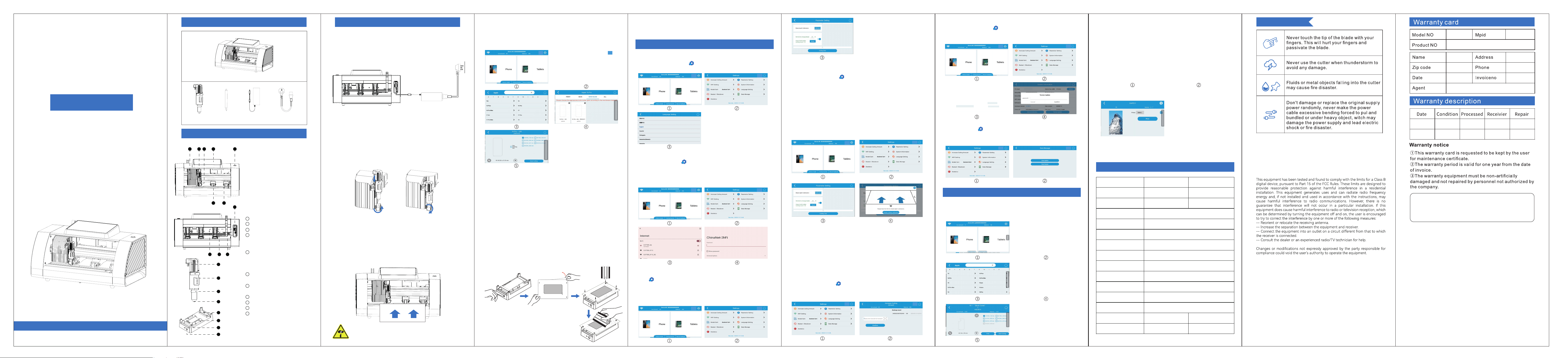
①Connect the power cord to the adapter, plug one end of the power cord
into a power socket, plug one end of the adapter cable into the power
inteace of the lm cutting machine and lock it, then install the cutter head
into the tool holder slot next to the driver, ensuring it is xed.
②After connection, press the [Power Button] to sta the device.
Product List User Instructions
Machine Settings
Precautions
Product parameters
Appearance and Functions
U8
Film cutting machine
Instruction Manual
①Carriage
②Electric blade Holder
③blade Holder Clip: to x the electric
blade holder
④Touch Screen
⑤Power Button: to sta the machine
⑥Pressure Roller: Holds lm in position
during cutting
⑦Film Feed Sensor: Auto-detects
lm inseion
⑧Power Input Po: For power adapter
connection
Network Po
USB-A Po (Power Supply Only)
USB-C Po (Power Supply Only)
USB Po: Inse this connector into
the vehicle-mounted cutter inteace
during installation
Blade Needle Slider: when replacing
the blade needle, gently push the slider
to extend the blade needle and take
out the blade needle to be replaced
Tool holder base: Rotate the tool
holder clamping bolt to lock the tool
Blade tip: Adjust the exposed length
according to the thickness of the material
Upper and lower xtures
Left and right xtures
Power inteace
Clamp/Release Button
9
10
11
12
13
14
15
16
17
18
19
12
13
14
15
1.Power Connection and Startup
1.Language Settings
2.WiFi Settings
On the homepage, select the mobile phone brand/model/lm type you need
to cut, and click 【Scan Code to Cut】
Note: After replacing the blade needle or blade holder, please perform blade needle
calibration; otherwise, abnormal cutting may occur. For specific operations, refer
to - Machine Settings - 【blade Depth Calibration】.
4.Starting Cutting
After the lm cutting machine nishes cutting, the protective lm will be ejected.
5.Cutting Completed
6.Starting Film Application
2. Install the Cutter Blade Holder
①Prepare the electric blade holder and loosen the blade holder clip
counterclockwise;
②Place the electric blade holder veically into the blade holder clip and
inse it into the tool inteace of the carriage;
③Tighten the blade holder clip clockwise to complete the blade holder
installation.
①Before staing lm application, connect the lm cutting machine and the
lm application xture with a Type-C power cord, and long press the
【Clamp/Release】 button on the lm application xture to keep the clamp in
the released state;
②Place the mobile phone horizontally on the lm application xture with the
screen facing up, and tap the 【Clamp/Release】button on the lm
application xture to x the mobile phone; Note: The mobile phone camera
should face the "Top" direction of the clamp;
③Clean the mobile phone screen with alcohol and a lint-free cloth;
④ Separate the cut lm sheet from the base plate, and use a squeegee to x
the 4 cut positioning holes on the lm sheet to the 4 positioning posts of the
lm application xture;
⑤Use a squeegee to make the lm sheet closely adhere to the mobile phone
screen, and peel o the waste material.
7.Film Application Completed
Tap the 【Clamp/Release】 button on the lm application xture to take out
the mobile phone, and the lm application is completed.
3.Placing Materials
①Prepare a protective lm to be cut, and conrm that the protective lm is
at, the lm layer is complete, and there is no bending, folding or
delamination;
②Place the lm sheet in the indicated area;
③The machine will automatically sense and take in the lm paper;
④If you need to replace with other lm paper, press the power button once
to eject the lm paper.
Top
Bottom
On the homepage, click the【 Settings Button】to enter the settings
inteace, then click [Language Settings] to switch.
On the homepage, click【 Settings Button】, enter the settings inteace,
click 【WiFi Settings】to connect to WiFi and enter the password, then wait
for the machine to successfully connect to the WiFi network.
Click【 Settings Button】on the homepage, enter the settings inteace,
select【Parameter Settings】, and adjust according to actual usage.
①On the homepage, click【 Settings Button】, enter the settings
inteace, select【Parameter Settings】, scroll down to nd the【Knife Depth
Calibration】option, and click【Calibrate】.
②Please follow the "Placing Materials" steps in the "User Instructions" to
place a protective lm to be cut.
③According to the text instructions on the touch screen, click【Sta Cutting
Calibration】, and the machine will automatically cut 40 line segments with
dierent knife depth levels on the lm sheet.
④After the cutting is completed, nd the last line segment with visible
cutting marks on the lm sheet, select the corresponding line segment
number and click 【Calibrate】to complete the knife depth calibration.
4.Knife Depth Calibration
5.Self-service Value-added Times
16
17
18
19
300mm
200mm
410mm
295mm
410*220*202mm
6.8kg
510*220*202mm
8.5kg
Top
Bottom
Top
Bottom
⑥
⑤
6.APP Upgrade/Data Update
①On the homepage, click【 Settings Button】, enter the settings
inteace, click【System Information】, then click【Version Update】, enter
the update password: 1313, and wait for the APP to update successfully.
For the placement position of the film sheet, refer to the dotted line
guide. The cutting tool is sharp; do not put your hands into the cutting
area to avoid cuts.
Note: The small positioning hole at the top is fixed on the
small positioning post at the
"Top" end, and the large positioning hole at the tail end is
fixed on the large positioning
post at the "Bottom" end;
Note: The machine supports RBAC network. Please click【Parameter Settings】on the
settings page, scroll down to find Public WiFi, and click【Settings】.
Note: [Scan Code to Cut] is only applicable to films with an attached QR code; if you
want to apply the film using a film application jig, you need to check [Trace-Free Film
Application]. Hard films only support [Scan Code to Cut].
Note: The parameter settings on this interface are only applicable to ordinary cutting
(when no material is configured). During code - scanning cutting, the system will
automatically adopt preset parameters and will not be affected by the parameter
settings on this interface.
On the homepage, click【 Settings Button】, enter the settings inteace,
click【Value-added Times】, enter the value-added barcode number, then
click【Conrm】to complete the recharge.
Note: The application jig is not included as standard
equipment and must be purchased separately.
②After conrming that the machine is connected to the network, on the
homepage, click【 Settings Button】, enter the settings inteace and
select 【Data Management】, click【Data Update】, and the data will be
automatically updated and completed.
4. Select the corresponding printer and click "Print."
5. Laminate the printed image, use the lm cutter to cut it,
and nally apply the completed back lm to the phone.
Back film printing operation settings
1. Stathelmcutterandphotoprinter,bothmachinesmustbeonthesame
network.
2. Select the phone model for which you want to create a back lm and click "Print”
3. Scan the QR code with your phone (the phone must be on
the same network as the lm cutter and photo printer), choose
the image you want to print and upload it, adjust it to the
appropriate size, and add patterns and text if desired.
3.Blade force/Speed/Blade Depth
1 2 4 53
6 7
8
9 10 11
FCC Radiation Exposure Statement
The antennas used for this transmitter must be installed to
provide a separation distance of at least 20 cm from all persons
and must not be co-located for operating in conjunction with
any other antenna or transmitter.