
USER MANUAL & ASSEMBLY INSTRUCTIONS
VINYL CUTTER
Be sure to review the contents of this manual before attempting to operate the equipment.
This manual should be located where it can be easily referenced by all users of themachine.
IMPORTANT :
NEED HELP? CONTACT US!
Have product questions? Need technical suppo? Please feel free to contact us:
855-385-1880 CustomerSe[email protected]
Vinyl Cutter
KI-720/870
01

CONTENTS
Ⅸ. HOW TO USE THE SOFTWARE AND CUT OFF THE CONNECTION
BETWEEN THE SOFTWARE AND THE MACHINE
Ⅰ. PACKAGE CONTENT
3
Ⅱ. TECHNICAL PARAMETERS
4
Ⅲ. PRECAUTIONS
5
Ⅳ. INTRODUCTION FOR MAIN PARTS
6
Ⅴ. OPERATION INSTRUCTION
7
Ⅵ. MACHINE ASSEMBLY DIAGRAM
8-11
Ⅶ. HOW TO USE THE PRODUCT
12-19
Ⅷ. HOW TO CONNECT THE PRODUCT TO THE
20
21-22
Ⅹ. DOWNLOAD LINK OF SOFTWARE
23-24
02
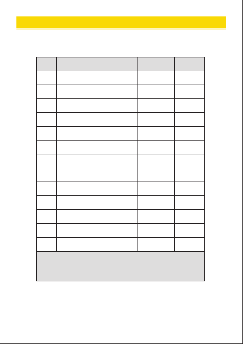
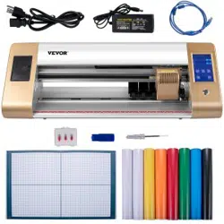
To protect the machine, please only use the accessories
attached.
1
2
3
4
5
6
7
8
9
10
11
12
13
Ltem
Cutting plotter
Power supply cable
Blade
Blade holder
Pen holder
Ball pen core
COM connection cable
USB cable
Spanner
USB driver
Bracket screws
Operation manual
Stents
Quantity
1
1
1
1
1
1
1
1
1
1
1
1
1
Unit
Set
Pc
Box
Pc
Pc
Pc
Pc
Pc
Pc
Pc
Bag
Pc
Set
Ⅰ.PACKAGE CONTENT
03
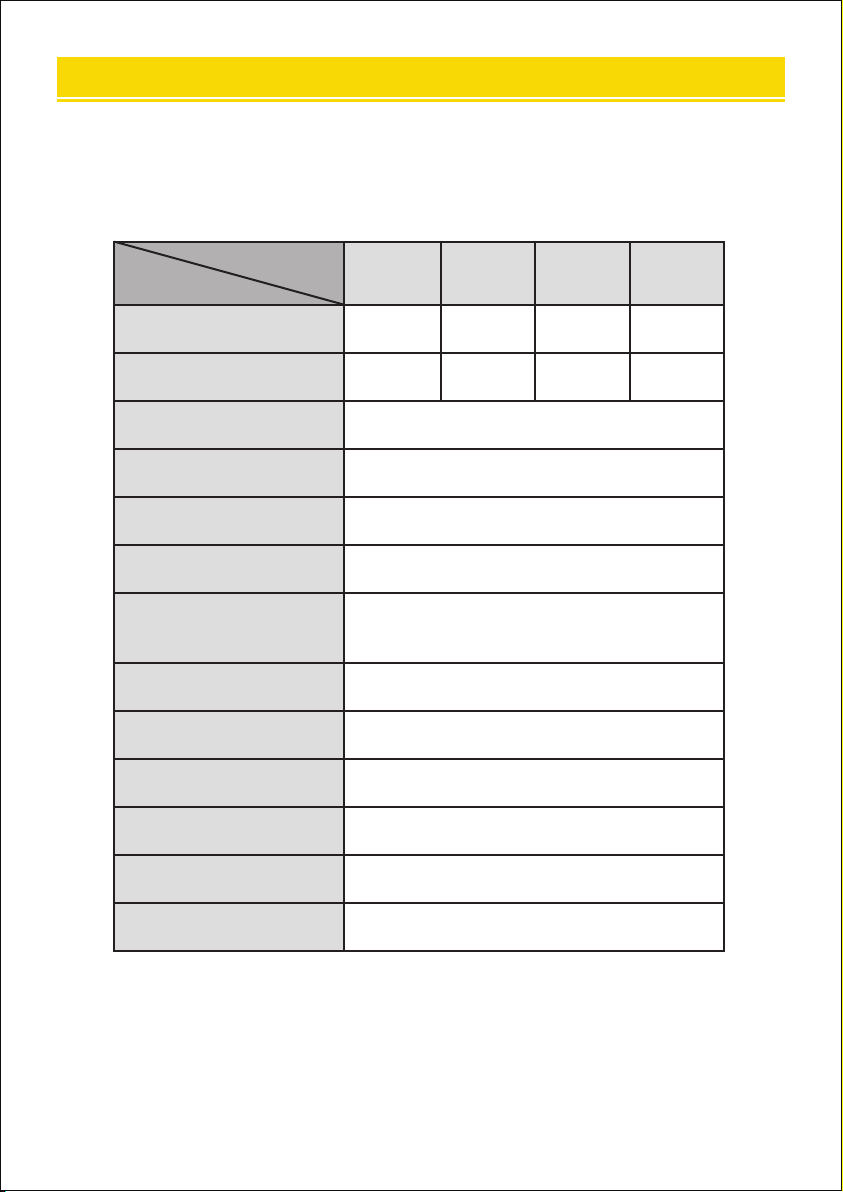
Max. feeding width
Max. cutting width
Cutting thickness
Speed/Pressure
Buer
LCD display
Real-time speed
adjustment
Inteace
Re-cutting function
Re-cutting accuracy
Resolution ratio
Language format
Voltage
≤1mm
20-800mm/s
1-4M
CN/EN
Suppo
COM+USB
Suppo
0.127mm
0.0245mm/step
DMPL/HPGL
AC 85-264V
Model
375 720 870 1350
375mm 720mm 870mm 1350mm
285mm 630mm 780mm 1260mm
Item
Ⅱ. TECHNICAL PARAMETERS
04

Protective material must be removed before turning on the cutting
plotter.
Check the label on the back side of the plotter to conrm that the rated
voltage required by the plotter matches the voltage of the power base.
Firstly make sure that the power switch is o, then plug the power
supply into a grounded power outlet.
Please do not touch the power cord with wet hands to avoid electric
shock.
Please only use the power cord, data cable provided with this product,
or manufacturer-approved replacements.
Please do not drop metal objects and liquids into the machine to avoid
malfunction.
After shutting down, you must wait another 5 seconds to turn on the
cutting plotter again.Otherwise ,it will cause damage to the cutting plotter.
In thunderstorms, turn the power switch to o and unplug the power
cord.
Please do not privately change the manufacturer's components.
Manufacturer resees the right to change product specications without
prior notice.
The manufacturer only bears the legal obligations of the product itself
sold to the users, and does not bear other losses caused by the malfunc
tion of the products.
Without our company’s permit, no pa of this manual can be copied or
transmitted in any name.
Do not drag the carriage by hand.
If there is an abnormal sound after powering on the machine, please turn
o the power immediately and contact the after-sales depament for
feedback.
1
2
3
4
5
6
7
8
9
11
12
13
14
10
Ⅲ. PRECAUTIONS
05
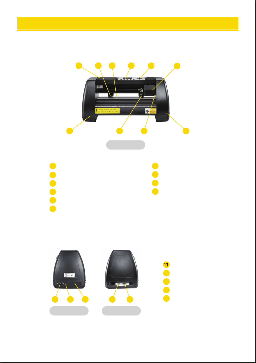
KI Model
1 2 4 5
6
10
3
9 8 7
Left side Right side
131211 1514
Power connection
Fuse holder
Power switch
USB po
COM po
15
11
12
13
14
Cover for rail guide
Pinch roller kit
Roller for feeding paper
Screen
Buttons
Carriage
1
2
4
5
6
3
The right cover
Reset switch
Blade clamp
The left cover
10
9
8
7
Ⅳ.INTRODUCTION FOR MAIN PARTS
06
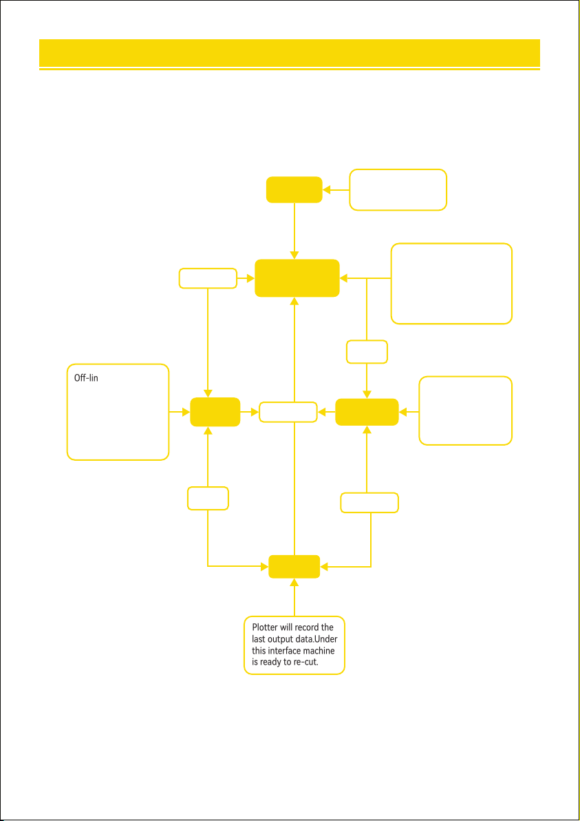
Ⅴ. OPERATION INSTRUCTION
Speed 800mm/s
Force 150g
Welcome
Plotter sta screen.lt
will take 3 seconds for
machine initialization.
Setup
Setup
One/Pause
One/Pause
One/Pause
O-line inteace.ln this
status,youcan move the
carriage or metal roller
by pressing the button
to check the quality of
the pattern or to set
the origin location.
This screen shows the
baud rate and speed
grade.You can set up
the baud rate in this
inteace.
e Speed+0Vale
Baud 9600
Redraw
Plotter will record the
last output data.Under
this inteace machine
is ready to re-cut.
After initializing,the machine
automatically resel.Under
this inteace you can adjust
the cutting speed and
force,test the machine,do
on-line processing.
Move X0
Y0
07
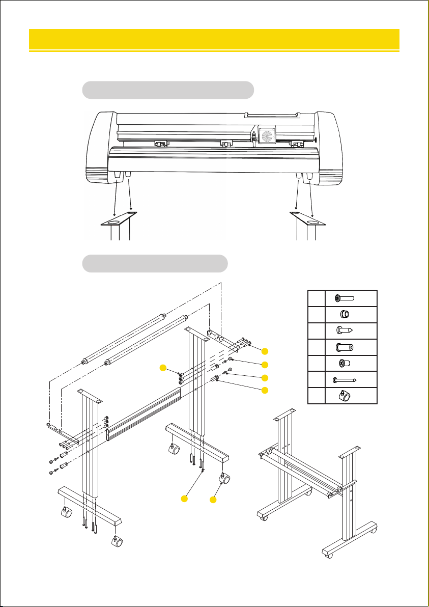
B
Bracket assembly diagram
Install the machine on the bracket
A
1
2
3
4
5
6
7
6
4
4
4
6
8
4
*
*
*
*
*
*
*
1
2
4
3
5
6
7
Ⅵ. MACHINE ASSEMBLY DIAGRAM
08
09
Blades should be replaced eve 6 months. Your blade may need to be
replaced more often if you are cutting thicker material such as ock, glitter,
or re ectives.
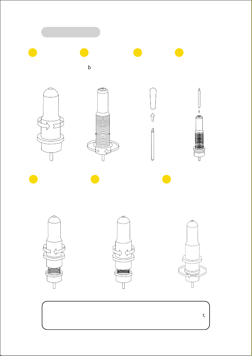
C
Blade assembly
1 2 3 4
Unscrew the cap
from the Blade
Carriage.
Set the brass ring on
the blade carriage to
a fully down position.
Remove the
protective
cover from a
new blade.
Inse the blade into
the top of the blade
carriage.
5 6 7
Screw the cap back
onto the blade
carriage.
Adjust the carriage cap until
the blade is protruding
approximately
1/64 of an inch.
Adjust the brass ring until it
ts snug against the cap.
This will help keep the cap
in place during operation.
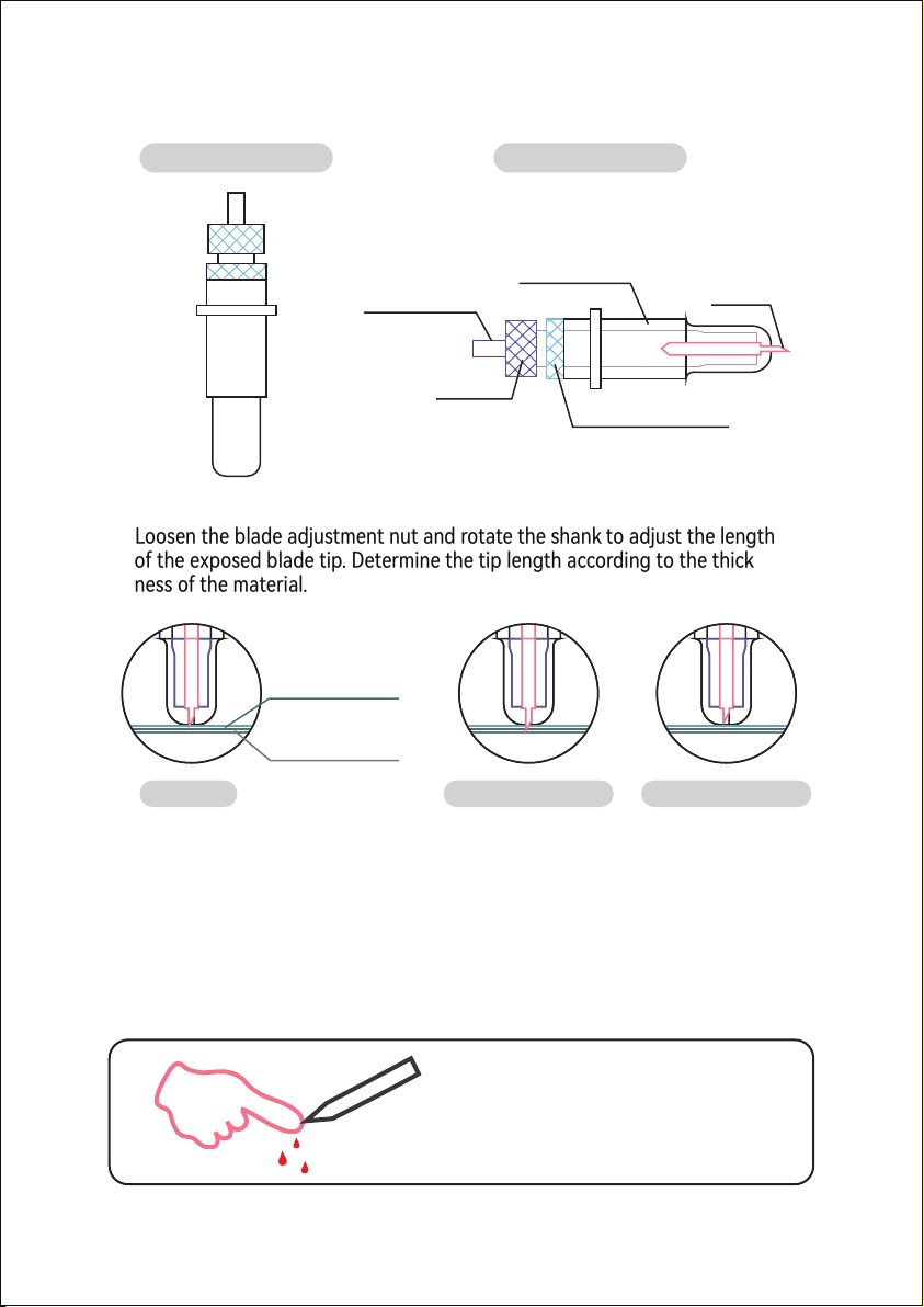
1). Assembly the blade into holder, see as below:
2). Loosen the blade adjustment nut and rotate the shank to adjust the length
of the exposed blade tip. Determine the tip length according to the thick
ness of the material.
Correct Blade tip is too long Blade tip is too sho
Materioal thickness
Base thickness
Pressing rod
Blade cover
Blade
Shank
Blade adjustment nut
(Appearance view) (Exploded view)
① Press the pressing rod when you want to change blade. Take out the blade
when it is exposed.
② Assembly the blade holder into wagon:
a, Loosen the xed screw on tool holder
b, Put the blade holder into tool holder
c, Tighten and x the blade holder when it arrives to correct position
Tips: Do not touch the blade tip by nger,
otherwise, your nger will be injured and the
tip will be blunt.
10
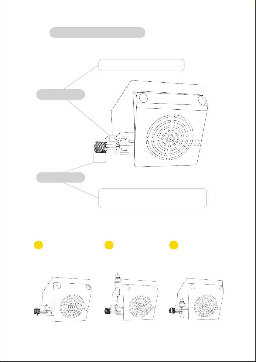
D
Installation steps of cutterbed
Tighten the locking knob
on the carriage arm.
Loosen the locking knob
on the carriage arm.
Place blade carriage
into the carriage arm.
1 2 3
Holds the blade carriage in place.
Allows access to the blade/pen carriage slots for
exchanging/replacing carriages.
Carriage slot
Locking knob
11
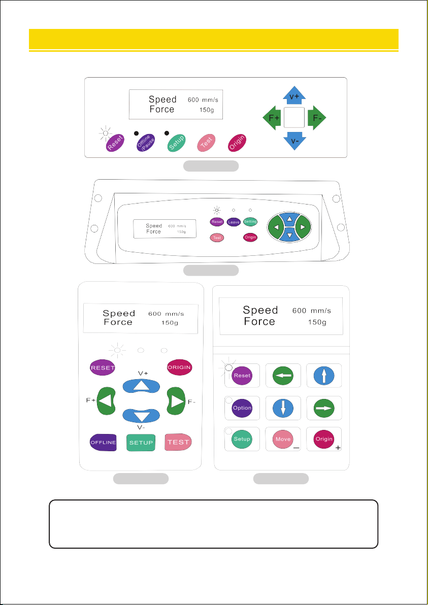
The main screen of the cutter allows you to set the main settings of the cutter, including
the cutting speed and cutting force options. It also allows you to cut a test pattern or
check the amount of force currently set.
KI Model
SK Model
EH Model KH Model
Ⅶ. HOW TO USE THE PRODUCT
12

Resets by stopping the cutter, and setting the origin
of the carriage arm to its right most position.
Accesses the Oine/Pause mode.
Accesses the Setup mode.
Will cut a small test shape so that the current force and
speed settings of the cutter can be tested. You can use
this to determine the proper cutting speed and force
settings needed for dierent materials without wasting
large amounts of material from cutting full designs.
Used to test z-axis functionality (by dropping the blade
down if the carriage is functioning correctly) or to set a
new origin point when the machine is in its Oine mode.
Adjusts the cutting speed. A cutting speed of 300 mm/s is a
reasonable default speed that can be used for most cuts.
When working with smaller and more detailed images, a
slower speed may be required. When working with larger
and less clear images, a higher speed can be used to
shoen the operation time.
Adjusts the cutting force. A cutting force of 100g is a
good general staing place to work from when determin-
ing the force needed for a specic material. All cuttable
materials will depend on the amount of force needed, so
proper testing should always be made to determine the
force to use. The amount of force used should be enough
to fully penetrate the material to be cut while not enough
to cut through the backing material.
Reset button
Oine/Leave/
Option button
Setup button
Test/Move button
Origin button
V+ / V- buttons
F+ / F- buttons
13

KI Model
SK Model
EH Model KH Model
Oine mode is used to reposition the cutting material and blade to set a new staing
position for the next design. Oine mode can also be accessed while the cutter
operates and will pause the current cutting process. Although changes can be made to
the material and blade positions if Oine/Pause mode is accessed during cutting,
making changes to either setting is not normally recommended.
14

Resets by stopping the cutter and setting the origin of
the carriage arm to its right most position.
Ignore any changes made to the material or blade
positions and exits Oine/Pause mode, returning
the cutter to the main screen. Resumes any cutting
that was taking place when Oine ine/Pause mode
was entered.
Has no function in this mode.
Accepts any changes that have been made to the
material or blade positions and exits Oine/ Pause mode
returning the cutter to the main screen. Resumes any
cutting that was taking place when Oine ine/Pause
mode was entered from the new blade/material positions.
Accepts any changes that have been made to the
material or blade positions and exits Oine/Pause mode
returning the cutter to the main screen. Resumes any
cutting that was taking place when Oine/Pause mode
was entered from the new blade/material positions.
Repositions the material by moving the feed rollers. After
movements are made, you can conrm the changes by
pressing the Test or Origin buttons or cancel by pressing
the Oine/Pause button.
Repositions the blade by moving the carriage arm. After
movements are made, you can conrm the changes by
pressing the Test or Origin buttons or cancel by pressing
the Oine/Pause button.
Reset button
Oine/Leave/
Option button
Setup button
Test/Move button
Origin button
V+ / V- buttons
F+ / F- buttons
15
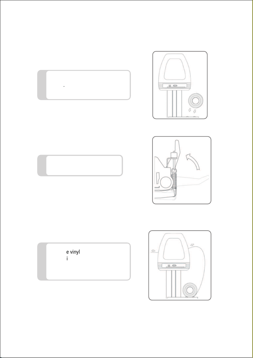
Place the roll on top of the stand
rollers.For heat press vinyl, please
ip the roll.
1
Release the pinch rollers to
release levers.
2
Feed the vinyl underneath the pinch
rollers (if working from a single
sheet instead of a roll, the vinyl can
also be fed from the front).
3
16
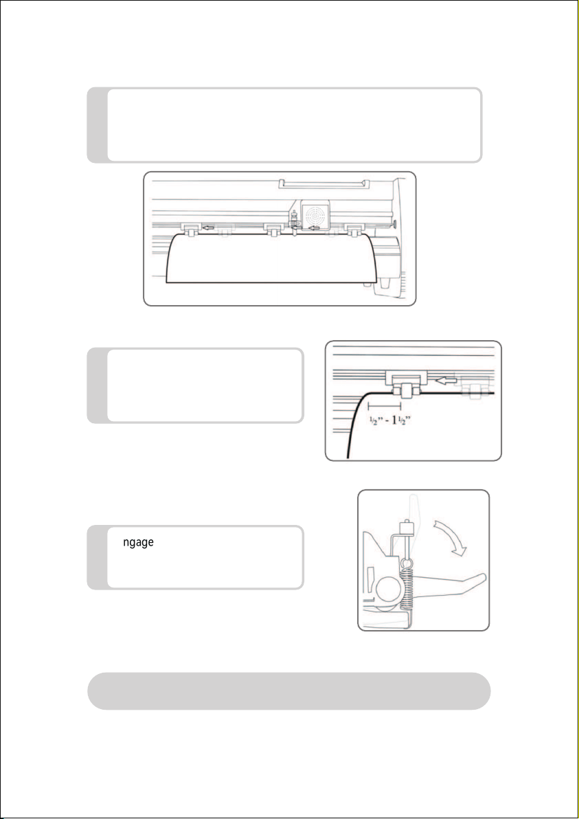
Adjust the pinch rollers so there is one roller on each side of the vinyl (and
one roller near the center on models with 3 or more rollers). Avoid
lowering a pinch roller to the gap between the two feed rollers.
4
Leave a gap of between1/2”-1 1/2”
from the edge of the roller and the
edge of the vinyl on both sides.
5
Engage the pinch rollers by pushing
down on the pinch roller release
levers.
6
If the cutter is not already on, turn it on now.
17
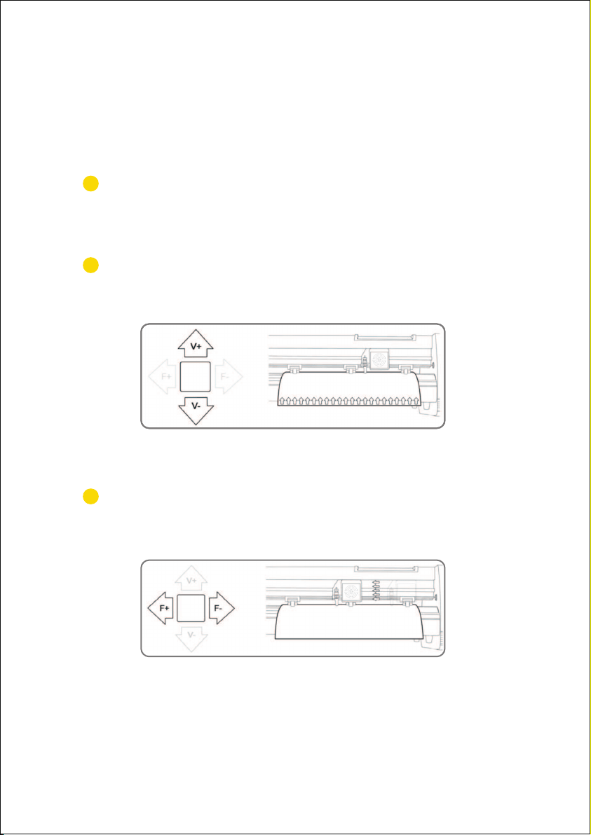
Press the OFFLINE/PAUSE button to enter oine mode.
Adjust the vinyl to where you want to make your cut to sta by using the Up and
Down arrow keys on the control panel.
Now, adjust the blade to where you want your cut to sta by using
the Left and Right arrow keys.
1
2
3
If you would like to change the position of where the cut
will be made:
18
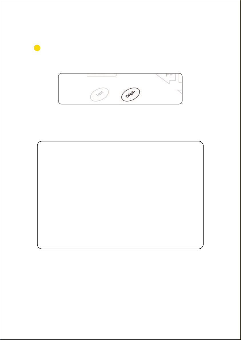
Press the origin button to tell the cutter that this is the
location where you would like the cut to begin.
4
When choosing a staing location for your design, remember that the
process will sta in the bottom right area of the design. Please leave
enough room to the left of and behind the staing location to nish your
cut.
If you would like to make other adjustments to the pressure, speed, or
other settings you can do so now. If you are setting up for your rst cut
with the machine then the default values should be a good staing point.
If you make any adjustments to your cutter, make sure that you return to
the main screen before you attempt to cut.
19

Attach the power cord to the cutter and then plug in the unit and turn
on the power.
If you use a Serial Cable to connect your cutter to a computer, then no fuher
setup is necessa. Connect one end of the cable to the cutter and the other end
to a computer, and setup is complete. If you have more than one serial connec-
tion on your computer, or you are experiencing communication issues between
your cutter and computer, then you may wish to verify that the correct COM po
is being used in your software setup, but for most users, the COM po will be
COM1.
Installing vinyl master software
SignMaster software is an easy-to-use software with the tools to help you take
your projects from concept to a ready-to-cut computer image le.
The driver is automatically installed during software installation. You do not need
to install the driver separately.
If using the USB Cable to connect your
cutter to a computer:
Ⅷ. HOW TO CONNECT THE PRODUCT TO THE SOFTWARE
20
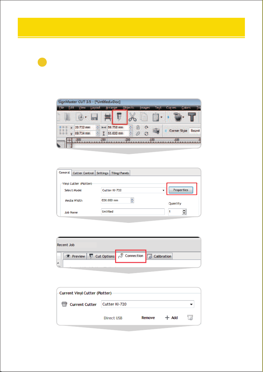
Click the cutter icon in the red box
Click propeies
Click connect
Select machine model
1
Open the software, select cut content, and click send to the
cutting plotter
Ⅸ. HOW TO USE THE SOFTWARE AND CUT OFF THE CONNECTION
BETWEEN THE SOFTWARE AND THE MACHINE
21
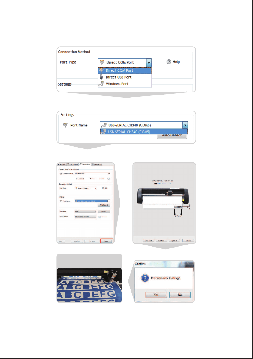
Select Direct COM Po
Select USB-SERIAL CH340 (COM)
Click Done Click cut now
Click cut now
The output is completed, the
cutting plotter is cutting
22
1
2
Download link of software:
https://fcws6.com/downloads/signmaster/SignMaster_UniverDS-
R_35_GW.exe
Frequently asked question:
When the machine is powered on, the carriage inclines, the
carriage does not move and makes noise, and the carriage
automatically moves to the right and make noise, etc., all of which
are small wheels derailing.
Solution: Refer to the repair video.
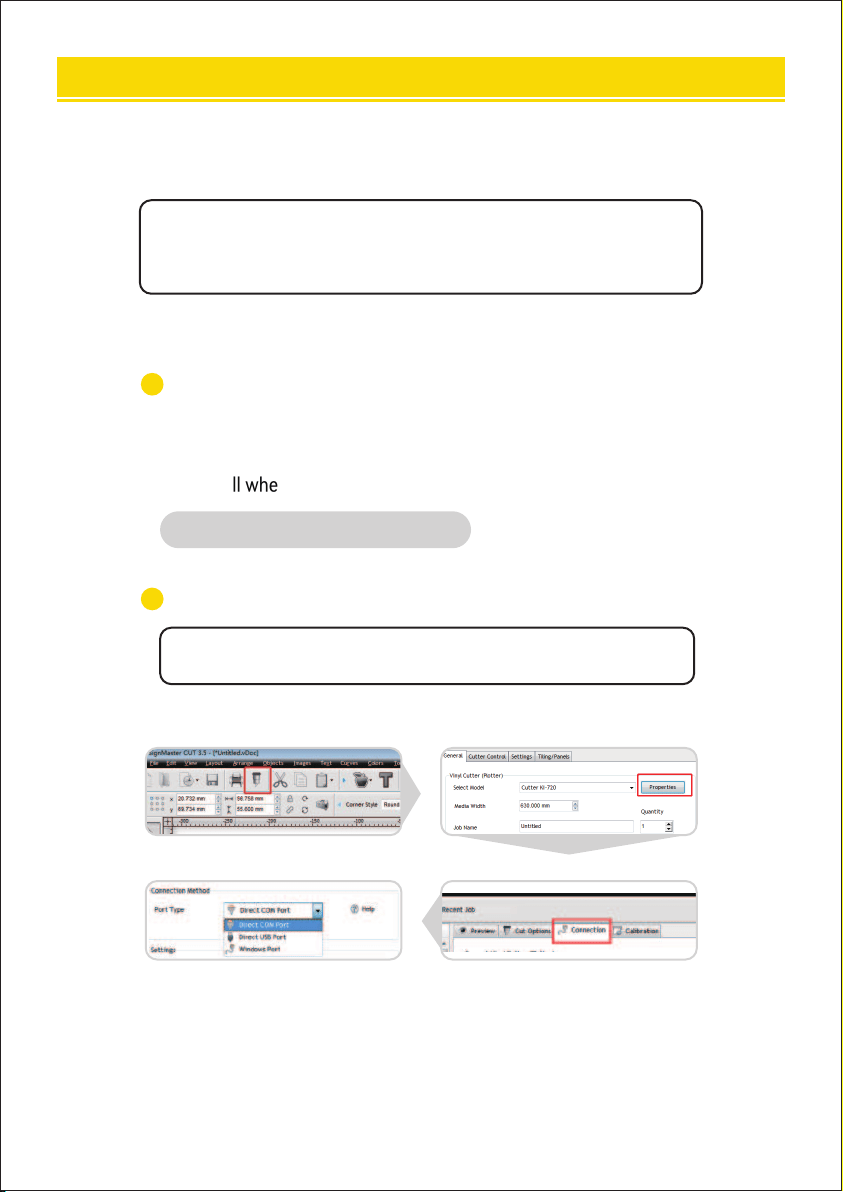
The product cannot be connected to the software.
Solution: Check software po settings, as shown in the following
gures.
Ⅹ. DOWNLOAD LINK OF SOFTWARE
23

The carriage is damaged and needs to be replaced.
Solution: For details, see the replacement operation guide video.
The D-typed motherboard is damaged and needs to be replaced.
Solution: For details, see the replacement operation guide video.
The inteace board is damaged and needs to be replaced.
Solution: For details, see the replacement operation guide video.
The software cannot identify the device.
Solution: When the computer is connected through a USB cable, it is normal
that the "Direct USB Po"is unavailable and turns grey.Since the machine
outputs USB-COM, the correct choice is "Direct COM Po", as shown below.
4
5
6
3
24

Tel: 855-385-1880
E-mail: CustomerSeice@vevor.com