
1
Contents
Ⅰ.Precautions…………………………………………………............................2
Ⅱ. Introduction for main parts………………..............................…....3-5
Ⅲ. Technical parameters………….…................................................6-7
Ⅳ. Bracket assembly diagram……..………….................................….8-10
Ⅴ. Control buttons description and operation instructions………11
Ⅵ. Blade assembly….....................................................................12-13
Ⅶ. Software and driver installation…............................................14-19
Ⅷ. Connection of software and machine…...................................20-24

2
Ⅰ.Precautions
1. Protective material must be removed before turning on the cutting plotter.
2. Check the label on the back side of the plotter to confirm that the rated
voltage required by the plotter matches the voltage of the power base.
3. Firstly make sure that the power switch is off, then plug the power supply
into grounded power outlet.
4. Please do not touch the power cord with wet hands to avoid electric shock.
5. Please only use the power cord, data cable provided with this product, or
manufacturer-approved replacements.
6. Please do not drop metal objects and liquids into the machine to avoid
malfunction.
7. After shutting down, you must wait another 5 seconds to turn on the cutting
plotter again, otherwise it will cause damage to the cutting plotter.
8. In thunderstorms, turn the power switch to OFF and unplug the power cord.
9. Please do not privately change the manufacturer's components.
10. Manufacturer reserves the right to change product specifications without
prior notice.
11. The manufacturer only bears the legal obligations of the product itself sold
to the users, and does not bear other losses caused by the malfunction of
the products.
12. Without our company’s permit, no part of this manual can be copied or
transmitted in any name.
3
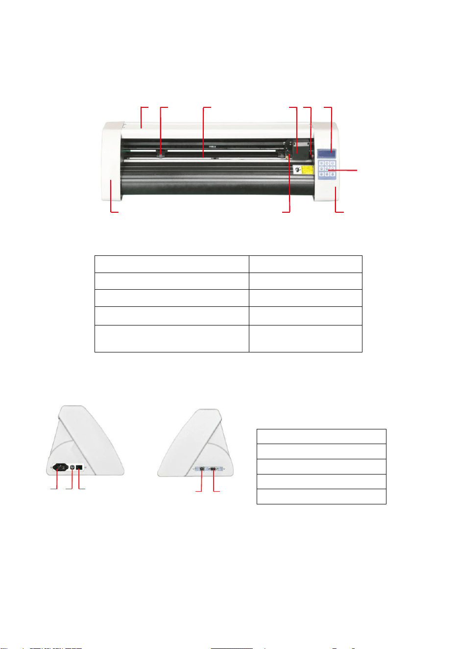
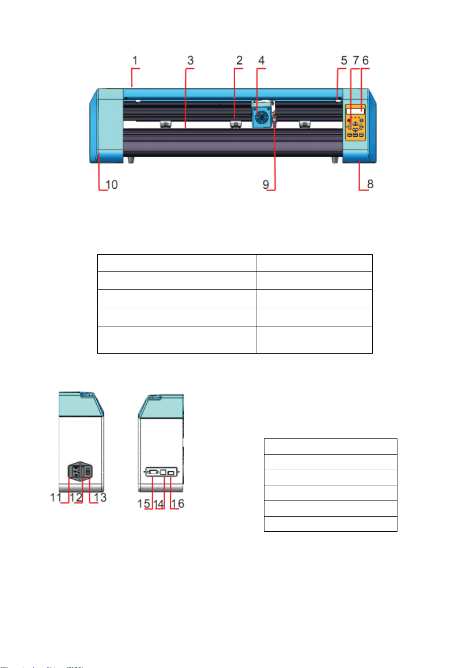
Ⅱ. Introduction for main parts
21 3 4 5 6
7
8901
KH Model
Left side Right side
1.Cover for rail guide
2. Pinch roller kit
3. Roller for feeding paper
4. Carriage
5. Reset switch
6. Screen
7. Buttons
8. The right cover
9. Blade clamp
10. The left cover
11.Power connection
12.Fuse holder
13.Power switch
14.USB port
15.COM port
11 12 1
3
14 1
5
4
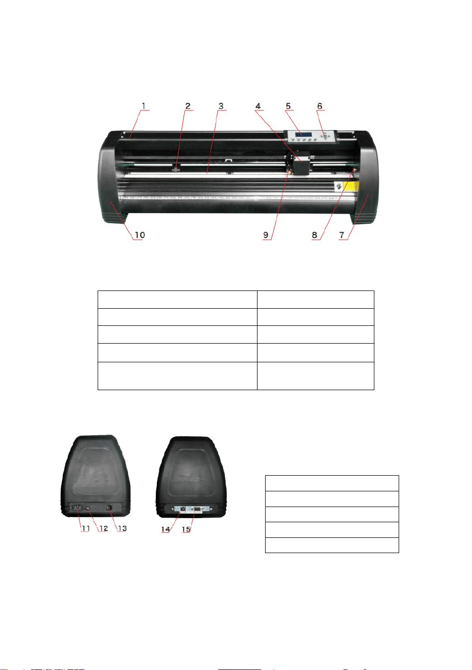
KI Model
Left side Right side
1.Cover for rail guide
2. Pinch roller kit
3. Roller for feeding paper
4. Carriage
5. Screen
6. Buttons
7. The right cover
8. Reset switch
9. Blade clamp
10. The left cover
11.Power connection
12.Fuse holder
13.Power switch
14.USB port
15.COM port
5
EH Model
Left side Right side
1.Cover for rail guide
2. Pinch roller kit
3. Roller for feeding paper
4. Carriage
5. Reset switch
6. Screen
7. Buttons
8. The right cover
9. Blade clamp
10. The left cover
11.Power connection
12.Fuse holder
13.Power switch
14.USB port
15.COM port
16.U-disk port

6
Ⅲ. Technical parameters
Model
Item
375
720
870
1350
Max. feeding width
375mm
720mm
870mm
1350mm
Max. cutting width
285mm
630mm
780mm
1260mm
Cutting thickness
≤1mm
Speed/Pressure
20-1200mm/s 20-1000g
Buffer
1-4M
LCD display
CN/EN
Real-time
Speed adjusting
Support
Interface
COM+USB / COM+USB+U-DISK
Re-cutting function
Support
Re-cutting accuracy
0.127mm
Resolution Ratio
0.0245mm/step
Language format
DMPL/HPGL
Voltage
AC85-264V

7
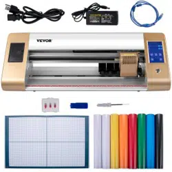
Accessory box
Item
Quantity
Unit
1
Cutting plotter
1
Set
2
Power supply cable
1
Pc
3
Blade
1
Box
4
Blade holder
1
Pc
5
Pen holder
1
Pc
6
Ball pen core
1
Pc
7
COM connection cable
1
Pc
8
USB cable
1
Pc
9
Spanner
1
Pc
10
USB driver
1
Pc
11
Bracket screws
1
Bag
To protect the machine, use only the accessories in this
accessory box
8
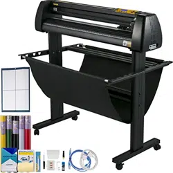
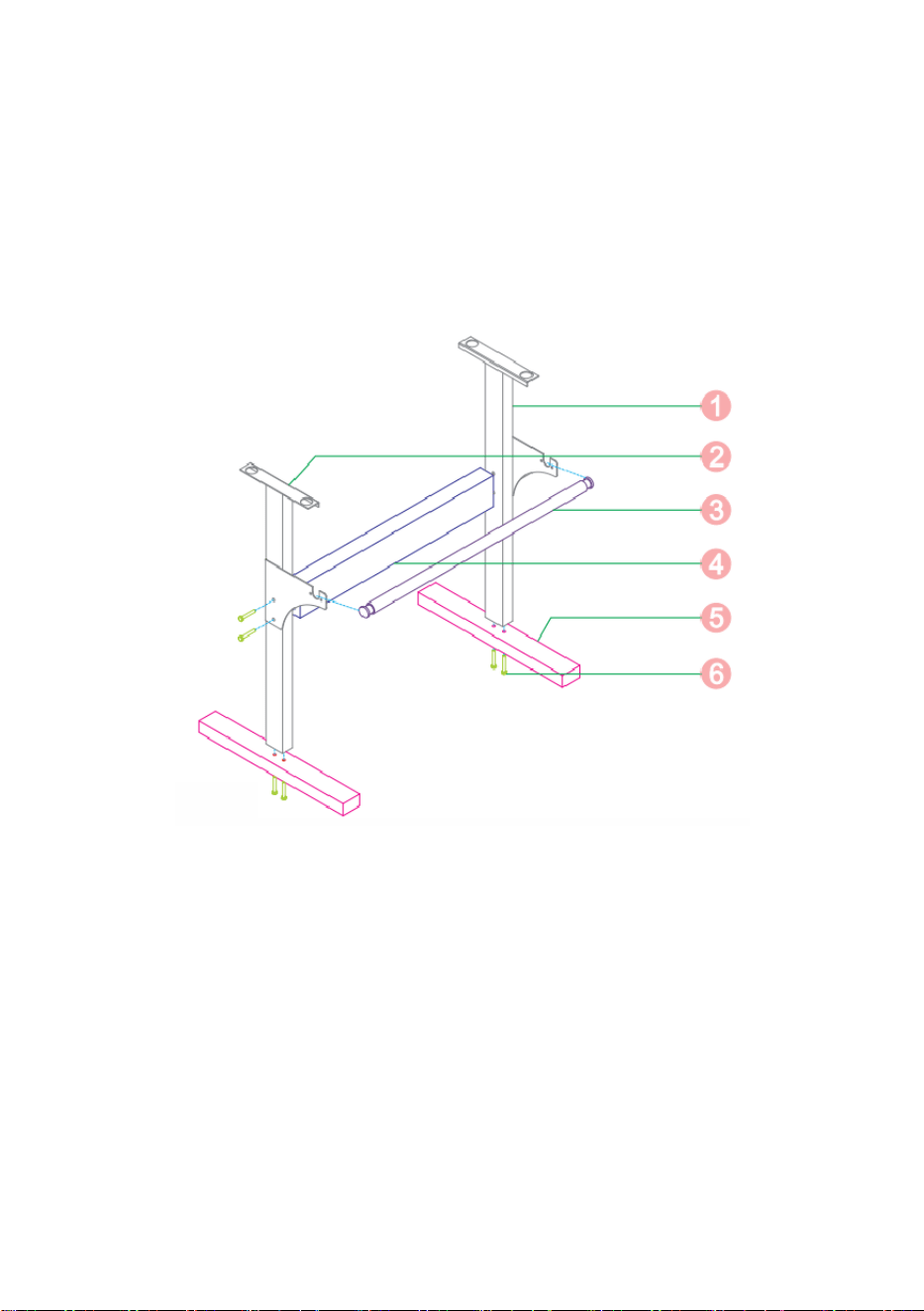
Ⅳ. Bracket assembly diagram
Iron bracket assembly diagram
1. Right column 1pc
2. Left column 1pc
3. Paper roller 1pc
4. Beam 1pc
5. Foot 2pcs
6. M6*40 Hex bolts 8pcs

9
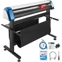
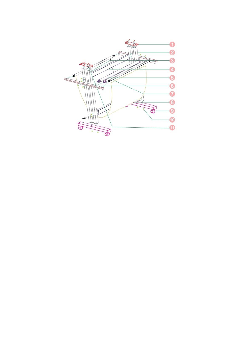
Al bracket assembly diagram
1. Left column 1pc
2. Beam 1pc
3. Paper roller 2pcs
4. Right column 1pc
5. Paper holder 2pcs
6. Foot 2pcs
7. Screws 6 sets
8. Screw sleeve 4 sets
9. Self-tapping screw 4*16 4pcs
10. Self-tapping screw 4*40 8pcs
10
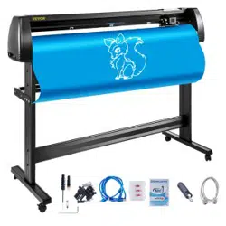
Sheet metal racket assembly diagram
1. Connected board 2pcs
2. Right column 1pc
3. Left column 1pc
4. Beam 2pcs
5. Paper roller 2pcs
6. Paper holder 2pcs
7. Basket roller 2pcs
8. Basket 1pc
9. Foot 2pcs
10. 5×10 Socket head cap screw 20pcs
11. 4×6 Flat head screw 8pcs
11
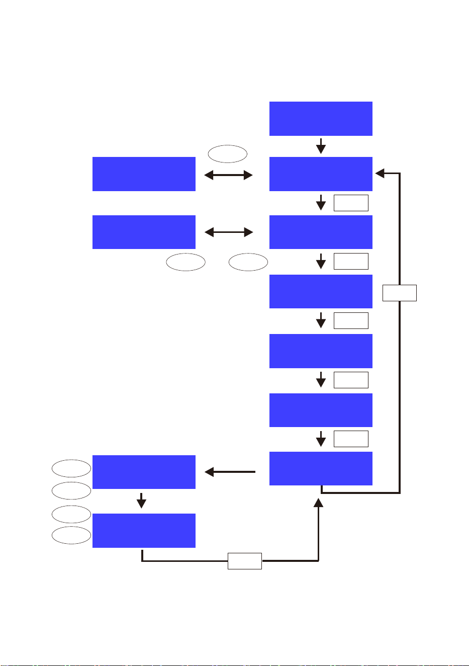
Ⅴ. Control buttons description and operation instructions
Welcome
Speed 800mm\s
Setlanguage
Laser
Force 105g
Chinese
X scale 10000
Y scale 10000
Virtual COM N
Printer Y
SD fi le
NO SD
X= 0
Y= 0
S e tti ng La nguag e
ENGLISH
OFFINE
V+
V
-
or
SETUP
SETUP
SETUP
SETUP
SETUP
SETUP
F-
V
-
ORIGIN
X-Delt: + 0
Y-Delt: + 0
X-Delt: + 20
Y-Delt: + 30F
+
V+
12
Ⅵ. Blade assembly
1). Assembly the blade into holder, see as below:
(Appearance view) (Exploded view)
2). Loosen the blade adjustment nut and rotate the shank to adjust the
length of the exposed blade tip. Determine the tip length according to
the thickness of the material.
Correct Blade tip is too long Blade tip is too short

13
1) Press the pressing rod when you want to change blade. Take out
the blade when it is exposed.
2) Assembly the blade holder into wagon:
a, Loosen the fixed screw on tool holder
b, Put the blade holder into tool holder
c, Tighten and fix the blade holder when it arrives to correct
position
Tips:
Do not touch the blade tip by finger,
otherwise, your finger will be injured and the
tip will be blunt.
14
Ⅶ. Software and driver installation
1. Open the software box (pic 1), take the disk and put
it into CD optical drive (pic 2)
(pic 1) (pic 2)
2.Open the computer, double click or right click optical drive to install
the software. (pic 3)
(pic 3)
15
1
3. After opening optical driv e, click Install Software (pic 4)
Click on the icon in the red box Select the language
(pic 4-2)
(pic 4-1)
Enter the PSN code Agreeto click next
(pic 4-3)
(pic 4-4)
16
Default installation path, click next
(pic 4-5)
Select the unit
FFI
(pic 4-6)
17
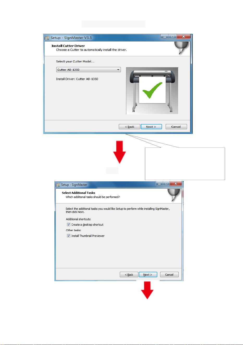
Select machine model
(pic 4-7)
(
(pic 4-7)
Next
(pic 4-8)
The selected machine
model can be viewed
in the label above the
machine power socket
18
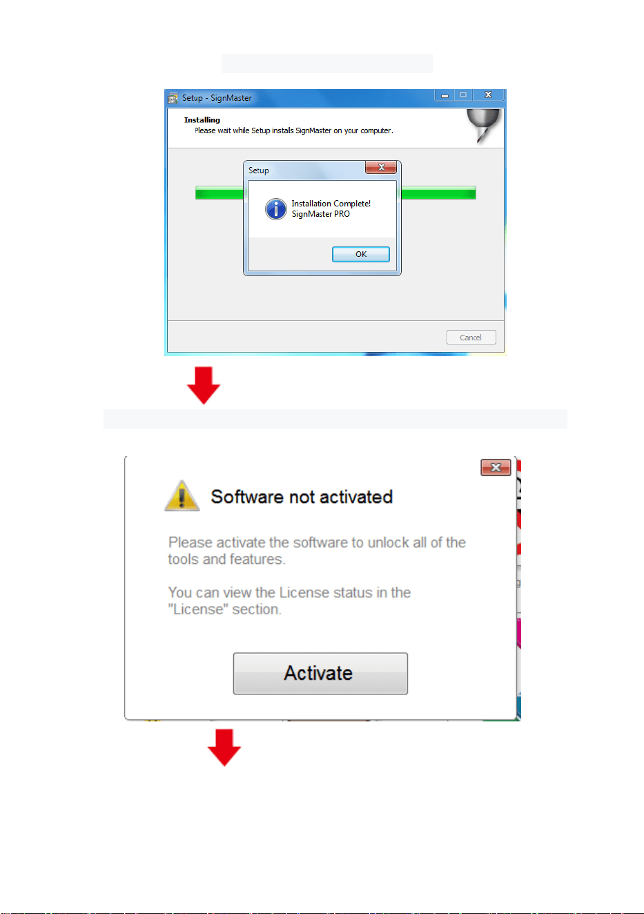
The installation is complete
(pic 4-9)
This activation window appears when you open the software
(pic 4-10)
19
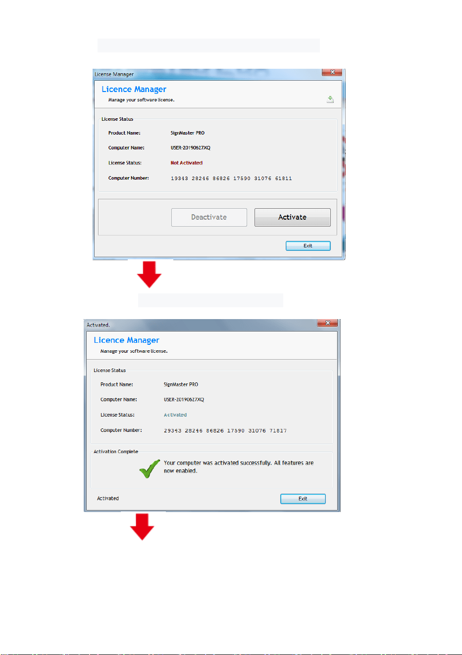
Click activate and enter your email twice
(pic 4-11)
Activation successful, exit
(pic 4-12)
20
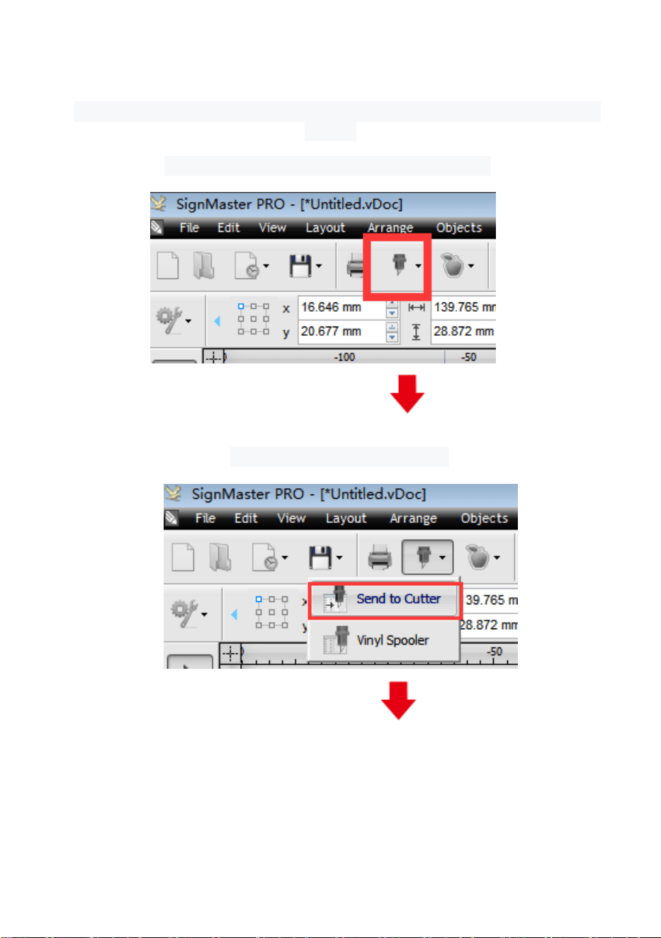
Ⅷ. Connection of software and machine
1.Open the software, select cut content, and click send to the cutting
plotter
Click the carving knife icon in the red box
(pic 5-1)
Click send to cutting plotter
(pic 5-2)
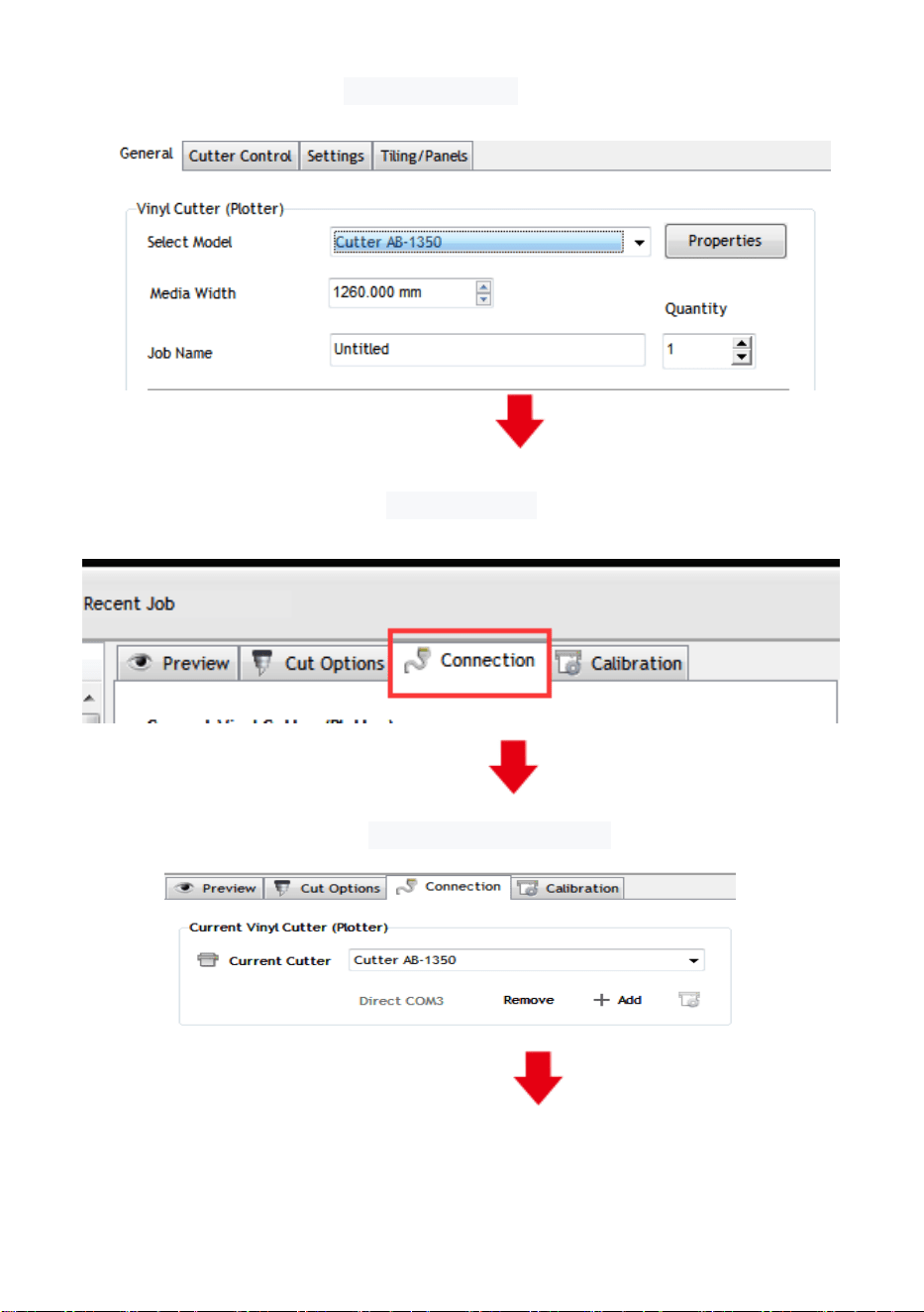
21
Click properties
(pic 5-3)
Click connect
(pic 5-4)
Select machine model
(pic 5-5)
(pic 5-5)
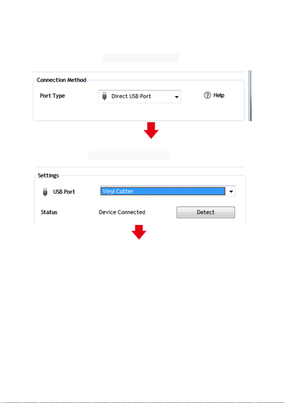
22
Select Direct USB Port
(pic 5-6)
Drop-down select driver
(pic 5-7)
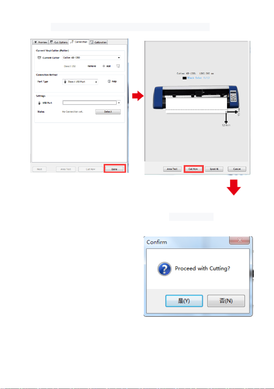
23
Click finish Click cut now
(pic 5-8) (pic 5-9)
Click cut now
(pic 5-10)

24
The output is completed, the cutting plotter is cutting
(pic 5-11)
Note: Please refer to the USB flash drive for specific operation, including
the following videos
1. Ordinary cutting video
2. Automatic contour video
3. Automatic deviation correction video
4. Software installation video