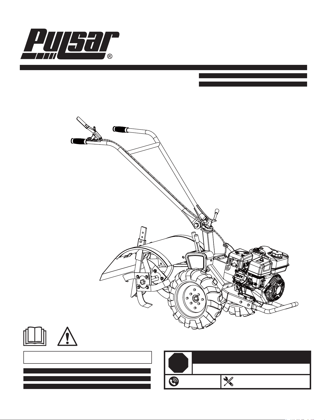
Model#PTG1120RG
Gear Drive Tiller
OPERATOR’S MANUAL
Warning: The Engine Exhaust from this product contains chemicals known to
the State of California to cause cancer, birth defects or other reproductive harm.
support@pulsar-products.com
866-591-8921
STOP
DO NOT RETURN TO STORE!
HAVE QUESTIONS OR NEED SERVICE?
Table of Contents
Safety Information ................................. . 2
Pre-Assembly ..................................... . 6
Planning Assembly .............................. . . 6
Tools Required ................................... . 6
Hardware Included ................................ . 6
Package Contents ................................ . 6
Operation ... .................................. . . . .10
Maintenance . ..................................... .16
Care, Cleaning and Storage ......................... . . . .19
Troubleshooting ................. ................ . . 20
Service Parts .......................................21
Safety Information
GENERAL SAFETY
Read this operator’s manual carefully in its entirety before
attempting to assemble this machine. Read, understand,
and follow all instructions on the machine and in the
manual(s) before operation. Keep this manual in a safe
place for future and regular reference and for ordering
replacement parts.
□
□
□
□
□
□
□
□
□
□
□
□
DANGER: Indicates an imminently hazardous situation
which, if not avoided, will result in death or serious injury.
WARNING: Indicates a potentially hazardous situation
which, if not avoided, could result in death or serious injury.
CAUTION: Indicates a potentially hazardous situation
which, if not avoided, may result in minor or moderate injury.
IMPORTANT: Indicates operation or maintenance
information which is important but not hazard-related.
NOTICE: Indicates a practice not related to personal injury which,
if not avoided, may result in property damage.
Be completely familiar with the controls and the proper use
of this machine before operating it.
This machine is a precision piece of power equipment.
Therefore, exercise extreme caution at all times.
Regularly inspect the tiller. Make sure parts are not bent,
damaged, or loose.
Use this equipment for its intended purpose only.
Operate the unit only with guards, shields, and other safety
items in place and working correctly.
Service the unit only with authorized or approved replacement
parts.
Complete all unit maintenance and adjustments according to
the instructions in this manual.
To prevent accidental starting when setting up, transporting,
adjusting or making repairs, always disconnect spark plug
wire.
Be thoroughly familiar with the controls and the proper use
of the tiller before starting. Know how to stop the engine
quickly.
To help avoid tiller tines contact or a thrown object
injury, stay in operator zone behind handles and keep
children, bystanders, helpers and pets at least 75 feet from
tiller while it is in operation. Stop machine if
anyone enters area.
Always wear safety glasses or safety goggles during
operation and while performing an adjustment or repair
to protect your eyes. Thrown objects which ricochet can
cause serious injury to the eyes.
Wear sturdy, rough-soled work shoes and close-fitting
pants and shirts. Shirts and pants that cover the arms
and legs and steel-toed shoes are recommended. Never
operate this machine while barefoot, in sandals, slippery
or lightweight (e.g. canvas) shoes.
Assembly ... ................................... . . . . 7
2

Safety (continued)
GENERAL SAFETY
□
□
□
□
□
□
□
□
□
□
□
□
□
□
□
□
□
□
□
□
□
□
□
□
□
□
□
□
Do not put hands or feet near or under rotating parts. Keep
clear of discharge area at all times as the rotating tines
can cause injury.
Never operate the tiller without proper shields,
guards, control lever or other safety protective devices in
place and working.
Never operate the tiller with damaged safety devices.
Failure to do so, can result in personal injury.
Familiarize yourself with all the safety and operating decals
on this equipment.
Thoroughly inspect the area where the tiller is to be used
and remove all foreign objects. Your equipment can propel
small objects at high speed causing personal injury or
property damage.
Check that all nuts and bolts are tight and equipment is in
good condition before each use.
Never allow children or young teenagers to operate the tiller.
Only allow responsible individuals, who are familiar with the
instructions, to operate the tiller.
Do not operate the tiller while under the influence of alcohol
or drugs.
The control lever is a safety device. Never attempt to
bypass its operation. Doing so makes the safety device
inoperative and may result in personal injury through
contact with the rotating tines. The control lever
must operate easily in both directions and automatically
return to the disengaged position when released.
Do not put hands or feet near or under rotating parts.
Operate only in daylight or good artificial light. Walk, never
run.
Exercise extreme caution when operating on or crossing
gravel drives, walks, or roads. Stay alert for hidden hazards
or traffic.
Exercise caution to avoid slipping or falling. Always be sure
of your footing; keep a firm hold on the handle and walk;
never run. Never operate the tiller at high transport speeds
on slippery surfaces.
If the equipment should start to vibrate abnormally, stop
the engine and check immediately for the cause. Vibration
is generally a warning of trouble.
Never leave the tiller unattended when the engine is running.
Stop the engine and make sure all moving parts have
stopped. Remove the wire from the spark plug.
Muffler and engine become hot and can cause a burn. Do
not touch.
Do not run the engine indoors or inside a closed area. The
exhaust fumes are dangerous, containing CARBON
MONOXIDE, an ODORLESS AND DEADLY gasoline.
Watch for holes, roots, bumps, or other rough ground. Tall
grass can hide obstacles.
Always look behind and down and use caution when using
reverse or pulling the tiller towards you.
Never attempt to start the tiller unless both wheels are in the
locked position. This acts as a brake for the tiller.
Always start the tiller on the level surface.
Only use parts and accessories made for this machine by
the manufacturer. Failure to do so can result in personal
injury.
When starting engine, pull cord slowly until resistance
is felt, then pull rapidly. Rapid retraction of starter cord
(kickback) will pull hand and arm toward engine faster than
you can let go. Broken bones, fractures, bruises or sprains
could result.
Disengage clutch lever and stop engine before leaving the
tiller in operating position. Wait until the tines come to a
complete stop before removing debris or making any
adjustments to the tiller.
Do not attempt to till hard soil, till too deep or till at too fast
a rate that can overload the tiller.
Gasoline is extremely flammable, and gasoline vapors can
explode if ignited. Handle with care.
Use an approved container.
3

Safety (continued)
GENERAL SAFETY
□
□
Tragic accidents can occur if the operator is not alert to the
presence of children. Children are often attracted to the tiller.
They do not understand the dangers. Never assume that children
will remain where you last saw them.
□
□
□
□
□
□
□
□
□
Always be sure of your footing. A slip and fall can cause
serious personal injury. If you feel you are losing your
balance, release the control lever immediately and the
tine will stop rotating.
Do not till near drop-offs, ditches or embankments, you
could lose your footing or balance.
Keep children out of the tilling area and under watchful
care of a responsible adult other than the operator.
Be alert and turn tiller off if a child enters the area.
Before and while moving backwards, look behind and
down for small children.
Use extreme care when approaching blind corners,
doorways, shrubs, trees, or other objects that may obscure
your vision of a child who may run into the tiller.
Keep children away from hot or running engines. They can
suffer burns from a hot muffler.
Never allow children to operate this machine.
To avoid personal injury or property damage use extreme
care in handling gasoline. Gasoline is extremely flammable
and the vapors are explosive. Serious personal injury can
occur when gasoline is spilled on yourself or your clothes,
which can ignite. Wash your skin and change clothes
immediately.
Use only an approved gasoline container.
Never fill containers inside a vehicle or on a truck or trailer
bed with a plastic liner. Always place containers on the
ground away from your vehicle before filling.
CHILDREN SAFETY
□
□
□
□
□
□
□
□
□
□
□
□
□
Remove
gasoline-powered equipment from the truck or
trailer and refuel it on the ground. If this is not possible,
then refuel such equipment on a trailer with a portable
container, rather than from a gasoline dispenser nozzle.
Keep the nozzle in contact with the rim of the fuel tank or
container opening at all times until fueling is complete. Do
not use a nozzle lock-open device.
Extinguish all cigarettes, cigars, pipes and other sources
of ignition.
Never fuel machine indoors because flammable vapors will
accumulate in the area.
Never remove
gasoline
cap or add fuel while engine is hot
or
running. Allow engine to cool at least two minutes before
refueling.
Never over fill fuel tank. Fill tank to no more than 1 inch
below bottom of filler neck to provide for fuel expansion.
Replace gasoline cap and tighten securely.
If gasoline is spilled, wipe it off the engine and equipment.
Move machine to another area. Wait 5 minutes before
starting engine.
Never store the machine or fuel container near an open
flame, spark or pilot light as on a water heater, space
heater, furnace, clothes dryer or other
gasoline
appliances.
To reduce fire hazard, keep machine free of grass, leaves,
or other debris build-up. Clean up oil or fuel spillage and
remove any fuel soaked debris.
Allow machine to cool at least 5 minutes before storing.
Never run an engine indoors or in a poorly ventilated area.
Engine exhaust contains carbon monoxide, an odorless and
deadly gasoline.
If situations occur which are not covered in this manual,
use care and good judgement. Contact Customer Support
for assistance or the name of the nearest service dealer.
SAFETY WHILE SERVICING
Safe Handling Of Gasoline:
4

Safety (continued)
GENERAL SAFETY
□
□
□
□
□
□
□
□
□
□
□
Before cleaning, repairing, or inspecting, make certain the
tines and all moving parts have stopped. Disconnect the
spark plug wire and ground against the engine to prevent
unintended starting.
Check the tines and engine mounting bolts at frequent
intervals for proper tightness. Also, visually inspect tines
for damage. Replace with the original equipment
manufacture’s (O.E.M.) parts only, listed in this manual.
“Use of parts which do not meet the original equipment
specifications may lead to improper performance and
compromise safety!”
Keep all nuts, bolts, and screws tight to be sure the
equipment is in safe working condition.
Never tamper with safety devices. Check their proper
operation regularly.
After striking a foreign object, stop the engine, disconnect
the spark plug wire and ground against the engine.
Thoroughly inspect the tiller for any damage.
Repair the damage before starting and operating the tiller.
Tiller components, guards and shields are subject
to wear and damage which could expose moving parts
or allow objects to be thrown. For safety protection,
frequently check components and replace immediately
with original equipment manufacturer’s (O.E.M.) parts only,
listed in this manual. “Use of parts which do not meet the
original equipment specifications may lead to improper
performance and compromise safety!”
Do not change the engine’s governor setting or over-speed
the engine. The governor controls the maximum safe
operating speed of the engine.
Check fuel line, tank, cap, and fittings frequently for cracks
or leaks. Replace if necessary.
Do not crank engine with spark plug removed.
Maintain or replace safety and instruction labels, as
necessary.
Observe proper disposal laws and regulations. Improper
disposal of fluids and materials can harm the environment.
Do not modify engine.
□
To avoid serious injury or death, do not modify engine in any
way. Tampering with the governor setting can lead to a
runaway engine and cause it to operate at unsafe speeds.
Never tamper with factory setting of engine governor.
WARNING: This machine is equipped with an internal
combustion engine and should not be used on or near any
unimproved forest-covered, brush covered or grass-covered
land unless the engine’s exhaust system is equipped with a
spark arrestor meeting applicable local or state laws (if any).
5
Pre-Assembly
PLANNING ASSEMBLY
Place box on a level suace. Remove all items from box. Make sure all items listed on the package contents list are included and not
damaged.
TOOLS REQUIRED
wrench
了 Funnel
HARDWARE INCLUDED
色 NOTE: Hardware not shown to actual size.
冒
—
AA
—
BB
V
—
cc
(
—
DD
勹
—
EE
�
—
F
f
©
—
GG @
—
HH
@
—
“心
—
JJ 飞
—
KK
—
LL
—
MM
Pa
Description
Quantity
Bolt M8x20
8
BB
Nut MB
6
cc
Bolt M16x140
1
DD
Up/Down Lever Lock
1
EE
Clevis Pin中8x30
1
FF
Coer Pin
5
GG
Washer
4
PACKAGE CONTE
NTS
Pa
Description
Quantity
HH
Spring Washer
4
II
Armrest Spring Washer
4
JJ
Armrest
1
KK
LeRight Handle Lock
1
LL
Clevis Pin 中 8x45
4
MM
Cable Clip
1
Pa
Description
Quanti
A
Tiller Bod
y
/Upper Handle 1
B
Wheel
2
C
Depth Regulator
1
D
Tiller Protective Shield
1
Pa
Description
Quanti
E
Tines
2
F
Bumper
1
G
Use And Care Guide
1
6
Assembly
Assembling the Depth Regulator
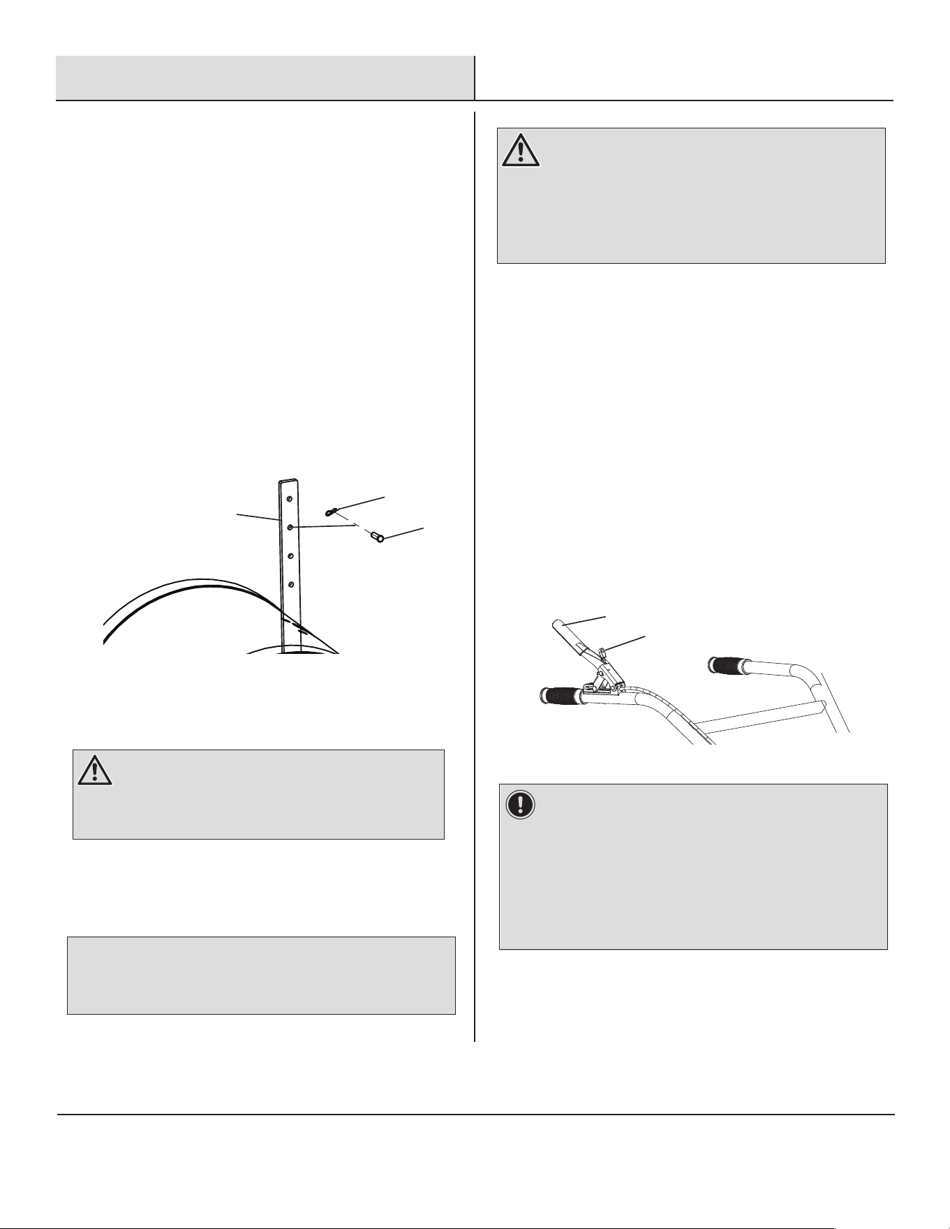
□
□
Insert the depth regulator (C) through the protective
shields (D) opening into the top of the depth regulator
bracket with handle facing to the rear.
Insert depth regulator clevis pin (EE) through the depth
regulator bracket. Then insert the cotter pin (FF) to secure.
The top hole of the depth regulator tines should clear
the ground. See Figure 1-1.
□ Locate the plates with the pre-drilled holes on the rear part
of the tiller body. Align the protective shield (D) holes to the
plate holes. Insert M8x20 bolts (AA) with spring washers
(HH) and regular washers (GG) and tighten with a wrench.
The front plate requires two M8 nuts (BB) to secure.
See Figure 1-2.
3
1
Assembling the Protective Shield to
the Tiller Body
2
Assembling the Handle
The handle is attached to the tiller body when shipped by the throttle
cable only. You will need secure the handle following the next few steps.
□
□
NOTICE: This tiller is shipped without gasoline or oil in the engine.
Fill up the gasoline and oil BEFORE operating your machine.
Figure 1-1
Figure 1-2
C
FF
EE
Depth Regulator
Bracket
D
Tiller Body
Handle
DD
KK
JJ
II
CC
D
AA
HH
HH
BB
HH
GG
AA
AA
GG
GG
WARNING: Make sure the tiller protective shield is
installed in place before starting the machine.
Insert the armrest (JJ) to the bolt seated on the tiller frame.
Then insert the armrest spring washer (II) and hand tighten with
handle lock (KK).
Align handle openings over the armrest openings and insert
bolt M16x140 (CC) through the handle and armrest. Use the
handle lever lock (DD) to secure on the opposite side. Use a
wrech on the M16x149 bolt (CC) to hold the bolt in place while
you hand tighten the handle lever lock (DD) on the opposite side.
See Figure 1-3.
Figure 1-3
7
Assembly (continued)
Assembling the Wheels
4
Assembling the Tines
6
Assembling the Bumper
5
Figure 1-5
L
R
Tiller Body
AA
BB
F
Figure 1-4
Figure 1-6
Tiller Body
B
B
FF
FF
Insert tines (E) on each side through the tine axle located on the
rear of the tiller. Align pre-drilled holes and insert clevis pin (LL)
then insert cotter pin (FF) to secure in place. See Figure 1-6.
WARNING: Make sure to install the wheel in the
correct direction. See Figure 1-4.
□
Insert the wheel (B) through the axle on the tiller body. Then
place the clevis pin (LL) through the hole on the wheel
through the axle to secure the wheel in place. Place the
cotter pin (FF) to lock in place. See Figure 1-4.
□
Insert the bumper (F) into the front end of the tiller body
just below the engine. Align the pre-drilled holes and
insert M8x20 bolts (AA) and M8 nuts (BB) and tighten.
See Figure 1-5.
□
E
8
Assembly (continued)
Check Tire Pressure
7
(Models with pneumatic tires) Check the air pressure in
both tires before each use. The air pressure should be
between 25 PSI and 30 PSI (pounds per square inch).
If the air pressure is lower than 25 PSI, inflate the tires air
pressure with air pump.
Keep both tires equally inflated to help prevent machine
from pulling to one side.
□
□
□
Figure 1-7
9
Operation
Adding Gasoline and Oil
□
□
□
□
□
Place the tiller on a level surface.
Remove the filler cap. Place the funnel securely and add oil.
Do not top off. Oil capacity is approx. 0.6 liters. Check
dipstick to confirm adequate amount of oil.
Secure the oil cap and wipe off any excess oil.
See Figure 1-9.
1
WARNING: Use extreme care when handling gasoline.
Gasoline is extremely flammable and the vapors are
explosive. Never fuel the machine indoors or while the
engine is hot or running. Extinguish cigarettes, cigars,
pipes and any other sources of ignition.
IMPORTANT: Use only Regular Octane Fuel.
Figure 1-8
Figure 1-9
104
86
68
50
32
14
-4
-22
40
30
20
10
0
-10
-20
-30
°C°F
SAE 30
10W-30
SYNTHETIC 5W-30
5W-30
GAS
□
□
□
We recommend the use of 10W-30 oil. Other high-quality
detergent oils are acceptable if classified for service SF, SG,
SH, SJ or higher.
Do not use special additives.
Outdoor temperatures determine the proper oil viscosity for
the engine. Use the chart to select the best
viscosity for the outdoor temperature range expected.
IMPORTANT: We recommend using 10W-30 Oil.
OIL
Remove gasoline cap. Place funnel securely and add
fuel. Do not top off. Fuel tank capacity is approx. 0.9
gallon.
Secure the gasoline cap and wipe off any excess
fuel. See Figure 1-8
10
Operation (continued)
Controls and Features
RECOIL STARTER
PROTECTIVE SHIELD
CLUTCH
□
□
The recoil starter is attached to the right side of the upper
handle. Stand behind the unit and pull the recoil starter
rope to start the unit.
The tiller shield is located in the rear of the tiller and
it is used to shield you from debris being thrown.
□
The throttle lever starts the tiller forward or reverse function
depending on what gear the tiller is on. The safety lock
ensures that when using the tiller the operator does not
accidently start the forward or reverse action until they are
ready to operate the tiller.
ON/OFF SWITCH
□
The On/Off switch is needed to start and stop the tiller.
2
DEPTH REGULATOR
TINES
CHOKE LEVER
□
□
In hard compacted soil, it helps restrain the tiller's forward
motion. In looser soil, it controls how deeply the tines can dig
into the ground.
Tines are rotating metal blades that dig into the soil.
□
A carburetor choke lever engages or disengages the choke,
subsequentially adjusting the amount of air that is enabled
to flow through the intake of the carburetor.
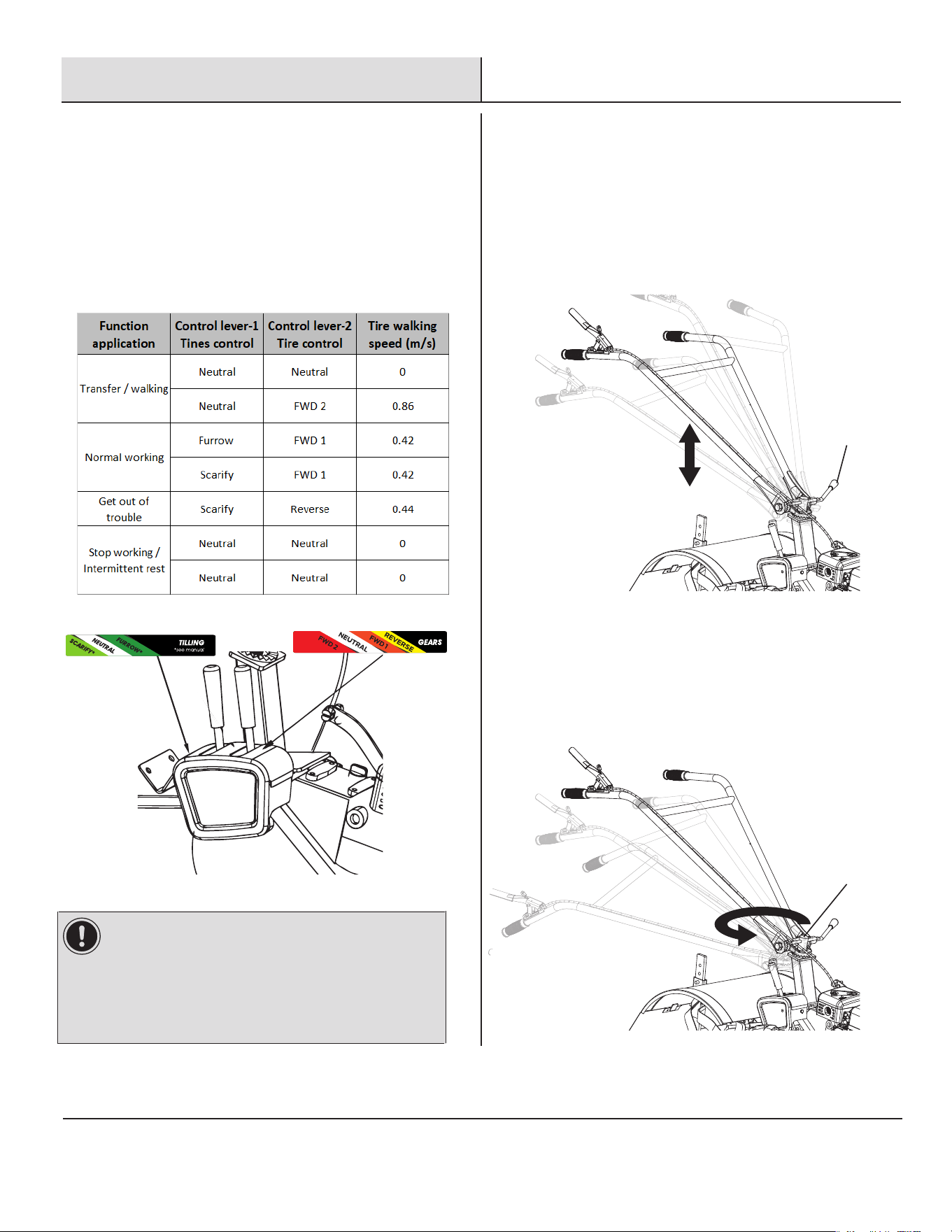
GEAR LEVERS
□
The tiller gear box is mounted on the tiller frame. One lever
controls 1st, 2nd and reverse gears. The other lever controls
the function of tilling on the soil. The 2 functions are scarify
and furrow.
1st, 2nd and Reverse Gear Lever
Clutch
Safety Lock
Depth Regulator
Protective
Shield
Tines
Choke Lever
On/Off Switch
Recoil Start
Scarify and Furrow Gear Lever
11
Operation (continued)
Pre-Start Inspection
□
□
□
□
□
□
□
□
□
Make sure all safety guards are in place and all nuts and
bolts are secure.
Check oil level in engine crankcase. Add oil if necessary.
Check the fuel supply. Fill the fuel tank no closer
than 1 inch from top of tank to provide space for
expansion.
This tiller already comes with the proper amount of
Transmission Gear Oil. Check Transmission Gear Oil
before starting if you notice a leak.
Be sure the spark plug wire is attached and the spark
plug is tightened securely.
Check position of wheels and wheel lockouts.
Check depth regulator lever position.
Examine underneath and around engine for signs of
oil or fuel leaks.
Inspect fuel hoses for tightness and fuel seepage. Look
for signs of engine damage.
Remove excessive debris from muffler area and
recoil starter.
Always set the wheels in tilling position before starting
engine.
Always put depth regulator lever in the transport position
before starting engine. Tines should clear ground.
□
□
□
□
□
□
□
□
□
The controls required to start and run the tiller are located
on the engine and are marked with the icon for choke, slow
and fast for the throttle, and on/off fuel valve. Location for
these controls can be found on the controls and features
page.
COLD STARTS
Move the fuel lever to the “open” position.
Move the choke lever to the full “Closed” position.
Move the On/Off switch to the “On” position.
Pull starting rope out slowly one time and allow to return
slowly.
Pull starting rope out rapidly to start the engine.
When the engine starts, gradually move choke lever to the
“Open” position and increase throttle speed.
RESTARTING A WARM ENGINE
Move the On/Off switch to the “On” position.
Pull the starter grip lightly until resistance is felt then pull
rapidly until engine starts. Allow rope to return normally.
Repeat until engine starts.
3
WARNING: Gasoline is highly flammable and must be
handled with care. Never fill the tank when the engine is hot
or running. Always move outdoors to fill tank.
Starting the Tiller
4
CAUTION: Please do not start your tiller until you have
read the manual that came with your tiller, and the sections
in this manual tiller controls and safety. If you have read
these, follow the steps below to start your tiller. Always
perform this pre-start checklist before starting the engine.
DANGER: Always keep hands and feet clear of rotating
machine parts.
NOTICE: Restarting an engine that is already warm from previous
running does not normally require use of the choke.
Choke
Fuel Lever
Open Closed
OPENCLOSED
On/Off Switch
□
□
□
Figure 1-10
12
Operation (continued)
Shutting Down the Tiller
□
□
To stop the engine at any time, turn engine ON/OFF switch
to the off position. To stop wheels and tines at any time,
release drive safety control levers to neutral position.
Check oil level in engine crankcase. Add oil if necessary.
Make sure you return the choke lever to it’s original
position and you close the fuel lever.
□
□
□
5
Tilling
□
□
□
Adjust the depth regulator lever to desired tilling depth.
Insert the clevis (EE) and cotter pin (FF) to secure depth
regulator to desired depth. See Figure 1-11.
6
WARNING: Temperature of muffler and nearby areas may
exceed 150˚F. Avoid these areas. Do not move choke control
to stop engine, backfire or engine damage may occur. To
stop wheels and tines at any time, release drive safety
control levers to neutral position. Always release drive safety
control levers to neutral position AND STOP THE ENGINE
before adjusting the depth of the regulator lever.
Drive Safety Control Levers
7
NOTICE: You can slow the tiller’s forward advance at any time
by putting slight downward pressure on the handlebars. You can stop
the tiller by releasing the drive safety control levers to the neutral
position.
Figure 1-2
Tiller Body
Figure
1-11
EE
FF
CLUTCH
Engages wheels and tines into forward or reverse.
Pushing down on the clutch lever toward the handlebar
engages the wheels and tines. Releasing the clutch stops
the wheels and tines and brings the tiller to a complete
stop.
To unlock the clutch handle first press the clutch lock and
then press the clutch. See Figure 1-12
Clutch
Clutch Lock
IMPORTANT: Practice operating the controls and tiller
with tines out of ground before beginning to till. It is
important that you know how to use the tiller properly,
keep control at all times, stop the tines and wheels from
turning, and stop the engine if necessary. If you do not
know how to do these things, read the controls,
adjustments and safety sections before proceeding.
Move the choke control to the closed position.
Place the tiller in forward by pushing down on the drive safety
control lever (FORWARD)--this will engage the wheels and tines.
Figure 1-12
WARNING: Raise depth regulator up one hole at a
time,testing tiller operation after each raise. Raising depth
regulator too high can result in loss of control of tiller!
13
Operation (continued)
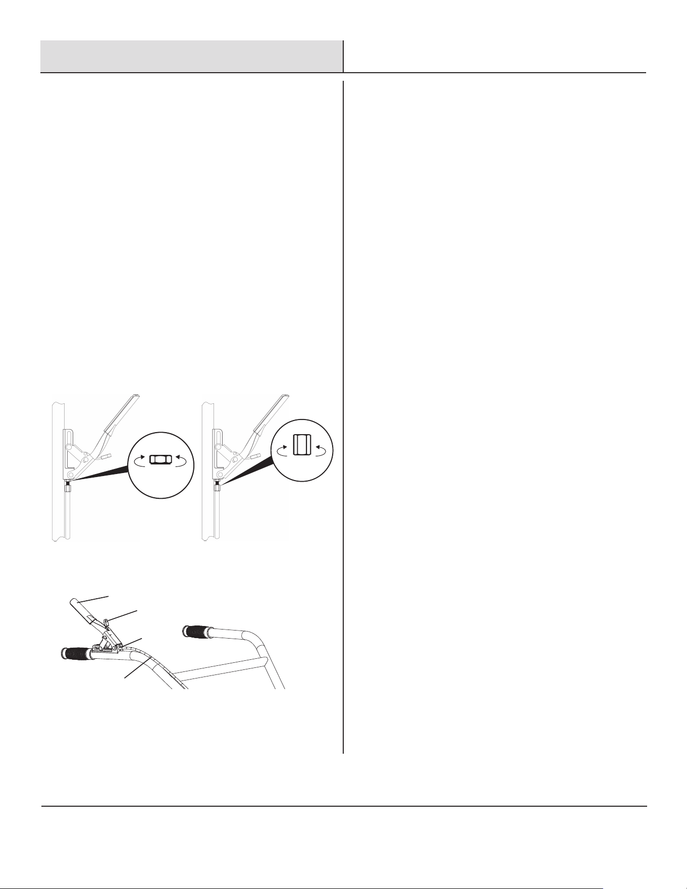
Handle Height and Left/Right
Adjustment
□
□ To adjust the handle height just loosen the up/down lever
lock (DD) and push handle up or down to the required height.
Then tighten the up/down lever lock (DD).
See Figure 1-14.
9
DD
KK
Figure 1-14
To adjust the handle axis point just loosen the left/right
handle lock (KK) and rotate the handle left or right to the
required axis point. Then tighten the left/right
handle lock (KK). See Figure 1-15.
Figure 1-15
□
(2)(1)
Figure1-13
8
The gear box is located on the tiller frame. See Figure1-13
Control Gear Box
IMPORTANT:
I. FWD 2 cannot be used at work, FWD 2 is too fast.
II. Tire control lever is "Neutral" and the blade will not
turn.
III. When using Furrow+FWD 1, you can exchange left
and right Tines for better soil turning effect.
The control method of the gear box is matched according
to the actual work needs:
□
14
Operation (continued)
Tilling Tips
□
□
□
□
□
□
□
□
11
The key to successful tilling is to begin with a shallow cut on
the first pass, and then work an inch or two deeper on each
successive pass.
Tilling depth will vary with ground conditions.
When beginning to till in unbroken ground or in extremely
hard soil, set the clevis pin in the highest hole of the depth
regulator. This will allow for shallow tilling. With the depth
regulator in this position, make several light passes over the
area to be tilled. Reset for deeper depths with successive
passes.
If tiller jumps or skids uncontrollably, lower the depth
regulator by placing the clevis pin in a higher hole. This will
allow for shallower tilling. Hold firmly to the handlebars to
control sudden lurches.
If weeds, tall grasses, vines, or other materials clog or jam
the tines, reverse the tiller to unwind vegetation.
Immediately release the drive control levers if the tines jam
or you strike a foreign object. With the drive control levers in
the neutral position, push throttle control to the stop position
to stop the engine. Disengage the spark plug wire. When
tines have stopped, remove foreign objects and check for
damage.
CULTIVATING
Plant rows on 20" - 22" centers for ease of turning.
Set the depth regulator lever with the detent pin in one
of the higher holes. This will allow for shallow cultivation
necessary to turn over weeds, and break up and aerate
the soil.
□
If operating equipment with engines regularly at altitudes over
5,000 feet, the carburetor’s air-fuel mixture will be too rich and
emmissions may increase. On engines not built for the United
States the carburetor can be adjusted to operate under this
condition. The carburetor should be returned to its normal setting
if regular operation is less than 5,000 feet. Contact your service
center to modify the carburetor.
HIGH ALTITUDE OPERATION
Clutch Cable
Jam Nut
Clutch
Clutch Lock
□
□
□
□
□
10
Wire Tension Adjustment
□
INCREASE DECREASE
TENSION TENSION
LOOSEN
(1)
(2)
TIGHTEN
Figure1-16
Proper wire tension is critical to good performance. After
1/2 hour of operation, all cables may have to be adjusted.
After using the tiller for the first time check tension after
every 2 hours of operation.
TO INCREASE WIRE TENSION
Loosen upper jam nut ⑴
Turn the adjusting nut counterclockwise in 1/8”
increments ⑵
Tighten upper jam nut ⑴
Check adjustment.
This procedure can be repeated until conduit adjustment
bolts are fully adjusted. If no more adjustment can be
made, the wire may have to be replaced. See Figure 1-16
15

Maintenance
□
□
□
□
□
□
□
□
□
□
□
□
□
□
□
□
□
□
□
□
□
□
□
□
The warranty on this tiller does not cover items
that have been subjected to operator abuse or negligence.
To receive full value from warranty, operator must
maintain the string trimmer as instructed here.
Changing of engine-governed speed will void engine
warranty.
All adjustments should be checked at least once each
season.
Periodically check all fasteners and make sure these are
tight.
Good maintenance is your responsibility, poor maintenance
is an invitation to trouble.
Follow good shop practices.
Keep service area clean and dry.
Use adequate light for the job at hand.
Make sure the engine is off before you begin any
maintenance or repairs. This will eliminate several potential
hazards.
Be sure there is adequate ventilation whenever you operate
the engine to avoid carbon monoxide poisoning.
Never operate the engine in a closed building.
Let the engine and exhaust system cool before touching.
Do not run the engine unless instructed to do so.
Read the instructions before you begin, and make sure you
have the tools and skills required.
To reduce the possibility of fire or explosion, be careful when
working around gasoline.
Use only a nonflammable solvent, not gasoline, to clean
parts. Keep cigarettes, sparks and flames away from all fuel
related parts.
Lubricate the wheels at least once a season with light oil (or
motor oil). If wheels are removed for any reason, lubricate
surface of the axle bolt and inner surface of the wheel with
light oil.
Always use personal protection devices such as eye, hand and
hearing protectors when performing any service or
maintenance.
Frequently check tiller tines. They should be free of nicks and
cracks and securely fastened in place.
Periodically tighten all bolts, nuts, screws, and check that all
pins are properly installed to make certain the tiller is safe to
operate.
When completing maintenance or service, make sure all safety
guards and devices are installed before using the tiller.
Where replacement parts are necessary for periodic maintenance
and servicing, use only new, original replacement parts or their
equivalents for repair and replacement to restore your equipment
to original specifications.
The manufacturer and/or distributor will not be responsible for
injuries or damages caused by use of unapproved parts and/or
accessories.
A first aid kit should be kept readily accessible while performing
maintenance on this equipment.
Always observe safety rules when performing any
maintenance.
16

Maintenance (continued)
□
□
Your tiller has been designed and produced by the industry’s leading manufacturer of outdoor power equipment to provide you with
years of reliable operation. Keeping your tiller in top running condition will prolong its life, and help you obtain optimum performance.
Please read this normal care schedule, and note the recommended care operating intervals to extend the life of your tiller.
*Service more frequently when used in dusty areas.
MAINTENANCE SCHEDULE
Before Each UseMaintenance Operation
Drive Wire Tension
Engine Oil
Air Filter
Tiller Transmission
Gear Oil
Tire Pressure
Tine Shaft
Wheel Axle Shaft
First
Month or
20 Hours
Every
3 Months
or
50 Hours
Every
6 Months
or
100 Hours
Every
Year or
300 Hours
Check
Change
Check Level
Change
Check
Clean
Replace
Check
Replace
Check
Clean
Lubricate
√
√
√
√
√
√
√
√
√
√* √*
√ √
WARNING: Use only genuine replacement parts. Other
parts may damage the tiller or result in injury.
17
Maintenance (continued)
□
□
□
□
□
□
□
□
□
□
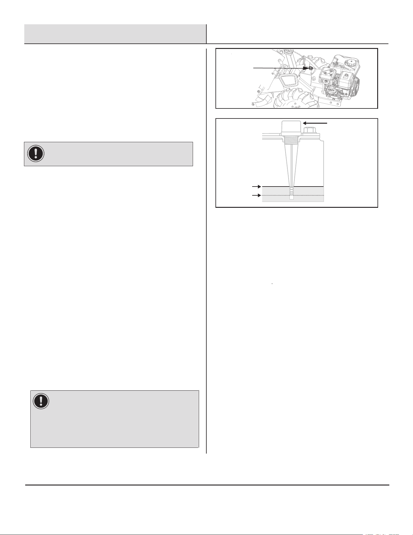
CHECK OR FILL ENGINE CRANKCASE
Add oil. Do not overfill. Use a clean, high quality detergent
oil. Do not mix oil with gasoline. Oil level must be full.
Check the oil level by removing oil fill plug. Oil level should
be up to the bottom of the fill plug opening.
Always check oil level before starting engine.
CHECK TRANSMISSION GEAR OIL
Check the transmission gear oil level after every 50 hours
of operation or whenever you notice any oil leak.
Operating the tiller when the transmission is low on oil
can result in severe damage.
To Check the Transmission Gear Oil Level:
LUBRICATION
Proper lubrication of moving mechanical parts is critical for
proper care and maintenance. Oil the moving parts shown at 10
hour intervals using a 30 weight oil.
CLEAN TINE AXLE SHAFT
Turn off engine. Engine must be cool.
Remove spark plug wire and secure from spark plug.
Tip the tiller forward. Block the tiller in position so that it rests
on the engine mount and the tines are exposed.
Remove all vegetation, string, wire, and other material that may
have accumulated on the axle between the inside set of tines
and the seal on the transmission housing.
Tip the tiller back to a level position.
Replace spark plug wire.
See Figure 1-17
IMPORTANT: Engine is shipped from factory without oil. You
must add engine oil before starting engine.
Dipstick
DIPSTICK
UPPER LIMIT
LOWER LIMIT
IMPORTANT: The tiller ships from the factory with
transmission gear oil installed. Operating the tiller
when the transmission is low on oil can result in
severe damage.Do not operate the tiller if the gear oil
level is low. Doing so will result in severe damage to
the transmission components.
□
□
1.Check the gear oil level when the transmission is cool.Gear
oil will expand in warm operating temperatures and this
expansion will provide an incorrect oil level reading.
2.With the tiller on level ground, pull the Depth Regulator Lever
all the way up.
3.Remove the dipstick/oil fill plug from the transmission
housing and look inside the oil fill hole to locate the main drive
shaft situated below the hole.
4.The gear oil level is correct if it falls between the upper limit
and lower limit marks on th oil dipstick. See Figure 1-17
5.If the gear oil level is low, add gear oil (SAE 85W-140 or
85W-90),the tiller gear case holds 122-135 ounces.Do not
overfill.
6.If the gear oil level is okay, securely replace the oil fill plug.
18
Care, Cleaning and Storage
□
□
□
□
□
□
□
□
□
□
□
□
Protect wheels and axles from rust by removing the lockpin
and sliding the wheel off the hub.
Coat the axles lightly with axle grease.
Slide wheel back on hub and insert lock pin.
Drain fuel system completely or add fuel stabilizer to prevent
fuel from gumming up during extended storage period.
While engine is still warm, drain the oil from the engine.
Refill with fresh oil of the recommended grade.
Clean external surfaces, engine and cooling fan.
Remove spark plug, pour one ounce of SAE 30 oil into spark
plug hole.
Plug hole and pull starter cord slowly to distribute oil evenly
in cylinder head area.
Reinstall spark plug.
Transport unit to a suitable storage location. If you have
chosen to use a fuel stabilizer and have not drained the fuel
system, follow all safety instructions storage precautions in
this manual to prevent the possibility of fire from the ignition
of gasoline fumes. Remember, gasoline fumes can travel to
distant sources of ignition and ignite, causing risk of
explosion and fire.
If there is any possibility of unauthorized use or tampering,
remove the spark plug and store it in a safe place before
storing the rototiller unit.
Be sure to plug the spark plug hole to prevent foreign
material from entering.
Follow the steps below to prepare your tiller for storage.
WARNING: Do not store tiller in an unvetilated area where
fuel fumes may reach flame, sparks, pilot lights or an ignited
object. Drain fuel outdoors away from any ignition sources.
Use only approved fuel containers.
19

Troubleshooting
Problem SolutionCause
The engine is
difficult to start
□
Add fresh fuel
Turn the engine switch on
Press the primer bulb 3 to 6 times until fuel flow is
felt
Move the choke lever to the ON position
Attach spark plug wire to the spark plug
Remove spark plug, inspect, clean or replace as
necessary
Take the tiller to an authorized service center to
service the carburetor
Remove and clean the air filter
Drain and clean the fuel tank. refill with fresh fuel
Out of fuel
The engine switch is "Off"
The engine is not primed
A cold engine needs choke
The spark plug wire is disconnected
The spark plug is fouled
The carburetor is dirty
The air filter is clogged
The fuel is contaminated
□
The engine smokes
excessively, runs
very “rough,” runs
erratically, or cannot
maintain full speed
□
Add engine oil
Drain some oil until it is at the correct level
Remove spark plug, inspect or replace if necessary
Remove and clean air filter
Drain and clean the fuel tank. Fill with fresh fuel
Consult an authorized service center
Low Engine Oil
Too Much Engine Oil
The spark plug is fouled
The air filter is clogged
The fuel is contaminated
The carburetor is out of adjustment
□
Excessive vibration
and noise
Tighten all fasteners
Refer to engine solutions (above)
Normally due to belt/pulley break in period.Refer
to belt tension adjustment section
Loose parts
Engine problems (above)
wire tension adjustment section
□
Tines will not rotate
□
□
□
□
Remove debris from around tines
Replace tine bolts and nuts
Refer to “wire tension adjustment section” to
decrease v-belt tension
Replace drive v-belts
Debris interfering with the tines
Tines are loose
Improper drive cable adjustment
Damaged drive v-belts
□
□
□
□
Tines continue
to rotate when
drive lever is
not engaged
□
Refer to “wire tension adjustment section” to
decrease belt tension
Replace drive v-belts
Improper drive cable adjustment
Damaged drive v-belts
□
Engine will not stop
□ Replace the on/off switch
□ Inspect the on/off switch
Tines will not cut
properly
□ Refer to “Install the Tines” Section□ The tines assembled incorrectly
Frequent engine
stalling
□
□
Till at a moderate pace. Make multiple passes
Refer to engine solutions (above)
Excessive tilling speed / depth
Engine problems (above)
□
□
□
□
□
□
□
□
□□
□
□
□
□
□
□
□
□
□
□
□
□
□
□
□
□
□
□
□
□
□
□
□
□
□
Change the oil at 6
months or 100 hours
□ Routine Maintenance
Locate the "OIL DRAIN" bolt on the lower engine
crankcase and position a suitable collection pan
under it. Use a 10mm wrench to remove the oil
drain bolt and allow the old oil to drain in the
collection pan; recycle this oil per local ordinance.
Replace the engine oil per the Owner's Manual.
□
20
Service Parts
Part Description Quantity
AA Wheel 2
Part Description Quantity
BB Air cleaner Assy 1
CC Recoil 1
DD Tines 2
Recoil
Tine
Wheel
Air Filter Assembly
21