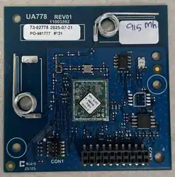

WS9501DLS
User manual
Supports the global license-free ISM 433MHz band.
Reception sensitivity no less than -120 dBm at an airspeed of 9.6kbps
Support2-(G)FSKModulation method
3-5.3Wide voltage input
2x10-2.54 pin header interface, dimensions 45mm x 28mm x 10.5mm
UART Module

WS9501DLS User manual
2 / 20
Document Information
Product Model
WS9501DLS
Product Overview
EFR32FG23 Uart Module
Document type
User manual
Document Number
Document Version
v2.1
2023.06.14
Document version updated
Serial
number
Version
number
Revised content
Revision date
Reviser
1
v1.0
Initial version
2022.08.09
2
v2.0
Update format
2022.09.20
3
v2.1
Update Frequency range
2023.06.14

WS9501DLS User manual
3 / 20
1 ProductOverview ........................................................................................................................................................................................ 4
1.1 ProductIntroduction ...................................................................................................................................................................... 4
1.2 Features and functions ................................................................................................................................................................. 4
1.3 Application scenario ..................................................................................................................................................................... 4
2 Pin definitions ............................................................................................................................................................................................. 5
3 Electricaland othersParameter .............................................................................................................................................................. 7
3.1 Limit parameters............................................................................................................................................................................. 7
3.2 Work parameters ............................................................................................................................................................................ 7
3.3 Radio frequencyPerformance parameters............................................................................................................................. 7
3.4 Other parameters ........................................................................................................................................................................... 8
4 ModulePackage size ................................................................................................................................................................................. 9

WS9501DLS User manual
4 / 20
1 ProductOverview
1.1 ProductIntroduction
The WS9501, based on the EFR32FG23 SoC chip solution, is an ideal solution for sub-GHz “Internet of Things”
applications in smart home, security, lighting, building automation, and metering systems. Its high-performance
sub-GHz radio provides long-range communication while remaining resilient to interference from 2.4 GHz
technologies such as Wi-Fi. This single-chip multi-core solution delivers outstanding security, ultra-low power
consumption, and rapid wake-up times. It integrates internally a power amplifier, low-noise amplifier, SAW filter,
low-pass filter, and other components, enabling longer communication ranges, superior harmonic suppression,
and excellent anti-interference performance.
1.2 Features and functions
Features and functions
Support 433.1025-434.6025MHz
3—5.3Wide voltage input
Support2-(G)FSKModulation method
On-chip 20dBm PA, On-board LNA, SAW, Low-pass filter
3.3Maximum Emission Current under V Supply80mA
Sleep current below 5uA
Reception sensitivity no less than -120 dBm @ airspeed 9..6kbps
Airspeed0.625kbps-4 MbpsAdjustable
Software Function LBTPower-on self-test, with out-of-band suppression hardware measures.
Industrial-grade standard design, supports-40℃~85℃Long-term use
2x10-2.54Pin header interface, 45mm 28mm x 10.5mm size
1.3 Application scenario
Application scenarios
Construction machinery control Wait
Remote control
Smart home devices and industrial sensors, among others
Smart agricultural sensors
Wireless alarm security system
Building Automation Solutions
Healthcare products
Advanced Metering Infrastructure (AMI)
WS9501DLS User manual
5 / 20
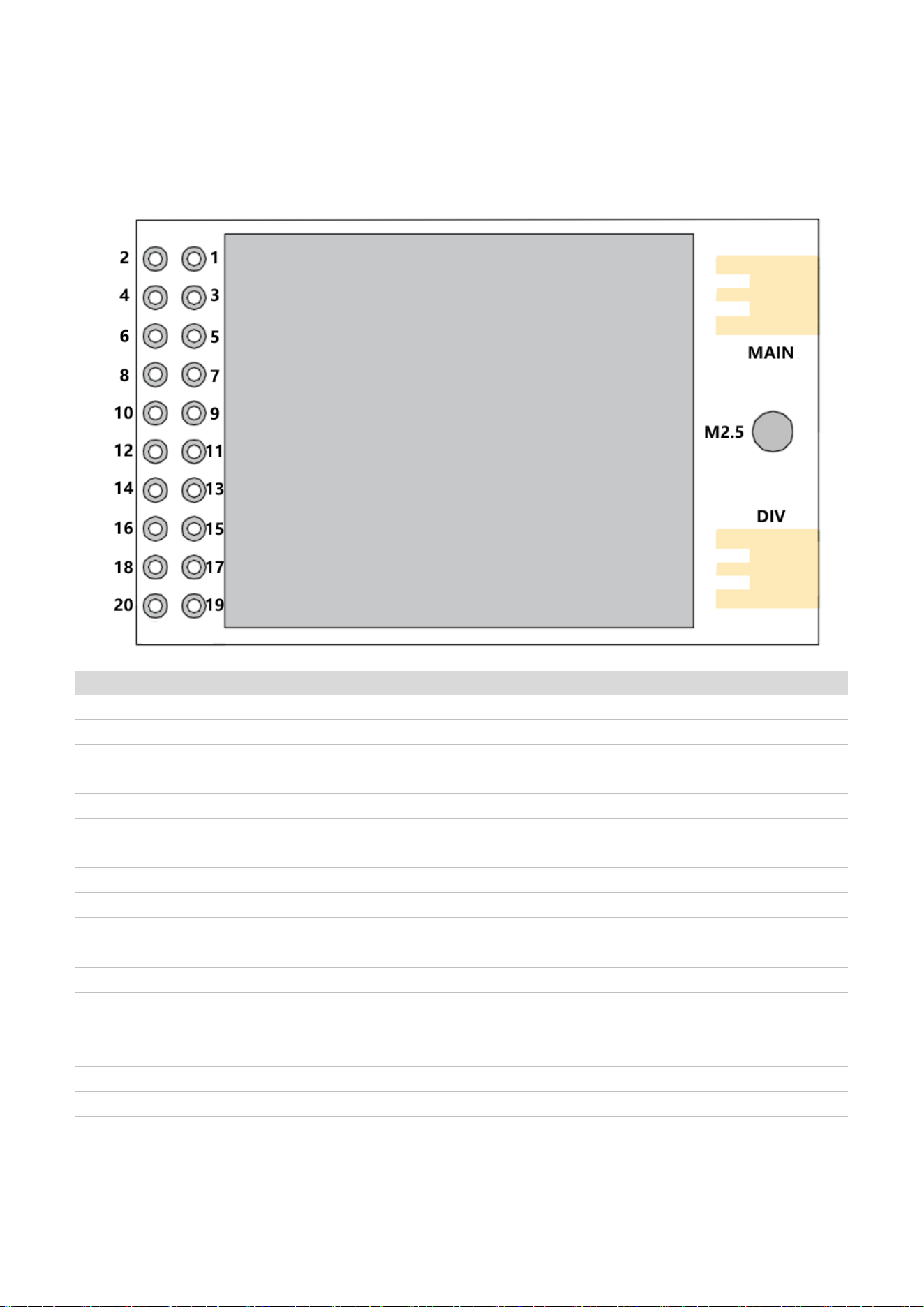
2 Pin definitions
Pin name
Type
Description
1
GND
I
Power reference ground
2
GND
I
Power reference ground
3
TXD
O
The module sends data,Internal
chipPA08,ExternalRecommendationAdd pull
4
SLEEP
I
Module sleep: High level—wake up; Low level—sleep.
5
RXD
I/O
The module receives data; internal chip PA0.6,External
recommendationsAdd pull
6
WAKEUP
O
Module wake-up output, high-level wake-up
7
PA04
I/O
Reserved I/O
8
PA03
I/O
Reserved I/O
9
SWDIO
I/O
Module program burning interface
10
SWCLK
I
Module program burning interface
11
STATUS
O
Module status indicator output,Low level: Module idle High
level: Module busy
12
Heartbeat
O
Module heartbeat output, output is100HertzSquare wave
13
M0
I
Mode 0 pin, internal chip PC01
14
PC02
I/O
General IO
15
M1
I
Mode 1 pin, internal chip PC03
16
nRESET
I
Module reset, active low

WS9501DLS User manual
6 / 20
17
GND
I
Power reference ground
18
GND
I
Power reference ground
19
VDD1
I
Module power supplyInput
20
VDD2
I
Module power supplyInput
MAIN
ANT2
I/O
Main antenna,MMCXMother seat,Send and receiveOne
piece
DIV
ANT1
I/O
Auxiliary antenna,MMCXMother seat,Does not come
soldered by default.
M2.5
2.7mm hole
For non-metallic fixed screw holes, it is recommended to use
M.2.5Screw
For detailed information on the pin definitions, software drivers, and communication protocols of the module,
please refer to:Silicon LabsOfficialEFRA32FG32Datasheet

WS9501DLS User manual
7 / 20
3 Electricaland othersParameter
3.1 Limit parameters
Parameter
Symbol
MinimumValue
Maximum value
Unit
Power supply
voltage
VCC
-0.3
6
V
Interface voltage
V
IN
-0.3
3.7
V
Storage
temperature
T
STG
-40
85
Celsius
3.2 Work parameters
Parameter
Symbol
MinimumValue
Typical value
Maximum value
Unit
WorkVoltage
VCC
3
3.3
5.3
V
Communication
level
V
IN
3
3.3
3.6
V
Operating
temperature
T
OP
-40
85
Celsius
3.3 Radio frequencyPerformance parameters
Parameter
Minimum
value
Typical value
Maximum
value
Unit
Note
Operating
frequency band
433.1025
434
434.65
MHz
Modulation
method
2-GFSK
-
Reception
bandwidth
-
25
500
kHertz
Maximum
transmit power
18.5
19
20
dBm
Reception
sensitivity
-
-120
-
dBm
@5V 433.1025MHz,
2-GFSK,9.6 kilobits per
second, ±3.3kHz deviation
LaunchCurrent
75
80
85
mA
@5V 20dBm
LaunchCurrent
18.5
21.5
24.5
mA
@5V 10dBm
ReceiveCurrent
16
17.5
20
mA
@5V 20dBm
Receive current
10
12
4
mA
@5V 10dBm

WS9501DLS User manual
8 / 20
IdleCurrent
-
5
-
uA
@5V
3.4 Other parameters
Parameter
Description
Communication
interface
UART
RF interface
MMCXMother seat
Packaging
method
Direct insertionFormula
Interface
method
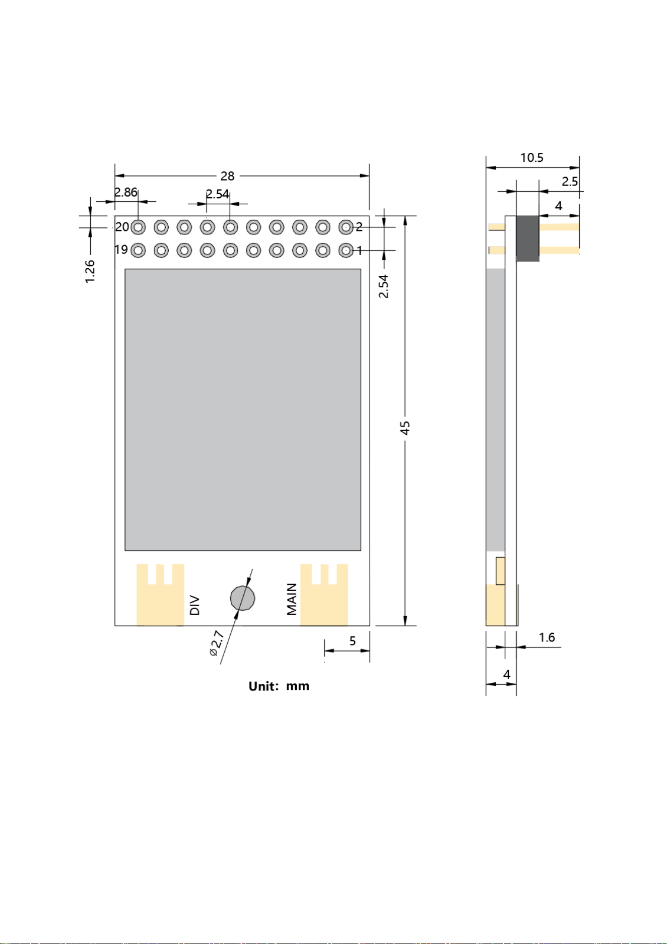
2x10-2.54mm pin header
External
dimensions
45*28*10.5mm
WS9501DLS User manual
9 / 20
4 ModulePackage size

WS9501DLS User manual
10 / 20
FCC Statement
This device complies with part 15 of the FCC Rules. Operation is subject to the following two
conditions:
(1) This device may not cause harmful interference, and
(2) this device must accept any interference received, including interference that may cause undesired operation.
Any Changes or modifications not expressly approved by the party responsible for compliance could void the user's
authority to operate the equipment.
This equipment complies with FCC radiation exposure limits set forth for an uncontrolled environment. This equipment
should be installed and operated with minimum distance 20cm between the radiator & your body.
Any company of the host which install this modular with Single modular approval should perform the test of radiated
emission and spurious emission according to FCC Part 15C. requirement, Only if the test result comply with FCC Part 15C
requirement, then the host can be sold legally.
FCC Radiation Exposure Statement
This modular complies with FCC RF radiation exposure limits set forth for an uncontrolled environment. This transmitter
must not be co-located or operating in conjunction with any other antenna or transmitter. This modular must be installed
and operated with a minimum distance of 20 cm between the radiator and user body.
Note: This equipment has been tested and found to comply with the limits for a Class B digital device, pursuant to part 15
of the FCC Rules. These limits are designed to provide reasonable protection against harmful interference in a residential
installation. This equipment generates uses and can radiate radio frequency energy and, if not installed and used in
accordance with the instructions, may cause harmful interference to radio communications. However, there is no
guarantee that interference will not occur in a particular installation. If this equipment does cause harmful interference to
radio or television reception, which can be determined by turning the equipment off and on, the user is encouraged to try
to correct the interference by one or more of the following measures:
-Reorient or relocate the receiving antenna.
-Increase the separation between the equipment and receiver.
-Connect the equipment into an outlet on a circuit different from that to which the receiver is connected.
-Consult the dealer or an experienced radio/TV technician for help.

WS9501DLS User manual
11 / 20
OEM INTEGRATION INSTRUCTIONS:
This device is intended only for OEM integrators under the following conditions:
The module must be installed in the host equipment such that 20 cm is maintained between the antenna and users, and the
transmitter module may not be co-located with any other transmitter or antenna. The module shall be only used with the
internal on-board antenna that has been originally tested and certified with this module. External antennas are not
supported. As long as these 3 conditions above are met, further transmitter test will not be required.
However, the OEM integrator is still responsible for testing their end-product for any additional compliance requirements
required with this module installed (for example, digital device emissions, PC peripheral requirements, etc.). The
end-product may need Verification testing, Declaration of Conformity testing, a Permissive Class II Change or new
Certification. Please involve a FCC certification specialist in order to determine what will be exactly applicable for the
end-product.
Validity of using the module certification:
In the event that these conditions cannot be met (for example certain laptop configurations or co-location with another
transmitter), then the FCC/IC authorization for this module in combination with the host equipment is no longer considered
valid and the FCC ID/IC of the module cannot be used on the final product. In these circumstances, the OEM integrator will
be responsible for re-evaluating the end product (including the transmitter) and obtaining a separate FCC authorization. In
such cases, please involve a FCC/IC certification specialist in order to determine if a Permissive Class II Change or new
Certification is required.
Upgrade Firmware:
The software provided for firmware upgrade will not be capable to affect any RF parameters as certified for the FCC for this
module, in order to prevent compliance issues.
End product labeling:
This transmitter module is authorized only for use in device where the antenna may be installed such that 20 cm may be
maintained between the antenna and users. The final end product must be labeled in a visible area with the following:
“Contains Transmitter Module FCC ID: 2BXHF-WS9501DLS Or Contains FCC ID: 2BXHF-WS9501DLS”
Information that must be placed in the end user manual:
The OEM integrator has to be aware not to provide information to the end user regarding how to install or remove this RF
module in the user's manual of the end product which integrates this module. The end user manual shall include all
required regulatory information/warning as show in this manual.

WS9501DLS User manual
12 / 20
2.2 List of applicable FCC rules
List the FCC rules that are applicable to the modular transmitter. These are the rules that specifically establish the bands of
operation, the power, spurious emissions, and operating fundamental frequencies. DO NOT list compliance to
unintentional-radiator rules (Part 15 Subpart B) since that is not a condition of a module grant that is extended to a host
manufacturer. See also Section 2.10 below concerning the need to notify host manufacturers that further testing is
required.
Explanation: This module meets the requirements of FCC Part 15C.
2.3 Summarize the specific operational use conditions
Describe use conditions that are applicable to the modular transmitter, including for example any limits on antennas, etc.
For example, if point-to-point antennas are used that require reduction in power or compensation for cable loss, then this
information must be in the instructions. If the use condition limitations extend to professional users, then instructions must
state that this information also extends to the host manufacturer’s instruction manual. In addition, certain information may
also be needed, such as peak gain per frequency band and minimum gain, specifically for master devices in 5 GHz DFS
bands.
Explanation: This module is only applicable to the 433.1025 MHz - 434.6025 MHz frequency band. It should be installed
inside the main unit and kept at a distance of more than 20 cm from the human body. The use of the antenna requires
compliance with Clause 2.7.
2.4 Limited module procedures
If a modular transmitter is approved as a “limited module,” then the module manufacturer is responsible for approving the
host environment that the limited module is used with. The manufacturer of a limited module must describe, both in the
filing and in the installation instructions, the alternative means that the limited module manufacturer uses to verify that the
host meets the necessary requirements to satisfy the module limiting conditions.
A limited module manufacturer has the flexibility to define its alternative method to address the conditions that limit the
initial approval, such as: shielding, minimum signaling amplitude, buffered modulation/data inputs, or power supply
regulation. The alternative method could include that the limited module manufacturer reviews detailed test data or host
designs prior to giving the host manufacturer approval.
This limited module procedure is also applicable for RF exposure evaluation when it is necessary to demonstrate
compliance in a specific host. The module manufacturer must state how control of the product into which the modular
transmitter will be installed will be maintained such that full compliance of the product is always ensured. For additional
hosts other than the specific host originally granted with a limited module, a Class II permissive change is required on
the module grant to register the additional host as a specific host also approved with the module.
Explanation: The Module is not a limited module.
2.5 Trace antenna designs
For a modular transmitter with trace antenna designs, see the guidance in Question 11 of KDB
Publication 996369 D02 FAQ – Modules for Micro-Strip Antennas and traces. The integration information shall include for
the TCB review the integration instructions for the following aspects: layout of trace design, parts list (BOM), antenna,
connectors, and isolation requirements.
a) Information that includes permitted variances (e.g., trace boundary limits, thickness, length,

WS9501DLS User manual
13 / 20
width, shape(s),
dielectric constant, and impedance as applicable for each type of antenna);
b) Each design shall be considered a different type (e.g., antenna length in multiple(s) of frequency,
the wavelength, and antenna shape (traces in phase) can affect antenna gain and must be considered); c) The parameters
shall be provided in a manner permitting host manufacturers to design the printed circuit (PC) board layout;
d) Appropriate parts by manufacturer and specifications;
e) Test procedures for design verification; and
f) Production test procedures for ensuring compliance.
The module grantee shall provide a notice that any deviation(s) from the defined parameters of the antenna trace, as
described by the instructions, require that the host product manufacturer must notify the module grantee that they wish to
change the antenna trace design. In this case, a Class II permissive change application is required to be filed by the
grantee, or the host manufacturer can take responsibility through the change in FCC ID (new application) procedure
followed by a Class II permissive change application.
Explanation: Yes, The module with Snap fastener port designs, and this EUT has been shown the layout of trace design,
antenna, connectors requirements.
2.6 RF exposure considerations
It is essential for module grantees to clearly and explicitly state the RF exposure conditions that permit a host product
manufacturer to use the module. Two types of instructions are required for RF exposure information: (1) to the host product
manufacturer, to define the application conditions (mobile, portable – 20cm from a person’s body); and (2) additional text
needed for the host product manufacturer to provide to end users in their end-product manuals. If RF exposure statements
and use conditions are not provided, then the host product manufacturer is required to take responsibility of the module
through a change in FCC ID/IC (new application).
Explanation: This module complies with FCC RF radiation exposure limits set forth for an uncontrolled environment, This
equipment should be installed and operated with a minimum distance of 20 centimeters between the radiator and your
body." This module is designed to comply with the FCC statement, “Contains Transmitter Module FCC ID:
2BXHF-WS9501DLS Or Contains FCC ID: 2BXHF-WS9501DLS”
2.7 Antennas
A list of antennas included in the application for certification must be provided in the instructions. For modular transmitters
approved as limited modules, all applicable professional installer instructions must be included as part of the information to
the host product manufacturer. The antenna list shall also identify the antenna types (monopole, PIFA, dipole, etc. (note
that for example an “omni-directional antenna” is not considered to be a specific “antenna type”)).
For situations where the host product manufacturer is responsible for an external connector, for example with an RF pin
and antenna trace design, the integration instructions shall inform the installer that unique antenna connector must be
used on the Part 15 authorized transmitters used in the host product.
The module manufacturers shall provide a list of acceptable unique connectors.
WS9501DLS User manual
14 / 20
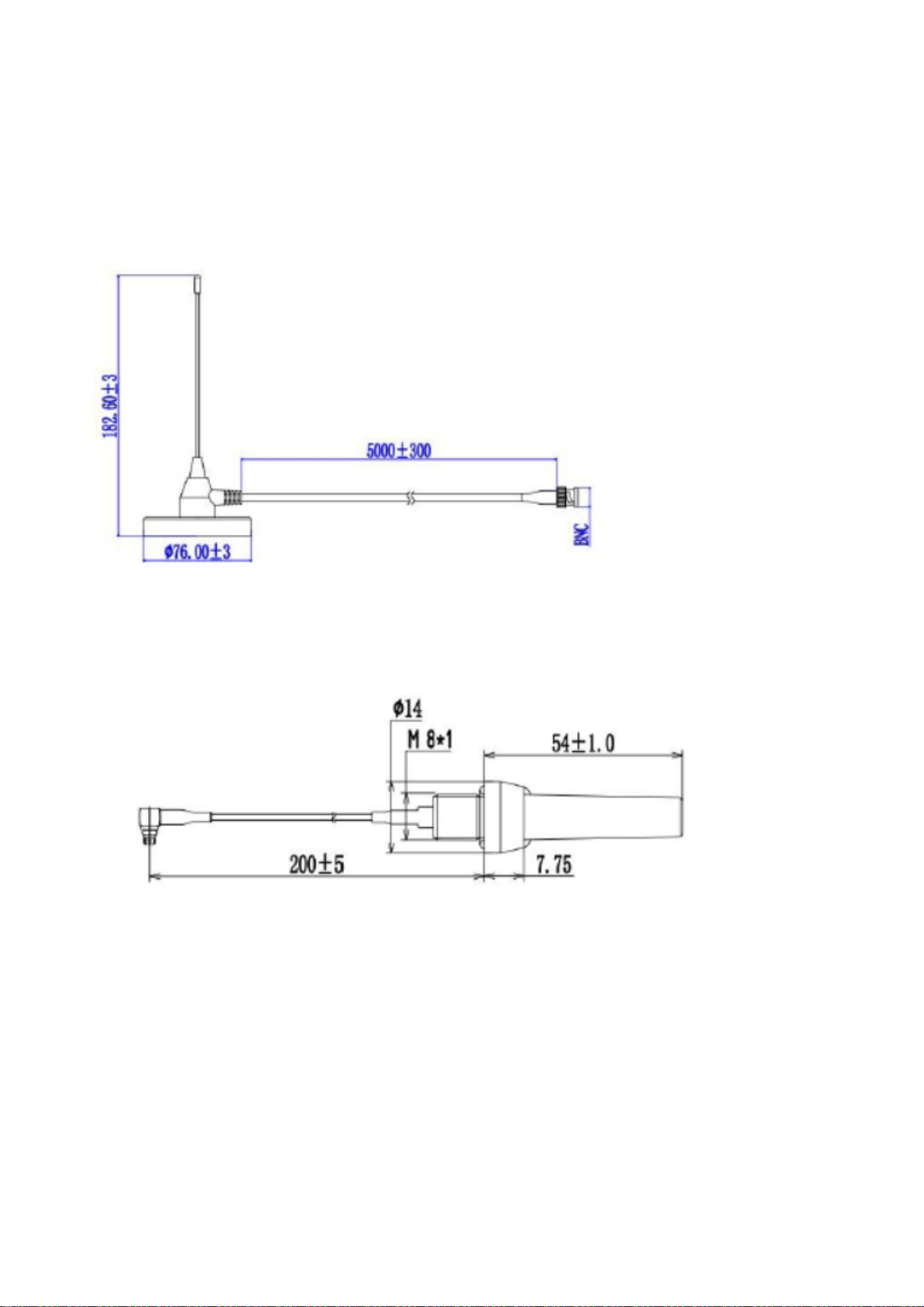
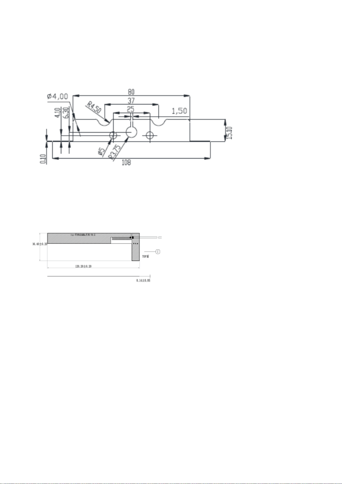
Explanation: This module employs four antennas, three external antennas and one internal antenna, and the antenna use
which is unique.
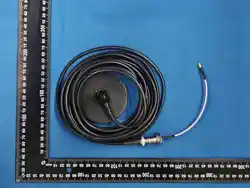
Model A: STXPA187650BAB433
Type: Sucker antenna
Manufacturer: SHANGHAI ZHENYI COMMUNICATION TECHNOLOGY CO., LTD.
Antenna gain: 1dBi
Model B: STDPA551420MBA433
Type: Dipole Antenna
Manufacturer: SHANGHAI ZHENYI COMMUNICATION TECHNOLOGY CO., LTD.
Antenna gain:-2dBi
WS9501DLS User manual
15 / 20
Model C: STDPA1357715MBA433
Type: Horn Antenna
Manufacturer: SHANGHAI ZHENYI COMMUNICATION TECHNOLOGY CO., LTD.
Antenna gain: 0.5dBi
Model D: STDPA1357715MBA433
Type: FPC Antenna
Manufacturer: SHANGHAI ZHENYI COMMUNICATION TECHNOLOGY CO., LTD.
Antenna gain: -3.5 dBi
2.8 Label and compliance information
Grantees are responsible for the continued compliance of their modules to the FCC/IC rules. This includes advising host
product manufacturers that they need to provide a physical or e-label stating “Contains FCC ID” with their finished product.
See Guidelines for Labeling and User Information for RF Devices – KDB Publication 784748.
Explanation: The host system using this module, should have label in a visible area indicated the following texts: “Contains
Transmitter Module FCC ID: 2BXHF-WS9501DLS Or Contains FCC ID: 2BXHF-WS9501DLS”
2.9 Information on test modes and additional testing requirements5
Additional guidance for testing host products is given in KDB Publication 996369 D04 Module Integration Guide. Test
modes should take into consideration different operational conditions for a stand-alone modular transmitter in a host, as
well as for multiple simultaneously transmitting modules or other transmitters in a host product.
The grantee should provide information on how to configure test modes for host product evaluation for different operational
conditions for a stand-alone modular transmitter in a host, versus with multiple, simultaneously transmitting modules or
other transmitters in a host.
Grantees can increase the utility of their modular transmitters by providing special means, modes, or instructions that

WS9501DLS User manual
16 / 20
simulates or characterizes a connection by enabling a transmitter. This can greatly simplify a host manufacturer’s
determination that a module as installed in a host complies with FCC requirements.
Explanation: Top band can increase the utility of our modular transmitters by providing instructions that simulates or
characterizes a connection by enabling a transmitter.
2.10 Additional testing, Part 15 Subpart B disclaimer
The grantee should include a statement that the modular transmitter is only FCC authorized for the specific rule parts (i.e.,
FCC transmitter rules) listed on the grant, and that the host product manufacturer is responsible for compliance to any
other FCC rules that apply to the host not covered by the modular transmitter grant of certification. If the grantee markets
their product as being Part 15 Subpart B compliant (when it also contains unintentional-radiator digital circuity), then the
grantee shall provide a notice stating that the final host product still requires Part 15 Subpart B compliance testing with the
modular transmitter installed.
Explanation: The module without unintentional-radiator digital circuity, so the module does not require an evaluation by
FCC Part 15 Subpart B. The host shoule be evaluated by the FCC Subpart B.

WS9501DLS User manual
17 / 20
IC Statement
This device contains licence-exempt transmitter(s)/receiver(s) that comply with Innovation, Science and Economic
Development Canada’s licence-exempt RSS(s). Operation is subject to the following two conditions:
1. This device may not cause interference.
2. This device must accept any interference, including interference that can cause undesired operation of the device.
L’émetteur ou le récepteur exempt de licence contenu dans le présent appareil est conforme aux CNR d’Innovation,
Sciences et Développement économique Canada applicables aux appareils radio exempts de licence. L’exploitation est
autorisée aux deux conditions suivantes :
1.L’appareil ne doit pas produire de brouillage.
2.L’appareil doit accepter tout brouillage radioélectrique subi, même si le brouillage est susceptible d’en compromettre le
fonctionnement.
This radio transmitter [IC: 36001-WS9501DLS] has been approved by Innovation, Science and Economic Development
Canada to operate with the antenna types listed below, with the maximum permissible gain indicated. Antenna types not
included in this list that have a gain greater than the maximum gain indicated for any type listed are strictly prohibited for
use with this device.
Le présent émetteur radio IC: 36001-WS9501DLS] a été approuvé par Innovation, Sciences et Développement
économique Canada pour fonctionner avec les types d'antenne énumérés ci-dessous et en ayant un gain admissible
maximal tel qu'indiqué. Les types d'antenne non inclus dans cette liste, et dont le gain est supérieur au gain maximal
indiqué pour tout type figurant sur la liste, sont strictement interdits pour l'exploitation de l'émetteur.
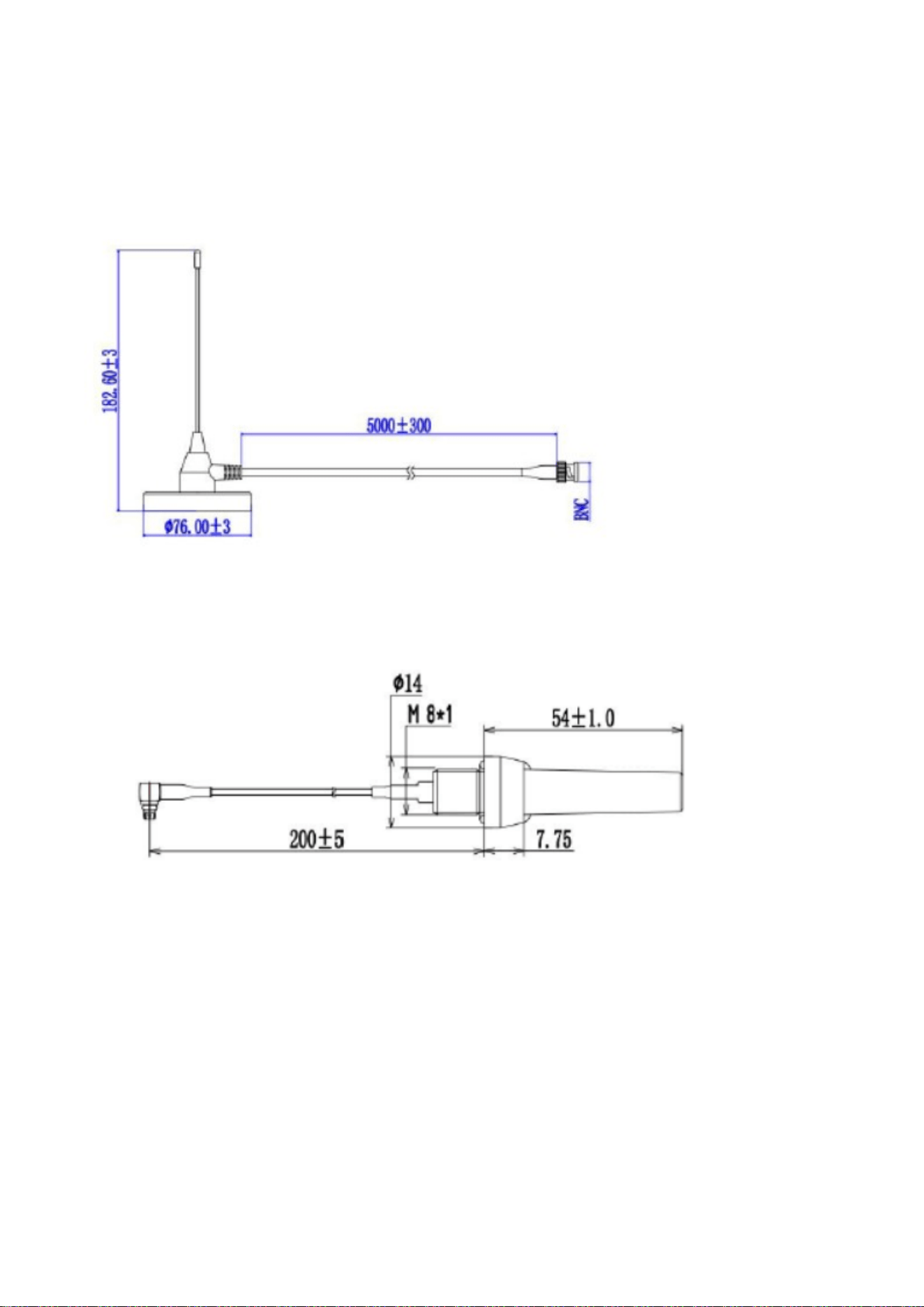
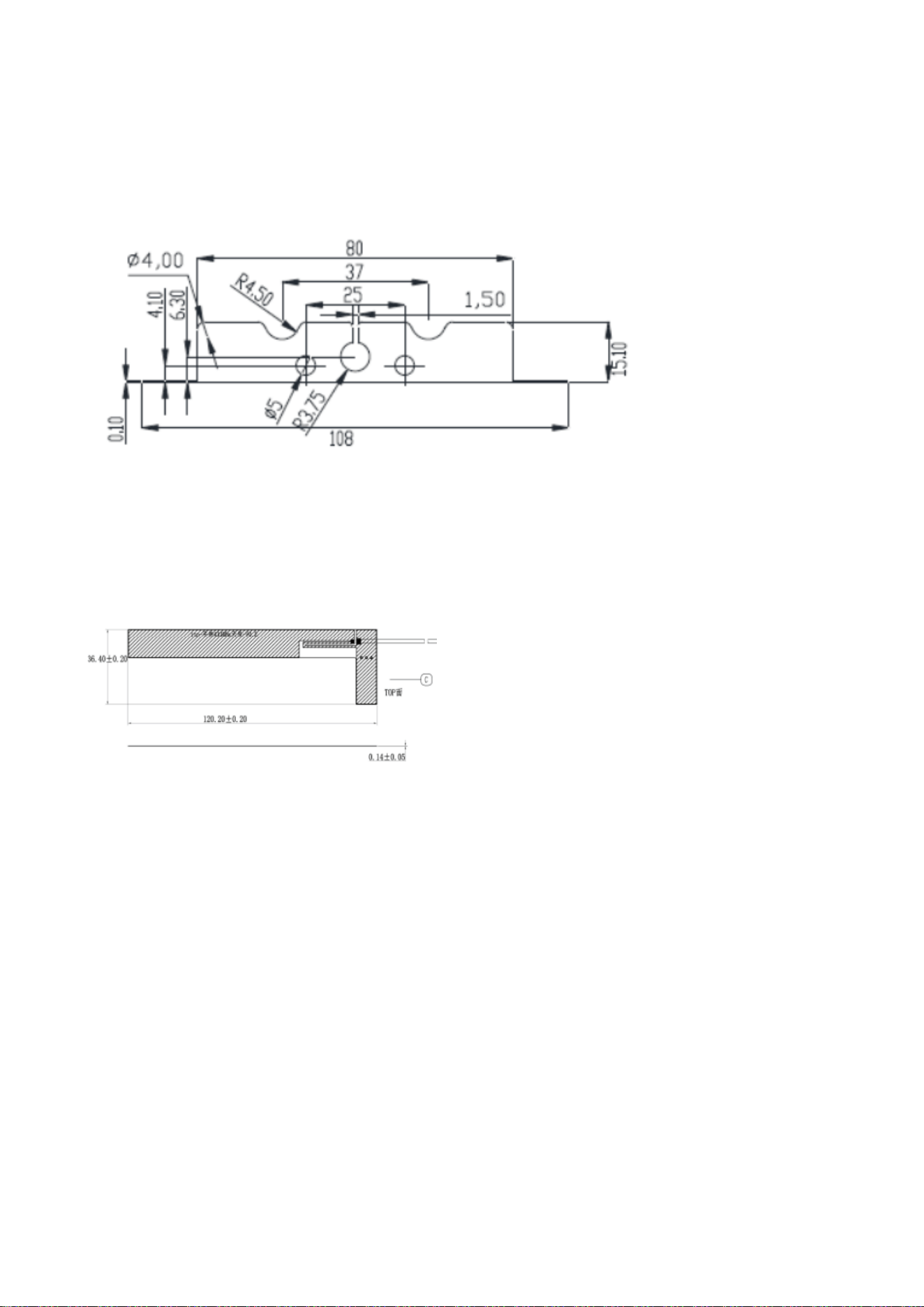
This module employs four antennas, three external antennas and one internal antenna, and the antenna use which is
unique.
Ce module utilise quatre antennes, trois antennes externes et une antenne interne, avec un usage d'antennes unique.
WS9501DLS User manual
18 / 20
Model A: STXPA187650BAB433
Type: Sucker antenna
Manufacturer: SHANGHAI ZHENYI COMMUNICATION TECHNOLOGY CO., LTD.
Antenna gain: 1dBi
Model B: STDPA551420MBA433
Type: Dipole Antenna
Manufacturer: SHANGHAI ZHENYI COMMUNICATION TECHNOLOGY CO., LTD.
Antenna gain:-2dBi
WS9501DLS User manual
19 / 20
Model C: STDPA1357715MBA433
Type: Horn Antenna
Manufacturer: SHANGHAI ZHENYI COMMUNICATION TECHNOLOGY CO., LTD.
Antenna gain: 0.5dBi
Model D: STDPA1357715MBA433
Type: FPC Antenna
Manufacturer: SHANGHAI ZHENYI COMMUNICATION TECHNOLOGY CO., LTD.
Antenna gain: -3.5 dBi
Radiation Exposure Statement
This modular complies with IC RF radiation exposure limits set forth for an uncontrolled environment. This transmitter must
not be co-located or operating in conjunction with any other antenna or transmitter. This modular must be installed and
operated with a minimum distance of 20 cm between the radiator and user body.
Ce module respecte les limites d'exposition aux rayonnements radiofréquences IC établies pour un environnement non
contrôlé. Ce transmetteur ne doit pas être placé à proximité ou fonctionner conjointement avec une autre antenne ou un
autre émetteur. Ce module doit être installé et utilisé en respectant une distance minimale de 20 cm entre le radiateur et le
corps de l'utilisateur.
If the ISED identification number is not visible when the module is installed inside another device, then the outside of the
device into which the module is installed must also display a label referring to the enclosed module. This exterior label can
use wording such as the following:
“Contains Transmitter Module IC: 36001-WS9501DLS Or Contains IC: 36001-WS9501DLS”
Si le numéro d'identification ISED n'est pas visible lorsque le module est installé dans un autre appareil, alors l'extérieur de
l'appareil dans lequel le module est installé doit également afficher une étiquette indiquant le module intégré. Cette
étiquette extérieure peut utiliser des formulations telles que les suivantes :

WS9501DLS User manual
20 / 20
« Contient module émetteur IC : 36001-WS9501DLS ou contient IC : 36001-WS9501DLS »
When the module is installed inside another device, the user manual of the host must contain
below warning statements;
1. This device contains licence-exempt transmitter(s)/receiver(s) that comply with Innovation, Science and Economic
Development Canada's licence-exempt RsS(s). Operation is subject to the following two conditions:
(1) This device may not cause interference; and
(2) This device must accept any interference, including interference that may cause undesired operation of the device.
Lorsque le module est installé à l'intérieur d'un autre appareil, le manuel d'utilisateur de l'hôte doit contenir les
avertissements suivants ;
1. Cet appareil contient un émetteur/récepteur exempt de licence conforme aux réglementations RsS(s) exemptes de
licence de l'Innovation, Science and Economic Development Canada. Son fonctionnement est soumis aux deux conditions
suivantes :
(1) Cet appareil ne doit pas provoquer d'interférences ; et
(2) Cet appareil doit accepter toute interférence, y compris celles pouvant entraîner un fonctionnement indésirable de
l'appareil.
2. Changes or modifications not expressly approved by the party responsible for compliance could void the user's authority
to operate the equipment. The devices must be installed and used in strict accordance with the manufacturer's instructions
as described in the user documentation that comes with the product.
Toute modification ou changement non expressément approuvé par la partie responsable de la conformité pourrait annuler
le droit de l'utilisateur d'exploiter l'équipement. Les appareils doivent être installés et utilisés strictement conformément aux
instructions du fabricant, telles que décrites dans la documentation utilisateur fournie avec le produit.
Any company of the host device which install this modular with Single modular approval should perform the test of radiated
emission and spurious emission according to RSS-210 requirement, Only if the test result comply with RSS-210
requirement,then the host can be sold legally.
Toute entreprise du dispositif hôte qui installe ce module avec une approbation modulaire unique doit effectuer les tests
d'émission rayonnée et d'émission parasite conformément aux exigences de la norme RSS-210. Seul si les résultats des
tests sont conformes aux exigences de la norme RSS-210, le dispositif hôte peut être vendu légalement.