Instructions for Use
TN-UHF-Q150-…-EN
UHF Reader

Contents
TURCK GmbH | T +49 208 4952-0 | [email protected] | www.turck.com
V02.00 | 2025/09 | 2
Contents
1 About these Instructions ...................................................................................................................5
1.1 Target groups ...................................................................................................................5
1.2 Explanation of symbols ..................................................................................................5
1.3 Other documents.............................................................................................................5
1.4 Naming convention.........................................................................................................5
1.5 Feedback about these instructions ..............................................................................5
2 Notes on the product .........................................................................................................................6
2.1 Product identification .....................................................................................................6
2.2 Scope of delivery..............................................................................................................6
2.3 TURCK service...................................................................................................................6
3 For your safety.....................................................................................................................................7
3.1 Intended use .....................................................................................................................7
3.2 General safety notes........................................................................................................7
3.3 Notes on EU Directive 2014/53/EU (RED Directive)...................................................8
4 Product description ............................................................................................................................9
4.1 Device overview...............................................................................................................9
4.1.1 Indication elements.........................................................................................................................9
4.2 Properties and features ..................................................................................................9
4.3 Operating principle ...................................................................................................... 10
4.4 Functions and operating modes................................................................................ 10
4.4.1 Operating frequency.................................................................................................................... 11
4.4.2 Combination of UHF readers and tags .................................................................................. 11
4.4.3 Multiprotocol function................................................................................................................ 11
4.4.4 Data transfer to the PLC.............................................................................................................. 12
4.4.5 RFID channels — operating modes........................................................................................ 12
4.4.6 RFID commands............................................................................................................................. 12
4.4.7 Loop counter function................................................................................................................. 13
4.5 Technical accessories ................................................................................................... 13
5 Installing ............................................................................................................................................ 14
6 Connecting ........................................................................................................................................ 15
6.1 Connecting devices to Ethernet................................................................................. 15
6.2 Connecting the power supply.................................................................................... 16
6.3 Connecting the external antenna.............................................................................. 16
7 Commissioning................................................................................................................................. 17
7.1 Parameterizing the reader using the web server ................................................... 17
7.1.1 Opening a web server.................................................................................................................. 17
7.1.2 Editing settings in the web server........................................................................................... 17
7.1.3 Multiplex operation...................................................................................................................... 19
7.1.4 Setting antenna power ............................................................................................................... 22
7.1.5 Setting antenna polarization .................................................................................................... 25
7.1.6 Switching on presence sensing mode................................................................................... 28
7.1.7 Transferring the RSSI value — communication ................................................................. 29
7.1.8 Setting the RSSI filter — post read filter ............................................................................... 30
7.2 Testing the reader using the web server.................................................................. 31

Contents
TURCK GmbH | T +49 208 4952-0 | [email protected] | www.turck.com
V02.00 | 2025/09 | 3
7.3 Adjusting network settings ........................................................................................ 33
7.3.1 Adjusting network settings via TAS (TURCK Automation Suite).................................. 33
7.3.2 Adjusting network settings via the web server.................................................................. 35
7.4 Connecting the device to a Modbus master with CODESYS ................................ 36
7.4.1 Connecting the device with the controller.......................................................................... 37
7.4.2 Renaming a Modbus slave......................................................................................................... 41
7.4.3 Setting up network interfaces .................................................................................................. 42
7.4.4 Modbus TCP slave — setting the IP address ....................................................................... 43
7.4.5 Defining Modbus channels (registers)................................................................................... 43
7.4.6 Connecting the device online with the controller ............................................................ 45
7.4.7 Reading out process data........................................................................................................... 45
7.4.8 Modbus TCP — mapping........................................................................................................... 45
7.5 Connecting the device to an EtherNet/IP scanner using RSLogix....................... 46
7.5.1 Installing an EDS file..................................................................................................................... 46
7.5.2 Connecting the device with the controller.......................................................................... 50
7.5.3 Connecting the device online with the controller ............................................................ 54
7.5.4 Reading out process data........................................................................................................... 56
7.6 Connecting the device to a PROFINET master using the TIA Portal.................... 58
7.6.1 Installing a GSDML file................................................................................................................. 59
7.6.2 Connecting the device with the controller.......................................................................... 60
7.6.3 Assigning the PROFINET device name................................................................................... 61
7.6.4 Setting the IP address in the TIA Portal................................................................................. 62
7.6.5 Connecting the device online with the controller ............................................................ 63
7.6.6 Setting module parameters....................................................................................................... 63
7.6.7 PROFINET mapping ...................................................................................................................... 63
8 Setting................................................................................................................................................ 64
8.1 RFID channels — parameter data.............................................................................. 65
8.1.1 Meaning of the parameter bits................................................................................................. 66
8.1.2 UHF applications — setting Continuous Presence Sensing Mode ............................. 66
8.1.3 UHF applications — transferring reader settings.............................................................. 67
8.2 RFID channels — process input data ........................................................................ 68
8.2.1 Meaning of the status bits.......................................................................................................... 70
8.2.2 Tag in detection range (TP) — using bit or pre-loading the command.................... 71
8.3 RFID channels — process output data...................................................................... 72
8.3.1 Meaning of the command bits................................................................................................. 74
8.4 RFID channels — overview of the commands......................................................... 75
8.4.1 Command: Idle............................................................................................................................... 77
8.4.2 Command: Inventory................................................................................................................... 78
8.4.3 Command: Read ............................................................................................................................ 81
8.4.4 Command: Write............................................................................................................................ 83
8.4.5 Command: Write and verify....................................................................................................... 85
8.4.6 Command: Continuous mode .................................................................................................. 87
8.4.7 Command: Get data from buffer (Continuous mode) ..................................................... 89
8.4.8 Command: UHF continuous presence sensing mode ..................................................... 92
8.4.9 Command: End Continuous (presence sensing) mode................................................... 93
8.4.10 Command: Read/write head identification ......................................................................... 94
8.4.11 Direct read/write head command........................................................................................... 95
8.4.12 Command: Set tag password.................................................................................................... 97
8.4.13 Command: Set read/write head password .......................................................................... 99
8.4.14 Command: Reset read/write head password....................................................................100
8.4.15 Command: Set tag protection................................................................................................101
8.4.16 Command: Tag info....................................................................................................................104
8.4.17 Command: Permanently deactivate UHF tags (Kill)........................................................106

Contents
TURCK GmbH | T +49 208 4952-0 | [email protected] | www.turck.com
V02.00 | 2025/09 | 4
8.4.18 Command: Restore UHF read/write head settings .........................................................107
8.4.19 Command: Backup settings of the UHF read/write head.............................................108
8.4.20 Command: Query error/status of UHF read/write head................................................109
8.4.21 Command: Reset .........................................................................................................................112
8.5 Setting RFID interfaces via the web server ............................................................113
8.5.1 Opening the web server ...........................................................................................................113
8.5.2 Editing settings in the web server.........................................................................................114
9 Operation......................................................................................................................................... 117
9.1 Executing a command and calling data .................................................................117
9.1.1 Typical times for command processing via a controller ...............................................117
9.2 Use fragmentation......................................................................................................118
9.2.1 Example: Using fragmentation in the web server — read ...........................................118
9.2.2 Example: Using fragmentation in the web server — write..........................................120
9.3 Using commands with a loop counter function.................................................... 122
9.4 Using the UHF password function...........................................................................123
9.4.1 Setting the Kill password..........................................................................................................123
9.5 Use CODESYS function blocks.................................................................................. 124
9.6 Using Inventory command and Continuous (Presence Sensing) Mode........... 127
9.7 LEDs ............................................................................................................................... 128
9.8 Software diagnostic messages................................................................................. 130
9.8.1 Diagnostic messages — gateway functions......................................................................130
9.8.2 Diagnostic messages — RFID channels ..............................................................................130
9.9 Example: Activating diagnostics via the PLC software........................................ 131
9.10 Reading error codes ...................................................................................................133
9.11 Using extended diagnostics — RFID channels...................................................... 137
10 Troubleshooting............................................................................................................................. 139
10.1 Rectifying errors.......................................................................................................... 139
11 Maintenance ...................................................................................................................................141
11.1 Updating the firmware via the Web server............................................................ 141
12 Repair ............................................................................................................................................... 142
12.1 Returning devices .......................................................................................................142
13 Disposal............................................................................................................................................ 143
14 Technical data.................................................................................................................................144
15 TURCK branches — contact data ................................................................................................ 146
16 Appendix: flow charts showing the operation of the device ................................................ 148
16.1 Flow chart: command processing............................................................................ 148
16.1.1 Handling command execution with Busy and Error — sample code in CODESYS
............................................................................................................................................................149
16.2 Flow chart: rapid command processing with loop counter................................ 150
16.3 Flow chart: command processing with fragmentation .......................................151
16.4 Flow chart: Continuous Mode with interruption before reading data............. 152
16.5 Flow chart: Continuous Mode without interruption before reading data ...... 153
16.6 Flow chart: programming tags with a password .................................................. 154
About these instructions
Feedback about these instructions
TURCK GmbH | T +49 208 4952-0 | [email protected] | www.turck.com
V02.00 | 2025/09 | 5
1 About these Instructions
These instructions describe the setup, functions and use of the product and help you to oper-
ate the product according to its intended purpose. Read these instructions carefully before us-
ing the product. This will prevent the risk of personal injury and damage to property. Keep
these instructions safe during the service life of the product. If the product is passed on, pass on
these instructions as well.
1.1 Target groups
These instructions are aimed at qualified personal and must be carefully read by anyone
mounting, commissioning, operating, maintaining, dismantling or disposing of the device.
1.2 Explanation of symbols
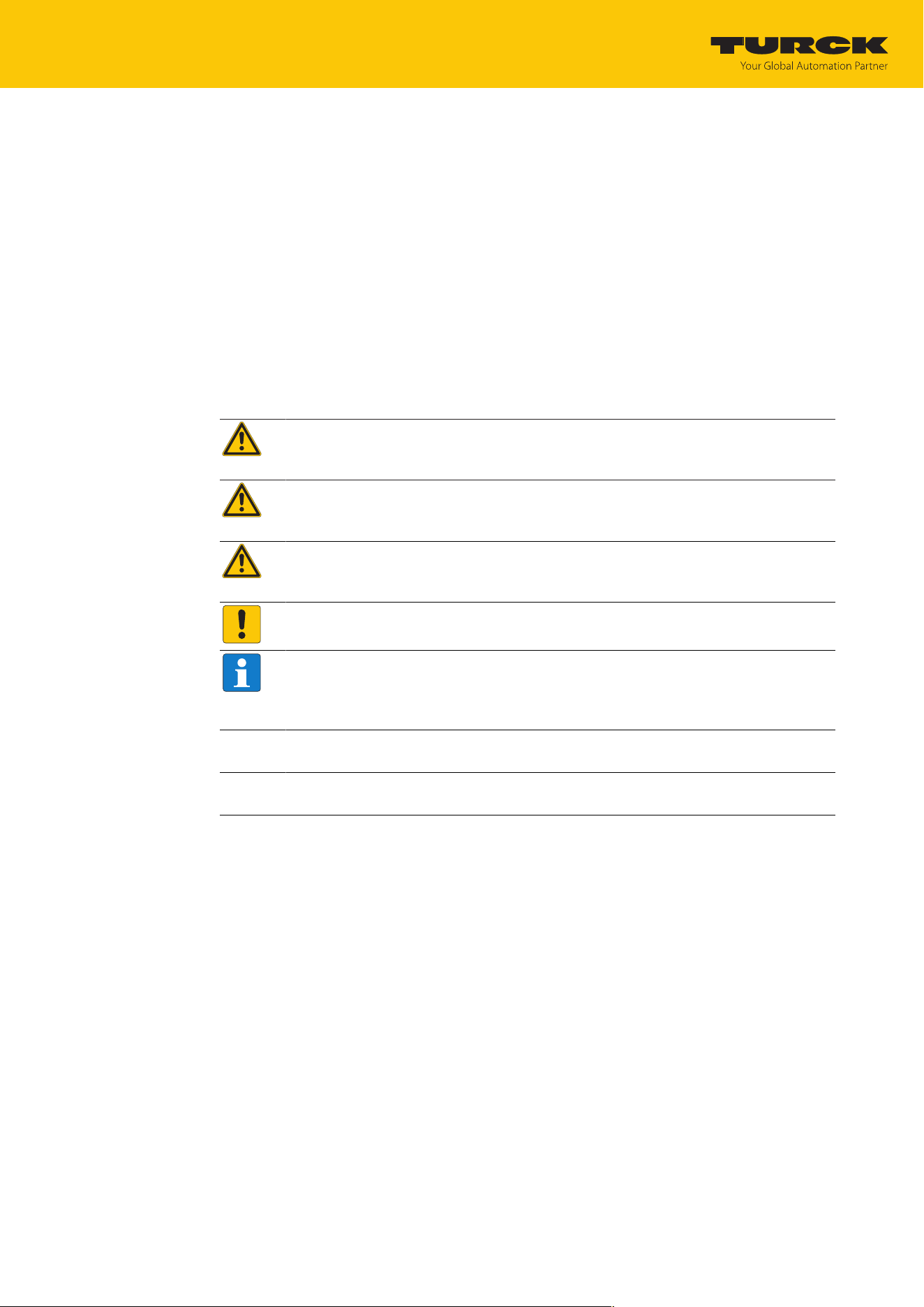
The following symbols are used in these instructions:
DANGER
DANGER indicates a hazardous situation with a high level of risk, which, if not
avoided, will result in death or serious injury.
WARNING
WARNING indicates a hazardous situation with a medium level of risk, which, if not
avoided, will result in death or serious injury.
CAUTION
CAUTION indicates a hazardous situation with a medium level of risk, which, if not
avoided, will result in moderate or minor injury.
NOTICE
CAUTION indicates a situation which, if not avoided, may cause damage to property.
NOTE
NOTE indicates tips, recommendations and important information about special ac-
tion steps and issues. The notes simplify your work and help you to avoid additional
work.
u
MANDATORY ACTION
This symbol denotes actions that the user must carry out.
a
RESULT OF ACTION
This symbol denotes the relevant results of an action.
1.3 Other documents
Besides this document the following material can be found on the Internet at www.turck.com:
n Data sheet
n Approvals
n Configuration manual
1.4 Naming convention
Read/write devices in the HF are called “read/write heads” and “readers” in the UHF area. “Tag”,
“transponder” and “mobile data memory” are common synonyms for “data carriers”.
1.5 Feedback about these instructions
We make every effort to ensure that these instructions are as informative and as clear as pos-
sible. If you have any suggestions for improving the design or if some information is missing in
the document, please send your suggestions to [email protected].
Notes on the product
TURCK service
TURCK GmbH | T +49 208 4952-0 | [email protected] | www.turck.com
V02.00 | 2025/09 | 6
2 Notes on the product
2.1 Product identification
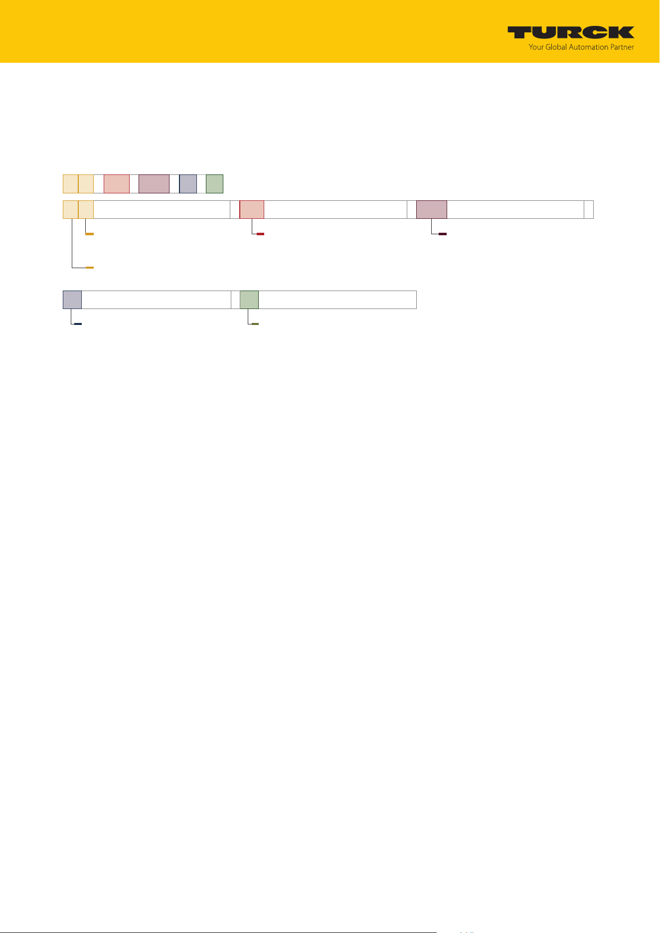
These instructions apply to the following UHF readers:
T N
-
UHF
-
Q150
-
EU
-
EN
EN
Software platform
Software platform
EN Ethernet with
TURCK Multiprotocol
T N
Read/write device -
Read/write device, mounting
condition
TURCK RFID system
UHF
Frequency range -
Frequency range
UHF UHF frequency range
Q150
Design -
Design
Q150 Rectangular
150 × 150 × 60.9 mm
EU
Country of deployment -
Country of deployment
AUS Australia
BRA Brazil
CHN China
EU Europe
JPN Japan
KOR Korea
MYS Malaysia
NA North America
(USA, Canada, Mexico)
SGP Singapore
2.2 Scope of delivery
The delivery consists of the following:
n UHF reader
n Wall bracket (metal rail)
n Quick Start Guide
2.3 TURCK service
TURCK supports you in your projects — from the initial analysis right through to the commis-
sioning of your application. The TURCK product database at www.turck.com offers you several
software tools for programming, configuring or commissioning, as well as data sheets and CAD
files in many export formats.
For the contact details of our branches worldwide, please see page [}146].

For your safety
General safety notes
TURCK GmbH | T +49 208 4952-0 | [email protected] | www.turck.com
V02.00 | 2025/09 | 7
3 For your safety
The product is designed according to state of the art technology. Residual hazards, however,
still exist. Observe the following safety instructions and warnings in order to prevent danger to
persons and property. TURCK accepts no liability for damage caused by failure to observe these
safety instructions.
3.1 Intended use
The readers with an integrated RFID interface are used for contactless data exchange with the
RFID tags in the TURCK UHF RFID system. The following table shows the operating frequency of
the devices:
Type designation Operating frequency Region
TN-UHF-Q150-AUS-EN 920…926 MHz Australia, New Zealand
TN-UHF-Q150-BRA-EN 915…928 MHz Brazil
TN-UHF-Q150-CHN-EN 920.5…924.5 MHz China and Thailand
TN-UHF-Q150-EU-EN 865.6…867.6 MHz Europe, Türkiye, India
TN-UHF-Q150-JPN-EN 916.7…920.9 MHz Japan
TN-UHF-Q150-KOR-EN 917…920.8 MHz Korea
TN-UHF-Q150-MYS-EN 919…923 MHz Malaysia
TN-UHF-Q150-NA-EN 902…928 MHz North America (USA, Canada,
Mexico)
TN-UHF-Q150-SGP-EN 920…925 MHz Singapore
These devices may only be started up under the following conditions:
n The particular frequency range is permissible for the use of UHF-RFID.
n The operating frequency range of the devices is compliant with the permissible UHF RFID
range of the region.
n A valid certification and/or approval is available for the region of use.
The readers use the integrated RFID interface to communicate directly with the control unit or
other higher-level systems. The read data is relayed via the device to the controller.
The device must only be used as described in these instructions. Any other use is not in accord-
ance with the intended use. TURCK accepts no liability for any resulting damage.
3.2 General safety notes
n The device meets the EMC requirements for the industrial areas. When used in residential
areas, take measures to prevent radio frequency interference.
n The device must only be fitted, installed, operated, parameterized and maintained by trained
and qualified personnel.
n Only use the device in compliance with the applicable national and international regula-
tions, standards and laws.
n The radiation of the UHF readers may have an adverse effect on the operation of electrically
controlled medical equipment. Keep an additional distance from active radiation sources up
to the maximum transmission distance.
n Change the default password of the integrated web server after the first login. TURCK recom-
mends the use of a secure password.

For your safety
Notes on EU Directive 2014/53/EU (RED Directive)
TURCK GmbH | T +49 208 4952-0 | [email protected] | www.turck.com
V02.00 | 2025/09 | 8
3.3 Notes on EU Directive 2014/53/EU (RED Directive)
For safe and proper use of the device, ensure the following physical and logical safety measures
in accordance with DIN EN 18031-1 in the environment:
n Access control: Enable access to security-related data and settings only to authorized per-
sons, devices and services. Especially protect cryptographic keys in the device.
n Authentication: Manage access to security-related data and settings through appropriate au-
thentication mechanisms. This also includes the regular verification and adjustment of pass-
words and other authentication methods.
n Firmware management: Regularly check the availability of new firmware versions at
www.turck.com and carry out updates promptly. Check the integrity of firmware updates by
comparing them with the hash values provided on the TURCK website.
n Data protection and communication: Protect the data stored in the device for integrity and
confidentiality. Secure communication with the device against manipulation,
unauthorized access and listening in.
n Attack protection: Take measures to prevent successful replay, denial of service or
brute force attacks.
n Vulnerability management: Ensure that known vulnerabilities cannot be
exploited.
n Interface control: Only send valid and authorized data to the device interfaces.
Product description
Properties and features
TURCK GmbH | T +49 208 4952-0 | [email protected] | www.turck.com
V02.00 | 2025/09 | 9
4 Product description
The devices are designed with an aluminum housing and degree of protection IP67. The active
face is made out of plastic. An external antenna can be connected to the Q150.
The connection for the Ethernet is an M12 female connector. The device has an M12 plug con-
nector for connecting the power supply.
4.1 Device overview
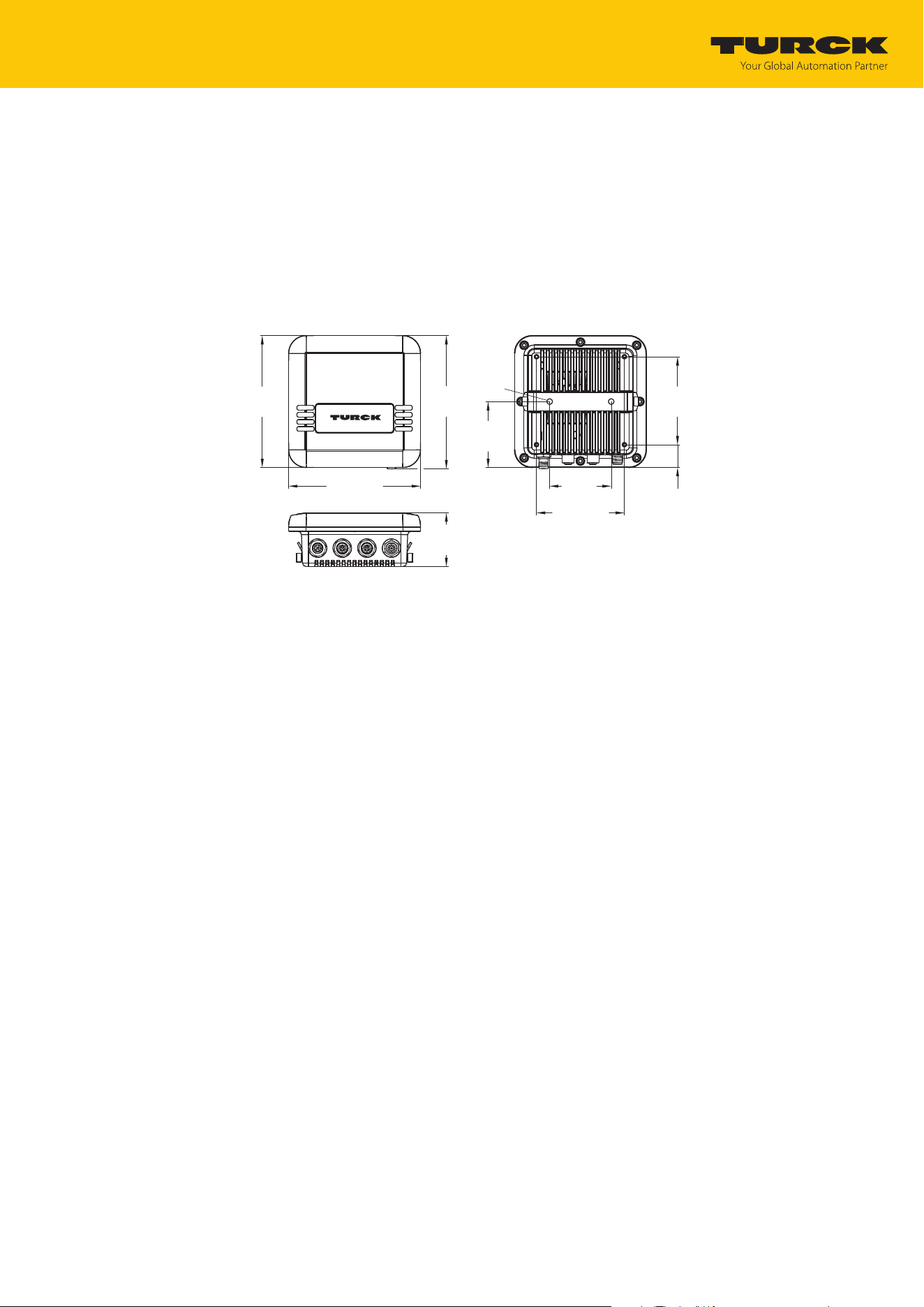
mm [Inch]
150
[5.91]
150 [5.91]
100 [3.94]
100
[3.94]
26
[1.02]
151.3
[5.96]
60.9
[2.40]
75
[2.95]
Ø 6.5
[0.26]
70
[
2.76]
Fig.1: Dimensions – TN-UHF-Q150…
4.1.1 Indication elements
The device has the following LED indicators:
n Power supply
n Group and bus errors
n Status
n Diagnostics
4.2 Properties and features
n Universal interface offers interoperability
n Supports security mechanisms and authentication
n Rectangular, height 150 mm
n Active front face, UV-resistant
n Connection for a passive UHF RFID antenna
n 0.5 W (ERP) maximum output power
n PROFINET device, EtherNet/IP device or Modbus TCP client/server
n Data interface “U” for convenient use of the RFID functionality
n Close-to-control integration in PLC systems without the use of a special function module
n Integrated web server
n LEDs and diagnostics

Product description
Functions and operating modes
TURCK GmbH | T +49 208 4952-0 | [email protected] | www.turck.com
V02.00 | 2025/09 | 10
4.3 Operating principle
The readers are used for contactless data exchange with tags. For this the controller sends com-
mands and data via the interface to the reader and receives the corresponding response data
from the reader. The reading of the IDs of all RFID tags in the read area and the writing of an
RFID tag with a specific production date are examples of typical commands. To communicate
with the tag, the data of the reader is coded and transferred via an electromagnetic field, which
at the same time supplies the tags with power.
A reader contains a transmitter and a receiver, an interface to the interface module and a coup-
ling element (coil and dipole antenna) for communicating with the tag. Electromagnetic wave
propagation is used for the transmission between reader and tag on devices for the UHF range.
IC
Tag
UHF: electromagnetic wave
Reader
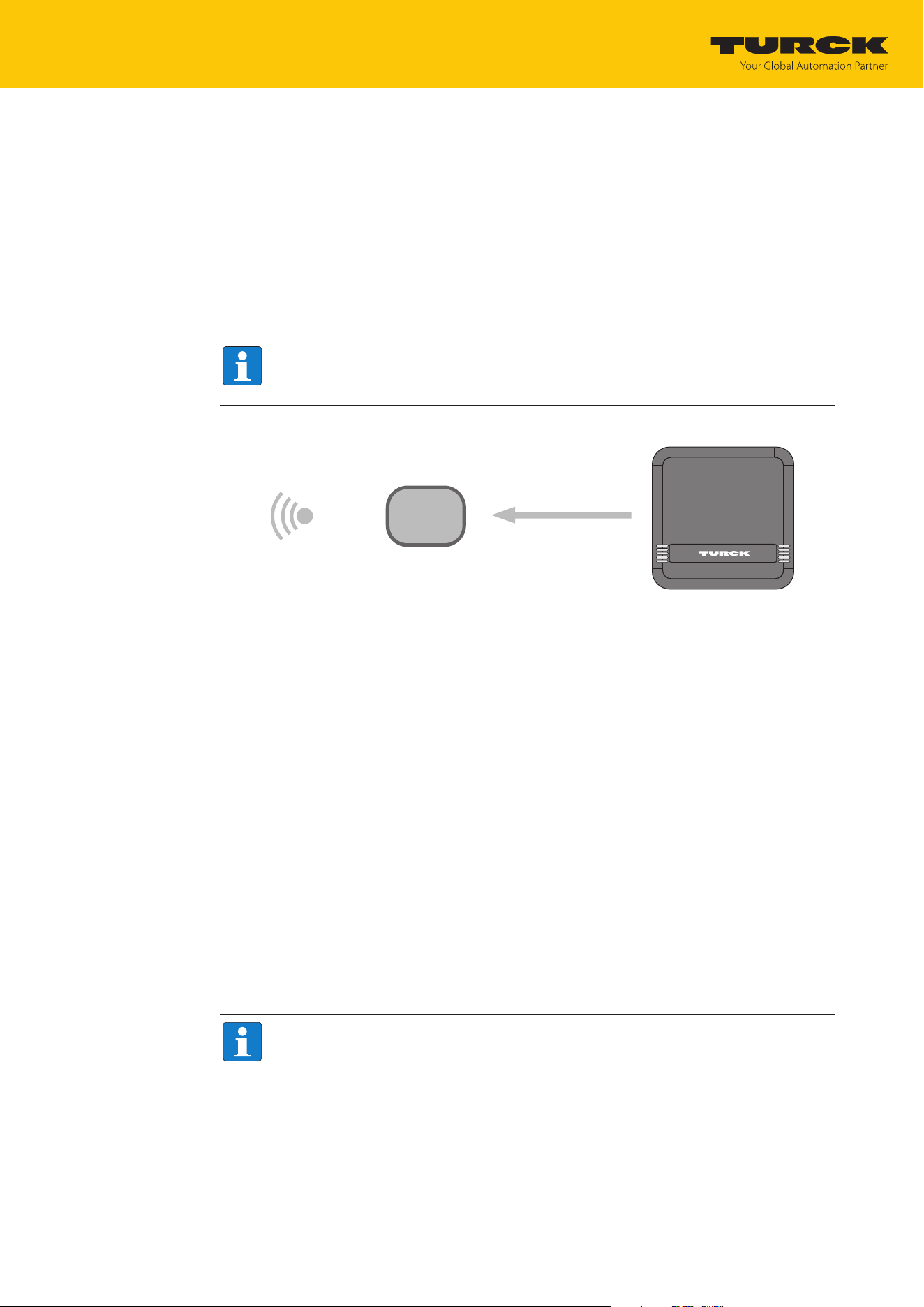
Fig.2: Operating principle of UHF-RFID
The antenna of the reader generates electromagnetic waves. This produces a transmission win-
dow as a so-called air interface in which the data exchange with the tag takes place. The size of
the transmission window depends on the combination of readers and tags, as well as on the
relevant environmental conditions.
Each reader can communicate with a number of tags. This requires the reader and the tag to
operate in the same frequency range. Depending on their power and the frequency in use, the
devices have a range of a few millimeters up to several meters. The specified maximum dis-
tance between the read/write heads represents values measured under laboratory conditions,
free from any influences caused by surrounding materials. Attainable distances may vary due to
component tolerances, mounting conditions, ambient conditions and influences caused by
surrounding materials (especially metal and liquids).
4.4 Functions and operating modes
The device enables passive UHF tags to be read and written in single- and multi-tag operation.
To do this, the device forms a transmission zone. The size and expansion of this zone may vary
on account of several conditions, for example the tags used and the application conditions. The
maximum distance permitted between the read/write heads is outlined in the data sheets. The
device can be extensively tested, configured and parameterized from a PC using the software
tools.
The integrated RFID interface transfers data between the RFID level and the control level.
Various commands can be performed with the device, such as inventory (single-tag and multi-
tag applications), read, write and password protection. Additional functions are provided to op-
timize the speed, for self-triggering of the system and for backup and recovery. Each channel
can transmit 128 bytes per read or write cycle to the controller. To transfer more than
128bytes, the data must be fragmented.

Product description
Functions and operating modes
TURCK GmbH | T +49 208 4952-0 | [email protected] | www.turck.com
V02.00 | 2025/09 | 11
4.4.1 Operating frequency
The TURCK UHF system operates at country-specific operating frequencies between the tags
and the readers. These national operating frequencies for UHF are the frequency ranges that
are individually specified by the national regulation bodies.
For example, the operating frequencies of the devices in the UHF band are 865.6…867.6MHz
for Europe and 902…928MHZ for the USA. The UHF readers can only be used in the particular
designated regions and must not be commissioned outside these regions. Since UHF tags do
not emit their own radio waves, they may be used worldwide.
In order to achieve the biggest possible communication range, TURCK offers tags which are op-
timally tuned to country-specific frequency bands. Alternatively, broadband multi-area tags are
also available for international use.
The different TURCK readers support the following operating frequencies:
n 920…926MHz (e.g. Australia and New Zealand)
n 915…928MHz (e.g. Brazil)
n 920.5…924.5MHz (e.g. China and Thailand)
n 865.6…867.6MHz (e.g. Europe, Türkiye, India)
n 916.7…920.9MHz (e.g. Japan)
n 917…920.8 MHz (e.g. Korea)
n 919…923MHz (e.g. Malaysia)
n 902…928MHz (e.g. USA, Canada, Mexico)
n 920…925MHz (e.g. Singapore)
All the country-specific details concerning UHF, such as frequency band, power supply, and any
national regulations are available at:
https://www.gs1.org/docs/epc/uhf_regulations.pdf
For more detailed information please contact the regulation authorities of the country where
you wish to use the UHF RFID system.
HF RFID systems can be operated in parallel with UHF RFID systems in a single system.
4.4.2 Combination of UHF readers and tags
The UHF readers form a transmission zone, the size of which may vary depending on the com-
bination of reader and tag used. The listed maximum read/write distances only represent typ-
ical values under laboratory conditions without the effect of materials. The achievable dis-
tances may be different due to component tolerances, mounting location in the application,
ambient conditions and the effect of materials (particularly metal).
For this reason, the application must be tested in all cases under real conditions (particularly
with read and write operations in motion).
4.4.3 Multiprotocol function
The device can be used in the following Ethernet protocols:
n PROFINET
n EtherNet/IP
n Modbus TCP

Product description
Functions and operating modes
TURCK GmbH | T +49 208 4952-0 | [email protected] | www.turck.com
V02.00 | 2025/09 | 12
4.4.4 Data transfer to the PLC
Each channel can transmit 128 bytes per read or write cycle. To transfer more than 128bytes,
the data must be fragmented. The amount of data transferred per read or write cycle can be set
as follows for different Ethernet protocols:
PROFINET EtherNet/IP Modbus TCP
n 16 bytes
n 32 bytes
n 64 bytes
n 128 bytes
(default setting)
n 16 bytes
n 64 bytes
n 128 bytes
(default setting)
n 128 bytes (factory set)
Adjustable fragment size:
n 16 bytes
n 32 bytes
n 64 bytes
n 128 bytes
(default setting)
4.4.5 RFID channels — operating modes
Two different data interfaces can be selected for the RFID channels:
n UHF compact: Transfer of up to 128bytes possible, recommended for single tag applications
n UHF extended: Transfer of more than 128bytes possible, recommended for multi-tag applic-
ations
4.4.6 RFID commands
The device can perform the following commands and functions. A complete description of the
commands is provided under "Settings."
n Idle
n Inventory
n Read
n Write
n Write and Verify
n Continuous Mode
n Read data from buffer (cont. mode)
n Stop Continuous (Presence Sensing) Mode
n UHF Continuous Presence Sensing Mode
n Read/write head identification
n Get UHF read/write head status/error
n Tag info
n Direct read/write head command
n Set read/write head password
n Reset read/write head password
n Set tag password
n Set tag protection
n Deactivate tag irrevocably (kill)
n Restore UHF read/write head settings
n Backup UHF read/write head setting
n Reset

Product description
Technical accessories
TURCK GmbH | T +49 208 4952-0 | [email protected] | www.turck.com
V02.00 | 2025/09 | 13
4.4.7 Loop counter function
The loop counter function is provided for rapid command processing. The loop counter func-
tion only requires two PLC cycles to execute a command repeatedly (flow chart see [}150]).
This increments the loop counter to execute a command repeatedly. At least four PLC cycles
are required in conventional command processing. In order to execute a command repeatedly
with conventional command processing, a command has to be reset and then set again. The
loop counter function is provided for special commands. If the command was successfully ex-
ecuted, the command code is output in the response data.
4.5 Technical accessories
Optionally available accessories for mounting, connecting and parameter setting can be found
in the TURCK product database at www.turck.com. Accessories are not supplied with the
device.
Installing
TURCK GmbH | T +49 208 4952-0 | [email protected] | www.turck.com
V02.00 | 2025/09 | 14
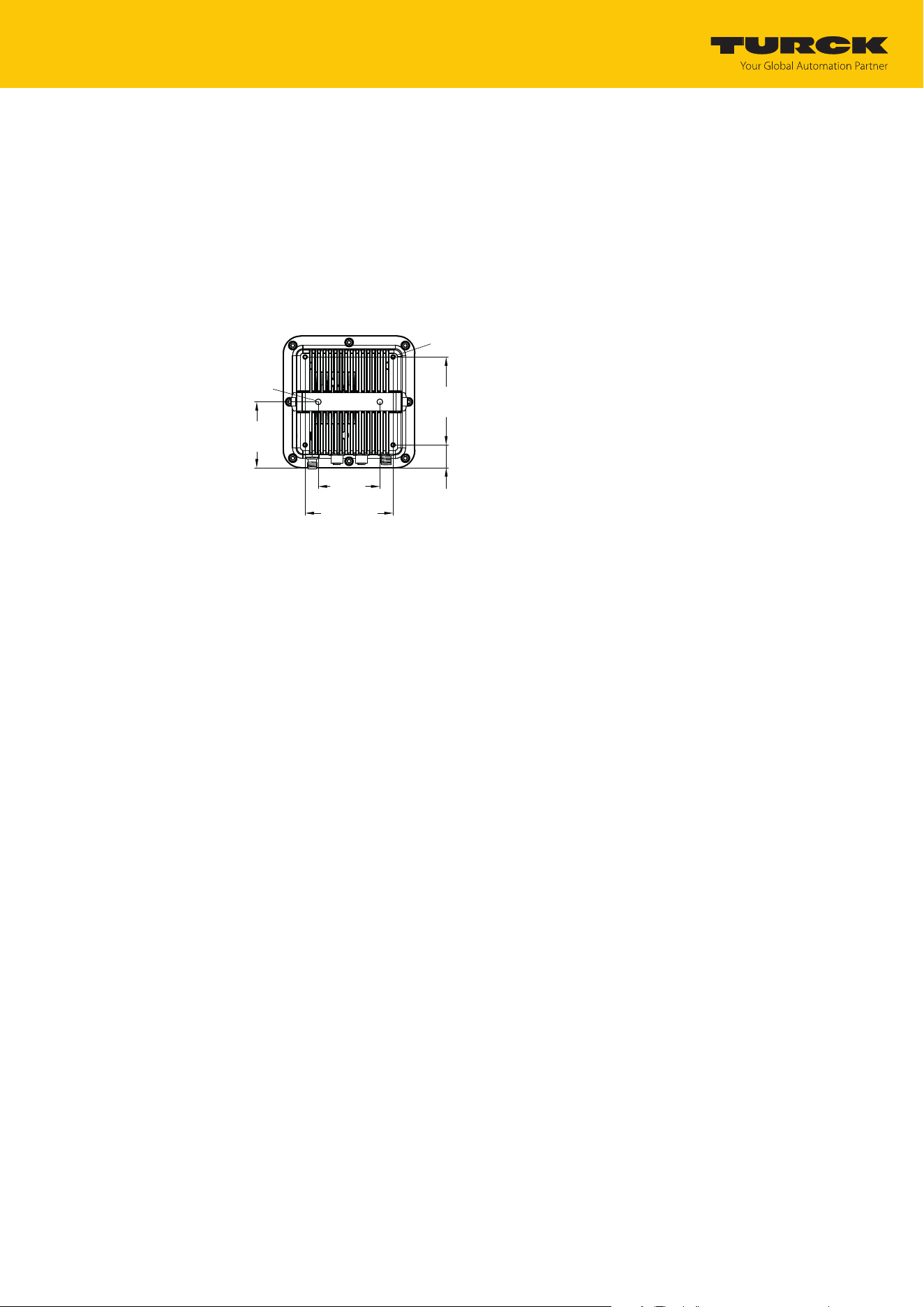
5 Installing
The device is designed for mounting on a bracket based on the VESA 100 × 100 standard. The
device is provided with four M4 threaded holes spaced 100 mm apart (horizontally and
vertically). The maximum length of the screws is 8mm plus the thickness of the VESA bracket.
The devices can be mounted in any position.
Fasten the device with four M4 screws to a bracket in accordance with VESA 100 x 100.
100 [3.94]
100
[3.94
]
26
[1.02]
75
[2.95]
Ø 6.5
[0.26]
70
[2.76]
4 × M4
Fig.3: Rear view – TN-UHF-Q150…

Connecting
Connecting devices to Ethernet
TURCK GmbH | T +49 208 4952-0 | [email protected] | www.turck.com
V02.00 | 2025/09 | 15
6 Connecting
6.1 Connecting devices to Ethernet
The device has two 4-pin M12 female connectors for connection to an Ethernet system.
Fig.4: M12 Ethernet connector
Connect the device to Ethernet in accordance with the pin assignment below
(max. tightening torque: 0.8Nm).
v
4
1
3
2
ETH
1 =
TX +
2 = RX +
3 = TX –
4 = RX –
flange = FE
Fig.5: Pin assignment for Ethernet connections
Connecting
Connecting the external antenna
TURCK GmbH | T +49 208 4952-0 | [email protected] | www.turck.com
V02.00 | 2025/09 | 16
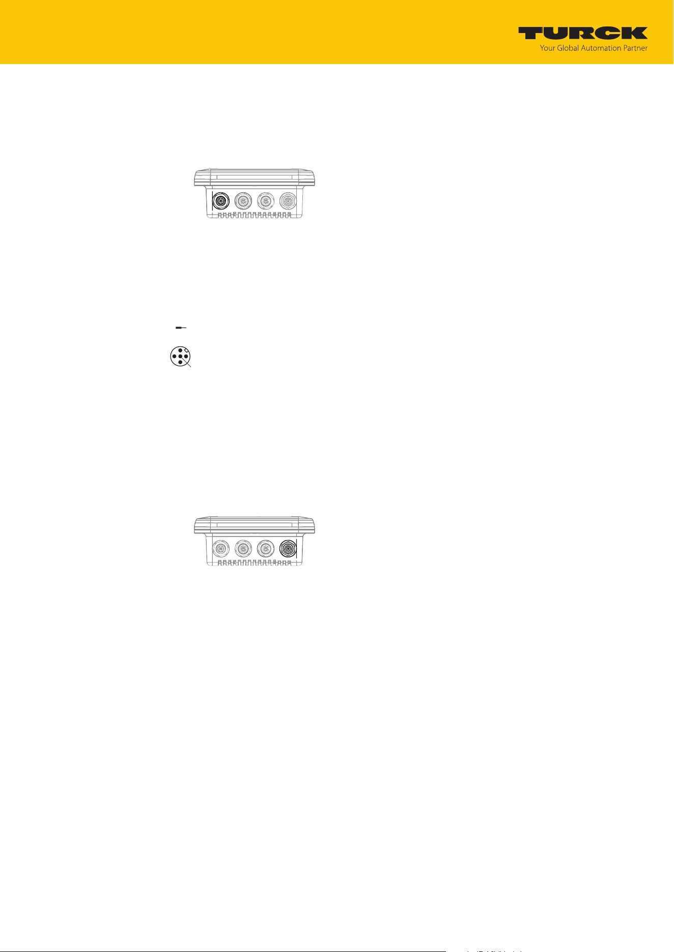
6.2 Connecting the power supply
The device has a 5-pin M12 connector for connecting to the power supply.
Fig.6: M12 connector for connecting to the power supply
Connect the device to the power supply in accordance with the pin assignment below
(max. tightening torque: 0.8Nm).
1 = V1
2 = n.c
.
3 = GND
4 = n.c.
5 = PE
3
2
1
5
4
24 VDC
Fig.7: Pin assignment for the power supply connection
6.3 Connecting the external antenna
The device has an RP-TNC female connector for connecting an external antenna. The input im-
pedance is 50Ω.
Fig.8: RP-TNC female connector for connecting an external antenna
Connect the external antenna to the device using an RP-TNC antenna cable (max. tight-
ening torque: 0.8Nm).
Commissioning
Parameterizing the reader using the web server
TURCK GmbH | T +49 208 4952-0 | [email protected] | www.turck.com
V02.00 | 2025/09 | 17
7 Commissioning
7.1 Parameterizing the reader using the web server
The integrated web server can be used to set the devices and send commands to the devices.
In order to be able to open the web server with a PC, the device and the PC must be in the
same IP network.
7.1.1 Opening a web server
The web server can be opened from a web browser or from the TURCK Automation Suite (TAS).
Accessing the web server via TAS is described in the section entitled ”Adjusting network set-
tings.”
7.1.2 Editing settings in the web server
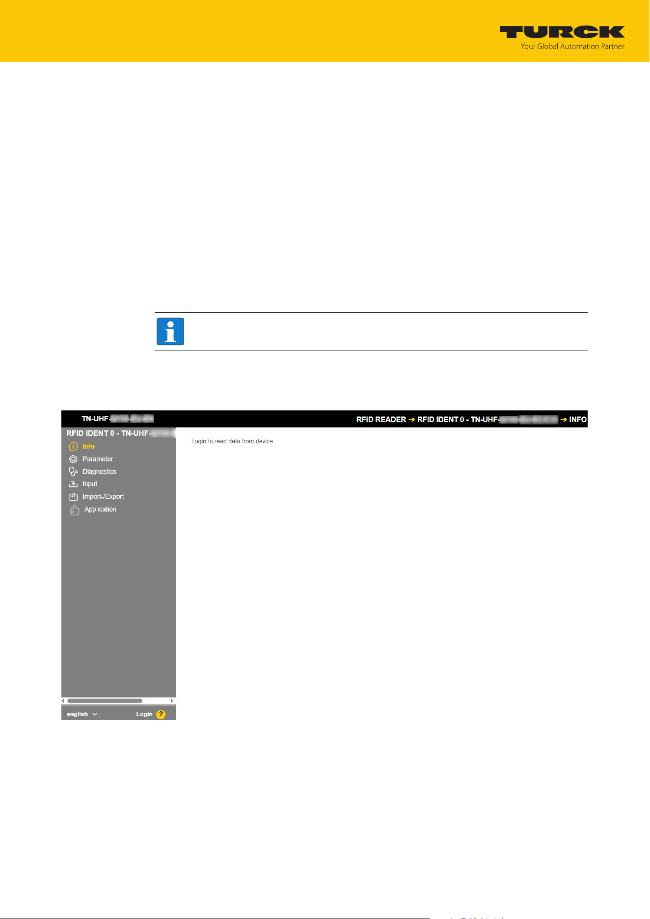
A login is required to edit settings via the web server. The default password is "password".
NOTE
TURCK recommends changing the password after the first login for security reasons.
Open the device’s web server.
Enter Username and Password.
Click Login
Fig.9: Web server — login
Commissioning
Parameterizing the reader using the web server
TURCK GmbH | T +49 208 4952-0 | [email protected] | www.turck.com
V02.00 | 2025/09 | 18
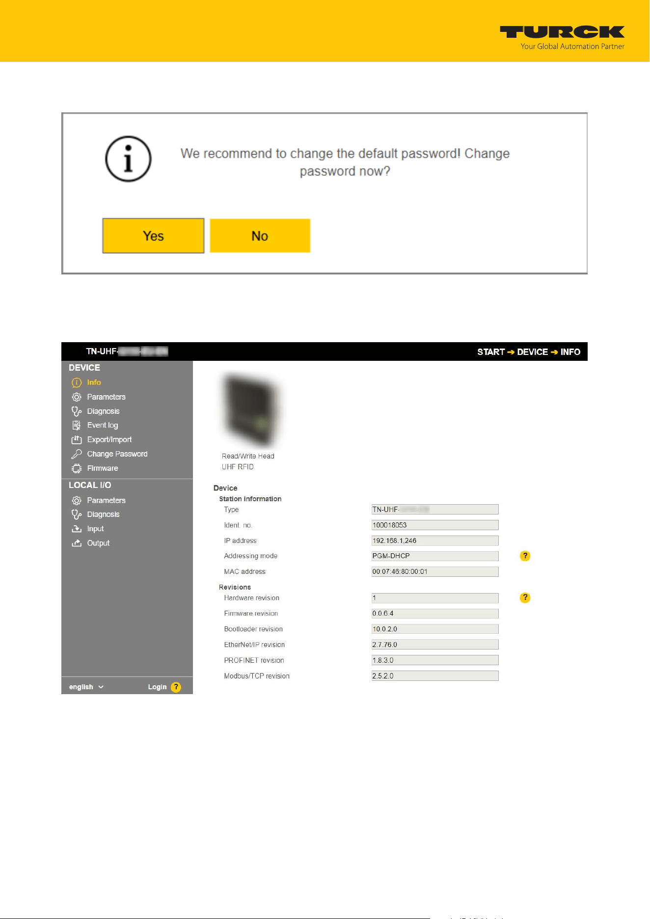
Change the password after you log in.
Fig.10: Web server — password change dialog
After you log in, the home page is displayed with the device information.
Click RFID READER to display and set the device parameters.
Fig.11: Web server — RFID Reader — Info
Commissioning
Parameterizing the reader using the web server
TURCK GmbH | T +49 208 4952-0 | [email protected] | www.turck.com
V02.00 | 2025/09 | 19
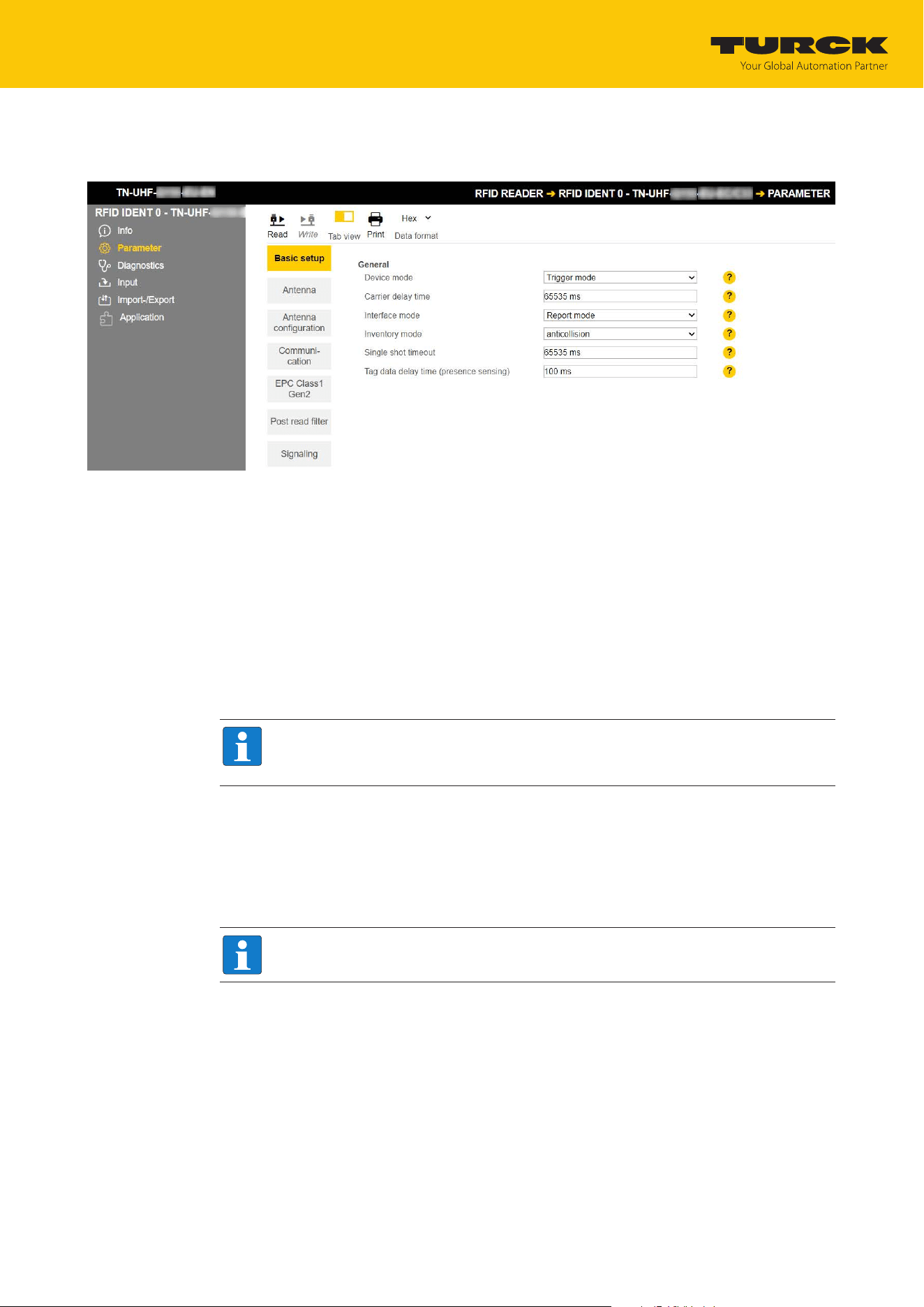
Click Parameter in the navigation bar on the left of the screen.
a All parameters of the device are displayed.
Fig.12: Web server — RFID Reader — Parameter
The following setup windows can be called up:
n Basic setup
n Antenna
n Antenna configuration
n Communication
n EPC Class1 Gen2
n Post read filter
n Signaling
Set the parameters: Click Write.
NOTE
While a parameter is being set, the ERR LED lights up red and automatically turns
green.
7.1.3 Multiplex operation
In multiplex operation, several antennas can be controlled or switched on in sequence. The ex-
ample below shows the activation of the antennas in sequence. The multiplex operation can
consist of up to 16 sequences and can be used, for example, for gate applications.
A login is required to edit settings via the web server. The default password is "password".
NOTE
TURCK recommends changing the password after the first login for security reasons.
Open the device’s web server.
Enter Username and Password.
Click Login
Commissioning
Parameterizing the reader using the web server
TURCK GmbH | T +49 208 4952-0 | [email protected] | www.turck.com
V02.00 | 2025/09 | 20
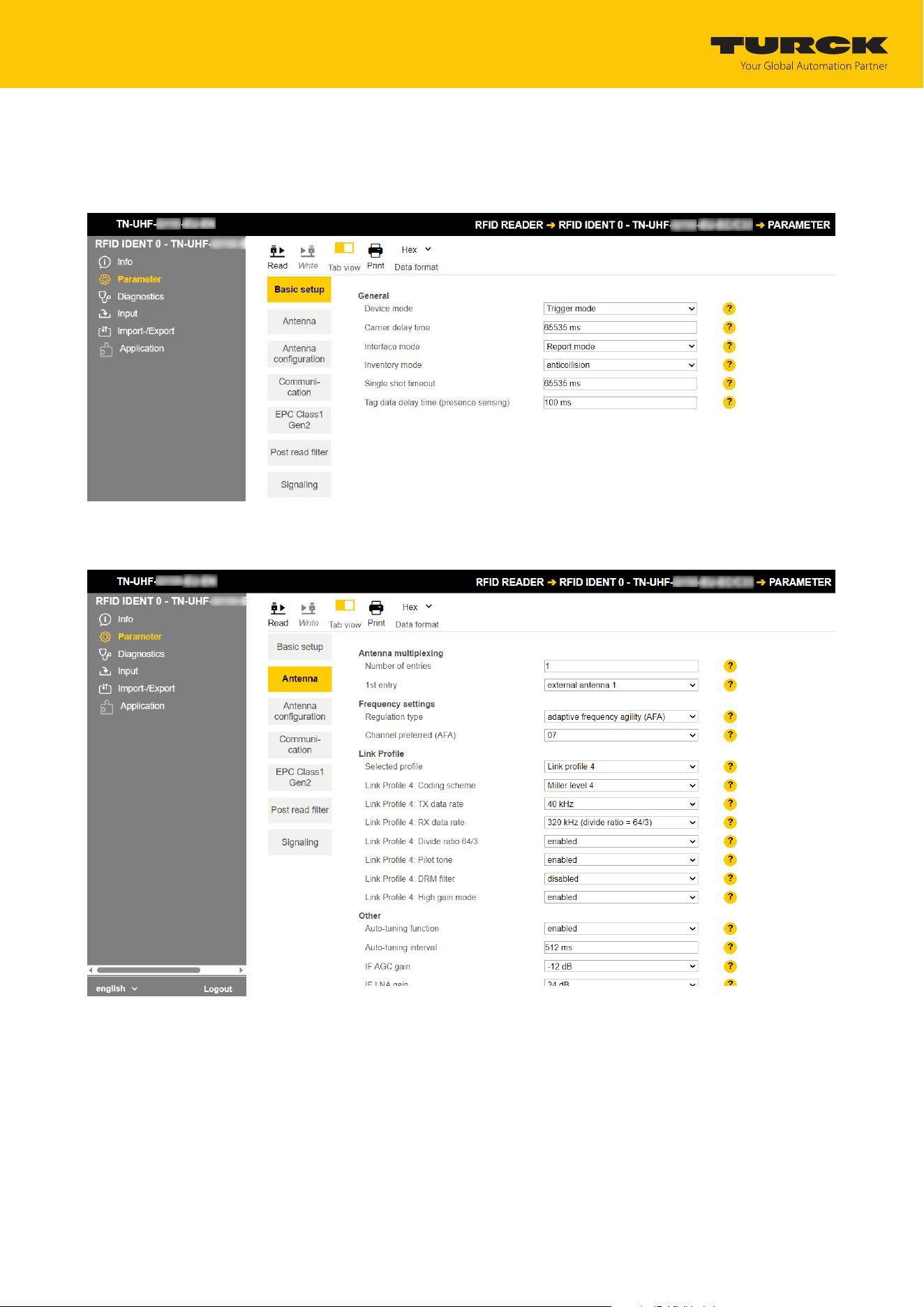
Example: Configuring multiplex operation
Select RFID READER.
Select Parameter.
Fig.13: RFID Reader — Parameter
Select Antenna.
Fig.14: RFID Reader — Parameter — Antenna
Commissioning
Parameterizing the reader using the web server
TURCK GmbH | T +49 208 4952-0 | [email protected] | www.turck.com
V02.00 | 2025/09 | 21
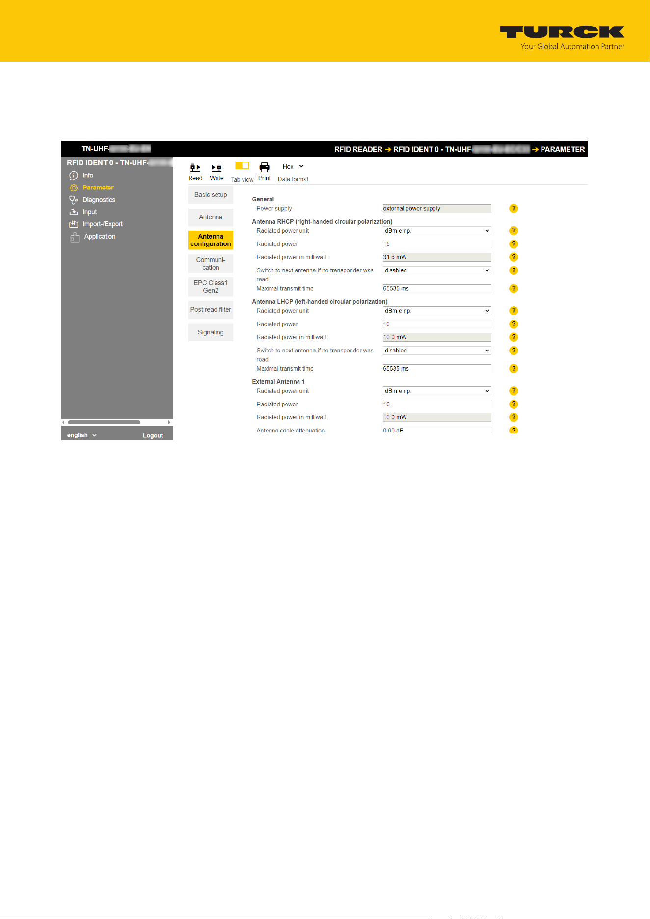
Under Antenna multiplexing, enter the number of antennas in the Number of entries
field.
Select Antenna configuration.
Fig.15: RFID reader — Parameter — Antenna configuration
For each antenna, enter in the Maximum transmit time field the amount of time for
which that antenna should remain active.
Commissioning
Parameterizing the reader using the web server
TURCK GmbH | T +49 208 4952-0 | [email protected] | www.turck.com
V02.00 | 2025/09 | 22
7.1.4 Setting antenna power
The antenna power of the reader can be set for the specific application. The radiated power can
be entered directly for the integrated antenna. The power must be calculated for external an-
tennas.
The following parameters must be used to calculate the radiated power (P
ERP
):
P
cond
Power to be output at the TNC female connector of the reader
dB Cable attenuation
G
HW
Antenna gain of the external antenna
NOTE
Refer to the data sheets of the components used for the cable attenuation and an-
tenna gain.
BUS
ERR
RUN
APP
LA
M
PWR
RFON
DATA
DIAG
USER
Conducted
po
wer
P
cond
Cable
attenuation
dB
Antenna
gain
G
HW
Radiated
power
P
ERP
Antenna
Fig.16: Power calculation – Relevant variables (schematic representation)
The power can be calculated with the following formula:
P
ERP
= G
HW
- dB + P
cond
Setting antenna power – Restrictions of radio regulations
Some national regulations restrict the degree of freedom available for creating an RFID system.
You as the operator are responsible for ensuring that regulations are observed.
n ETSI
– Radiated power P
ERP
: max. 33 dBm ERP
n FCC
– Radiated power P
ERP
: max. 36 dBm EIRP
– P
cond
: Max. 30 dBm with antenna gain G
HW
≤ 6 db
NOTE
The web server uses an exclamation point to identify invalid configurations. A trans-
mission to the device is prevented.

Commissioning
Parameterizing the reader using the web server
TURCK GmbH | T +49 208 4952-0 | [email protected] | www.turck.com
V02.00 | 2025/09 | 23
Calculating radiated power
The effective radiated power (ERP) is the power that is radiated from an antenna into free
space. To make it possible to compare the technical properties of different antenna, the power
specifications given are always in relation to a reference antenna.
n EIRP = equivalent isotropic radiated power (reference: isotropic antenna)
n ERP = effective radiated power (reference: with the length of λ/2)
The radiated power can be stated in watts or in dBm. The following table shows approximate
values as a guide for converting between dBm and mW:
dBm mW dBm mW dBm mW dBm mW
1 1.25 9 8 17 50 25 316
2 1.6 10 10 18 63 26 400
3 2 11 13 19 80 27 500
4 2.5 12 16 20 100 28 630
5 3 13 20 21 125 29 800
6 4 14 25 22 160 30 1000
7 5 15 32 23 200 … …
8 6 16 40 24 250 33 2000
The formula for calculating the exact values is: dBm = 10 × lg (P/1 mW)
Converting antenna gain
The antenna gain can be specified in the following units:
dBd Antenna gain in relation to a dipole
dBi Antenna gain in relation to an isotropic radiator (linear)
dBic Antenna gain in relation to an isotropic radiator (circular)
The different units can be converted as follows:
n G
HW
= dBd
n G
HW
= dBi - 2.15
n G
HW
= dBic - 5.15
Commissioning
Parameterizing the reader using the web server
TURCK GmbH | T +49 208 4952-0 | [email protected] | www.turck.com
V02.00 | 2025/09 | 24
Setting the power for external antennas
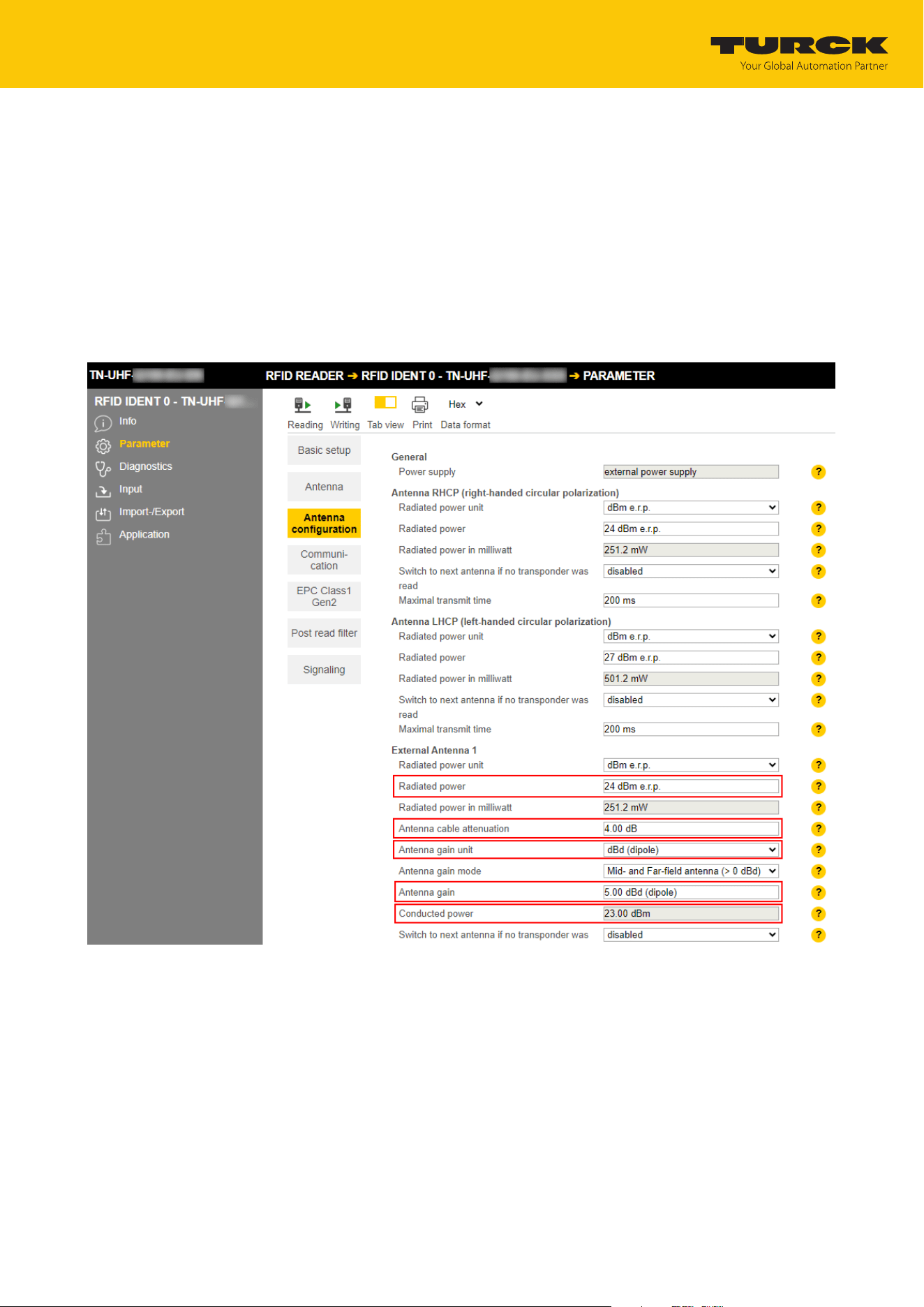
Set the radiated power under External Antenna 1 Ò Radiated power (here:
24dBme.r.p.).
Refer to the data sheet of the cable used for the cable attenuation.
Enter the cable attenuation at Antenna cable attenuation.
Refer to the data sheet of the external antenna for the antenna gain.
Set the unit for the antenna gain at Antenna gain unit (here: dBd).
Set antenna gain at Antenna gain (here: 5.00).
ð The power at the TNC female connector (P
cond
) is calculated automatically and dis-
played under Conducted power.
Fig.17: Setting the antenna power
Click Accept to save the settings.
Set the power for each additional antenna separately.
Commissioning
Parameterizing the reader using the web server
TURCK GmbH | T +49 208 4952-0 | [email protected] | www.turck.com
V02.00 | 2025/09 | 25
7.1.5 Setting antenna polarization
The antenna polarization can be set via the web server or via TAS. Switching the polarization
makes it possible to change null spots caused by interference. The detection rate can be in-
creased by switching the polarization. Polarization switching is suitable for example in single-
tag applications in particularly metallic environments.
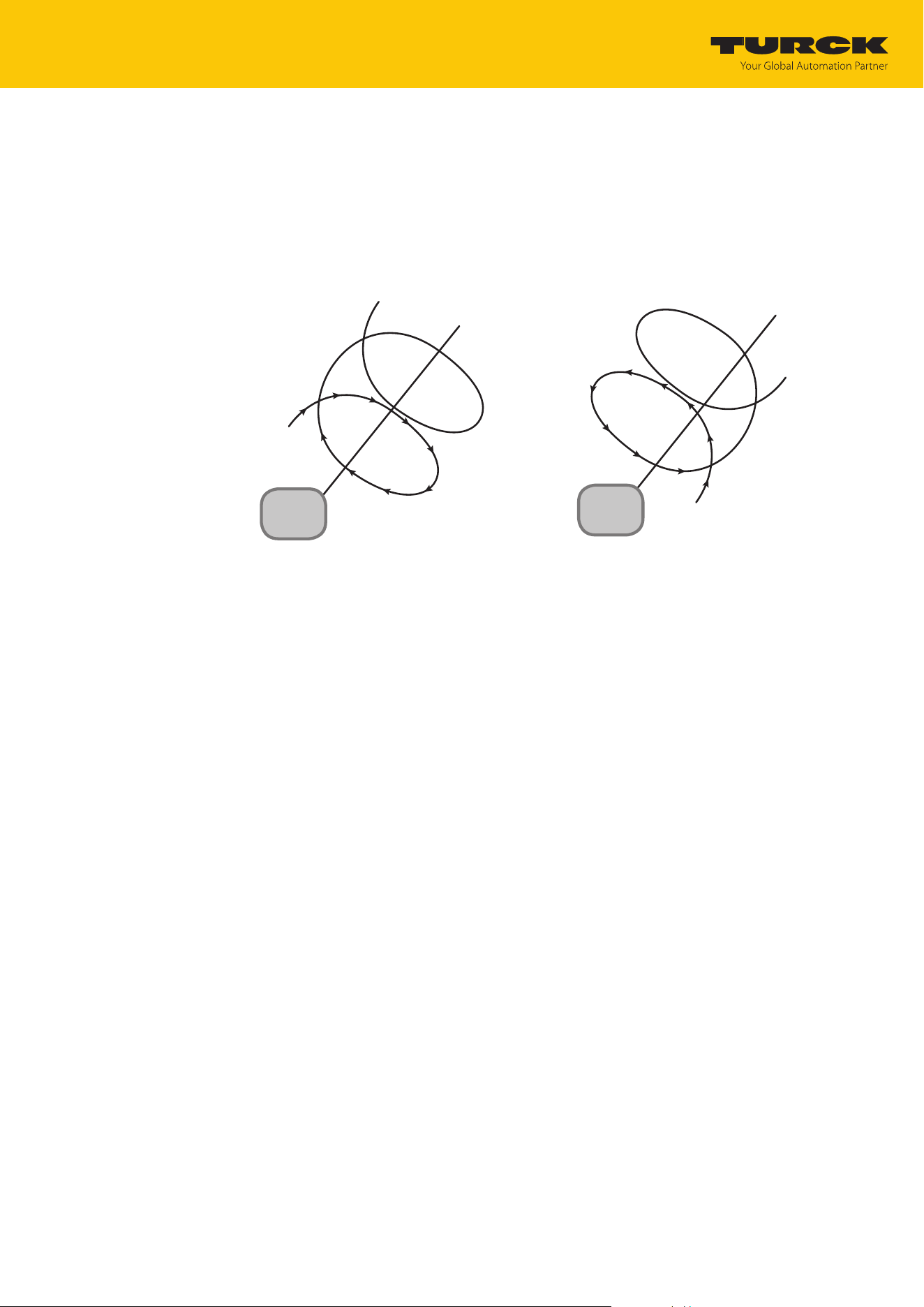
The following graphics schematically illustrate the possibilities of antenna polarization.
ANT
ANT
Fig.18: Antenna polarization circular (RHCP) Fig.19: Antenna polarization circular (LHCP)
Commissioning
Parameterizing the reader using the web server
TURCK GmbH | T +49 208 4952-0 | [email protected] | www.turck.com
V02.00 | 2025/09 | 26
Switching antenna polarization
Polarization switching is activated via the multiplex settings.
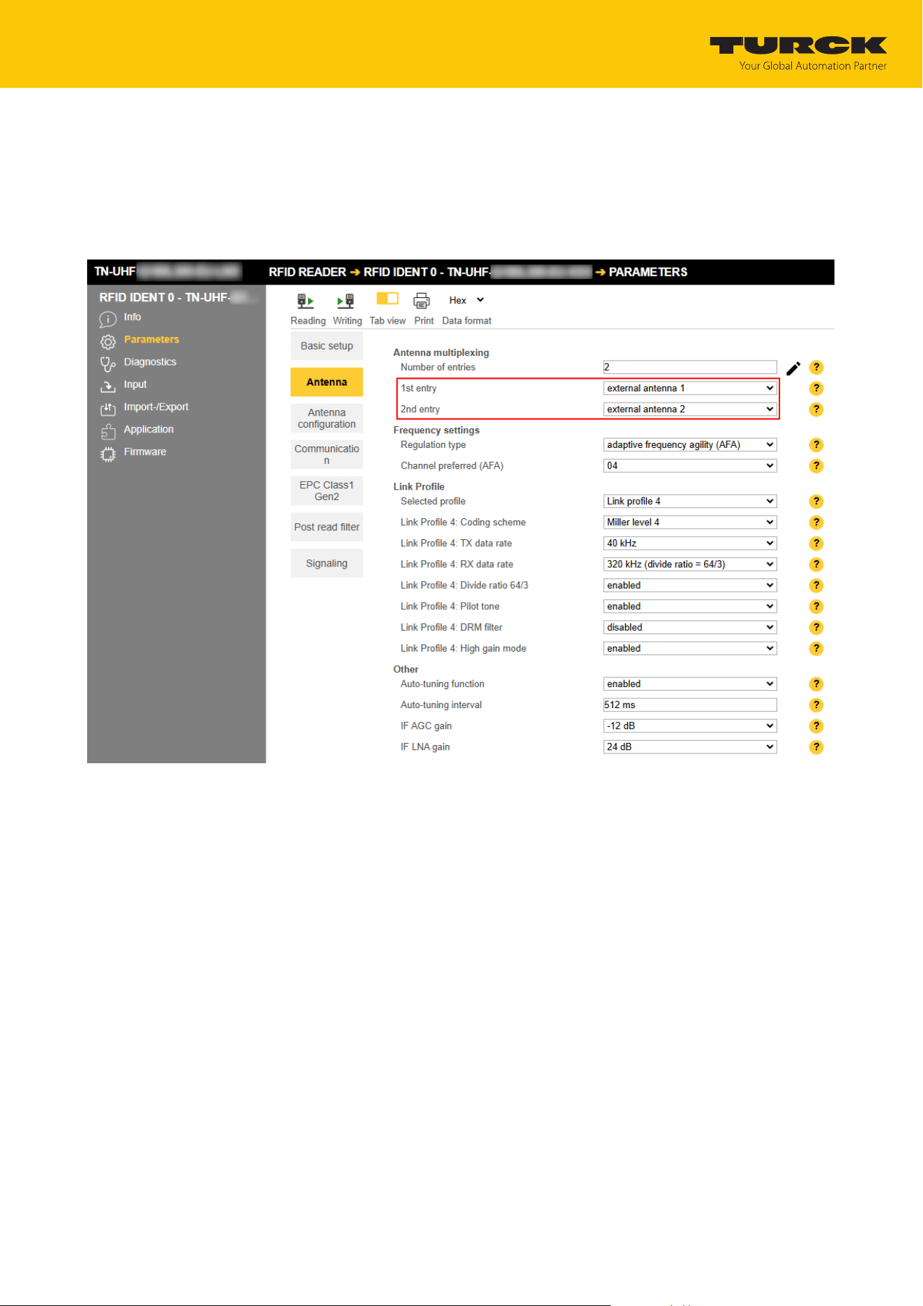
At Antenna Ò Number of entries, set the value 2.
At Antenna Ò 1st entry, set the value antenna RHCP.
At Antenna Ò 2nd entry, set the value antenna LHCP.
Fig.20: Switching antenna polarization
Commissioning
Parameterizing the reader using the web server
TURCK GmbH | T +49 208 4952-0 | [email protected] | www.turck.com
V02.00 | 2025/09 | 27
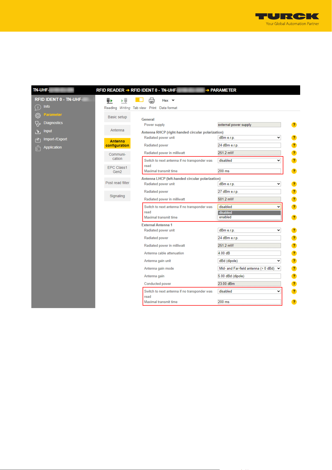
At Antenna configuration Ò Maximal transmit time, set the time up to the polarization
switch or activate the Switch to next antenna if no transponder was read option.
a If the Switch to next antenna if no transponder was read option is activated, the reader
automatically switches after an inventory operation without reading to the next multi-
plex sequence (Entry).
Fig.21: Switching polarization automatically
Commissioning
Parameterizing the reader using the web server
TURCK GmbH | T +49 208 4952-0 | [email protected] | www.turck.com
V02.00 | 2025/09 | 28
7.1.6 Switching on presence sensing mode
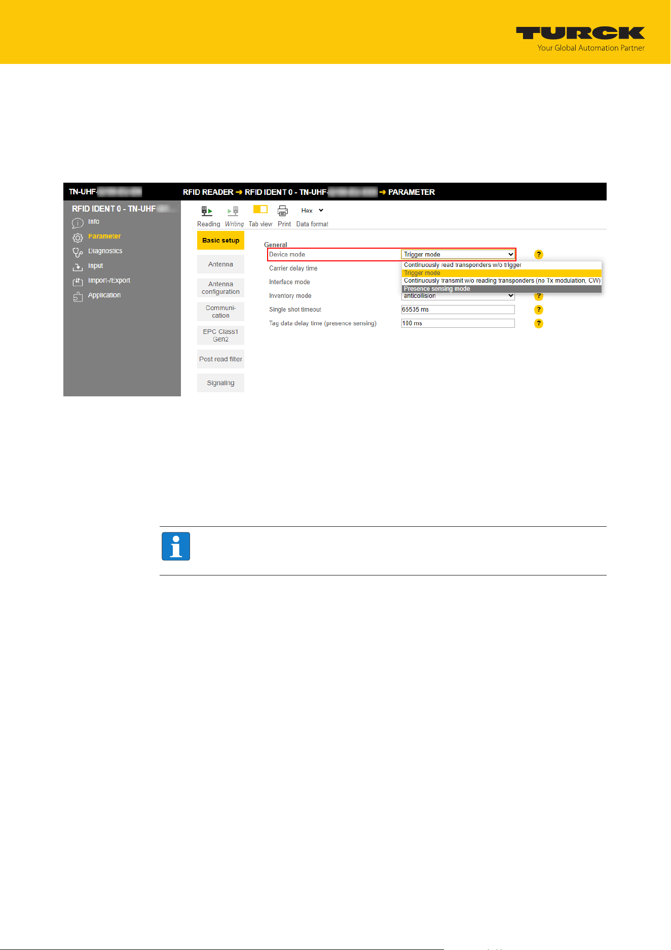
In order to use the Continuous presence sensing mode command, the Presence sensing mode
must be activated in the reader. In the Presence sensing mode, the readers are automatically
switched on as soon as a tag is located in the detection range.
At Basic setup Ò General Ò Device mode, set the Presence sensing mode option.
Fig.22: Switching on presence sensing mode
The Advanced access level allows the Tag data delay time and Carrier delay time parameters
to be set individually.
n Tag data delay time: Time in which the reader searches for a tag. If a tag is found, the field is
switched on. In the Basic access level, the parameter is set by default to 100 ms.
n Carrier delay time: Time until the reader switches off the field after the last read operation.
In the Basic access level, the parameter is set by default to 65535 ms.
NOTE
Report mode is recommended for the RFID test since the read tag information items
appear in the RFID test window and do not have to be polled individually.
Commissioning
Parameterizing the reader using the web server
TURCK GmbH | T +49 208 4952-0 | [email protected] | www.turck.com
V02.00 | 2025/09 | 29
7.1.7 Transferring the RSSI value — communication
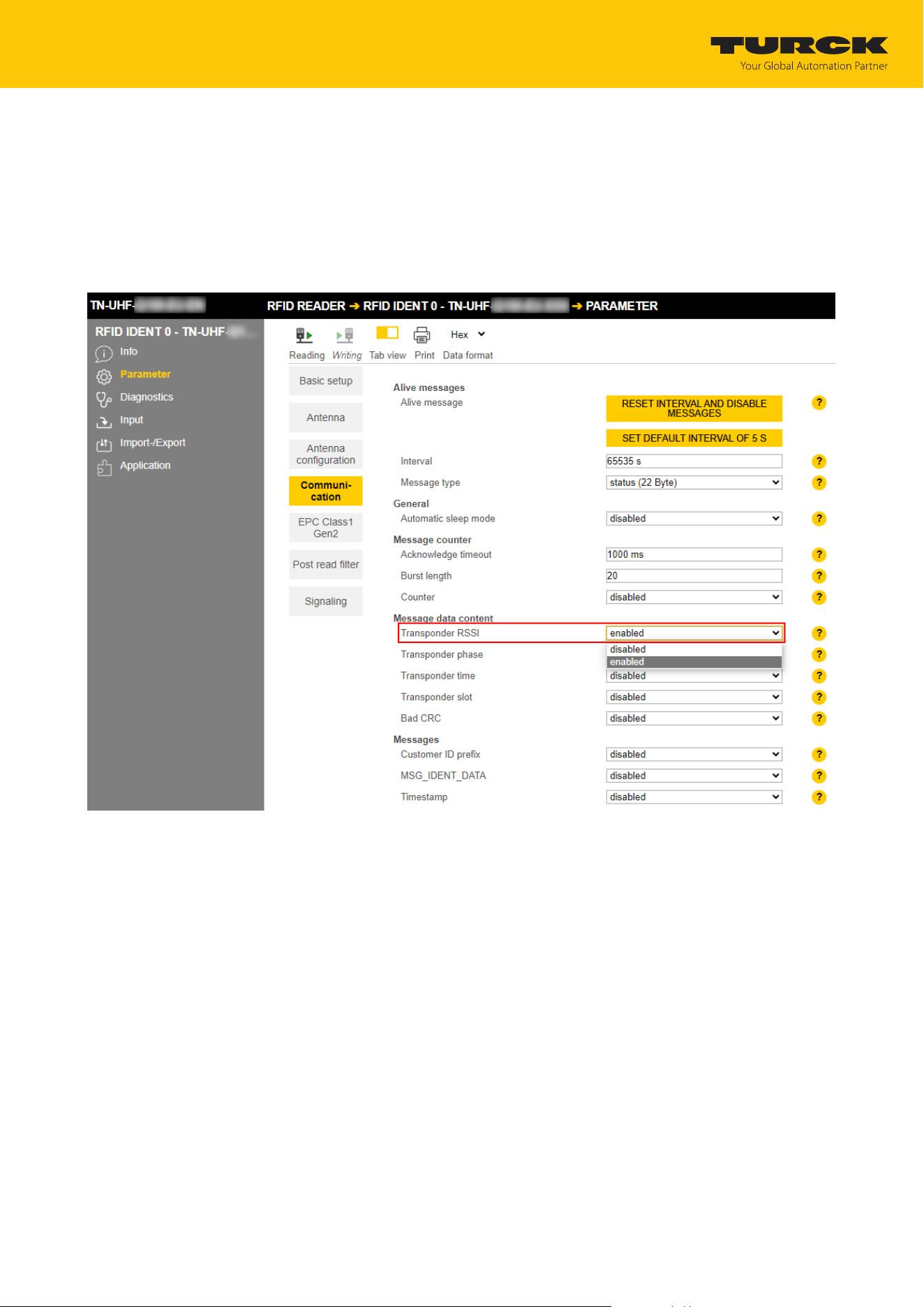
The Communication tab is used to set the parameters for the configuration of the deBus mes-
sages. All parameters and the adjustable values are described in the web server.
Example: Switching on RSSI transmission
Switch on RSSI transmission: At Communication Ò Message data content Ò Transpon-
der RSSI, select the enabled option.
Fig.23: Switching on RSSI transmission
a The RSSI value is displayed with the inventory in the read data.
Commissioning
Parameterizing the reader using the web server
TURCK GmbH | T +49 208 4952-0 | [email protected] | www.turck.com
V02.00 | 2025/09 | 30
7.1.8 Setting the RSSI filter — post read filter
The Post read filter tab enables parameters to be set in order to filter event messages.
The set filters do not reduce the data traffic on the air interface and are not suitable for multi-
tag applications with many tags or high passing speeds. All parameters and the adjustable val-
ues are described in the web server.
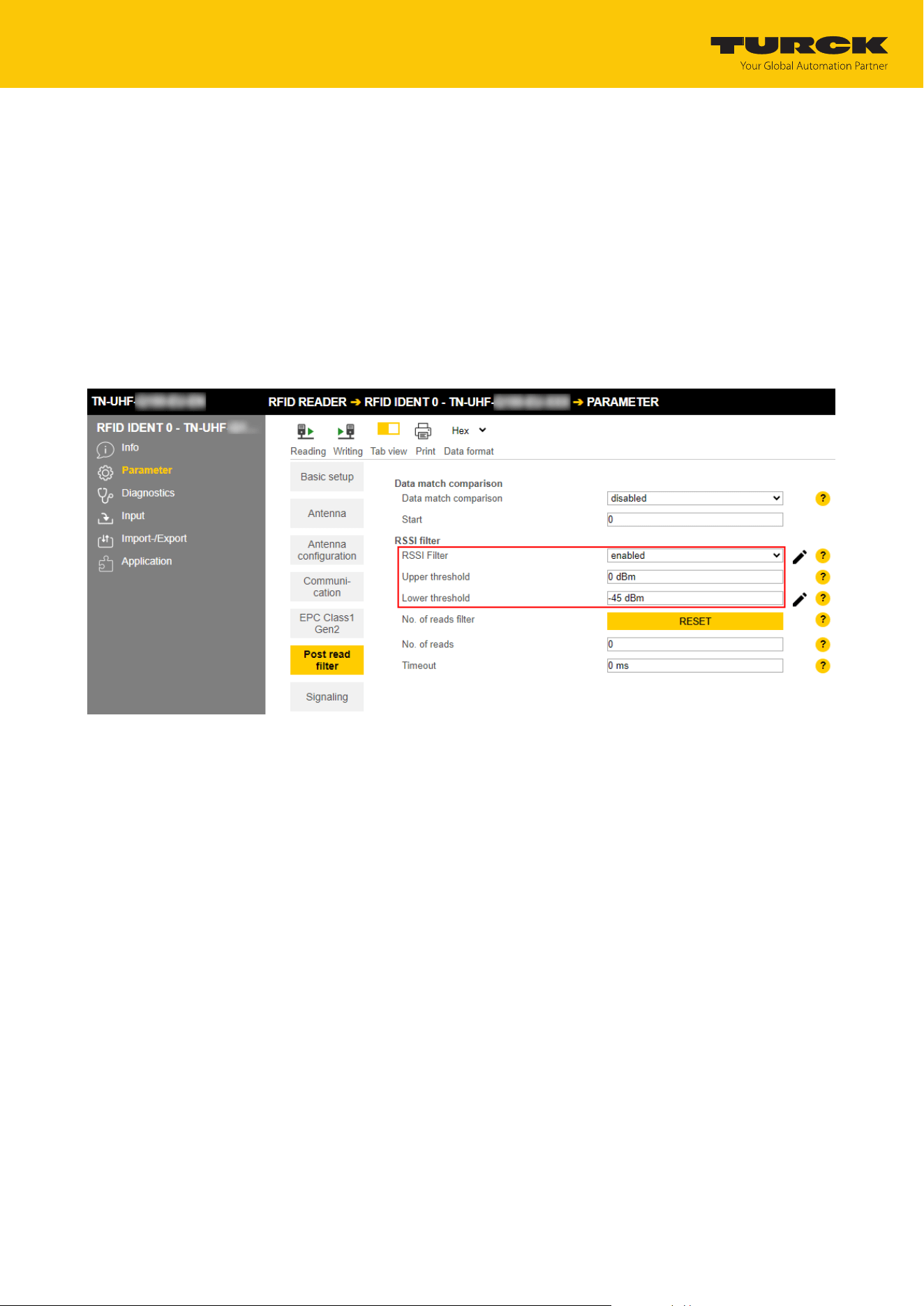
Example: Set the RSSI filter
An RSSI filter makes it possible to prevent unwanted read operations. All read operations with
an RSSI outside of the set limit values are filtered out and not displayed.
At Post read filter Ò RSSI filter, enable the RSSI Filter.
Set the threshold at Post read filter Ò RSSI filter Ò Lower threshold.
Fig.24: Switching on the RSSI filter
a Example: All read operations below an RSSI value of -45 dBm are filtered out.
Commissioning
Testing the reader using the web server
TURCK GmbH | T +49 208 4952-0 | [email protected] | www.turck.com
V02.00 | 2025/09 | 31
7.2 Testing the reader using the web server
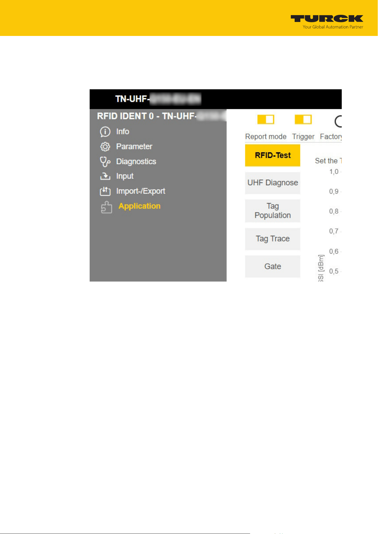
The Application function enables the devices to be tested with the web server.
Click RFID READER Ò Application
Fig.25: Web server — RFID Reader — Application
Commissioning
Testing the reader using the web server
TURCK GmbH | T +49 208 4952-0 | [email protected] | www.turck.com
V02.00 | 2025/09 | 32
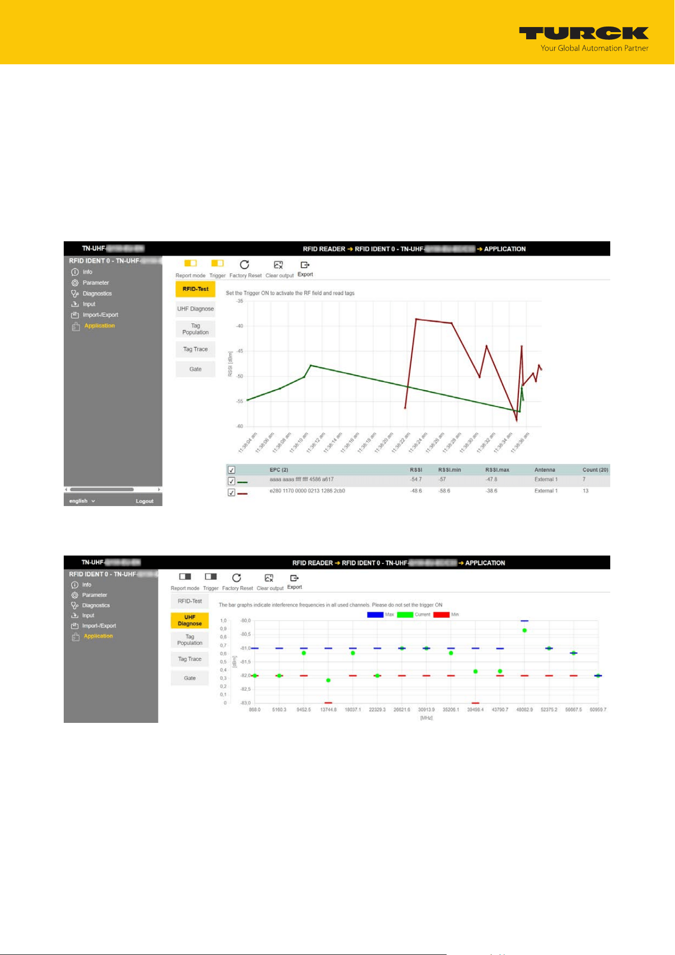
The following items are available in the Application area: RFID Test, UHF Diagnostics, Tag
Population, Tag Trace and Gate:
n RFID-Test: If the trigger is set to ON, the RF field is activated and tags can be read.
n UHF Diagnostics: The diagrams show the interference frequencies of all channels used.
n Tag Population: A tool to determine the radiated power from which all tags can be read.
n Tag Trace: Tool for reading individual tags with curve of signal strength over time.
n Gate: Tool for reading multiple tags (bulk reading)
RFID test allows EPC information from tags to be displayed and read out in single-tag and
multi-tag mode. The received RSSI values are displayed as a curve in relation to time.
Fig.26: Example RFID test
The UHF diagnostics display the current power level being received by the reader per channel.
Fig.27: Example UHF diagnostics
Commissioning
Adjusting network settings
TURCK GmbH | T +49 208 4952-0 | [email protected] | www.turck.com
V02.00 | 2025/09 | 33
7.3 Adjusting network settings
7.3.1 Adjusting network settings via TAS (TURCK Automation Suite)
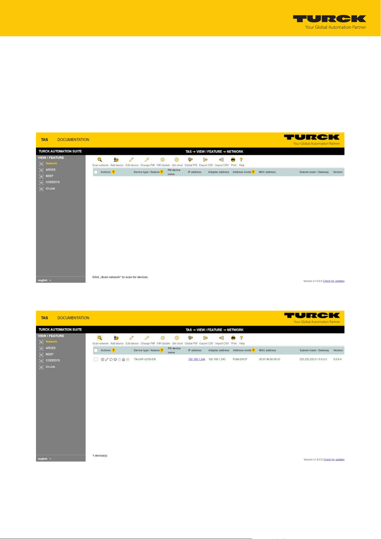
The device is factory set to IP address 192.168.1.254. The IP address can be set via TAS (TURCK
Automation Suite). TAS is available free of charge at www.turck.com.
Connect the device to a PC via the Ethernet interface.
Open TAS.
Click Scan network.
Fig.28: TAS — home screen
ð TAS displays the connected devices.
Fig.29: TAS — found devices
Commissioning
Adjusting network settings
TURCK GmbH | T +49 208 4952-0 | [email protected] | www.turck.com
V02.00 | 2025/09 | 34
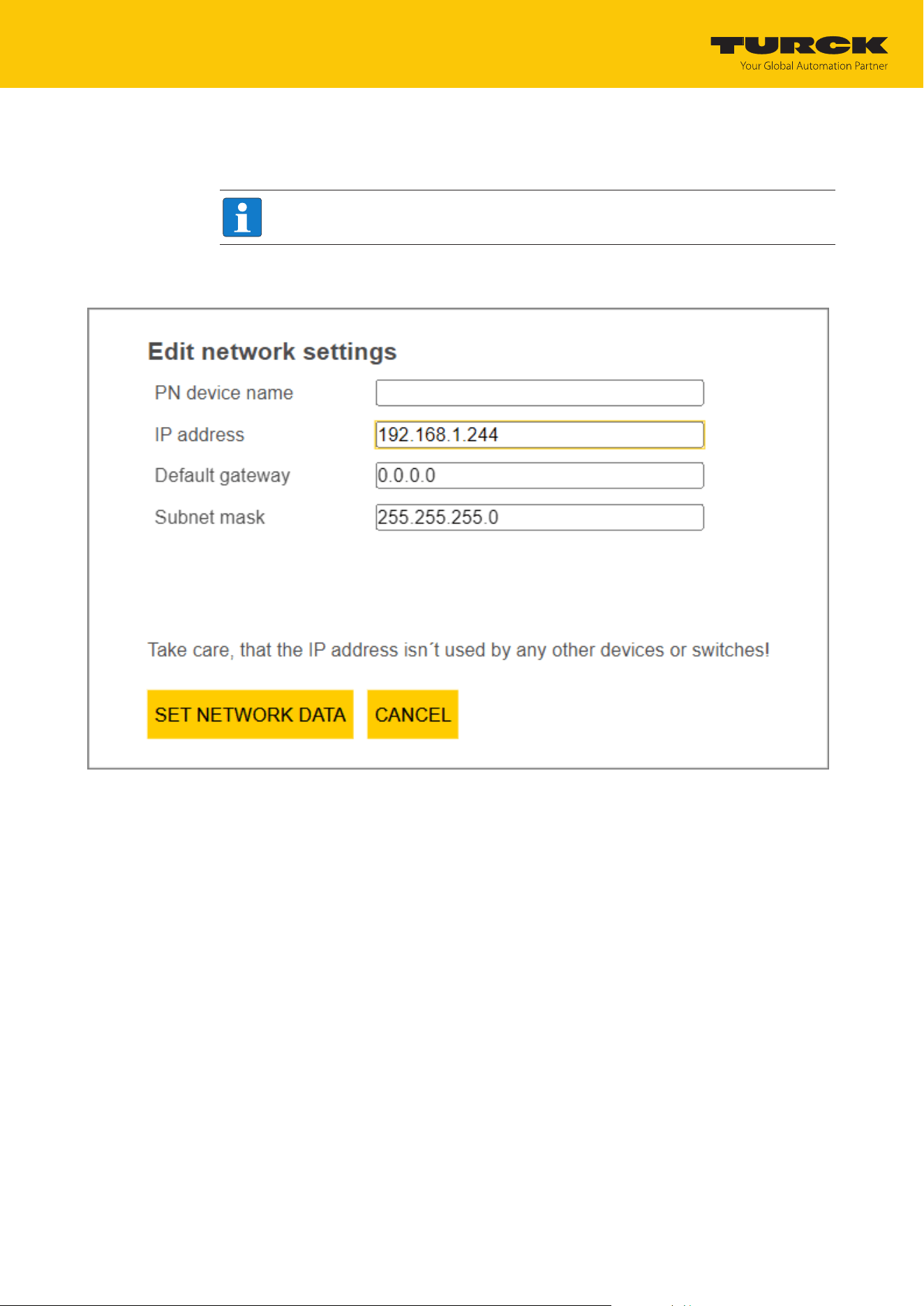
Select the required device (check the checkbox).
Click Edit device.
NOTE
Clicking the IP address of the device opens the web server.
Change the IP address and, if necessary, the network mask and gateway.
Accept the changes by clicking SET NETWORK DATA.
Fig.30: TAS — edit network settings
Commissioning
Adjusting network settings
TURCK GmbH | T +49 208 4952-0 | [email protected] | www.turck.com
V02.00 | 2025/09 | 35
7.3.2 Adjusting network settings via the web server
NOTE
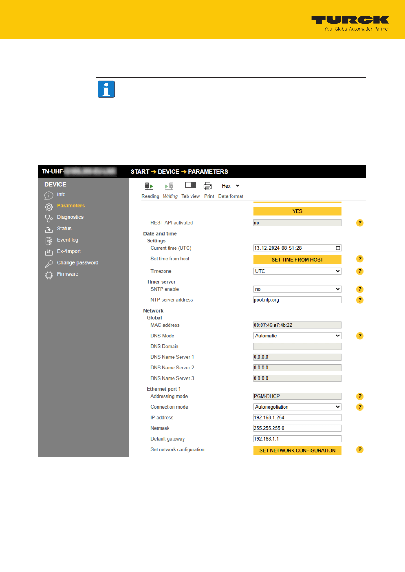
The device must be in PGM mode in order to set the IP address via the web server.
Open the web server.
Log into the device as administrator.
Click Parameters Ò Network.
Change the IP address and, if necessary, also the subnet mask and default gateway.
Write the new IP address, subnet mask and default gateway via SET NETWORK CONFIG-
URATION to the device.
Fig.31: Adjusting network settings via the web server

Commissioning
Connecting the device to a Modbus master with CODESYS
TURCK GmbH | T +49 208 4952-0 | [email protected] | www.turck.com
V02.00 | 2025/09 | 36
7.4 Connecting the device to a Modbus master with CODESYS
Naming convention
TURCK uses the terms "Modbus client" and "Modbus server" according to Modbus Organiza-
tion. The following description uses the terms "Modbus TCP Master" (client) and "Modbus TCP
Slave" (server) only because of the naming in CODESYS.
Hardware used
This example uses the following hardware components:
n UHF reader TN-UHF-Q150-EU-EN (IP address: 192.168.1.61)
Software used
This example uses the following software:
n CODESYS 3.5.8.1 (download free of charge from www.turck.com)
Prerequisites
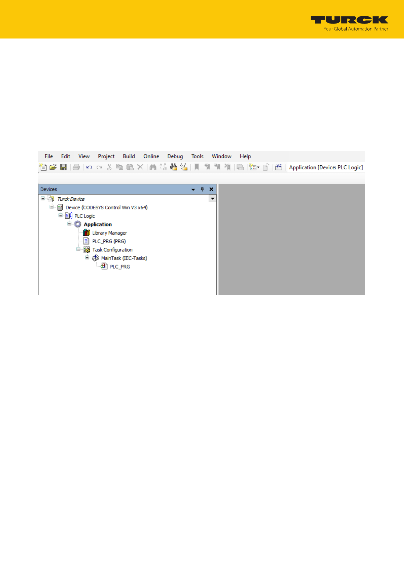
n The software is started.
n A new project has been created.
n The controller has been added to the project.
Commissioning
Connecting the device to a Modbus master with CODESYS
TURCK GmbH | T +49 208 4952-0 | [email protected] | www.turck.com
V02.00 | 2025/09 | 37
7.4.1 Connecting the device with the controller
To connect the device to the controller, the following components must first be added in
CODESYS:
n Ethernet adapter
n Modbus TCP client
n Modbus TCP server
Adding an Ethernet adapter
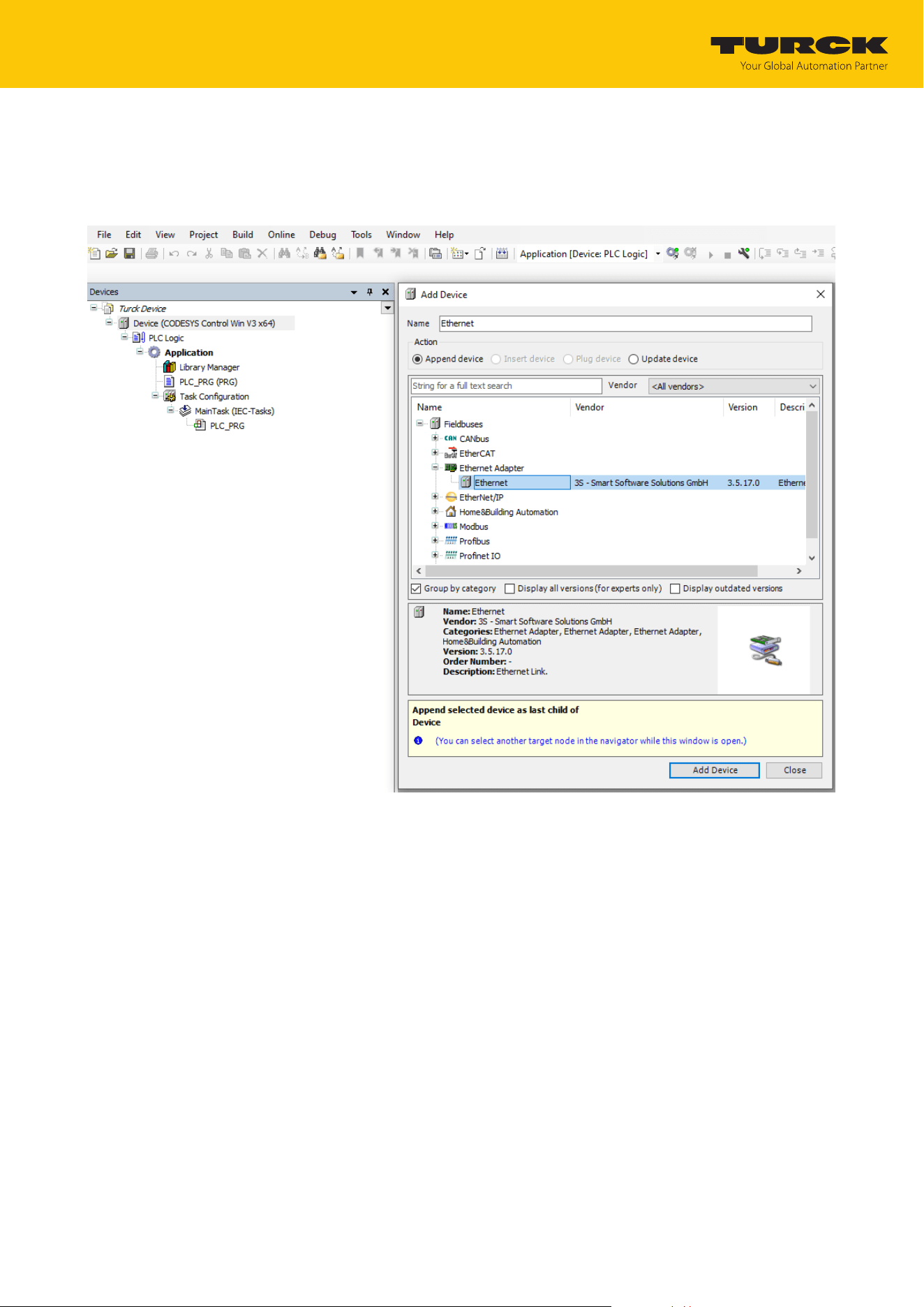
In the project tree, right-click Device (CODESYS Control Win V3).
Fig.32: Project tree
Commissioning
Connecting the device to a Modbus master with CODESYS
TURCK GmbH | T +49 208 4952-0 | [email protected] | www.turck.com
V02.00 | 2025/09 | 38
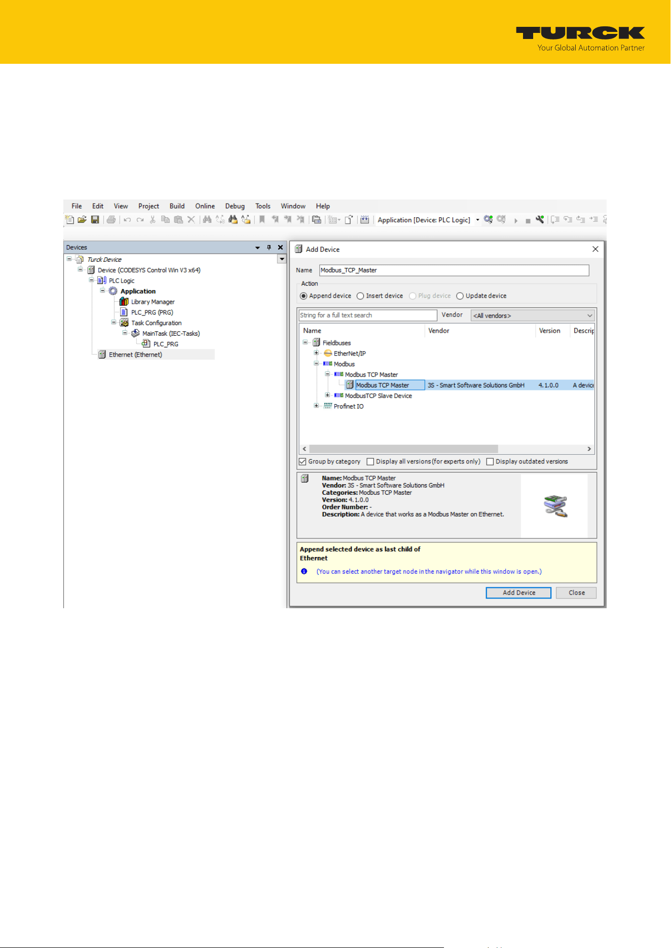
Select Add device.
Select Ethernet adapter.
Click Add device.
a The Ethernet adapter appears as Ethernet (Ethernet) in the project tree.
Fig.33: Adding an Ethernet adapter
Commissioning
Connecting the device to a Modbus master with CODESYS
TURCK GmbH | T +49 208 4952-0 | [email protected] | www.turck.com
V02.00 | 2025/09 | 39
Adding a Modbus client
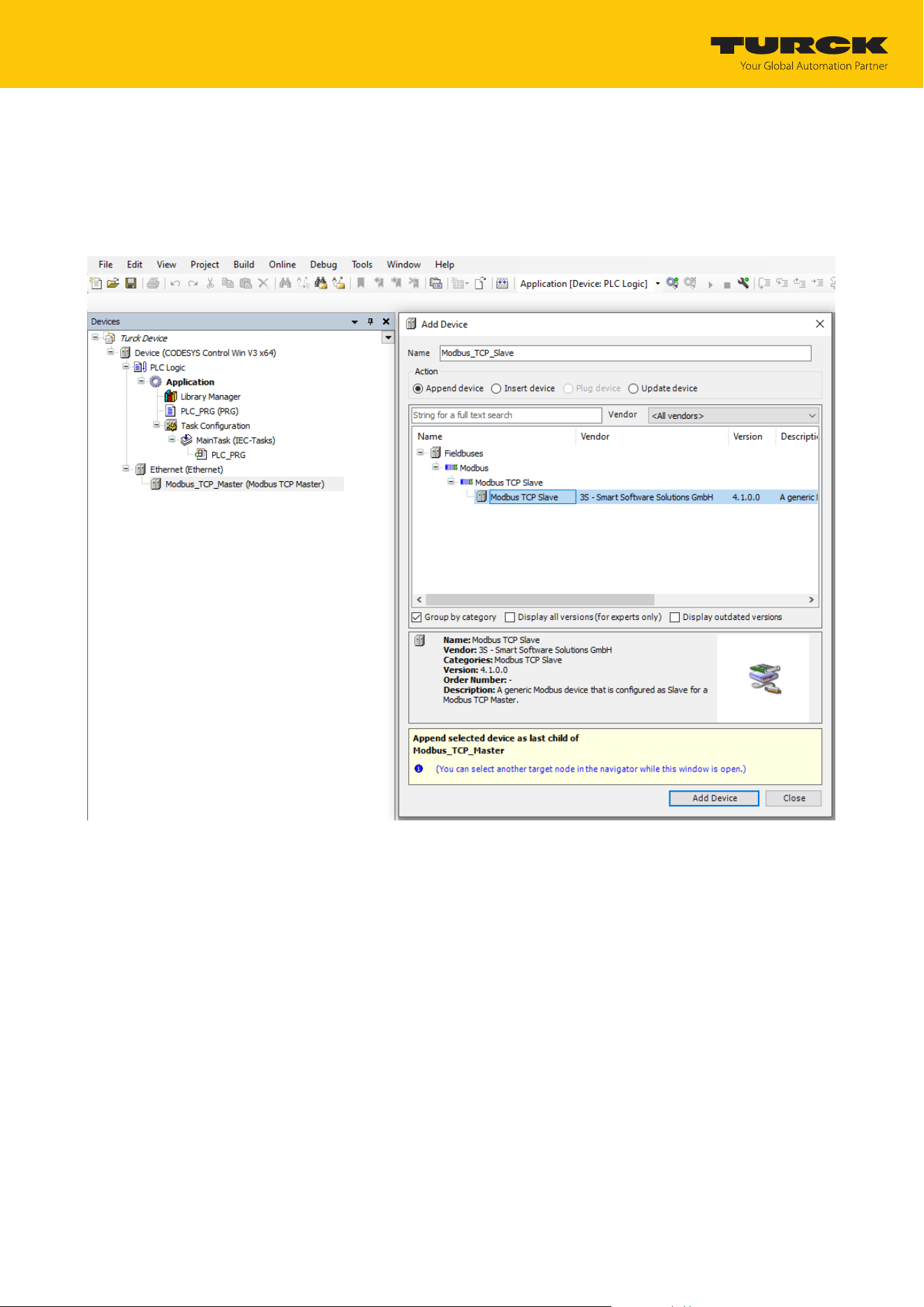
Right-click Ethernet (Ethernet) in the project tree.
Select Add device.
Double-click the Modbus TCP Client.
a The Modbus client appears as Modbus_TCP_Client (Modbus TCP Client) in the project
tree.
Fig.34: Adding a Modbus client
Commissioning
Connecting the device to a Modbus master with CODESYS
TURCK GmbH | T +49 208 4952-0 | [email protected] | www.turck.com
V02.00 | 2025/09 | 40
Adding a Modbus server
Right-click Modbus_TCP_Client (Modbus TCP Client) in the project tree.
Select Add device.
Double-click Modbus TCP server.
a The Modbus server appears as Modbus_TCP_Server in the project tree.
Fig.35: Adding a Modbus server
Commissioning
Connecting the device to a Modbus master with CODESYS
TURCK GmbH | T +49 208 4952-0 | [email protected] | www.turck.com
V02.00 | 2025/09 | 41
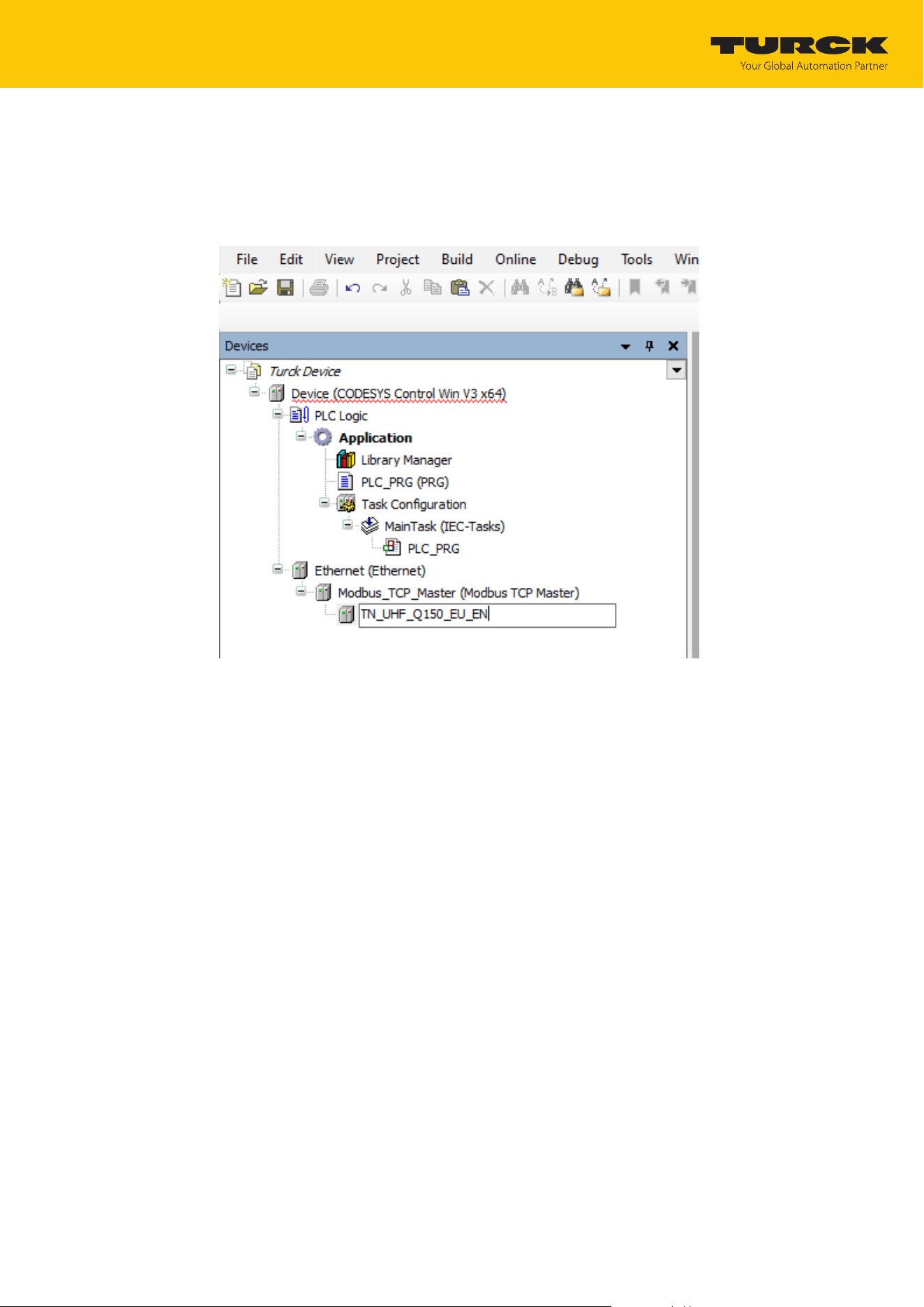
7.4.2 Renaming a Modbus slave
Click Modbus server in the project tree.
Press [F2].
Adjust the name of the server in the project tree of the application.
Fig.36: Assigning a device name (here: TN_UHF_Q150_EU_EN)
Commissioning
Connecting the device to a Modbus master with CODESYS
TURCK GmbH | T +49 208 4952-0 | [email protected] | www.turck.com
V02.00 | 2025/09 | 42
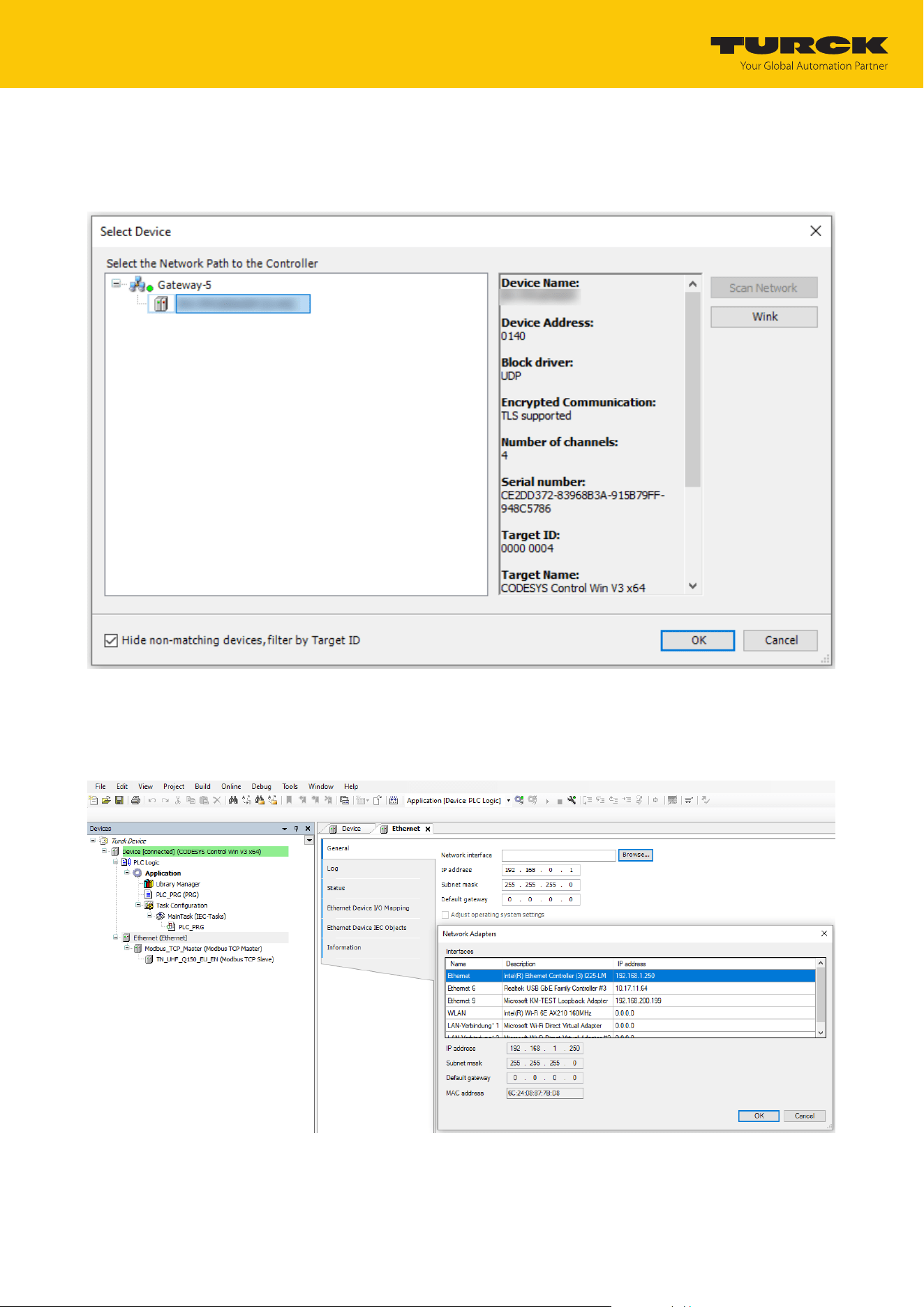
7.4.3 Setting up network interfaces
Click Device Ò Scan network.
Select Modbus client and confirm with OK.
Fig.37: Setting up a network interface to the Modbus client
Double-click Ethernet.
Open the Network Adapter dialog in the General tab via the … button.
Enter the IP address of the Modbus client.
Fig.38: Modbus client – Entering the IP address (here: 192.168.1.60)
Commissioning
Connecting the device to a Modbus master with CODESYS
TURCK GmbH | T +49 208 4952-0 | [email protected] | www.turck.com
V02.00 | 2025/09 | 43
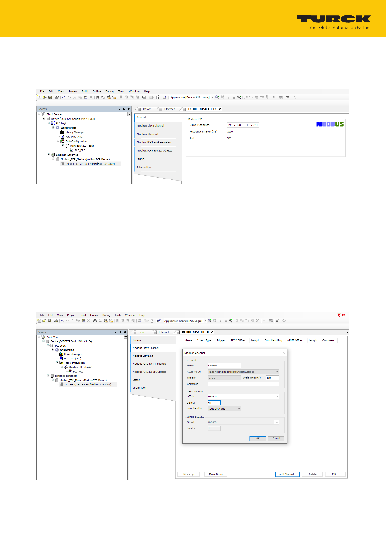
7.4.4 Modbus TCP slave — setting the IP address
Double-click the Modbus TCP server.
In the General tab enter the IP address of the server.
Fig.39: Modbus server – Entering the IP address (here: 192.268.1.61)
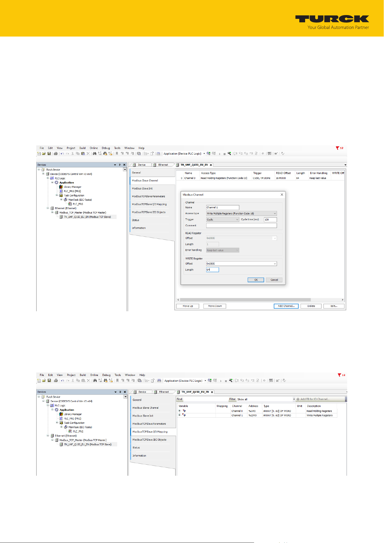
7.4.5 Defining Modbus channels (registers)
Defining channel 0 (input data)
Double-click the Modbus TCP server.
In the Modbus server channel tab Ò select Add channel.
Enter the following values:
n Name of channel
n Access type: Read holding registers
n Offset: 0x0000
n Length: 64 registers (128 bytes)
Confirm with OK.
Fig.40: Defining READ registers
Commissioning
Connecting the device to a Modbus master with CODESYS
TURCK GmbH | T +49 208 4952-0 | [email protected] | www.turck.com
V02.00 | 2025/09 | 44
Defining channel 1 (output data)
Double-click the Modbus TCP server.
In the Modbus server channel tab Ò select Add channel.
Enter the following values:
n Name of channel
n Access type: Write multiple registers
n Offset: 0x0800
n Length: 64 registers (128 bytes)
Confirm with OK.
Fig.41: Setting the WRITE registers
Changing channel addresses
Double-click the Modbus TCP server.
Click the Modbus TCP server I/O image tab.
Enter the address in the corresponding table column.
Fig.42: Changing channel addresses

Commissioning
Connecting the device to a Modbus master with CODESYS
TURCK GmbH | T +49 208 4952-0 | [email protected] | www.turck.com
V02.00 | 2025/09 | 45
7.4.6 Connecting the device online with the controller
Select device.
Click Online Ò Login.
7.4.7 Reading out process data
The process data can be interpreted using mapping if the device is connected online with the
controller.
Double-click the Modbus TCP server.
Click the Modbus TCP server I/O image tab.
a The process data is displayed.
7.4.8 Modbus TCP — mapping
For an overview of Modbus TCP mapping, see the web server.
Click Documentation in the navigation bar at the top of the screen.
Click Modbus TCP Mapping.
a The Modbus TCP mapping of the device is displayed.
Commissioning
Connecting the device to an EtherNet/IP scanner using RSLogix
TURCK GmbH | T +49 208 4952-0 | [email protected] | www.turck.com
V02.00 | 2025/09 | 46
7.5 Connecting the device to an EtherNet/IP scanner using RSLogix
Hardware used
This example uses the following hardware components:
n Rockwell controller CompactLogix L30ER
n UHF reader TN-UHF-Q150-EU-EN
Software used
This example uses the following software:
n Rockwell RSLogix
n EDS file for TN-UHF-Q150-EU-EN (available free of charge as a download at www.turck.com)
Prerequisites
n The software is started.
n A new project has been created.
n The controller has been added to the project.
7.5.1 Installing an EDS file
The EDS file is available free of charge for download from www.turck.com.
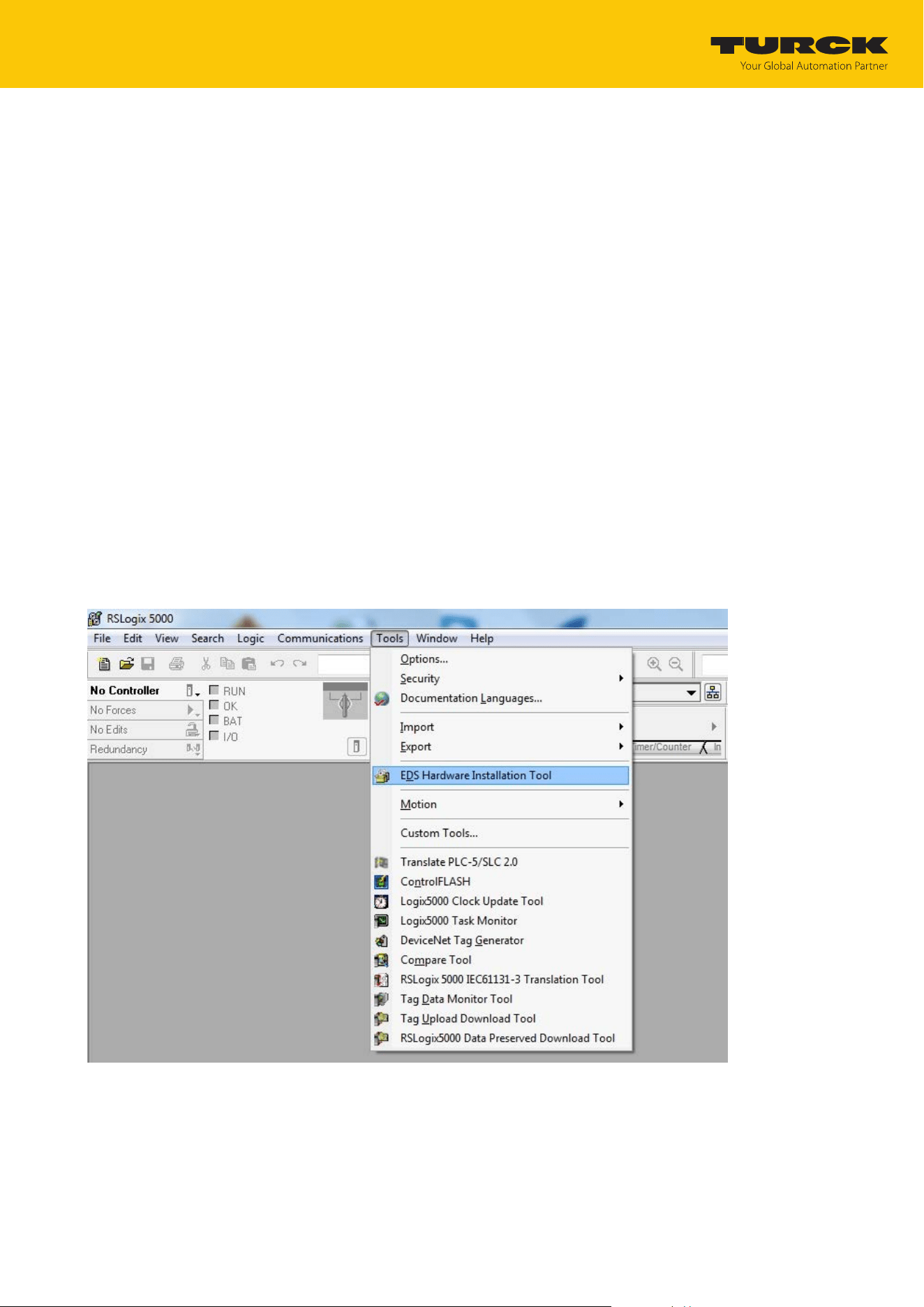
Include an EDS file: Click Tools Ò EDS Hardware Installation Tool.
Fig.43: Opening the EDS Hardware Installation Tool
Commissioning
Connecting the device to an EtherNet/IP scanner using RSLogix
TURCK GmbH | T +49 208 4952-0 | [email protected] | www.turck.com
V02.00 | 2025/09 | 47
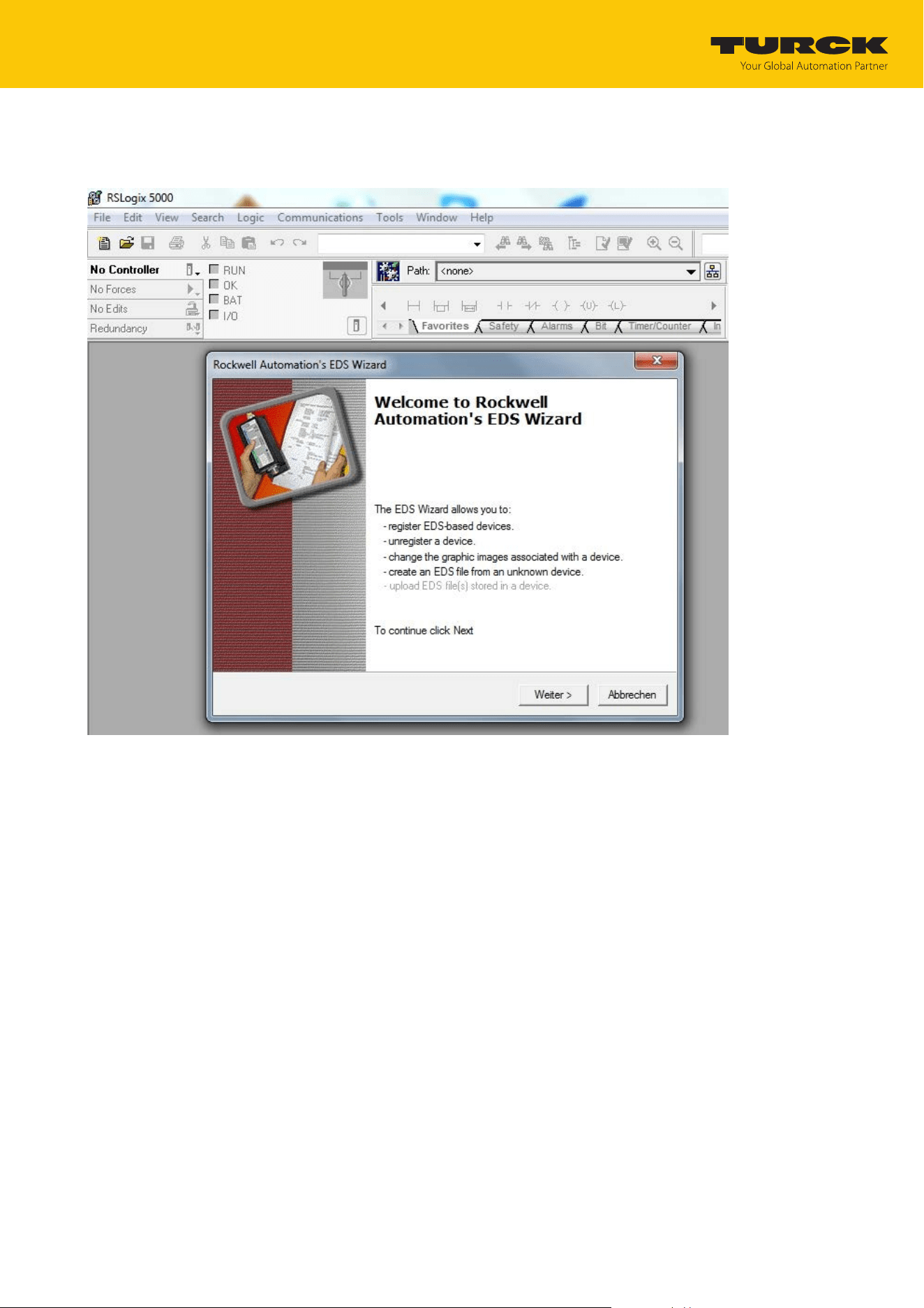
The wizard for the installation of EDS file opens.
Click Next to select the EDS file.
Fig.44: Starting the EDS Wizard
Commissioning
Connecting the device to an EtherNet/IP scanner using RSLogix
TURCK GmbH | T +49 208 4952-0 | [email protected] | www.turck.com
V02.00 | 2025/09 | 48
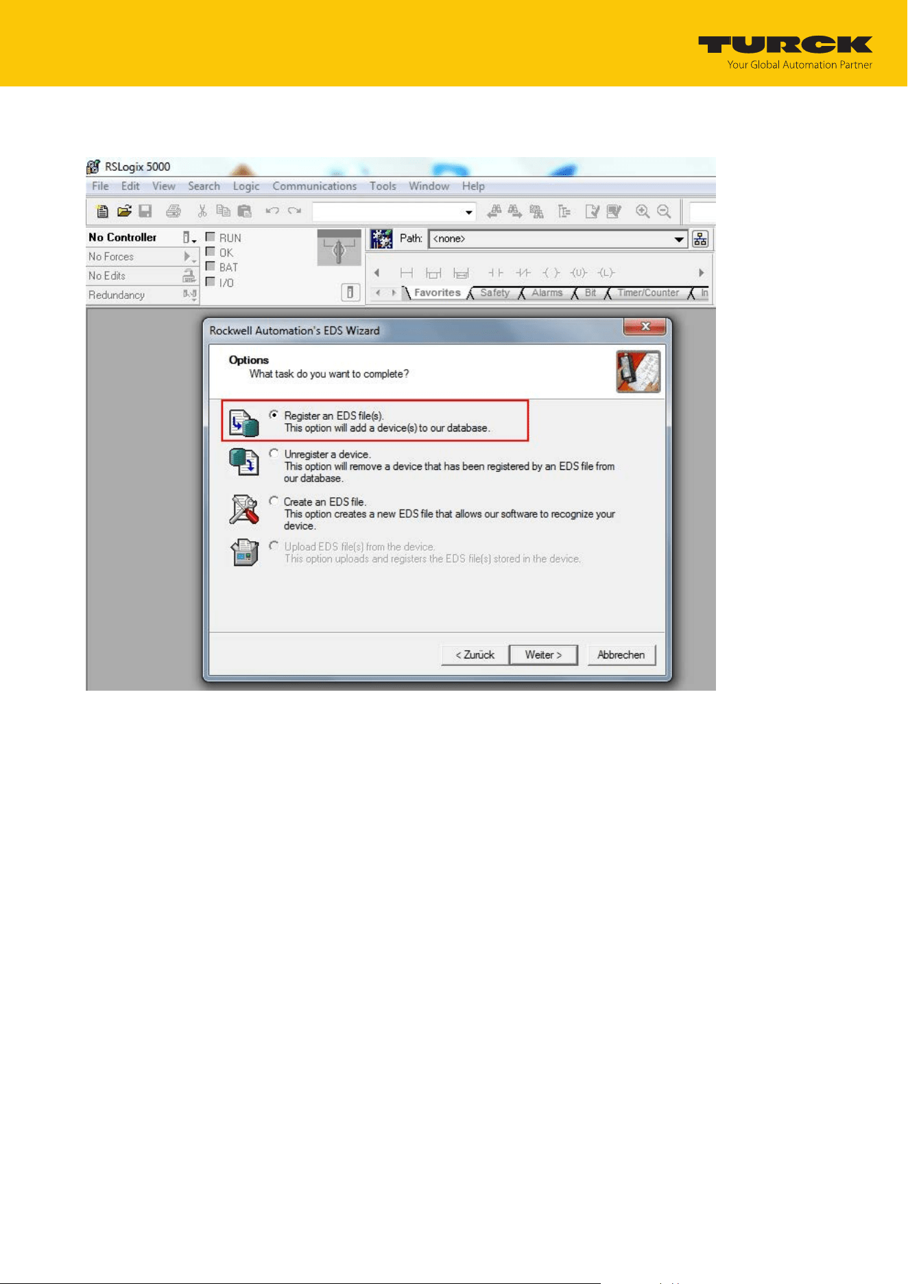
Select the Register an EDS file(s) option and confirm with Next.
Fig.45: Option selection — registering an EDS file(s)
Commissioning
Connecting the device to an EtherNet/IP scanner using RSLogix
TURCK GmbH | T +49 208 4952-0 | [email protected] | www.turck.com
V02.00 | 2025/09 | 49
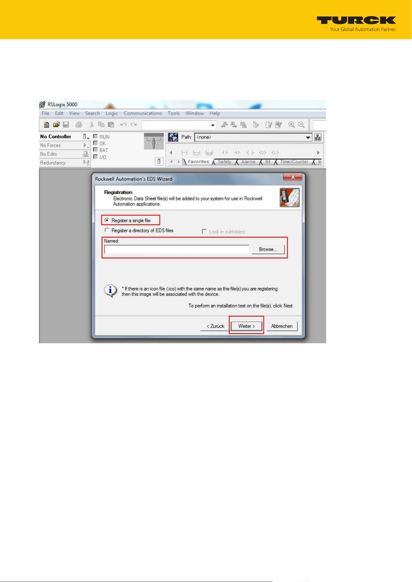
Select EDS file: Select single file or folder (example: single file).
Enter a path for the memory location of the EDS file.
Confirm with Next.
a The installation wizard guides you through the further installation.
Fig.46: Selecting an EDS file
Commissioning
Connecting the device to an EtherNet/IP scanner using RSLogix
TURCK GmbH | T +49 208 4952-0 | [email protected] | www.turck.com
V02.00 | 2025/09 | 50
7.5.2 Connecting the device with the controller
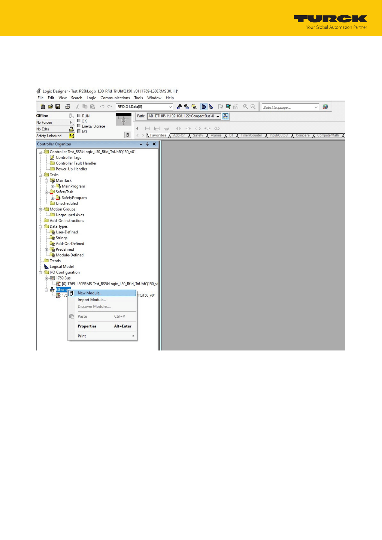
Right-click I/O configuration Ò Ethernet.
Click New module.
Fig.47: Adding a new module
Commissioning
Connecting the device to an EtherNet/IP scanner using RSLogix
TURCK GmbH | T +49 208 4952-0 | [email protected] | www.turck.com
V02.00 | 2025/09 | 51
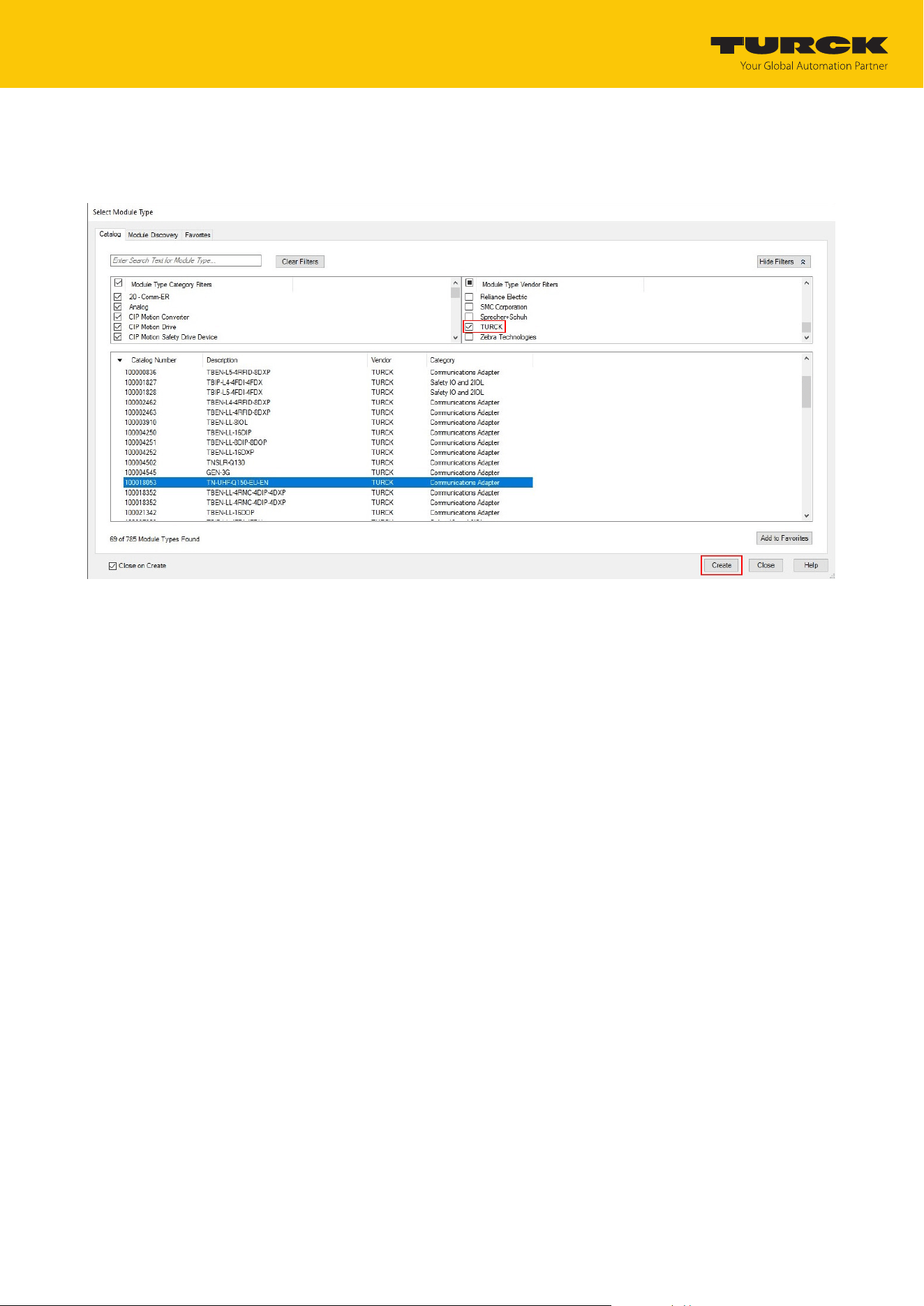
Under Module Type Vendor Filters, select TURCK.
Select the required device.
Confirm the selection with Create.
Fig.48: Selecting an EDS file
Commissioning
Connecting the device to an EtherNet/IP scanner using RSLogix
TURCK GmbH | T +49 208 4952-0 | [email protected] | www.turck.com
V02.00 | 2025/09 | 52
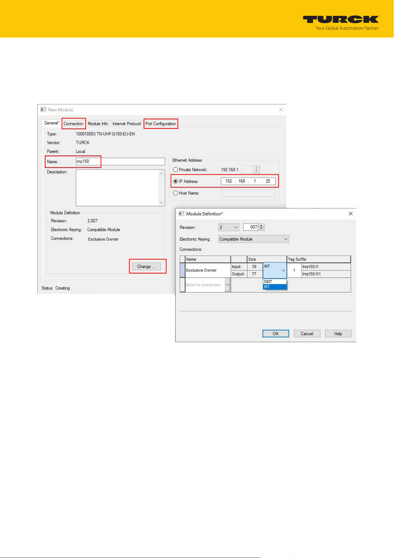
Assign a module name.
Enter the IP address of the device.
Select an integer as a format for the input data and output data: Click Change Ò In the
following window select INT.
Optional: Set the connection and port configuration.
Fig.49: Module settings
Commissioning
Connecting the device to an EtherNet/IP scanner using RSLogix
TURCK GmbH | T +49 208 4952-0 | [email protected] | www.turck.com
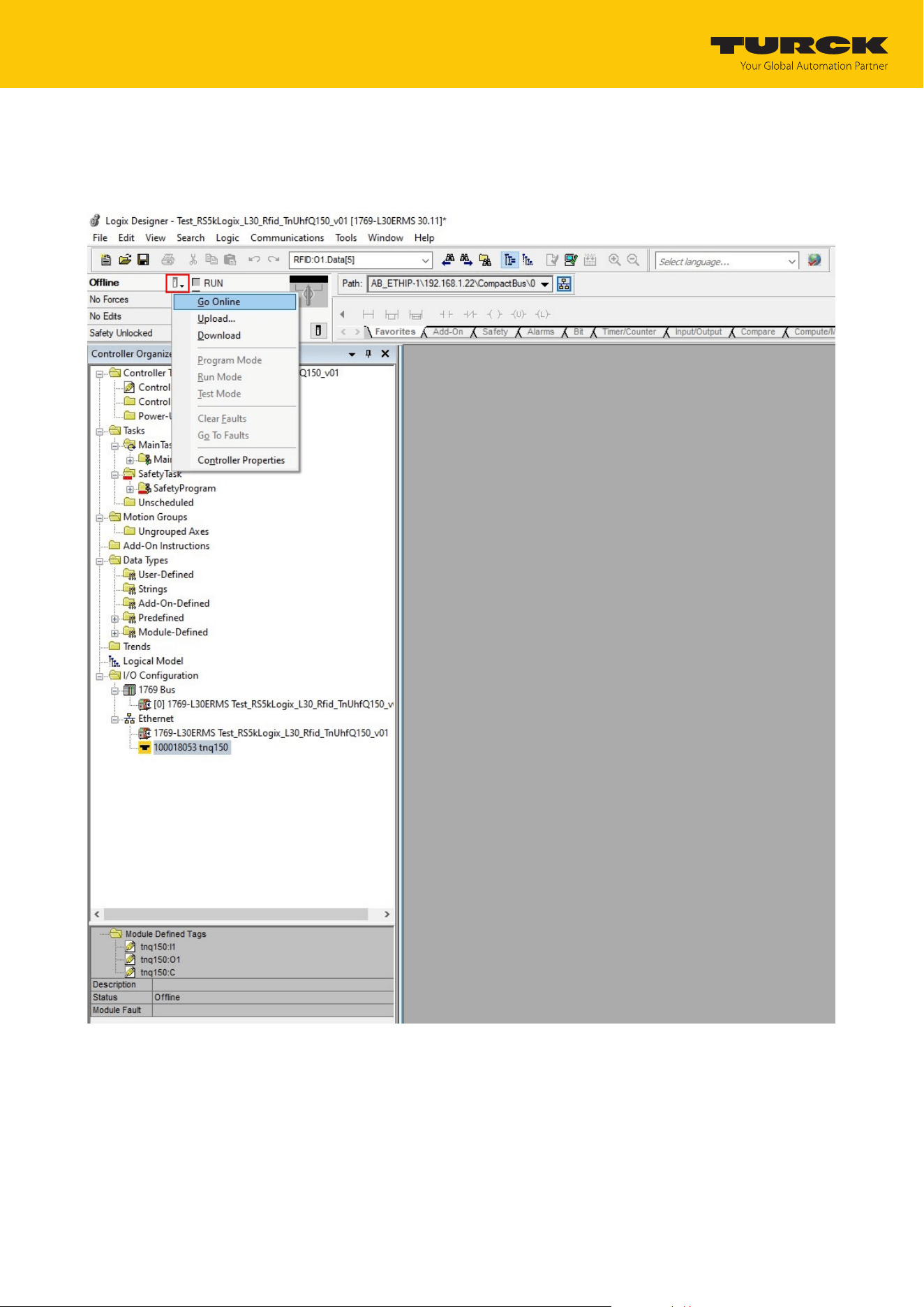
V02.00 | 2025/09 | 53
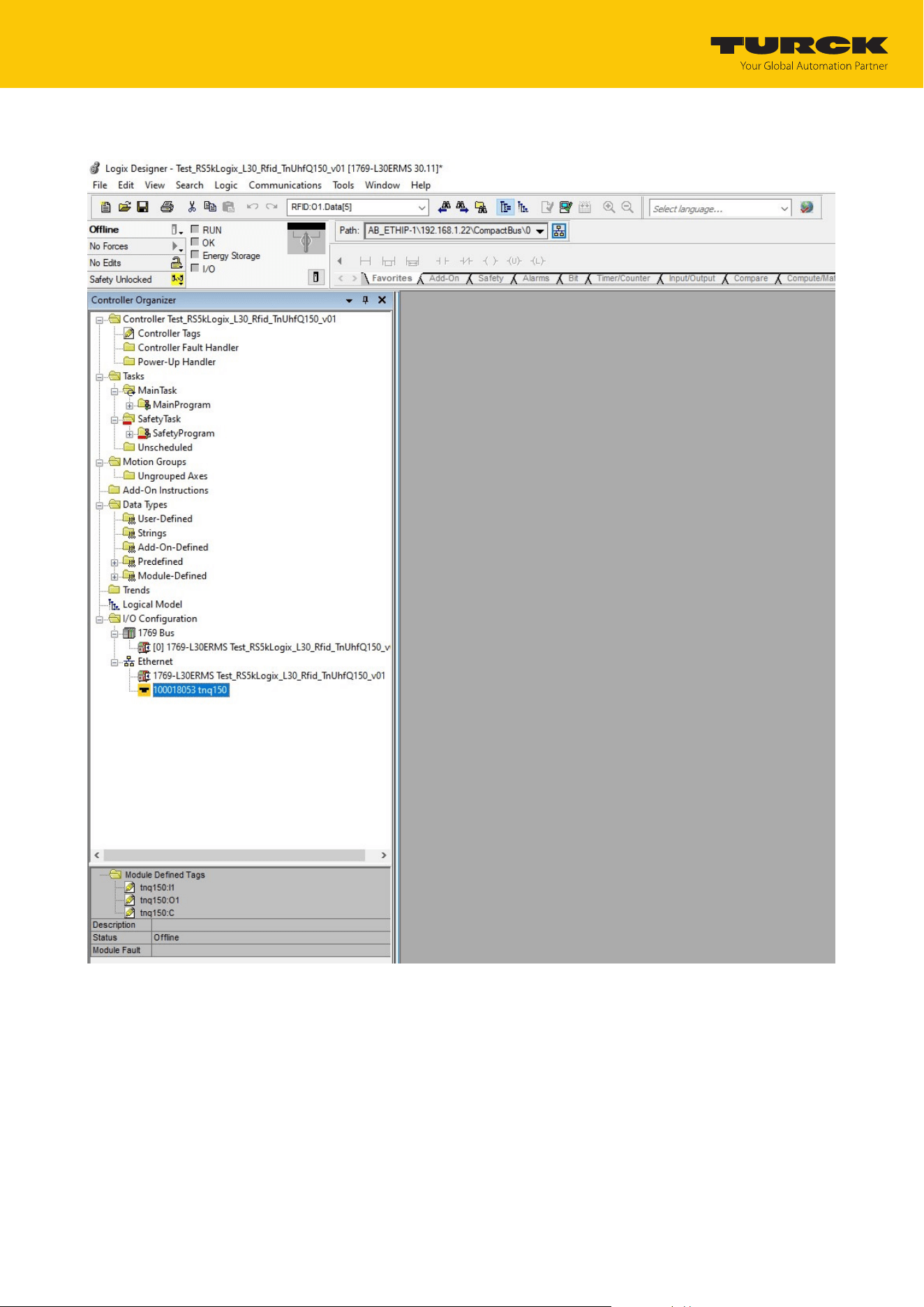
The device appears in the project tree.
Fig.50: Device in the project tree
Commissioning
Connecting the device to an EtherNet/IP scanner using RSLogix
TURCK GmbH | T +49 208 4952-0 | [email protected] | www.turck.com
V02.00 | 2025/09 | 54
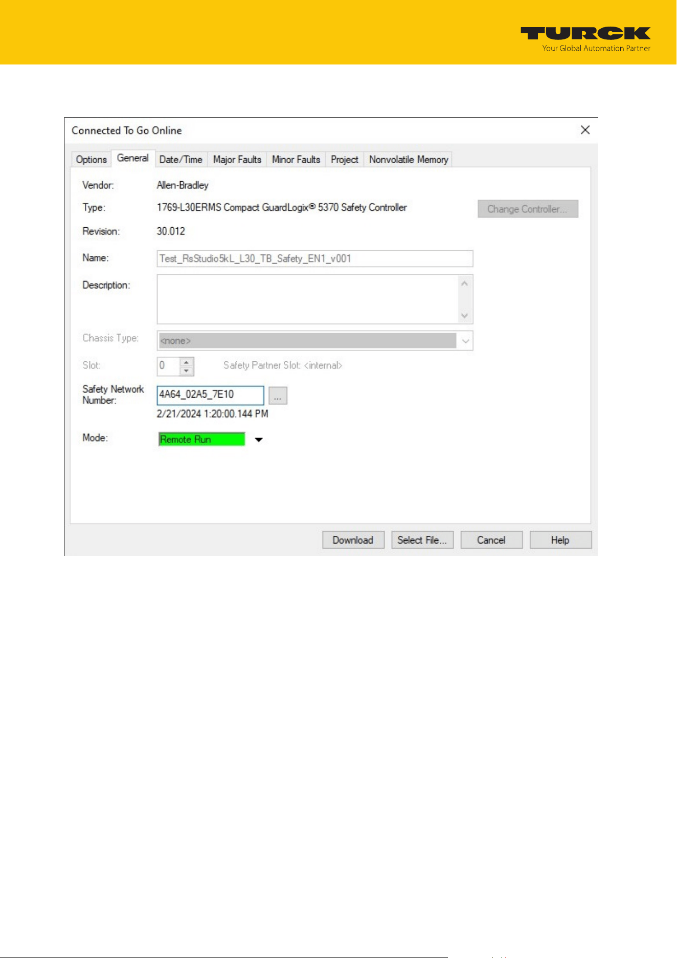
7.5.3 Connecting the device online with the controller
Select the controller.
Click Go online.
Fig.51: Connecting the device online
Commissioning
Connecting the device to an EtherNet/IP scanner using RSLogix
TURCK GmbH | T +49 208 4952-0 | [email protected] | www.turck.com
V02.00 | 2025/09 | 55
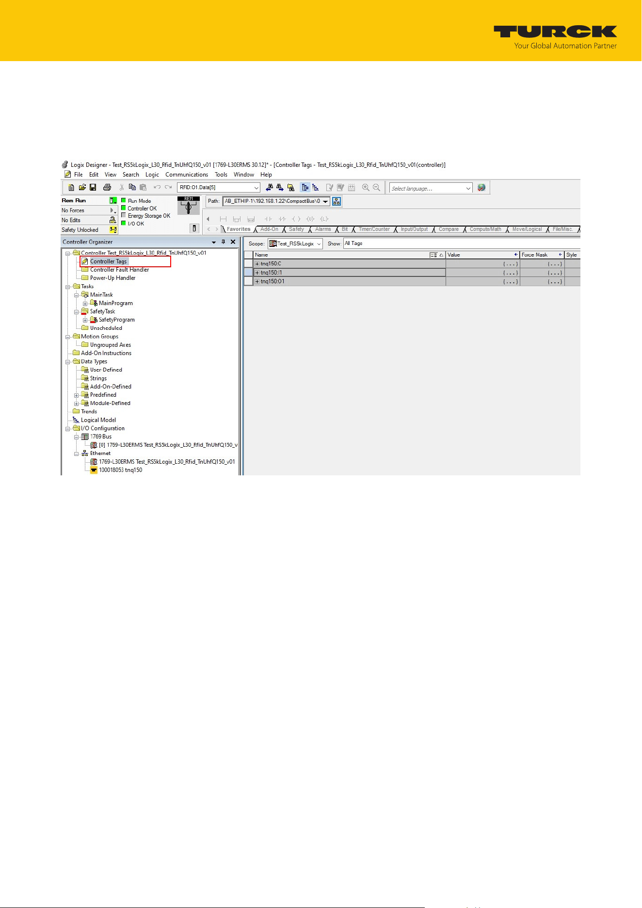
In the following window (Connected To Go Online), click Download.
Fig.52: Click Download
Confirm all the subsequent messages.
Commissioning
Connecting the device to an EtherNet/IP scanner using RSLogix
TURCK GmbH | T +49 208 4952-0 | [email protected] | www.turck.com
V02.00 | 2025/09 | 56
7.5.4 Reading out process data
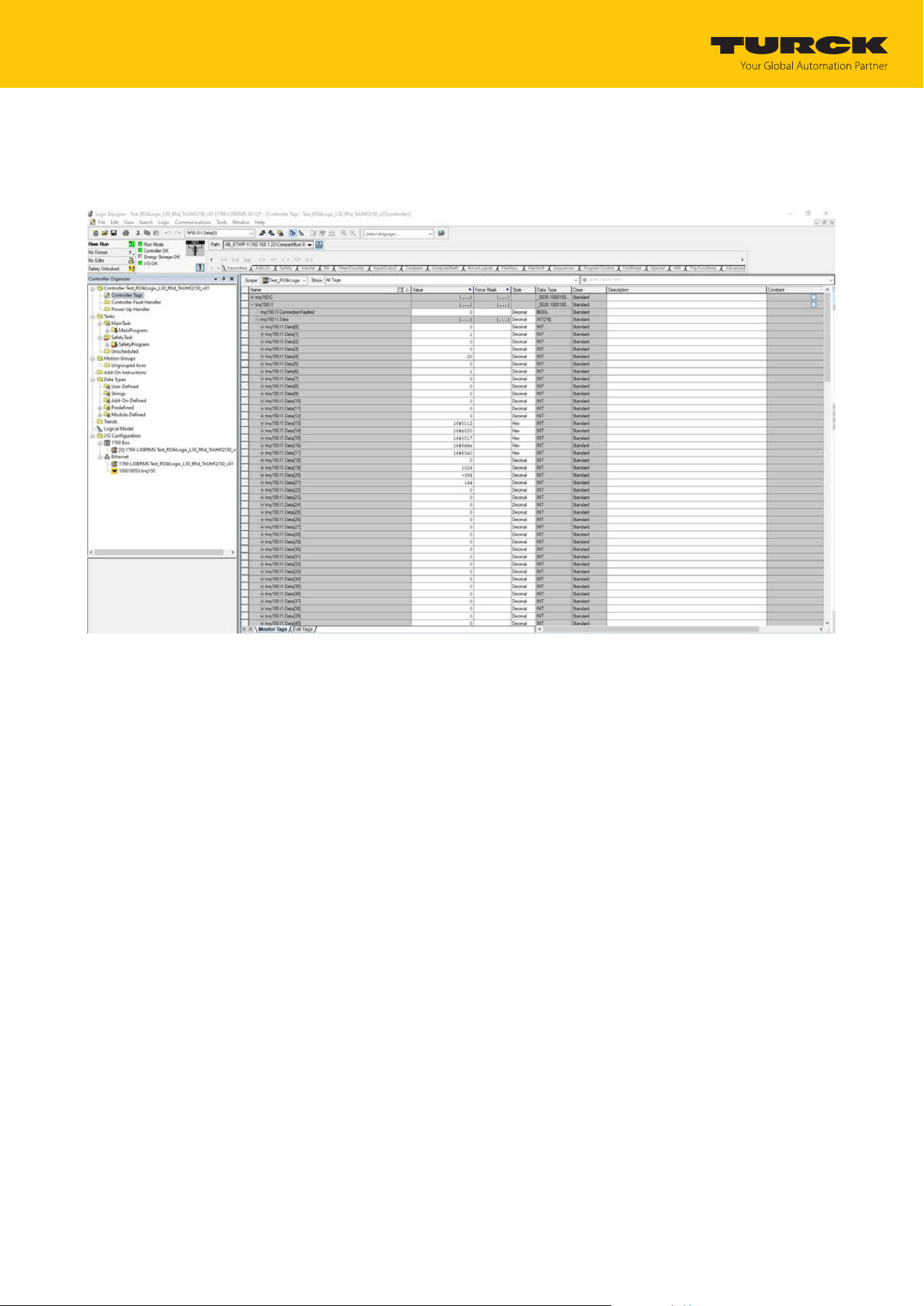
Select Controller tags in the project tree.
a Parameter data (tnq150:C), input data tnq150:I1) and output data (tnq150:O1) can be ac-
cessed.
Fig.53: Access to parameter data, input data and output data
Commissioning
Connecting the device to an EtherNet/IP scanner using RSLogix
TURCK GmbH | T +49 208 4952-0 | [email protected] | www.turck.com
V02.00 | 2025/09 | 57
Example: Process input data — tag in the detection range of the reader
In the following example a tag is located in the detection range of the reader. The process data
can be interpreted using mapping.
Fig.54: Process input data — example

Commissioning
Connecting the device to a PROFINET master using the TIA Portal
TURCK GmbH | T +49 208 4952-0 | [email protected] | www.turck.com
V02.00 | 2025/09 | 58
7.6 Connecting the device to a PROFINET master using the TIA Portal
The following example describes the connection of the device to a Siemens controller in
PROFINET with the SIMATIC STEP7 Professional V16 programming software (TIA Portal).
Hardware used
This example uses the following hardware components:
n Siemens S7-1500 controller
n UHF reader TN-UHF-Q150-EU-EN
Software used
This example uses the following software:
n SIMATIC STEP7 Professional V16 (TIA Portal)
n GSDML file for TN-UHF-Q150-EU-EN (available free of charge as a download at
www.turck.com)
Prerequisites
n The software is started.
n A new project has been created.
n The controller has been added to the project.
Commissioning
Connecting the device to a PROFINET master using the TIA Portal
TURCK GmbH | T +49 208 4952-0 | [email protected] | www.turck.com
V02.00 | 2025/09 | 59
7.6.1 Installing a GSDML file
The GSDML file is available free of charge for download from www.turck.com.
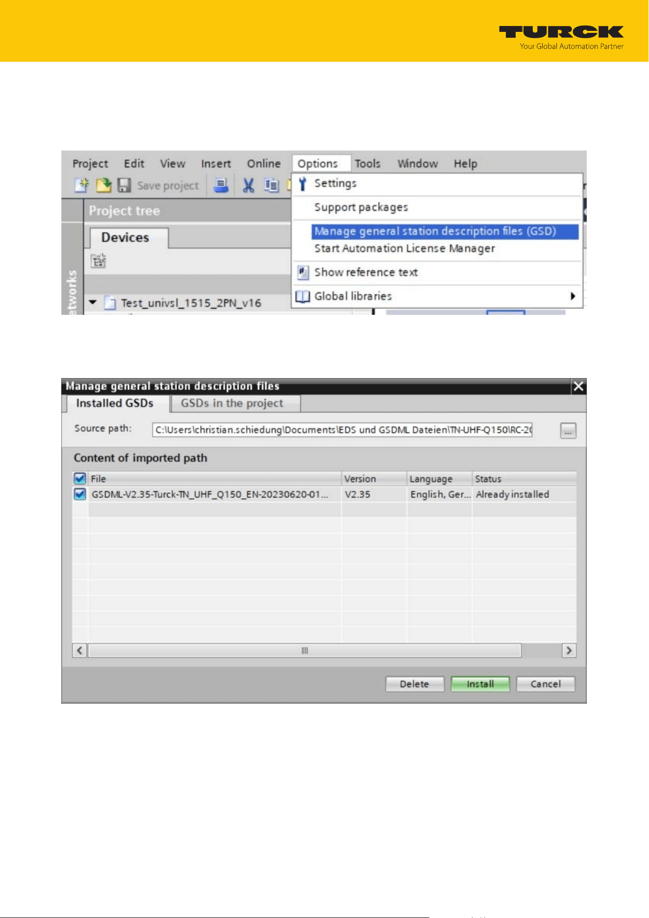
Include a GSDML file: Click Tools Ò Manage device description files (GSD).
Fig.55: Include the GSDML file
Install a GSDML file: Enter the memory location of the GSDML file and click Install.
a The device is entered in the hardware catalog of the programming software.
Fig.56: Installing a GSDML file
Commissioning
Connecting the device to a PROFINET master using the TIA Portal
TURCK GmbH | T +49 208 4952-0 | [email protected] | www.turck.com
V02.00 | 2025/09 | 60
7.6.2 Connecting the device with the controller
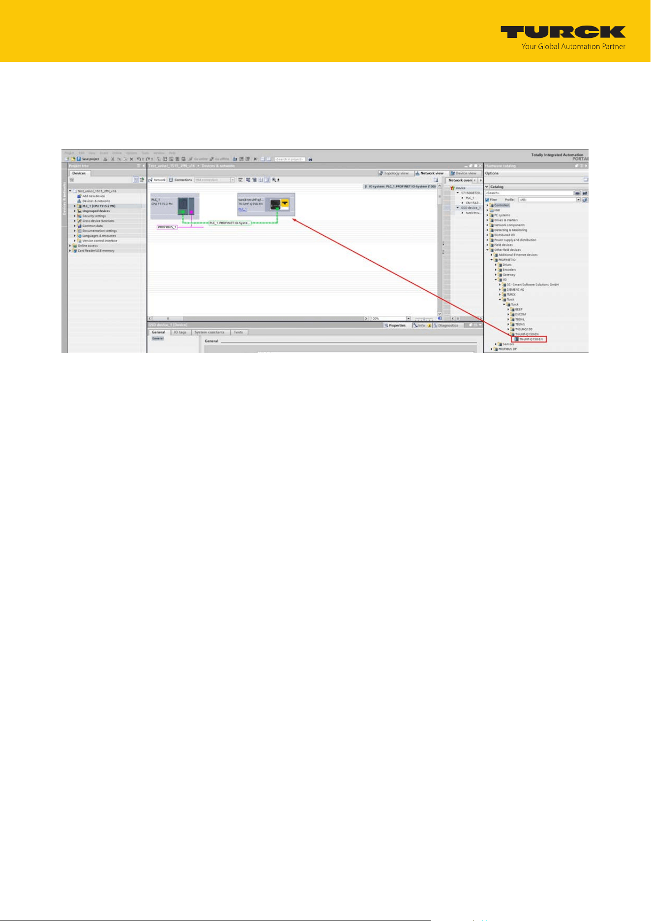
Select the RFID interface from the hardware catalog and drag it to the hardware window.
Connect the device with the controller in the hardware window.
Fig.57: Connecting the device with the controller
Commissioning
Connecting the device to a PROFINET master using the TIA Portal
TURCK GmbH | T +49 208 4952-0 | [email protected] | www.turck.com
V02.00 | 2025/09 | 61
7.6.3 Assigning the PROFINET device name
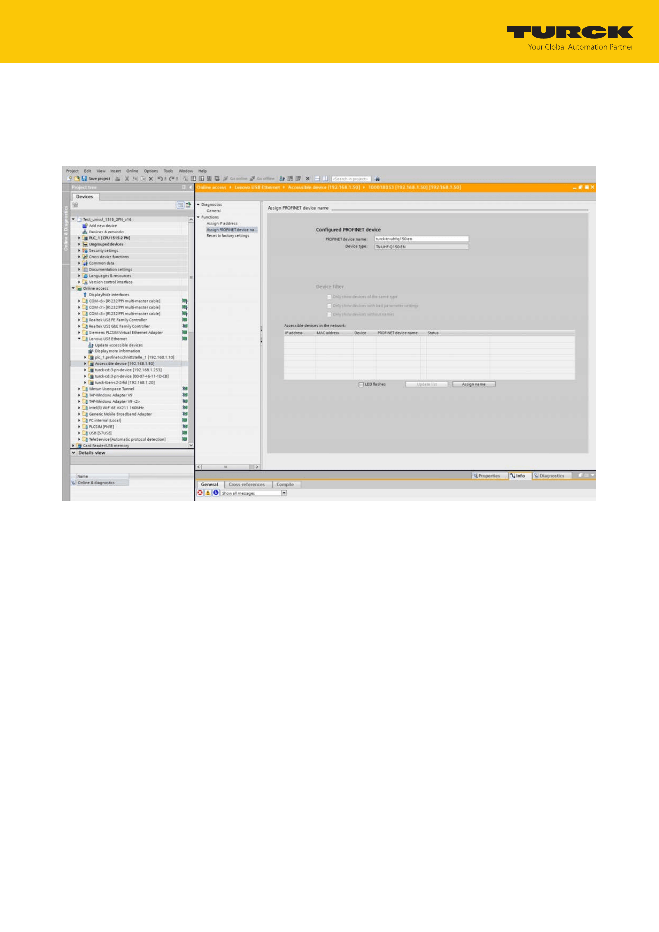
Select Online accesses Ò Online & diagnostics.
Select Functions Ò Assign PROFINET device name.
Assign the required PROFINET device name.
Fig.58: Assigning the PROFINET device name
Commissioning
Connecting the device to a PROFINET master using the TIA Portal
TURCK GmbH | T +49 208 4952-0 | [email protected] | www.turck.com
V02.00 | 2025/09 | 62
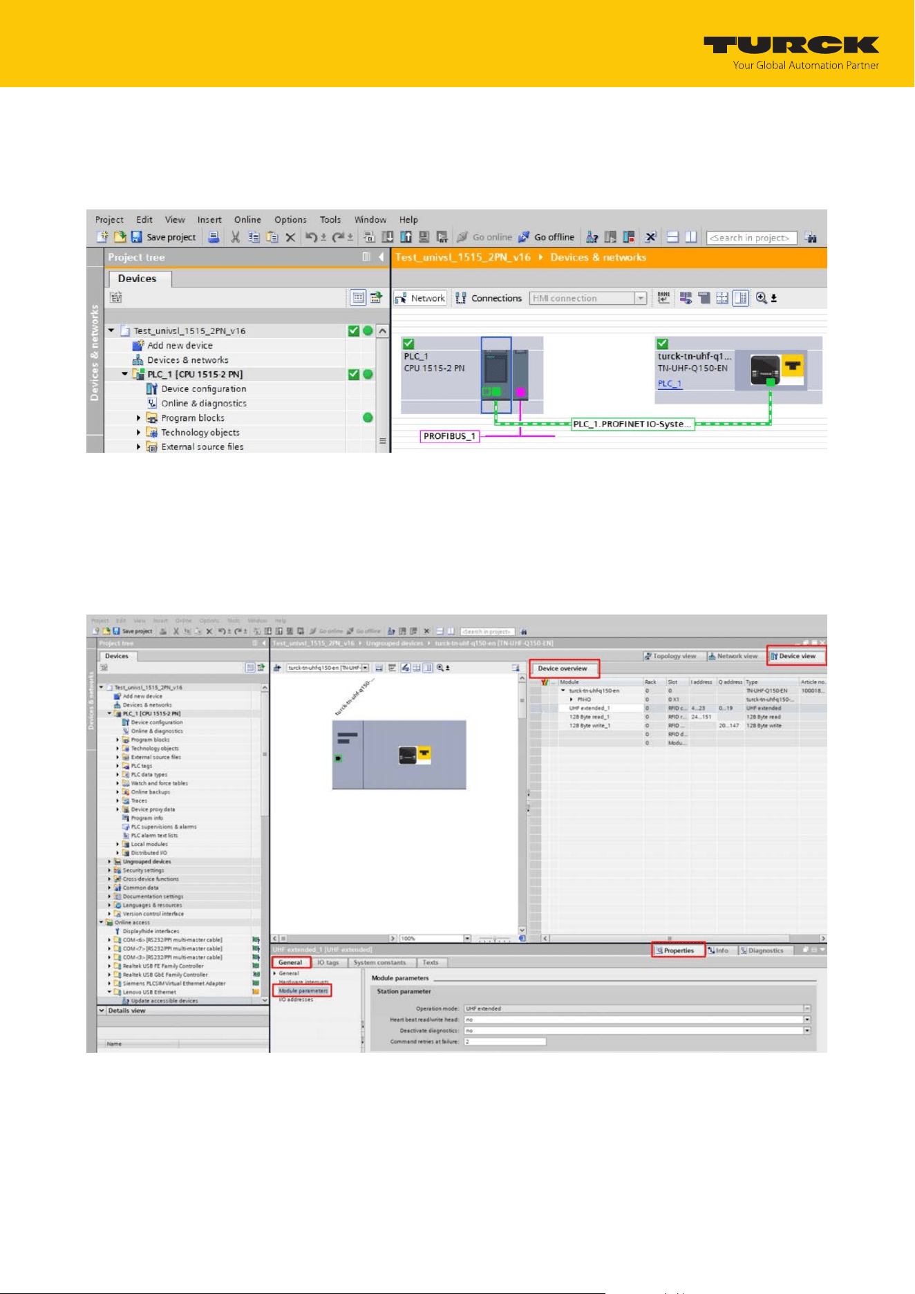
7.6.4 Setting the IP address in the TIA Portal
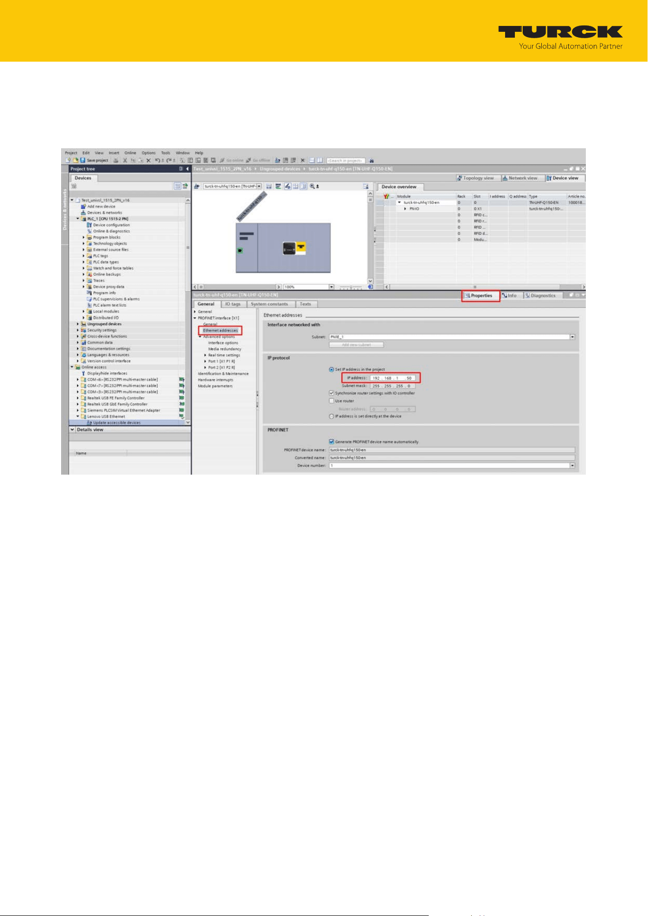
Select Device View Ò Properties tab Ò Ethernet addresses.
Assign the required IP address.
Fig.59: Assigning the IP address
Commissioning
Connecting the device to a PROFINET master using the TIA Portal
TURCK GmbH | T +49 208 4952-0 | [email protected] | www.turck.com
V02.00 | 2025/09 | 63
7.6.5 Connecting the device online with the controller
Start online mode (connect online).
a The device was successfully connected to the controller.
Fig.60: Online mode
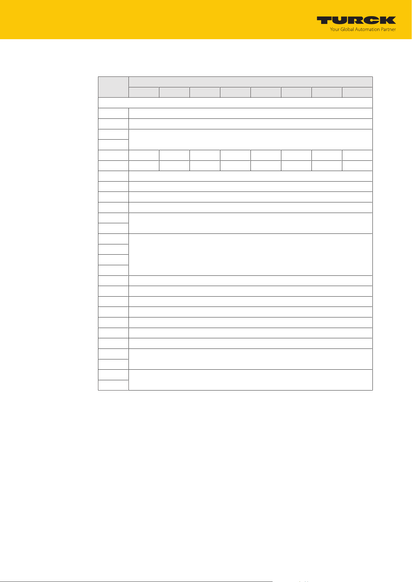
7.6.6 Setting module parameters
Select Device view Ò Device overview.
Select the module to be set.
Click Properties Ò General Ò Module parameters.
Set the station parameters.
Fig.61: Setting module parameters
7.6.7 PROFINET mapping
The PROFINET mapping is the same as the data mapping described in the chapter “Setting”.

Setting
TURCK GmbH | T +49 208 4952-0 | [email protected] | www.turck.com
V02.00 | 2025/09 | 64
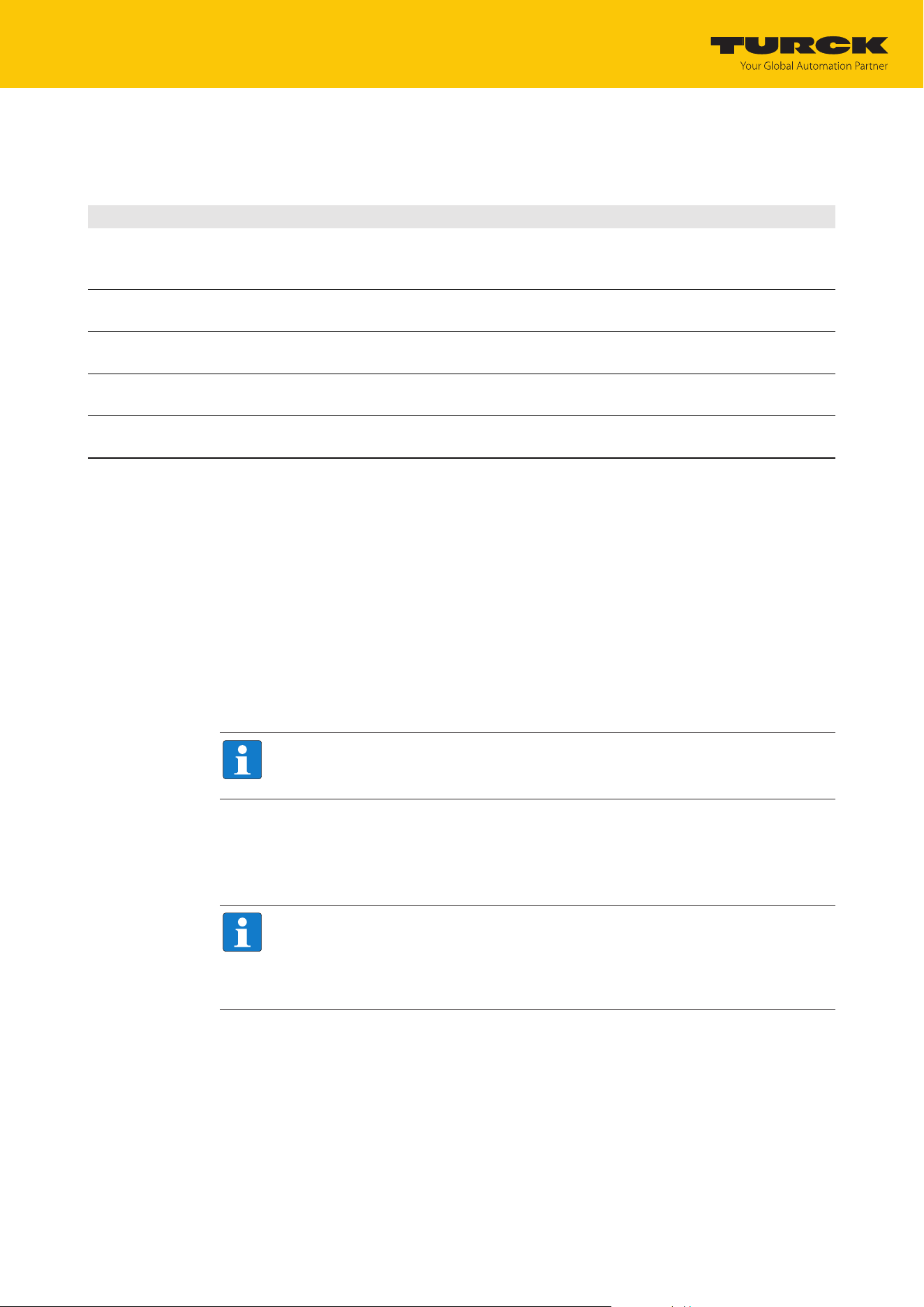
8 Setting
The device can be controlled, read, and set via parameter data, process input data, process out-
put data and diagnostic data. The following table shows the data mapping:
Slot Channel Parameter data Process input data Process output data Diagnostic data
Bytes Meaning Bytes Meaning Bytes Meaning
0 GW 0…1 GW
parameters
0…1 GW
diagnostics
1 0 0…31 RFID
parameters
0…23 RFID input
data
0…23 RFID output
data
0…36 RFID
diagnostics
2 32…33 Length of
read data
24…151 Read data
3 34…35 Length of
write data
24…151 Write data
7 0 152…153 Diagnostics
RFID chan-
nel 0
14 Module
status
154…155 Module
status
Setting
RFID channels — parameter data
TURCK GmbH | T +49 208 4952-0 | [email protected] | www.turck.com
V02.00 | 2025/09 | 65
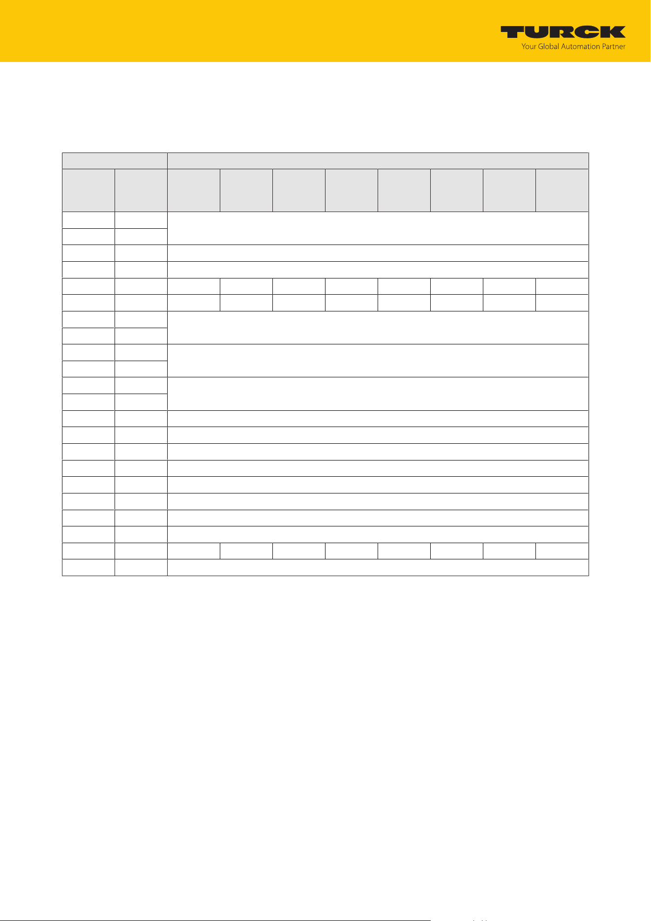
8.1 RFID channels — parameter data
Byte no. Bit
7 6 5 4 3 2 1 0
Channel 0
0 Operating mode (OMRFID)
1 Reserved
2 Reserved
3
4
5 DDI
6 Reserved
7 Reserved
8 Command repetitions (CRET)
9 Reserved
10 Reserved
11
12 Reserved
13
14
15
16 Reserved
17…26 …
27 Reserved
28 Reserved
29 Reserved
30 Reserved
31 Reserved
32 Length of read data (RDS)
33
34 Length of write data (WDS)
35
Setting
RFID channels — parameter data
TURCK GmbH | T +49 208 4952-0 | [email protected] | www.turck.com
V02.00 | 2025/09 | 66
8.1.1 Meaning of the parameter bits
The default values of the firmware, the DTM and the EDS file are shown in bold. The default val-
ues for PROFINET may vary.
Designation Meaning
Operating mode (OMRFID) 0: Deactivated
1: UHF compact
2: UHF Advanced
Deactivate diagnostics (DDI)
0: No (all diagnostic messages on)
1: Yes (diagnostic messages off)
Command repetitions in the
event of a fault (CRET)
Number of command repetitions after a fault signal, default setting: 2
Length of read data (RDS) Size of the read data, default setting depends on the selected interface and field-
bus
Length of write data (WDS) Size of the write data, default setting depends on the selected interface and field-
bus
8.1.2 UHF applications — setting Continuous Presence Sensing Mode
Set adaptions to the presence sensing behavior in the DTM.
Optional: Set the grouping of the EPCs via the Start address parameter:
0: Grouping inactive
1: Grouping active (same EPC is not detected, only the counter in the header is incremen-
ted)
Execute the Continuous Presence Sensing Mode command.
a The UHF-Reader head is switched to Presence Sensing Mode and sends all received data
to the interface as soon as at least one tag is present in the detection range.
a The data received by the UHF reader is stored in the FIFO memory of the interface.
Send the Idle command (0x0000) to then read data from the buffer of the interface.
NOTE
The Continuous Presence Sensing Mode command also stays active after the idle
command is sent.
To pass on data from the FIFO memory of the interface to the controller, execute the
Read buffer (Cont. mode) command (0x0011). The length of the data must be less than
or equal to the value of the available data bytes (BYFI). Depending on the length of the
data, the data is no longer used for grouping.
NOTE
With active grouping: Do not read data from the buffer until the number of available
bytes is stable. If stable data has been collected, the command can be ended by a re-
set as the grouping is no longer based on the collected data, meaning that old EPCs
are detected again.
Do not perform a reset until the data has been read successfully from the buffer.
To stop Continuous Presence Sensing Mode and clear the FIFO memory of the interface,
send the Reset command (0x0800).

Setting
RFID channels — parameter data
TURCK GmbH | T +49 208 4952-0 | [email protected] | www.turck.com
V02.00 | 2025/09 | 67
8.1.3 UHF applications — transferring reader settings
The backup function enables the settings of a UHF reader to be transferred, e.g. when a device
is replaced.
Execute the Backup settings UHF read/write head command.
a The settings of the UHF reader are stored in the interface.
Replace the UHF reader.
Execute the Restore settings UHF read/write head command.
a The data stored in the interface is transferred to the UHF reader.
Setting
RFID channels — process input data
TURCK GmbH | T +49 208 4952-0 | [email protected] | www.turck.com
V02.00 | 2025/09 | 68
8.2 RFID channels — process input data
Process input data — UHF compact operating mode
Byte no. Bit
PROFINET Modbus
EtherNet/
IP
7 6 5 4 3 2 1 0
n + 0 0 Response code (RESC) incl. ERROR and BUSY
n + 1 1
n + 2 2 Loop counter for rapid processing (RCNT)
n + 3 3 Reserved
n + 4 4 TRE1 PNS1 TP
n + 5 5 CMON
n + 6 6 Length (LEN)
n + 7 7
n + 8 8 Error code (ERRC)
n + 9 9
n + 10 10 Tag counter (TCNT)
n + 11 11
n + 12 24 Read data byte 0
n + 13 25 Read data byte 1
n + 14 26 Read data byte 2
n + 15 27 Read data byte 3
n + 16 28 Read data byte 4
n + 17 29 Read data byte 5
n + 18 30 Read data byte 6
n + 19 31 Read data byte 7
… … …
n + 139 151 Read data byte 127
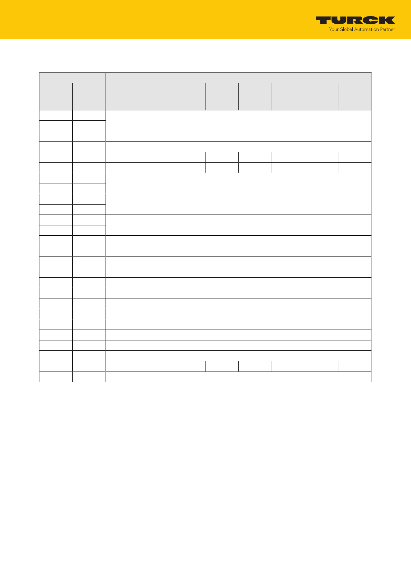
Setting
RFID channels — process input data
TURCK GmbH | T +49 208 4952-0 | [email protected] | www.turck.com
V02.00 | 2025/09 | 69
Process input data — UHF extended operating mode
Byte no. Bit
PROFINET Modbus
EtherNet/
IP
7 6 5 4 3 2 1 0
n + 0 0 Response code (RESC) incl. ERROR and BUSY
n + 1 1
n + 2 2 Loop counter for rapid processing (RCNT)
n + 3 3 Reserved
n + 4 4 TRE1 PNS1 TP
n + 5 5 CMON
n + 6 6 Length (LEN)
n + 7 7
n + 8 8 Error code (ERRC)
n + 9 9
n + 10 10 Tag counter (TCNT)
n + 11 11
n + 12 12 Data (bytes) available (BYFI)
n + 13 13
n + 14 14 Read fragment no. (RFN)
n + 15 15 Write fragment no. (WFN)
n + 16 24 Read data byte 0
n + 17 25 Read data byte 1
n + 18 26 Read data byte 2
n + 19 27 Read data byte 3
n + 20 28 Read data byte 4
n + 21 29 Read data byte 5
n + 22 30 Read data byte 6
n + 23 31 Read data byte 7
… … …
n + 143 151 Read data byte 127

Setting
RFID channels — process input data
TURCK GmbH | T +49 208 4952-0 | [email protected] | www.turck.com
V02.00 | 2025/09 | 70
8.2.1 Meaning of the status bits
Designation Meaning
Response code (RESC) Display of the last command executed
Contains in bit 14: ERROR
n 0: No (the last command was executed successfully.)
n 1: Yes (an error occurred during command execution.)
Contains in bit 15: BUSY
n 0: No (execution of a command completed)
n 1: Yes (command active but not yet completed; system is waiting for execu-
tion, e.g. on tag within the detection range)
Loop counter for rapid
processing (RCNT)
Output of the loop counter for the selected command code
Error reported by read/write
head (TRE1)
0: No (no error)
1: Yes (fault signal of the read/write head)
Parameter not supported by
read/write head (PNS1)
0: No (no error)
1: Yes (parameter not supported by read/write head) (HF bus mode: Parameter
not supported by at least one read/write head)
Tag in the detection range of
read/write head (TP)
0: No (no tag in the detection range of the read/write head)
1: Yes (tag in the detection range of the read/write head)
Continuous (presence sensing)
mode active (CMON)
0: No (continuous mode not active)
1: Yes (continuous mode active)
Length (LEN) Display of the length of the read data
Error code (ERRC) Display of the specific error code if the error bit (ERROR) is set
Tag counter (TCNT) Display of the detected tags. Here, the rising edges of the tags that are read by
an inventory command are counted. A tag that moves along the read/write head
is not counted again if it only leaves the detection range momentarily and re-
enters it (within the set bypass time). If a tag continuously remains within the de-
tection range, it is also only counted once. Exceptions: Continuous Mode with
start address = 3 is active.
The tag counter is reset by the following commands:
n Inventory
n Continuous Mode
n Continuous presence sensing mode
n Reset
Data (bytes) available (BYFI)
(only available with UHF exten-
ded)
Shows the number of bytes in the FIFO memory of the interface.
Ascending: new data read by a tag or received by the device
Descending: command execution completed
Fault signal 0xFFFF: memory overfilled, risk of loss of new data
Read fragment no. (RFN)
(only available with UHF exten-
ded)
If the data to be read exceeds the size of the read data memory, the data is split
into max. 256 fragments. The fragments are numbered consecutively from 1 to
255. From fragment number 256, numbering begins again at 1. The sending of a
fragment is confirmed by the device if the read fragment no. appears in the pro-
cess input data. After the confirmation, the next fragment is read.
0: No fragmentation
In idle mode, the size of the fragments is specified. When a read command is is-
sued, the current fragment number of the read data is indicated.

Setting
RFID channels — process input data
TURCK GmbH | T +49 208 4952-0 | [email protected] | www.turck.com
V02.00 | 2025/09 | 71
Designation Meaning
Write fragment no. (WFN)
(only available with UHF exten-
ded)
If the data that is to be written exceeds the size of the write data memory, the
data is split into max. 256 fragments. The fragments are numbered consecutively
from 1 to 255. From fragment number 256, numbering begins again at 1.
The sending of a fragment is confirmed by the device if the write fragment no.
appears in the process input data. Following confirmation, the next fragment is
written.
0: No fragmentation
In idle mode, the size of the fragments is specified. When a write command is is-
sued, the current fragment number of the written data is indicated.
Read data User-defined read data
8.2.2 Tag in detection range (TP) — using bit or pre-loading the command
The Tag in detection range bit is set automatically if a read/write device detects a tag.
All commands can be sent irrespective of whether the Tag in detection range bit (TP) is set. If
no tag is present in the detection range when the command is sent, the command is executed
by a rising edge at TP. A command is executed immediately if there is a tag in the detection
range at the time of sending.
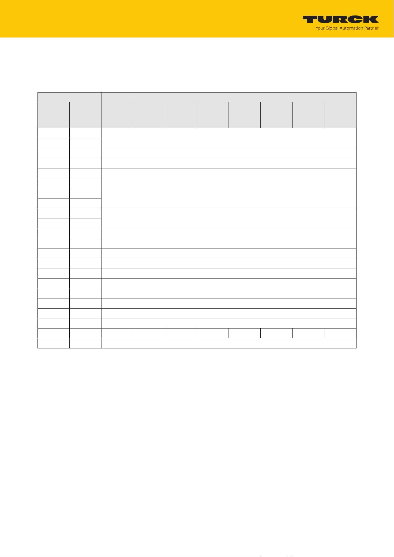
Setting
RFID channels — process output data
TURCK GmbH | T +49 208 4952-0 | [email protected] | www.turck.com
V02.00 | 2025/09 | 72
8.3 RFID channels — process output data
Process output data — UHF compact operating mode
Byte no. Bit
PROFINET Modbus
EtherNet/
IP
7 6 5 4 3 2 1 0
n + 0 0 Command code (CMDC)
n + 1 1
n + 2 2 Loop counter for rapid processing (RCNT)
n + 3 3 Memory area (DOM)
n + 4 4 Start address (ADDR)
n + 5 5
n + 6 6
n + 7 7
n + 8 8 Length (LEN)
n + 9 9
n + 10 10 Length of EPC (SOUID)
n + 11 11 Reserved
n + 12 24 Write data byte 0
n + 13 25 Write data byte 1
n + 14 26 Write data byte 2
n + 15 27 Write data byte 3
n + 16 28 Write data byte 4
n + 17 29 Write data byte 5
n + 18 30 Write data byte 6
n + 19 31 Write data byte 7
… … …
n + 139 151 Write data byte 127
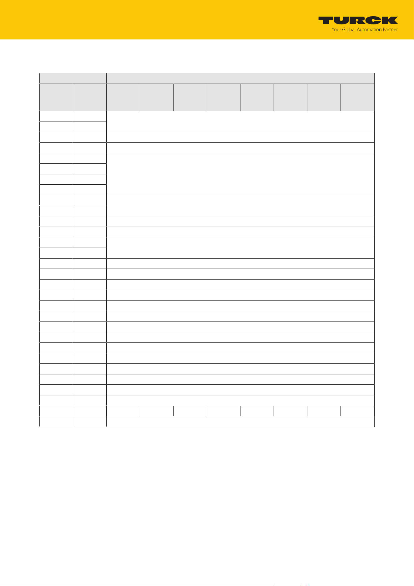
Setting
RFID channels — process output data
TURCK GmbH | T +49 208 4952-0 | [email protected] | www.turck.com
V02.00 | 2025/09 | 73
Process output data — UHF extended operating mode
Byte no. Bit
PROFINET Modbus
EtherNet/
IP
7 6 5 4 3 2 1 0
n + 0 0 Command code (CMDC)
n + 1 1
n + 2 2 Loop counter for rapid processing (RCNT)
n + 3 3 Memory area (DOM)
n + 4 4 Start address (ADDR)
n + 5 5
n + 6 6
n + 7 7
n + 8 8 Length (LEN)
n + 9 9
n + 10 10 Length of EPC (SOUID)
n + 11 11 Reserved
n + 12 12 Timeout (TOUT)
n + 13 13
n + 14 14 Read fragment no. (RFN)
n + 15 15 Write fragment no. (WFN)
n + 16 16 Reserved
n + 17 17 Reserved
n + 18 18 Reserved
n + 19 19 Reserved
n + 20 24 Write data byte 0
n + 21 25 Write data byte 1
n + 22 26 Write data byte 2
n + 23 27 Write data byte 3
n + 24 28 Write data byte 4
n + 25 29 Write data byte 5
n + 26 30 Write data byte 6
n + 27 31 Write data byte 7
… … …
n + 147 151 Write data byte 127

Setting
RFID channels — process output data
TURCK GmbH | T +49 208 4952-0 | [email protected] | www.turck.com
V02.00 | 2025/09 | 74
8.3.1 Meaning of the command bits
Description Meaning
Command code (CMDC) Entry of the command code
Loop counter for rapid pro-
cessing (LCNT)
Loop counter for repeated processing of a command
0: Loop counter off
Memory area (DOM) 0: Kill password
1: EPC
2: TID
3: USER area
4: Access password
5: PC (defines the response length of the EPC)
Start address (ADDR) Specification of the address in bytes from which a command is to be executed in
the memory of the tag. Can be used as an alternative to activating the grouping.
Length (LEN) Entering the length of the data to be read or written
Length of EPC (SOUID) in bytes
Inventory command:
0: The actual length (bytes) of the transferred EPC is transferred with an invent-
ory.
> 0: EPC is output in full.
Other commands (e.g. read or write):
The EPC size should be entered in bytes if a particular tag is to be read, written or
protected. The EPC must be defined in the write data (start byte: 0). The function
of the length of the EPC depends on the command used.
0: No entry of an EPC for executing the command. Only one tag can be located in
the detection range of the read/write device.
> 0: EPC length of the tag that is to be read, written or protected if an EPC is
present in the write data.
Timeout (TOUT) Time in ms in which a command is to be executed. If a command is not executed
within the specified time, the device outputs a fault signal.
0: No timeout, command remains active until the first tag has been read
1: Command is executed once (if there is already a tag in the detection range)
> 1…65535: Time in ms
UHF inventory: Command remains active for the entire specified time
Read fragment no. (RFN) If the data to be read exceeds the size of the read data memory, the data is split
into max. 256 fragments. The fragments are numbered consecutively from 1 to
255. From fragment number 256, numbering begins again at 1. The sending of a
fragment is confirmed by the device if the read fragment no. appears in the pro-
cess input data. After the confirmation, the next fragment is read.
0: No fragmentation
In idle mode, the size of the fragments is specified. When a read command is is-
sued, the fragment no. of the access to the read data of the next fragment is set.
Write fragment no. (WFN) If the data that is to be written exceeds the size of the write data memory, the
data is split into max. 256 fragments. The fragments are numbered consecutively
from 1 to 255. From fragment number 256, numbering begins again at 1.
The sending of a fragment is confirmed by the device if the write fragment no.
appears in the process input data. Following confirmation, the next fragment is
written.
0: No fragmentation
In idle mode, the size of the fragments is specified. When a write command is is-
sued, the fragment no. for the next fragment for the data to be written is set.
Write data User-defined write data or entry of an EPC to select a specific tag for the com-
mand execution (if the "EPC (SOUID) length" command parameter is greater than
0)

Setting
RFID channels — overview of the commands
TURCK GmbH | T +49 208 4952-0 | [email protected] | www.turck.com
V02.00 | 2025/09 | 75
8.4 RFID channels — overview of the commands
RFID commands are initiated via the command code in the process output data of an RFID
channel. The commands can be executed with or without a loop counter function. The loop
counter must be set individually for each new command.
NOTE
After commands are executed without the loop counter function, the device must
be reset to the Idle state before a new command is sent.
After a command is executed, send an idle command to the device.
Command Command code Possible for
hex. dec. UHF
compact
UHF
extended
Idle 0x0000 0 x x
Inventory 0x0001 1 x x
Fast inventory 0x2001 8193 x x
Read 0x0002 2 x x
Fast read 0x2002 8194 x x
Write 0x0004 4 x x
Fast write 0x2004 8196 x x
Write and verify 0x0008 8 x x
Continuous mode 0x0010 16 – x
Get data from buffer
(Continuous mode)
0x0011 17 Max.
128bytes
x
Get data from buffer with fast com-
mand processing
(Continuous mode)
0x2011 8209 Max.
128bytes
x
Continuous presence sensing mode 0x0020 32 – x
End Continuous
(presence sensing) mode
0x0012 18 – x
Read/write head identification 0x0041 65 x x
Direct read/write head command 0x0060 96 x x
Direct read/write head command with
fast command processing
0x2060 8288 x x
Set tag password 0x0102 258 x x
Set tag password with fast command
processing
0x2102 8450 x x
Set read/write head password 0x0100 256 x x
Reset read/write head password 0x0101 257 x x
Set tag protection 0x0103 259 x x
Set tag protection with
fast command processing
0x2103 8451 x x
Set permanent lock (Lock) 0x0105 261 x x
Set permanent lock with fast command
processing
0x2105 8453 x x
Tag info 0x0050 80 x x

Setting
RFID channels — overview of the commands
TURCK GmbH | T +49 208 4952-0 | [email protected] | www.turck.com
V02.00 | 2025/09 | 76
Command Command code Possible for
hex. dec. UHF
compact
UHF
extended
Tag info with fast command
processing
0x2050 8272 x x
Kill UHF tag 0x0200 512 x x
Kill UHF tag with
fast command
processing
0x2200 8704 x x
Restore UHF read/write head
settings
0x1000 4096 x x
Backup settings of the UHF read/write
head
0x1001 4097 x x
Query error/status of UHF read/write
head
0x0042 66 x x
Reset 0x8000 32768 x x

Setting
RFID channels — overview of the commands
TURCK GmbH | T +49 208 4952-0 | [email protected] | www.turck.com
V02.00 | 2025/09 | 77
8.4.1 Command: Idle
The Idle command switches the interface to idle mode. Command execution is canceled. The
EPC is displayed if the reader is configured in Presence Sensing Mode via TAS or the web server.
Overview of output data
For a description of the output data, see [}74]
Request
Loop counter Not required
Command code 0x0000 (hex.), 0 (dec.)
Read/write head address Not required
EPC length Not required
Start address Not required
Length Not required
Command timeout Not required
Write fragment no. Not required
Read fragment no. Not required
Write data Not required
Overview of input data
For a description of the input data, see [}70]
Response
Loop counter See description of the input data
Response code 0x0000 (hex.), 0 (dec.)
Length EPC length of the tag in the detection range
Error code See description of the input data
Tag in
detection range
See description of the input data
Data (bytes) available See description of the input data
Tag counter See description of the input data
Write fragment no. Size of the fragment
Read fragment no. Size of the fragment
Read data, byte 0…n EPC of the tag in the detection range
Setting
RFID channels — overview of the commands
TURCK GmbH | T +49 208 4952-0 | [email protected] | www.turck.com
V02.00 | 2025/09 | 78
8.4.2 Command: Inventory
The Inventory command triggers the reader to search for tags in the detection range and to
read the EPC or, if activated in the UHF reader, the RSSI of the tags. The inventory command can
be executed in single-tag mode and in multi-tag mode.
NOTE
The command code for rapid processing with the loop counter is 0x2001 (hex.) or
8193 (dec.).
Overview of output data
For a description of the output data, see [}74]
Request
Loop counter See description of the output data
Command code 0x0001 (hex.), 1 (dec.)
Read/write head address See description of the output data
EPC length Not required
Start address 1: Grouping of the EPCs active
0: Grouping of the EPCs inactive
Length 0: The actual length (bytes) of the transferred EPC is trans-
ferred with an inventory.
> 0: EPC is output in full.
Command timeout See description of the output data
Write fragment no. 0
Read fragment no. See description of the output data
Write data Not required
Overview of input data
For a description of the input data, see [}70]
Response
Loop counter See description of the input data
Response code 0x0001 (hex.), 1 (dec.)
Length Length of the read data
Error code See description of the input data
Tag in
detection range
See description of the input data
Data (bytes) available See description of the input data
Tag counter Ascending
Write fragment no. 0
Read fragment no. See description of the input data
Read data, byte 0…n See example: UHF read data

Setting
RFID channels — overview of the commands
TURCK GmbH | T +49 208 4952-0 | [email protected] | www.turck.com
V02.00 | 2025/09 | 79
Data format in UHF applications
The UHF read data is formatted by a header. The header has the following structure:
Type Name Meaning
uint8_t Size Data size
uint8_t Block type 1: EPC etc.
other values: reserved
uint8_t Data [size] EPC and read data
The size of EPC/RSSI etc. is dependent on the reader settings.
Reading out the RSSI value
The RSSI value is output in binary code in 2 bytes and corresponds to the two's complement of
the output binary code. Mapped to a signed integer, the 2 bytes output correspond to ten
times the actual RSSI value. Refer to the following table for an example of the RSSI value:
MSB…LSB
(decimal)
MSB…LSB
(binary)
Two’s complement RSSI (dBm)
252 253 11111100 11111101 -771 -77.1
Example: UHF read data (header and EPC, grouping deactivated)
Type Name Meaning
uint8_t Size 14
uint8_t Block type 1
uint8_t Data [14] uint8_t EPC [12]
uint16_t Number of the antenna (LSB Ò MSB)
[2]
Example: UHF read data (header and EPC, grouping activated)
Type Name Meaning
uint8_t Size 16
uint8_t Block type 1
uint8_t Data [16] uint8_t EPC [12]
uint16_t Number of the antenna (LSB Ò MSB)
[2]
uint16_t Number of the read operations (LSB
Ò MSB) [2]

Setting
RFID channels — overview of the commands
TURCK GmbH | T +49 208 4952-0 | [email protected] | www.turck.com
V02.00 | 2025/09 | 80
Example: UHF read data (header and EPC, grouping with RSSI activated)
Type Name Meaning
uint8_t Size 16
uint8_t Block type 1
uint8_t Data [20] uint8_t EPC [12]
uint16_t RSSI [2]
uint16_t Number of the antenna (LSB Ò MSB)
[2]
uint16_t Number of the read operations (LSB
Ò MSB) [2]
Byte Content Meaning
0 Data size (EPC + number of read opera-
tions)
2 byte header
1 UHF memory range
3…13 EPC 12 bytes EPC
14 LSB 2 bytes RSSI
15 MSB
16 LSB 2 bytes Number of the antenna:
n 0: RHCP
n 1: LHCP
n 2: Horizontal
n 3: Vertical
n 4: External 1
n 5: External 2
n 6: External 3
n 7: External 4
17 MSB
18 LSB 2 bytes Number of read operations
19 MSB
Example: UHF read data (header, EPC, grouping with RSSI, slot, time, phase activated)
Type Name Meaning
uint8_t Size 24
uint8_t Block type 1
uint8_t Data [24] uint8_t EPC [12]
uint16_t RSSI (LSB Ò MSB)
uint16_t Slot (LSB Ò MSB)
uint32_t Time (LSB Ò MSB)
uint16_t Phase (LSB Ò MSB)
uint16_t Number of the antenna (LSB Ò MSB)
[2]
uint16_t Number of read operations (LSB Ò
MSB)

Setting
RFID channels — overview of the commands
TURCK GmbH | T +49 208 4952-0 | [email protected] | www.turck.com
V02.00 | 2025/09 | 81
8.4.3 Command: Read
The Read command is used by the reader to read data of tags in the detection range. 128 bytes
are transferred by default in a read process. Larger data quantities can be transferred in frag-
ments. If a specific EPC is specified, the reader reads the corresponding tags only. All other tags
in the detection range are ignored in this case.
NOTE
The command code for rapid processing with the loop counter is 0x2002 (hex.) or
8194 (dec.).
Overview of output data
For a description of the output data, see [}74]
Request
Loop counter See description of the output data
Command code 0x0002 (hex.), 2 (dec.)
Memory area See description of the output data
Read/write head address See description of the output data
EPC length The EPC size should be entered in bytes if a particular tag is
to be read. The EPC must be defined in the write data (start
byte: 0). The function of the EPC length depends on the
command used.
0: No entry of a EPC for executing the command. Only one
tag may be in the detection range of the read/write head.
> 0: EPC length of the tag to be read if a EPC is present in the
write data.
Start address Start address of the memory area on the tag that is to be
read (specification in bytes)
Length Length of the data to be read in bytes
Command timeout See description of the output data
Write fragment no. 0
Read fragment no. See description of the output data
Write data, byte 0… (EPC size-1) EPC of the tag to be read
Write data, byte (EPC size)…127 Not required

Setting
RFID channels — overview of the commands
TURCK GmbH | T +49 208 4952-0 | [email protected] | www.turck.com
V02.00 | 2025/09 | 82
Overview of input data
For a description of the input data, see [}70]
Response
Loop counter See description of the input data
Response code 0x0002 (hex.), 2 (dec.)
Length Length of the read data
Error code See description of the input data
Tag in
detection range
See description of the input data
Data (bytes) available increases during command execution
Tag counter See description of the input data
Write fragment no. 0
Read fragment no. See description of the input data
Read data, byte 0…n read data
Setting
RFID channels — overview of the commands
TURCK GmbH | T +49 208 4952-0 | [email protected] | www.turck.com
V02.00 | 2025/09 | 83
8.4.4 Command: Write
The Write command is used by the reader to write data to tags in the detection range. 128
bytes are transferred in a write operation by default. Larger data quantities can be transferred
in fragments. If a specific EPC is specified, the reader writes the corresponding tags only. All
other tags in the detection range are ignored in this case.
NOTE
With multi-tag applications, specify the EPC of the tag that is to be written.
NOTE
The command code for rapid processing with the loop counter is 0x2004 (hex.) or
8196 (dec.).
Overview of output data
For a description of the output data, see [}74]
Request
Loop counter See description of the output data
Command code 0x0004 (hex.), 4 (dec.)
Memory area See description of the output data
Read/write head address See description of the output data
EPC length The EPC size should be entered in bytes if a particular tag is
to be written. The EPC must be defined in the write data
(start byte: 0). The function of the EPC length depends on
the command used.
0: No entry of a EPC for executing the command. Only one
tag may be in the detection range of the read/write head.
> 0: EPC length of the tag to be written if a EPC is present in
the write data.
Start address Start address of the memory area on the destination tag
(specified in bytes)
Length Length of data to be written in bytes
Command timeout See description of the output data
Write fragment no. 1: Using fragmentation
0: Do not use fragmentation
Read fragment no. 0
Write data, byte 0…(size of the
EPC-1)
EPC of the tag to be written
Write data, byte (size of the
EPC)...127
Write data

Setting
RFID channels — overview of the commands
TURCK GmbH | T +49 208 4952-0 | [email protected] | www.turck.com
V02.00 | 2025/09 | 84
Overview of input data
For a description of the input data, see [}70]
Response
Loop counter See description of the input data
Response code 0x0004 (hex.), 4 (dec.)
Length Length of the read data
Error code See description of the input data
Tag in
detection range
See description of the input data
Data (bytes) available increases during command execution
Tag counter See description of the input data
Write fragment no. See description of the input data
Read fragment no. 0
Read data, byte 0...127 Not required
Setting
RFID channels — overview of the commands
TURCK GmbH | T +49 208 4952-0 | [email protected] | www.turck.com
V02.00 | 2025/09 | 85
8.4.5 Command: Write and verify
The Write with validation command writes a number of bytes defined by the user. The data
written is also sent back to the interface and validated. When writing, up to 128 bytes are trans-
ferred by default. Larger data quantities can be transferred in fragments. The data written is val-
idated in the interface only, and not sent back to the controller. If the validation fails, a fault sig-
nal is output. If the command is processed without a fault signal, the data has been validated
successfully.
NOTE
With multi-tag applications, specify the EPC of the tag that is to be written.
NOTE
The command code for rapid processing with the loop counter is 0x2008 (hex.) or
8200 (dec.).
Overview of output data
For a description of the output data, see [}74]
Request
Loop counter See description of the output data
Command code 0x0008 (hex.), 8 (dec.)
Memory area See description of the output data
Read/write head address See description of the output data
EPC length The EPC size should be entered in bytes if a particular tag is
to be written. The EPC must be defined in the write data
(start byte: 0). The function of the length of the EPC depends
on the command used.
0: No entry of a EPC for executing the command. Only one
tag can be located in the detection range of the reader.
> 0: EPC length of the tag to be written if a EPC is present in
the write data.
Start address Start address of the memory area on the destination tag
(specified in bytes)
Length Length of data to be written in bytes
Command timeout See description of the output data
Write fragment no. 1: Using fragmentation
0: Do not use fragmentation
Read fragment no. 0
Write data, byte 0… (EPC size-1) Optional: EPC of the tag to be written
Write data, byte (EPC size)…127 Write data

Setting
RFID channels — overview of the commands
TURCK GmbH | T +49 208 4952-0 | [email protected] | www.turck.com
V02.00 | 2025/09 | 86
Overview of input data
For a description of the input data, see [}70]
Response
Loop counter See description of the input data
Response code 0x0008 (hex.), 8 (dec.)
Length Length of the read data
Error code See description of the input data
Tag in
detection range
See description of the input data
Data (bytes) available increases during command execution
Tag counter See description of the input data
Write fragment no. See description of the input data
Read fragment no. 0
Read data,
Byte 0…MIN(127, set length-1)
Not required
Setting
RFID channels — overview of the commands
TURCK GmbH | T +49 208 4952-0 | [email protected] | www.turck.com
V02.00 | 2025/09 | 87
8.4.6 Command: Continuous mode
In Continuous Mode, a user-defined command is sent to the reader and stored in the reader.
The write, read and inventory commands can be executed in continuous mode. The parameters
for Continuous Mode must be set direct in the reader.
The command is executed continuously until the user stops continuous mode. Continuous
mode can be stopped with a reset command.
NOTE
The reset command resets all read data.
Readers in Continuous Mode send all command-specific data to the interface. The data is
stored in the FIFO memory of the interface and can be queried by the controller via the Get
Data from FIFO command.
Commands in Continuous Mode are triggered if the reader detects a tag. If there is a tag in the
detection range of the reader when starting Continuous Mode, the command sent in Continu-
ous Mode is not executed until the next tag.
NOTE
In Continuous mode the Tag in detection range signal is not updated.
Start address and length cannot be changed during the execution of Continuous
mode.
After a restart of continuous mode, all data of the continuous mode already running
is deleted.
Overview of output data
For a description of the output data, see [}74]
Request
Loop counter See description of the output data
Command code 0x0010 (hex.), 16 (dec.)
Read/write head address See description of the output data
EPC length Not required
Start address 1: Grouping of the EPCs active (UHF inventory only)
0: Grouping of the EPCs inactive (UHF inventory only)
>1: not defined
Length Not required
Command timeout Not required
Write fragment no. 0
Read fragment no. See description of the output data
Write data Not required

Setting
RFID channels — overview of the commands
TURCK GmbH | T +49 208 4952-0 | [email protected] | www.turck.com
V02.00 | 2025/09 | 88
Overview of input data
For a description of the input data, see [}70]
Response
Loop counter See description of the input data
Response code 0x0010 (hex.), 16 (dec.)
Length 0
Error code See description of the input data
Tag in
detection range
See description of the input data
Data (bytes) available increases during command execution
Tag counter increases with each read or written EPC
Write fragment no. 0
Read fragment no. See description of the input data
Read data See description of the input data
Setting
RFID channels — overview of the commands
TURCK GmbH | T +49 208 4952-0 | [email protected] | www.turck.com
V02.00 | 2025/09 | 89
8.4.7 Command: Get data from buffer (Continuous mode)
NOTE
The command code for fast processing with the loop counter is 0x2011 (hex.) or
8209 (dec.).
The Get data from buffer (Continuous Mode) command passes on data stored in the interface
to the controller. The command is required to transfer read data to the controller in continuous
mode or in continuous presence sensing mode. The data is transferred to the controller in frag-
ments of up to 128 bytes. The size of the fragments can be set by the user. A EPC is not divided
by fragment limits. If a EPC does not fit completely in a fragment, it is automatically moved to
the next fragment.
NOTE
The Get data from buffer command does not end Continuous mode.
Overview of output data
For a description of the output data, see [}74]
Request
Loop counter See description of the output data
Command code 0x0011 (hex.), 17 (dec.)
Read/write head address See description of the output data
EPC length Not required
Start address Not required
Length Max. length of the data to be read by the device (≤ size of
the data that the device has actually stored), entered in
bytes
Command timeout See description of the output data
Write fragment no. 0
Read fragment no. See description of the output data
Write data Not required

Setting
RFID channels — overview of the commands
TURCK GmbH | T +49 208 4952-0 | [email protected] | www.turck.com
V02.00 | 2025/09 | 90
Overview of input data
For a description of the input data, see [}70]
Response
Loop counter See description of the input data
Response code 0x0011 (hex.), 17 (dec.)
Length Length of the read data. The data is specified in complete
blocks.
Error code See description of the input data
Tag in
detection range
See description of the input data
Data (bytes) available is reduced automatically after the command execution
Tag counter See description of the input data
Write fragment no. 0
Read fragment no. See description of the input data
Read data Read data
Data format in UHF applications
The UHF read data is formatted by a header. The header has the following structure:
Type Name Meaning
uint8_t Size Data size
uint8_t Block type 1: EPC etc.
other values: reserved
uint8_t Data [size] EPC and read data
The size of EPC/RSSI etc. is dependent on the reader settings.
Example: UHF read data (header and EPC, grouping deactivated)
Type Name Meaning
uint8_t Size 14
uint8_t Block type 1
uint8_t Data [14] uint8_t EPC [12]
uint16_t Number of the antenna (LSB Ò MSB)
[2]
Example: UHF read data (header and EPC, grouping activated)
Type Name Meaning
uint8_t Size 16
uint8_t Block type 1
uint8_t Data [16] uint8_t EPC [12]
uint16_t Number of the antenna (LSB Ò MSB)
[2]
uint16_t Number of the read operations (LSB
Ò MSB) [2]

Setting
RFID channels — overview of the commands
TURCK GmbH | T +49 208 4952-0 | [email protected] | www.turck.com
V02.00 | 2025/09 | 91
Example: UHF read data (header, EPC, grouping with RSSI, slot, time, phase activated)
Type Name Meaning
uint8_t Size 24
uint8_t Block type 1
uint8_t Data [24] uint8_t EPC [12]
uint16_t RSSI (LSB Ò MSB)
uint16_t Slot (LSB Ò MSB)
uint32_t Time (LSB Ò MSB)
uint16_t Phase (LSB Ò MSB)
uint16_t Number of the antenna (LSB Ò MSB)
[2]
uint16_t Number of read operations (LSB Ò
MSB)

Setting
RFID channels — overview of the commands
TURCK GmbH | T +49 208 4952-0 | [email protected] | www.turck.com
V02.00 | 2025/09 | 92
8.4.8 Command: UHF continuous presence sensing mode
In Continuous Presence Sensing Mode, a user-defined command (write, read, inventory) is sent
to the UHF reader and stored in the reader. In Continuous Presence Sensing Mode, the readers
are automatically switched on as soon as a tag is located in the detection range. The duration of
the query interval and the duty cycle can be adapted in the settings of the UHF reader. The
command is executed continuously until the user ends the Continuous presence sensing mode
by executing a reset command.
NOTE
The reset command resets all read data.
Readers in Continuous Presence Sensing Mode send all command-specific data to the interface.
The data is stored in the buffer of the interface and can be queried by the controller via the Get
data from buffer command. In Continuous presence sensing mode the Tag in detection range
signal is not permanently updated.
Overview of output data
For a description of the output data, see [}74]
Request
Loop counter See description of the output data
Command code 0x0020 (hex.), 32 (dec.)
Read/write head address See description of the output data
Length of EPC Not required
Start address 0: Grouping inactive
1: Grouping active
>1: not defined
Length Not required
Command timeout Not required
Write fragment no. 0
Read fragment no. See description of the output data
Write data Not required
Overview of input data
For a description of the input data, see [}70]
Response
Loop counter See description of the input data
Response code 0x0020 (hex.), 32 (dec.)
Length Not required
Error code See description of the input data
Tag in
detection range
See description of the input data
Data (bytes) available increases during command execution
Tag counter Increases with each read or written EPC
Write fragment no. 0
Read fragment no. See description of the input data
Read data See description of the input data

Setting
RFID channels — overview of the commands
TURCK GmbH | T +49 208 4952-0 | [email protected] | www.turck.com
V02.00 | 2025/09 | 93
8.4.9 Command: End Continuous (presence sensing) mode
Continuous mode and presence sensing mode can be stopped via the Shut down Continuous
(presence sensing) mode command. The data in the buffer of the interface is not deleted after
the command is executed and can still be called up via the Get data from buffer command.
Overview of output data
For a description of the output data, see [}74]
Request
Loop counter See description of the output data
Command code 0x0012 (hex.), 18 (dec.)
Read/write head address Not required
EPC length Not required
Start address Not required
Length Not required
Command timeout See description of the output data
Write fragment no. 0
Read fragment no. See description of the output data
Write data Not required
Overview of input data
For a description of the input data, see [}70]
Response
Loop counter See description of the input data
Response code 0x0012 (hex.), 18 (dec.)
Length Not required
Error code See description of the input data
Tag in
detection range
See description of the input data
Data (bytes) available See description of the input data
Tag counter See description of the input data
Write fragment no. 0
Read fragment no. See description of the input data
Read data Not required

Setting
RFID channels — overview of the commands
TURCK GmbH | T +49 208 4952-0 | [email protected] | www.turck.com
V02.00 | 2025/09 | 94
8.4.10 Command: Read/write head identification
The Read/write head identification command scans the following parameters of the connec-
ted reader:
n ID
n Serial number
n Hardware version
n Firmware version
The parameters are summarized in the reader in the identification record.
Overview of output data
For a description of the output data, see [}74]
Request
Loop counter See description of the output data
Command code 0x0041 (hex.), 65 (dec.)
Read/write head address See description of the output data
EPC length Not required
Start address Start address in the identification record, specification in
bytes
Length Length of the data to be queried
0: Read full parameter set
Command timeout Not required
Write fragment no. Not required
Read fragment no. See description of the output data
Write data Not required
Overview of input data
For a description of the input data, see [}70]
Response
Loop counter See description of the input data
Response code 0x0041 (hex.), 65 (dec.)
Length See description of the input data
Error code See description of the input data
Tag in
detection range
See description of the input data
Data (bytes) available See description of the input data
Tag counter increases with each read or written EPC
Write fragment no. 0
Read fragment no. See description of the input data
Read data, byte 0...19 ID: ARRAY [0…19] of BYTE
Read data, byte 20...35 Serial number: ARRAY [0…15] of BYTE
Read data, byte 36...37 Hardware version: INT16 (Little Endian)
Read data, byte 38...41 Firmware status: ARRAY [0…] of BYTE: V (0x56), x, y, z (Vx.y.z)
Read data, byte 42...119 Not required

Setting
RFID channels — overview of the commands
TURCK GmbH | T +49 208 4952-0 | [email protected] | www.turck.com
V02.00 | 2025/09 | 95
8.4.11 Direct read/write head command
NOTE
The command code for fast processing with the loop counter is 0x2060 (hex.) or
8288 (dec.).
Commands from the reader protocol can be sent direct to the reader via a direct command. The
commands are defined and interpreted via specifications in the read and write data.
NOTE
The reader protocol is not part of this documentation and has to be requested from
and specially released by TURCK. Questions on the reader protocol should be ad-
dressed to TURCK.
Overview of output data
For a description of the output data, see [}74]
Request
Loop counter See description of the output data
Command code 0x0060 (hex.), 96 (dec.)
Read/write head address See description of the output data
EPC length 0
Start address Not required
Length Length of the description of the direct command in the
write data, specification in bytes
Command timeout See description of the output data
Write fragment no. 0
Read fragment no. See description of the output data
Write data Description of the direct command
Overview of input data
For a description of the input data, see [}70]
Response
Loop counter See description of the input data
Response code 0x0060 (hex.), 96 (dec.)
Length Length of the description of the direct command in the
write data
Error code See description of the input data
Tag in
detection range
See description of the input data
Data (bytes) available See description of the input data
Tag counter See description of the input data
Write fragment no. 0
Read fragment no. See description of the input data
Read data Response to the direct command

Setting
RFID channels — overview of the commands
TURCK GmbH | T +49 208 4952-0 | [email protected] | www.turck.com
V02.00 | 2025/09 | 96
Example: Direct command in UHF applications (query reader version)
Request
Loop counter 0
Command code 0x0060
Read/write head address 0
Length of EPC 0
Start address 0
Length 2
Command timeout 200
Write fragment no. 0
Read fragment no. 0
Write data 0x02 (CMD), 0x00 (application) — see debus protocol
Response
Loop counter 0
Response code 0x0060
Length 12
Error code 0
Tag in
detection range
0
Data (bytes) available 0
Tag counter 0
Write fragment no. 0
Read fragment no. 0
Read data 0x02, 0x00, 0x01, 0x02, 0x03, 0x04, 0x8B, 0x20, 0x00, 0x01,
0x00, 0x01
The read data can be interpreted via the debus protocol as follows:
MSG ERR SNR0 SNR1 SNR2 SNR3 GTYP VERS HW
0x02 0x00 0x01 0x02 0x03 0x04 0x8B
0x20
0x00
0x01
0x00
0x01
n Serial number: 0x01020304
n Device type: 0x208B
n Software version: v1.00
n Hardware version: v1.00

Setting
RFID channels — overview of the commands
TURCK GmbH | T +49 208 4952-0 | [email protected] | www.turck.com
V02.00 | 2025/09 | 97
8.4.12 Command: Set tag password
NOTE
The command code for fast processing with the loop counter is 0x2102 (hex.) or
8450 (dec.).
The Set tag password command sets a password in the tag. When sending the command, only
one tag can be located in the detection range of the reader. After the password is sent, other
commands (e.g. Set tag protection) can be sent to the tag. The Set tag password command
prevents a kill password from being set in the tag.
Overview of output data
For a description of the output data, see [}74]
Request
Loop counter See description of the output data
Command code 0x0102 (hex.), 258 (dec.)
Read/write head address See description of the output data
EPC length The EPC size should be entered in bytes if a particular tag is
to be protected. The EPC must be defined in the write data
(start byte: 0). The function of the EPC length depends on
the command used.
0: No entry of a EPC for executing the command. Only one
tag may be in the detection range of the read/write head.
> 0: EPC length of the tag to be protected if a EPC is present
in the write data.
Start address Not required
Length 4 bytes
Command timeout See description of the output data
Write fragment no. 0
Read fragment no. See description of the output data
Write data, byte 0…3 Password: ARRAY [0…3] OF BYTE
Write data, byte 4…127 Not required

Setting
RFID channels — overview of the commands
TURCK GmbH | T +49 208 4952-0 | [email protected] | www.turck.com
V02.00 | 2025/09 | 98
Overview of input data
For a description of the input data, see [}70]
Response
Loop counter See description of the input data
Response code 0x0102 (hex.), 258 (dec.)
Length Not required
Error code See description of the input data
Tag in detection range See description of the input data
Data (bytes) available See description of the input data
Tag counter See description of the input data
Write fragment no. 0
Read fragment no. See description of the input data
Read data Not required

Setting
RFID channels — overview of the commands
TURCK GmbH | T +49 208 4952-0 | [email protected] | www.turck.com
V02.00 | 2025/09 | 99
8.4.13 Command: Set read/write head password
The Set read/write head password command directly sets a password for write access, read ac-
cess or a kill command in the tag. The password is stored temporarily in the memory of the
reader. After a voltage reset of the reader, the password must be set again in the reader. With
UHF applications, the password is stored in the memory of the interface.
Overview of output data
For a description of the output data, see [}74]
Request
Loop counter See description of the output data
Command code 0x0100 (hex.), 256 (dec.)
Read/write head address See description of the output data
EPC length Not required
Start address Not required
Length Not required
Command timeout See description of the output data
Write fragment no. 0
Read fragment no. See description of the output data
Write data, byte 0…3 Password: ARRAY [0…3] OF BYTE
Write data, byte 4…127 Not required
Overview of input data
For a description of the input data, see [}70]
Response
Loop counter See description of the input data
Response code 0x0100 (hex.), 256 (dec.)
Length Not required
Error code See description of the input data
Tag in
detection range
See description of the input data
Data (bytes) available See description of the input data
Tag counter See description of the input data
Write fragment no. 0
Read fragment no. See description of the input data
Read data Not required

Setting
RFID channels — overview of the commands
TURCK GmbH | T +49 208 4952-0 | [email protected] | www.turck.com
V02.00 | 2025/09 | 100
8.4.14 Command: Reset read/write head password
The Reset read/write head password command directly resets a password for write access,
read access or a kill command in the reader. The password function is switched off and pass-
words are no longer exchanged between the reader and the password function.
Overview of output data
For a description of the output data, see [}74]
Request
Loop counter See description of the output data
Command code 0x0101 (hex.), 257 (dec.)
Read/write head address See description of the output data
EPC length Not required
Start address Not required
Length Not required
Command timeout See description of the output data
Write fragment no. 0
Read fragment no. See description of the output data
Write data Not required
Overview of input data
For a description of the input data, see [}70]
Response
Loop counter See description of the input data
Response code 0x0101 (hex.), 257 (dec.)
Length Not required
Error code See description of the input data
Tag in
detection range
See description of the input data
Data (bytes) available See description of the input data
Tag counter See description of the input data
Write fragment no. 0
Read fragment no. See description of the input data
Read data Not required
Setting
RFID channels — overview of the commands
TURCK GmbH | T +49 208 4952-0 | [email protected] | www.turck.com
V02.00 | 2025/09 | 101
8.4.15 Command: Set tag protection
NOTE
The command code for rapid processing with the loop counter is 0x2103 (hex.) or
8451 (dec.).
The Set tag protection command is a direct command used to define the password protection
for the tag. To do this, it must be specified whether read protection and/or write protection is
to be set, and to which area of the tag the password applies. Protection for all areas is defined
with one command. When sending the command, only one tag can be located in the detection
range of the reader.
Read protection also always includes write protection.
NOTE
Write protection for UHF tags cannot be reversed.

Setting
RFID channels — overview of the commands
TURCK GmbH | T +49 208 4952-0 | [email protected] | www.turck.com
V02.00 | 2025/09 | 102
Overview of output data
For a description of the output data, see [}74]
Request
Loop counter See description of the output data
Command code 0x0103 (hex.), 259 (dec.)
Read/write head address See description of the output data
EPC length The EPC size should be entered in bytes if a particular tag is to
be protected. The EPC must be defined in the write data (start
byte: 0). The function of the length of the EPC depends on the
command used.
0: The command is executed for the tag that is in the detection
range of the read/write head.
> 0: EPC length of the tag to be protected if a EPC is present in
the write data.
Start address Not required
Memory area Possible values:
n PC and EPC (memory area 1)
n USER memory (memory area 3)
The entire memory selected is protected with a password.
Length 0 byte
Command timeout See description of the output data
Write fragment no. 0
Read fragment no. See description of the output data
Write data, byte 0 Not required
Write data, byte 1 0
Write data, byte 2 0
Write data, byte 3 0
Write data, byte 4 Not required
Write data, byte 5 0
Write data, byte 6 0
Write data, byte 7 0
Write data, byte 8…127 Not required

Setting
RFID channels — overview of the commands
TURCK GmbH | T +49 208 4952-0 | [email protected] | www.turck.com
V02.00 | 2025/09 | 103
Overview of input data
For a description of the input data, see [}70]
Response
Loop counter See description of the input data
Response code 0x0103 (hex.), 259 (dec.)
Length Not required
Error code See description of the input data
Tag in detection range See description of the input data
Data (bytes) available See description of the input data
Tag counter See description of the input data
Write fragment no. 0
Read fragment no. See description of the input data
Read data Not required

Setting
RFID channels — overview of the commands
TURCK GmbH | T +49 208 4952-0 | [email protected] | www.turck.com
V02.00 | 2025/09 | 104
8.4.16 Command: Tag info
NOTE
The command code for rapid processing with the loop counter is 0x2050 (hex.) or
8272 (dec.).
The Tag info command enables the following chip information of a tag to be scanned:
n Allocation class identifier
n Tag mask designer identifier
n Tag Model Number
The data is queried from the GSI record of the tag.
Overview of output data
For a description of the output data, see [}74]
Request
Loop counter See description of the output data
Command code 0x0050 (hex.), 80 (dec.)
Read/write head address See description of the output data
EPC length Not required
Start address Start address in the GSI record
Length Length of the system data read (bytes)
0: All system data is read
Command timeout Not required
Write fragment no. Not required
Read fragment no. See description of the output data
Write data Not required
Overview of input data
For a description of the input data, see [}70]
Response
Loop counter See description of the input data
Response code 0x0050 (hex.), 80 (dec.)
Length See description of the input data
Error code See description of the input data
Tag in detection range See description of the input data
Data (bytes) available See description of the input data
Tag counter See description of the input data
Write fragment no. 0
Read fragment no. See description of the input data
Read data, bytes 0…3 First 32 bytes of the TID (tag class, manufacturer, and chip
type)
Read data, bytes 4…n EPC (variable length)

Setting
RFID channels — overview of the commands
TURCK GmbH | T +49 208 4952-0 | [email protected] | www.turck.com
V02.00 | 2025/09 | 105
Chip Information on the UHF Tags
Name TID memory Size (bits)
Allocation
class
identifier
Tag mask
designer
Tag Model Number EPC TID USER
Alien Higgs-3 0xE2 0x003 0x412 96…480 96 512
Alien Higgs-4 0xE2 0x003 0x414 16…128 96 128
NXP U-Code G2XM 0xE2 0x006 0x003 240 64 512
NXP U-Code G2XL 0xE2 0x006 0x004 240 64 –
NXP U-Code G2iM 0xE2 0x006 0x80A 256 96 512
NXP U-Code G2iM+ 0xE2 0x006 0x80B 128…448 96 640…320
NXP U-Code G2iL 0xE2 0x006 0x806, 0x906, 0xB06 128 64 –
NXP U-Code G2iL+ 0xE2 0x006 0x807, 0x907, 0xB07 128 64 –
NXP U-Code 7 0xE2 0x806 0x890 128 96 –
NXP U-Code 7xm (2k) 0xE2 0x806 0xF12 448 96 2048
Impinj Monza 4E 0xE2 0x001 0x10C 496 96 128
Impinj Monza 4D 0xE2 0x001 0x100 128 96 32
Impinj Monza 4QT 0xE2 0x001 0x105 128 96 512
Impinj Monza 5 0xE2 0x001 0x130 128 96 –
Impinj Monza R6 0xE2 0x001 0x160 96 96 –
Impinj Monza R6-P 0xE2 0x001 0x170 128 96 64

Setting
RFID channels — overview of the commands
TURCK GmbH | T +49 208 4952-0 | [email protected] | www.turck.com
V02.00 | 2025/09 | 106
8.4.17 Command: Permanently deactivate UHF tags (Kill)
NOTE
The command code for rapid processing with the loop counter is 0x2200 (hex.) or
8704 (dec.).
The Kill UHF tag command makes the tag memory unusable. After a kill command, the tag can
neither be read nor written. A kill command cannot be reversed.
Overview of output data
For a description of the output data, see [}74]
Request
Loop counter See description of the output data
Command code 0x0200 (hex.), 512 (dec.)
Read/write head address See description of the output data
EPC length Enter the EPC size in bytes if a particular tag is to be deleted.
The EPC must be defined in the write data (start byte: 0). The
function of the length of the EPC depends on the command
used.
0: No entry of an EPC for executing the command. Only one
tag can be located in the detection range of the reader.
> 0: EPC length of the tag that is to be deleted if an EPC is
present in the write data.
Start address Not required
Length 1byte
Command timeout See description of the output data
Write fragment no. 0
Read fragment no. See description of the output data
Write data, byte 0…3 Password: ARRAY [0…3] OF BYTE
Write data, byte 4…127 Not required
Overview of input data
For a description of the input data, see [}70]
Response
Loop counter See description of the input data
Response code 0x0200 (hex.), 512 (dec.)
Length Not required
Error code See description of the input data
Tag in
detection range
See description of the input data
Data (bytes) available See description of the input data
Tag counter See description of the input data
Write fragment no. 0
Read fragment no. See description of the input data
Read data Not required

Setting
RFID channels — overview of the commands
TURCK GmbH | T +49 208 4952-0 | [email protected] | www.turck.com
V02.00 | 2025/09 | 107
8.4.18 Command: Restore UHF read/write head settings
The Restore UHF read/write head settings command restores the parameters of the UHF
reader from a backup. To execute the command, a backup must be created beforehand via the
Backup of the settings of the UHF read/write head command.
Overview of output data
For a description of the output data, see [}74]
Request
Loop counter See description of the output data
Command code 0x1000 (hex.), 4096 (dec.)
Read/write head address See description of the output data
EPC length Not required
Start address Not required
Length Not required
Command timeout See description of the output data
Write fragment no. 0
Read fragment no. See description of the output data
Write data Not required
Overview of input data
For a description of the input data, see [}70]
Response
Loop counter See description of the input data
Response code 0x1000 (hex.), 4096 (dec.)
Length Not required
Error code See description of the input data
Tag in
detection range
See description of the input data
Data (bytes) available See description of the input data
Tag counter See description of the input data
Write fragment no. 0
Read fragment no. See description of the input data
Read data Not required

Setting
RFID channels — overview of the commands
TURCK GmbH | T +49 208 4952-0 | [email protected] | www.turck.com
V02.00 | 2025/09 | 108
8.4.19 Command: Backup settings of the UHF read/write head
The Backup of the settings of the UHF read/write head command stores the current settings
of the reader in the memory of the interface. The backup is retained even after a voltage reset.
The backup data can be restored using the Restore UHF read/write head settings command.
Overview of output data
For a description of the output data, see [}74]
Request
Loop counter See description of the output data
Command code 0x1001(hex.), 4097 (dec.)
Read/write head address See description of the output data
EPC length Not required
Start address Not required
Length Not required
Command timeout See description of the output data
Write fragment no. 0
Read fragment no. See description of the output data
Write data Not required
Overview of input data
For a description of the input data, see [}70]
Response
Loop counter See description of the input data
Response code 0x1001(hex.), 4097 (dec.)
Length Not required
Error code See description of the input data
Tag in
detection range
See description of the input data
Data (bytes) available See description of the input data
Tag counter See description of the input data
Write fragment no. 0
Read fragment no. See description of the input data
Read data Not required

Setting
RFID channels — overview of the commands
TURCK GmbH | T +49 208 4952-0 | [email protected] | www.turck.com
V02.00 | 2025/09 | 109
8.4.20 Command: Query error/status of UHF read/write head
Fault and status signals of the UHF reader can be read out using the Read error/status of UHF
read/write head command.
Overview of output data
For a description of the output data, see [}74]
Request
Loop counter See description of the output data
Command code 0x0042 (hex.), 66 (dec.)
Read/write head address Not required
EPC length Not required
Start address
Address in the Get Status response record
Length
Length of the data to be read from the Get Status response
record
0: Read entire Get Status response record
Command timeout See description of the output data
Write fragment no. 0
Read fragment no. See description of the output data
Write data Not required

Setting
RFID channels — overview of the commands
TURCK GmbH | T +49 208 4952-0 | [email protected] | www.turck.com
V02.00 | 2025/09 | 110
Overview of input data
For a description of the input data, see [}70]
Response
Loop counter See description of the input data
Response code 0x0042 (hex.), 66 (dec.)
Length See description of the input data
Error code See description of the input data
Tag in
detection range
See description of the input data
Data (bytes) available See description of the input data
Tag counter See description of the input data
Write fragment no. 0
Read fragment no. See description of the input data
Read data, Byte 0...(Length-1) n Status general: 1 byte general status
n RF status: 1 byte status of the RF module
n Device status: 1 byte device-specific status information
n RF mode: 1 byte, defines the reason for starting the read
operation
n Trigger status: 1 byte, trigger number of the RF mode
n I/O status: 1byte, status of the inputs and outputs (0 =
low, 1 = high)
n Ambient temperature: 1 byte, ambient temperature in °C
(data format: 8 bit, two's complement)
n PA temperature: 1 byte, PA temperature in °C (data
format: 8 bit, two's complement)
n RF antenna temperature: 1 byte, antenna temperature in
°C (data format: 8 bit, two's complement)
n Transmit power: 2bytes, output power of the reader in
1/10-dBm steps, LSB…MSB (data format: 16-bit, two's
complement)
n Reverse power: 2bytes, reverse power in 1/10-dBm steps,
LSB…MSB (data format: 16-bit, two's complement)
n Antenna DC resistance: 4 bytes, resistance at the antenna
port in Ω, LSB…MSB
n Jammer power: 2bytes, input power at the RX port in
1/10-dBm steps, LSB…MSB (data format: 16-bit, two's
complement)
n Channel: Number of the currently used channel (offset
from the next available channel)
Read data, Byte (Length)...127 Not required
Evaluating read data – General status
Bit Meaning
7 Reader has been reset (after reset)
6 Reader configuration damaged; default settings are used
5 Test mode active
1 Tag present

Setting
RFID channels — overview of the commands
TURCK GmbH | T +49 208 4952-0 | [email protected] | www.turck.com
V02.00 | 2025/09 | 111
Evaluating read data – RF status
Bit Meaning
4 Limit value for radiated power exceeded
3 No free channel present
2 Antenna resistance too high or too low
1 Reverse power too high
0 PLL not locked
Evaluating read data – Device Status
Bit Meaning
4 Error in message generation (in Polling mode outside of memory area)
3 Temperature warning
2 Temperature too high
1 Communication error
0 Configuration invalid. Command execution not possible.
Evaluating read data – RF mode
Value Meaning
0x00 None (tag off)
0x01 Mode 1: Trigger is digital signal (edge), Timeout
0x02 Mode 2: Trigger is digital signal (edge), Timeout
0x03 Mode 3: Trigger is digital signal (level), no timeout
0x04 Trigger is a command
0x08 Reserved
0x10 DCU-controlled read operation
0x20 Continuous Mode
0x80 Automatic trigger (presence sensing mode)
Evaluating read data – I/O status
Value Meaning
7 Output 4
6 Output 3
5 Output 2
4 Output 1
3 Input 4
2 Input 3
1 Input 2
0 Input 1

Setting
RFID channels — overview of the commands
TURCK GmbH | T +49 208 4952-0 | [email protected] | www.turck.com
V02.00 | 2025/09 | 112
8.4.21 Command: Reset
The Reset command is used to reset the reader and interface.
Overview of output data
For a description of the output data, see [}74]
Request
Loop counter See description of the output data
Command code 0x8000 (hex.), 32768 (dec.)
Read/write head address See description of the output data
EPC length Not required
Start address 0: Software reset
1: Voltage reset
Length Not required
Command timeout See description of the output data
Write fragment no. 0
Read fragment no. See description of the output data
Write data Not required
Overview of input data
For a description of the input data, see [}70]
Response
Loop counter See description of the input data
Response code 0x8000 (hex.), 32768 (dec.)
Length Not required
Error code See description of the input data
Tag in
detection range
See description of the input data
Data (bytes) available See description of the input data
Tag counter See description of the input data
Write fragment no. 0
Read fragment no. See description of the input data
Read data Not required

Setting
Setting RFID interfaces via the web server
TURCK GmbH | T +49 208 4952-0 | [email protected] | www.turck.com
V02.00 | 2025/09 | 113
8.5 Setting RFID interfaces via the web server
NOTE
The web server always displays all setting options. All values are shown as decimal
values.
The integrated web server can be used to set the device and send commands to the device. In
order to be able to open the web server with a PC, the device and the PC must be in the same IP
network.
8.5.1 Opening the web server
The web server can be opened from a web browser or from the TURCK Automation Suite (TAS).
Accessing the web server via TAS is described in the section entitled ”Adjusting network set-
tings.”
The device is factory set to IP address 192.168.1.254. To open the web server via a web browser,
enter http://129.168.1.254 in the address bar of the web browser.
Status information and network settings are displayed on the home page.
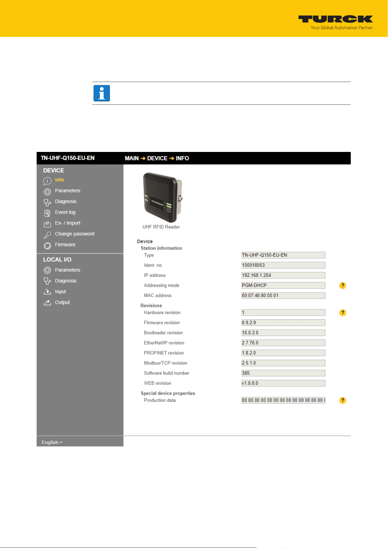
Setting
Setting RFID interfaces via the web server
TURCK GmbH | T +49 208 4952-0 | [email protected] | www.turck.com
V02.00 | 2025/09 | 114
8.5.2 Editing settings in the web server
A login is required to edit settings via the web server. The default password is "password".
NOTE
TURCK recommends changing the password after the first login for security reasons.
Open the device’s web server.
Enter Username and Password.
Click Login
After the login, you have write access to input and output data and to parameter data.
Fig.62: Web server – Home page after login
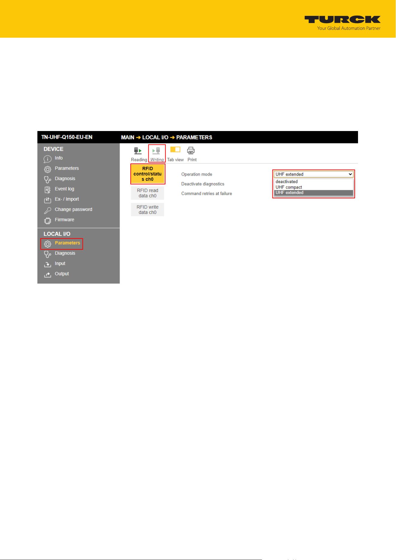
Setting
Setting RFID interfaces via the web server
TURCK GmbH | T +49 208 4952-0 | [email protected] | www.turck.com
V02.00 | 2025/09 | 115
Example: Setting the Operating Mode
In the following example, the operating mode is set to UHF extended.
Click Local I/Os Ò Parameter in the navigation bar on the left of the screen.
Select the RFID channel (here: RFID control/status ch0).
Select UHF extended mode from the Operation mode drop-down menu.
Save settings: Click Write.
If necessary, print the station report using the Print button.
Fig.63: Setting the Operating Mode
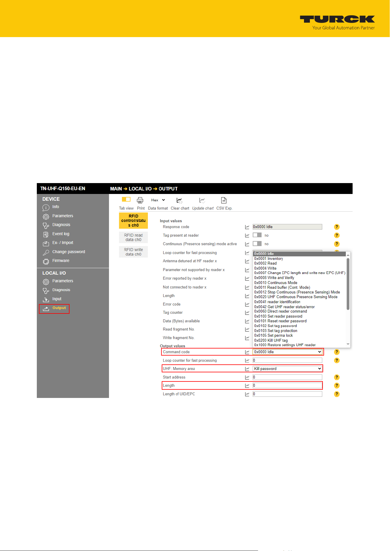
Setting
Setting RFID interfaces via the web server
TURCK GmbH | T +49 208 4952-0 | [email protected] | www.turck.com
V02.00 | 2025/09 | 116
Example: Executing a read command
In the following example, the reader reads 8bytes of data from a tag.
Click Local I/Os Ò Output in the navigation bar on the left of the screen.
Select RFID control/status ch0.
For UHF: Memory area, select USER from the drop-down menu.
Enter the number of bytes to be read in the Length entry field (here: 8).
Select the read command via the Command code drop-down menu: 0x0002 Read.
ð The read command is sent.
a The receipt of the command is confirmed automatically in the input data under Input
values Ò Response code with 0x8002 Busy — Read.
a The read command is executed as soon as a tag is present in the detection range of the
read/write head.
a The read data can be called under Local I/Os Ò Input.
Fig.64: Setting a read command in the web server

Operation
Executing a command and calling data
TURCK GmbH | T +49 208 4952-0 | [email protected] | www.turck.com
V02.00 | 2025/09 | 117
9 Operation
NOTE
The read and write data stored in the device is reset after a power reset.
9.1 Executing a command and calling data
NOTE
A command is successful when the response code is the same as the command
code.
Set the parameters for the command.
Set command code.
a Set the command code. The command is successful when the response code is the same
as the command code and no error message is present.
9.1.1 Typical times for command processing via a controller
The values shown in the following table are approximate values. The typical times for com-
mand execution depend on the following factors:
n Hardware configuration
n Software configuration
n Number of bus stations
n Bus cycle times
UHF applications
Command System cycle time Required time Dependence on factors such
as protocol, system etc.
Read 12 bytes EPC 4 ms 120…220 ms not detectable
Write 12 bytes EPC 4 ms 260…400 ms not detectable
Read 1 kByte 4 ms 2500 ms ≤ 20 %
Write 1 kByte 4 ms 7300 ms ≤ 20 %
Inventory (100 tags, read/
write head in report mode,
dynamic application)
4 ms 5500 ms ≤ 20 %
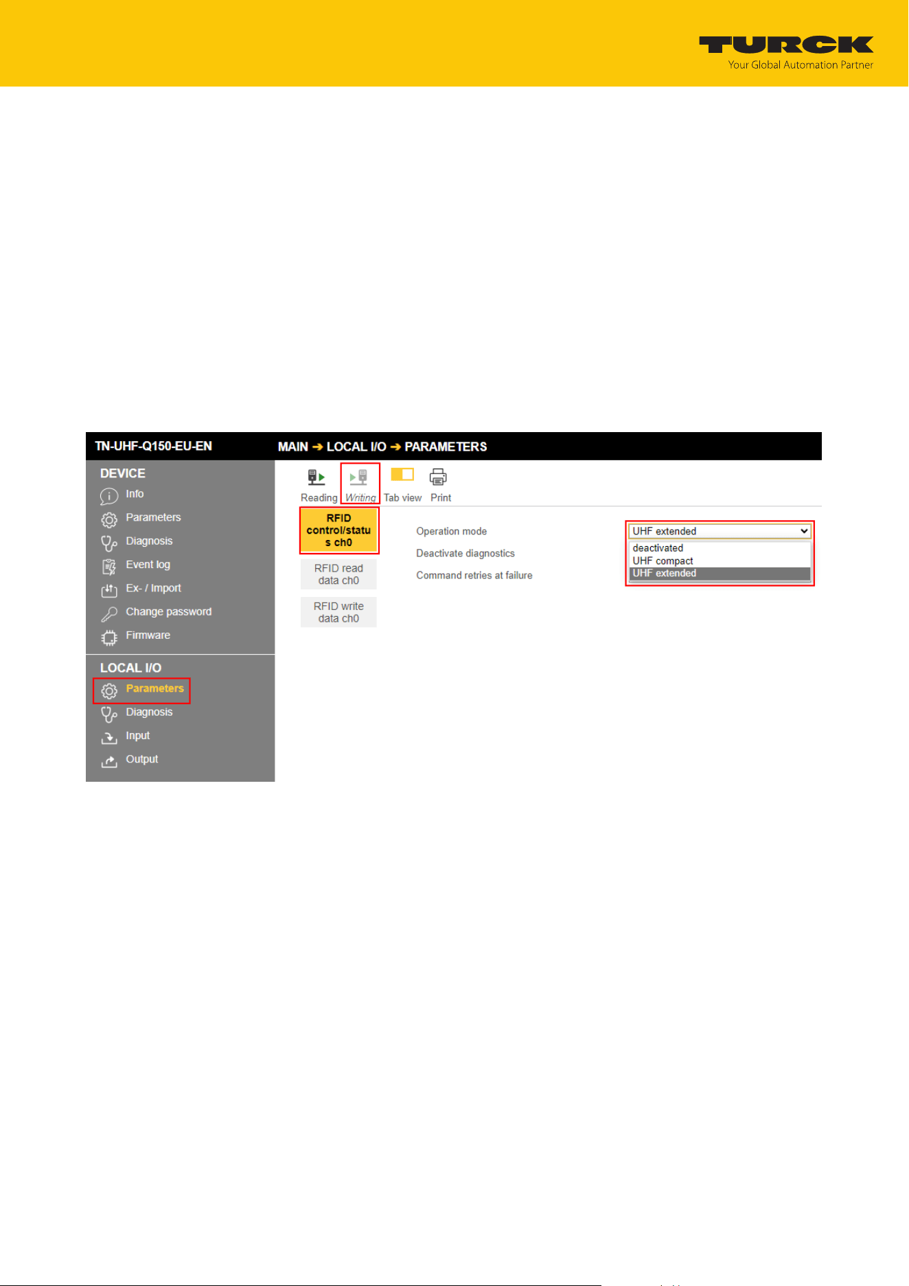
Operation
Use fragmentation
TURCK GmbH | T +49 208 4952-0 | [email protected] | www.turck.com
V02.00 | 2025/09 | 118
9.2 Use fragmentation
If more data is read than the set size of the data interface, the fragment counter in the input
data is incremented automatically.
To read more data: increase the fragment counter in the output data.
Repeat the process until the read or write fragment No. in the input data equals 0.
If less data is read than the set size of the data interface, the fragment counter stays at 0.
9.2.1 Example: Using fragmentation in the web server — read
The following example describes the reading of 500 bytes in fragments of 128 bytes each.
Open the web server of the device.
Log into the device as administrator.
Local I/Os Ò Parameter Ò Operating mode: Set to UHF extended.
Click Write to save.
Fig.65: Fragmentation – selecting the operating mode
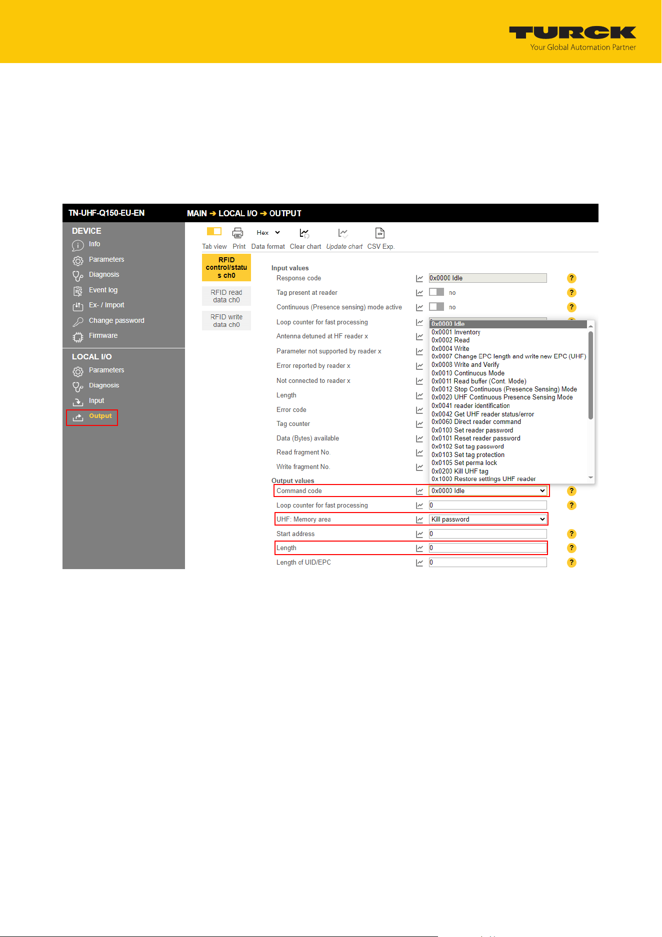
Operation
Use fragmentation
TURCK GmbH | T +49 208 4952-0 | [email protected] | www.turck.com
V02.00 | 2025/09 | 119
Click Local I/Os Ò Output in the navigation bar on the left of the screen.
Output values Ò Length: Enter the total number of bytes to be read (here: 500). Observe
the size of the tag.
For UHF: Memory area, select USER from the drop-down menu.
Select the read command via the Command code drop-down menu: 0x0002 Read.
a The read command is executed as soon as a tag is present in the detection range of the
reader.
Fig.66: Fragmentation – setting the read command
The following information is displayed in the Input values:
n Response code: Read command successfully executed
n Data (bytes) available: number of bytes that are still stored on the reader and are not yet
displayed in the read data
n Read fragment No.: sequential number of the next fragment to be read
The first 128 bytes of the input data are displayed under Input buffer.
At Read fragment No., enter the sequential number of the next fragment to be read.
The information displayed in the Input values is updated.
The second 128 bytes of the input data are displayed under Input buffer.
Repeat the operation until no more data is present on the reader.
a If no more data is present on the reader, Read fragment No. will show the value 0.
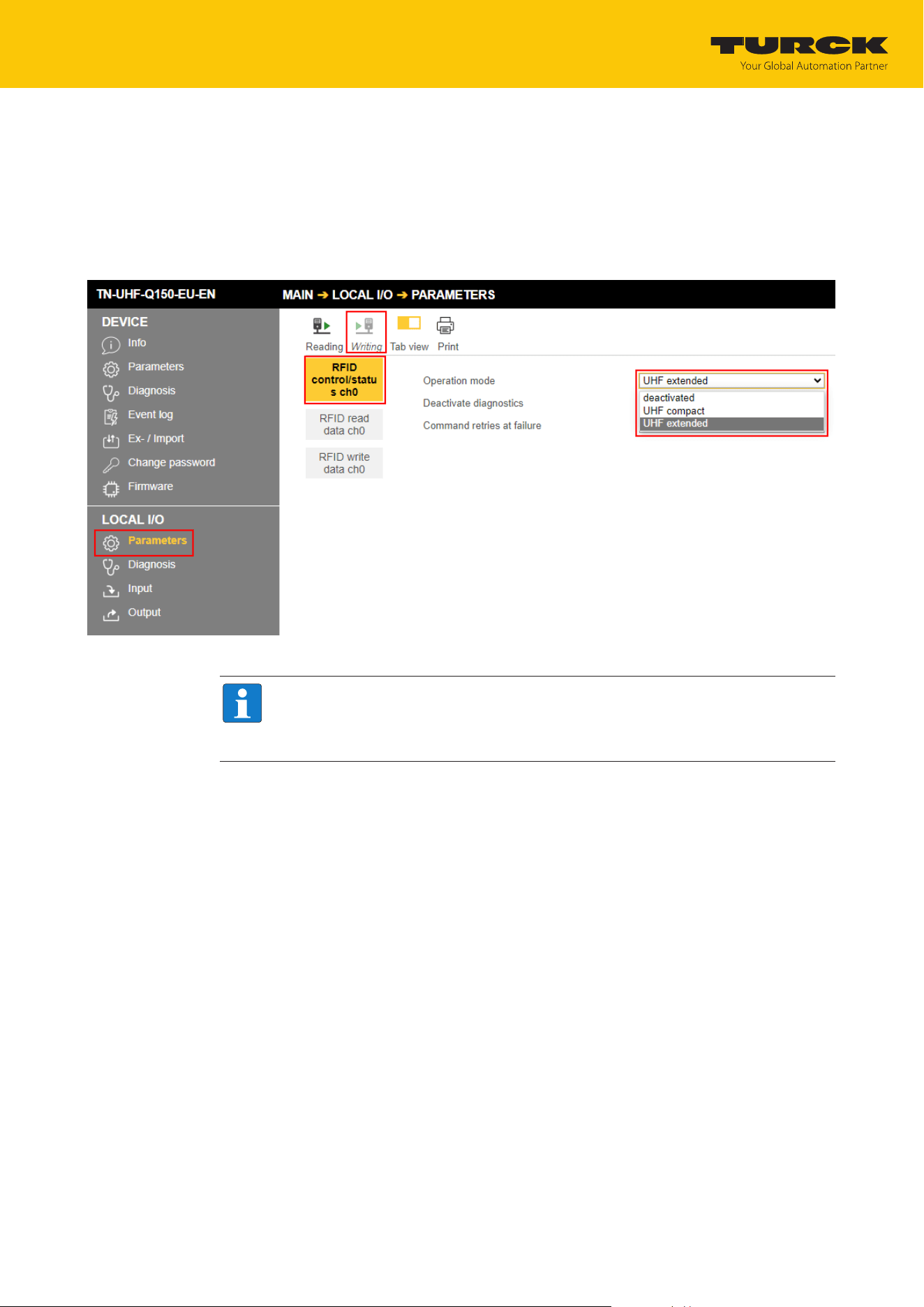
Operation
Use fragmentation
TURCK GmbH | T +49 208 4952-0 | [email protected] | www.turck.com
V02.00 | 2025/09 | 120
9.2.2 Example: Using fragmentation in the web server — write
The following example describes the writing of 500 bytes in fragments of 128 bytes each.
Open the web server of the device.
Log into the device as administrator.
Local I/Os Ò Parameter Ò Operating mode: Set to UHF extended.
Click Write to save.
Fig.67: Fragmentation – selecting the operating mode
NOTE
The tag must not leave the detection range of the read/write head during the write
operation.
The write fragment number must always start with 1.
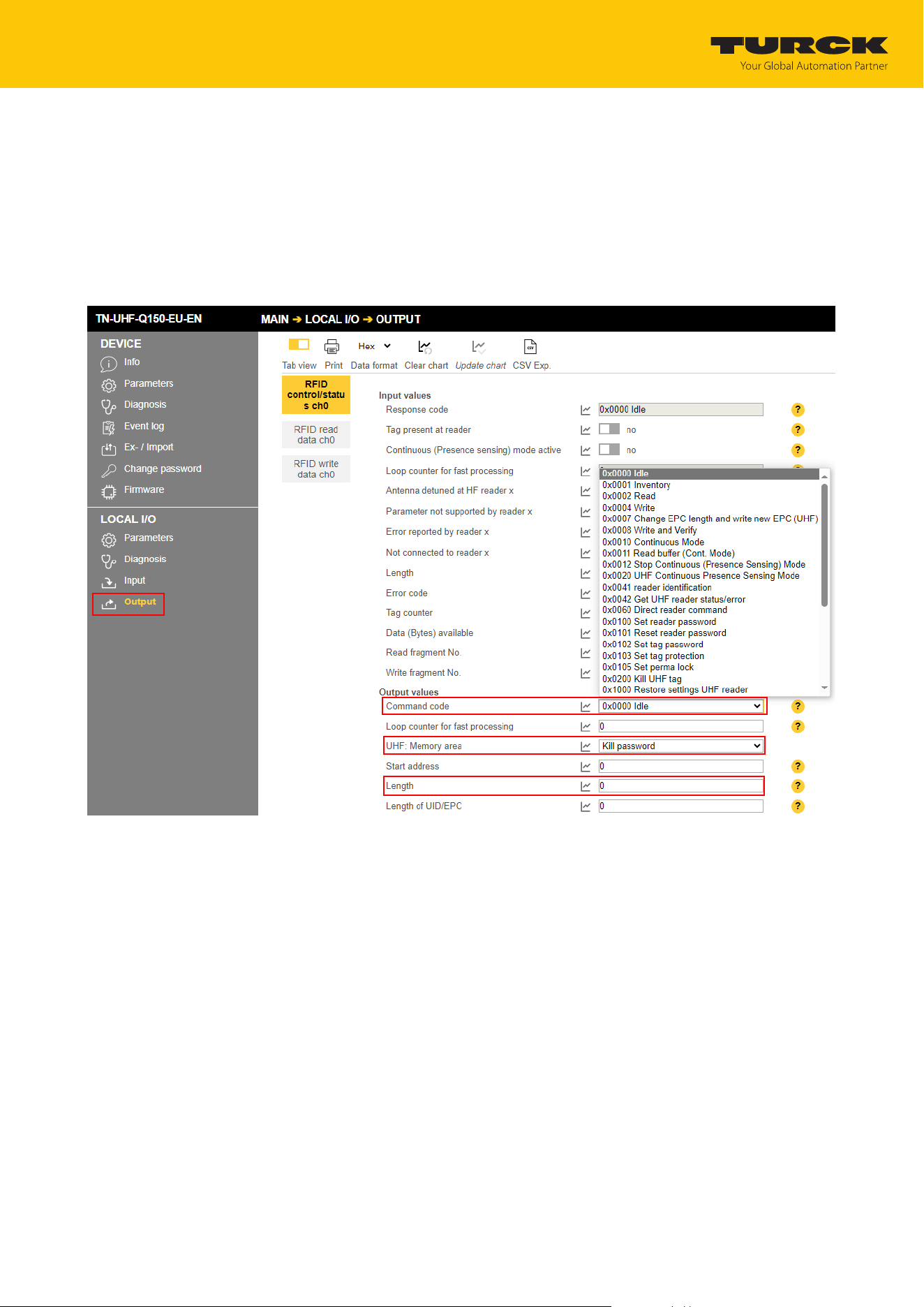
Operation
Use fragmentation
TURCK GmbH | T +49 208 4952-0 | [email protected] | www.turck.com
V02.00 | 2025/09 | 121
Enter the first 128 bytes of write data under Output buffer.
Click Local I/Os Ò Output in the navigation bar on the left of the screen.
Output values Ò Length: Enter the total number of bytes to be written (here: 500). Ob-
serve the size of the tag.
For UHF: Memory area, select USER from the drop-down menu.
Select the write command via the Command code drop-down menu: 0x0004 Write.
a The write command is executed as soon as a tag is present in the detection range of the
reader.
Fig.68: Fragmentation – executing a write command

Operation
Using commands with a loop counter function
TURCK GmbH | T +49 208 4952-0 | [email protected] | www.turck.com
V02.00 | 2025/09 | 122
The following information is displayed in the Input values:
n Response code: 0x8004 Busy — Write (write command active)
n Data (bytes) available: number of bytes that are still stored in the reader and were not yet
written to the tag
n Write fragment No.: sequential number of the fragment with the write data (here: 1)
Enter the second 128 bytes of write data under Output buffer.
Under Write fragment No., enter the sequential number of the next fragment with the
write data (here: 2).
If a tag is in the detection range, it is written directly. If there is no tag in the detection range,
the data is stored in the reader.
The tag must stay in the detection range until the command is fully executed. The device out-
puts a fault signal if the tag is removed from the detection range before the command has
been completed.
Repeat the operation until all data is present on the reader.
a If the data was successfully written to the tag, the Response code changes to 0x0004
Write.
9.3 Using commands with a loop counter function
NOTE
The loop counter is only supported for fast execution commands.
Setting the command: Enter the command code.
Set the loop counter to 1.
a The command was successfully executed if the same command code appears in the pro-
cess input data as in the process output data. The RFID data is stored in the buffer of the
interface.
Repeating the command: Increase the loop counter in the output data by 1.
a The command was successfully executed if the same loop counter value appears in the
process input data as in the process output data. The RFID data is stored in the buffer of
the interface.
Setting a new command: Enter the new command code and set the loop counter to 0.

Operation
Using the UHF password function
TURCK GmbH | T +49 208 4952-0 | [email protected] | www.turck.com
V02.00 | 2025/09 | 123
9.4 Using the UHF password function
A write protection for EPC and USER memory area can be set with an access password. If a Kill
password is set, the UHF tag can be mechanically destroyed with a Kill command. The access
password and the Kill password can also be protected from read or write accesses.
9.4.1 Setting the Kill password
The Kill UHF tag command is used to make the tag unusable. After a kill command, the tag can
neither be read nor written. A kill command cannot be reversed. A kill password must be set be-
forehand in order to execute a kill command.
Transfer the kill password to the relevant memory area of the tag:
– Password: Write data (0…3) with 4 bytes
– Command code 0x0004 (Write)
– Memory area: Kill password
Deactivate the tag irrevocably:
– Command code 0x0200 (Kill UHF tag)
NOTE
The tag can also be protected with an access password Setting the access password,
so that a Kill command can only be executed with a valid access password in tag and
reader.

Operation
Use CODESYS function blocks
TURCK GmbH | T +49 208 4952-0 | [email protected] | www.turck.com
V02.00 | 2025/09 | 124
9.5 Use CODESYS function blocks
Two function blocks are provided for simple integration into (existing) CODESYS programs:
n FB_Compact
n FB_Extended
Function Block Operating mode
FB_Compact UHF compact
FB_Extended UHF Advanced
The function blocks are part of the CODESYS package.
xExecute
xAbort
udiTimeOut
eCommand
rStatusMapping
rContrlMapping
udiStartAddress
uiDataLength
pReadDataMapping
pWriteDataMapping
pDataTx
pDataRx
BOOL
BOOL
UDINT
COMMAND
REFERENCE TO Compact input_t
REFERENCE TO Compact output_t
UDINT
UINT
POINTER TO BYTE
POINTER TO BYTE
POINTER TO BYTE
POINTER TO BYTE
BOOL
BOOL
BOOL
BOOL
ERROR
BOOL
BOOL
UINT
xDone
xBusy
xError
xAborted
eError
xTP
xRWHeadNotConnected
uiDataRxLength
FB_Compact
Fig.69: FB_Compact function block
xExecute
xAbort
udiTimeOut
eCommand
rStatusMapping
rContrlMapping
udiStartAddress
usiUHFMemoryArea
uiDataLength
siLengthOfUidEpc
pReadDataMapping
pWriteDataMapping
pDataTx
pDataRx
BOOL
BOOL
BOOL
BOOL
ERROR
BOOL
BOOL
UINT
UINT
xDone
xBusy
xError
xAborted
eError
xTP
xRWHeadNotConnected
uiTagCounter
uiDataRxLength
FB_Extended
BOOL
BOOL
UDINT
COMMAND
REFERENCE TO Extended input_t
REFERENCE TO Extended output_t
UDINT
USINT
UINT
SINT
POINTER TO BYTE
POINTER TO BYTE
POINTER TO BYTE
POINTER TO BYTE
Fig.70: FB_Extended function block

Operation
Use CODESYS function blocks
TURCK GmbH | T +49 208 4952-0 | [email protected] | www.turck.com
V02.00 | 2025/09 | 125
Function blocks — Input variables
Name Data type Meaning
xExecute BOOL 0 Ò 1 Ò 0: Execute command
1 Ò 0 Ò 1: Reset outputs
The outputs can only be reset if an action was
stopped or aborted by the user or an error oc-
curred beforehand.
xAbort BOOL 0 Ò 1 Ò 0: Abort command execution. All out-
puts are reset to the initial value.
udiTimeOut UDINT Time in µS after which the function block auto-
matically stops command execution
eCommand COMMAND Command code in hexadecimal format, RFID
channels — overview of commands
rStatusMapping REFERENCE TO
Compact Input_t
or
Extended Input_t
Start address of the process input data
rContrlMapping REFERENCE TO
Compact Out-
put_t or
Extended Out-
put_t
Start address of the process output data
udiStartAddress UDINT Start address for the selected command, e.g.
start address in the memory of the tag
usiUHFMemoryArea USINT n Domain 0: Kill password
n Domain 1: EPC
n Domain 2: TID
n Domain 3: User memory
n Domain 4: Access password
n Domain 5: PC (size of EPC)
n Other: Reserved
uiDataLength UINT Length for the selected command, e.g. length
of the data to be read or written
siLengthOfUidEpc SINT Entry for the EPC or UID length for addressing
a specific tag to be read or written. The UID or
EPC must be defined in the write data.
0: Size of the EPC or UID not checked
-1: NEXT mode: A tag is always only read if the
UID or EPC is different from the UID or EPC of
the last read or written tag.
Only the values 0, -1 and 8 are possible in HF
applications.
pReadDataMapping POINTER TO BYTE Start address in the input data (ARRAY[…] OF
BYTE)
pWriteDataMapping POINTER TO BYTE Start address in the output data (ARRAY[…] OF
BYTE)
pDataTx POINTER TO BYTE Write data (ARRAY[…] OF BYTE)
pDataRx POINTER TO BYTE Read data (ARRAY[…] OF BYTE)

Operation
Use CODESYS function blocks
TURCK GmbH | T +49 208 4952-0 | [email protected] | www.turck.com
V02.00 | 2025/09 | 126
Function blocks — output variables
Name Data type Meaning
xDone BOOL 1: Command successfully executed
0: Command not executed
xBusy BOOL 1: Command active but not yet completed;
system is waiting for execution, e.g. on tag in
the detection area
0: No command active
xError BOOL 1: Error detected, command execution aborted
0: No error detected
xAborted BOOL 1: Command execution aborted by user
0: Command execution not aborted
eError ERROR Error code, Reading error codes
xTP BOOL 1: Tag in detection range
0: No tag within the detection range
stTP BusModeTP_t 1: Tag in detection range
0: No tag within the detection range
Each bit corresponds to a tag on an individual
read/write head (max. 32 tags simultaneously).
xRWHeadNotConnected BOOL 1: No read/write head connected
0: Read/write head connected
uiTagCounter UINT Displays the number of detected tags. In HF
multi-tag applications and in UHF applications,
tags are only counted with an inventory com-
mand. In HF single-tag applications, all tags
detected by the read/write head are counted.
The tag counter is reset after the following
commands:
n Inventory (exception: single-tag applica-
tions)
n Continuous Mode
n Continuous presence sensing mode
n Reset
uiDataRxLength UINT Length for the selected command, e.g. length
of the data read or written
siLengthOfUidEpc SINT Entry for the EPC or UID length for addressing
a specific tag to be read or written. The UID or
EPC must be defined in the write data.
0: Size of the EPC or UID not checked
-1: NEXT mode: A tag is always only read if the
UID or EPC is different from the UID or EPC of
the last read or written tag.
Only the values 0, -1 and 8 are possible in HF
applications.
pReadDataMapping POINTER TO BYTE Start address in the input data (ARRAY[…] OF
BYTE)
pWriteDataMapping POINTER TO BYTE Start address in the output data (ARRAY[…] OF
BYTE)
pDataTx POINTER TO BYTE Write data (ARRAY[…] OF BYTE)
pDataRx POINTER TO BYTE Read data (ARRAY[…] OF BYTE)

Operation
Using Inventory command and Continuous (Presence Sensing) Mode
TURCK GmbH | T +49 208 4952-0 | [email protected] | www.turck.com
V02.00 | 2025/09 | 127
9.6 Using Inventory command and Continuous (Presence Sensing) Mode
The Inventory command and Continuous (presence sensing) mode transfer data to the PLC in
different ways. Continuous mode is suitable for high-speed applications in which a command
(e.g. read or write) is to be performed repeatedly. Repeated execution of the same command
by the controller is unnecessary.
The most important differences between an Inventory command and continuous mode are lis-
ted below:
Inventory Continuous Mode Continuous presence sensing
mode
Triggered reading of EPCs n Repeated reading of
EPCs
n Automatic repetition of the
same command (e.g. in-
ventory, read, write)
n UHF reader switches on as
soon as a tag is detected
n Repeated reading of
EPCs
n Automatic repetition of the
same command (e.g. in-
ventory, read, write)
Data is displayed in the read
data after the command has
ended.
Data must be read from the
memory of the interface with a
separate command.
Data must be read from the
memory of the interface with a
separate command.
Grouping of EPCs possible Grouping of EPCs possible Grouping of EPCs possible
No buffering on the read/write
device
No buffering on the read/write
device
No buffering on the read/write
device
Terminate command:
1. Timeout
2. Automatically after com-
mand execution
Terminate command:
1. Timeout
2. Terminating the Continu-
ous (Presence Sensing)
mode command or Reset
Terminate command:
1. Timeout
2. Terminating the Continu-
ous (Presence Sensing)
mode command or Reset

Operation
LEDs
TURCK GmbH | T +49 208 4952-0 | [email protected] | www.turck.com
V02.00 | 2025/09 | 128
9.7 LEDs
The device has the following LED indicators:
n Power supply
n Group and bus errors
n Status
n Diagnostics
PWR LED Meaning
off No power supply
green Power supply error-free
yellow Undervoltage within tolerance range
red Undervoltage outside of tolerance range
RFON LED Meaning
off RF field is switched off
green RF field is switched on
DATA LED Meaning
off No tag in the field, no data transfer
Yellow flashing Tag in the field, data transfer via the air interface
DIAG LED Meaning
off No error
red Error
BUS LED Meaning
Off No voltage present
Green Connection to a master active
Flashing 3 × green in
2s
ARGEE active
Green flashing (1 Hz) Device is operational
Red IP address conflict, Restore mode active, F_Reset active or Modbus
connection timeout
Red flashing Wink command active
Red/green (1 Hz) Autonegotiation and/or wait for IP address allocation in DHCP or
BootIP mode
ERR LED Meaning
Off No voltage present
Green No diagnostics
Red Diagnostics present

Operation
LEDs
TURCK GmbH | T +49 208 4952-0 | [email protected] | www.turck.com
V02.00 | 2025/09 | 129
ETH1 and ETH2 LEDs Meaning
Off No Ethernet connection
Green Ethernet connection established, 100 Mbit/s
Green flashing Data transfer, 100 Mbit/s
Yellow Ethernet connection established, 10 Mbit/s
Yellow flashing Data transfer, 10 Mbit/s
Operation
Software diagnostic messages
TURCK GmbH | T +49 208 4952-0 | [email protected] | www.turck.com
V02.00 | 2025/09 | 130
9.8 Software diagnostic messages
9.8.1 Diagnostic messages — gateway functions
Byte no. Bit
7 6 5 4 3 2 1 0
0 FCE COM V1
1 ARGEE DIAG
Meaning of the diagnostic bits
Designation Meaning
ARGEE ARGEE program active
DIAG Module diagnostics available
FCE DTM active in force mode
COM Internal error
V1 Undervoltage V1
9.8.2 Diagnostic messages — RFID channels
Byte no. Bit
7 6 5 4 3 2 1 0
0 Reserved PRMER DTM FIFO Reserved Reserved Reserved Reserved
1 Reserved TRE1 PNS1 Reserved Reserved Reserved Reserved Reserved
Meaning of the diagnostic bits
Designation Meaning
PRMER Parameterization error
DTM Configuration via DTM active
FIFO Buffer full
TRE… Reader reports error
PNS… Parameter not supported by the reader
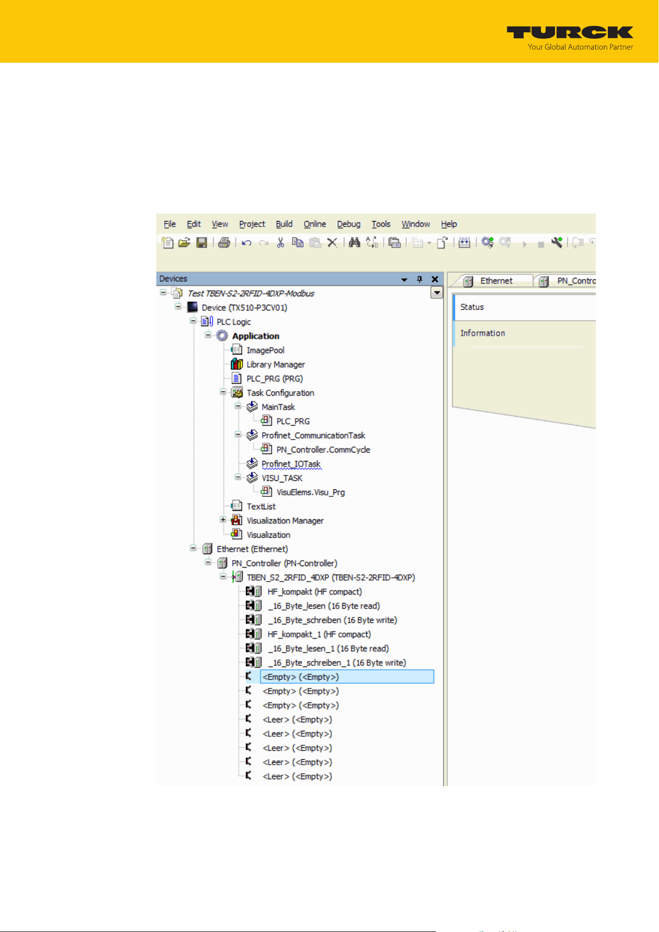
Operation
Example: Activating diagnostics via the PLC software
TURCK GmbH | T +49 208 4952-0 | [email protected] | www.turck.com
V02.00 | 2025/09 | 131
9.9 Example: Activating diagnostics via the PLC software
The following example describes the activating of diagnostic messages with CODESYS 3 in
PROFINET.
Insert the device in an existing project and connect to the controller (here: TURCK HMI
operation terminal TX510-P3CV01).
Right-click an empty slot.
Click Insert device.
Fig.71: Selecting an empty slot for diagnostics
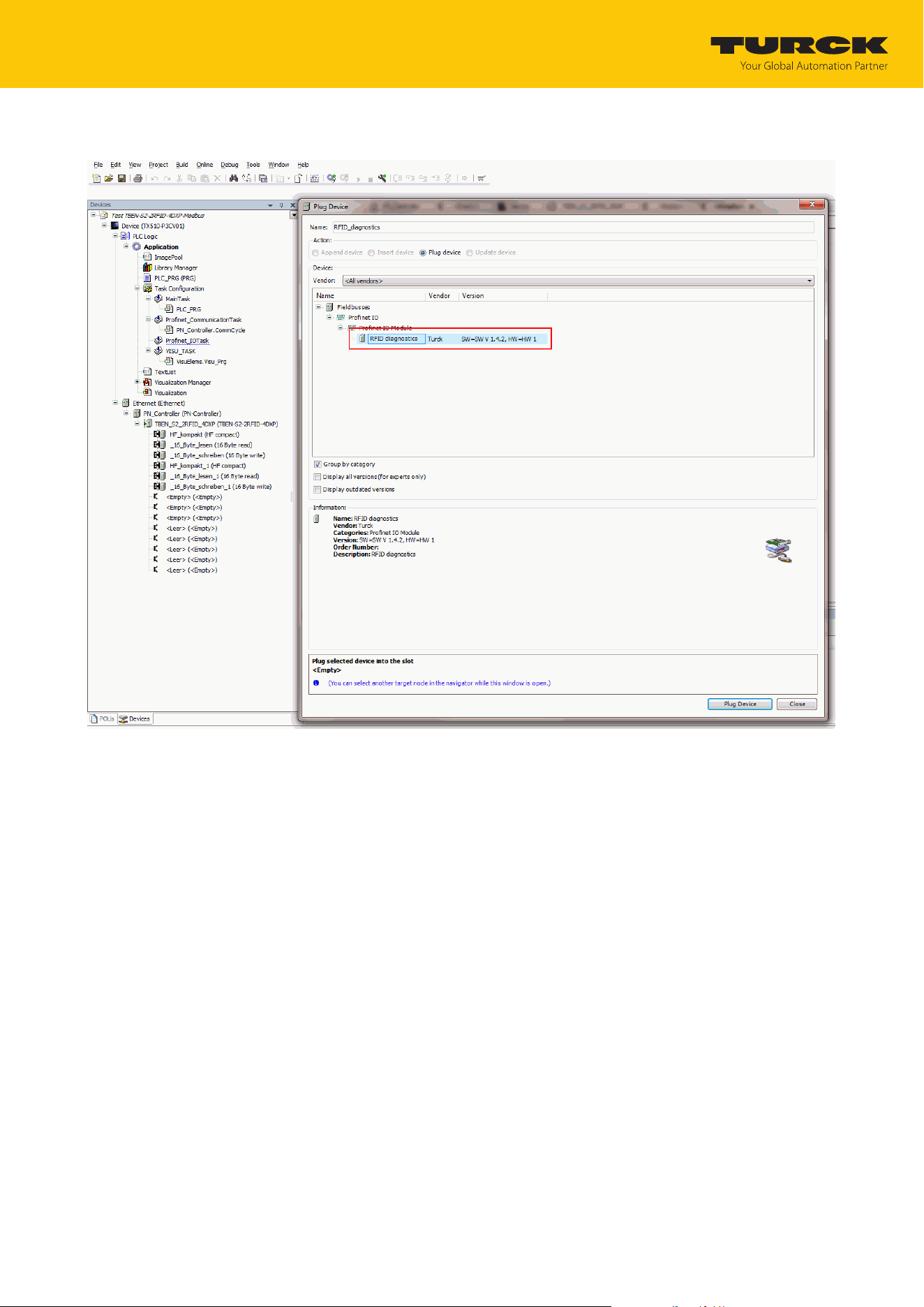
Operation
Example: Activating diagnostics via the PLC software
TURCK GmbH | T +49 208 4952-0 | [email protected] | www.turck.com
V02.00 | 2025/09 | 132
Click RFID diagnostics.
Fig.72: Selecting RFID diagnostics
Do not close the window.
The diagnostics can be read via the control program.

Operation
Reading error codes
TURCK GmbH | T +49 208 4952-0 | [email protected] | www.turck.com
V02.00 | 2025/09 | 133
9.10 Reading error codes
The error codes are part of the process input data.
Error code (hex.) Error code (dec.) Meaning
0x8000 32768 Channel not active
0x8001 32769 Read/write head not connected
0x8002 32770 Memory full
0x8003 32771 Block size of the tag not supported
0x8004 32772 Length exceeds the size of the read fragment
0x8005 32773 Length larger than the size of the write fragment
0x8007 32775 When an address is allocated, only one read/write head may be connec-
ted.
0x8008 32776 Fragmenting must start with write fragment no. 1
0x8009 32777 Fragmenting incomplete. Write fragment no. >0 expected
0x8100 33024 Parameter undefined
0x8101 33025
Operation mode parameter outside of the permissible range
0x8102 33026
Tag type parameter outside of the permissible range
0x8103 33027
Operation mode parameter in Continuous mode outside of the permiss-
ible range
0x8104 33028
Length parameter in Continuous mode outside of the permissible range
0x8105 33029 Size of the write fragment outside of the permissible range
0x8106 33030 Size of the read fragment outside of the permissible range
0x8107 33031
Bypass time parameter outside of the permissible range
0x8108 33032
Address in Continuous mode parameter outside of the permissible range
0x8200 33280 Command code unknown
0x8201 33281 Command not supported
0x8203 33283 Command not supported in UHF applications
0x8204 33284 Command for multi-tag application with automatic tag detection not sup-
ported
0x8205 33285 Command for applications with automatic tag detection not supported
0x8206 33286 Command only supported for applications with automatic tag detection
0x8207 33287 Command not supported for multi-tag application
0x8209 33289 Length outside of the permissible range
0x820A 33290 Address outside of the permissible range
0x820B 33291 Length and address outside of the permissible range
0x820C 33292 No tag found
0x820D 33293 Timeout
0x820E 33294 Next command not supported in multi-tag mode
0x820F 33295 Length of the UID outside of the permissible range
0x8210 33296 Length outside of the tag specification
0x8211 33297 Address outside of the tag specification
0x8212 33298 Length and address outside of the tag specification
0x8213 33299 Memory area of the tag outside of the permissible range

Operation
Reading error codes
TURCK GmbH | T +49 208 4952-0 | [email protected] | www.turck.com
V02.00 | 2025/09 | 134
Error code (hex.) Error code (dec.) Meaning
0x8214 33300 Read/write head address outside of the permissible range
0x8215 33301 Value for timeout outside of the permissible range
0x8300 33536
Continuous mode command not activated
0x8302 33538 Grouping not supported for read commands
0x8304 33540 Grouping not supported for write commands
0x0801 2049 Write or read error
0x2000 8192 Kill command not successful
0x2200 8704 Automatic tuning active
0x2201 8705 Automatic tuning failed
0x2202 8706 Read/write head not tuned
0x2500 9472 Password function of the tag not supported
0x2501 9473 Password function not supported by the read/write head
0x2502 9474 Tag protection bit pattern not supported
0x2900 10496 Address outside of the block limits
0x2901 10497 Length outside of the block limits
0xC000 49152 Internal error (response of the read/write head too short)
0xC001 49153 Command not supported by read/write head version
0xB062 45154 Read/write head error when executing an inventory command
0xB067 45159 Read/write head error when executing a lock block command
0xB068 45160 Read/write head error when executing a read multiple block command
0xB069 45161 Read/write head error when executing a write multiple block command
0xB06A 45162 Error when reading the system information
0xB06B 45163 Error when reading the protection status of the tags
0xB0AD 45229 Error when setting the read/write head address
0xB0BD 45245 Error when setting the transfer rate
0xB0DA 45274 Error with the "Tag in detection range" function
0xB0E0 45280 Error when reading the read/write head version
0xB0E1 45281 Error when reading the advanced read/write head version
0xB0F1 45297 Error with automatic read/write head tuning
0xB0F8 45304 Error when resetting a command in Continuous mode
0xB0FA 45306 Error when outputting the response code
0xB0FF 45311 Error when resetting the read/write head
0xB0B3 45235 Error when setting the tag password
0xB0B6 45238 Error when setting the write or read protection
0xB0B8 45240 Error when reading the protection status of the memory area on the tag
0xB0C3 45251 Error when setting the password in the read/write head

Operation
Reading error codes
TURCK GmbH | T +49 208 4952-0 | [email protected] | www.turck.com
V02.00 | 2025/09 | 135
Error code (hex.) Error code (dec.) Meaning
0xD0… 53… UHF read/write head reports error
0xD001 53249 Error when resetting the UHF read/write head
0xD002 53250 Error when reading the read/write head version
0xD003 53251 Error when reading the read/write head version when a tag is in the detec-
tion range
0xD004 53252 Error when setting the read/write head address
0xD009 53257 Error with the parameter setting of the UHF read/write head
0xD00A 53258 Error setting the transfer speed and the operating mode of the UHF read/
write head
0xD00B 53259 Error when polling
0xD00D 53261 Error when reading the device status
0xD00E 53262 Error when resetting the internal status bit
0xD00F 53263 Error when setting the read/write head outputs and/or LEDs
0xD011 53265 Error when reading the internal malfunctions
0xD014 53268 Diagnostics error
0xD016 53270 Error with the heartbeat message
0xD017 53271 Error when outputting the user settings
0xD01B 53275 Error when emptying the message memory in Polling mode
0xD081 53377 Error when switching the UHF tag on/off
0xD083 53379 Error when reading from a tag
0xD084 53380 Error when writing to a tag
0xD085 53381 Software trigger error
0xD088 53384 Error when outputting a command in accordance with EPC Class1 Gen2
0xD100 53504 Error with the Backup function
0xD101 53505 Error with the Backup function (required memory not available)
0xD102 53506 Error when restoring a backup
0xD103 53507 Error when restoring a backup (no backup present)
0xD104 53508 Error when restoring a backup (backup data damaged)
0xD105 53509 Error when restoring the default settings
0xD106 53510 Error with the tag function
0xF0… 61… ISO-15693 error
0xF001 61441 ISO-15693 error: Command not supported
0xF002 61442 ISO-15693 error: Command not detected, e.g. incorrect input format
0xF003 61443 ISO-15693 error: Command option not supported
0xF00F 61455 ISO-15693 error: undefined error
0xF010 61456 ISO-15693 error: Addressed memory area not available
0xF011 61457 ISO-15693 error: Addressed memory area locked
0xF012 61458 ISO-15693 error: Addressed memory area locked and not writable
0xF013 61459 ISO-15693 error: Write operation not successful
0xF014 61460 ISO-15693 error: Addressed memory area could not be locked
0xF0A0…0xF0DF 61600…61663 Air interface error

Operation
Reading error codes
TURCK GmbH | T +49 208 4952-0 | [email protected] | www.turck.com
V02.00 | 2025/09 | 136
Error code (hex.) Error code (dec.) Meaning
0xF101 61697 Air interface error: CRC error
0xF102 61698 Air interface error: Timeout
0xF8… 63… UHF read/write head error
0xF820 63520 UHF read/write head: Command not supported
0xF821 63521 UHF read/write head: unspecified error
0xF822 63522 UHF read/write head: A valid password is expected before the command
is accepted.
0xF824 63524 UHF read/write head: Read process not possible (e.g. invalid tag)
0xF825 63525 UHF read/write head: Write process not possible (e.g. tag readable only)
0xF826 63526 UHF read/write head: Write or read error
0xF827 63527 UHF read/write head: Access to unknown address (e.g. memory area out-
side of the range)
0xF828 63528 UHF read/write head: The data to be sent is not valid.
0xF82A 63530 UHF read/write head: The command needs a long time to execute.
0xF82C 63532 UHF read/write head: The requested object is not in the persistent
memory.
0xF82D 63533 UHF read/write head: The requested object is not in the volatile memory.
0xF835 63541 UHF read/write head: The command is temporarily not permissible.
0xF836 63542 UHF read/write head: The Opcode is not valid for this type of configura-
tion memory.
0xF880 63616 UHF read/write head: No tag in the field
0xF881 63617 UHF read/write head: The EPC of the command does not match the EPC in
the detection range.
0xF882 63618 UHF read/write head: incorrect tag type in the command
0xF883 63619 Writing to a block failed
0xFFFE 65534 Timeout on the RS485 interface
0xFFFF 65535 Command aborted
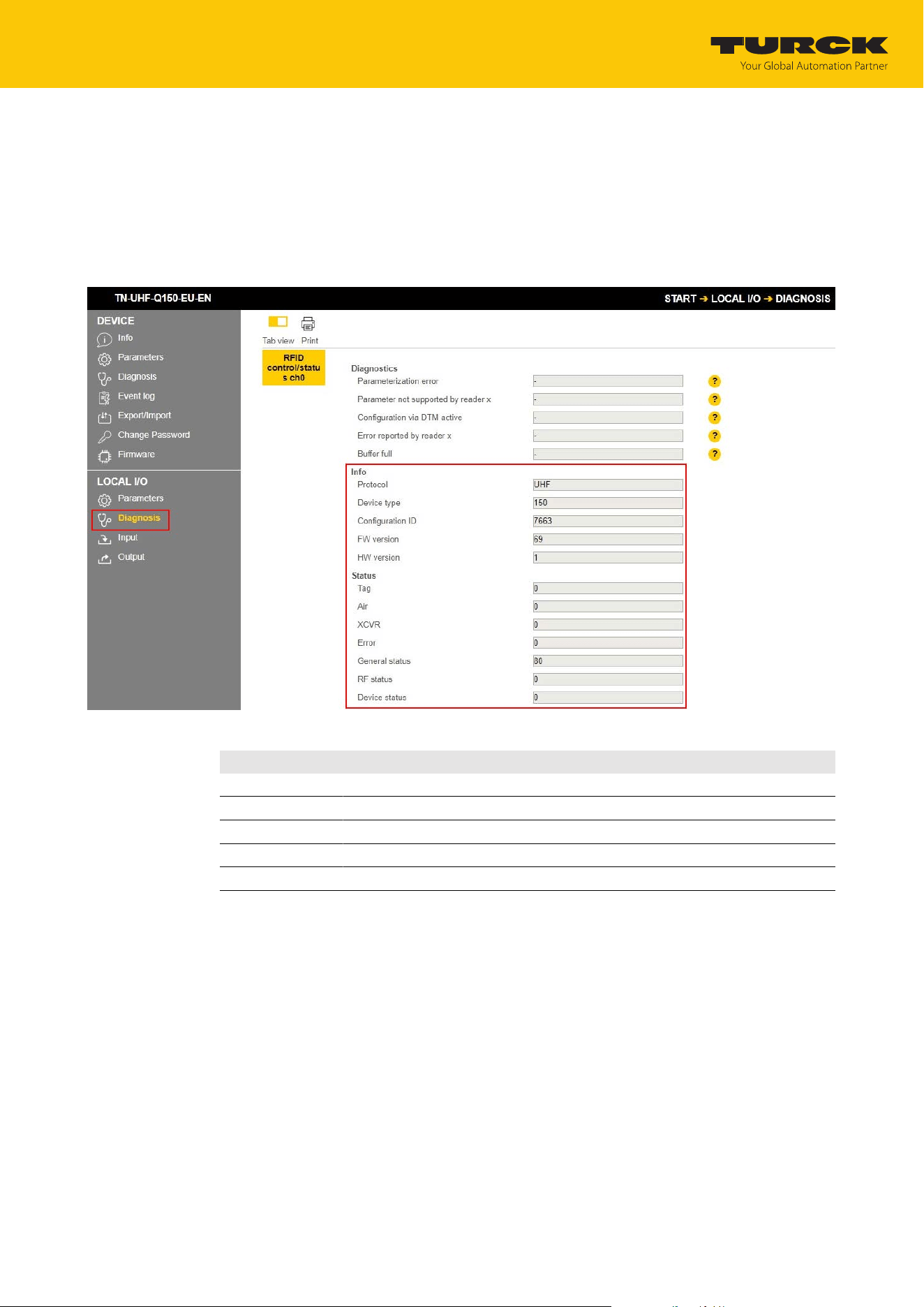
Operation
Using extended diagnostics — RFID channels
TURCK GmbH | T +49 208 4952-0 | [email protected] | www.turck.com
V02.00 | 2025/09 | 137
9.11 Using extended diagnostics — RFID channels
The extended diagnostics on the web server are used by TURCK service technicians for specific
troubleshooting.
To display extended diagnostics on the web server:
Open the web server and log in on the device.
LOCAL I/Os Ò Diagnostics.
Fig.73: Example: extended diagnostics
Info Description
Protocol Technology of the connected reader
Device type ID for the device type of the connected reader
Configuration ID ID for the configuration of the connected reader
FW version Firmware version of the connected reader
HW version Hardware version of the connected reader

Operation
Using extended diagnostics — RFID channels
TURCK GmbH | T +49 208 4952-0 | [email protected] | www.turck.com
V02.00 | 2025/09 | 138
Status Description Values
Error UHF reader
fault code
32: Command not supported
33: Unspecified error
34: A valid password is expected before the command is accepted.
36: Read process not possible (e.g. invalid tag)
37: Write process not possible (e.g. tag readable only)
38: Write or read error
39: Access to unknown address (e.g. memory area outside of the range)
40: The data to be sent is not valid.
42: The command needs a long time to execute.
44: The requested object is not in the persistent memory.
45: The requested object is not in the volatile memory.
53: The command is temporarily not permissible.
54: The Opcode is not valid for this type of configuration memory.
128: No tag in the field
129: The EPC of the command does not match the EPC in the detection
range.
130: Incorrect tag type specified in the command
131: Writing to a block failed
General status General status of UHF
reader
The displayed values result from the following bit structure:
Bit 1: Tag present
Bit 5: Test mode active
Bit 6: Read/write head configuration damaged, default settings are used.
Bit 7: Read/write head was reset (after reset).
RF status Status of the UHF
reader RF module
The displayed values result from the following bit structure:
Bit 0: PLL not locked
Bit 1: Reverse power too high
Bit 2: Antenna resistance too high or too low
Bit 3: No free channel available
Bit 4: Limit value for radiated power exceeded
Device status Device-specific status
information
The displayed values result from the following bit structure:
Bit 0: Configuration invalid. Command execution not possible.
Bit 1: Communication error
Bit 2: Temperature too high
Bit 3: Temperature warning
Bit 4: Error in message generation (in Polling mode outside of memory
area)
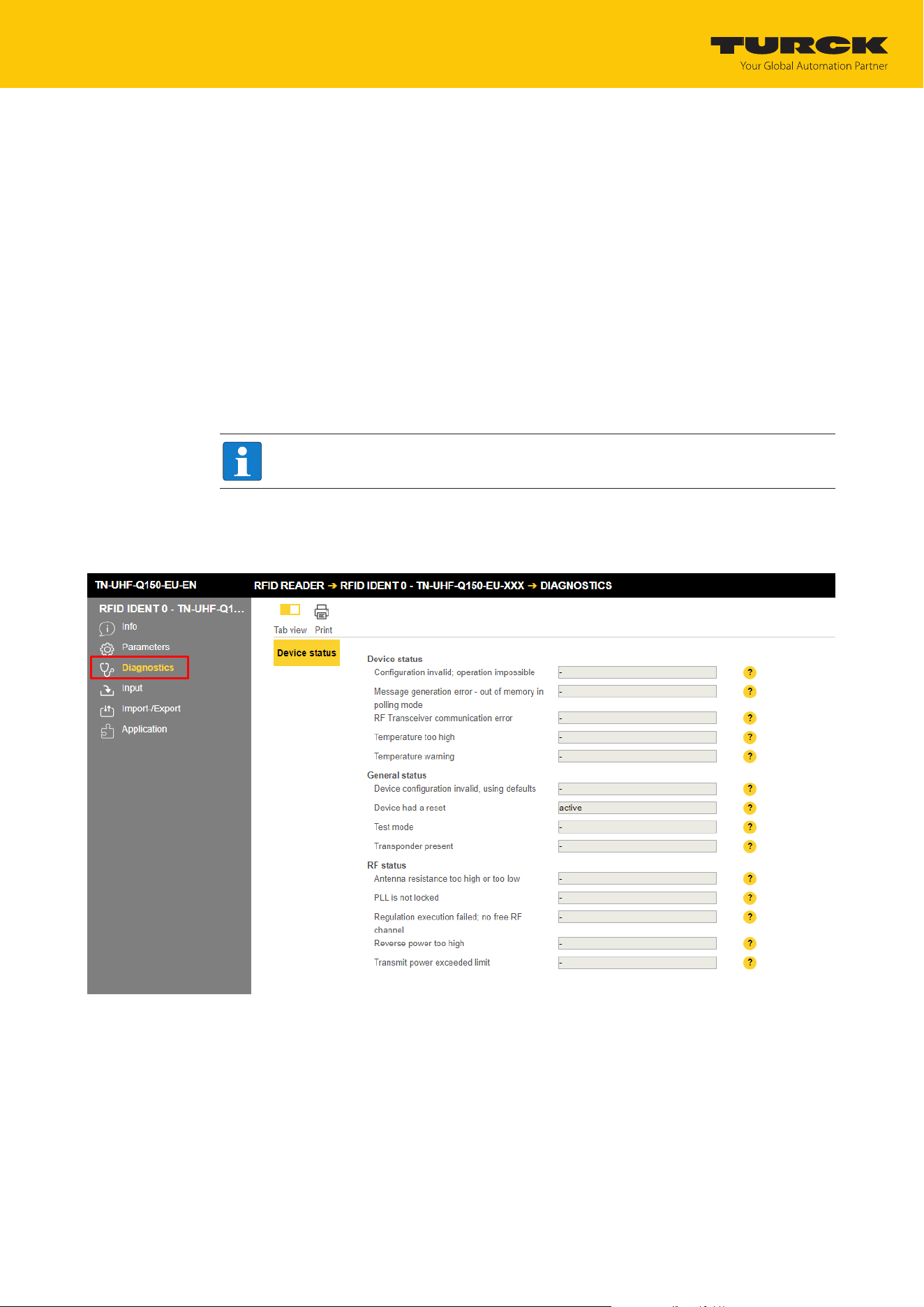
Troubleshooting
Rectifying errors
TURCK GmbH | T +49 208 4952-0 | [email protected] | www.turck.com
V02.00 | 2025/09 | 139
10 Troubleshooting
Proceed as follows if the device does not operate as expected:
Exclude environmental interference.
Check the terminals of the device for faults.
Check the device for parameter errors.
A device fault is present if the malfunction continues. In this case, decommission the device and
replace it with a new device of the same type.
10.1 Rectifying errors
Errors are displayed by an ERR LED lit red on the device.
Calling fault signals in the web server and rectifying them
NOTE
Contact TURCK if the error persists after the device is reset.
Log into the web server (see Editing settings in the web server).
Click Diagnostics in the navigation bar on the left of the screen.
a The fault signals are displayed in the device status.
Fig.74: Web server – Diagnostics
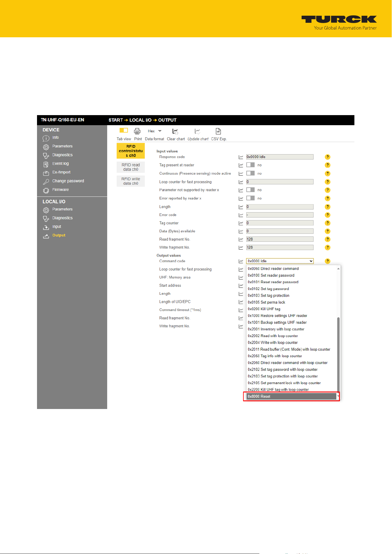
Troubleshooting
Rectifying errors
TURCK GmbH | T +49 208 4952-0 | [email protected] | www.turck.com
V02.00 | 2025/09 | 140
Rectifying fault signals:
Click Local I/O Ò Output in the navigation bar on the left of the screen.
Select RFID control/status ch0.
From the Command code drop-down menu, select the following reset command:
0x8000 Reset
a The reader is reset.
Fig.75: Web server — resetting the reader
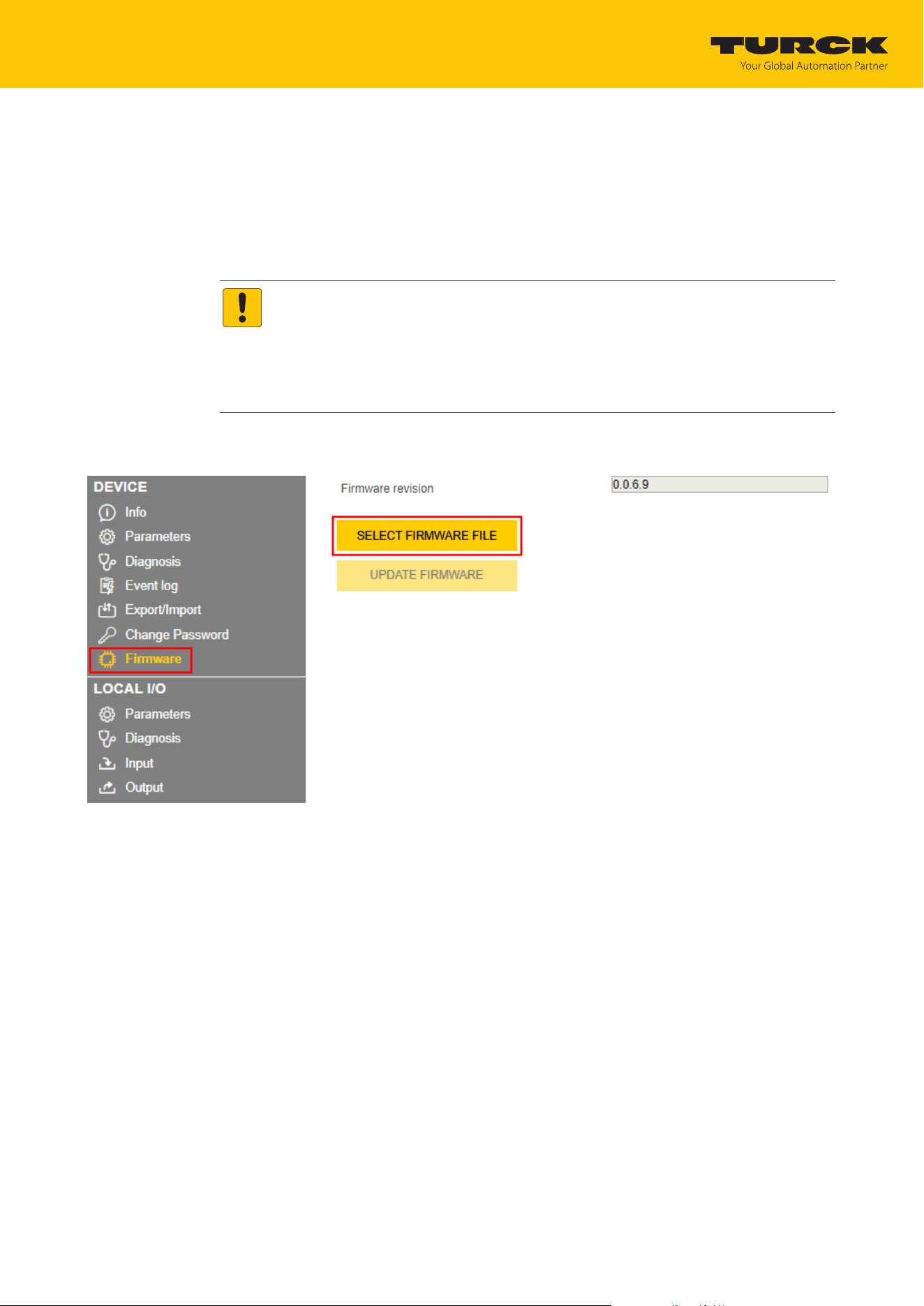
Maintenance
Updating the firmware via the Web server
TURCK GmbH | T +49 208 4952-0 | [email protected] | www.turck.com
V02.00 | 2025/09 | 141
11 Maintenance
Ensure regularly that the plug connections and cables are in good condition.
The devices are maintenance-free, clean dry if required.
11.1 Updating the firmware via the Web server
NOTICE
Interruption of the power supply during the firmware update
Risk of device damage due to faulty firmware update
Do not interrupt the power supply during the firmware update.
During the firmware update do not reset the power supply.
Do not interrupt the Ethernet connection during the firmware update.
Open the web server and log in on the device.
Click Firmware Ò SELECT FIRMWARE FILE.
Fig.76: Selecting the new firmware file
Select the storage location of the file and select the file.
Start the firmware update via the UPDATE FIRMWARE button.
ð The progress of the firmware update is displayed.
After a firmware update has been successfully completed, start the device by clicking OK.

Maintenance
Returning devices
TURCK GmbH | T +49 208 4952-0 | [email protected] | www.turck.com
V02.00 | 2025/09 | 142
12 Repair
The device is not intended for repair by the user. The device must be decommissioned if it is
faulty. Observe our return acceptance conditions when returning the device to TURCK.
12.1 Returning devices
If a device has to be returned, bear in mind that only devices with a decontamination declara-
tion will be accepted. This is available for download at
https://www.turck.de/en/return-service-6079.php
and must be completely filled in, and affixed securely and weather-proof to the outside of the
packaging.

Maintenance
TURCK GmbH | T +49 208 4952-0 | [email protected] | www.turck.com
V02.00 | 2025/09 | 143
13 Disposal
The devices must be disposed of properly and do not belong in the domestic waste.

Technical data
TURCK GmbH | T +49 208 4952-0 | [email protected] | www.turck.com
V02.00 | 2025/09 | 144
14 Technical data
Technical data
Electrical data
Operating voltage 12…30VDC
DC rated operational current ≤ 1200mA
Data transfer Electromagnetic AC field
Technology UHF RFID
Radio communication and protocol standards ISO 18000-63
EPCglobal Gen 2
Channel spacing 200 kHz
Output power ≤ 0.5 W (ERP), adjustable
Antenna polarization RHCP/LHCP, adjustable
Antenna HPBW 90°
Output function Read/write
Mechanical data
Mounting condition Non-flush
Ambient temperature -30…+50°C
Design rectangular
Dimensions 150×150×61.7mm
Housing material Aluminum, AL, silver
Material of active face Fiber glass reinforced polyamide, PA6-GF30,
black
Vibration resistance 55Hz (1mm)
Shock resistance 30g (11ms)
Protection class IP67
Electrical connection RP-TNC
Input impedance 50ohm
MTTF 49 years acc. to SN 29500 (Ed. 99) 20°C
RFID data interface UHF
Ethernet transfer rate 10/100Mbps
Connection technology Ethernet 2×M12, 4-pin, D-coded
Web server Default: 192.168.1.254
Modbus TCP
Addressing Static IP, BOOTP, DHCP
Supported function codes FC1, FC2, FC3, FC4, FC5, FC6, FC15, FC16, FC23
Number of TCP connections 8
EtherNet/IP
Addressing acc. to EtherNet/IP specification
Device Level Ring (DLR) Supported
Input Assembly Instance 103
Number of input data (PAE) 248
Output Assembly Instance 104
Number of output data (PAA) 248

Technical data
TURCK GmbH | T +49 208 4952-0 | [email protected] | www.turck.com
V02.00 | 2025/09 | 145
Technical data
Class 1 connections (CIP) 10
Class 3 connections (TCP) 3
Configuration Assembly Instance 106
PROFINET
Addressing DCP
MinCycleTime 4 ms
Diagnostics acc. to PROFINET alarm handling
Automatic addressing Supported
Media Redundancy Protocol (MRP) Supported
Number of input data (PAE) Max. 512
Number of output data (PAA) Max. 512

TURCK branches – contact data
TURCK GmbH | T +49 208 4952-0 | [email protected] | www.turck.com
V02.00 | 2025/09 | 146
15 TURCK branches — contact data
Germany
TURCK GmbH
Witzlebenstraße 7, 45472 Mülheim an der Ruhr
www.turck.de
Australia
Turck Australia Pty Ltd
Building 4, 19-25 Duerdin Street, Notting Hill, 3168 Victoria
www.turck.com.au
Austria
Turck GmbH
Graumanngasse 7/A5-1, A-1150 Vienna
www.turck.at
Belgium
Turck Multiprox N. V.
Lion d'Orweg 12, B-9300 Aalst
www.multiprox.be
Brazil
Turck do Brasil Automação Ltda.
Rua Anjo Custódio Nr. 42, Jardim Anália Franco, CEP 03358-040 São Paulo
www.turck.com.br
Canada
Turck Canada Inc.
140 Duffield Drive, CDN-Markham, Ontario L6G 1B5
www.turck.ca
China
Turck (Tianjin) Sensor Co. Ltd.
18,4th Xinghuazhi Road, Xiqing Economic Development Area, 300381
Tianjin
www.turck.com.cn
Czech Republic
TURCK s.r.o.
Na Brne 2065, CZ-500 06 Hradec Králové
www.turck.cz
France
TURCK BANNER S.A.S.
11 rue de Courtalin Bat C, Magny Le Hongre, F-77703 MARNE LA VALLEE
Cedex 4
www.turckbanner.fr
Hungary
TURCK Hungary kft.
Árpád fejedelem útja 26-28., Óbuda Gate, 2. em., H-1023 Budapest
www.turck.hu
India
TURCK India Automation Pvt. Ltd.
401-403 Aurum Avenue, Survey. No 109 /4, Near Cummins Complex,
Baner-Balewadi Link Rd., 411045 Pune - Maharashtra
www.turck.co.in
Italy
TURCK BANNER S.R.L.
Via San Domenico 5, IT-20008 Bareggio (MI)
www.turckbanner.it
Japan
TURCK Japan Corporation
ISM Akihabara 1F, 1-24-2, Taito, Taito-ku, 110-0016 Tokyo
www.turck.jp

TURCK branches – contact data
TURCK GmbH | T +49 208 4952-0 | [email protected] | www.turck.com
V02.00 | 2025/09 | 147
Korea
Turck Korea Co, Ltd.
A605, 43, Iljik-ro, Gwangmyeong-si
14353 Gyeonggi-do
www.turck.kr
Malaysia
Turck Banner Malaysia Sdn Bhd
Unit A-23A-08, Tower A, Pinnacle Petaling Jaya, Jalan Utara C,
46200 Petaling Jaya Selangor
www.turckbanner.my
Mexico
Turck Comercial, S. de RL de CV
Blvd. Campestre No. 100, Parque Industrial SERVER, C.P. 25350 Arteaga,
Coahuila
www.turck.com.mx
Netherlands
Turck B. V.
Ruiterlaan 7, NL-8019 BN Zwolle
www.turck.nl
Poland
TURCK sp.z.o.o.
Wroclawska 115, PL-45-836 Opole
www.turck.pl
Romania
Turck Automation Romania SRL
Str. Siriului nr. 6-8, Sector 1, RO-014354 Bucuresti
www.turck.ro
Sweden
Turck AB
Fabriksstråket 9, 433 76 Jonsered
www.turck.se
Singapore
TURCK BANNER Singapore Pte. Ltd.
25 International Business Park, #04-75/77 (West Wing) German Centre,
609916 Singapore
www.turckbanner.sg
South Africa
Turck Banner (Pty) Ltd
Boeing Road East, Bedfordview, ZA-2007 Johannesburg
www.turckbanner.co.za
Turkey
Turck Otomasyon Ticaret Limited Sirketi
Inönü mah. Kayisdagi c., Yesil Konak Evleri No: 178, A Blok D:4,
34755 Kadiköy/ Istanbul
www.turck.com.tr
United Kingdom
TURCK BANNER LIMITED
Blenheim House, Hurricane Way, GB-SS11 8YT Wickford, Essex
www.turckbanner.co.uk
USA
Turck Inc.
3000 Campus Drive, USA-MN 55441 Minneapolis
www.turck.us
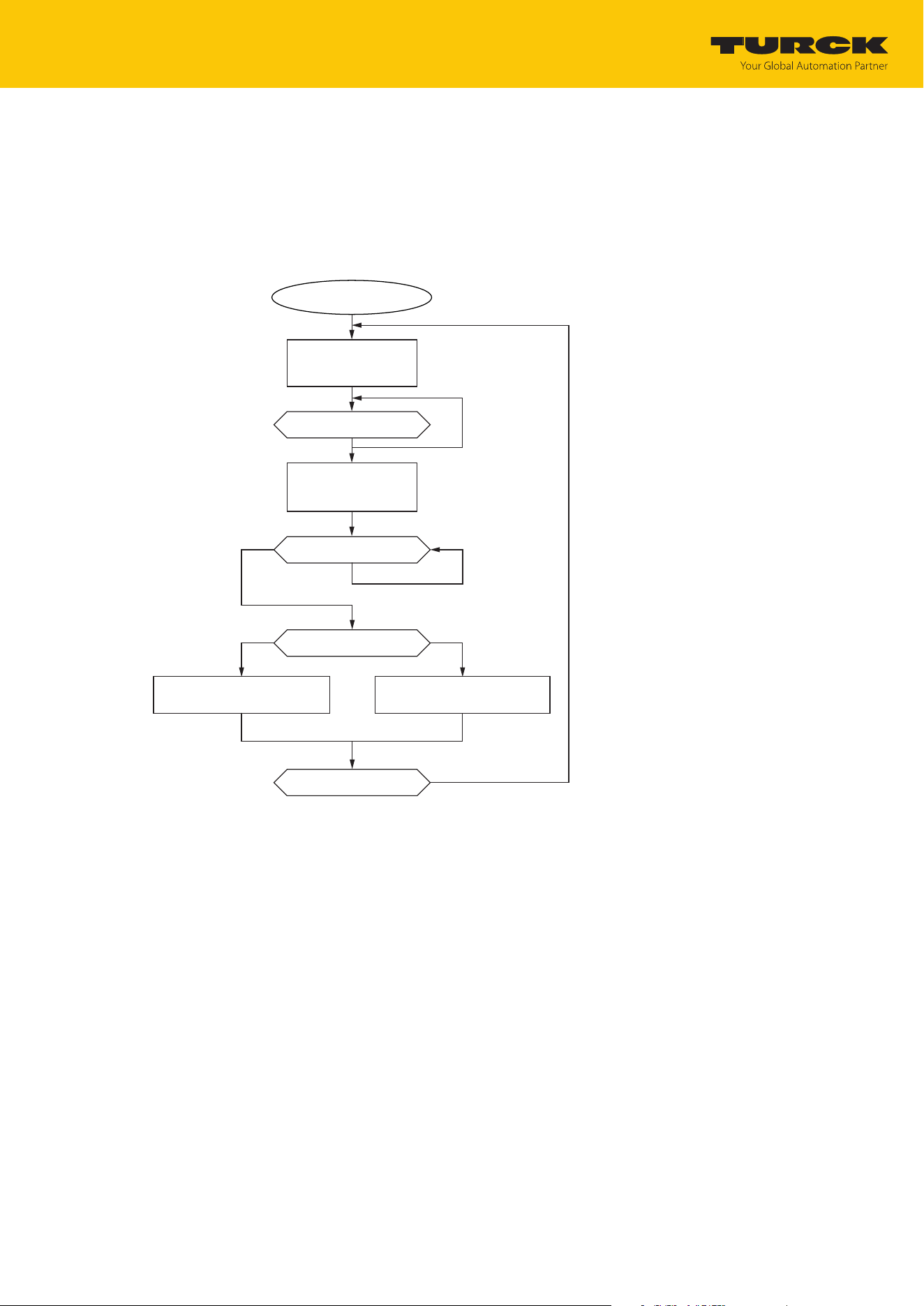
Appendix: Flow charts showing the operation of the device
Flow chart: command processing
TURCK GmbH | T +49 208 4952-0 | [email protected] | www.turck.com
V02.00 | 2025/09 | 148
16 Appendix: flow charts showing the operation of the device
The flow charts explain the operation of the device as well as the processing of commands.
16.1 Flow chart: command processing
busy
done
in.errorCode = 0x0000
done
in.errorCode = [0x0001…0xffff]
Start
in.responseCode <> 0
in.responseCode < 0x4000
new command desired?
in.responseCode ≤ 0
idle:
out.commandCode := 0
out.loopCount := 0
initiate command:
out.commandCode :=
0x0002 READ
yes no
Fig.77: Flow chart for command processing

Appendix: Flow charts showing the operation of the device
Flow chart: command processing
TURCK GmbH | T +49 208 4952-0 | [email protected] | www.turck.com
V02.00 | 2025/09 | 149
16.1.1 Handling command execution with Busy and Error — sample code in CODESYS
The following is a sample code for evaluation in the PLC program.
commandCode: INT;
responseCode: INT;
responseCodePrevious: INT;
commandCode:= 0x0002; (* READ *)
(* … PLC cycle … *)
IF (responseCode <> responseCodePrevious) THEN
IF (responseCode < 0) THEN
(* BUSY *)
ELSE
IF (responseCode == commandCode) THEN
(* success *)
ELSIF (0x8000 == commandCode) AND (0x0000 == responseCode) THEN
(* reset success *)
ELSE
(* error *)
END_IF;
END_IF;
responseCodePrevious:= responseCode;
END_IF;
Appendix: Flow charts showing the operation of the device
Flow chart: rapid command processing with loop counter
TURCK GmbH | T +49 208 4952-0 | [email protected] | www.turck.com
V02.00 | 2025/09 | 150
16.2 Flow chart: rapid command processing with loop counter
busy
done
in.errorCode = 0x0000
done
in.errorCode = [0x0001…0xffff]
Start
in.loopCout <> 0
or
in.responseCode <> 0
(in.loopCount <> out.loopCount)
or
in.responseCode ≤ 0
in.responseCode < 0x4000
new command desired?
idle:
out.commandCode := 0
out.loopCount := 0
initiate command:
out.loopCount :=
out.loopCount+1
select command:
out.commandCode :=
0x2002 LOOP_READ
yes no
Fig.78: Flow chart for fast command processing with loop counter
Appendix: Flow charts showing the operation of the device
Flow chart: command processing with fragmentation
TURCK GmbH | T +49 208 4952-0 | [email protected] | www.turck.com
V02.00 | 2025/09 | 151
16.3 Flow chart: command processing with fragmentation
busy
Start
in.responseCode < 0
in.readFragmentNo <> 0
out.readFragmentNo == in.readFragmentNo
in.responseCode < 0x4000
yes
yes
no
no
no
yes
in.loopCount <> 0
or
in.responseCode <> 0
idle:
out.loopCount := 0
out.commandCode := 0
out.writeFragmentNo := 0
out.readFragmentNo := 0
initiate command and send 1st fragment:
out.loopCount = out.loopCount+1
out.commandCode := [0x0001…0x3FFF]
out.length = length of writedata
out.writeFragmentNo := 1
out.writeData := part 1
send next fragment:
out.writeFragmentNo := out.writeFragmentNo+1
out.writeData := part 2…(n-1)
send last fragment:
out.writeFragmentNo := 0
out.readFragmentNo := 0
out.writeData := part n
in.errorCode = 0x0000
in.lengst = length of read data
in.readData = part 1
error
in.errorCode = [0x0001…0xffff]
acknowledge 1st fragment
out.readFragmentNo := in.readFragmentNo
in.readData = part 2…(n)
acknowledge next fragment
out.readFragmentNo := in.readFragmentNo
done
in.write FragmentNo <> out.writeFragmentNo
in.writeFragmentNo <> out.writeFragmentNo
more than one fragment left
new command desired?
Fig.79: Flow chart for command processing with fragmentation
Appendix: Flow charts showing the operation of the device
Flow chart: Continuous Mode with interruption before reading data
TURCK GmbH | T +49 208 4952-0 | [email protected] | www.turck.com
V02.00 | 2025/09 | 152
16.4 Flow chart: Continuous Mode with interruption before reading data
Set command:
Command Code = 0x0012
„Continous mode active“ = False
Data bytes available = 0
ERROR= TRUE
Error Code
OR
Read-Fragment +1
Yes
No
Done
Idle:
Command Code = 0
Response Code = 0
Response Code = Command Code
Set parameter:
„Length“ := data (bytes) available
Set command:
Command Code := 0x0011
Set command:
Command Code = 0x0010
Set output parameter:
- „Start address“ = 1
(Grouping EPCs for UHF)
- e.g. timeout
Yes
Manual stop Automatic stop
after timeout
Fig.80: Flow chart for Continuous Mode with interruption before reading data
Appendix: Flow charts showing the operation of the device
Flow chart: Continuous Mode without interruption before reading data
TURCK GmbH | T +49 208 4952-0 | [email protected] | www.turck.com
V02.00 | 2025/09 | 153
16.5 Flow chart: Continuous Mode without interruption before reading data
Data bytes available = 0
ERROR= TRUE
Error Code
Read-Fragment +1
Yes
No
Idle:
Command Code = 0
Response Code = 0
Response Code = Command Code
Set parameter:
„Length“ : define value
Set command:
Command Code := 0x0011
Set command:
Command Code := 0x0010
Set command:
Command Code := 0x0012
Set command:
Command Code := 0x0010
Set output parameter:
- „Start address“ := 1
(Grouping EPCs for UHF)
Yes
…
*)
*) After increasing the Read Fragment No., the new data will be shown in the read data input.
Fig.81: Flow chart for Continuous Mode without interruption before reading data
Appendix: Flow charts showing the operation of the device
Flow chart: programming tags with a password
TURCK GmbH | T +49 208 4952-0 | [email protected] | www.turck.com
V02.00 | 2025/09 | 154
16.6 Flow chart: programming tags with a password
write desired
data to tag
start
define password
command:
set_read/write_head_password
(
with default password
of tag
= 0000)
command:
set_read/write_head_password
(with new password)
command:
set_tag_password
(with new password)
command:
set_tag_protection
(define tag protection)
end
ERROR = TRUE
error code
response code = command code
ERROR = TRUE
er
ror code
response code = command code
Fig.82: programming tags with a password

Over 30 subsidiaries and
60 representations worldwide!
www.turck.com
100046949 | 2025/09
100046949