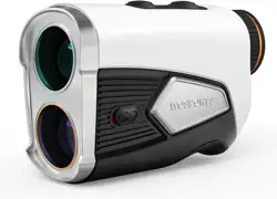
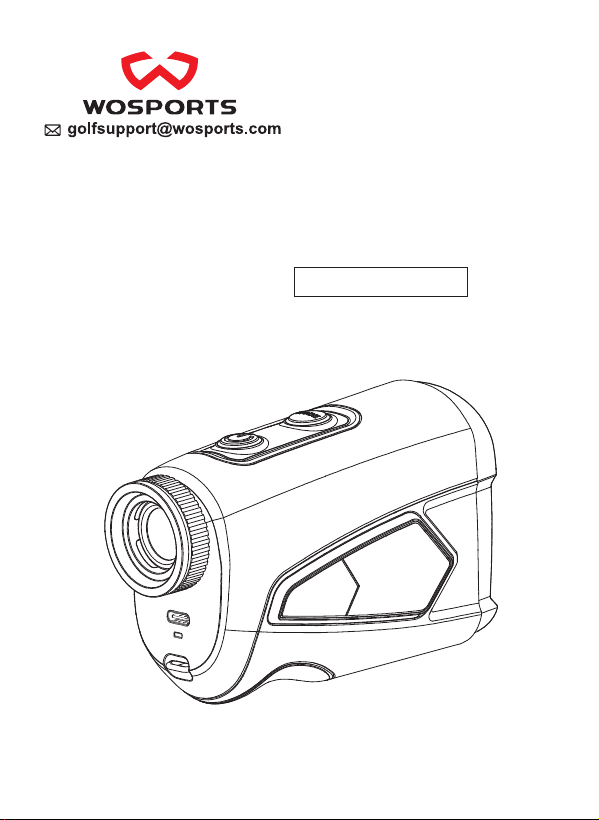
Range Finder User Manual
L-14 1500 Yards


FAQ
How to transfer the distance units Y/M/FT?
1.In the state of power-on, long press the Mode button.
2.Short press the Power button to switch to Y/M/F.
3.Use the Mode button to make your selection.
4.To save, either short press the Power button again or stop the
operation for 5 seconds.
Why doesn't seem to give accurate range?
1. Ensure the rangefinder has enough power before use.
2. Check the unit of measurement (Yards/Meters/Feet) on
your rangefinder.
3. The range is from 5 yards to the maximum distance. It will
not provide data if the target is beyond the minimum or
maximum range.
4. The environmental factor, such as rain, snow, fog, haze,
sunlight angle etc., will affect the accuracy.
Why doesn't this device work?
First, remove the plastic film from the battery and check the '+'
and '-' positions before installing it.
Second, check the battery power on the LCD screen. Low
power may prevent the device from working properly.
Third, the environmental factor, such as rain, snow, fog, haze,
sunlight angle etc., will affect the device.
How to make it clear?
Please turn the eyepiece to adjust the focus and make the view
clear.

Why does it tell the tree is 10 yards from my stand, but
the actual distance is 35 yards?
The distance measurement requires a cone-shaped barrier-free
line. The farther the distance, the larger the diameter. For a
distance measurement of 500 meters, no objects should be
within a 5-meter diameter.

CONTENTS
1. Product Specifications
2. Instruction Consideation
General Index 6
List of Accessories
Part of Device
3. General Operation
Power on/Power off
Slope on/Slope off
Aiming Symbol and Units Selection
LCD Display Description
Measurement Considerations
Battery Instructions
4. Model Operating Instructions
5. Using Scene Description
General Using Scene Description
Golf Slope Correction Using Scene Description
6
7
8
11
11
11
Single Measurement /Continuous Measurement /Failure
12
15
13
15
6. Safety Precautions
Transport/Storage/Maintenance/Disposal Transport
17
9
10
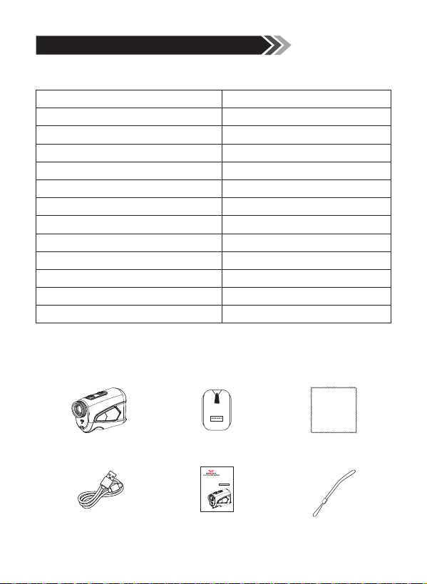
1. Product Specifications
800mAh
120*40*70mm
170g
5-1500(Y)
±1Y
-60° - 60°
-10°C - 50°C
±1°
22mm
3.7mm
7X
905nm(Class I)
7.5°
Battery
Dimensions
Weight
Range
Range Measuring Accuracy
Angle Measuring Range
Operating Temperature
Angle Measuring Accuracy
Object Lens Size
Exit Pupil Diameter
Magnification
Laser type
Field Angle
1.1 General Index
1.2 List of Accessories
Rangefinder
USB Cable
Carry Bag
User Manual
Lens Cloth
Range Finder User Manual
L-14 1500 Yards
Hang String
6
1
2
3
4
5
9
6
7
8
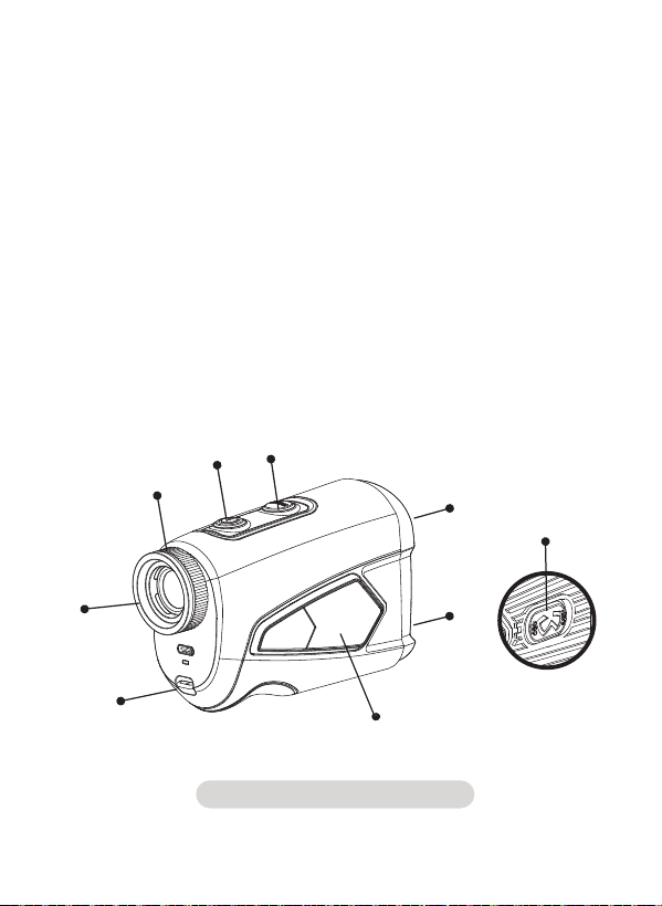
Figure 1 Parts of device
1. Receiving Lens
2. Emitter / Objective Lens
3. Mode / Distance / Units Selection
4. Power Start Button
5. Focusing Ring
6. Eyepiece
7. Lanyard Anchor
8. Magnetic Iron
9. Slope on/off Switch
1.3 Parts of Device
7
5
6
7
8
9
10
11
4
3
2
1
Note:
The full LCD only shows when turn on. Some icons will not
display while using.
LCD screen uses the most advanced technology, but this does
not ensure completely removal of dust. When using this
product, the LCD screen will be inhigh magnification and dust
may appear in the form of defects, but does not affect
ranging function.
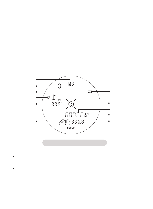
Figure 2 LCD Display
1.4 LCD Display Description
1.
2.
3.
4.
5.
6.
Battery Indicator
Target
Range Data
Meter / Yard / Feet
Vertical / Horizontal /
Slope Compensation Distance
Slope Distance Symbol
7.
8.
9.
10.
11.
Angle
Vibration
Flag Lock
Bow Hunting
Model
8
Golf Flag
Building’s Wall
Trees Utility Pole Animals
2. Instructions Considerations
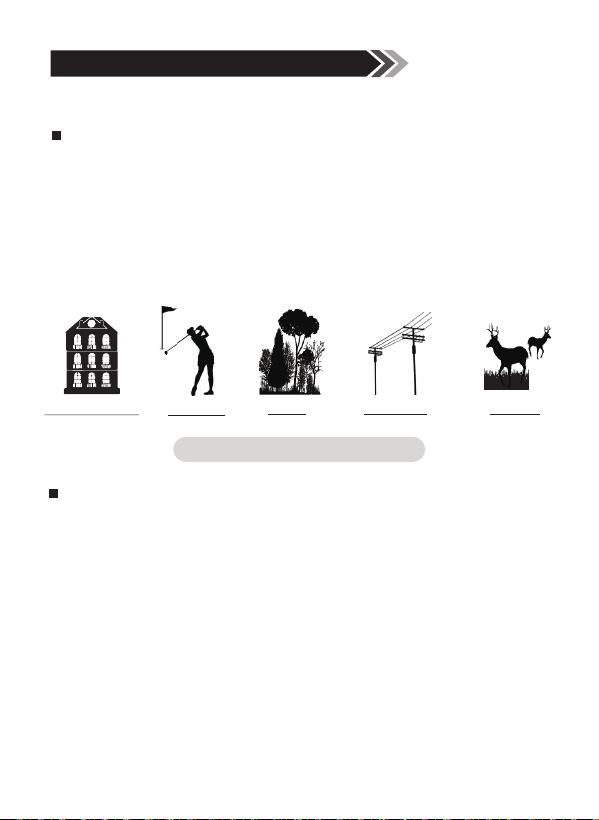
The range finder is suitable for measuring high reflectivity
objects(such as highway's signpad), moderate reflectivity
objects(such as building's wall)and low reflectivity objects
(such as tree, golf flag, utility pole, animal etc.)When the
reflectance is reduced to a certain extent, the range will be
reduced accordingly.
Measurement targets
2.1 Measurement Considerations
Figure 3 Measurement targets
Factors that influence ranging capability
1) Target reflectivity: Generally speaking, the higher the
reflectivity of the object, the better the ranging ability.(It may be
fail to measure the target that can hardly create diffuse
reflection, such as water surface.)
2) Target shape: When a target is too small or uneven, ranging
capability and range corresponding speed will decrease.
3) Measuring angle: The ranging ability would be better if the
measured object is vertical with laser emission's direction. It's
possible that the measuring range cannot meet the ranging
ability specified in the manual under some extreme conditions.
9
4) Environment factor: The environment factors including
sunshine intensity, the concentration of water vapor in the air
and suspended particles.(such as rain fog, snow, fog, haze,
etc.)
The range ability of the product defined under the
following conditions:
1)The measurement target is with moderate reflectivity, such
as building walls.
2)The measured object is vertical with laser emission
direction.
3)The weather condition is sunny but not direct sunlight.
Full power:
2.2 Battery Instructions
Power indication
Charging
Low battery, please charge:
1. Please use DC 5V adaptor to charge.
2. Green light will light when succesesfully connected whit the
power. Red light will light while charging with USB cable, and it
will turn off when fully charged.
When icon " " flashes, the battery is low and should be
recharged immediately to avoid inaccuracy or non-working.
10
3. General Operation
3.1 Power on/Power off
Power on: in the state of power-off, press the power button
for more than 2 seconds and all the signs will show on the
LCD screen. lf only short press the power button, the LCD
screen just displays last used or default mode signs, not all
signs.
Power off: The product will shut down automatically in 8
seconds if with no operations.
3.2 Slope on/Slope off
When the slope switch shows red, it will close the slope
compensation function to meet the regulations of golf
championships. When the slope switch shows black, the
slope is open and it can be ready for the amateur use and
training.
3.3 Aiming Symbol and Units Selection
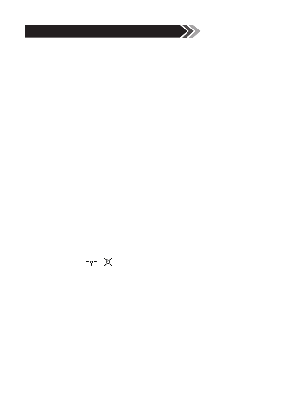
In the state of power-on, long press the Mode button, SETUP
will appear, and / will flash. Short press Mode button to
select the aiming symbol.
Short press the Power button again, and Y/M/FT will flash.
Then short press the Mode button to choose units, Y/M/FT.
Short press the power button again or stop the operation for
5 seconds, it will save and exit setting.
11
3.4 Single Measurement /Continuous Measurement /
Failure
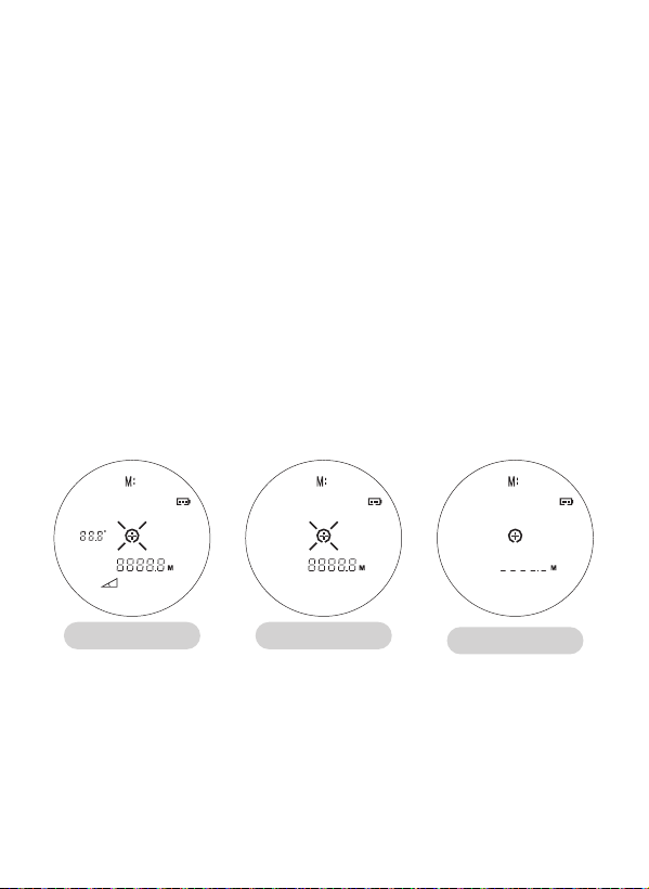
Single measurement: Short press the power button to start
single measurement
Continuous measurement: Press the power button and keep
over 2 seconds. the measured distance value displays
alternately on the LCD screen, and the target sign + will show
on the screen until release the power button.
Failure measurement: Failure Measurement shows like figure
6. The product will shut down automatically in 8 seconds if
with no any operations. Press the power button again and it
will start on.
Note: lf the measure fails, the measured value on the screen
will display as:"--"
Continuous
Measurement
Single
Measurement
Failure
Measurement
Figure 4 Figure 5
Figure 6
12
4. Model Operating Instructions
4.1 L-14
Mode Icon
The model is a function-enhanced models for golf sports, with
Range/Angle/Flag locking/Slope distance correction/Horizon-
tal/Vertical distance.
Figure 7 Figure 8
Figure 10Figure 9
Single measurement
Slope on
Slope off Hunting mode
13

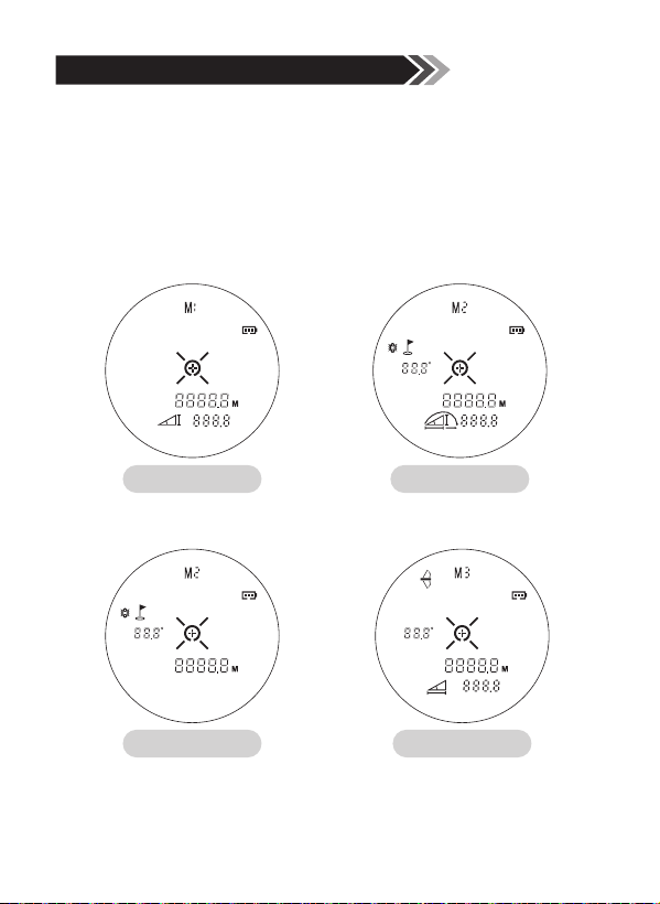
M1 mode, short press the power button after targeting,
vertical and straight-line distance will display on the
screen.(as figure 7)
M2 mode with slope on, aim at the flag or other targets,
short press power button, the flag sign stops flashing, and
the machine vibrates. Angle, range data of the flag and the
compensation distance show on the screen.(as figure 8)
M2 mode with slope off, only angle and range data of the
flag show on the screen.(as figure 9)
1)
M3 mode with bow hunting, aim at the target, and short
press power button, it will professionally show the angle,
straight-line and horizontal distance.(as figure 10)
3)
2)
Mode Description
14
5.2 Golf Slope Correction Using Scene Description
5. Using Scene Description
Figure 11
5.1 General Using Scene Description
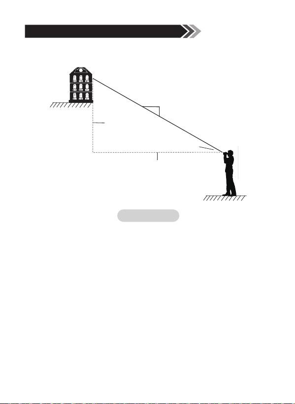
SD/Angle/HD/VD
SD(slope distance)
Angle
HD
(horizontal distance)
VD
(vertical distance)
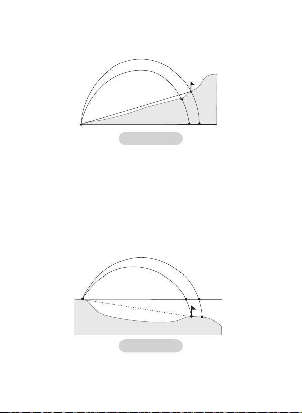
Golf model built in high-precision angle sensor, while during the
measuring process, it will calculate the driving distance
(compensation distance) by Golf trajectory eguation with
distance AB and the angle.
In the positive slope, the compensation distance is further than
real distance. See figure 12, AB=AD. According to the actual
distance, hitting like parabola 1, the real drop point is E. But in
the positive slope, you should hit like parabola 2, it will drop in
B point. And the compensation distance is AC.
15
1
A
E
D
C
B
2
1
2
A
C
B E
D
Figure 12
Figure 13
In the negative slope, the compenstation distance is shorter
than real distance. See figure 13, AB=AD. According to the
actual distance, hitting like parabola 1, the real drop point is E.
But in the negative slope, you should hit like parabola 2, it will
drop in B point. And the compensation distance is AC.
The driving diagram of positive slope
The driving diagram of negative slope
16
6. Safety Precautions
6.1 Transport/Storage/Maintenance/Disposal Transport
Please add enough cushioning material in the box to avoid
damaging the machine while in transport. When the machine
falls on the ground, and makes a strange noise, please remove
the battery immediately and stop using.
This equipment has been tested and found to comply with the
limits for a Class B digital device, pursuant to Part 15 of the
FCC Rules. These limits are designed to provide reasonable
protection against harmful interference in a residential
installation.
This equipment generates, uses and can radiate radio
frequency energy and, if not installed and used in accordance
with the instructions, may cause harmful interference to radio
communications.
Storage: Please keep the product out of reach of children.
Don't put it on a high and unsteady place to prevent falling on
the ground. Do not place the product in a high temperature
environment or it may cause damage of the products.
Maintenance: If the product is used in rapidly changing
temperature, The lens surface will covered by fog. So please
don't use it before the fog evaporates. Please clean with lens
cloth but not your hands when it is dirty, or it may cause
damage to the glass coating.
Disposal: The product package and discarded products should
be recycled or disposed properly in accordance with local
laws.
17
However, there is no guarantee that interference will not occur
in a particular installation. If this equipment does cause
harmful interference to radio or television reception, which can
be determined by turning the equipment off and on, the user is
encouraged to try to correct the interference by one or more of
the following measures:
Reorient or relocate the receiving antenna.
Increase the separation between the equipment and receiver.
Connect the equipment into an outlet on a circuit different
from that to which the receiver is connected.
Consult the dealeror an experienced radio/TV technician for
help. Shielded interface cable must be used with the
equipment in order to comply with the limits for a digital
device pursuant to Subpart B of Part 15 of FCC Rules.
Specifications and designs are subject to change without any
notice or obligation on the part of the manufacturer.
18