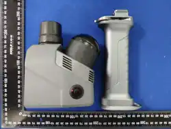
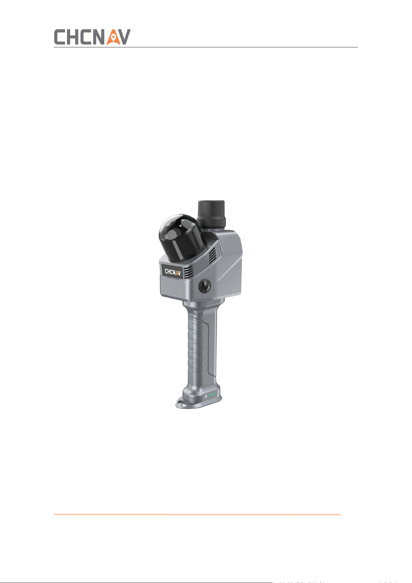
CHCNAV RS7
User Manual
SLAM Solution | February. 2026

2
Table of Content
1 Reading Tips ........................................................................................................................4
1.1 Symbols ....................................................................................................................4
1.2 Service and Support .................................................................................................4
1.3 Safety Guidelines ..................................................................................................... 4
1.3.1 Laser Safety Class ..........................................................................................4
1.3.2 Device Drop...................................................................................................5
1.3.3 Power Supply ................................................................................................ 5
1.3.4 Transportation and Vibration ........................................................................5
1.3.5 Battery Safety................................................................................................5
1.3.6 Chemistry......................................................................................................5
1.3.7 Surface High Temperature............................................................................ 5
1.3.8 Use of Equipment......................................................................................... 6
2 Introduction........................................................................................................................ 7
2.1 Check List................................................................................................................. 7
2.2 Equipment Specifications, Dimensions and Interface............................................. 9
2.3 Product Parameters............................................................................................... 10
3 Product Usage ...................................................................................................................12
3.1 Work .......................................................................................................................12
3.1.1 Battery Charge ............................................................................................ 12
3.1.2 Equipment Installation ................................................................................13
3.1.3 Mobile Phone Bracket Installation ..............................................................13
3.1.4 Software......................................................................................................14
3.2 Data Acquisition .....................................................................................................15
3.2.1 Equipment Start-up .....................................................................................15
3.2.2 Device Connection ...................................................................................... 15
3.2.3 Device Diagnostics ...................................................................................... 17
3.2.4 Project Management .................................................................................. 18
3.2.5 Log Upload .................................................................................................. 18
3.2.6 Infrastructure ..............................................................................................19
3.2.7 RTK Settings ................................................................................................ 19

3
3.2.8 Other Settings ............................................................................................. 20
3.2.9 Start Collecting ............................................................................................21
3.2.10 One-click Collection .................................................................................. 24
4 Collection Guide ................................................................................................................26
4.1 Route Planning .......................................................................................................26
4.2 Loop Requirement ................................................................................................. 26
4.3 Precautions for Data Acquisition ........................................................................... 26
5 Data Processing .................................................................................................................28
5.1 Data ........................................................................................................................28
5.1.1 Data Copying ...............................................................................................28
5.1.2 File Structure...............................................................................................29
5.1.3 Data Cleaning ..............................................................................................29
5.2 Software Installation ..............................................................................................29
5.2.1 Install ...........................................................................................................29
5.2.2 Software Registration ................................................................................. 30
5.3 Data Resolution ......................................................................................................31
5.3.1 New Construction ....................................................................................... 31
5.3.2 Coordinate System Setup ............................................................................32
5.3.3 Real-time Point Cloud Loading ....................................................................34
5.3.4 One-click Refinement ..................................................................................35
5.3.5 Results Browsing.........................................................................................44
5.4 Point Cloud Display ................................................................................................ 44
5.5 Export Results ........................................................................................................ 45
6 Frequently Asked Problems and Solutions ....................................................................... 46
6.1 RS7 Host ................................................................................................................. 46
6.2 SmartGo ................................................................................................................. 46
7 Daily Use and Precautions ................................................................................................ 47
7.1 Use ......................................................................................................................... 47
7.2 Daily Service Specification ..................................................................................... 47
7.3 Equipment Transportation .....................................................................................48
7.4 Equipment Storage ................................................................................................ 48
4
1 Reading Tips
1.1 Symbols
Forbid
Warning
Important note
Operate & Using tips
1.2 Service and Support
For assistance, please first consult this manual, our website www.chcnav.com, or your
local CHCNAV dealer. If your issue remains unresolved, you can contact our technical
support team directly at support@chcnav.com.
1.3 Safety Guidelines
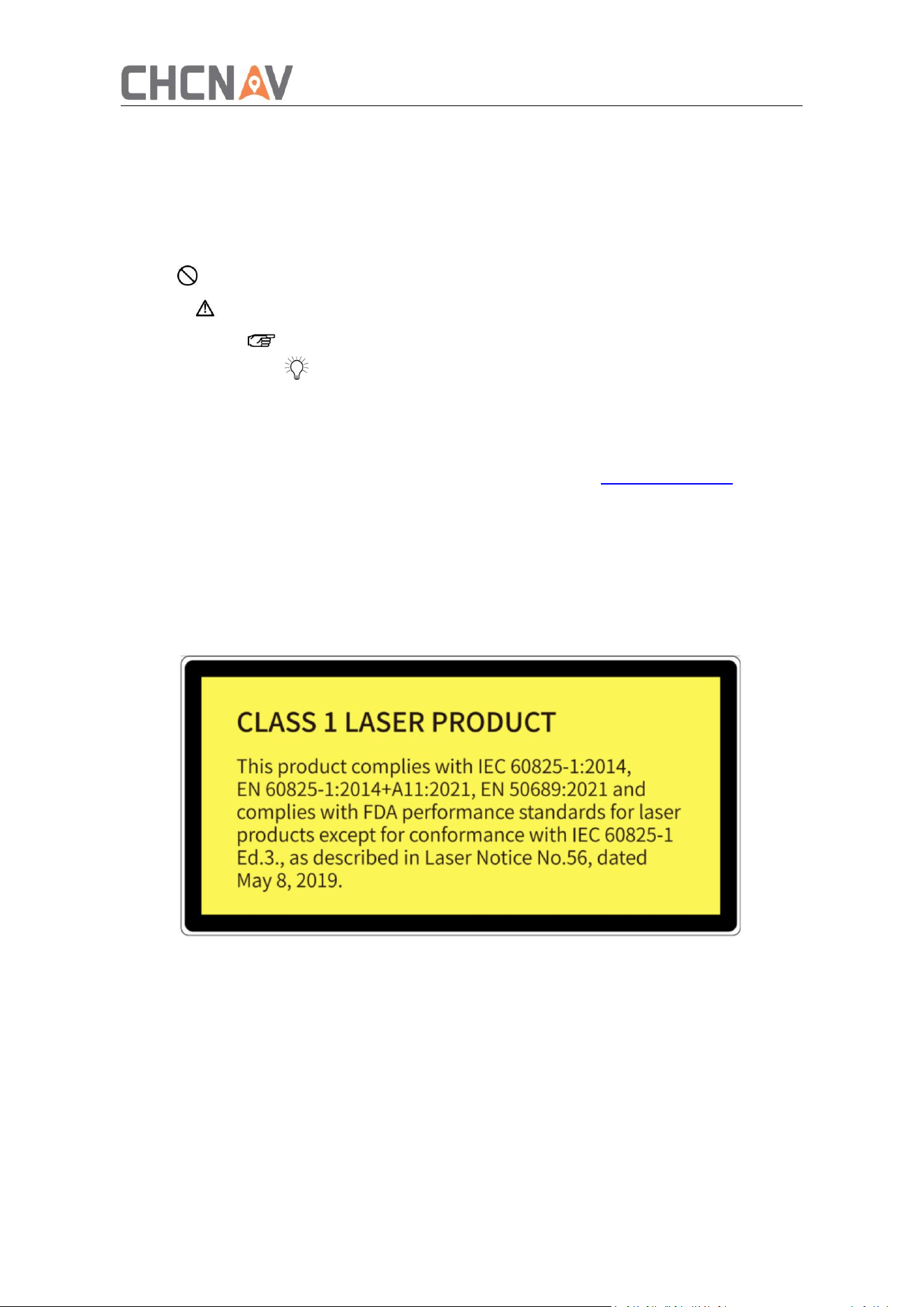
1.3.1 Laser Safety Class

5
1.3.2 Device Drop
This product contains precision electronic components.
Dropping, crushing, puncturing, or improper handling may cause permanent damage.
If the device is dropped, stop using it immediately and contact CHCNAV after-sales
support for assistance.
1.3.3 Power Supply
Ensure the power interface is dry and free of debris before powering on.
Only use power cables and adapters provided or approved by CHCNAV.
Do not use damaged power cables or adapters that do not meet the specified power
requirements.
1.3.4 Transportation and Vibration
Avoid strong vibration and mechanical shock to prevent damage to the device.
Mechanical shock or vibration exceeding the allowable range may damage the
product.
CHCNAV is not responsible for equipment damage caused by improper logistics
handling during transportation.
For detailed shock and vibration specifications, please contact CHCNAV technical support.
1.3.5 Battery Safety
Do not immerse the battery in water. Store it in a cool, dry place when not in use.
Keep the battery away from heat sources during both use and storage.
Avoid short circuits by keeping battery terminals away from metal objects.
Do not tap, drop, or step on the battery.
Do not weld or puncture the battery with sharp objects.
If the battery will not be used for an extended period, maintain its charge level
between 30% and 50%. Fully charge and discharge the battery at least once every
three months.
After around 500 charge cycles, battery capacity may decrease to approximately 80% of
the original capacity.
1.3.6 Chemistry
Do not expose the product to corrosive or highly reactive chemicals (liquids or gases),
including but not limited to strong acids, strong bases, esters, or ethers. Such exposure
may cause damage, including the loss of waterproof protection.
1.3.7 Surface High Temperature
During operation and for a period after use, the device surface may become hot.
Avoid direct skin contact with the product shell to prevent burns.
Keep flammable materials away from the device to reduce the risk of fire.

6
1.3.8 Use of Equipment
Use and maintain the device in accordance with this user manual. Damage, reduced
service life, or malfunction resulting from improper use, improper maintenance, or
unauthorized disassembly is not covered by warranty. All related repair and maintenance
services will be charged according to standard service fees.
7
2 Introduction
The RS7 is a tool-level entry-level handheld SLAM 3D scanning product launched by
CHCNAV, delivering uncompromising performance. It adopts deep integration of
high-precision inertial navigation and SLAM technology, incorporating a high-frequency
ultra-wide-angle LiDAR for full-grid online scanning details and a 48MP high-definition
camera for pixel-level reproduction of scanned scenes. The device features fully open
hardware interfaces and SDKs, and together with CoCloud, builds a cloud-integrated data
processing workflow. Focused on full-scenario adaptability with a minimalist operation
process, the RS7 is primarily used in fields such as architectural surveying, interior design,
decoration and renovation, and underground space measurement. It provides a
cost-effective 3D data acquisition entry-level solution that reduces costs and increases
efficiency.
2.1 Check List
Note: Please refer to the actual delivery list.
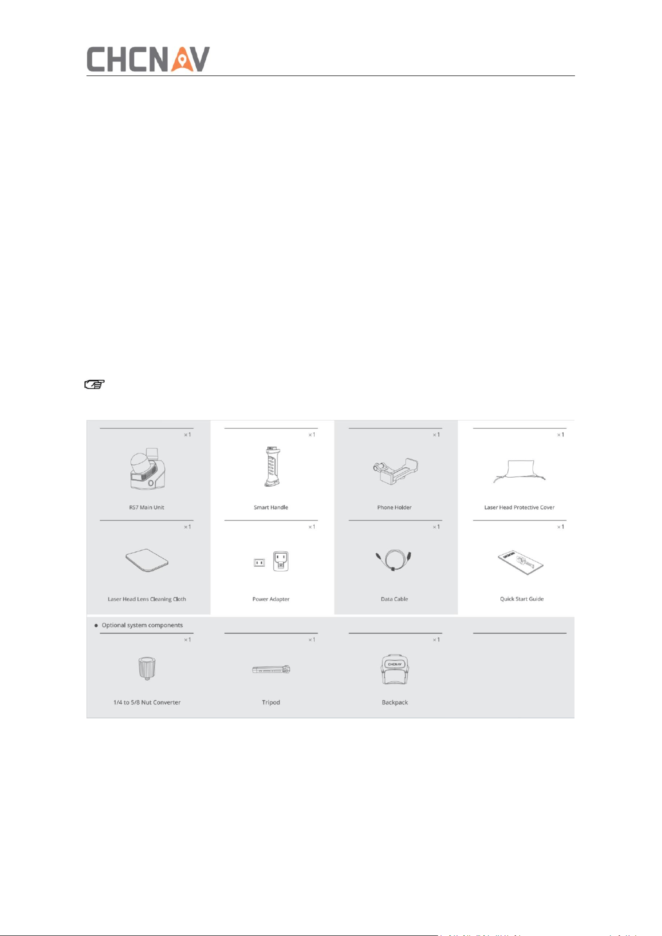
RS7 Surveying System configuration list is shown below:

8
N
Description
Pcs
Type
1
RS7 unit
1
Standard
2
Smart Handle
1
Standard
3
Phone Holder
1
Standard
4
Laser Head Protective Cover
1
Standard
5
Laser Head Lens Cleaning Cloth
1
Standard
6
Power Adapter
1
Standard
7
Data Cable
1
Standard
8
Quick Start Guide
1
Standard
9
1/4 to 5/8 nut converter
1
Optional
10
Tripod
1
Optional
9
2.2 Equipment Specifications, Dimensions and Interface
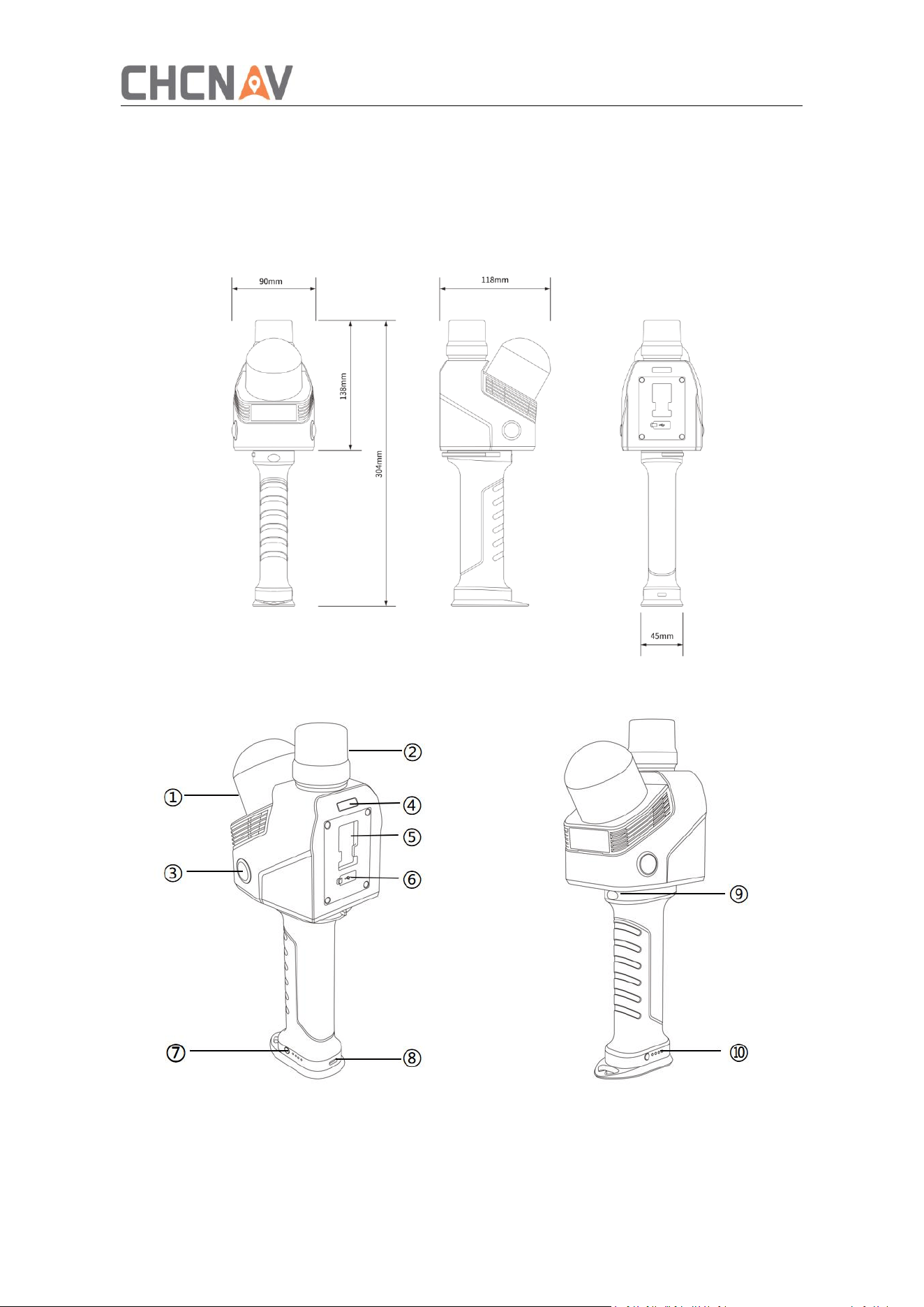
The weight of the equipment is about 1.2 kg.
The length, width and height (118 × 90 × 304 mm) are as follows:
Interfaces and Indicators

10
①
LiDAR
⑥
Data transmission interface
② RTK antenna ⑦ Handle battery button
③ Camera ⑧ Charging port
④
Unit status indicator
⑨
Function button
⑤ Handset bracket interface ⑩ Handle battery indicator
2.3 Product Parameters
System
parameter
Absolute accuracy
Horizontal: < 3cm RMS ①
Vertical: < 3cm RMS
①
Relative accuracy
<1cm②
Repetition accuracy
<2cm②
Power supply
Battery Handle
Battery capacity
47.5wh
Single cell operating time
About 150 minutes ③
Power consumption
16W
Waterproof and
dustproof grade
IP64④
Storage capacity
512G
Operating temperature
-20~50
℃
Weight
1.2kg (including handle battery)
Laser
parameters
Field of view
360°*189°
Laser safety class
Class1
Ranging
40m (10% reflectivity)

11
Point frequency
1152000 points/sec
Number of laser
channels
64
Wavelength
905nm
Echo
2
Position and
pose system
Satellite system
GPS:L1, L2, L5
GLONASS:L1, L2,
Galileo
:
E1, E5a, E5b
BeiDou
:
B1,B2,B3
QZSS
:
L1C/A, L1C, L2C, L5, L6
IMU
UPDATE
500Hz
Gyroscope bias instability
0.5°/hr
Gyroscope random walk
0.01
°
/
√
hr
Accelerometer bias
instability
10ug
Accelerometer random
walk
0.017m/s/√hr
Camera
Quantity
2
Resolution
4800w
Sensor size
1/2 in.
Field of view
340°(H)*360°(V)
① ② Measured at the CHCNAV standard test site. Deviations may occur in certain
scenarios.
③
Measured at room temperature (25 °C) with the equipment at rest.
④ It offers splash-proof, waterproof, and dustproof protection. This protection
performance has been tested and verified in a standard laboratory environment.
According to the IEC 60529 standard, the protection level is rated IP64.
12
3 Product Usage
3.1 Work
3.1.1 Battery Charge
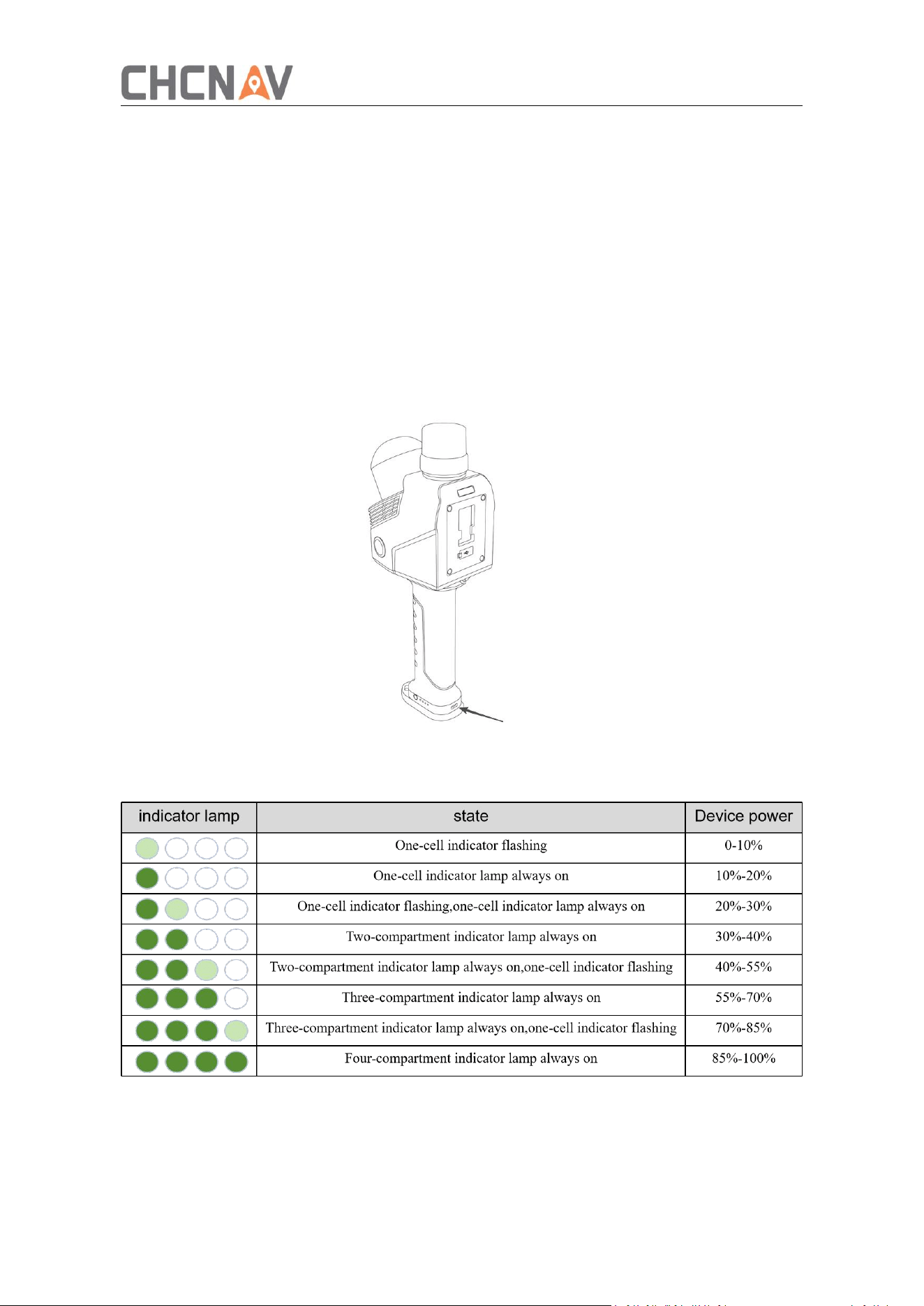
Use the standard power adapter to connect the charging cable to the handle battery.
It takes approximately 2 hours to charge the battery power from 0% to 100%.
Do not connect the charging cable to the Type-C interface of the host, and turn off the
phone to charge.
The device indicator light shows the remaining battery power of the handle, please refer
to the table below for details.
13
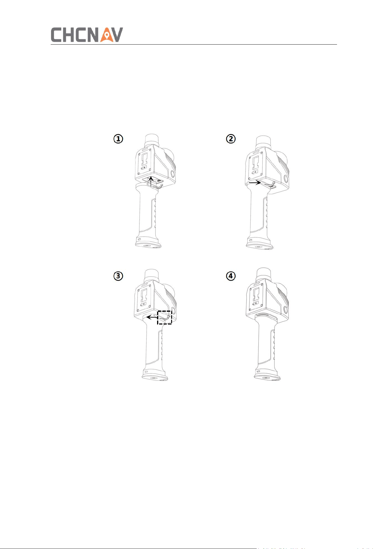
3.1.2 Equipment Installation
Release the handle latch,
Insert the battery handle into the bottom groove of the main unit.
Ensure the battery is securely installed, then lock the handle latch.
Caution: Ensure the handle latch is locked, otherwise it may cause poor battery or device
drop.
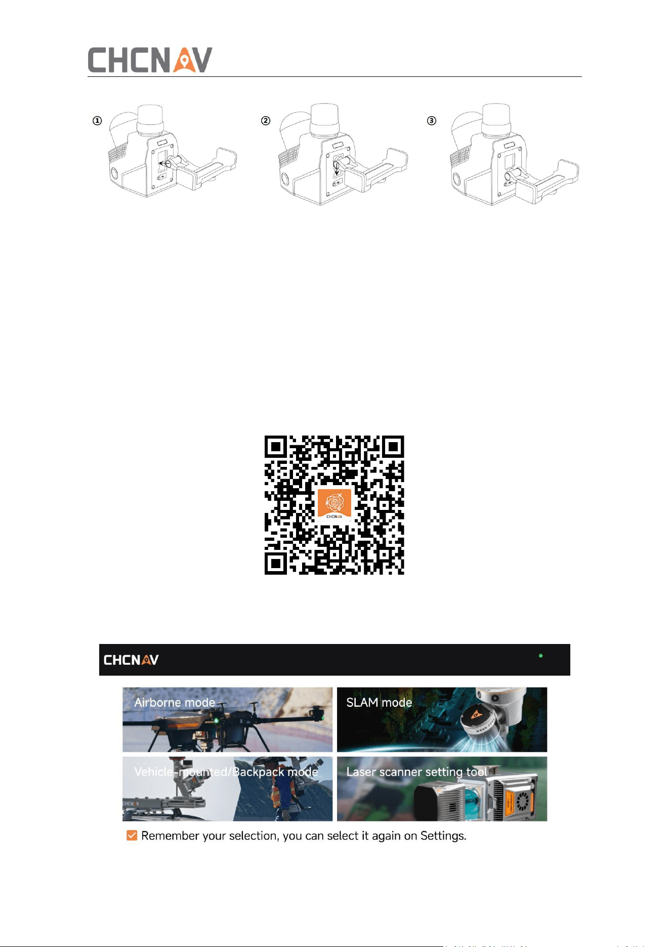
3.1.3 Mobile Phone Bracket Installation
Align the bottom of the mobile phone mount with the mounting interface on the back
of the main unit.
Tighten the mounting knob to secure the bracket.
After the installation is completed, the angle of the bracket can be freely adjusted.
14
3.1.4 Software
The RS7 data acquisition software is SmartGo, a comprehensive application control
software self-developed by CHCNAV. It covers four major modules: airborne,
vehicle-mounted, handheld, and Lidar setting tools, enabling device control and data
acquisition functions. SmartGo provides a full 3D display of routes and terrain, presenting
complex work sites to users more intuitively.
Scan the QR code below or visit the CHCNAV official website at
https://support.chcnav.com/portal/en/kb/articles/smartgo-rs07
to download and install the software. SmartGo currently supports only Android systems.
When launching SmartGo on the mobile phone for the first time, you need to select
the SLAM job. After selection, you can switch the job in the settings in the upper right
corner of the software.
15
3.2 Data Acquisition
3.2.1 Equipment Start-up
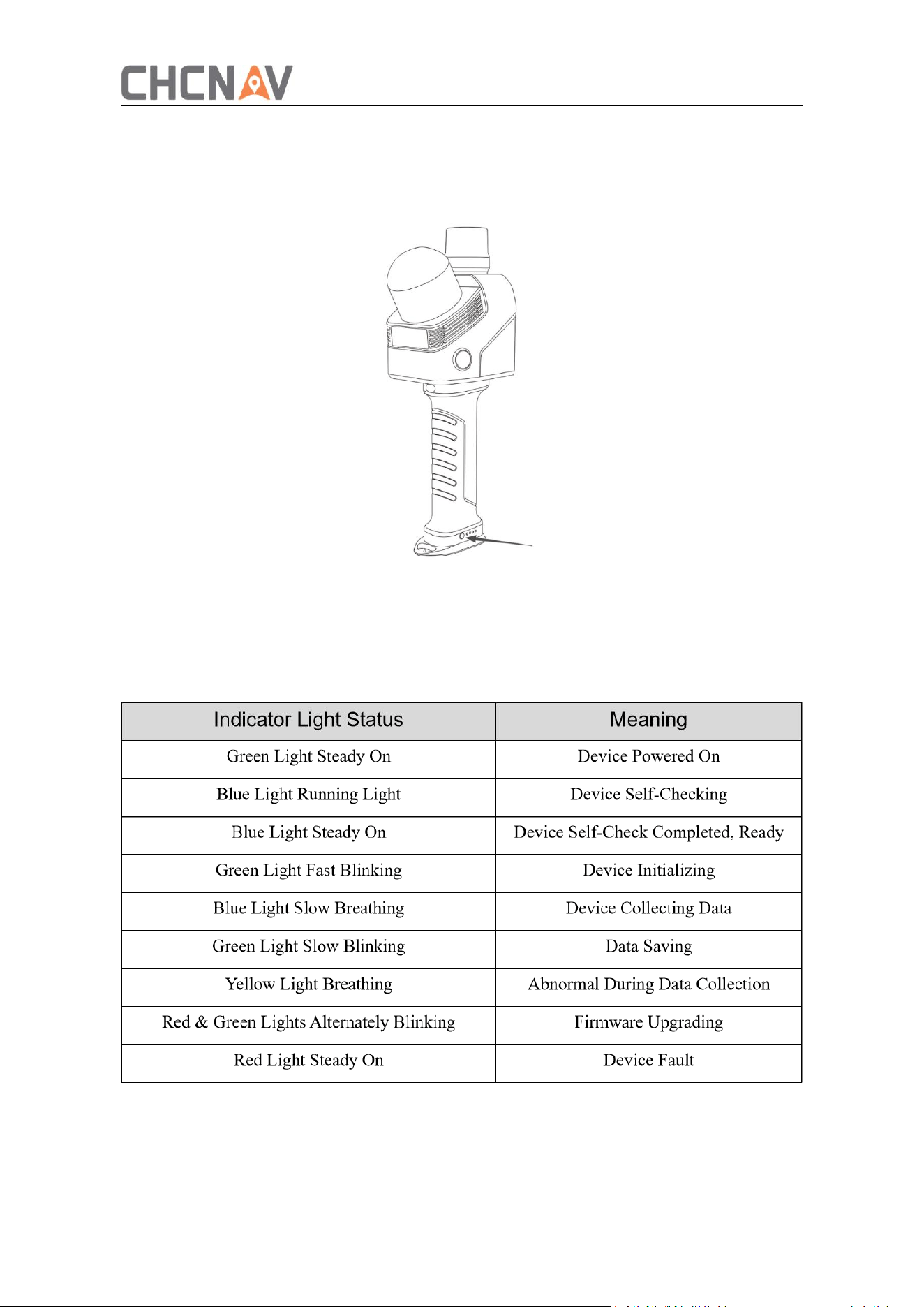
After the handle battery is installed, short-press and long-press the buttons under the
handle for 2 seconds.
When the power indicator lights turn on in turn and the host indicator light is solid
green, the device is turned on.
Main Unit Indicator Status
3.2.2 Device Connection
Open the SmartGo software and select SLAM job, select the device WIFI name
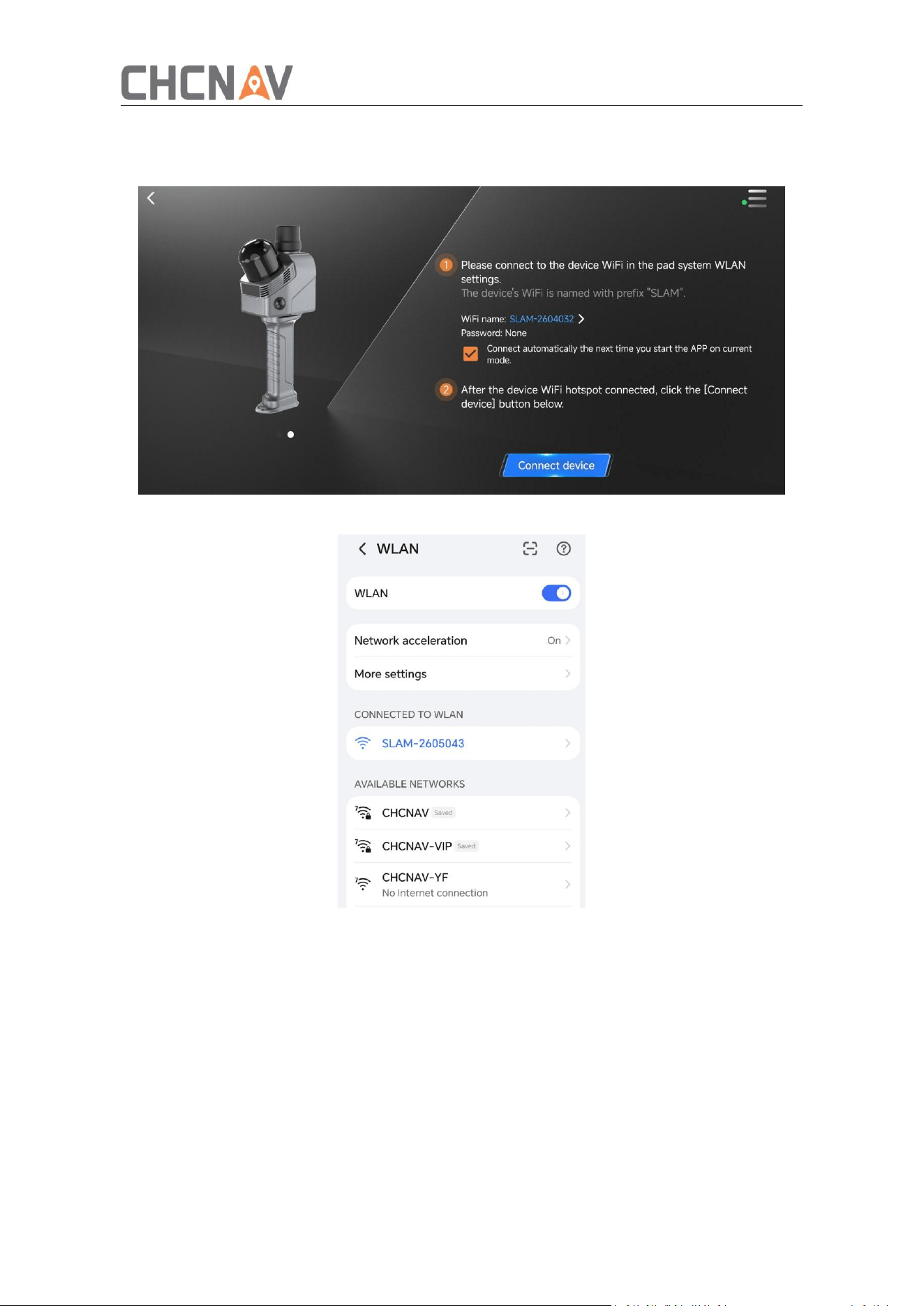
16
starting with SLAM-xxxx on the device connection interface and connect, no password
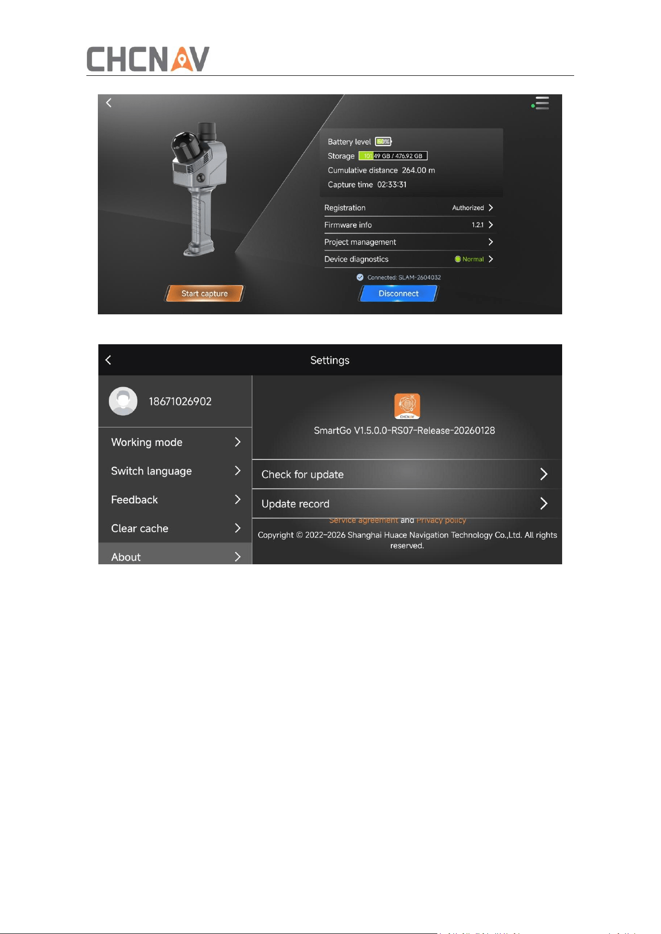
is required.
After connection:
Check device battery level and remaining storage.
Check firmware and software versions.
Confirm device authorization status. If authorization has expired, contact CHCNAV
technical support.
17
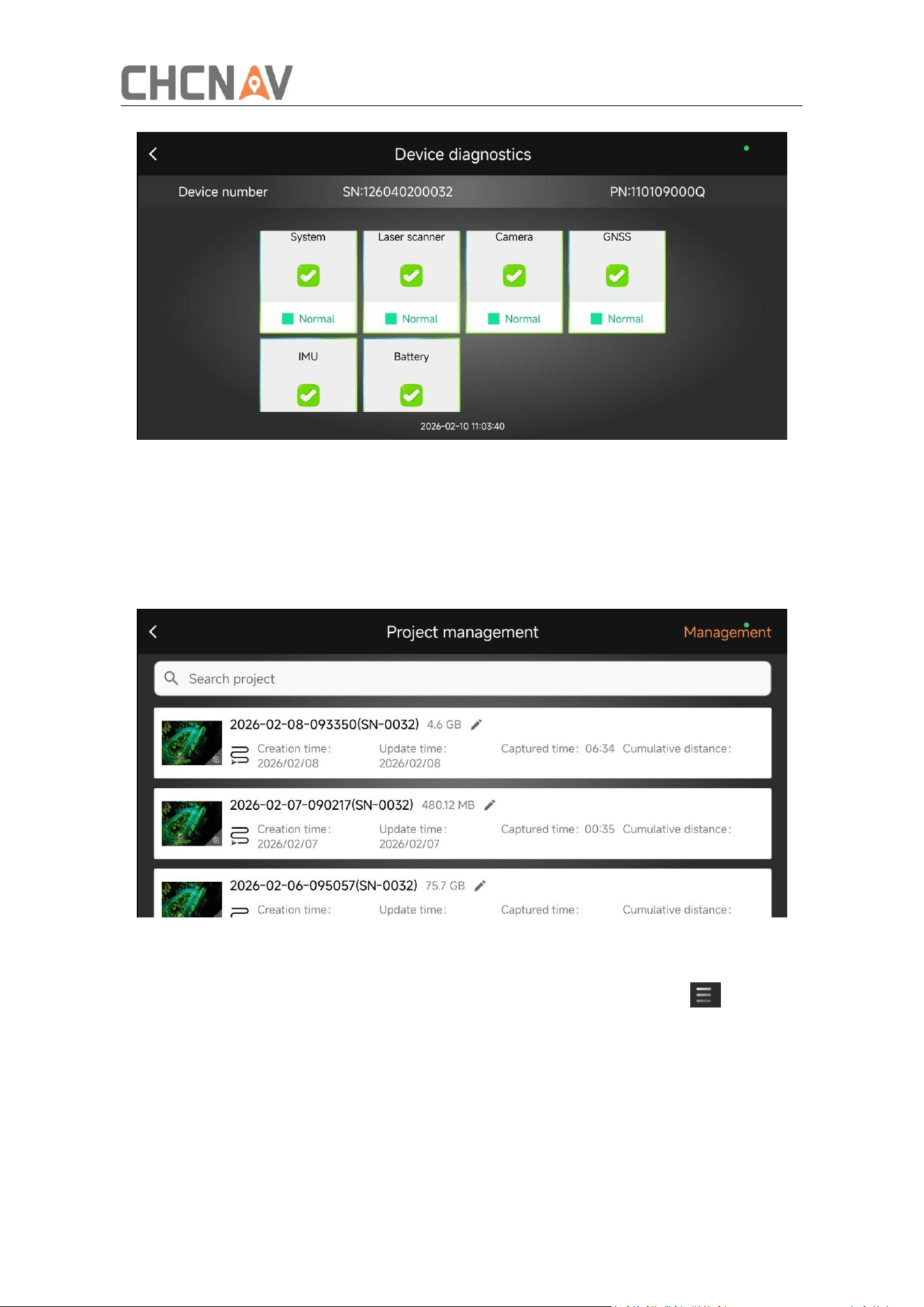
3.2.3 Device Diagnostics
Click device diagnostics to view the status of various sensors of the current device. If
there is any abnormality, restart the device and try to recover. If the restart cannot be
resolved, contact the after-sales personnel of CHCNAV.
18
3.2.4 Project Management
Click on the project management to view historical collected project information,
including project name, real-time point cloud thumbnails, creation time, collection
time, collection mileage, etc.
Click Manage to manually delete historical projects, then the raw data in device will
be synchronized delete too.
3.2.5 Log Upload
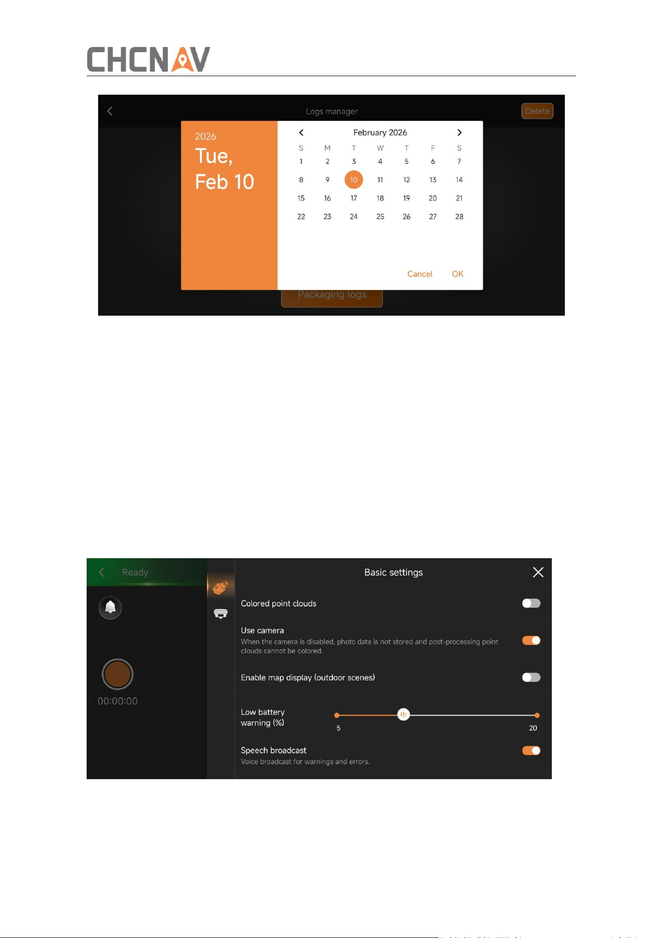
If you encounter problems during the use of the device, you can
upload the log for analysis. When the device is connected, click the
upper right corner of the software to select Log Management and click Package Log.
Select the corresponding date and confirm. The software will automatically package
the current device log.
After clicking Upload, you can Contact CHCNAV after-sales personnel to download.
19
3.2.6 Infrastructure
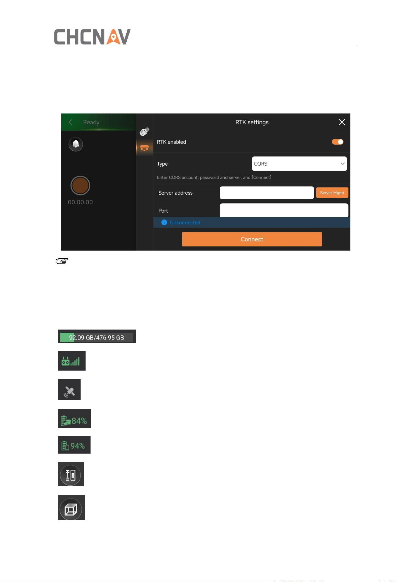
After connecting the device, click ‘Start Capture’ to enter the collection interface, click the
setting button in the upper right corner of the software to enter the basic setting
interface.
Turn on the ‘Colored point clouds’, it will use camera to coloring the point clouds in
real time during the data collection process.
Turn on the ‘Use camera’, and the camera will take photos when the device collecting
data, which can be used to coloring point clouds, build mesh models, etc. The camera
will not work if disable this function.
The low battery reminder percentage can be set. When the set threshold is reached,
SmartGo will actively remind that the battery is too low, please charge in time.
Turn on the broadcast, and the software will broadcast the status information of the
device in real time during the use.
3.2.7 RTK Settings
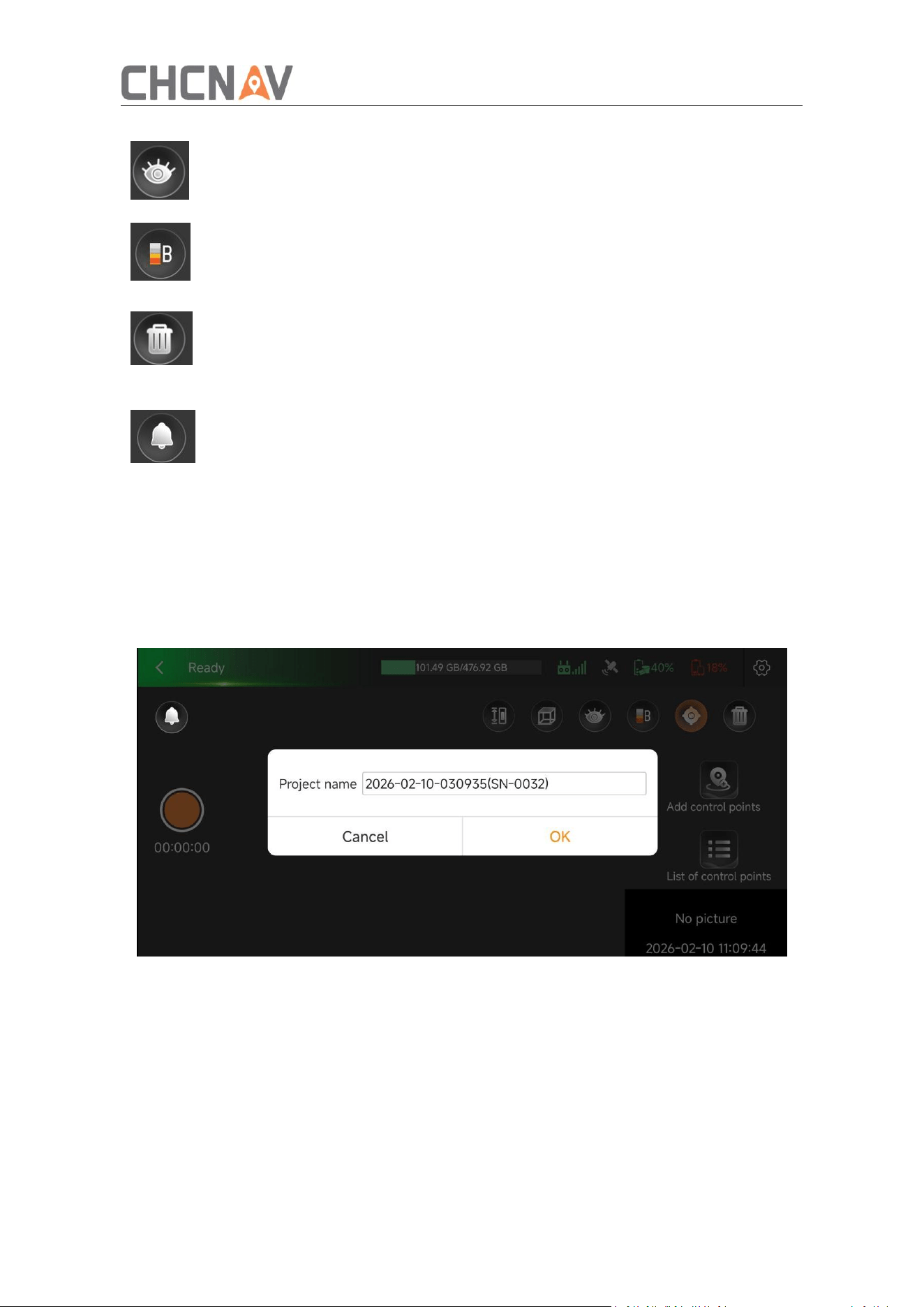
After connected, enter the collection interface, click the setting button in the upper
20
right corner, enter the RTK setting interface, open the CORS account type, enter the
corresponding server address, port, user name and password, obtain the source list,
and click Connect.
The types of CORS accounts currently supported are: one-click fixed, CHCNAV CORS,
CORS, Qianxun CORS, APIS.
Note: Ensure the device is under CORS coverage and the mobile phone has internet
access.
3.2.8 Other Settings
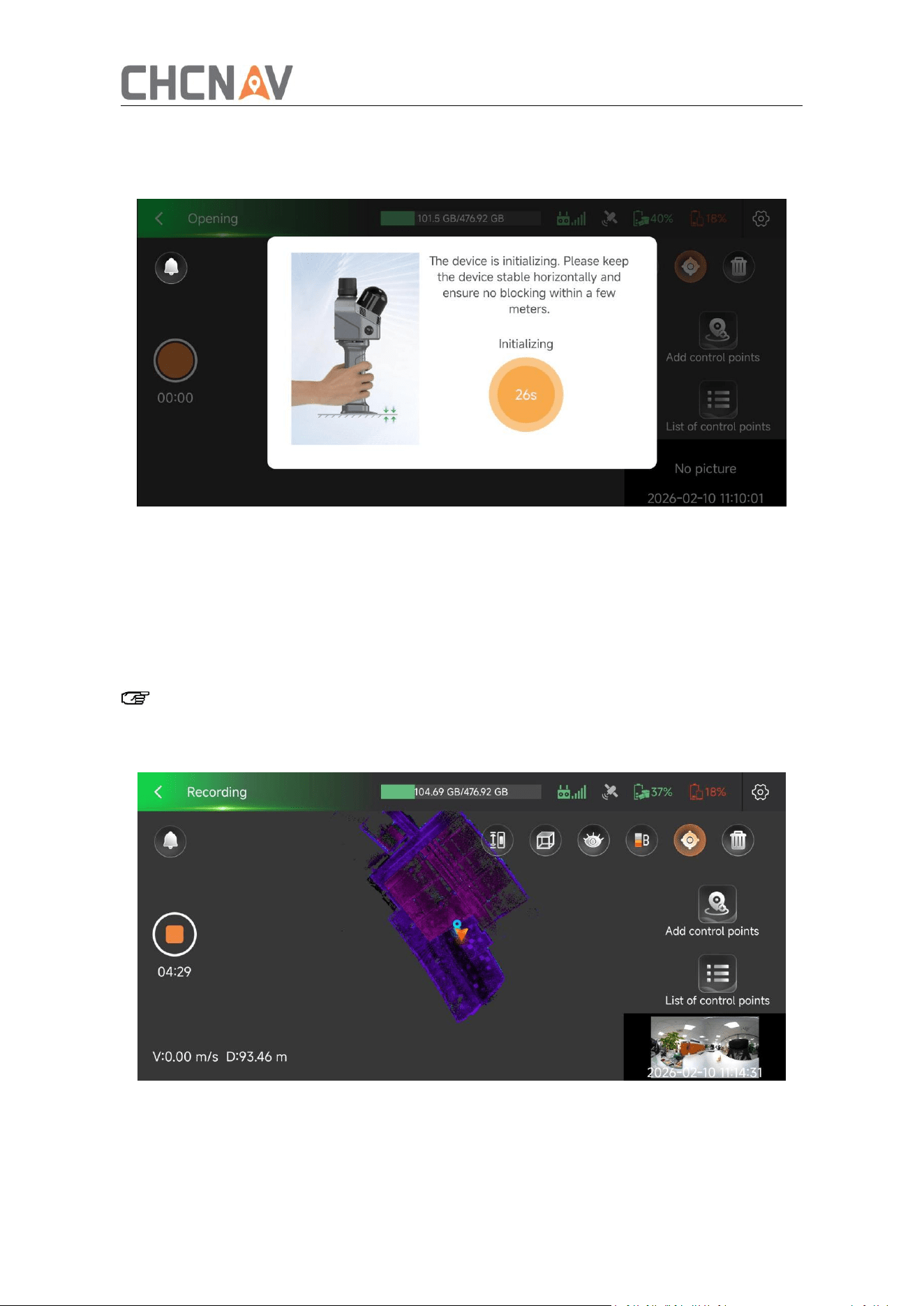
The main interface of the software can display device status information in real time. The
specific information types and explanations are as follows:
Displays memory used and remaining on device
Indicates the connection status of the phone and device
Indicates the satellites search status and number
Indicates the remaining power of the device
Indicates the remaining battery of the phone
Point clouds of different elevation ranges can be displayed
with this setting
Point clouds can be restored to top view state with one click
21
3.2.9 Start Collecting
① Create a project: Ente the acquisition interface, click the orange button on the left side
of the screen to create a new project. The default project name is the collection time and
the last four digits of the device SN. Manual modification of the project name is
supported.
②
Equipment initialization: After the project is created, it needs to be initialized. Refer to
the following initialization precautions:
a. Once the equipment stabilizes, the countdown disappears and initialization is
complete—no need to place it on the ground.
b. During initialization, point the device toward feature-rich objects such as buildings,
irregular rocks, etc., and avoid open or featureless areas.
c. The laser protective cover must be removed during initialization. Avoid pointing the
device at moving objects or manually blocking the laser head.
Can display/hide real-time point cloud information with one
click
Different point cloud renderings, currently supporting
elevation rendering, intensity rendering, mixed rendering and
color rendering
You can clear the real-time point cloud of the SmartGo
interface with one click, this operation will not delete the
collected data inside the device
The current warning and error information of the device will
be displayed, please deal with it according to the displayed
information, if it cannot be resolved, please contact CHCNAV
after-sales service
22
d. Try to avoid highly reflective objects such as glass or mirrors during initialization to
reduce noise.
③
Data collection: Once initialization is complete, data collection can begin according to
the pre-planned walking route. During the process, the SmartGo interface displays the
collection trajectory and real-time point cloud information. Use one finger to drag and
rotate the point cloud, and two fingers to drag and translate it. Throughout the collection,
pay close attention to the real-time point cloud display to ensure complete coverage of
the target area without any missing data.
Note: Real-time point cloud display consumes mobile phone memory. If memory
usage is high, the software will clear the display buffer without deleting original
device data.
④ GCP collection: During data collection, click Add Control Point on the right side of the
interface to collect control points. First, click Add Control Point and enter the name of the
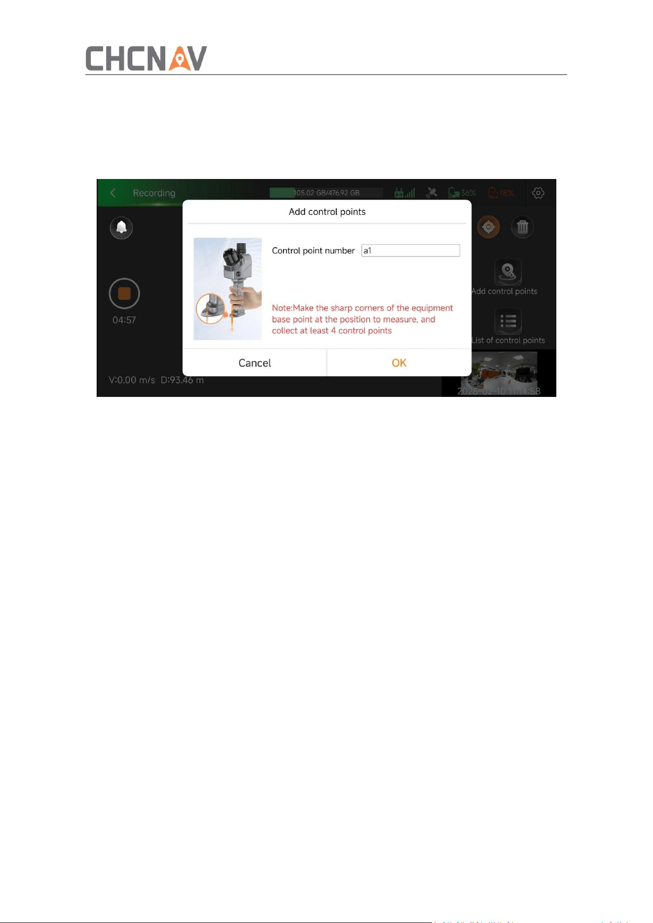
23
control point. Then, align the tip of the device handle with the control point to be
collected. Once stable, click Confirm to complete the control point acquisition.
Click on the Control Points List to view all control points collected in the current project,
and delete selected control points if needed.
Refer to the following precautions when collecting control points:
a. When collecting the control point, squat down and get up smoothly.
b. Avoid people covering the front of the device when the control point is collected.
c. For the same project, at least four control points are required to complete the
coordinate conversion. It is recommended that the control points be evenly
distributed in the survey area and avoid being distributed on a straight line.
d. When collecting control points, there is no requirement for the angle of the
equipment itself, and the acquisition of control points can be completed upright,
horizontal and backward.
e. After the control point is collected, wait 15s before finishing the project.
f. Avoid collecting control points in narrow areas to prevent the laser head from being
obstructed.
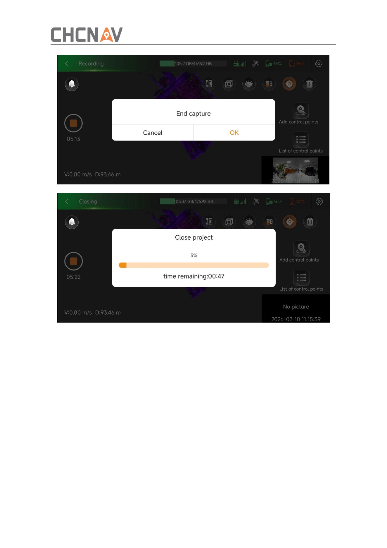
⑤ End collection: After the data scanning is completed, click the orange button on the
left to end the collection, and the device will automatically generate a real-time las point
cloud file of the current project, store it in the original project-SLAM DATA folder, and shut
down after the project is saved.
24
3.2.10 One-click Collection
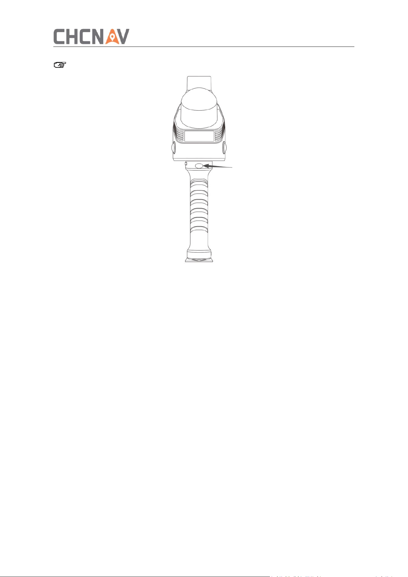
The RS7 supports one-click collection via the button located on the front of the battery
handle.
After the device is powered on, the indicator light stays solid blue, indicating the
device is in standby mode. Press and hold the collection button at the top of the
handle to start initialization. During initialization, ensure the surrounding area is clear
of obstructions and the device remains stable. Once initialization is successful, the
indicator light changes from solid blue to a blue-green breathing effect, indicating the
device has entered scanning mode.
To end data collection, press and hold the collection button at the top of the handle
again. The indicator light will change from blue-green breathing to slow-flashing
green, indicating the device is saving data. When the light changes from slow-flashing
green back to solid blue, the device has finished saving and has returned to standby
mode.
25
Note: One-click collection cannot log in to the CORS account.

26
4 Collection Guide
4.1 Route Planning
Before data collection, plan the survey route in advance to ensure optimal scanning
results. The fundamental principle of route planning is ‘global first, then local.’ Proper
route planning maximizes the effectiveness of the device’s correction algorithms and
enhances overall data accuracy.
Global coverage: Traverse the entire survey area using the shortest possible route to
establish a stable positioning map.
Local refinement: Perform detailed scanning using small loop closures. Progress
incrementally to ensure complete coverage of the survey area.
4.2 Loop Requirement
When GNSS signals are unavailable, loop closure is required to maintain positioning
accuracy. Loop closure is an important method for improving data precision. The
collection route should form closed loops whenever possible.
Ensure loop overlap is greater than 10%.
In complex environments, close loops end-to-end and return along the same path if
necessary.
4.3 Precautions for Data Acquisition
RS7 is a precision instrument. It is forbidden to bump or use the surface of the lidar by
hand during use. Before data collection, ensure that the surface of the laser head and
camera is clean and free of dirt.
In the process of data collection, avoid fast and large-scale turning and shaking, so as
not to affect the accuracy of mapping and the effect of point cloud.
In the process of data acquisition, try to distance more than 0.5 m from the measured
object to achieve good scanning effect.
When collecting data, it is recommended to control the collection speed at 3-5km/h,
and slow down the walking speed appropriately for scenes that require careful
scanning or have few features.
Try to avoid moving pedestrians or vehicles during data collection. If conditions
permit, when encountering numerous moving objects, you may stand still sideways
and resume scanning after the moving objects have passed.

27
During scanning, avoid prolonged blocking of the device by pedestrians. When
multiple personnel are working together, the operator should walk at the front.
During data collection, point the device toward the survey area and monitor the
real-time point cloud display throughout the process to avoid missing data.
When scanning indoor rooms, it is recommended to open all room doors in advance
and enter/exit sideways to ensure a good connection between indoor and outdoor
data. If you cannot open the door in advance, turn around when you are close to the
door, turn the instrument away from the door, open the door with your back and
enter.
28
5 Data Processing
5.1 Data
5.1.1 Data Copying
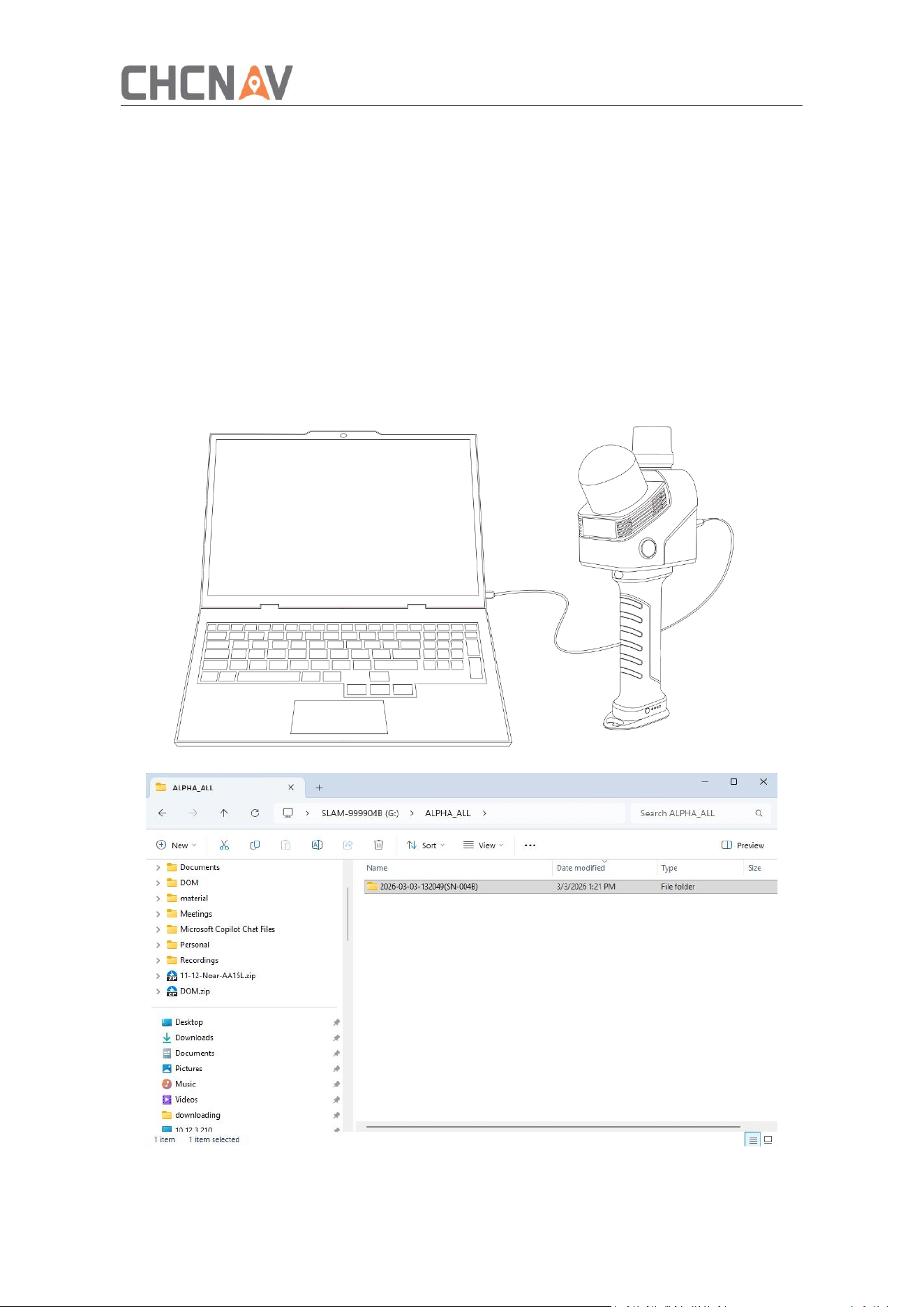
Power off the device before copying data.
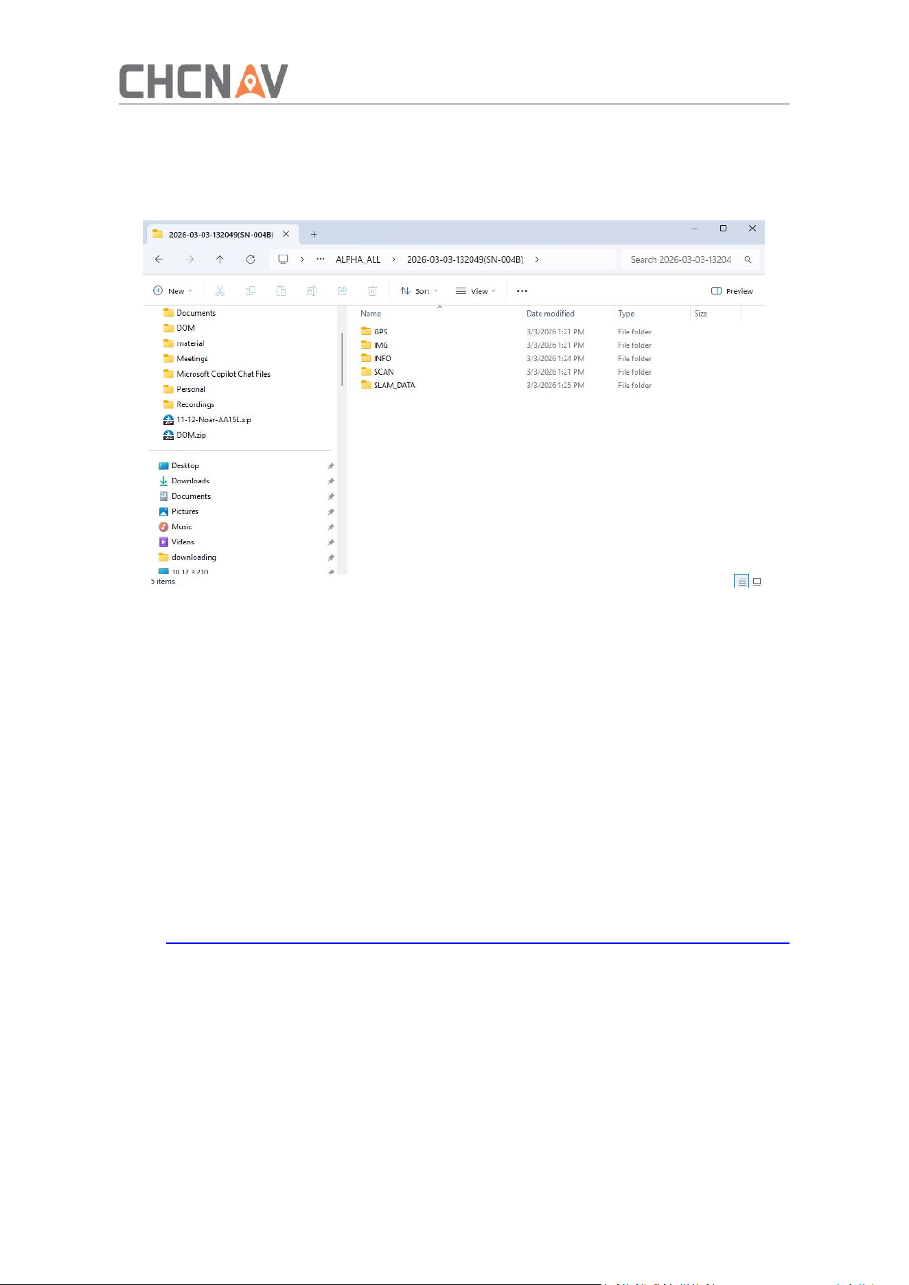
Use the original data cable to connect the device to a computer. Open the ALPHA_ALL
folder then copy or move the required project data to the computer.
Do not process data directly from the device storage.
29
5.1.2 File Structure
The original RS7 project contains five folders: GPS, IMG, INFO, SCAN, and SLAM DATA. The
contents of each folder are as follows:
5.1.3 Data Cleaning
RS7 data cleaning, you can directly delete the engineering data in the RS7 ALPHA _ ALL
folder, or format the RS7 data disk.
5.2 Software Installation
The data processing software for the RS7 is CoPre. CoPre is CHCNAV's proprietary 3D data
intelligent processing software. It primarily supports data processing for laser scanning
systems and aerial survey image data. Data collected by orthophoto cameras and tilt
cameras can be processed into point clouds, panoramic images, orthophoto images, 3D
models, and other outputs. As the core bridge between data acquisition and processing
within CHCNAV's 3D intelligent product ecosystem, CoPre offers comprehensive
functionality with an intuitive, user-friendly interface.
Visit https://support.chcnav.com/portal/en/kb/m3d/software/copre/1-software-package
to download and install the CoPre software.
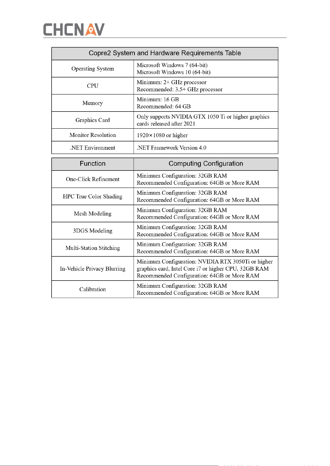
5.2.1 Install
30
5.2.2 Software Registration
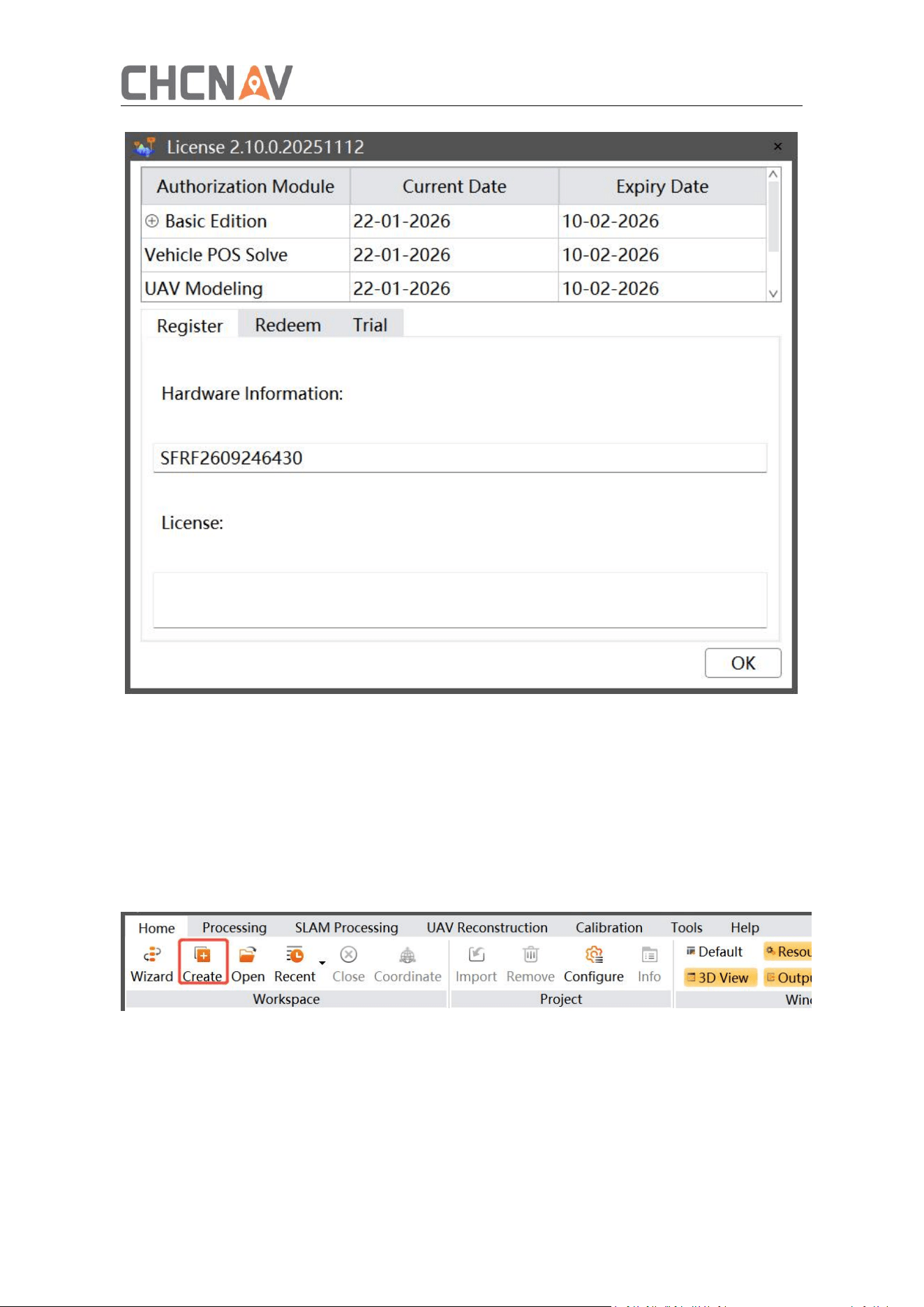
CoPre currently supports three types of licensing.
① Registration: Provide the hardware ID to obtain the registration code for the
after-sales personnel of Shanghai CHCNAV. After entering the registration code, you can
obtain the right to use the corresponding function and duration.
② Exchange: When the computer is connected to the Internet, enter the software
exchange code, and the usage rights corresponding to the function and duration.
③ Trial: When the computer is connected to the Internet, enter the email address or
mobile phone number, enter the sent verification code, and the full-featured software
module can be used for one month. Each computer can be tried twice at most.
31
5.3 Data Resolution
5.3.1 New Construction
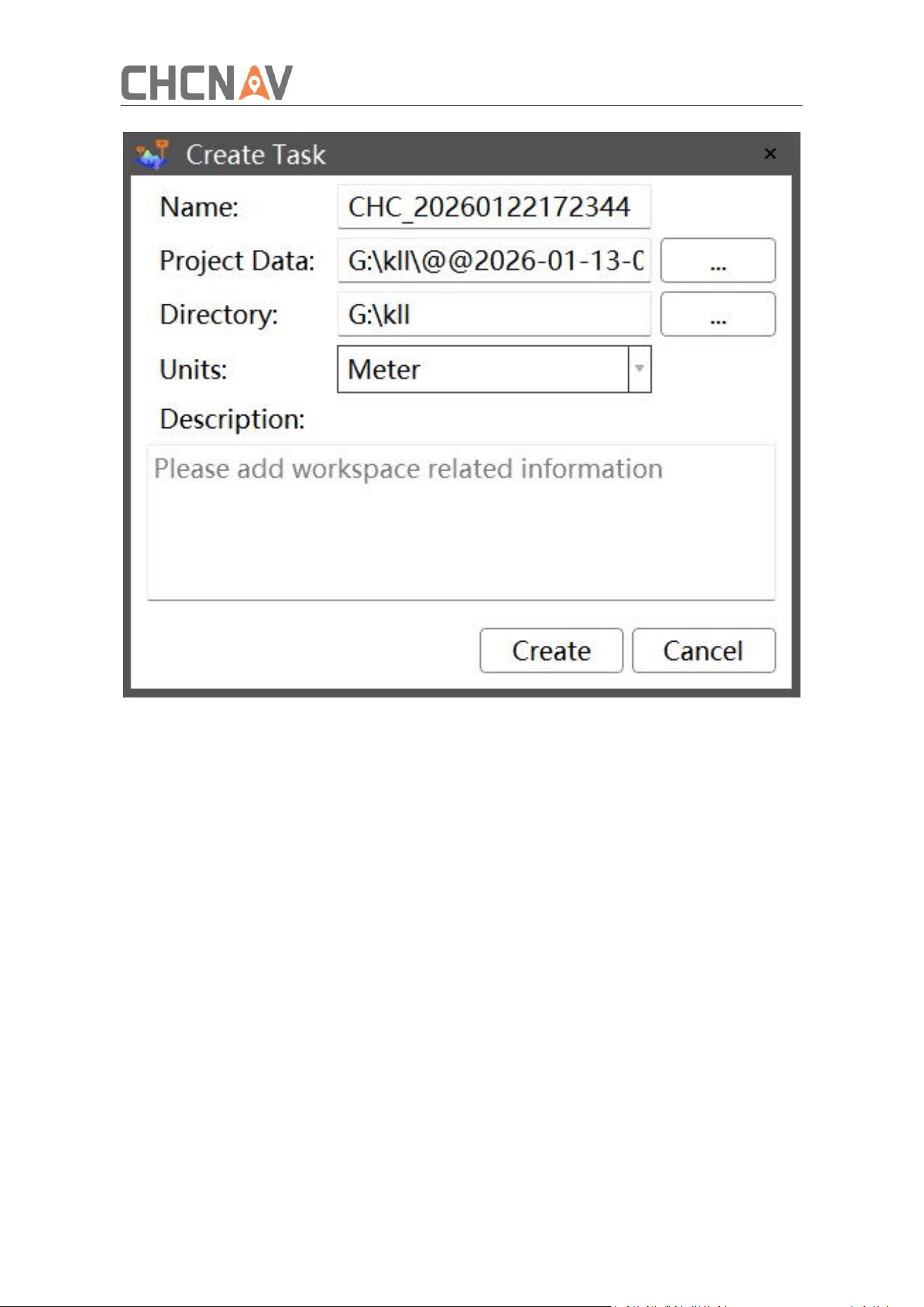
After the software is installed and authorized, open the CoPre software, click "Project
Management-> New", pop up the Create Task dialog box, enter the task name, click the
"..." button on the right side of the project data and task path, and select the project data
and task path, and then click New.
32
Task Name: The name of the newly created work task.
Project data: Original project data copied from the device. Multiple projects can be
selected and processed simultaneously.
Directory: The path for storing intermediate data and achievement data.
Unit: Meter by default.
Description: You can manually enter information about the solution task.
Note: Task names, project data paths, and task paths do not support non-English paths
and spaces.
5.3.2 Coordinate System Setup
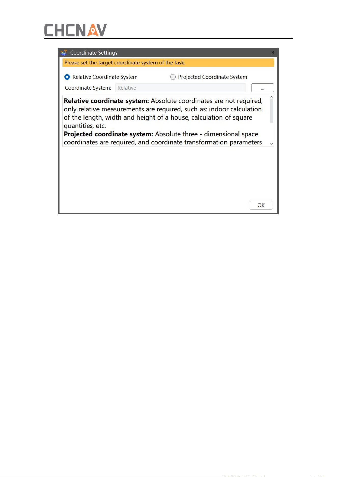
After the new task is completed, enter the coordinate system selection interface.
When absolute coordinates are not required and only relative measurements are
needed—such as for volume calculations, house area measurements, etc.—select the
relative coordinate system. In this mode, post-processing can only output point cloud
results in the relative coordinate system.
33
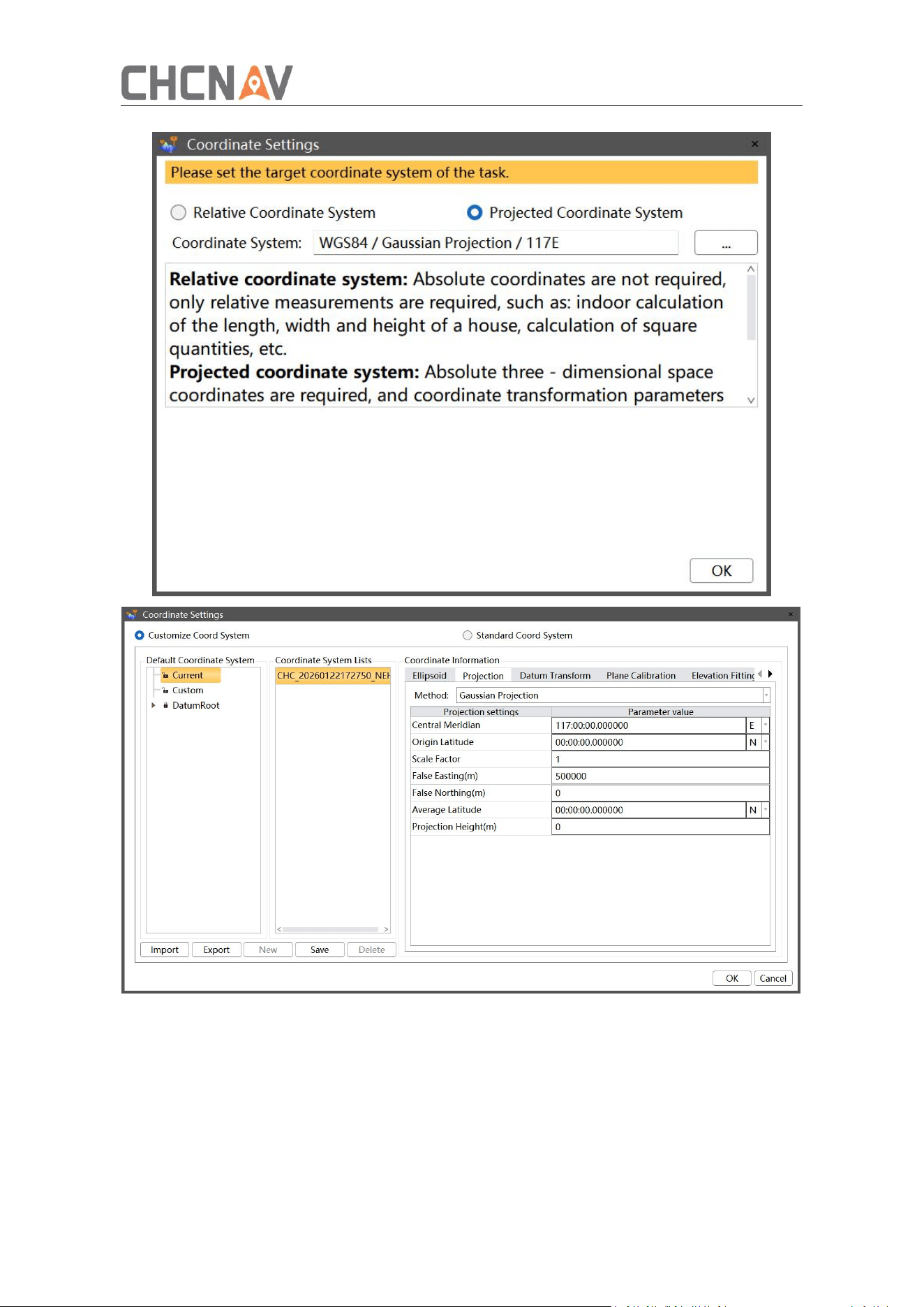
When absolute three-dimensional spatial coordinates are required—such as for
terrain surveying, building facade measurement, or coordinate conversion—select
the projected coordinate system. This system supports customization or the use of
EPSG standard coordinate systems.
34
5.3.3 Real-time Point Cloud Loading
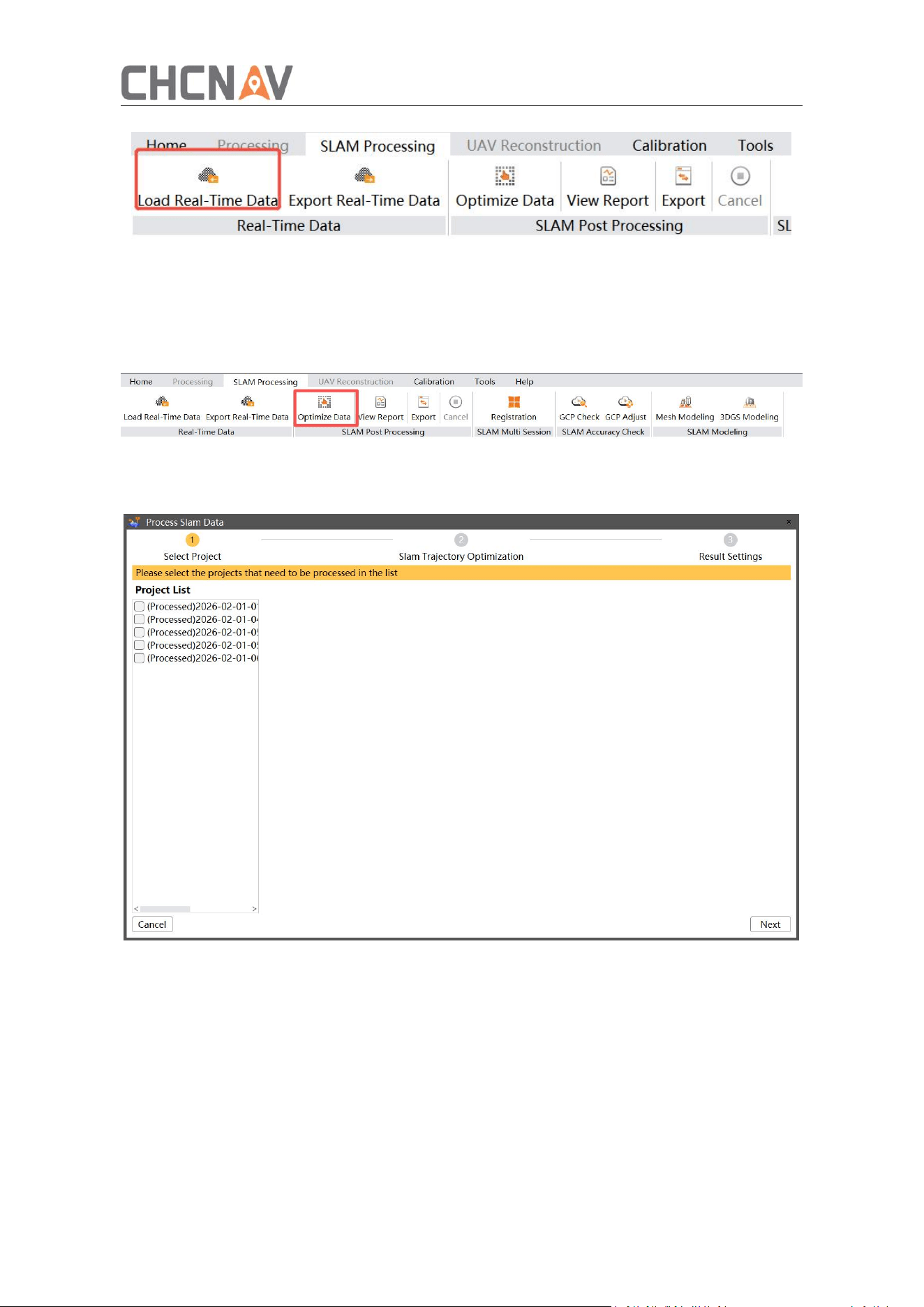
After creating a new project, in the SLAM processing module of CoPre, click to load the
real-time data to display the real-time point cloud results. The real-time point cloud is
stored in the original project/SLAM DATA folder in LAS format.
35
5.3.4 One-click Refinement
When the real-time point cloud effect cannot meet our needs, we can use one-click
refinement to optimize the point cloud.
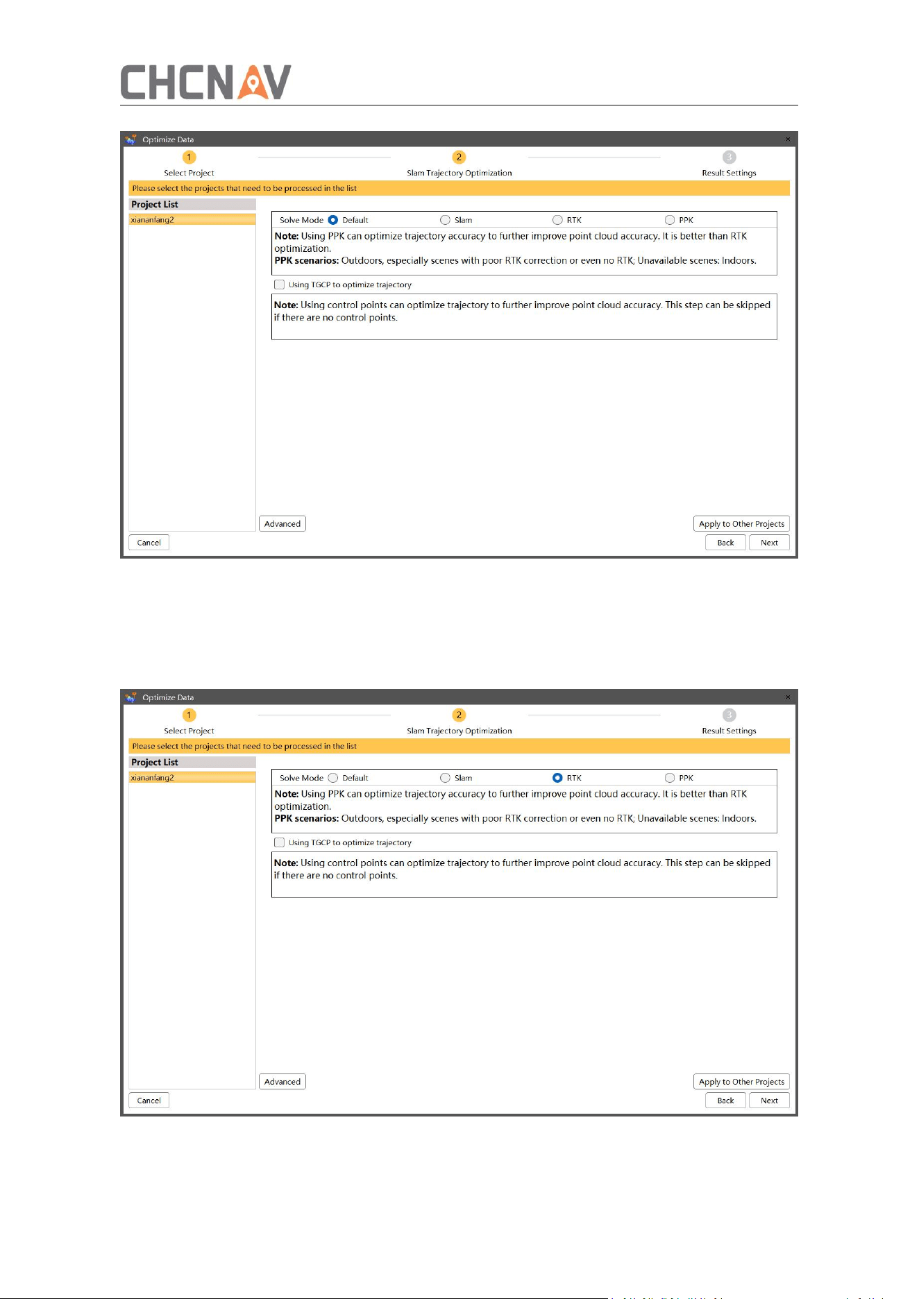
After the coordinate system is set, click the ‘Optimize Data’ option.
①
Select projects: Select the project data that needs to be processed. CoPre supports
selecting multiple projects for processing at the same time.
②
SLAM Trajectory optimization: optimize SLAM results through GNSS data.
Process Mode:
Default: No configuration is required; the system automatically selects the appropriate
coordinate system, such as a relative coordinate system or projected coordinate system.
36
RTK : When GNSS signals are available within the survey area and the system has achieved
a fixed RTK solution, the RTK-optimized trajectory function can be enabled to further
improve trajectory and point cloud accuracy. This function refines the positioning solution
and transforms the point cloud from a relative coordinate framework into an absolute
coordinate reference system.
PPK: When satellite signals are available in the survey area and a physical static base
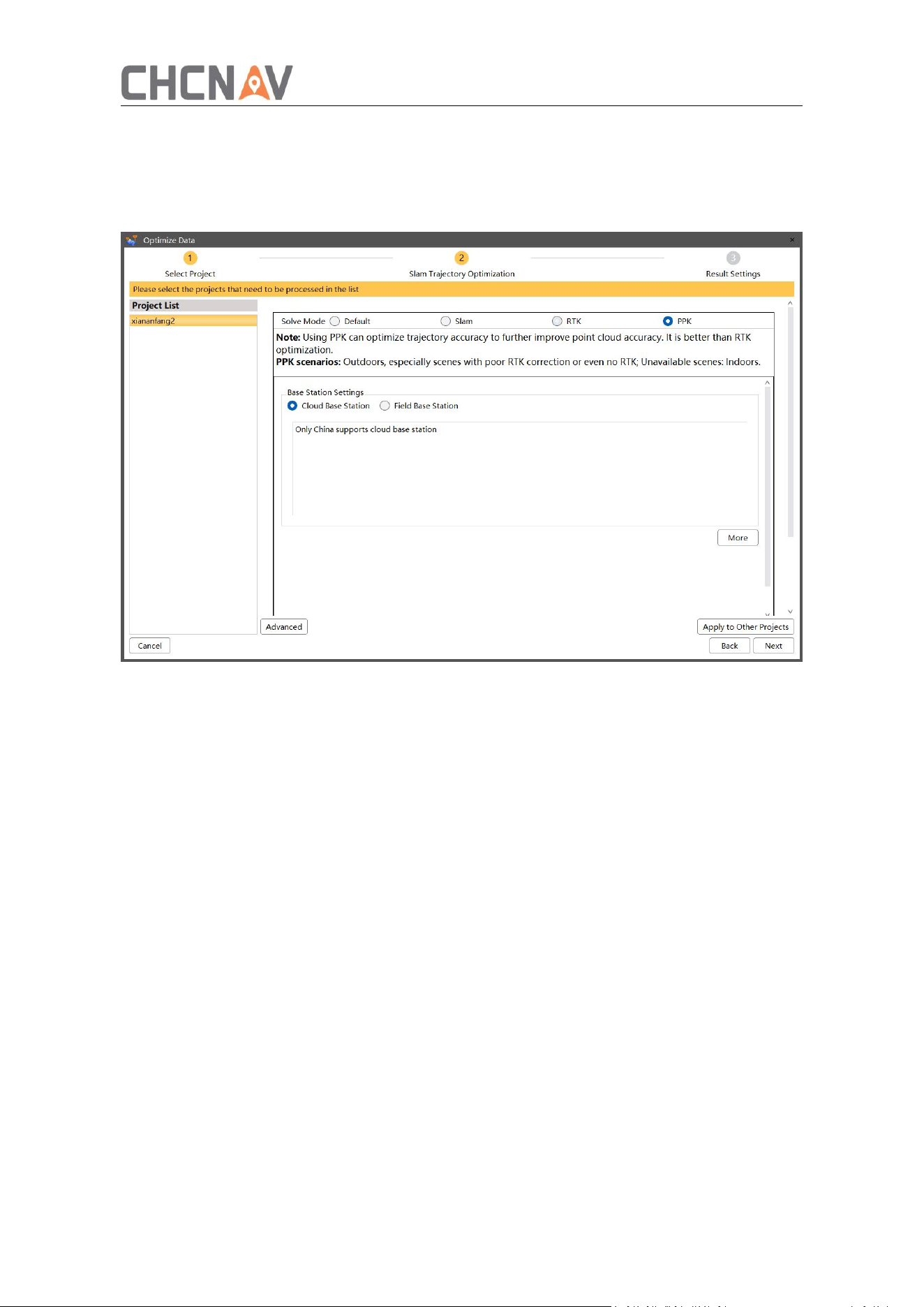
37
station is deployed during data collection—the PPK optimized trajectory function can be
enabled. This function applies a post-processing differential algorithm to generate
high-precision POS data, thereby improving overall data accuracy and converting the point
cloud from a relative coordinate system to an absolute coordinate system.
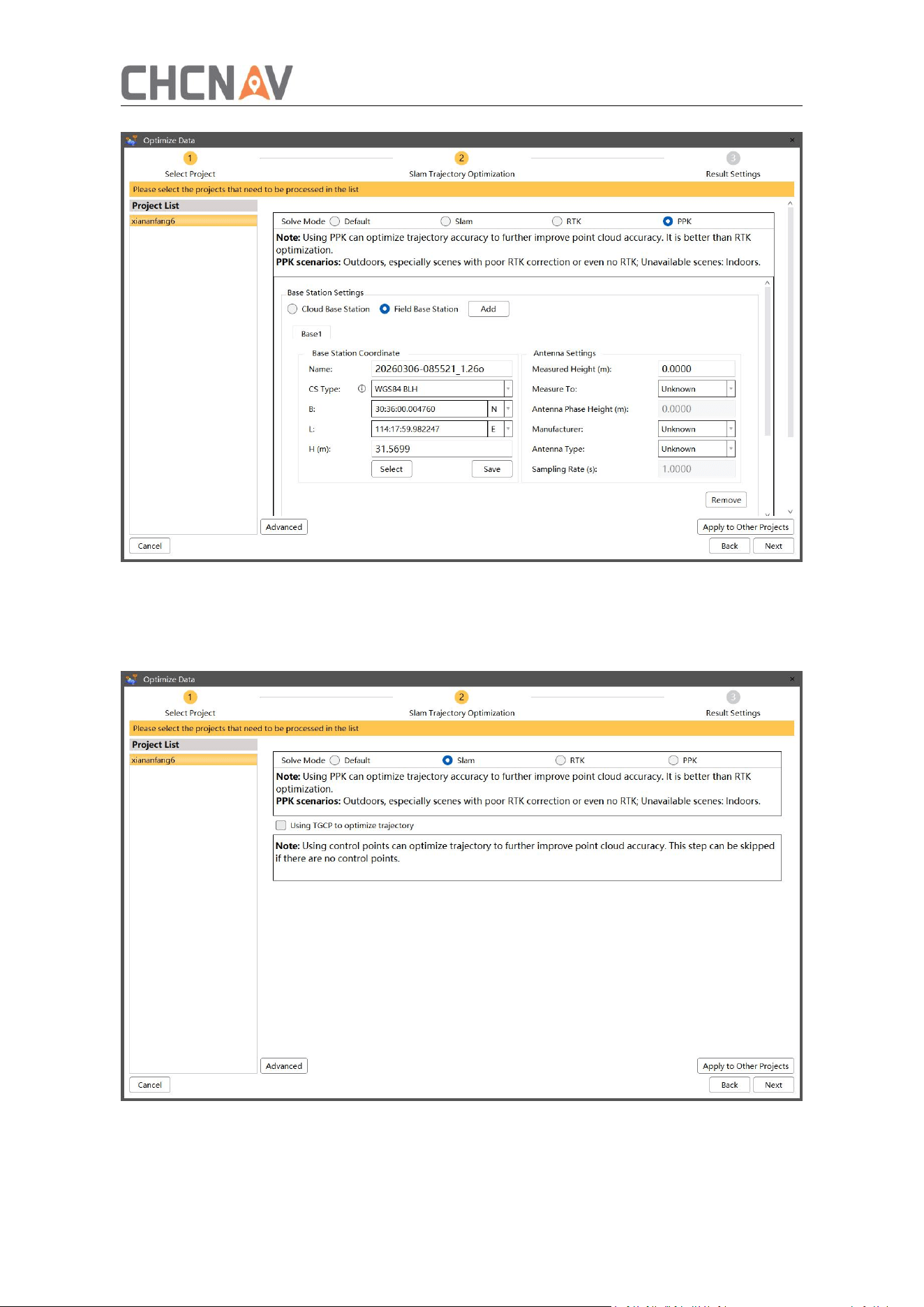
PPK calculation supports the use of CHCNAV cloud base stations or self-built base
stations.
When using a self-erected base station, set it up over a known point and ensure its
static observation covers the device's data collection period. After operation, copy the
base station static file (Renix 3.02 or HCN format) to the original project/GPS/Base
folder. The software will automatically detect it. Alternatively, click Add on the
physical base station interface to manually select the file and enter the base point
coordinates.
38
SLAM: When satellite signals are unavailable in the survey area, or absolute coordinates
are not required and only relative measurements are needed, select Pure SLAM Solution.
Without GNSS optimization, the system will output point clouds in a relative coordinate
system.
Using TGCP to optimize trajectory: Using matched trajectory control points to correct
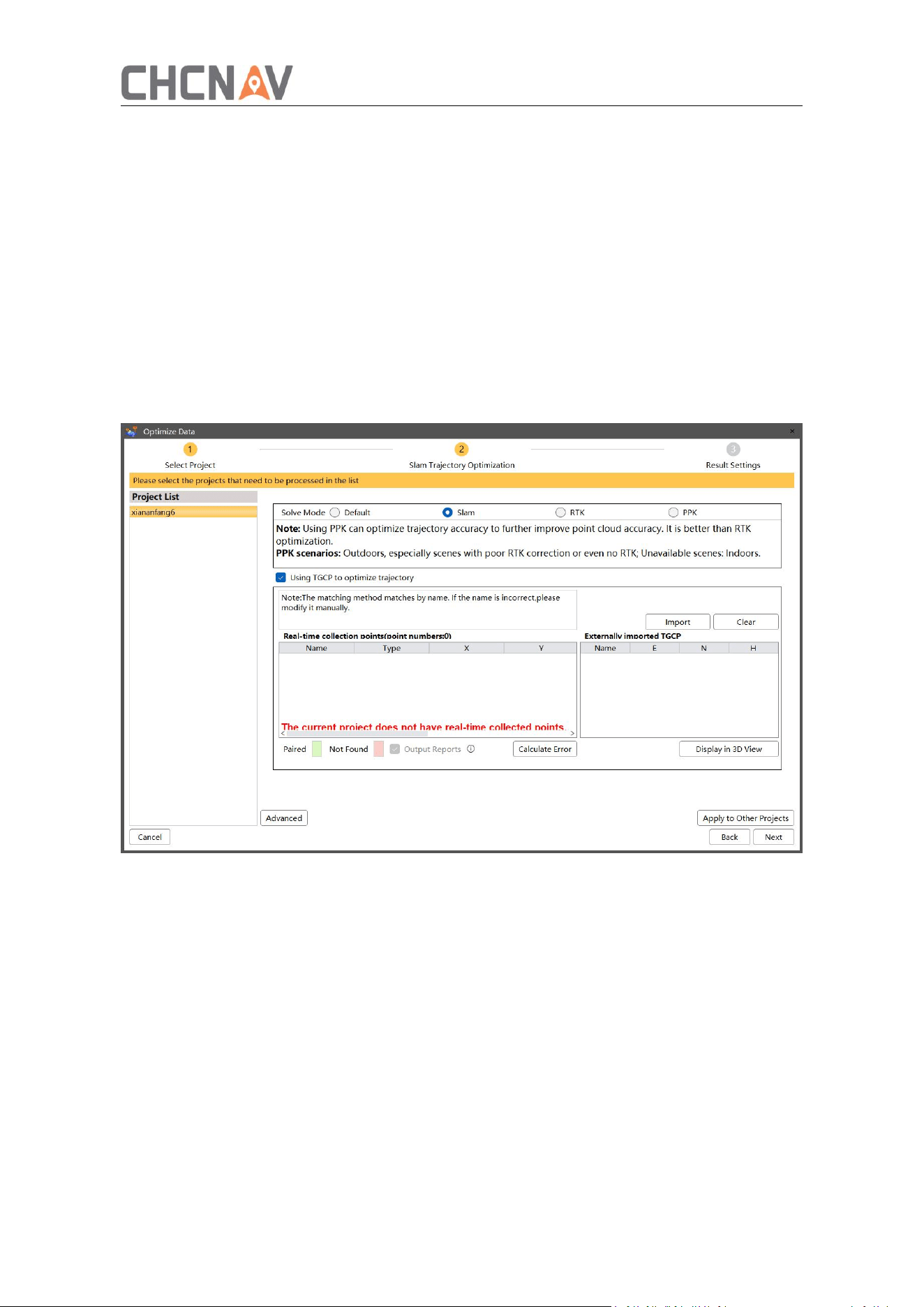
39
SLAM accuracy and transform coordinates.
Trajectory control points are used to correct SLAM accuracy and transform the point
cloud from a relative coordinate system to the trajectory control point coordinate
system. This method is suitable for scenarios where trajectory control points have
been collected in the field. Trajectory control point matching must be completed prior
to use. If no trajectory control points are available, this optimization can be skipped.
Field
‑
collected trajectory control points will appear in the Real
‑
time Acquisition Points
list. Click ‘Import’ above ‘Externally imported TGCP’ on the right to import known
control point coordinates. Supported formats include .csv and .txt. Ensure the
imported point names match the real‑time collected ones—control points will be
matched automatically by name. After matching, the error can be calculated, and
points with large errors can be deselected from the calculation.
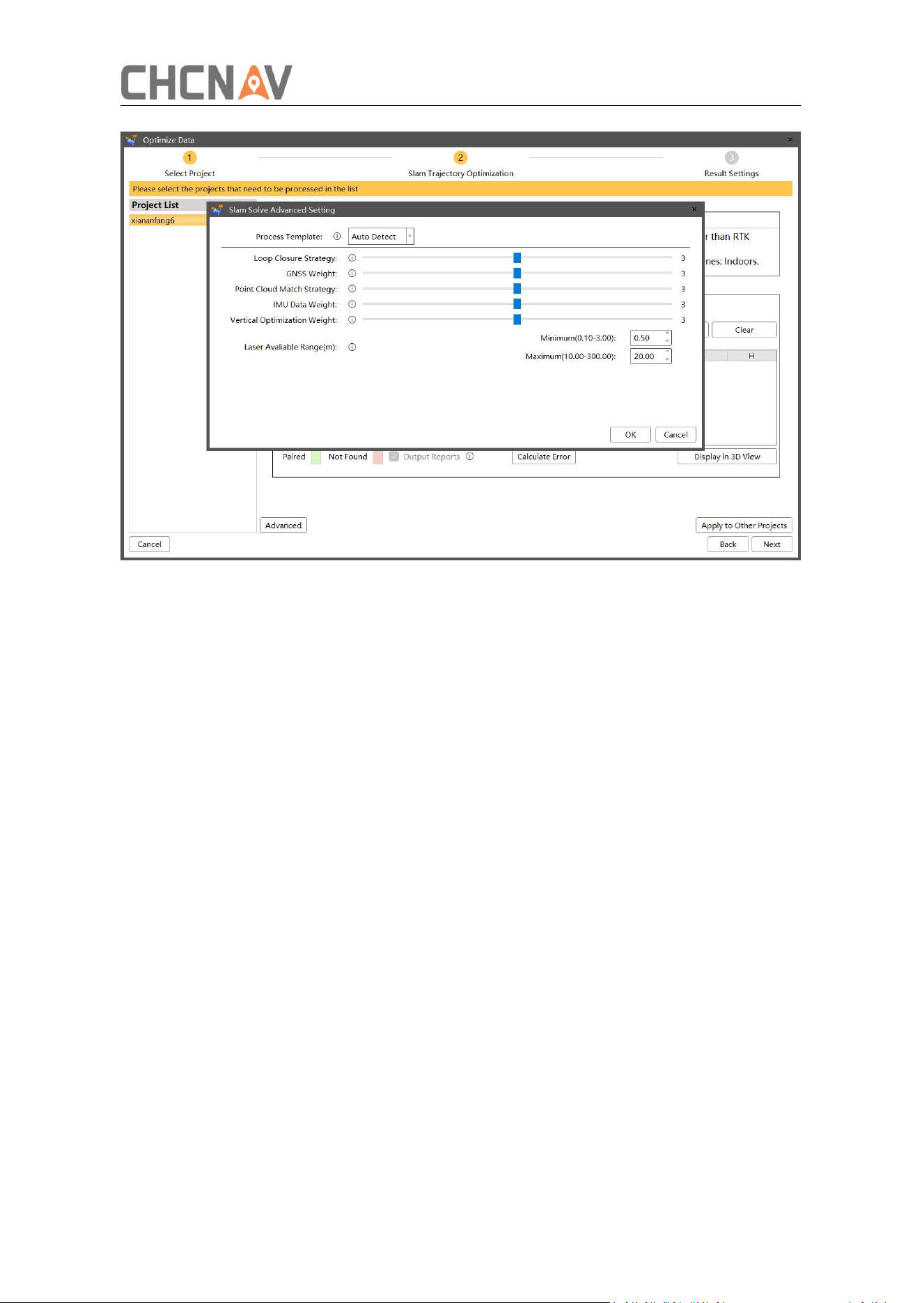
Slam Solve Advanced setting
40
Process Template:
Auto Dectect: The real-time algorithm automatically identifies scene features and selects
the appropriate mode.
Indoor space: Force switch to indoor mode.
Outdoor space: Force switch to outdoor mode.
Narrow space: Force switch to narrow space mode.
Custom mode: Modifying any advanced parameter will activate custom status.
Loop Closure Strategy:
Turn Down: Reduces incorrect loop closures and corrects point cloud stratification caused
by wrong closures, but may lead to misalignment at loop closure positions.
Turn Up: Corrects unclosed trajectory data, but may capture incorrect loop closures and
cause point cloud misalignment.
GNSS Data Weight:
Turn Down: Suitable for data with GNSS signal but point cloud stratification issues; helps
reduce stratification.
Turn Up: Suitable for datasets acquired under stable GNSS conditions. Performance may
degrade in areas with weak or unstable satellite signals.
Point Cloud Matching Strategy:

41
Turn Down: Reduces the LiDAR weighting factor, applies a conservative matching strategy,
and suppresses fine surfaces and noise. This setting is recommended for correcting local
point cloud misalignments caused by matching errors.
Turn Up: Increases the LiDAR weighting factor, applies a more aggressive matching
strategy, and attempts to align fragmented surfaces as completely as possible. This
setting is recommended for weak-feature environments where point cloud drift is likely to
occur.
IMU Data Weight:
Turn Down: Reduces the weighting factor of IMU data to limit its influence on the overall
solution. This setting is recommended for datasets with strong point cloud features and is
effective in mitigating trajectory drift.
Turn Up: Increases the weighting factor of IMU data to strengthen its influence on the
overall solution. This setting is recommended for datasets with weak point cloud features
and can improve robustness in cases where the solution may otherwise fail.
Vertical Optimization Weight:
Turn Down: Reduces the optimization strength in the vertical direction. This setting is
recommended for scenes with significant elevation variations.
Turn Up: Increases the optimization strength in the vertical direction, enhancing the
flatness of ground and ceiling point clouds.
Laser Available Range:
Minimum Range: Defines a spherical exclusion zone centered on the device. Point clouds
within this radius will be filtered out. Increase this value when excessive short-range noise
is present.
Maximum Range: Defines the maximum effective range centered on the device. Point
clouds beyond this radius will be filtered out. Increase this value when long-range point
cloud registration errors occur.
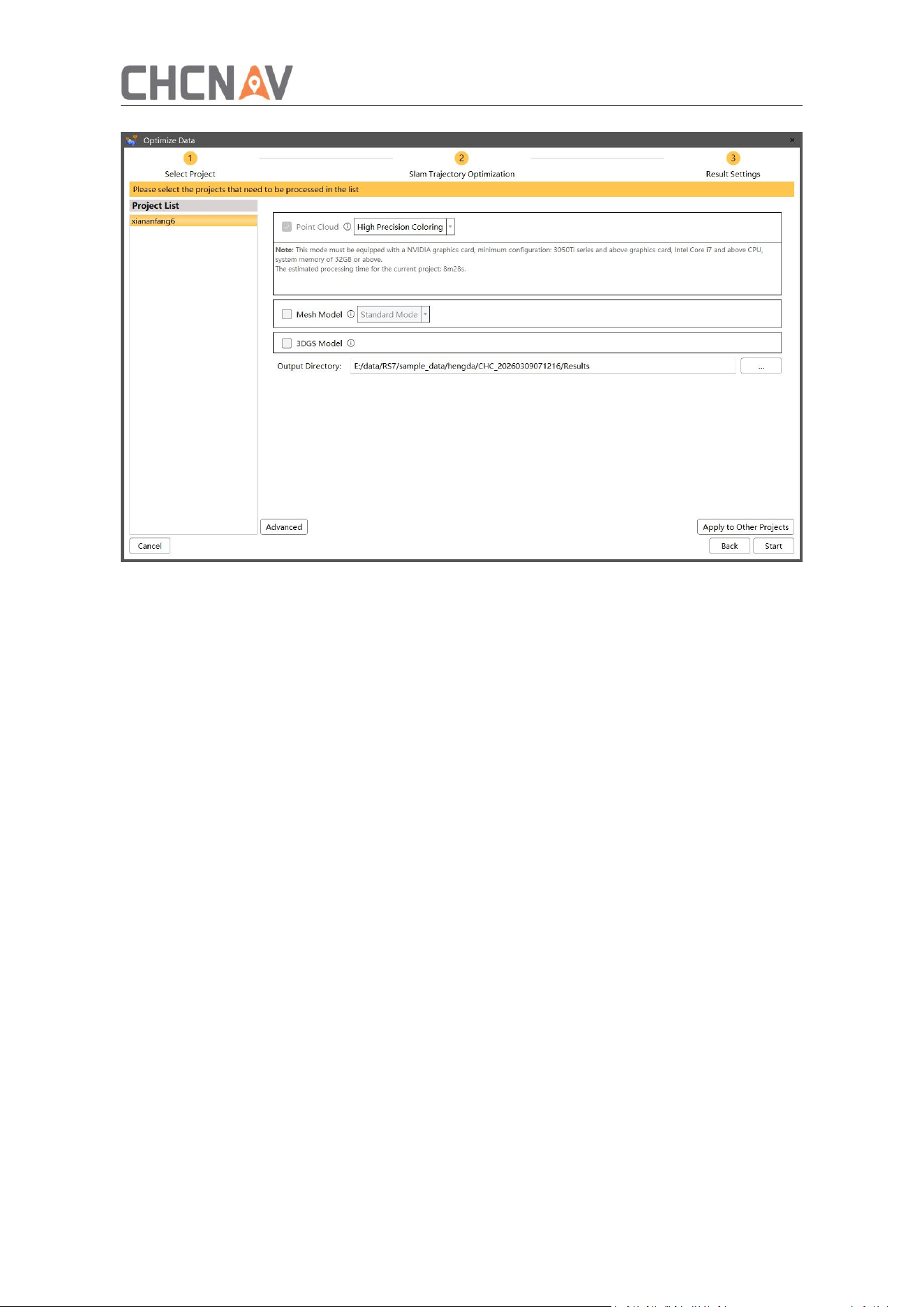
③ Result setting: Calculate and set the engineering data, and output the corresponding
results.
42
Point cloud: Output Point Cloud Data.
Panoramic Images: Output panoramic images.
Mesh Model: Build mesh models: The mesh model is generated by fusing SLAM point
cloud data with images. Currently, the model can be exported in two formats: OSGB and
OBJ.
3DGS Model: Build 3D Gaussian models: Compared with traditional mesh modeling, the
3D Gaussian (3DGS) model provides more realistic visual effects. Currently, the model can
be exported in one format: PLY.
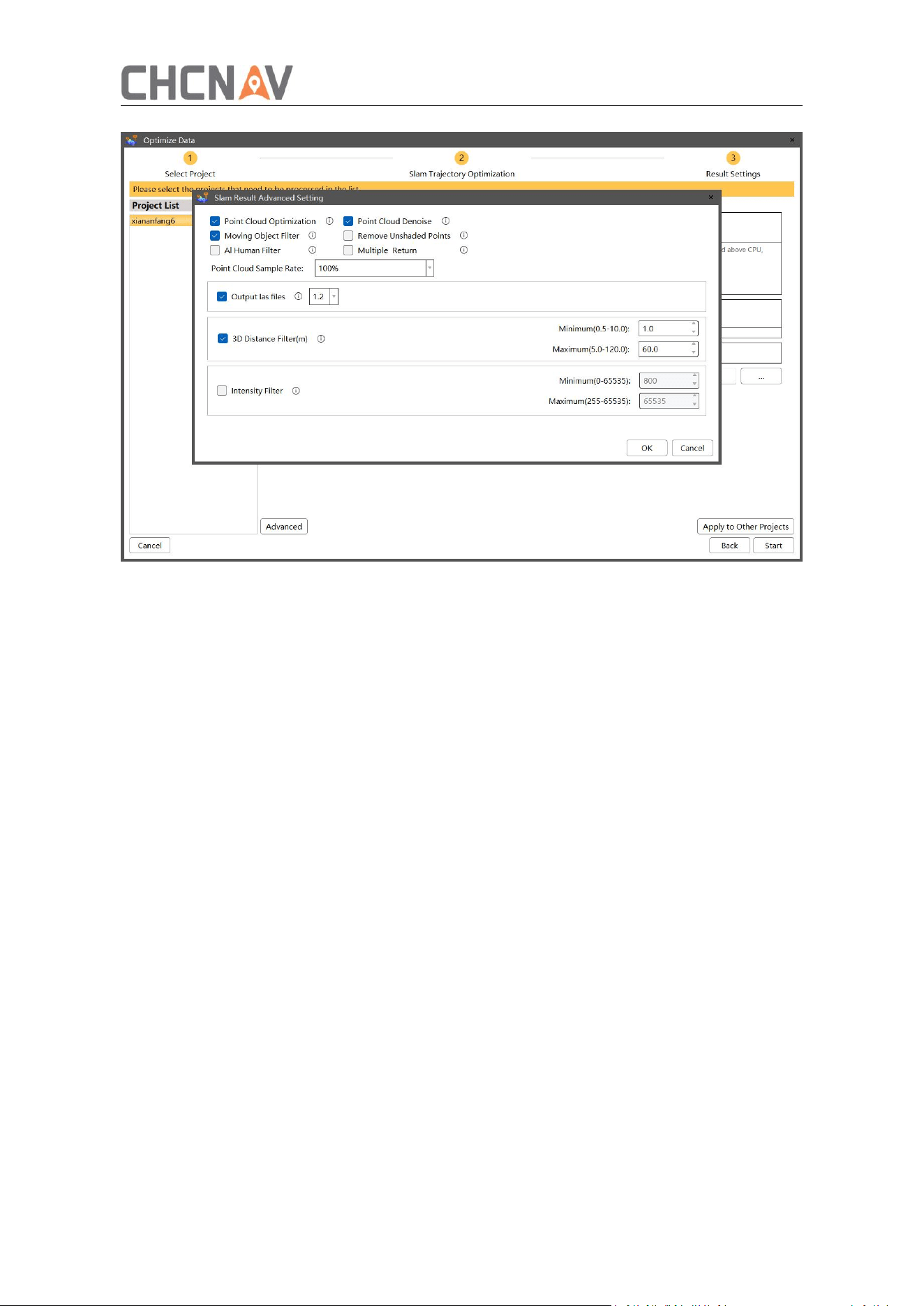
Advanced
43
Point Cloud Optimization:
Reduces the density of the point cloud to enhance the precision of local structural details
in the display.
Point Cloud Denoise:
Removes floating noise from the point cloud to improve the overall visual quality.
Note: This option may also remove some point cloud data in sparsely populated or
unevenly distributed areas
Al Human Filter:
Enabled: Filters out nearly all human points from the point cloud. Note that this may
create partial holes in the point cloud.
Disabled: Disables the filter. Use this setting if undesired point cloud holes appear (e.g.,
caused by posters or photos).
Remove Unshaded Points:
Points with an RGB value of (0, 0, 0) will be excluded from processing. This helps prevent
certain white or dark points from negatively affecting the overall appearance of the point
cloud.
Multiple Return
Checked: Output the multiple echo point cloud data.
Unchecked: Output the single echo point cloud data.
3D Distance Filter:
44
Filter the point cloud by the distance to the center of the laser.
Intensity Filter:
Filter the point cloud by the intensity.
5.3.5 Results Browsing
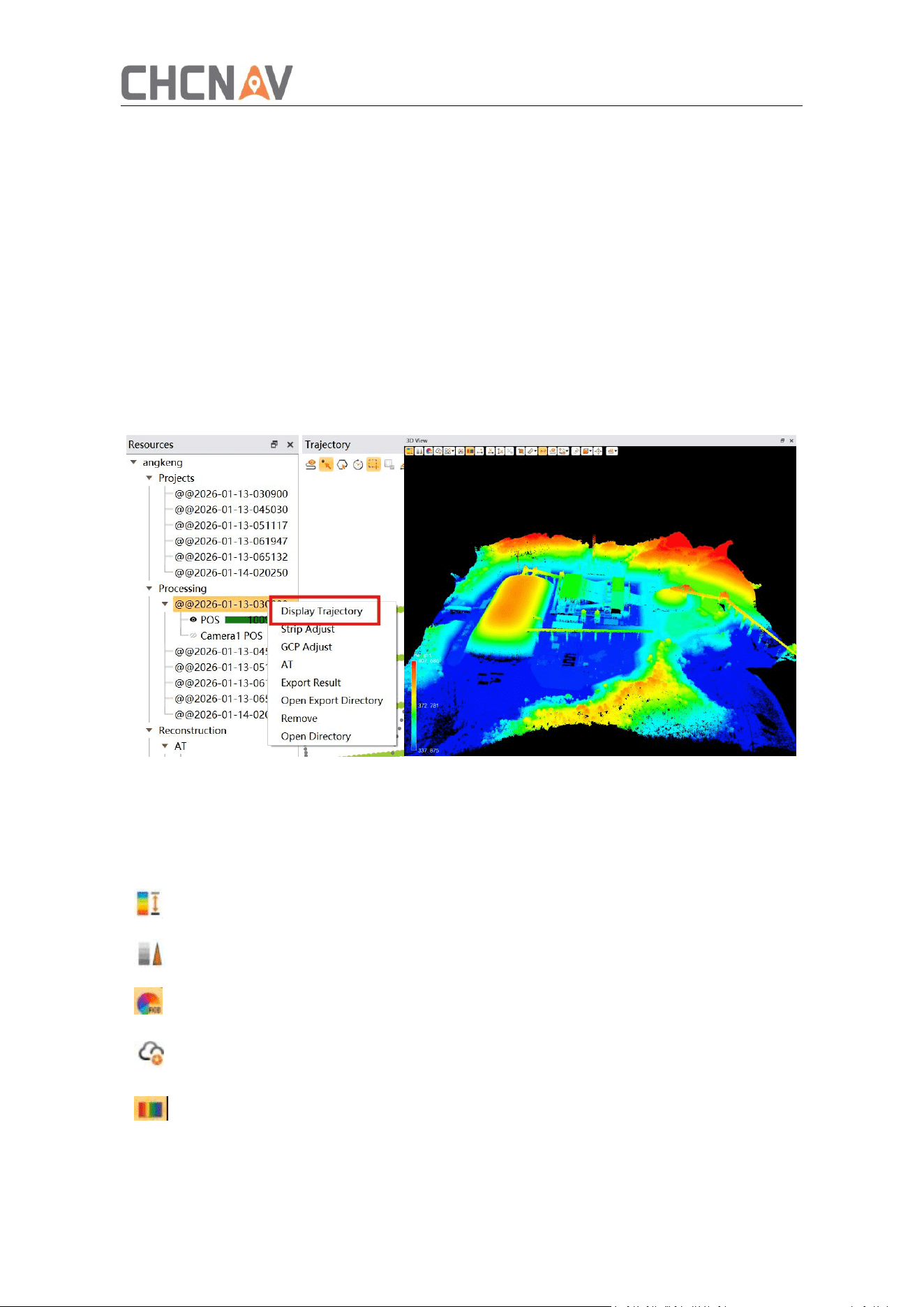
In Outcome Project, select the desired project.
Right-click ‘Display Trajectory’ to load the POS Trajectory into the left view.
Select a portion of the trajectory by either clicking two points on the result trajectory
or holding down the left mouse button to draw a selection box.
The point cloud corresponding to the selected trajectory will be loaded into the Point
Cloud view.
In the 3D view, choose Render to visualize the point cloud.
5.4 Point Cloud Display
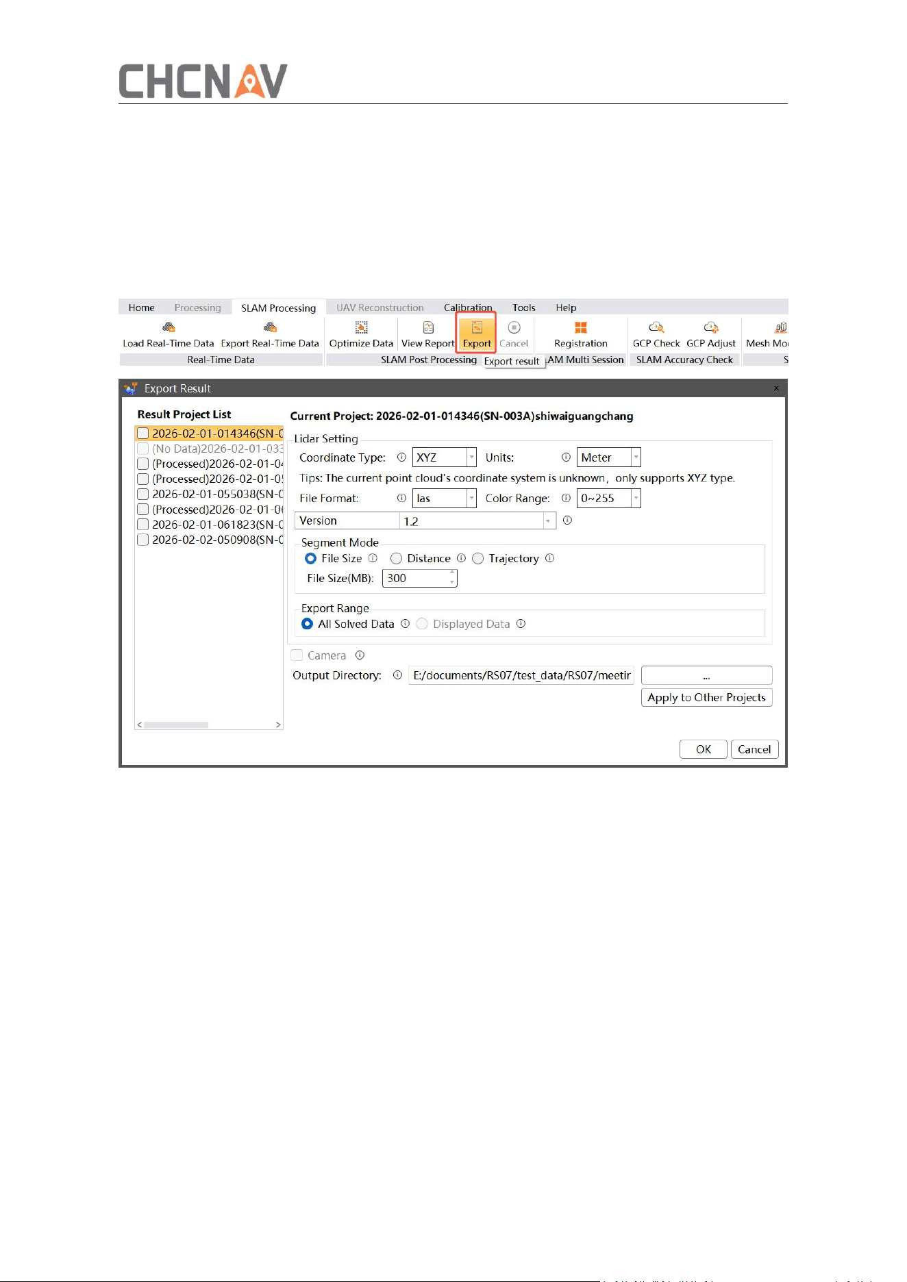
Switch point cloud to elevation rendering
Switch point cloud to intensity rendering
Switch point cloud to color rendering
Switch the point cloud to precision rendering, the smaller the value, the more
accurate the relative precision of the point cloud
Toggle ribbon strips for point clouds
45
5.5 Export Results
After checking the data of the point cloud, if it meets the requirements, the results of
the point cloud can be exported.
In SLAM processing, click the ‘Export’ button, select the project that needs to be
exported, set the coordinate type, file format, coloring range, segmentation, export
range and export directory, and click ‘Confirm’ to export the achievement point cloud.

46
6 Frequently Asked Problems and Solutions
6.1 RS7 Host
The device cannot be turned on: check the battery power of the device and whether
the handle battery is installed in place.
The mobile phone cannot find the WIFI signal of the device: check whether the device
is turned on.
6.2 SmartGo
SmartGo is disconnected from the device during the collection process: check
whether there are other APPs or other devices connected to RS7 WIFI.
The CORS account cannot be successfully logged in the SmartGo collection settings.
Check if the tablet has a mobile network.

47
7 Daily Use and Precautions
7.1 Use
1. For the sake of equipment safety and the possibility of more noise in point clouds,
it is forbidden to use it in rainy, snowy and foggy weather, and it is forbidden to work
under strong wind and dust.
2. It is forbidden to expose equipment and its accessories to extreme temperatures.
The operating temperature and storage temperature shall not be lower or higher
than the temperature specified in the specification.
3. When the product is transferred from cold to warm, water vapor may condense
on some elements inside the scanner. To avoid this, it is recommended to place the
scanner in a sealed plastic bag before transferring it. After the temperature of the
equipment is basically the same as that of the outside world, and the condensed
water evaporates, turn on the equipment again.
7.2 Daily Service Specification
The RS7 measurement system is a complex and precise surveying and mapping system. In
daily carrying, handling, use and storage, only through correct use and proper
maintenance can the accuracy of the instrument be better guaranteed and its service life
be extended. When using this RS7 measurement system, you should pay attention to the
following:
1. The user cannot disassemble the instrument by himself. If there is a failure, please
contact the supplier.
2. This instruction book is a comprehensive instruction book for RS7 measurement system.
Please choose the corresponding operation method according to the specific operation. If
you have any questions, please contact the technical staff of Shanghai CHCNAV.
3. Connect the equipment strictly according to the connection method in the installation
manual, check whether the screws and plug-ins of the structural parts are loose, and
regularly clean the surface of the equipment, the laser window mirror and the camera
lens with a cleaning kit. Follow the following steps during the cleaning process:
a. Choose a place with less dust, and use a lens cloth to remove dust from the surface of
the lidar and camera.
b. Use wet wipes to gently laser window mirrors and camera lenses, as well as residual
dust and fingerprints in gaps.
c. Clean the main body of the LiDAR and camera with a wet wipe, using a soft towel if
necessary. Note: Do not use alcohol or other corrosive liquids on non-metallic parts of
the main body or camera.
4. Prevent the instrument from being strongly impacted or vibrated.

48
5. After the instrument is used, it should be packed in time. Before packing, it is necessary
to ensure that the instrument and the instrument box are dry.
6. If the instrument needs to be operated continuously for extended periods or under
special conditions such as high humidity, please consult the Shanghai CHCNAV Technology
Center for relevant precautions. Failures occurring under such special conditions are not
covered by the product warranty.
7. Handle the equipment with care during use to avoid contamination or surface scratches.
Surveyors or any personnel must not sit on the equipment or its packaging under any
circumstances.
7.3 Equipment Transportation
1. The equipment is provided with a dedicated instrument box. During transportation or
relocation, place the equipment inside the instrument box and secure it in position using
seat belts or other restraining measures. Avoid collisions between the instrument box and
the vehicle body to minimize impact and vibration.
2. During transportation, ensure that consignors or handlers avoid improper operations.
Inform all personnel that the equipment is a precision instrument requiring careful
handling. Clearly label the equipment as ‘Fragile’.
3. For express shipping, in addition to the instrument box, an outer carton should be used.
Fill the space between the instrument box and the outer carton with shock-absorbing
materials such as cotton or foam.
7.4 Equipment Storage
1. When not in use, place the equipment neatly inside its instrument box. The instrument
box should be placed on a table or shelf in an organized manner and must not be stacked.
2. The storage room should be clean, dry, and well-ventilated. Replace the desiccant in the
instrument box regularly to maintain optimal humidity conditions.
Warning:
The band 5150-5350MHz indoor use only.
49
CHC Navigation
Building C, 577 Songying Road, Qingpu, District,
201703 Shanghai, China
Tel: +86 21 542 60 273 | Fax: +86 21 649 50 963
Email: sales@chcnav.com | support@chcnav.com
Skype: chc_support
Website: www.chcnav.com
FCC Warning
15.19 Labeling requirements.
This device complies with part 15 of the FCC Rules. Operation is subject to the following two conditions: (1) This device may not cause
harmful interference, and (2) this device must accept any interference received, including interference that may cause undesired
operation.
15.21 Information to user.
Any Changes or modifications not expressly approved by the party responsible for compliance could void the user's authority to operate
the equipment.
15.105 Information to the user.
Note: This equipment has been tested and found to comply with the limits for a Class B digital device, pursuant to part 15 of the FCC
Rules. These limits are designed to provide reasonable protection against harmful interference in a residential installation. This
equipment generates uses and can radiate radio frequency energy and, if not installed and used in accordance with the instructions,
may cause harmful interference to radio communications. However, there is no guarantee that interference will not occur in a particular
installation. If this equipment does cause harmful interference to radio or television reception, which can be determined by turning the
equipment off and on, the user is encouraged to try to correct the interference by one or more of the following measures:
-Reorient or relocate the receiving antenna.
-Increase the separation between the equipment and receiver.
-Connect the equipment into an outlet on a circuit different from that to which the receiver is connected.
-Consult the dealer or an experienced radio/TV technician for help.
Absorption Rate (SAR) information:
This device meets the government's requirements for exposure to radio waves. The guidelines are based on standards that were
developed by independent scientific organizations through periodic and thorough evaluation of scientific studies. The standards include
a substantial safety margin designed to assure the safety of all persons regardless of age or health.
FCC RF Exposure Information and Statement
The SAR limit of USA (FCC) is 1.6 W/kg averaged over one gram of tissue. This device was tested for typical body-worn operations with
the back of the device kept 10mm from the body. To maintain compliance with FCC RF exposure requirements, use accessories that
maintain a appropriate separation distance between the user's body and the back of the device. The use of belt clips, holsters and
similar accessories should not contain metallic components in its assembly. The use of accessories that do not satisfy these
requirements may not comply with FCC RF exposure requirements, and should be avoided. Use only the supplied or an approved
antenna.