Digital Signal Processor
with Sub Eects
Product Manual
FCC Warning Statement
Changes or modications not expressly approved by the party responsible for compliance could void the user’s authority to
operate the equipment. This equipment has been tested and found to comply with the limits for a Class B digital device, pursuant
to Part 15 of the FCC Rules. These limits are designed to provide reasonable protection against harmful interference in a
residential installation. This equipment generates uses and can radiate radio frequency energy and, if not installed and used
in accordance with the instructions, may cause harmful interference to radio communications. However, there is no guarantee
that interference will not occur in a particular installation. If this equipment does cause harmful interference to radio or television
reception, which can be determined by turning the equipment o and on, the user is encouraged to try to correct the interference
by one or more of the following measures:
-- Reorient or relocate the receiving antenna.
-- Increase the separation between the equipment and receiver.
-- Connect the equipment into an outlet on a circuit dierent from that to which the receiver is connected.
-- Consult the dealer or an experienced radio/TV technician for help.
FCC Radiation Exposure Statement
The antennas used for this transmitter must be installed to provide a separation distance of at least 20 cm from all persons and
must not be co-located for operating in conjunction with any other antenna or transmitter.
This device complies with Part 15 of the FCC Rules. Operation is subject to the following two conditions:
(1)This device may not cause harmful interference.
(2)This device must accept any interference received, including interference that may cause undesired operation.

AXIS DSP
1
DAYTONAUDIO
Welcome
Thank you for choosing the Dayton Audio AXIS-8 Digital Signal Processor. Designed for
precise control, the AXIS-8 delivers powerful DSP capabilities through an intuitive control
platform, making it easy to optimize audio performance across home, mobile, and custom
systems.
Using AXIS Control software, you can quickly congure inputs, routing, and advanced
processing features like parametric EQ, crossovers, delay, and bass enhancement tools.
With support for line-level, optical, Bluetooth, and USB inputs, the AXIS-8 integrates
seamlessly into both modern and legacy setups.
Built for real-world exibility, the AXIS-8 includes a mobile-ready wiring harness for clean
vehicle installation. Whether you’re tuning a simple system or building a fully active setup,
the AXIS-8 gives you the control to dial it in.
Contents
Welcome .............................................................................................................................. 1
Contents .............................................................................................................................. 1
What’s In the Box ............................................................................................................... 2
Unpacking ........................................................................................................................... 2
Panels and Controls ........................................................................................................... 3
Connecting To Power ......................................................................................................... 4
DC Barrel Jack ............................................................................................................ 4
Wiring Harness ........................................................................................................... 4
Power Mode Switch .................................................................................................... 4
Hooking Up ......................................................................................................................... 5
Line Level Input .......................................................................................................... 5
Speaker Level Input ................................................................................................... 5
Optical TOSLINK......................................................................................................... 5
Bluetooth Audio .......................................................................................................... 6
USB .............................................................................................................................. 6
Input Level Switch ...................................................................................................... 7
Output Level Switch ................................................................................................... 7
Wired Remote (Optional) ................................................................................................... 8
Using Mounting Brackets (Optional) ................................................................................ 9
AXIS Control Software ..................................................................................................... 10
Connectivity and System Requirements.................................................................... 10
Setup Wizard ..............................................................................................................11
Saving Presets ...................................................................................................................11
Factory Reset .................................................................................................................... 12
Firmware Update .............................................................................................................. 12
Block Diagram .................................................................................................................. 13
Dimensional Drawings ..................................................................................................... 14
Wiring Harness ................................................................................................................. 15
Troubleshooting ............................................................................................................... 16
Specications ................................................................................................................... 17
AXIS DSP
2
DAYTONAUDIO
Unpacking
Carefully remove the AXIS-8 and all included accessories from the packaging. Inspect
each item for any visible damage that may have occurred during shipping. If any damage is
found, notify the shipping carrier promptly.
If the product shows signs of shipping damage, retain all packaging materials for inspection
and do not install the unit until the issue has been resolved.
It is recommended to keep the original packaging and packing materials for future transport
or storage. Using the original packaging helps ensure the unit remains protected during
handling.
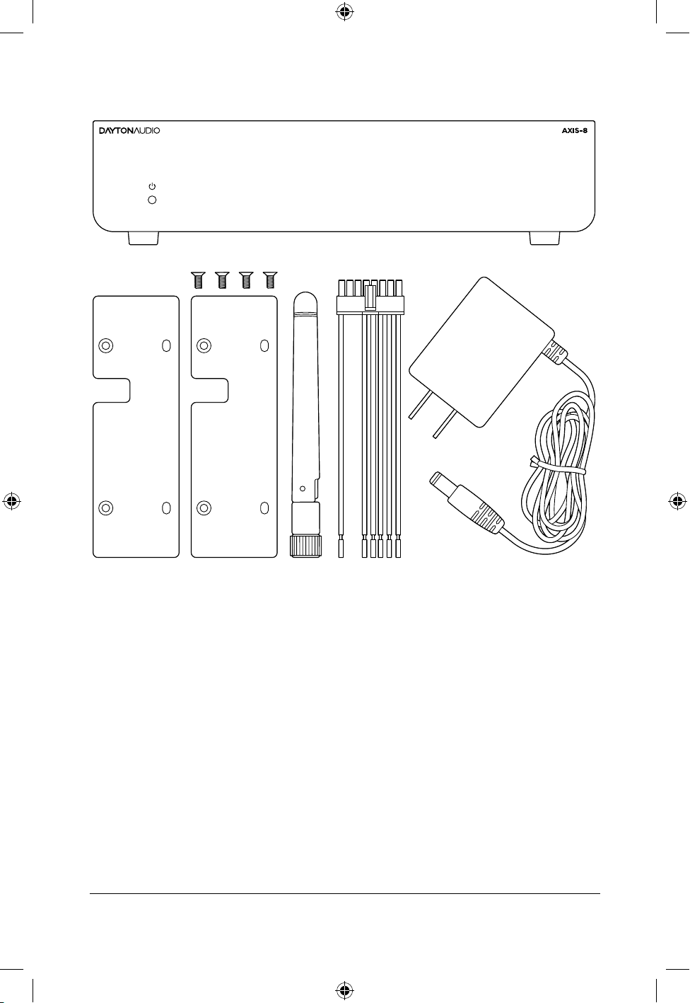
What’s In the Box
AXIS-8
Mounting Bracket Kit Bluetooth
Antenna
Wiring
Harness
DC Power Supply
AXIS DSP
3
DAYTONAUDIO
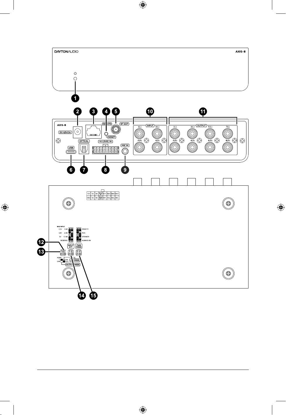
Panels And Controls
1. Status LED
2. 12V DC Input
3. Wired Remote Connection
4. Factory Reset Button
5. Bluetooth Antenna
6. USB-C Input
7. Optical Toslink Input
8. Wiring Harness
9. CALMIC Input
10. Line Inputs (RCA)
11. Line Outputs (RCA)
12. LED Mode Switch
13. Output Mode Control
14. Input Attenuation Control
15. Power Mode Control
AXIS DSP
4
DAYTONAUDIO
Connecting To Power
DC Barrel Jack
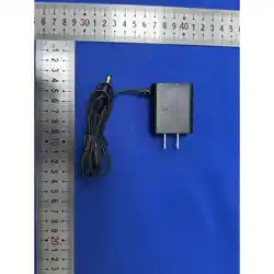
Use the included 12V 1A power adapter with the AXIS-8 DC barrel jack. This port uses a
standard 2.1 mm center-positive DC barrel connector. Compatible 12V power supplies may
also be used.
Wiring Harness
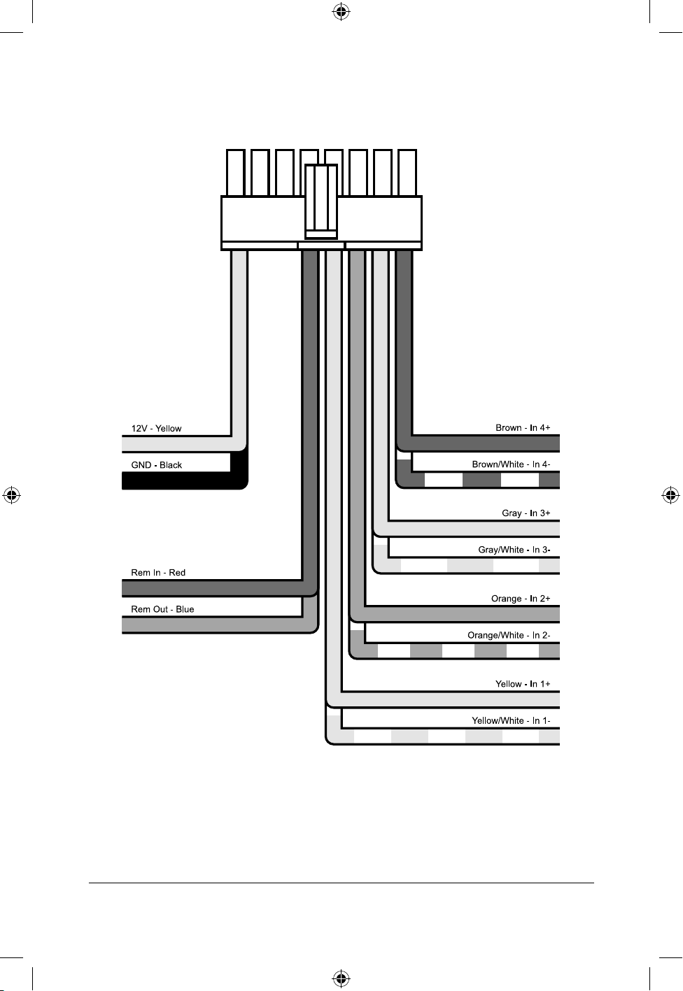
The wiring harness supports individual 12V and ground wires for powering the AXIS-8 with
a car battery. This voltage will accept the voltage uctuations typical for a car battery and
will even reject noise present in the voltage input.
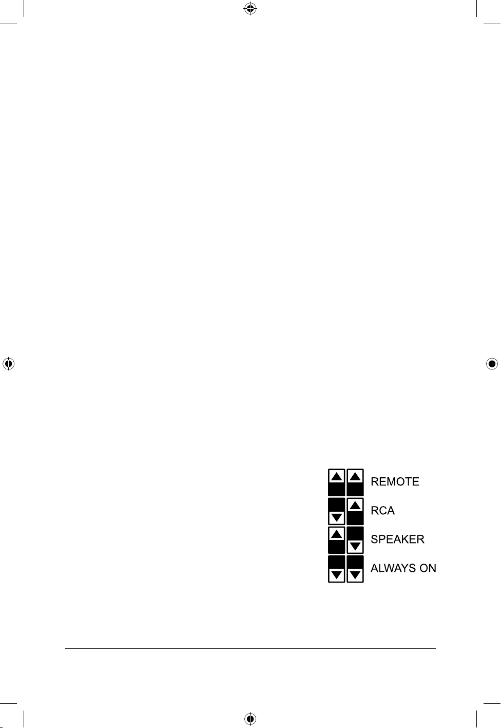
Power Mode Switch
The AXIS-8 includes four power mode settings to control how the unit turns on and enters
standby.
Remote
For car audio installations. The AXIS-8 turns on when 12V is
applied to the remote input wire. If no 12V signal is present,
the unit remains o.
RCA
The AXIS-8 turns on when signal is detected at the RCA
inputs. If no signal is detected for the selected delay time,
the unit enters standby.
Speaker
The AXIS-8 turns on when signal is detected at the speaker-
level inputs. If no signal is detected for the selected delay
time, the unit enters standby.
Always On
The AXIS-8 remains on and will not enter standby.

AXIS DSP
5
DAYTONAUDIO
Hooking Up
The AXIS-8 is set to receive audio from the analog inputs by default. Input routing and
channel assignment are congured in the AXIS Control software.
Line Level Input
Use RCA cables to connect the source to the AXIS-8 line-level inputs. Up to four input
channels (IN1–IN4) are supported. For stereo sources, connect the left and right outputs to
IN1 and IN2.
Speaker Level Input (Wiring Harness)
The included wiring harness accepts up to four speaker-level input channels (IN1–IN4).
Inputs support up to 40 Vrms (single-ended) and 80 Vrms (dierential).
This connection is used when a line-level signal is not available, such as with a factory-
installed car radio.
Connect the speaker output wires from the source unit to the corresponding input wires on
the AXIS-8.
Optical TOSLINK
The AXIS-8 supports 2-channel PCM input via the optical TOSLINK connection. Select the
optical input in the AXIS Control software. The signal is routed to IN1 and IN2.

AXIS DSP
6
DAYTONAUDIO
Hooking Up (cont.)
Bluetooth Audio
Bluetooth audio is built into the AXIS-8 for convenient wireless streaming.
For Bluetooth control, please reference AXIS Control Connectivity on pg. 10.
1. Connect the included Bluetooth antenna to the rear of the AXIS-8.
2. Enable Bluetooth as an input source in the AXIS Control App.
3. Using a smartphone, tablet, computer, or other device capable of transmitting
Bluetooth audio, go to the device’s settings and scan for available Bluetooth
devices.
4. Look for and select “AXIS-8-AUDIO” in the device list and begin pairing.
USB
The USB-C port provides 2-channel digital audio input and communication with the AXIS
Control software.
Connect the source device to the USB-C port on the AXIS-8. Select USB as the input
source in the AXIS Control software. The audio signal is routed to IN1 and IN2.
AXIS DSP
7
DAYTONAUDIO
Input Level Switch
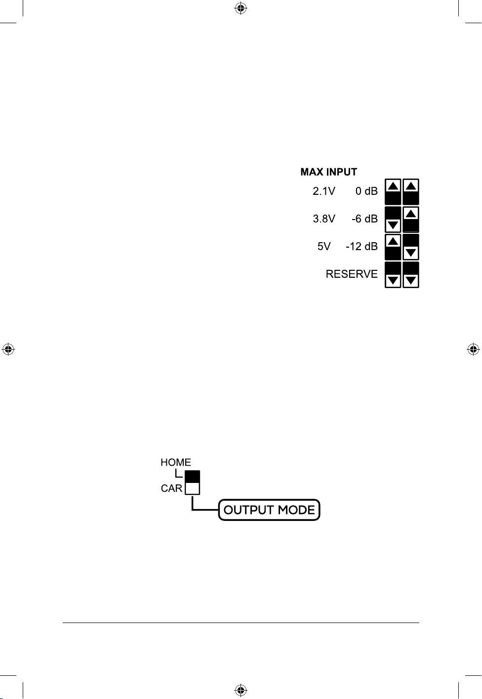
To maximize compatibility, the AXIS-8 has a switch that controls the maximum line level
voltage that can be present on the RCA inputs while ensuring clean audio output. Home audio
equipment and car audio equipment have dierent voltage ranges, with car audio equipment
exceeding the typical 2V maximum found in home audio equipment. Measure a 1KHz sine
wave with a multimeter connected to your audio source’s RCA plug, if possible.
2.1V (0dB)
This mode should be used in most home audio use cases.
Typical home audio and pro audio input sources will output
a line level voltage between 0V and 2V.
3.8V (-6dB)
This mode is ideal for most car audio installations, allowing
typical car audio voltages.
5V (-12dB)
This mode should be used in car audio installations where
the audio source is very high, exceeding 3.8V. If unsure or if
you are unable to measure your signal, use the 3.8V mode.
If any unexpected distortion is heard, try this 5V mode.
Output Level Switch
To ensure compatibility with both home audio ampliers and car audio ampliers, the AXIS-8
has an output mode level switch. This controls the maximum output voltage that the AXIS-8
will output to the RCA jacks. The AXIS-8 features a line level driver, that can boost the voltage
to a higher level than the input voltage. This eect is much larger in the CAR output mode.
Home (2V)
The AXIS-8 will not output a line level voltage exceeding 2V, ensuring compatibility with
home audio ampliers.
Car (5V)
The AXIS-8 will output a higher output voltage than in home audio mode, but will not exceed
5V. These voltage levels are more suitable for car audio style ampliers.
AXIS DSP
8
DAYTONAUDIO
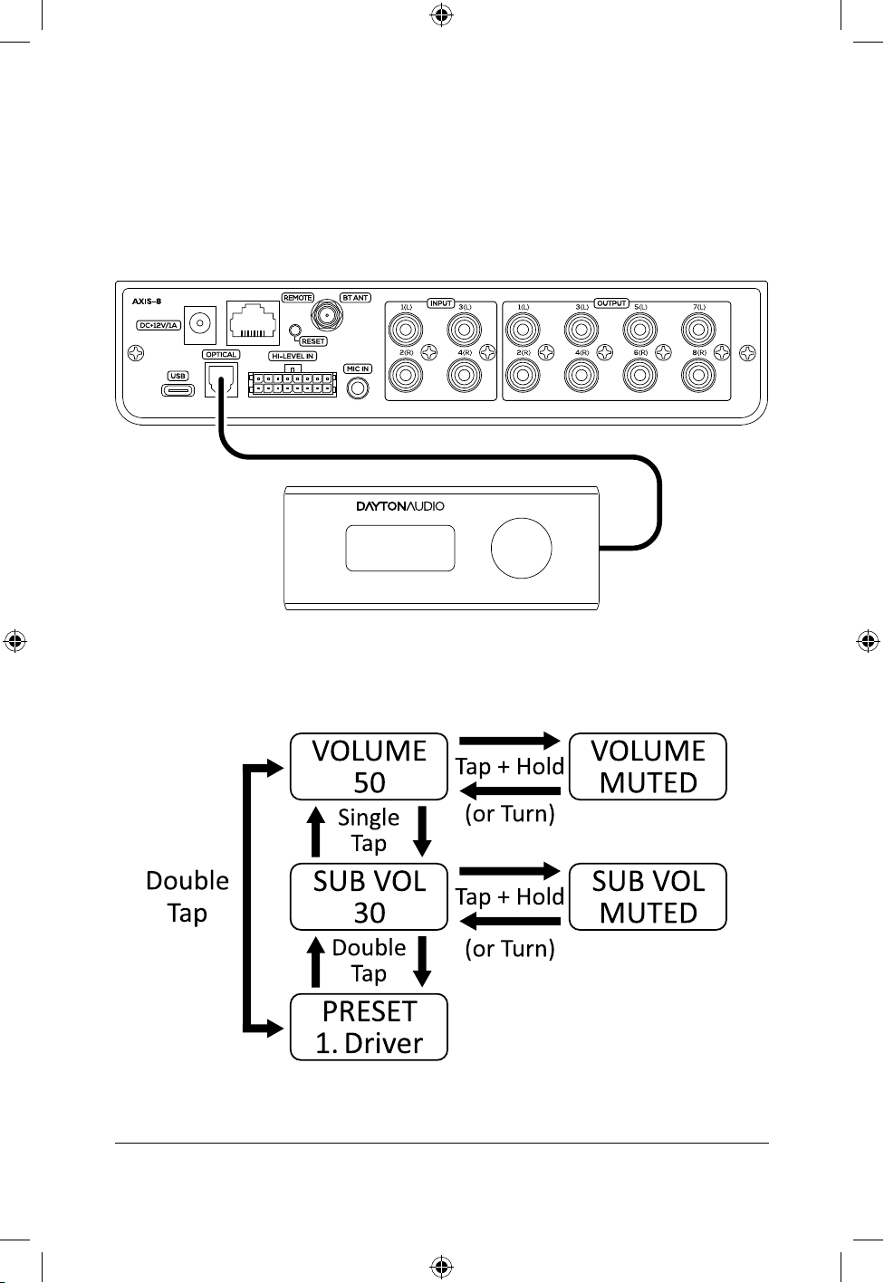
Wired Remote (Optional)
Connection
The optional AXIS-R wired remote can be connected to the AXIS-8 with the included 10-foot
ethernet cable. for custom lengths, standard ethernet cabling can be used to connect the
AXIS-R Remote.
Control
AXIS DSP
9
DAYTONAUDIO
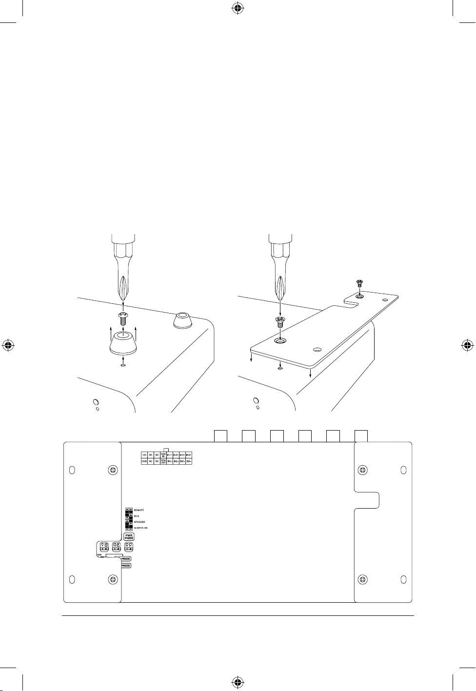
Using Mounting Brackets (Optional)
The optional mounting bracket kit allows the AXIS-8 to be securely installed in a variety of
locations, such as under seats or behind panels. The kit includes two mounting plates and four
mounting screws designed specically for the AXIS-8 chassis.
To install the mounting brackets:
1. Remove the rubber feet from the bottom of the AXIS-8.
2. Align the mounting plates with the threaded inserts on the underside of the unit.
3. Secure each plate using the provided screws.
4. Mount the unit to the desired surface.
Ensure the mounting surface is stable and allows adequate ventilation for the unit during operation.

AXIS DSP
10
DAYTONAUDIO
AXIS Control Software
Connectivity and System Requirements
AXIS Control is available for Windows PC, iOS, and Android platforms.
PC Connection
The Windows PC application is available for download from daytonaudio.com. The
application communicates with the AXIS device through a direct USB connection.
Minimum Requirements
•
Windows 10 or later
•
Available USB port
Mobile Device Connection
Mobile applications are available through the Apple App Store and Google Play Store. iOS
and Android applications communicate with the AXIS device using Bluetooth Low Energy
(BLE) wireless connectivity.
iOS Requirements Android Requirements
iOS 14 or later Android 10 or later
Bluetooth enabled device Bluetooth enabled device
The AXIS Control application communicates with the AXIS-8 using a dedicated Bluetooth
Low Energy (BLE) control connection. This connection is separate from Bluetooth audio
streaming and must be connected through the AXIS Control application.
To connect using Bluetooth BLE:
1. Enable Bluetooth on the mobile device.
2. Connect the included Bluetooth antenna to the AXIS-8.
3. Open the AXIS Control application.
4. At the top of the Home screen, select Connect to begin scanning for available devices.
5. Select the desired AXIS-8 device from the available device list.
6. Wait for the application to establish the BLE control connection.
Once connected, AXIS Control will allow wireless conguration and control of the AXIS-8.
IMPORTANT: Do not connect to the AXIS-8 simultaneously using both the mobile application
and the Windows PC application. Only one control connection should be active at a time.
NOTE: Bluetooth audio pairing and Bluetooth control connection are independent functions
and may appear as separate connections on the mobile device.
NOTE: If the AXIS-8 does not appear during device scanning, verify the device is powered
on and within Bluetooth operating range. Make sure the antenna is securely connected to
the AXIS-8.
AXIS DSP
11
DAYTONAUDIO
Setup Wizard
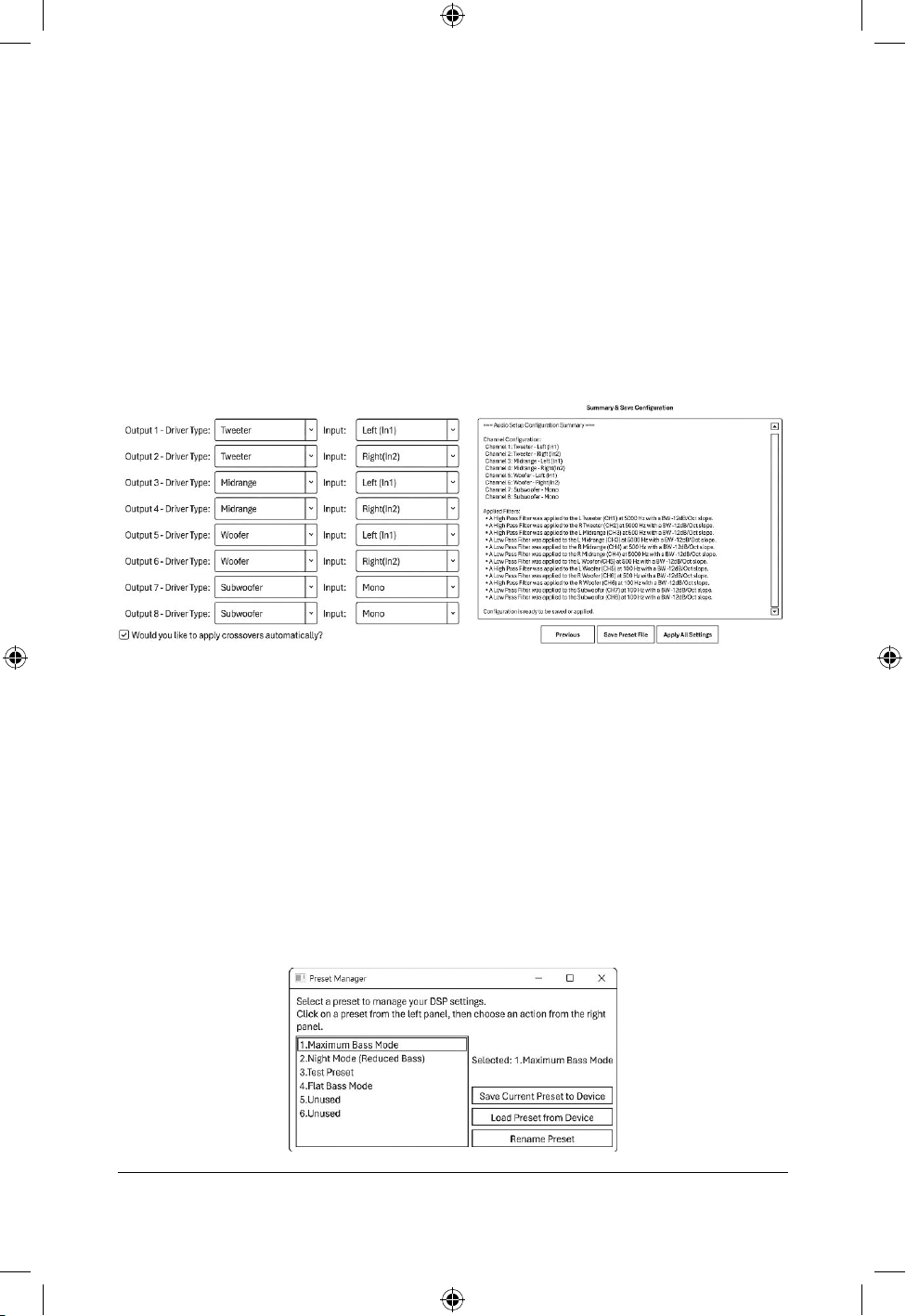
Jumpstart your workow with the AXIS setup wizard by eliminating tedious project
conguration. Simply specify the drivers connected to each AXIS-8 output and answer a few
simple questions. The wizard automatically routes inputs, sets groups, calculates crossovers,
and generates custom channel names based. This delivers a working prototype in seconds—
serving as an intuitive, hands-on learning tool for DSP beginners and a time-saving baseline
for advanced users.
To use the setup wizard, rst carefully follow the previous sections of this guide to connect
external ampliers and speakers and prepare your device for usage. Once the hardware is
ready, connect to either the mobile app or PC software and enter the “Setup Wizard” page.
The wizard will rst outline some basic instructions and then ask a series of questions. After
these prompts, the wizard will summarize all the conguration it intends on doing in a written
form. Conrm this conguration, and the AXIS-8 will automatically set itself up.
Saving Presets
The AXIS-8 is able to store up to 6 custom preset congurations to the device itself that can
be recalled using the wired remote, the PC software, or the mobile apps. These presets
can have custom names and be used for a variety of purposes, such as easy A/B testing,
optimizing dierent listening positions in a car or theater, or even switching to a night mode
that reduces bass levels.
The current conguration of the AXIS-8 can be saved as a preset at any time by entering the
preset manager menu, selecting the desired preset slot, and pressing save preset. This will
overwrite any previous settings saved into that slot. Any conguration changes made after
pressing save will not be automatically saved to this preset. To update the preset after making
changes, enter the preset manager and press save preset again.

AXIS DSP
12
DAYTONAUDIO
Factory Reset
When performing a factory reset, the AXIS-8 will return all settings to default values, erasing
all customization and conguration, including stored presets and Bluetooth connections.
Via Button
Hold the ‘reset’ button on the back of the device for 10 seconds, and the device will
automatically factory reset. Wait a few moments before resuming usage of the device.
Via Software
A factory reset can be performed through the AXIS Control application by navigating to
Settings > Factory Reset. Performing a factory reset will restore the AXIS device to its default
settings and erase all user conguration data.
Firmware Update
Firmware updates for AXIS devices are performed using the AXIS Control Windows PC
application and a direct USB connection between the PC and the AXIS device.
Firmware updates are not supported through Bluetooth wireless connectivity. Mobile iOS and
Android applications cannot perform rmware updates.
To update rmware:
1. Download and install the latest version of AXIS Control from daytonaudio.com
2. Connect the AXIS device to the PC using a USB cable.
3. Launch the AXIS Control application.
4. Follow the on-screen prompts to complete the rmware update process.
IMPORTANT: Do not disconnect USB power or close the AXIS Control application during the
rmware update process. Interrupting the update may cause improper device operation.
NOTE: It is recommended to use the latest available version of AXIS Control before
performing a rmware update.
AXIS DSP
13
DAYTONAUDIO
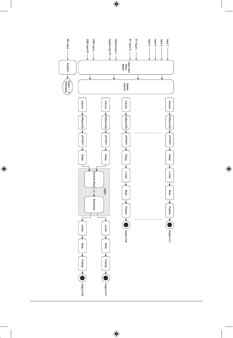
Block Diagram
AXIS DSP
14
DAYTONAUDIO
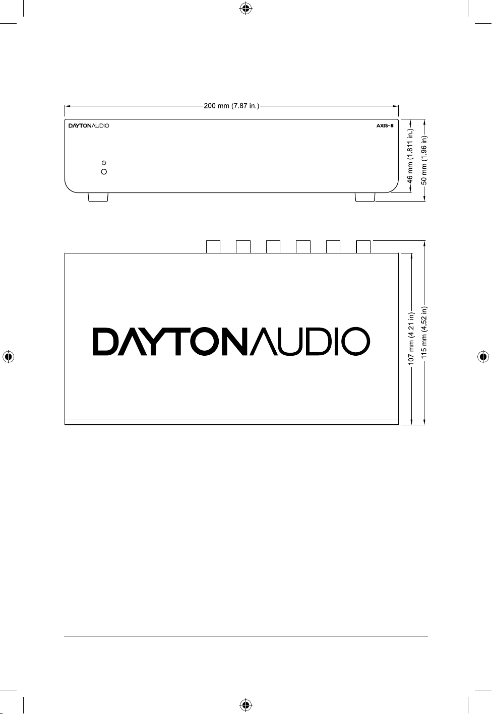
Dimensional Drawings
AXIS DSP
15
DAYTONAUDIO
Wiring Harness
AXIS DSP
16
DAYTONAUDIO
Troubleshooting
Problem Cause Solution
AXIS-8 does not power on No power connection or
blown fuse
Verify power and ground connections are
secure. Check inline fuse and vehicle fuse
panel.
Remote turn-on signal not
present
Verify +12V remote turn-on signal from the
source unit or amplier.
Wake from standby criteria
not met
Check the power mode setting. If using RCA
or Speaker mode, try increasing the signal
volume going into the AXIS-8.
LED is not lighting up, but the
device is powered on
The AXIS-8’s LED can be turned on and o
with a switch on the bottom of the unit.
No audio output from one
or more channels
Output muted or incorrect
routing conguration
Verify output channels are enabled and
conrm source routing and crossover settings.
Incorrect input source selected Verify the correct input source is selected
within AXIS Control.
AXIS Control app cannot
nd AXIS-8
Antenna not connected The AXIS-8 requires attaching the included
antenna for Bluetooth control and streaming.
Make sure this antenna is securly screwed into
the rear of the AXIS-8.
BLE connection not active or
device out of range
Verify the AXIS-8 is powered on and within
Bluetooth range, then rescan for devices.
Bluetooth disabled on mobile
device
Enable Bluetooth on the mobile device and
restart the AXIS Control application.
Unable to connect to the
AXIS PC application
USB cable issue Some USB cables cannot transfer data and
are only wired to transfer power. Use a known
data capable USB.
AXIS-8 is not powered AXIS Control requires the AXIS-8 to be on.
Changes made in AXIS
Control are not audible
Device not connected Check that the AXIS-8 shows as connected in
the top of the application.
Incorrect Connections Check that the RCA output of the AXIS-8 is
connected to the correct amplier and that it
is on. Check the speaker’s connection to the
amplier.
Bluetooth audio plays but
app will not connect
BLE control connection not
established
Open AXIS Control and connect through the
Connect menu within the application.
Distorted audio Input signal clipping or incorrect
gain settings
Reduce source volume and verify proper input
and output gain settings.
Unbalanced Voltage Levels If a stronger input voltage is provided to an
amplier than it can handle, the audio output
will distort. Switch the AXIS output mode to
HOME instead of CAR or reduce the AXIS
master volume. Optionally, increase the
amplier’s gain knob.
Excessive noise or engine
whine
Poor grounding or signal
interference
Verify proper chassis grounding and route
signal cables away from power wiring. Follow
proper installation standards.
Faulty Audio Amplier Bypass the AXIS-8 to determine if the noise
source is the amplier or audio source.
Mobile app disconnects
unexpectedly
Weak Bluetooth signal or
wireless interference
Move the mobile device closer to the AXIS-8
and minimize interference sources.
AXIS DSP
17
DAYTONAUDIO
Specications
Frequency Response 5 Hz - 22 KHz
Signal-to-noise Ratio 103dB
THD+N 0.008%
Sampling Rate 48 KHz
DSP Processing ADSP-21479 SHARC + ADAU1701 SigmaDSP
DSP Processing Resolution 24-bit
Input-to-Output Latency
Memory Presets 6
Line Level 4x RCA
Line Input Impedance
Hi Level 4x via wiring harness
Maximum Line Level Input Voltage 2.1V, 3.8V, 5V Modes
Maximum Speaker Level Input Voltage 40V RMS (Single Ended) 80V RMS (Dierential)
Digital Inputs SPDIF LPCM (up to 48 kHz 16 Bit)
PC-USB 16 Bit, 48KHz
Bluetooth 5.0
Line Level 8x RCA
Maximum Output Voltage 2V (Home), 5V (Car)
Output Impedance
Auto On On/ Auto
Maximum Time Delay 10 ms per channel
Bass Enhancement Superbass, Dynamic Bass
Power Requirements 12 VDC 1A
Standby Power Consumption 0.5 Watts
Auto-On voltage 4 mV
Dimensions (each)
W x H x D
7-7/8 x 4-1/4 x 2 in.
(200 x 107 x 50 mm)
Weight 1.61 lbs. (0.731 kg.)

daytonaudio.com
tel + 937.743.8248
705 Pleasant Valley Dr.
Springboro, OH 45066
USA
5-Year Limited Warranty
See daytonaudio.com for details
Dayton Audio
®
Last Revised: 5/14/2026