Page 1
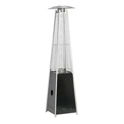
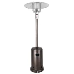
48,000 BTU Propane Outdoor Patio Heater
Item# 13533
Model# 2595270
Questions, problems, missing parts? Before returning to your retailer,
call our customer service department at 1-877-447-4768,
8:00 a.m. - 4:30 p.m., CST, Monday-Friday or email us at
Page 2
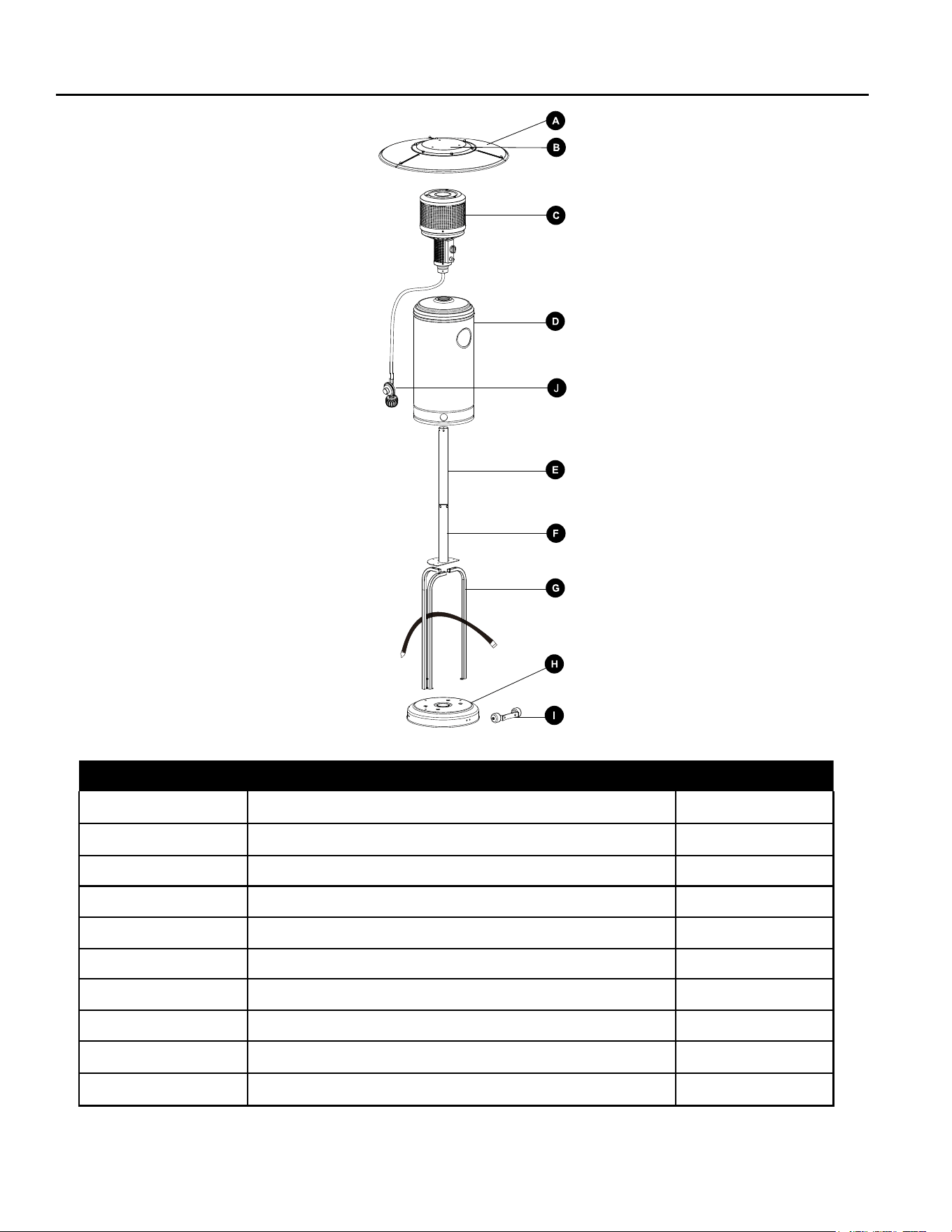
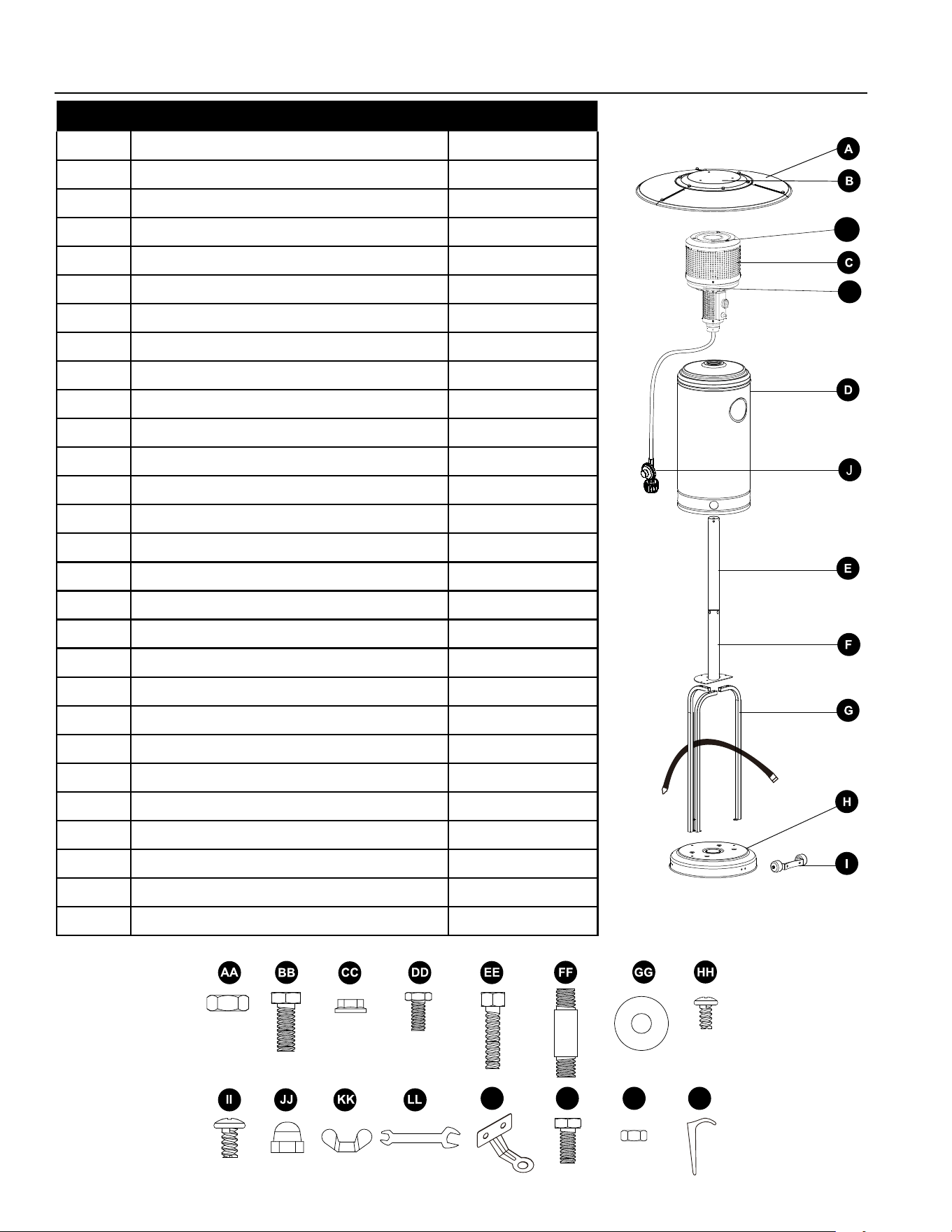
PACKAGE CONTENTS
Item Description Qty
A Reector Panel 3
B Center Reector 1
C Burner Assembly 1
D Tank Housing 1
E Upper Post 1
F Lower Post 1
G Support Bracket 3
H Base 1
I Wheel Assembly 1
J Regulator 1
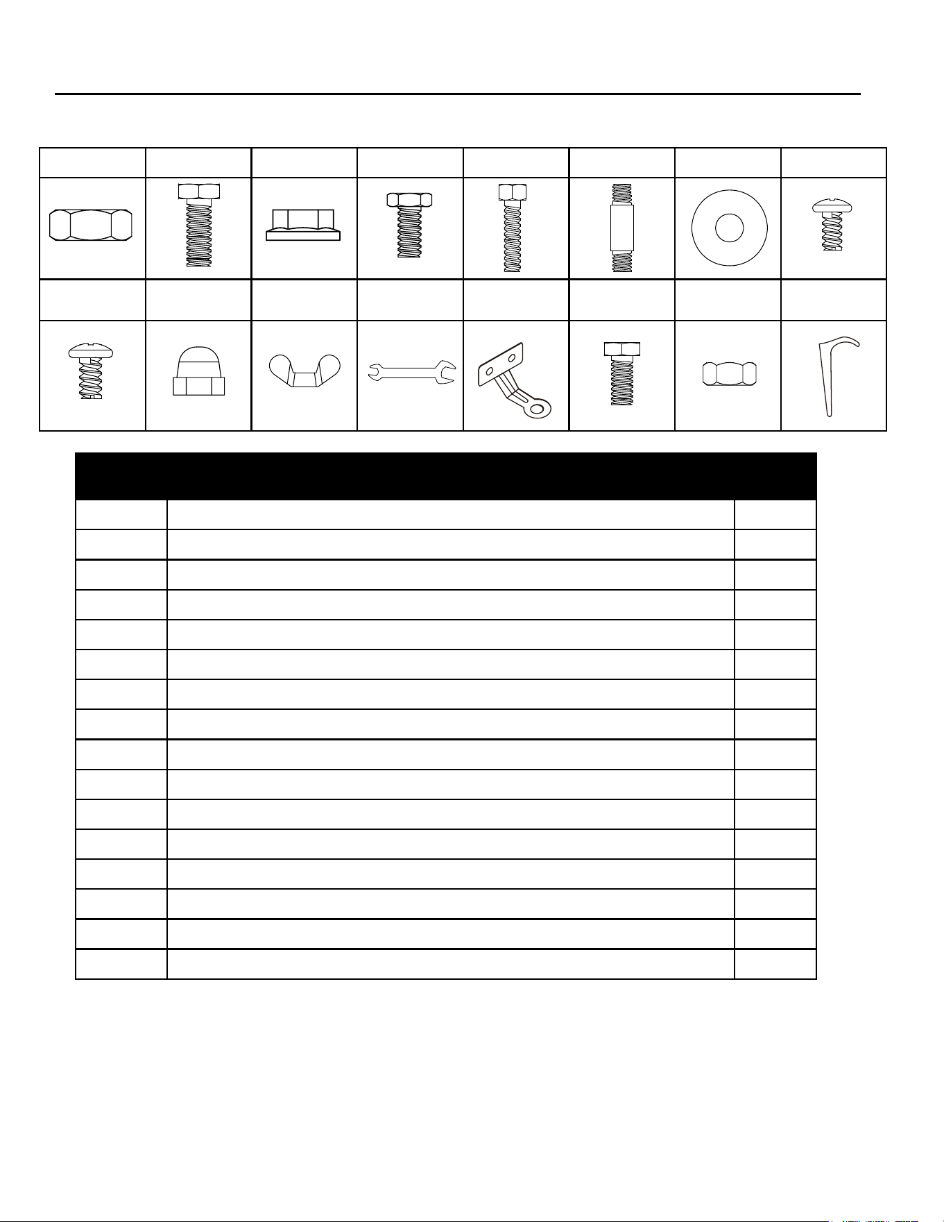
HARDWARE
Item Description Qty
AA M8 NUT (packed with part 1) 2
BB Bolt M8x16 (2 pcs packed with part 1) 5
CC M6 Flange Nut 6
DD Bolt M6x10 (pre-assembled on part C) 4
EE Bolt M6x30 6
FF Reector Spacer 3
GG Washer 9
HH Screw M5 (pre-assembled on part F) 2
II Screw M6x10 9
JJ Cap Nut 9
KK Wing Nut 3
LL Wrench 1
MM Anchoring Arm 3
NN Bolt M6x10 6
OO M6 Nut 6
PP Anchor 3
Before beginning assembly of product, make sure all parts are present. Compare parts with package
contents list and hardware contents list. If any part appears missing or damaged, don’t use this
product and call customer service immediately.
Tools Required for Assembly: Wrench (included) and Phillips Screwdriver (Not Included)
AA BB CC DD EE FF GG HH
II JJ KK LL MM NN OO PP
Page 3

Page 4
SAFETY INFORMATION
WARNING
Before you assemble or operate this unit, please carefully read this entire manual. Failure to do so
may result in a re, explosion, injury or death.
• The installation of this unit must adhere to local codes or Propane Storage and Handling Code,
CSA B149.2.
• THIS UNIT IS INTENDED FOR OUTDOOR USE ONLY! This product shall be used outdoors, in a
ventilated space and shall not be used in any enclosed area.
• This unit is to be used with propane gas only! (sold separately)
• Do not attach a remote gas supply to this unit.
• Only use propane gas for this unit.
• This unit is not intended for natural gas.
• Converting this unit to natural gas is dangerous and not recommended. The conversion of this
unit will void the manufacturer warranty.
• Do not use any solid fuel or charcoal for this unit.
• If the propane gas tank is leaking gas, you may see or smell it, or hear a hiss. Do the following:
1. Disconnect the propane gas tank. 2. Do not attempt to x the problem yourself. 3. Contact
your gas supplier or re department for help.
• Applying too much propane may result in gas pooling and will not burn. Allow fresh air into the
unit so that the remaining gas may escape.
• Do not use a ame to check for gas leaks.
• Manifold pressure: 11 in w.c. (2.74kPa).
• Use propane tanks with the following dimensions: diameter 12 in, height 18 in. - capacity 20 lbs
• You must use a propane tank that has a collar to protect the gas valve.
• DO NOT ll tank over 80 percent full.
• The tank system must be set up for vapor withdrawal.
• Discontinue use if any part of the propane tank is damaged. Rust and dents may be hazardous
and should be inspected by a gas supplier.
• Do not burn anything other than the provided materials for this patio heater.
• Do not operate unit until all parts are fully assembled.
• Do not paint or color any part of this heating unit.
• Unit may be hot while in use, do not attempt to move it while in use.
• Never leave this heating unit unattended while in use.
• This unit is not intended for cooking.
• Keep any ammable items away.
• Keep a safe distance to avoid burning skin or clothing.
• Do not sit or rest hands or feet on this heating unit.
• Never place hands or ngers on upper portion of this unit while in use.
• Keep all electrical cords and fuel supply hose away from heated surfaces.
• Combustible material should not be within 48 inches of the top of the unit, or within 48 inches
around the entire unit.
• Combustible material should not be within 48 inches of the top of the unit, or within 48 inches
around the entire unit.
• Keep the appliance area clear and free from combustible material, gasoline and other ammable
vapors and liquids.

SAFETY INFORMATION
• If the ame goes out while burning, turn the gas valve o. Wait 5 minutes before repeating the
initial lighting procedure. Once you have a ame started, hold down the control knob for 1 minute
• Do not add water into the unit.
• Do not operate unit if any part has been under water. Call a service technician to replace any
damaged parts should this occur.
• Do not disconnect any part while unit is in use.
• Do not store a spare propane tank under or near this appliance.
• If the heating unit is indoors, detach the propane tank and leave outdoors.
• Do not operate on a boat or vehicle. This unit must be used on a at surface and outdoors ONLY.
• Always remove protective cover before operating (if applicable).
• Check for leaks after not using the unit for long periods of time.
• Children should never operate this unit. Children must be supervised while near this unit.
• Keep gas tank at least 5 feet away from unit when lit. (if external tank)
• The maximum gas supply: 250psi; Min. gas supply:10 psi.
• Allinstallationandrepairshouldbedonebyaqualiedprofessional.Thisunitshouldbe
inspected annually and cleaned regularly.
• Inspect all elements of this heating unit before each use. If there is damage, the burner must be
replaced
• Be aware of the hazards of high temperatures and stay away from the unit to avoid any burns or
injury.
• The gas supply tank should be constructed and marked in accordance with the specications for
the LP-gas cylinders of the U.S. Department of Transportation (DOT) or CSA B339;
• The propane gas tank must have a listed overling prevention device and a QCCI or Type I,
(CGA791) propane gas tank connection.
• This heating appliance should not be used on plastic or articial wood decks.
• Childrenandadultsshouldbealertedtothehazardsofhighsurfacetemperaturesand
should stay away to avoid burns or clothing ignition.
• Youngchildrenshouldbecarefullysupervisedwhentheyareintheareaoftheheater.
• Clothingorotherammablematerialsshouldnotbehungfromtheheater,orplacedonor
near the heater.
• Anyguardorotherprotectivedeviceremovedforservicingtheapplianceshallbereplaced
prior to operating the heater.
• Installationandrepairshouldbedonebyaqualiedserviceperson.Theheatershouldbe
inspectedbeforeuseandatleastannuallybyaqualiedserviceperson.Morefrequent
cleaning may be required as necessary. It is imperative that the control compartment,
burnersandcirculatingairpassagewaysoftheheaterbekeptclean.
• Storage of an appliance indoors is permissible only if the cylinder is disconnected and removed
from the appliance. A cylinder must be stored outdoors in a well-ventilated area out of the reach
of children. A disconnected cylinder must have dust caps tightly installed and must not be stored
in a building, garage or any other enclosed area.
• Place the dust cap on the cylinder valve outlet whenever the cylinder is not in use. Only install the
type of dust cap on the cylinder valve that is provided with the cylinder valve. Other types of caps
or plugs may result in leakage of propane.
• Installation of this appliance at altitudes above 2000 ft (610 m) shall be in accordance with local
codes, or in the absence of local codes, ANSI Z223.1/NFPA 54 or CSA B149.1.
• Appliance may shut down in windy conditions in excess of 3 miles per hour (4.83 kilometers per
hour).
Page 5
Page 6
SAFETY INFORMATION
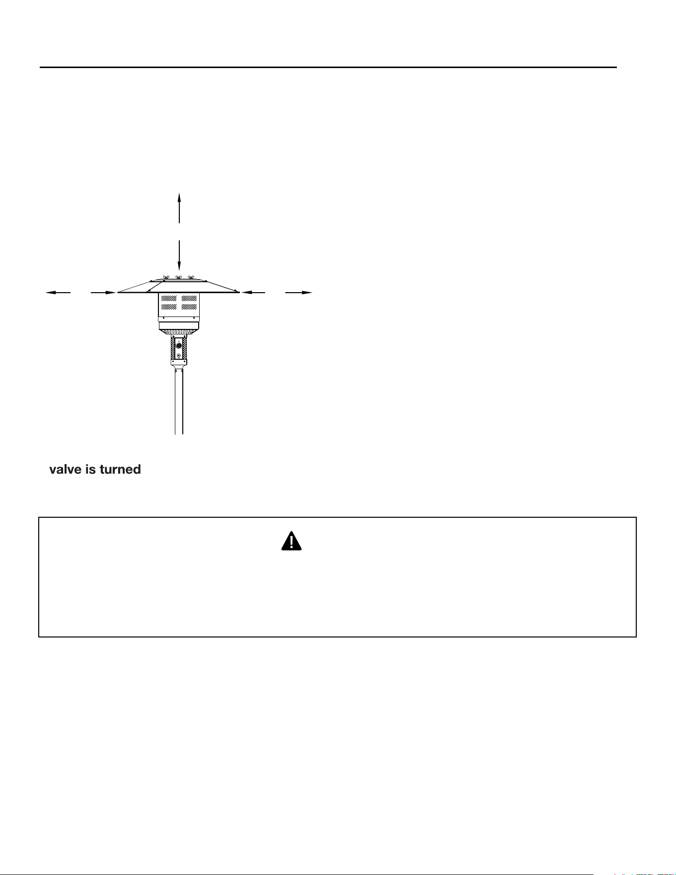
48"
48"
48"
BE CAREFUL: WHEN CERTAIN MATERIALS OR
ITEMS ARE STORED ABOVE, BESIDE OR UNDER
THIS HEATER WHILE IN USE, THEY WILL BE
SUBJECT TO RADIANT HEAT AND COULD BE
SERIOUSLY DAMAGED.
Combustible materials should not be within
inches of the top of the unit, or within inches
around the entire unit.
48
48
OFF’ before assembling. Do NOT attempt to assemble without proper tools.
NOTE: You must follow all steps to properly assemble this heating item. Make sure the gas
Only use the regulator and hose assembly provided with this unit. Replacement parts must be
supplied directly by manufacturer.
Inspect the burner before use of this unit. If the burner shows any kind of damage, do not operate
the appliance. For assistance with repair or replacement of the burner or any other parts, call
manufacturer at 1.877.447.4768.
WARNING
FUELS USED IN LIQUEFIED PROPANE GAS APPLIANCES,AND THE PRODUCTS OF
COMBUSTION OF SUCH FUELS, CAN EXPOSE YOU TO CHEMICALS INCLUDING BENZENE,
WHICH IS KNOWN TO THE STATE OF CALIFORNIA TO CAUSE CANCER AND CAUSE BIRTH
DEFECTS OR OTHER REPRODUCTIVE HARM.
Formoreinformationgoto:www.P65Warnings.ca.gov.
Page 7
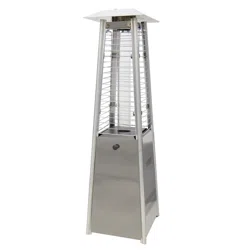
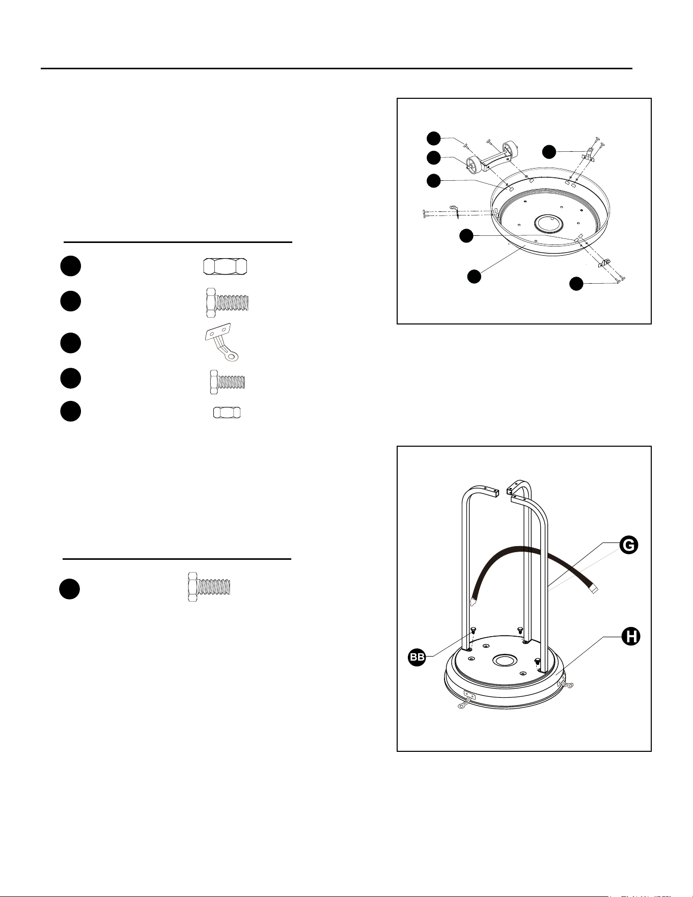
ASSEMBLY INSTRUCTIONS
1. Turn the base upside down, then attach wheel
assembly (I) to base (H) using 2pcs M8 nuts (AA)
and 2pcs bolts M8x16 (BB). Attach 3pcs anchoring
arm (MM) to base (H) using 6pcs M6 nuts (OO)
and 6pcs bolt M6x10 (NN). Be sure that the wheel
assembly is parallel to the base. Tighten bolts
securely.
AA
OO
NN
MM
BB
I
H
2. Attach 3 pcs support brackets (G) to base (H) using
3 pcs bolts M8x16 (BB).
Note: Keep the support bracket with belt in the
middle.
AA
BB
x 2
M8 nut
x 2
Bolt M8x16
Hardware Used
MM
x 3
Anchoring Arm
NN
x 6
Bolt M6x10
OO
x 6
M6 Nut
BB
x 3
Bolt M8x16
Hardware Used
ASSEMBLY INSTRUCTIONS
3. Attach lower post (F) to support brackets (G) using
6pcs bolts M6x30 (EE) and 6pcs M6 ange nuts
(CC). Tighten bolts securely.
4. Load tank housing onto post, slide tank housing
down.
5. Remove the 4 pcs preassembled bolts M6x10 (DD)
from the burner assembly (C). Insert the regulator (J)
from the top end of the upper post (E), then attach
the burner assembly (C) to upper post (E) using the
four bolts removed at the beginning of this step.
Tighten bolts securely.
F
J
CC
x 6
Hardware Used
EE
x 6
Bolt M6x30
M6 Flange nut
Hardware Used
x 4
Bolt M6x10
Page 8
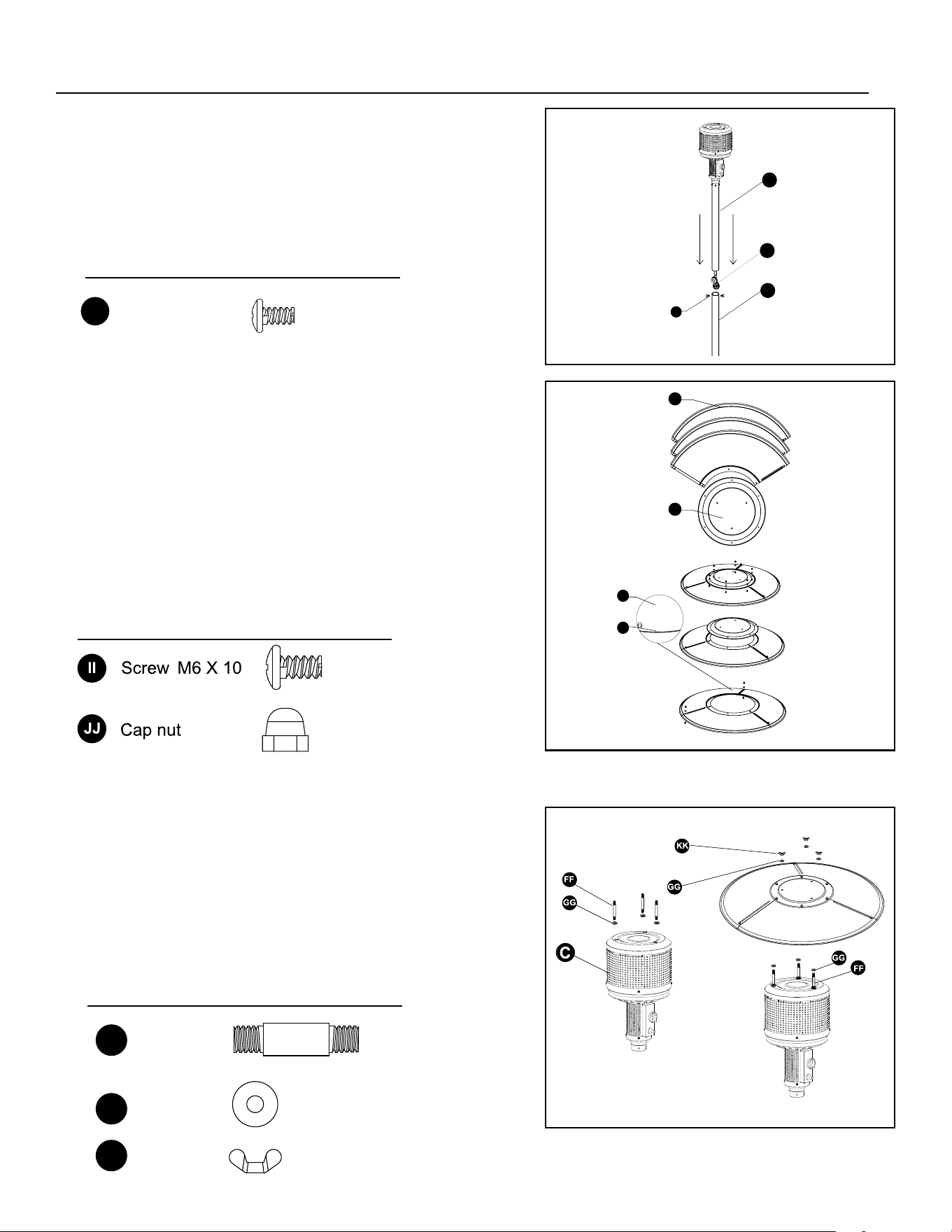
6. Remove the 2 preassembled screws M5 (HH)
from the lower post (F). Insert the regulator
(J) from the top end of the lower post (F).
Insert upper post (E) to lower post (F), then
tighten two posts using the 2 screws M5 (HH)
removed at the beginning of this step.
HH
F
E
J
ASSEMBLY INSTRUCTIONS
7. WARNING: Remove protective lm before
assembling.
Note: If necessary for proper alignment of reector
sections.
Attach 3 pcs reector panels (A) to center reector
(B) using 9 pcs Screws M6x10 (II) and 9 pcs cap
nuts (JJ). Fully tighten all of the screws.
8. Attach 3 pcs reector spacers (FF) and 3 pcs
washers (GG) to burner assembly (C) rstly.
Tighten the reector spacers. Slide 3pcs
washers (GG) over threaded end of spacer.
Attach the reector assembly to the top of
reector spacer (FF) using 3 pcs washers (GG)
and 3 pcs wing nuts (KK).
B
A
7-1
II
JJ
II
HH
x 2
Hardware Used
Screw
M5
x 9
x 9
Hardware Used
GG
KK
x 9
Washer
FF
Reflector
spacer
x 3
Wing nut
Hardware Used
x 3
Page 9
Page 10
PP
ASSEMBLY INSTRUCTIONS
9. Optional: Use the anchor (PP) to fasten the
product into the ground.
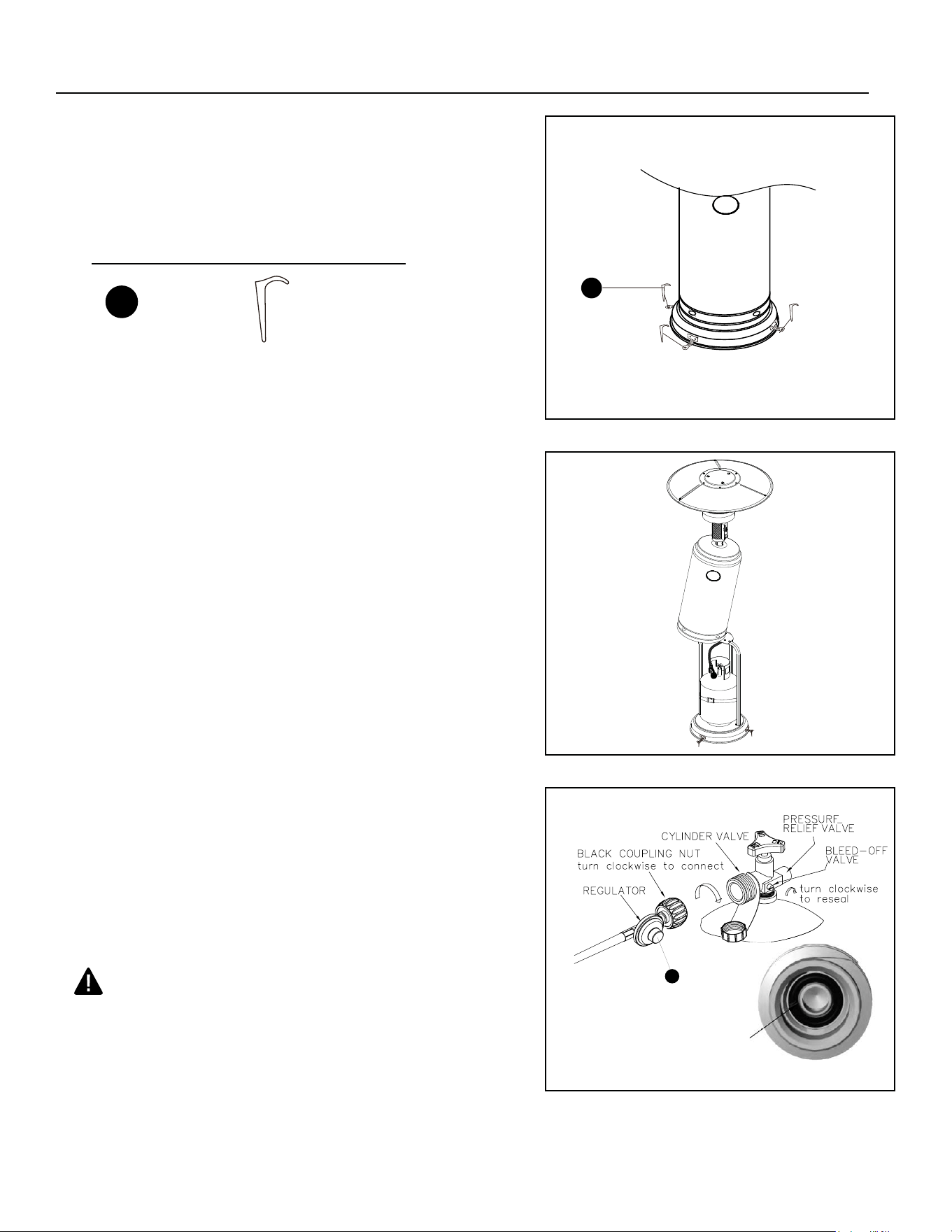
10. Place the propane gas tank (not included) on the
base. Tighten the belt to ensure the propane gas
tank is fully secure.
WARNING
Please inspect the O-ring in the propane tank
valve to ensure it is not worn before attaching
regulator. Worn rubber O-ring can cause leaks,
explosions and serious injury by propane tank.
J
RUBBER O-RING
PP
Anchor x 3
Hardware Used
11. Turn the cylinder valve on the tank clockwise
to close the propane tank. Attach the regulator
(J) to the cylinder valve by turning the regulator
coupling nut clockwise. Make sure it is fastened
securely and tighten connections by hand only.
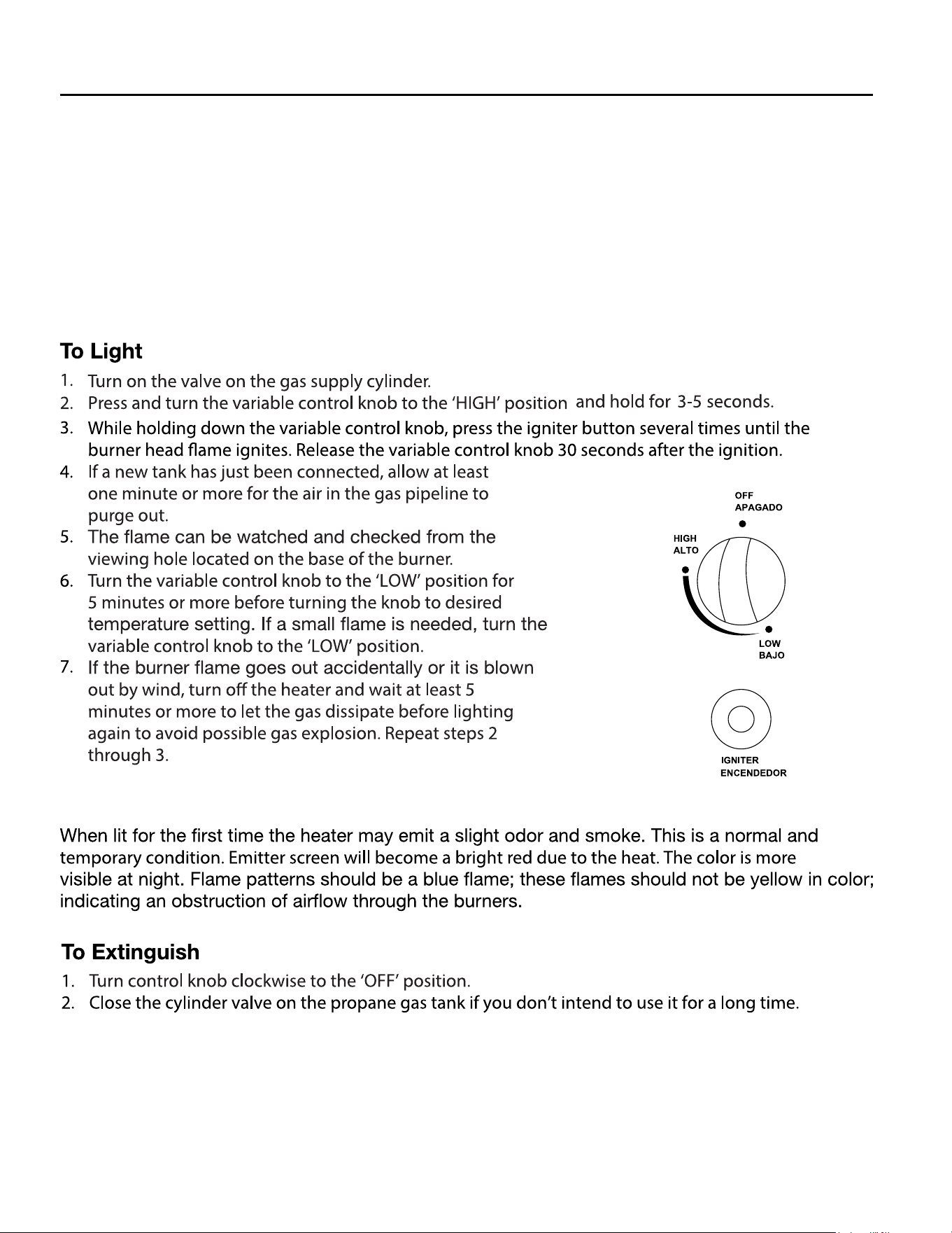
OPERATION
Before performing a leak test, be sure that no sparks can occur and you are in a spacious outdoor
area. Connect the propane gas tank to the regulator and turn the valve on the unit to the ‘OFF’
position. Brush a soap and water mixture on all connections. Turn the gas supply on; if bubbles
occur on any connection there may be a leak.Ifyousmellgasoraleakisdiscoveredturnthe
gasvalveo,disconnectpropanegastankanddonotusetheapplianceuntiltheleakis
repaired.
Do not use the heating unit without inspecting the gas hose. If there are signs of wear or abrasion
you must replace the hose (if applicable).
Page 11
Page 12
MAINTENANCE
CONTACT
If you have any questions or concerns, please contact manufacturer at the below resources:
Toll free phone 1-877-447-4768 | Monday - Friday, 8:00 am - 4: 30 pm CST
Email [email protected]
Website www.ghpgroupinc.com
WARRANTY
This product has a one-year warranty against manufacturing defects in workmanship, or materials.
The manufacturer warranty will be voided by, and manufacturer disclaims any responsibility for, the
following actions:
• Modication of the unit and/or components including the gas valve assembly.
• Use of any component part not manufactured or approved by Manufacturer.
• Use and installation other than what is listed in this manual.
Please contact the manufacturer for replacement parts.
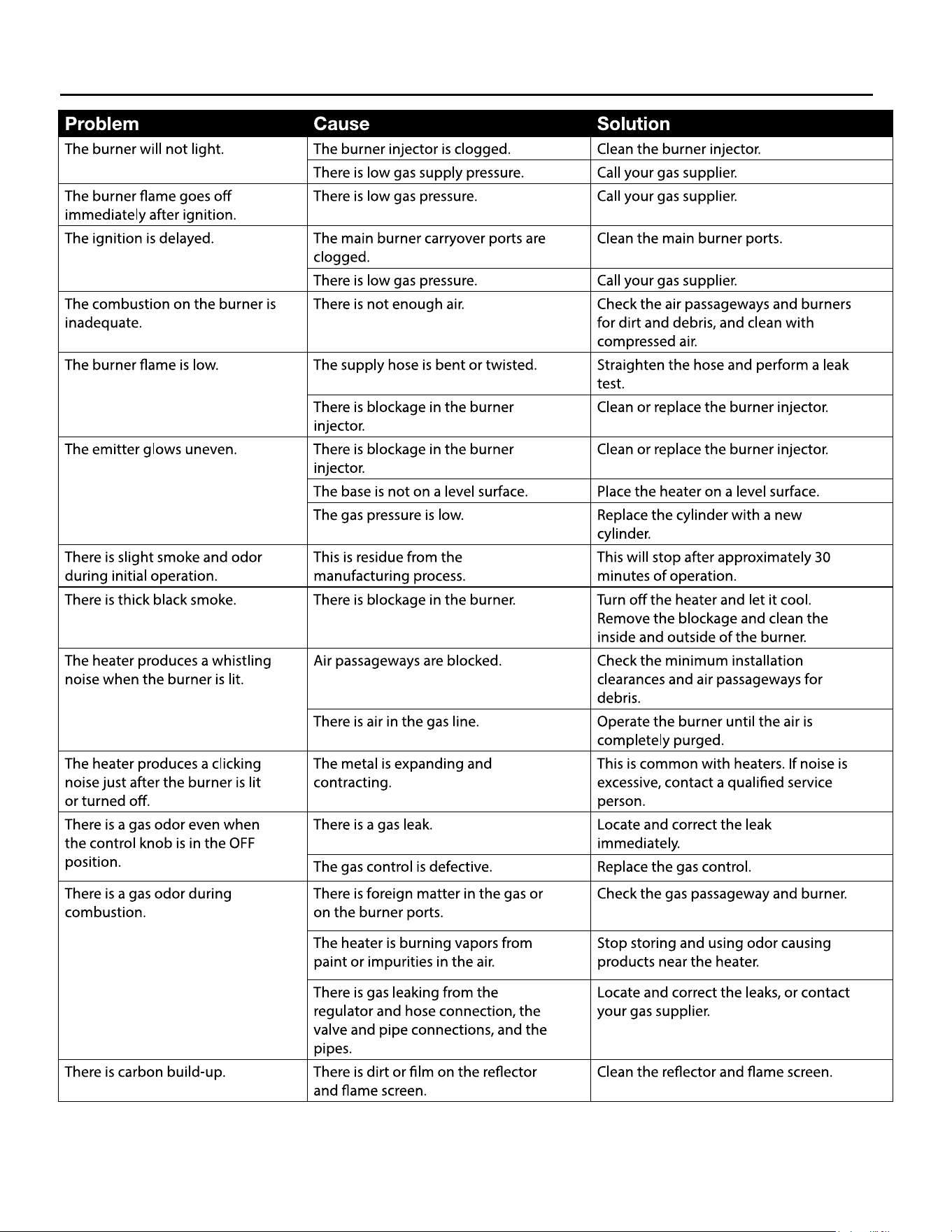
TROUBLESHOOTING
Page 13
Page 14
REPLACEMENT PARTS LIST
PART DESCRIPTION PART #
AA M8 Nut (packed with part I) 30-07-359-B
BB Bolt M8x16 (2 pcs packed with part I) 30-07-360-B
CC M6 Flange Nut 30-07-361-B
DD Bolt M6x10 (pre-assembled on part C) 30-07-362-B
EE Bolt M6x30 30-07-363-B
FF Reector Spacer 30-07-364-B
GG Washer 30-07-365-B
HH Screw M 5 (pre-assembled on part F) 30-07-366-B
II Screw M6x10 30-07-367-B
JJ Cap Nut 30-07-368-B
KK Wing Nut 30-07-369-B
LL Wrench 30-07-370-B
MM Anchoring Arm 30-07-371-B
NN Bolt M6x10 30-07-372-B
OO M6 Nut 30-07-373-B
PP Anchor 30-07-374-B
A Reector Panel 30-07-349-B
B Center Reector 30-07-350-B
C Burner Assembly (48k BTU) 30-01-947
D Tank Housing 30-07-352-B
E Upper Post 30-07-354-B
F Lower Post 30-07-355-B
G Support Bracket 30-07-356-B
H Base 30-07-357-B
I Wheel Assembly 30-07-358-B
J Regulator 30-07-353-B
K Thermocouple 30-01-948
L Gas Valve 30-01-949
MM NN OO PP
L
K