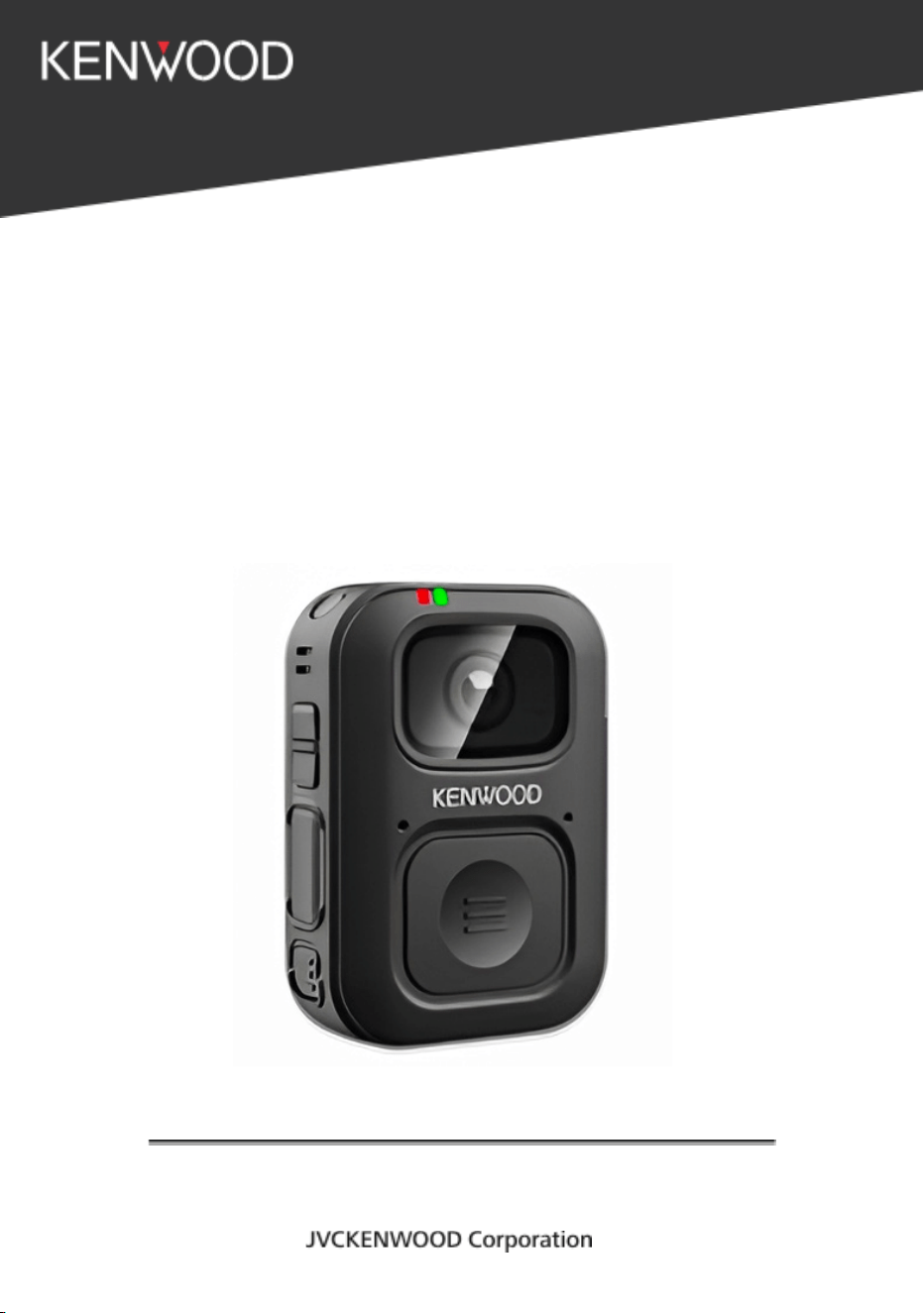
JVCJ-LITE &
JVCJ DOCK
BODY WORN CAMERA
USER MANUAL

TABLE OF CONTENTS
1. INTRODUCTION
2. PRODUCT OVERVIEW
2.1 Product Specification
3. INITIAL SETUP AND CONFIGURATION
4. GET TO KNOW YOUR CAMERA
4.1 Button Actions
4.2 Power ON the Device
4.3 Power OFF the Device
4.4 LCD MENU Icon and Description
4.4.1 Status Icons
4.4.2 Clock / Notification / Emergency Messages
4.5 LCD Settings Menu
4.6 Icons and Notifications
4.7 LED Indicator
4.8 Sound Indicators
4.9 Charging Instructions
4.9.1 Charging Using JVC Kenwood Docking Station
4.9.2 Charging Using Standard 5V USB Type-C Charger
4.9.3 Charging Precautions
4.10 How to Attach the Camera
4.11 Accessing Web UI
4.11.1 Web UI Guide
4.11.2 Connect Device to new WIFI
4.11.3 How to Start Recording
4.11.4 How to Start Live streaming
4.11.5 Thermal Limiter for video recording
4.11.6 Overwrite Feature

4.11.7 Using Push To Talk (PTT)
5. MAINTENANCE
5.1 Regular Cleaning and Maintenance
5.2 Storage Location and Temperature
5.3 Battery Care
5.4 Protect from Physical Damage
4.5 Firmware and Software Maintenance
5.6 Handling of Docking Station
5.7 Troubleshooting & Regular Maintenance
5.8 Important Warnings
6. SOFTWARE UPDATE
7. FAQ AND BASIC TROUBLESHOOTING
8. LITE Packaging Box
9. Dock Packaging Box

* SAFETY PRECAUTIONS AND CERTIFICATION
● This document serves as the User Manual for the Body Worn
Camera (BWC). It provides detailed instructions and information
required for the safe and effective operation of the device.
● The manual describes the camera’s features, controls, operating
procedures, indicators, and basic troubleshooting guidelines.
● The contents of this manual are intended to help users understand
the functionality of the Body Worn Camera and ensure proper
usage during daily operations.
● The information presented is based on the finalized product design
and is intended for end users, administrators, and support
personnel responsible for operating and maintaining the device.
1. INTRODUCTION
This document serves as the User Manual for the Body Worn Camera
(BWC). It provides detailed instructions and information required for the
safe and effective operation of the device.
The manual describes the camera’s features, controls, operating
procedures, indicators, and basic troubleshooting guidelines.
The contents of this manual are intended to help users understand the
functionality of the
Body Worn Camera and ensure proper usage during daily operations.
The information presented is based on the finalized product design
and is intended for end users, administrators, and support personnel
responsible for operating and maintaining the device.
2. PRODUCT OVERVIEW
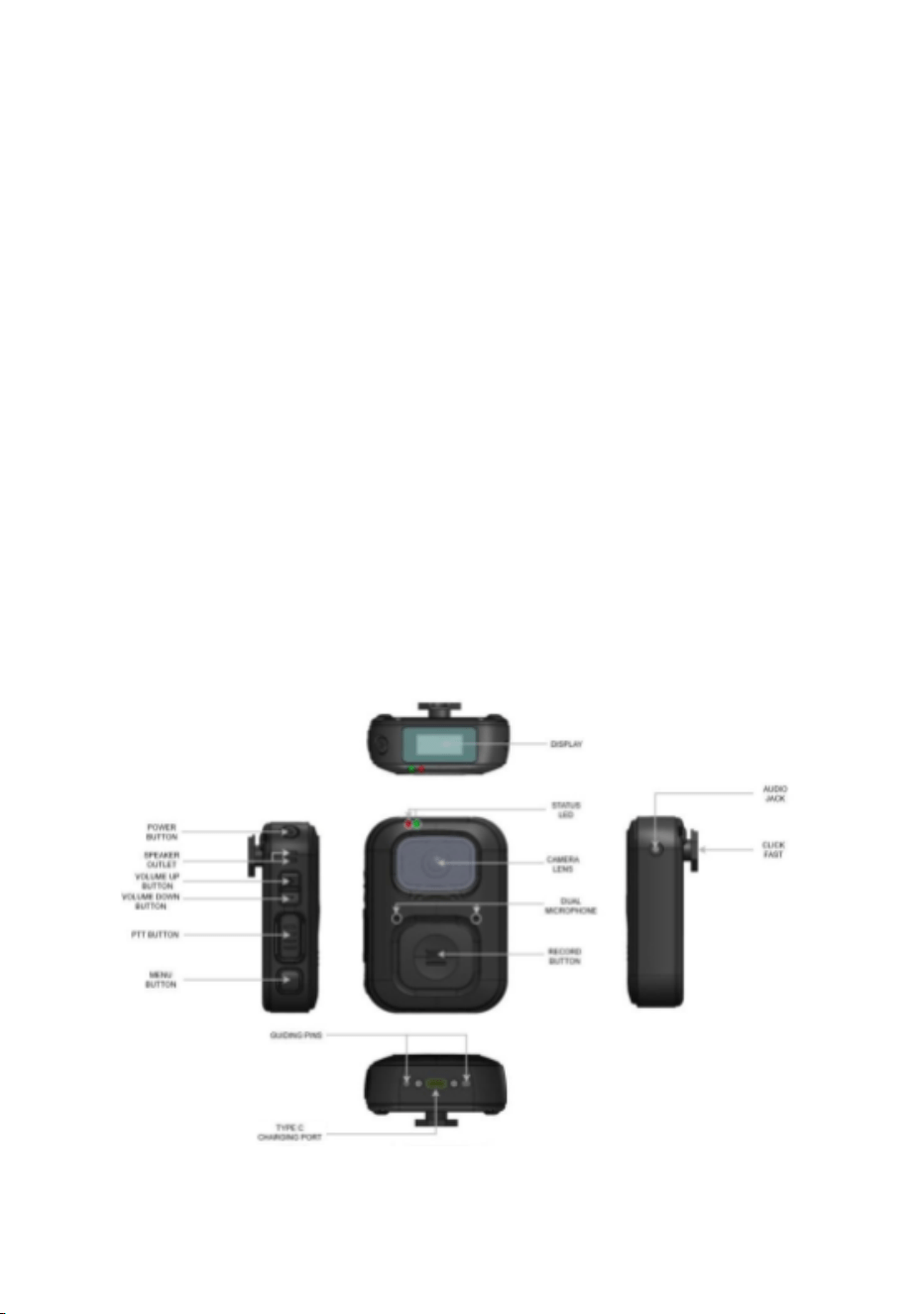
Figure 1. Multi-angle views of the device
2.1. Product Specification
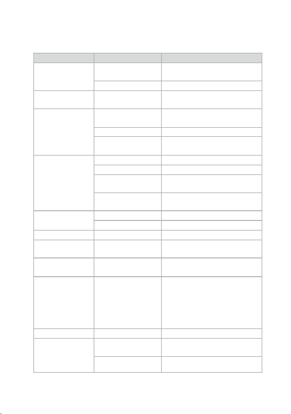
Category
Specification
Details/Description
Body
Dimension (LxWxT)
Approx. 91 x Approx. 66.3 x
Approx. 27.3 mm
Weight
Approx. 165 g
Ingress
Protection
Standard
IP54
Camera
Lens
M12 Mount, 139.1° (H), 79.8°
(V), 160.0° (D)
Image sensor
1920 × 1080, 30fps, 2MP
Video Recording
Format
H.264, H.265
Sound
Speaker
1W
MIC
MEMS, Digital
Audio Jack
3.5mm Audio Jack (Cellular
Std)
Audio Recording
Format
AAC
Memory &
Storage
Type
eMMC
Capacity
128GB
Display
Type
LCD
Battery
Type
Li-ion, 3.89V, 3600mAh,
14.01Wh
Communication
Wireless
connectivity
WiFi (2.4, 5GHz), Bluetooth
V5.2 + BLE
Positioning
GNSS Support
GPS (L1 C/A), Galileo
(E1B+E1C), QZSS (L1
C/A+L1SAIF), GLONASS
(L1OF), BeiDou
(B1I), SBAS (L1)
Interface
USB
USB 3.1
Power
Power Supply
Voltage
5V DC
Power
5W (max)
Consumption
Accelerometer
Built-in 3-axis accelerometer
Table 1. Technical Specifications
3. INITIAL SETUP AND CONFIGURATION
This section describes the initial set up and configuration activities
required to prepare the device for operation.
• Charging the Device
Device must be charged before first use.
Device can be charged via:
● Docking station
● USB Type-C charger
LED indication for charging
How to Boot-Up the Device:
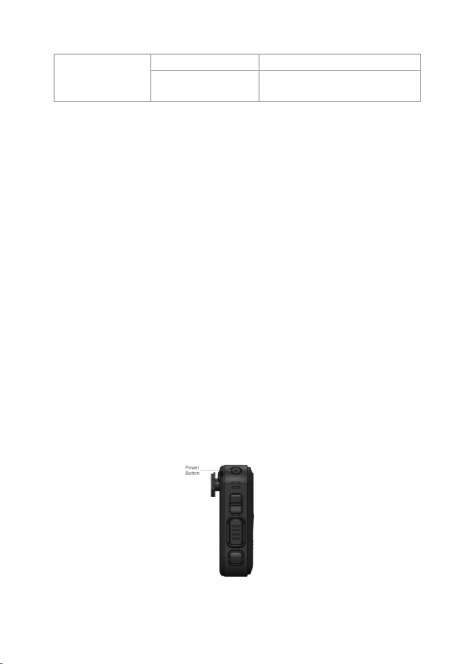
• Press and hold the Power button for less than 1 second to turn
ON the device.
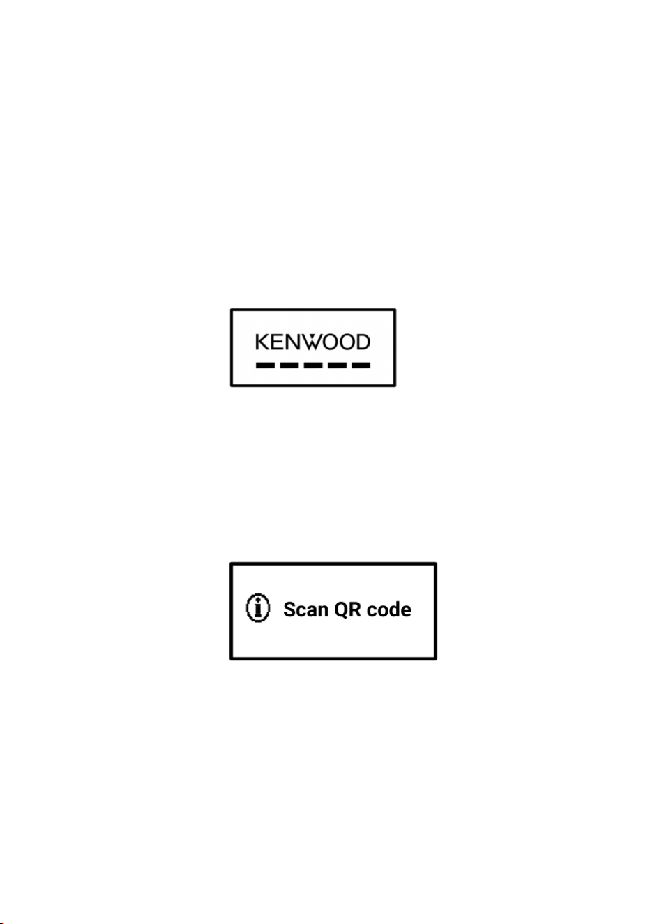
Figure 2. Device power button position
• The device will boot up and display the “KENWOOD” logo followed
by the Scrolling Lines on the LCD screen.
Figure 3. LCD UI loading screen
• After boot-up, the device requires Provisioning. If the device is not
yet provisioned, the LCD UI displays “Scan QR code”. Else, the home
screen will be displayed (Skip the remaining steps and move to the next
section).
Figure 4. LCD notification - Scan QR code
• To provision the device, present a QR code of any Wi-Fi network in
front of the camera.
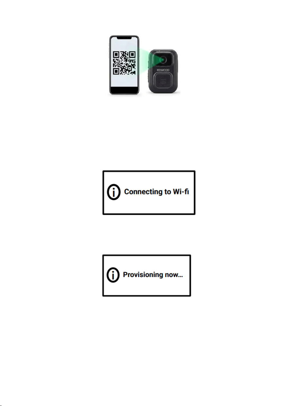
Figure 5. QR code scanning in action
• Once the QR code is successfully scanned:
◦ The device emits a beep sound indicating that the device is reading
the QR code.
◦ The device connects to the Wi-Fi network and accesses the internet.
Figure 6. LCD notification - Connecting to Wi-Fi
• Wait for a few seconds for the provisioning process to complete.
Figure 7. LCD notification - Provisioning Now
• Upon successful provisioning, the LCD UI displays a “Provisioned”
message.
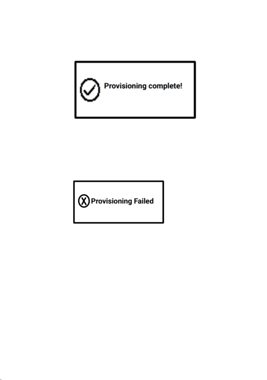
Figure 8. LCD notification - Provisioning completed
● If the provisioning got Failed the LCD UI will display as below
Figure 9. LCD notification - Provisioning Failed
4. GET TO KNOW YOUR CAMERA
4.1. Button Actions
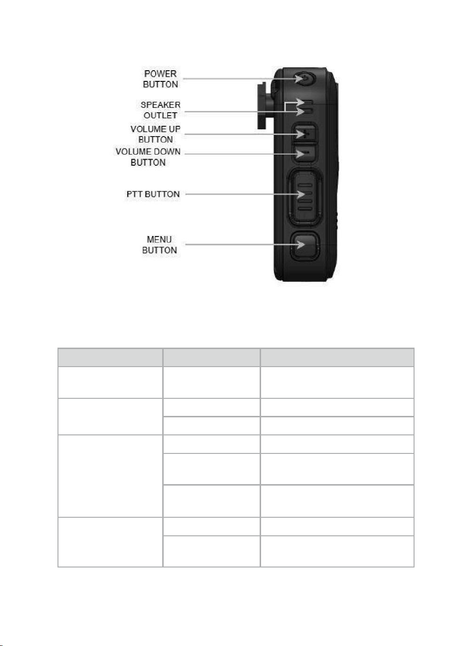
Figure 9. External button layout
Button
Instruction
Description
Power
Button
Long press once
Power ON / OFF the device
Record
Button
Short press once
Start video recording
Long press once
Stop video recording
Volume Up Button
Short press once
Increase volume by one level
Long press
Gradually increase volume to
maximum
-
Used for navigation in the
menu interface (move up)
Volume Down
Button
Short press once
Decrease volume by one level
Long press
Gradually decrease volume to
minimum (mute)
-
Used for navigation in the
menu interface (move down)
PTT (Push-to-Talk)
Button
Press and hold
Activates the Push-to-Talk
function. Hold the button while
speaking to transmit your
voice, and release it to stop
transmission
Menu Button
Short press once
Opens the main menu
interface for accessing device
settings and features.
Table 2: Buttons
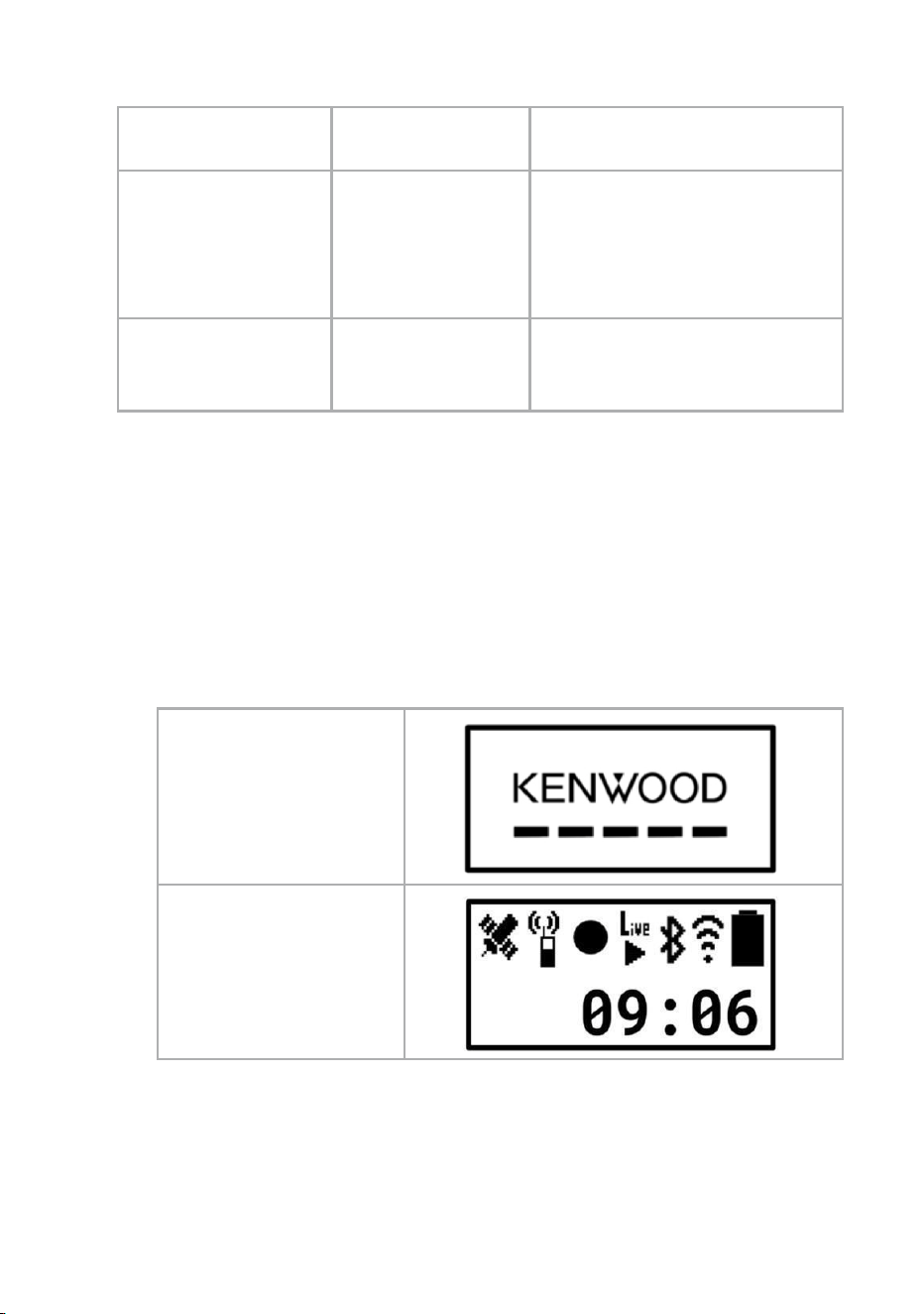
4.2. Power ON the Device
Press and hold the Power button for 1 second. Once the device starts
booting, the
“KENWOOD” Logo screen is displayed. Please wait until the Home
Screen appears.
• Boot Logo with scrolling lines, then
• Home Screen
1.Boot logo
2. Home Screen
Table 3. LCD Screen During Power-On
Note:
• If the device is powered OFF and a Type-C charger is connected,
the device will automatically power ON without pressing the power
button.
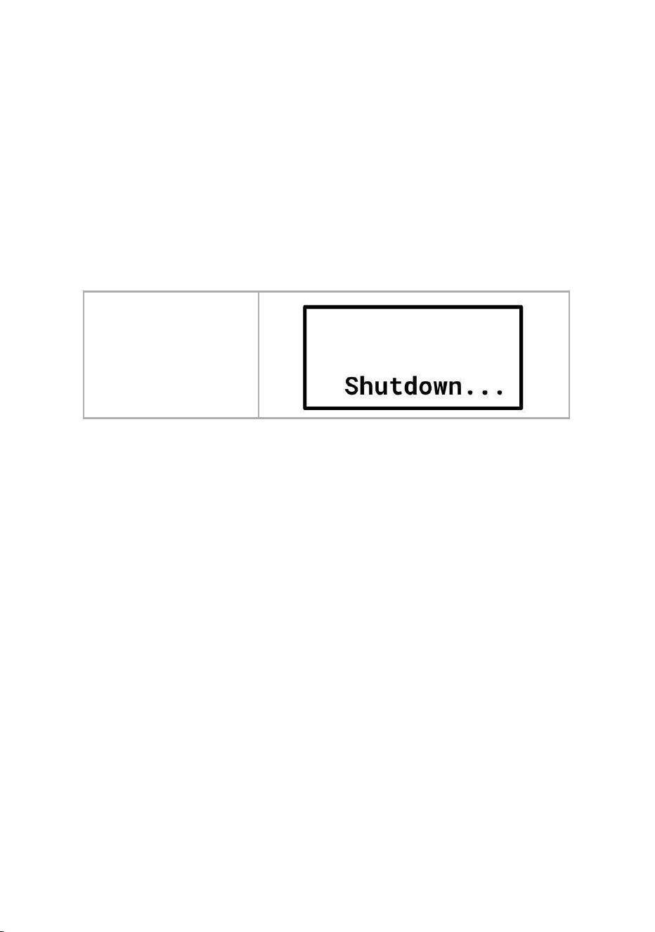
4.3. Power OFF the Device
Press and hold the power button for 2 seconds to power OFF the device.
1.Shutdown
Screen
Table 4. LCD screen During Power-OFF
Note:
• If the device is connected to a charger while attempting to shut
down, the device will shut down and then boot up instead of
remaining powered OFF.
• That is, when the charger is connected, the device cannot
remain in a powered-OFF state.
• If the device is shut down while charging, it will automatically boot
up.
4.4. LCD MENU Icon and Description
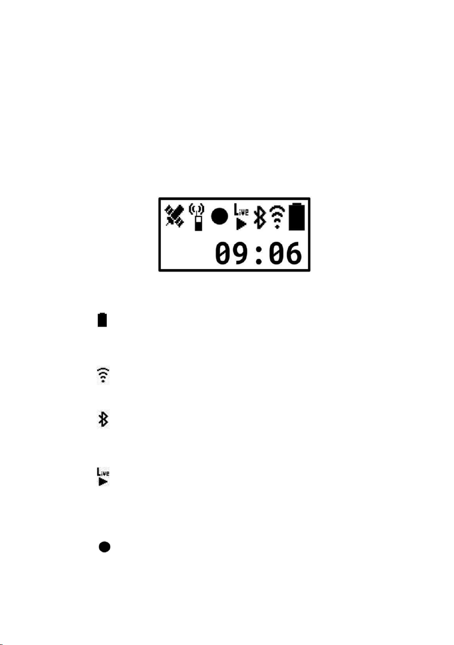
The device features an LCD interface that allows the user to navigate
menus, access device functions, and monitor status information.
This section provides a reference for all menu icons, their functions, and
descriptions to help users operate the device efficiently.
4.4.1 Status Icons
Figure 10. LCD UI home screen.
• Power Icon
The black area of the icon changes depending on the remaining
battery level.
• Wifi connecting icon
Indicate if your Wifi signal strength is low.
• Bluetooth connecting icon
The Bluetooth icon indicates the Bluetooth status (ON, OFF). The
headset icon indicates
• Live streaming icon
Turns on when recording is active. Live stream timer will also start
once recording is started. To start live streaming, please refer to the
section “How to Start Live streaming” of this document.
• Video Recording icon
Turns on when recording is active. The video timer will also start
once recording is started. To start recording, please refer to the
section “How to Start Recording” of this document.
• PTT Application icon
Turns on when the PTT application is active.
• GPS receiving icon Turns on when location is ON.
4.4.2 Clock / Notification / Emergency Messages
Figure 11. LCD UI clock position on home screen
The Clock is displayed in the lower half of the screen.
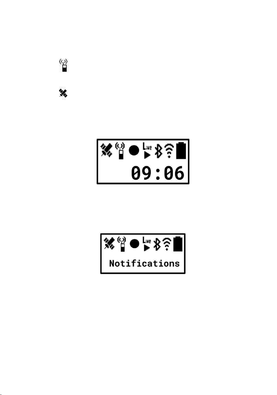
Figure 12. LCD UI notifications position on home screen
If there are notifications from the system, applications, MDM, etc., they will
be displayed in text in the lower half of the screen. If a new notification is
sent, the new one will be displayed.
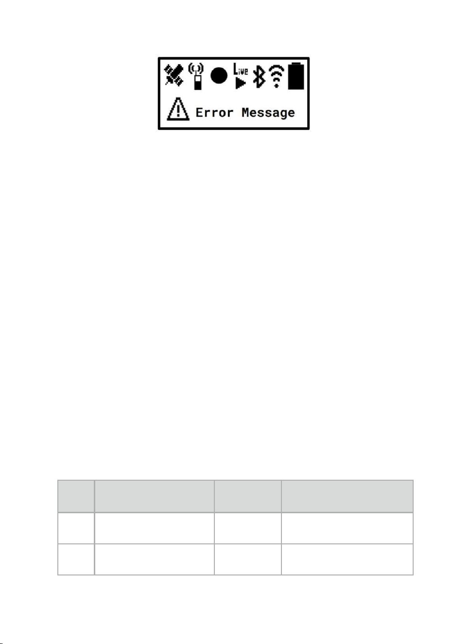
Figure 13. LCD UI error messages position on home screen
The lower display also shows when an emergency occurs. This is a
placeholder where actual notifications and messages will appear here.
4.5. LCD Settings Menu
The BWC Settings Menu provides a structured interface to configure and
customize your body worn camera (BWC) functions. The menu is
organized hierarchically, allowing users to navigate from general settings
to specific sub-settings and their corresponding options with ease.
Users can access the settings menu by pressing the Device Menu button.
Navigation through the menu is performed using the Volume Up and
Volume Down buttons. The currently highlighted option is indicated by an
arrow icon, which serves as a visual guide. Pressing the Menu button on
a highlighted setting either opens the corresponding sub-settings or
selects an option, depending on the context. Please refer to the below
table for more information.
SL
NO
Operation/Settings
Options
How to Navigate / Select
1
Wi-Fi
On, Off
Device Menu → Basic
Settings → Wi-Fi
2
Bluetooth
On, Off
Device Menu → Basic
Settings →Bluetooth

3
Scan and select
Bluetooth devices
Select
Device Menu → Basic
Settings → Select BT
Device → Scanning.... →
After scanning
completes, highlight the
desired device select and
pair.
4
Connect to already
paired Bluetooth
devices
Select
Device Menu → Basic
Settings → Paired Device
→ Highlight the desired
device and connect
5
Language
English,
French
Device Menu → Basic
Settings → Language
6
Enable and disable
Button press sound
On, Off
Device Menu → Basic
Settings →Button Press
Sound
7
Enable Electronic
image stabilization
On, Off
Device Menu → Camera
Settings →EIS Mode
8
Set streaming
Frame rate
30,15,10,5
Device Menu →
Streaming Settings
→Frame Rate
9
Set streaming video
format
H264,
H265,
MJPEG
Device Menu →
Streaming Settings
→Video Format
10
Set streaming
resolution
1920x 1080,
1280x 720,
854x480
Device Menu →
Streaming Settings →
Resolution
11
Set streaming
encryption
None,
RTSPS,
SRTP
Device Menu →
Streaming Settings →
Streaming Encryption

SL
NO
Operation/Settings
Options
How to Navigate /
Select
12
Set recording frame
rate
30, 15, 10,
5
Device Menu →
Recording Settings
→Frame Rate
13
Set recording video
format
H264, H265
Device Menu →
Recording Settings
→Video Format
14
Set Recording
resolution
1920x1080,
1280x720,
854x480
Device Menu →
Recording Settings →
Resolution
15
Pre Recording
On, Off
Device Menu →
Recording Settings
→Pre Recording
16
Overwrite
recordings
On, Off
Device Menu →
Recording Settings
→Overwrite Recording
17
Push to talk settings
Available,
Unavailable
Device Menu → PTT
Settings → PTT Function
18
GNSS settings
Available,
Unavailable
Device Menu →
Positioning Settings
→GNSS
19
Available storage
space
Informational
Device Menu → View
Status →Storage
Capacity
20
Firmware
informations
Informational
Device Menu → View
Status →Firmware
Version
21
Wi-Fi IP address
Informational
Device Menu → View
Status → WiFi IP
Address
22
Tethering IP
address
Informational
Device Menu → View
Status → Tethering IP
Address

23
Ethernet IP address
Informational
Device Menu → View
Status → Ethernet IP
Address
24
Check Notifications
Informational
Device Menu → View
Status → Notification
Log
25
Delete Notifications
Request
Reset Menu → Delete
Notification Message
→ Execute →OK →
“Completed”
Message displayed
SL
NO
Operation/Settings
Options
How to Navigate /
Select
26
Reset system
settings
Request
Reset Menu → Reset
Settings → Execute
→OK
→ “Reset Completed”
Message displayed
27
Delete all the
videos from
device
Request
Reset Menu → Erase all
video files → Execute
→OK →Erasing...→
“Erase Completed”
Message displayed
28
Exit current menu
Navigation
Scroll to the bottom of
the Settings menu →
Back.
Table 5. All available LCD settings
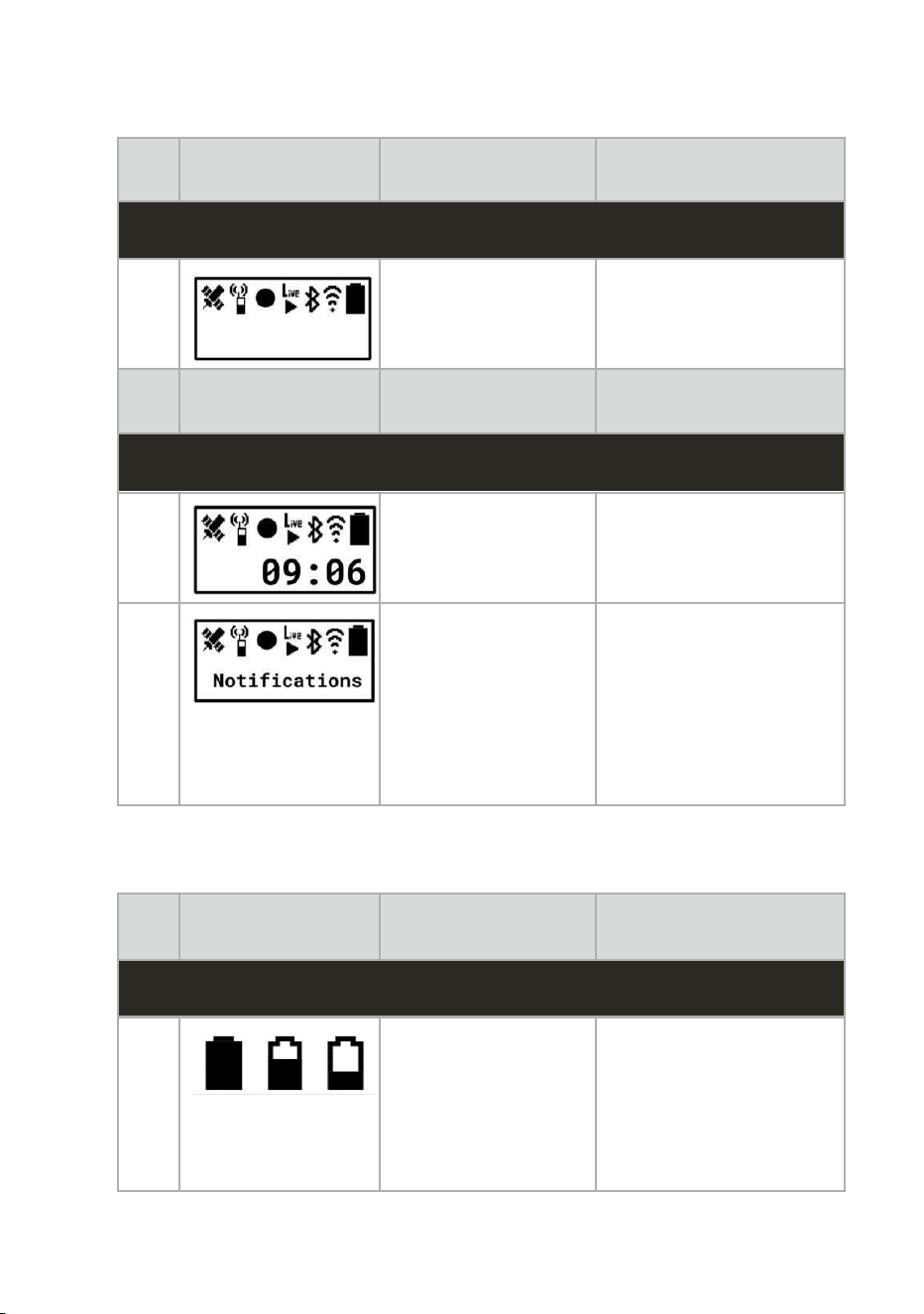
4.6. Icons and Notifications
The BWC displays various icons and notifications on the LCD
screen to provide users with real-time information about the device
status, operational modes, and alerts. These visual indicators help
users quickly understand the current state of the camera, such as
recording status, battery level, connectivity, storage availability, and
system notifications. The table below will describe the different icons
and when it's displayed on the LCD screen.
SL
NO
Icon / Message
Description
When Displayed
HOME SCREEN
1
Displays different
status icons on the
LCD screen.
Device Menu → Basic
Settings → Wi-Fi
SL
NO
Icon / Message
Description
When Displayed
HOME SCREEN
2
Displays the current
system
Device Menu → Basic
Settings →Bluetooth
3
Display notifications
on the LCD screen
Device Menu → Basic
Settings → Select BT
Device → Scanning....
→ After scanning
completes, highlight
the desired device
select and pair.
Table 6. LCD Home Screen
SL
NO
Icon / Message
Description
When Displayed
ICONS
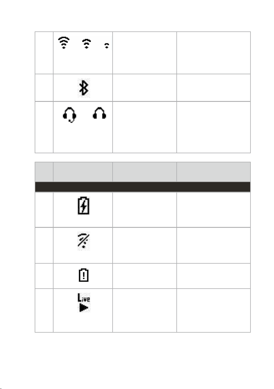
1
Indicate the battery
levels
As the battery is
drained during
operation, the level
shown in the battery
icon decreases
accordingly
2
Indicate Wi-Fi signal
strength
The number of bars
displayed in the icon
decreases as the Wi-Fi
signal strength
becomes weaker
3
Indicates the
Bluetooth status of
the device.
Displayed when
Bluetooth is enabled.
4
Indicates that a
wired headset (with
or without a
microphone) is
connected to the
device
Displayed when any
wired headset (with or
without a microphone)
is plugged into the
device
SL
NO
Icon / Message
Description
When Displayed
ICONS
5
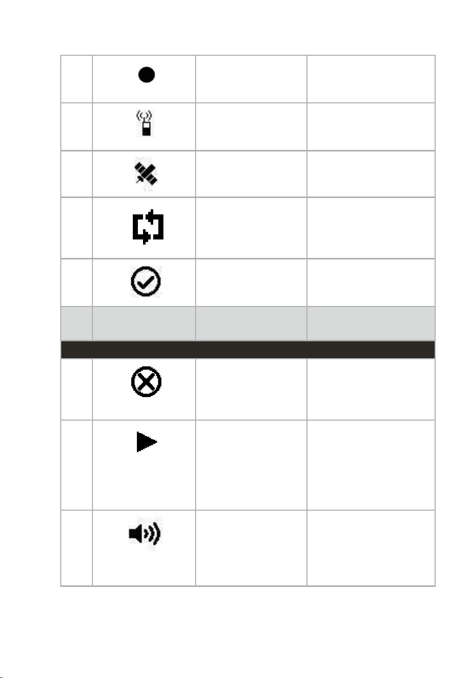
Indicates that the
device is connected
to a power source
and charging.
When the device is
connected to a charger
or docking station.
6
Indicates that the
device is not
receiving any Wi-Fi
signal.
When Wi-Fi is turned
on and no network is
connected or no Wi-Fi
signals are detected.
7
Indicates that the
battery charge is low
When the battery level
is between 1–20%.
8
Indicates that the
device is currently
streaming live video
to a connected
network or server
Displayed when live
streaming is active.
9
Indicates that video
recording is in
progress.
Displayed when the
camera is actively
recording video.
10
Indicates that the
Push-to-Talk func
tion is active
Displayed when PTT
function is activated.
11
Indicates GNSS
status and satellite
signal availability.
Displayed when GNSS
is enabled and satellite
signal is detected
12
Indicates that Pre
Recording feature is
enabled.
Displayed when the Pre
Recorder is turned ON
and the device is
capturing videos.
13
Indicates that an
incoming request
has been accepted
Displayed briefly when
the user accepts a
request or connection
SL
NO
Icon / Message
Description
When Displayed
ICONS
13
Indicates that an
incoming request
has been rejected or
denied
Displayed briefly when
the user rejects a
request or connection
14
Indicates the
currently highlighted
or selected item in
the settings menu.
Displayed next to the
menu item that is
currently highlighted
while navigating using
the Volume Up/Down
buttons
15
Indicates that an
incoming
Push-toTalk (PTT)
call is being
received
Displayed on the LCD
screen when the device
is receiving an
incoming PTT call.
16
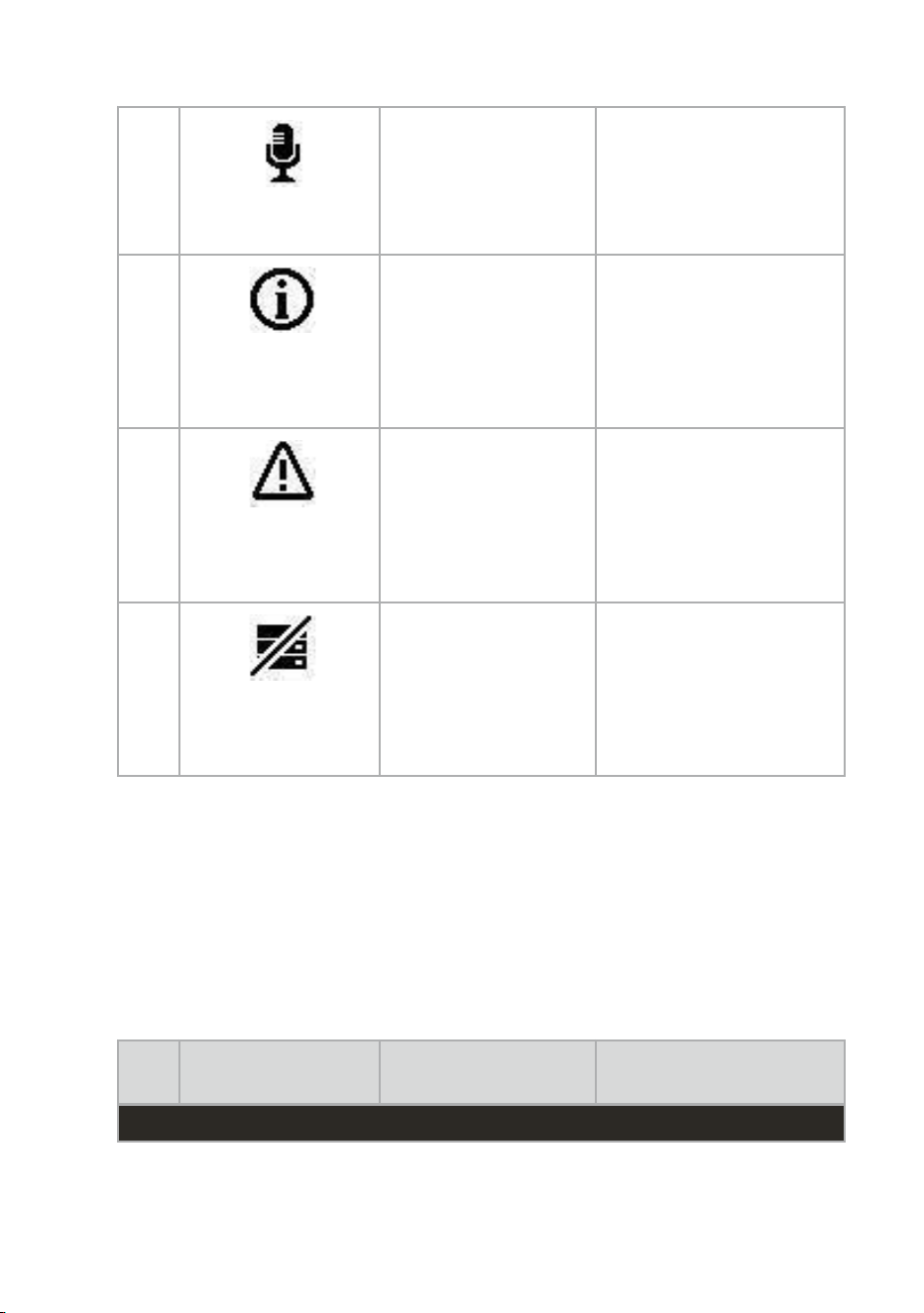
Indicates that the
device is actively
transmitting a
Push-to-Talk (PTT)
call
Displayed on the LCD
screen while the PTT
button is pressed and
the device is sending
audio.
17
Indicates that
additional
information, tips, or
system messages
are available for the
user.
Displayed when the
device needs to show
a notification, tip, or
informational message
on the LCD screen
18
Indicates that a
system error or
malfunction has
occurred and user
attention may be
required.
Displayed when device
detects a system,
hardware or operational
error
19
Indicates that the
device’s storage is
completely full and
cannot store any
additional files or
recording.
Displayed when the
device’s storage has
reached its maximum
capacity and no more
data can be saved.
Table 7. LCD Icons
SL
NO
Icon / Message
Description
When Displayed
NOTIFICATIONS
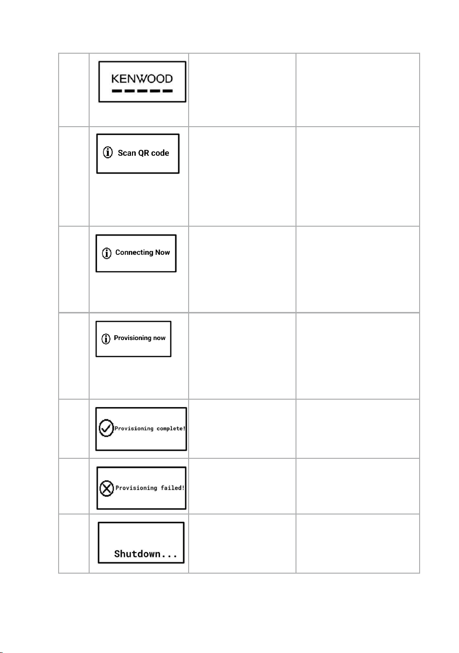
1
Indicates that the
device is initializing
and loading during
startup.
Displayed on the LCD
screen when the device
is powered on and is in
the process of starting
up.
2
Indicates that the
device is not
provisioned and
needs to connect to
a Wi-Fi in order to
proceed further for
provisioning.
Displayed on the LCD
screen when the device
is powered on for the
first time.
3
Indicates that the
device has
successfully read
the QR code and
now connecting to
the Wi-Fi network
Displayed on LCD when
the device is connecting
to Wi-Fi
4
Indicates that the
device has
successfully
connected to Wi-Fi
and the provisioning
process has begun.
Displayed on LCD when
the device is
provisioning.
5
Indicates that the
device provisioning
is completed.
Displayed on the LCD
screen when the device
provisioning is
completed.
6
Indicates that the
device provisioning
is failed.
Displayed on the LCD
screen when the device
provisioning fails.
7
Indicates that the
device is in the
process of shutting
down.
Displayed when the
device is powered off or
shutting down.
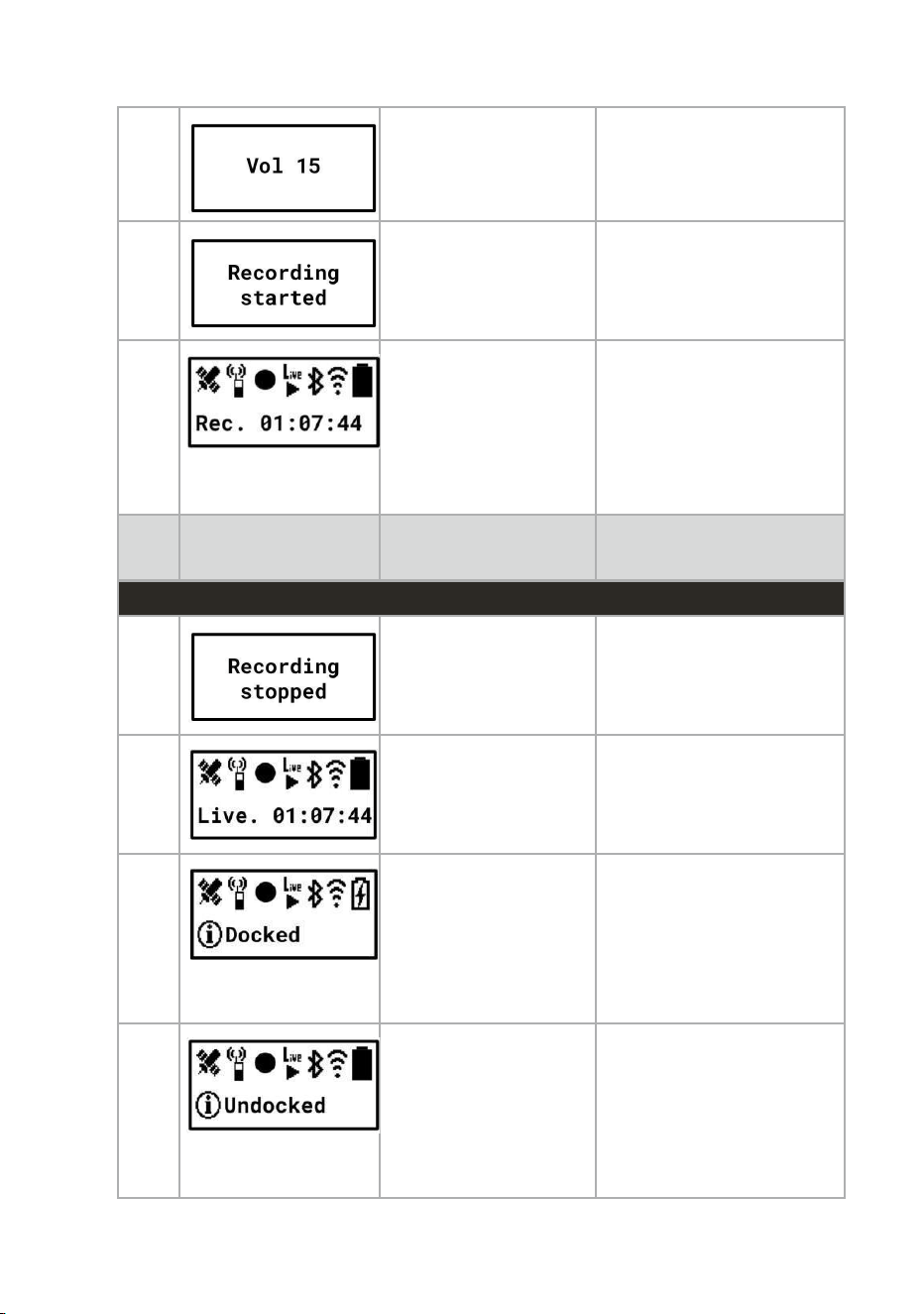
8
Displays the current
volume level of the
device.
When the Volume Up or
Volume Down button is
pressed.
9
Indicates that the
recording has
started successfully.
Displayed when the
user starts recording
video by pressing the
Record button.
10
Displays the
elapsed time of the
ongoing recording.
Displayed on the LCD
home screen while
recording is in
progress, showing the
duration of the
recording.
SL
NO
Icon / Message
Description
When Displayed
NOTIFICATIONS
11
Indicates that the
recording has been
stopped
successfully.
Displayed when the
user stops recording
video by long pressing
the Record button.
12
Displays the
elapsed time of the
ongoing live
streaming session.
Displayed on the LCD
home screen while live
streaming is active.
13
Indicates and
confirms the device
is properly docked
and charging
Displayed on the LCD
home screen when the
device is securely
connected to the
charging
dock
14
Indicates that the
camera has been
removed from the
charging dock and
is running on battery
power.
Displayed on the LCD
home screen when the
device is detached from
the charging dock.
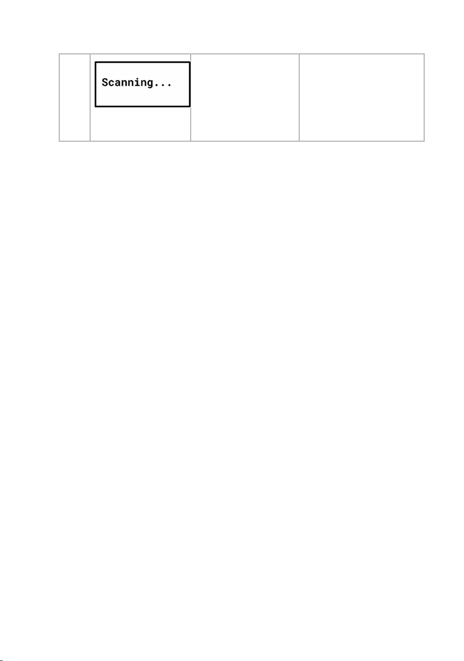
15
Indicates that the
camera is
searching for
nearby Bluetooth
devices for pairing
or setup.
Displayed on the LCD
screen when Bluetooth
scanning is initiated
from settings.
Table 8. LCD notifications
Disclaimer: Some notifications and settings messages may be too long to fit on the LCD
screen. In such cases, the text will automatically scroll to the left after 2 seconds so that the
full message can be read.
4.6.1 Navigating between notifications in LCD UI
When multiple notifications are available, they can be viewed one at a
time on the LCD.
● The most recent notification is displayed first.
● Press the Power button to view the next (older) notification, if available.
● Continue pressing the Power button to cycle through all available
notifications.
● After the last notification is displayed, pressing the Power button again
returns the LCD to the normal time display.
● While navigating through notifications, the status icons at the top of
the LCD remain unchanged. Only the notification area at the bottom
of the screen, including the notification message and timestamp, is
updated.
Note: Notifications are displayed in reverse chronological order
(newest first).
Example:
Assume the following sequence of events:
1. The device detects Wi-Fi Signal is Poor.
2. Later, the device detects that the battery is Low.
In this case:
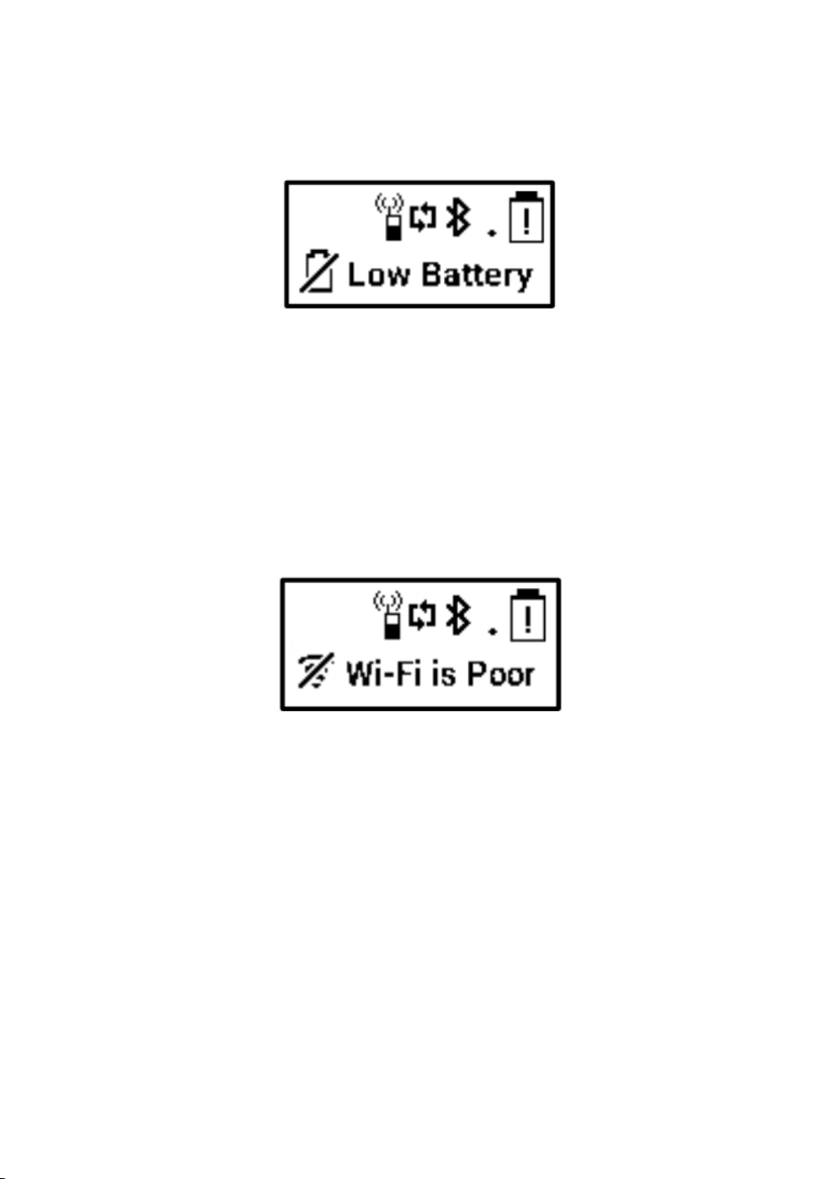
1. The LCD initially displays the Battery is Low notification (the most
recent notification).
Figure 1 4. LCD notification -Low Battery
2. Press the Power button once to display the earlier Wi-Fi Signal is
Poor notification.
Figure 15. LCD notification - Wi-Fi is poor
3. Press the Power button again to return to the normal time display
(provided there are no additional notifications).
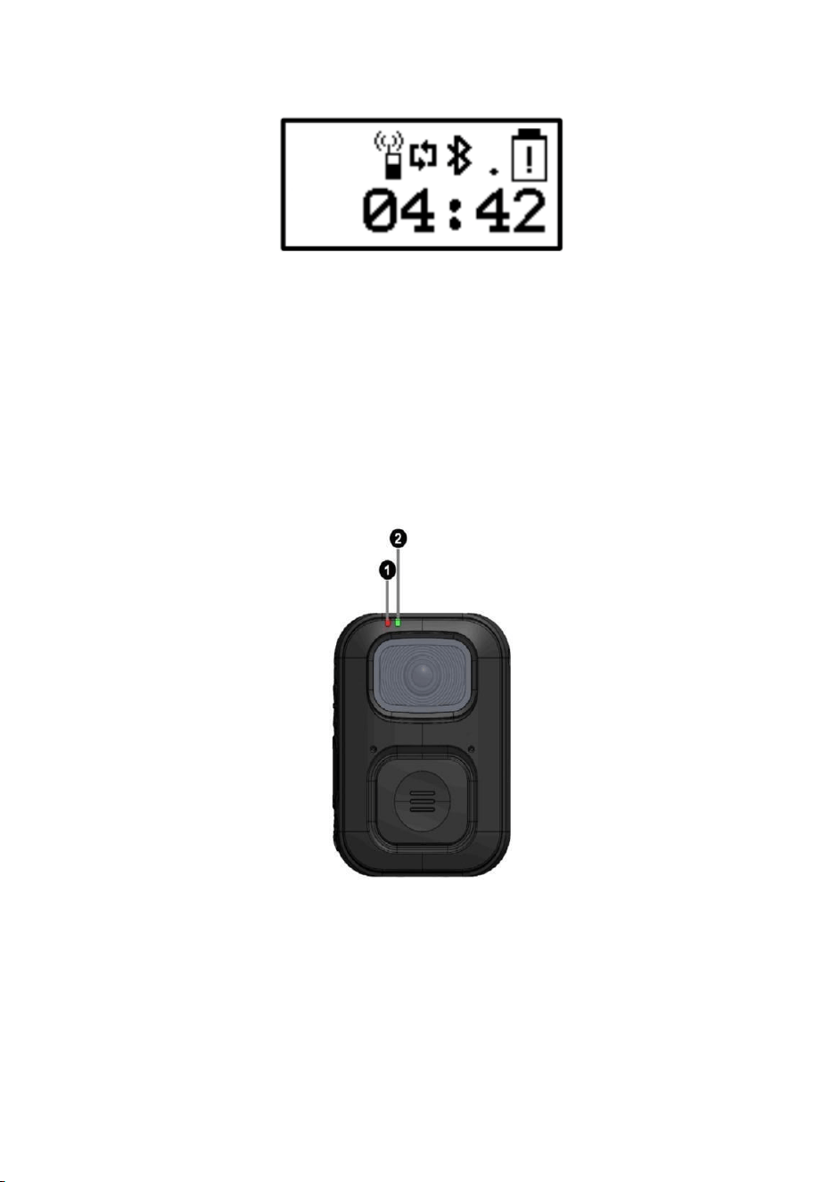
Figure 16. LCD home screen
This navigation method allows users to review all active notifications in the
order they occurred, starting with the most recent, before returning to the
normal LCD display.
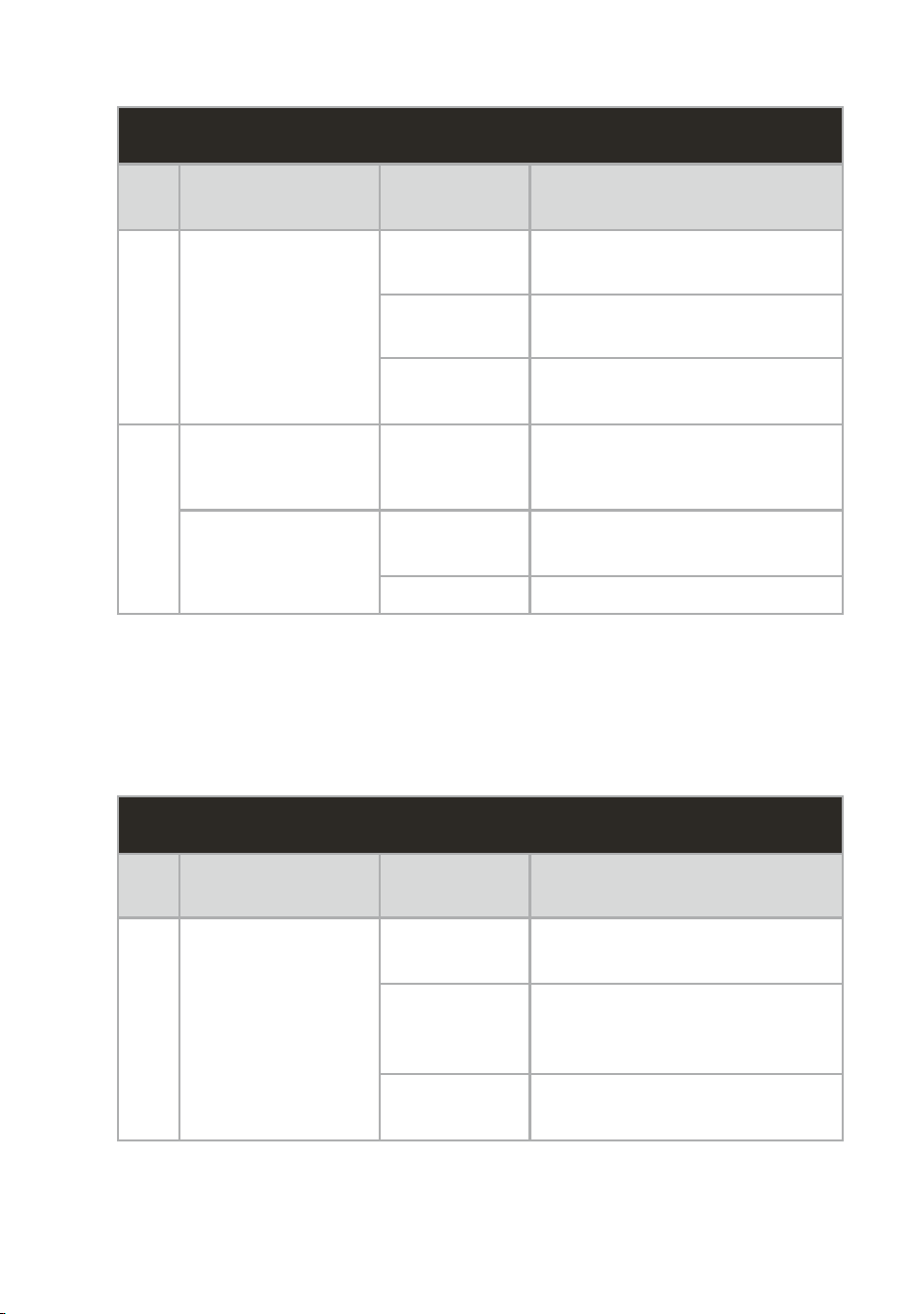
4.7. LED Indicator
Figure 17. Front View of the Device Showing Both LEDs
The device uses two LED indicators one red and one bi-colour to display
its current operating status, battery condition, and system activity. Please
refer to the table below for detailed information.
DURING OPERATION
SL
NO
LED
COLOUR
MODE
FUNCTION
1
● RED
Solid
Recording / Streaming in
progress
Blinking
Device memory low or
streaming error
Off
Device powered off or backup
recording in progress
2
● GREEN
Solid
Normal operation with battery
level above 50%
● ORANGE
Solid
Battery level between 10%
and 50%
Blinking
Battery low (Below 10%)
Table 9. LED indication during operation
The device uses two LED indicators one red and one bi-colour to display
its current operating status, battery condition, and system activity. Please
refer to the table below for detailed information.
WHEN DEVICE IS CONNECTED TO DOCK
SL
NO
LED
COLOUR
MODE
FUNCTION
1
● RED
Solid
Waiting for processing to
initiate (standby state)
Blinking
System update or video
upload in progress (e.g., OS
update)
Off
System load and video upload
completed
2
● GREEN
Solid
Battery fully charged
Blinking
Charging in progress
● ORANGE
Blinking
System error detected
Off
Charging not Started
Table 10. LED Indication when dock
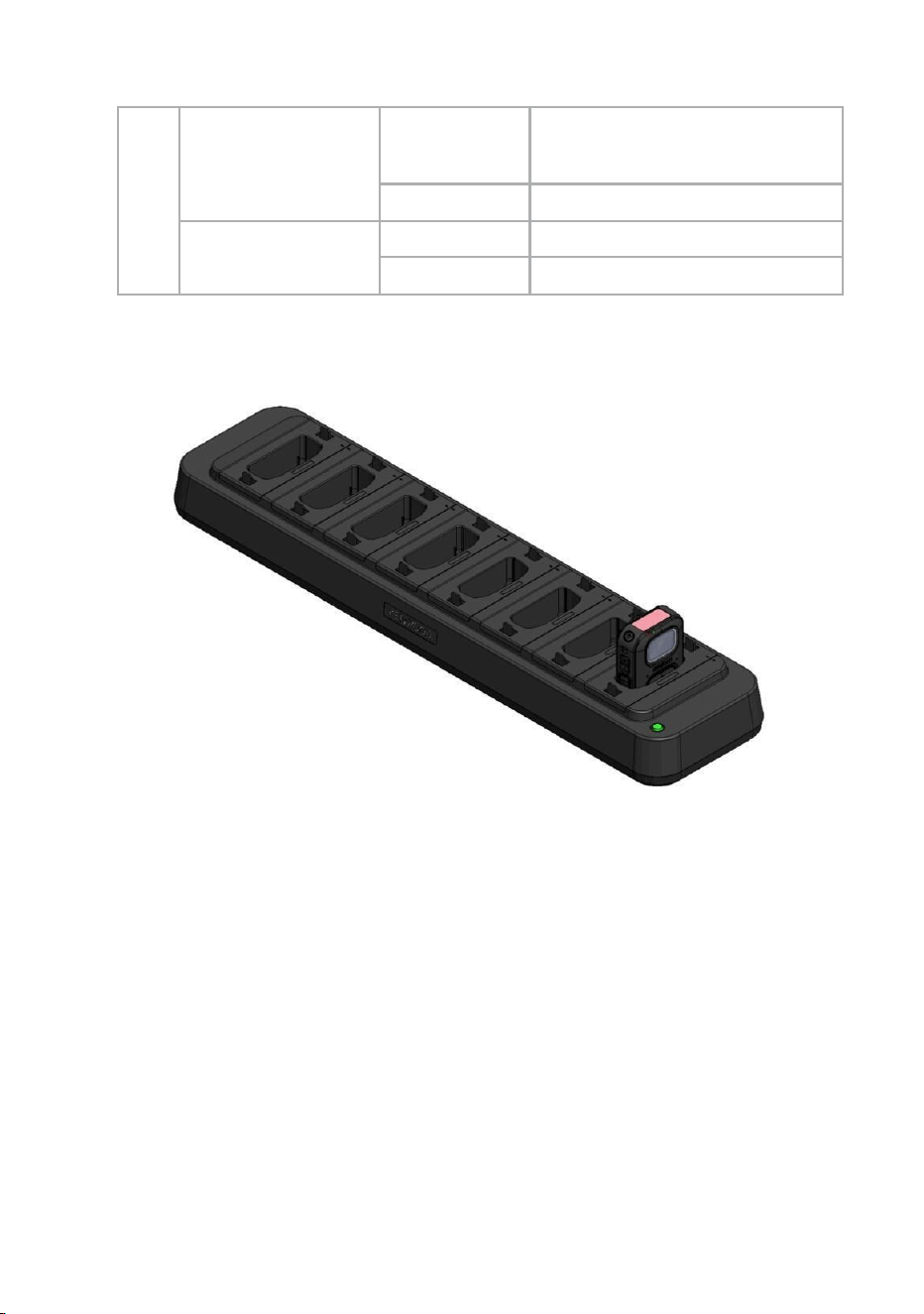
Figure 18. Device connected to dock
4.8. Sound Indicators
The device provides audible cues to indicate its current status and user
actions. These sound indications help the user quickly understand the
device’s operation without needing to look at the display or LEDs. The
following table summarizes the different sounds and their meanings.
SL
NO
Event / Operation
Sound
Indication
Description
1
Successful Bootup
Bootup Tune
A bootup tune is played to
indicate that the device has
powered on successfully.
2
Button Press
Single Beep
A single beep sound is heard
whenever any button on the
device is pressed.
3
Record Button
Pressed
(Start Recording)
Beep + Start
Tune
A short beep followed by a
recording start tone is played
when the record button is
pressed to begin recording.
4
Record Button
Long Pressed
(Stop Recording)
Beep + Stop
Tune
A short beep followed by a
recording stop tone is played
when the record button is
long-pressed (3 seconds) to
stop recording.
5
Record Button
Pressed
(Storage Full)
Beep + Error
Tone
A short beep followed by an
error tone is played if the
record button is pressed when
the device storage is full.
Table 11. Sound Indications During Operation
4.9. Charging Instructions
Proper charging ensures that the device operates reliably and maintains
battery health. The device can be charged using either the JVC Kenwood
Docking Station or a standard 5V USB Type-C charger.
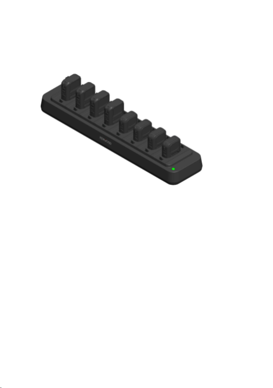
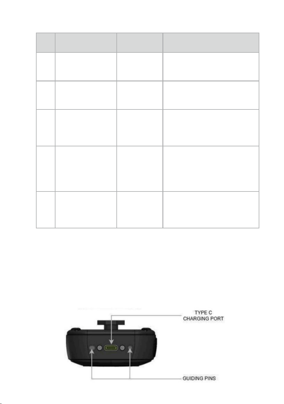
Figure 19. Bottom view of device
4.9.1 Charging Using JVC Kenwood Docking Station
Figure 20. Multiple Body-Worn Cameras Connected to Docking Station
4.9.2 Charging Using Standard 5V USB Type-C Charger
The body-worn camera can be charged directly using a standard 5V
USB Type-C charger. This method is suitable when a docking station is
not available and allows convenient charging from a wall outlet or
compatible power source.
• Connect a 5 V USB Type-C charger to the USB Type-C port on
the body-worn camera.
• Plug the charger into a standard AC power outlet.
• The Green charging indicator LED on the device will begin
blinking, indicating that charging is in progress.
• Once the battery is fully charged, the Green LED will turn solid.
• After charging is complete, unplug the charger from the power
outlet and disconnect the USB Type-C cable from the camera.

4.9.3 DOCK station
The Docking Station is used to charge the Body Worn Camera (BWC)
and upload recorded files to the server simultaneously. This enables
the device to recharge while securely transferring recordings and other
data.
The Docking Station supports simultaneous charging and data transfer for
up to eight connected BWCs, allowing efficient charging and automatic
upload of recordings in parallel.
Dock Interfaces
The Docking Station includes the following ports:
● 8 USB Type-C Bays – The Docking Station provides eight USB
Type-C ports for connecting Body Worn Cameras (BWCs). A single
BWC or up to eight BWCs simultaneously can be connected for
battery charging and secure data transfer to the server.
● DC Power Jack – Connect the supplied power adapter to provide
power to the Docking Station.
● RJ45 Ethernet Port – Connect an Ethernet cable to provide network
connectivity. This enables the Docking Station to upload recordings
and other device data to the server.
● DIP Switch – Used to switch between Fast charging and normal
charging.
Protection Features
The Docking Station includes built-in protection mechanisms to prevent
charging or data transfer when abnormal conditions are detected.
1. Moisture Detection
2. Temperature Protection

If moisture is detected in the BWC's USB Type-C connector or if the
temperature of the BWC's USB Type-C connector exceeds the safe operating
limit, the Docking Station prevents:
● Battery charging
● Data transfer
Fault Indication:
For both Moisture Detection and Temperature Protection, the
Docking Station indicates the fault by blinking the Yellow LED until the
condition is cleared.
4.9.4 Charging Precautions using DOCK
To ensure safe operation, optimal charging performance, and long
battery life, observe the following precautions when charging the device:
• Use only the supplied docking station or a certified 5V USB
Type-C charger to charge the device.
• Ensure that all charging connectors are clean and free from
dust or moisture before connecting the device.
• Do not charge the device in extremely hot or cold
environments. Recommended charging temperature ranges are:
→ Fast Charging Mode (3A / 5V) :5°C to 25°C
→ Normal Charging Mode (1.5A / 5V) : 25°C to 40°C
• Charging outside the specified temperature range may reduce
battery life or affect charging efficiency.
• Avoid placing the docking station or charger in direct sunlight or
near heat sources.
• During charging, the device may become slightly warm, this is
normal and does not indicate a malfunction.
When using the docking station, the Type-C USB 3.1 port and guiding pins
on the device ensure correct alignment and secure connection for both

charging and data transfer. The following steps describe the correct
procedure to charge the device safely and efficiently.
• Place the docking station on a flat, stable surface. Make sure that
there is enough area around the docking station for the easy
insertion and removal of the devices.
• Connect the docking station to a power source using the supplied
DC adapter.
• The docking station supports two charging modes: Normal
Charging Mode (1.5 A / 5 V) and Fast Charging Mode (3 A / 5
V). Select the desired mode using the DIP switch located on the
bottom of the docking station.
• Insert the body-worn camera into the docking slot, ensuring that
the Type-C charging port and guiding pins on the device are
properly aligned with the corresponding contacts on the docking
station.
• Make sure the device is securely and fully docked to enable
proper charging and data transfer.
• The charging indicator LED (Green) on the device will start
blinking, indicating that charging has begun.
• When charging is complete, the Green LED will turn solid.
• Once charging is complete, carefully remove the device from the
docking station.
D
OCK LED INDICATOR
SL
NO
LED
COLOUR
MODE
FUNCTION
1
● BLUE
Solid
Normal charging
2
● GREEN
Solid
Fast charging
3
● YELLOW
Solid
Moisture fault
Table 12. Docking Station LED Status IndicationsStation
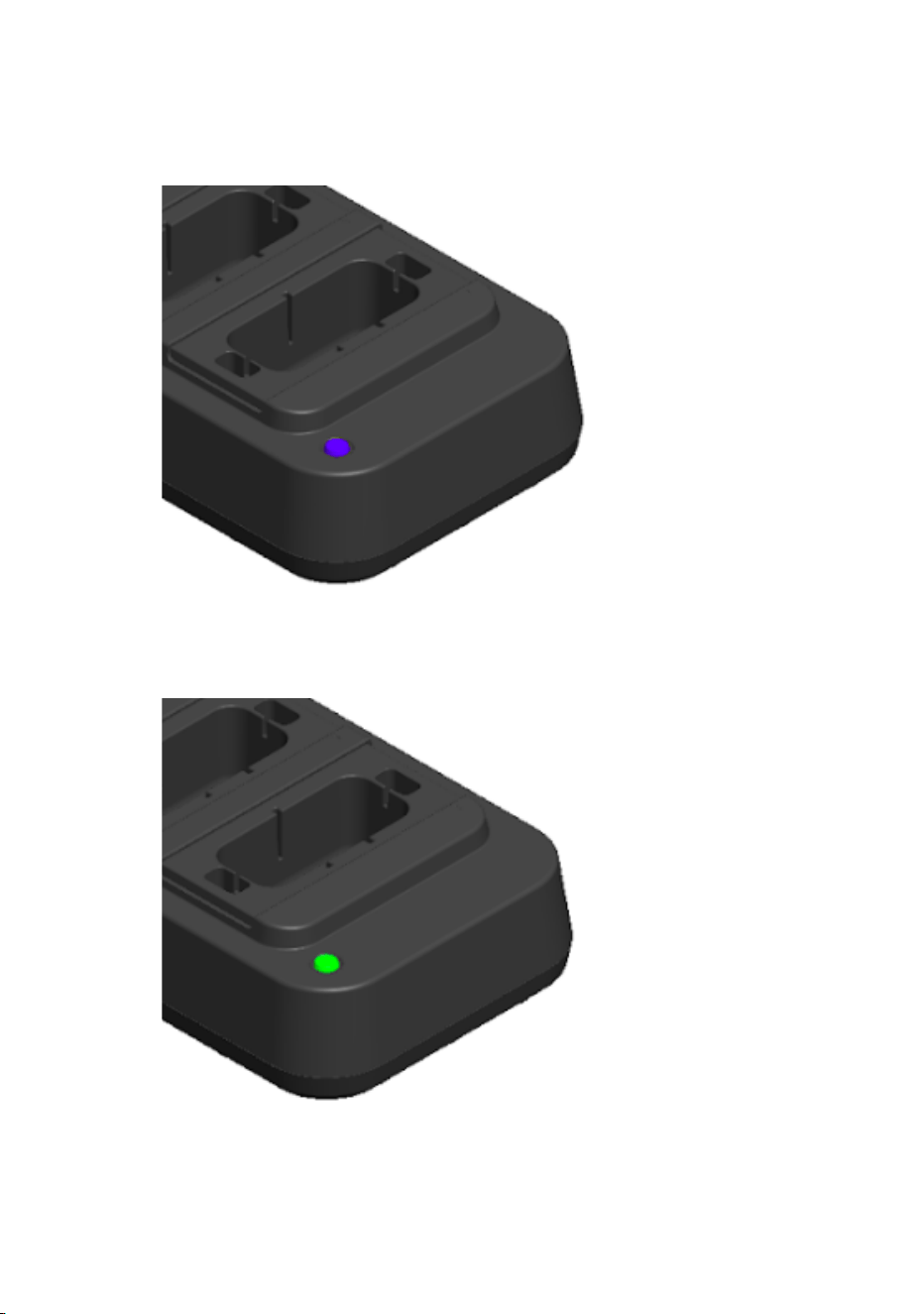
Figure 21. DOCK Blue LED indicates normal charging
Figure 22. DOCK Green LED indicates Fast charging
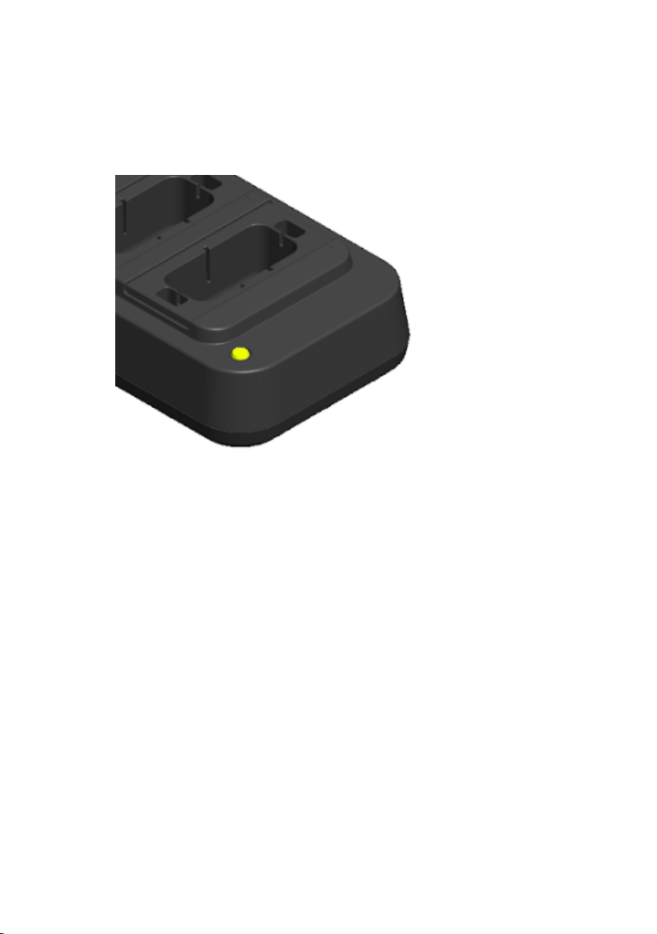
Figure 23. DOCK Yellow LED for moisture or temperature fault
• Disconnect the charger or remove the device from the docking
station once charging is complete to prevent unnecessary power
consumption.
• Use only original accessories provided or approved by JVC
Kenwood for optimal performance and safety.
• Charge the device only in dry, well-ventilated indoor environments.
• Do not use the device if the charging cable or connector is
damaged. Replace damaged accessories immediately.
• Do not cover the device or docking station during charging, as this
may cause overheating.
• Do not attempt to disassemble, modify, or repair the battery or
charging components.
4.10. How to Attach the Camera
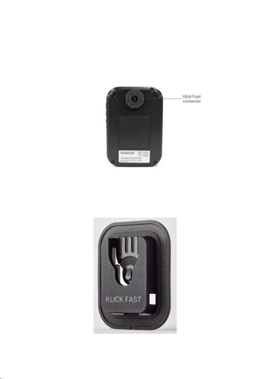
The camera can be mounted to the body using the Peter Jones Klick Fast
connector in device and the Klick Fast shoulder/chest strap.
• Ensure the Klick Fast connector is available on the rear side of the
camera.
Figure 24. Click Fast connector behind the device
• Locate the strap connector on the Klick Fast shoulder/chest strap.
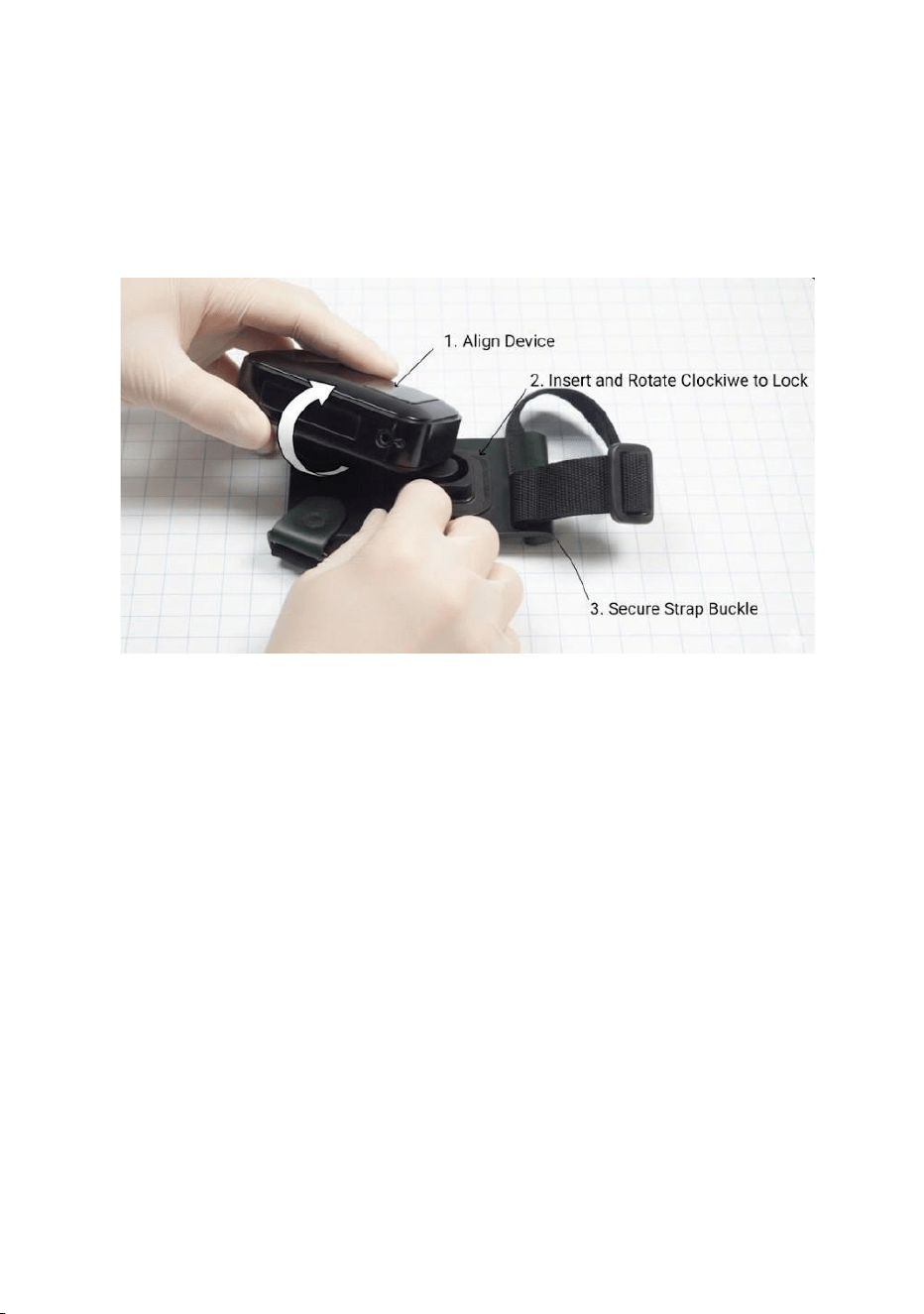
Figure 25. Klick Fast shoulder/chest strap connector
• Hold the camera upside down and insert the camera connector
into the strap connector until it gets locked.
Figure 26. Connection between strap and connector
• Once locked, rotate the camera into the correct upright position.
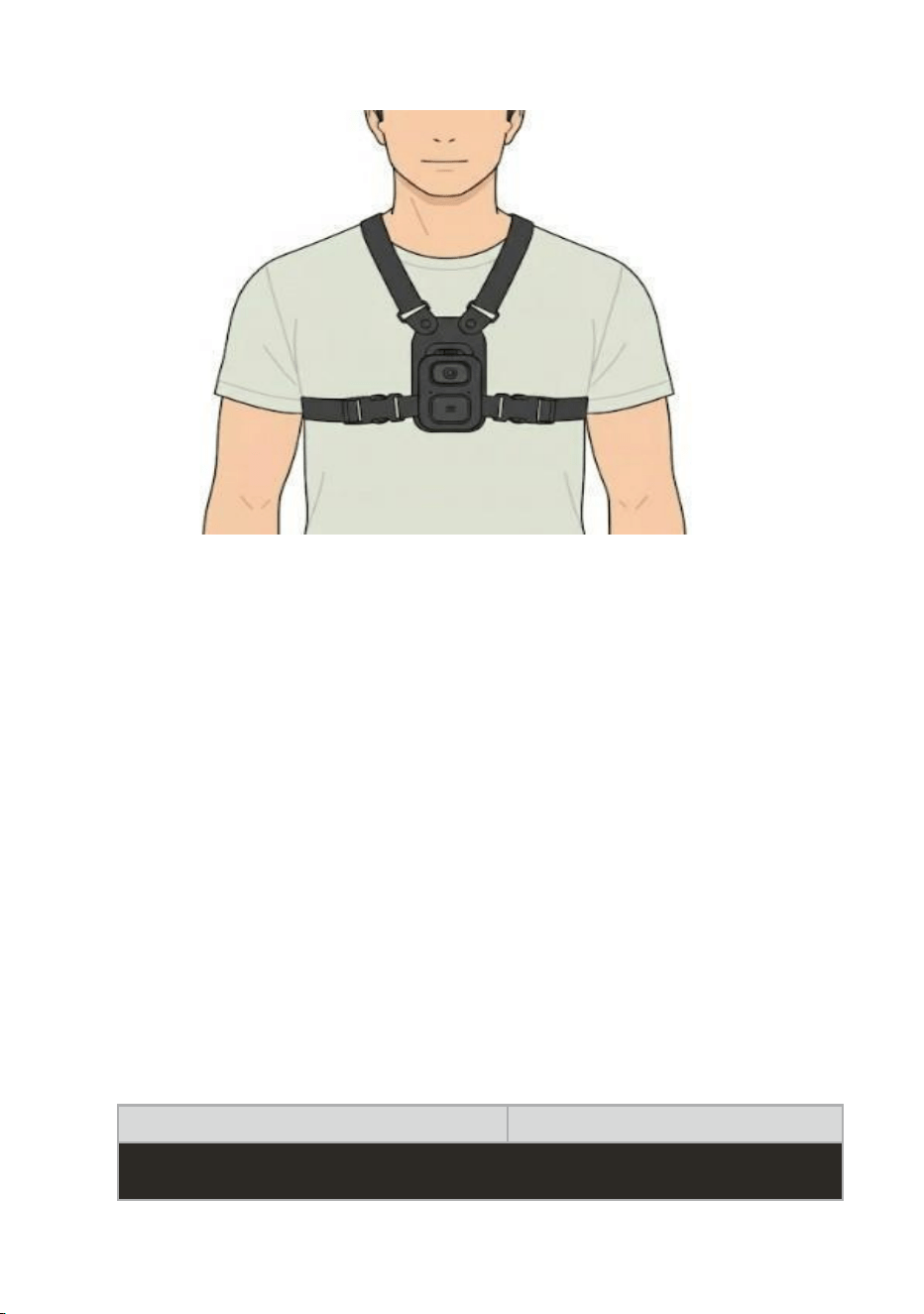
Figure 27. Final overview
4.11. Accessing Web UI
The device features a built-in Web User Interface (Web UI) that allows
you to manage and configure the device remotely using any standard
web browser. However, the Web UI can only be accessed if your device
and the computer (or mobile device) you're using are connected to the
same Wi-Fi network.
• Device IP address can be fetched from the LCD menu. Refer to
the below table on how to fetch WiFi IP address:
Icon / Message
When Displayed
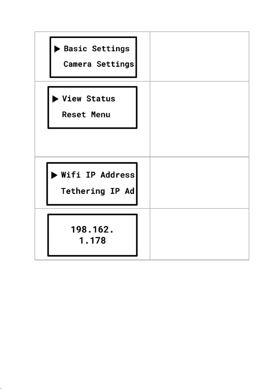
Press the menu button
Navigate to “View Status” option
Press Volume Up (+) : Navigate
Up
Press Volume Down (-) :
Navigate
Down
Press “Menu” button to select the
“View Status” option
Navigate to “Tethering IP” option
Press “Menu” button to select
IP address will be displayed on
the screen
Table 13. Steps to find Device IP Address
The Body Worn Camera (BWC) provides a secure HTTPS-based Web User
Interface (Web UI) for device configuration and monitoring.
To access the Web UI:
1. Ensure the BWC and the computer are connected to the same
network.
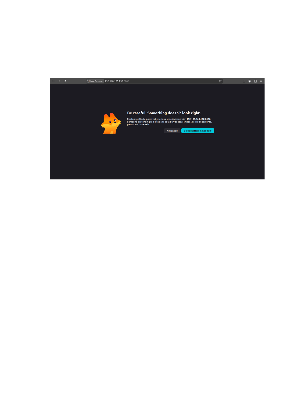
2. Open a supported web browser (Images shown here are Mozilla
Firefox).
3. In the address bar, enter the following URL:
https://<BWC_IP_Address>:8080
Figure 28. Web UI - not secure
4. The browser may display a security warning. The appearance of this
warning may vary depending on the browser.
5. In Mozilla Firefox:
○ Click Advanced.
○ Scroll down
○ Click Proceed to <IP Address> (Accept the Risk and
Continue).
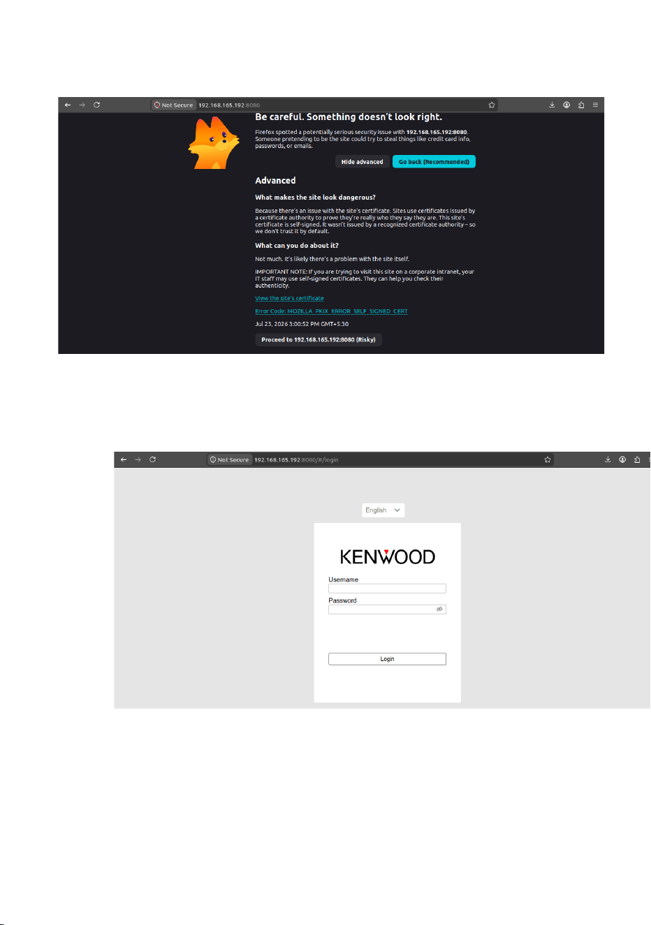
Figure 29. Web UI - proceed to Web UI
6. The Web UI Login page will be displayed.
Figure 30. Web UI - Login page
7. Enter your login credentials and click Login.
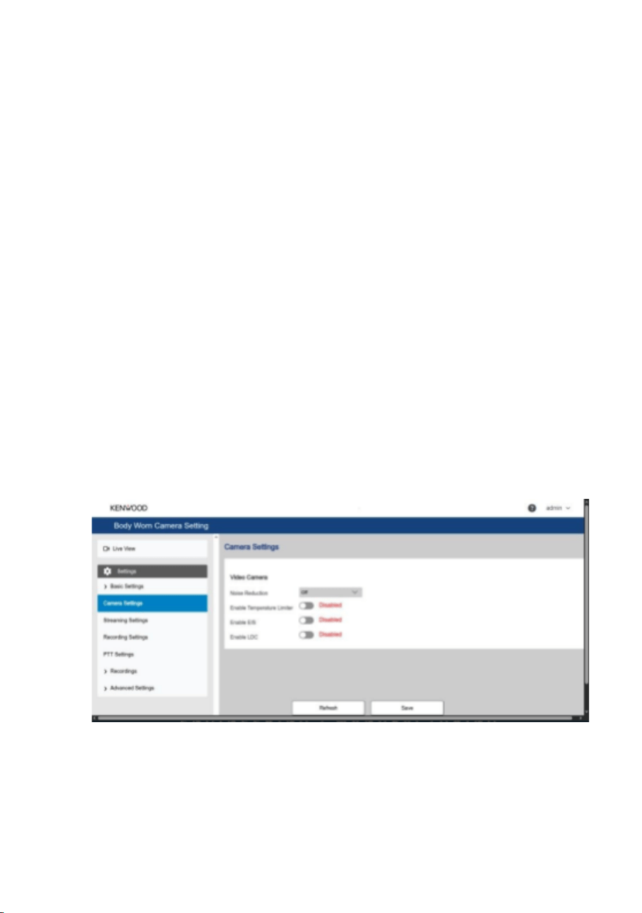
Default credentials:
Username: admin
Password: admin
Note:
● The BWC uses HTTPS to provide a secure connection
between the device and the browser.
● If the BWC's IP address changes, the browser may
display the security warning again. In this case, repeat
the above verification steps to access the Web UI.
● The appearance of the security warning may differ slightly
across web browsers.
4.11.1 Web UI Guide
Once logged in, the Web UI will open, and you'll see a help menu in the
top right corner. The help menu is represented by a “?” icon, located to
the left of the User Account Menu.
Figure 31. Web UI Camera settings page
To Log out from Web UI:
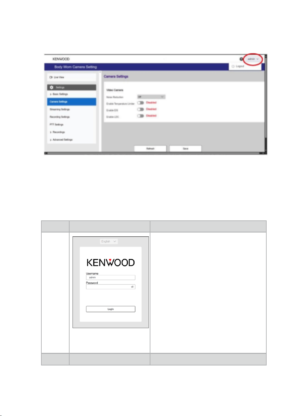
Click on - User Account Menu (top right corner) - then Logout
Figure 32. Web UI logout option
4.11.2 Connect Device to new WIFI
SL NO
Icon / Message
When Displayed
1
1. Open web browser and type
the following URL http://<IP
ADDRESS>:8080
Example :
http://192.168.68.144:8080
2. A log-in page will appear
3. Input user credentials
Username : admin
Password : admin
SL NO
Icon / Message
When Displayed
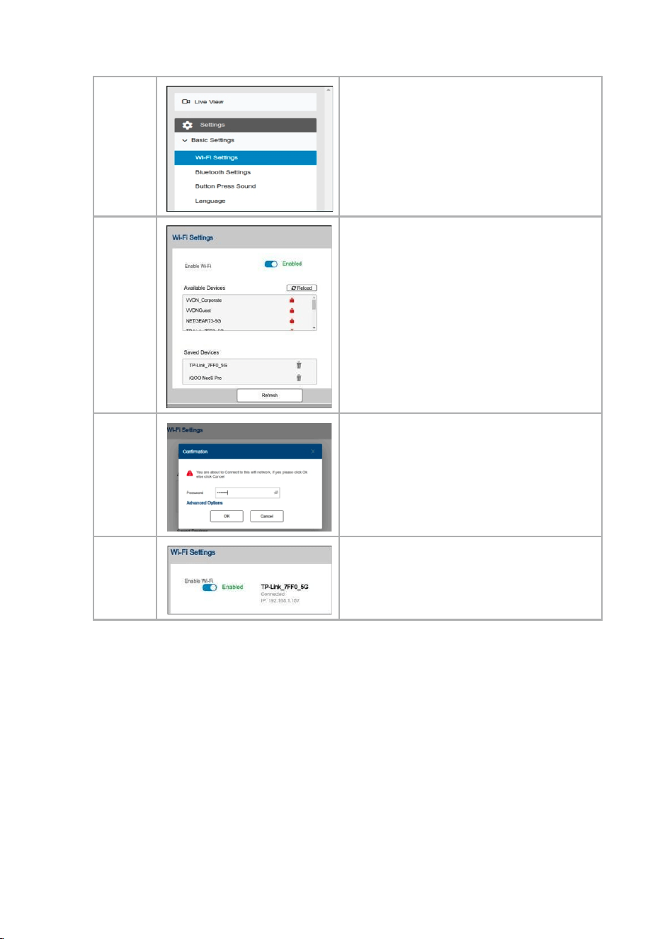
2
4. On the side panel menu, locate
“Basic Settings” and click on the
sub-menu “WiFi Settings”
3
5. Enable WiFi if disabled
4
6. Select a WiFi from the “Available
Devices” list and input password
Example : “FibeTV”
5
7. Once the connection is success,
you will see the WiFi listed near
Enable Wi-Fi icon
Table 14. Steps to connect device to WiFi
4.11.3 How to Start Recording
To start recording, press the Record button on the device.
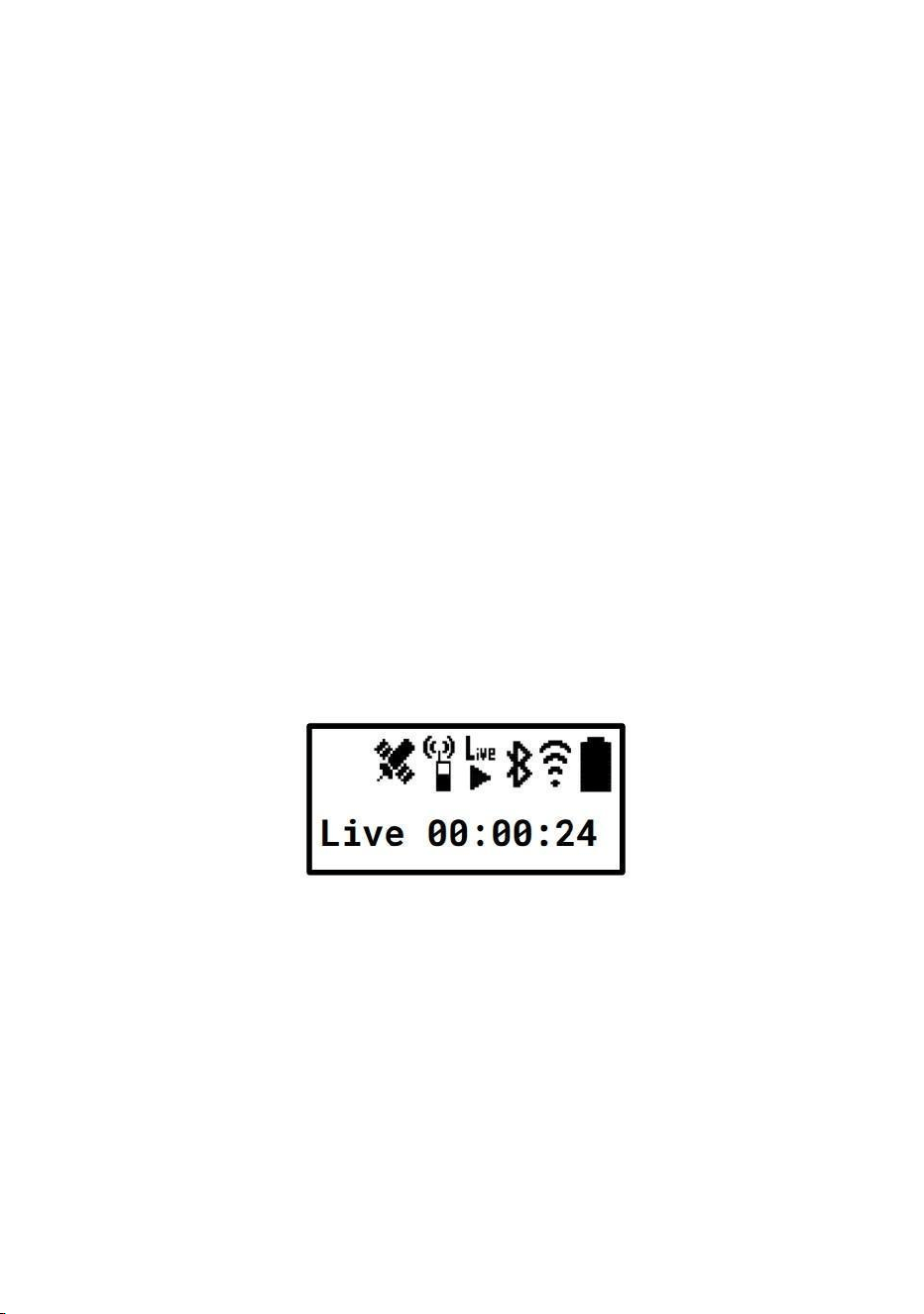
Once pressed, recording begins and the LCD interface displays the
recording icon along with the recording timer, as described in the Icons
and Notifications section.
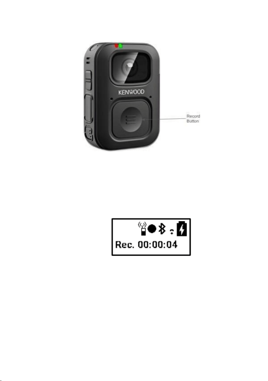
Figure 34. Front view of device
To stop recording, press and hold the Record button for 3 seconds. The
recording will stop, and the recording icon and timer will disappear from
the LCD screen.
Figure 35. Recording Icon and timer
Default recording setting:
Recorder default resolution : 1080p
Recorder bitrate : 5000kbps
Increase the maximum bitrate to : 20000kbps
Recorder default FPS: 30fps
Note: These settings can be changed from Web UI or Engineering tool.
4.11.4 How to Start Live streaming
To initiate live streaming, connect the device to a Wi-Fi network, ensure
that both the device and the PC are connected to the same network,
obtain the device IP address, and access the stream using a
RTSP-compatible media player with the URL
rtsp://<device_ip>:8554/bwc_live1080p, You can view the live stream
using standard media streaming applications such as:
• VLC Media Player
• FFplay
• Any other RTSP-compatible media player
The device also provides a Live Streaming option within the Web User
Interface (Web UI). You may access the live video directly through the
Web UI without using an external media player.
Once the Live streaming is started the Live streaming Icon as well as
the Live streaming timer will be started automatically in the LCD UI as
described in the Icons and Notifications section.
Figure 36. Live streaming Icon and Timer
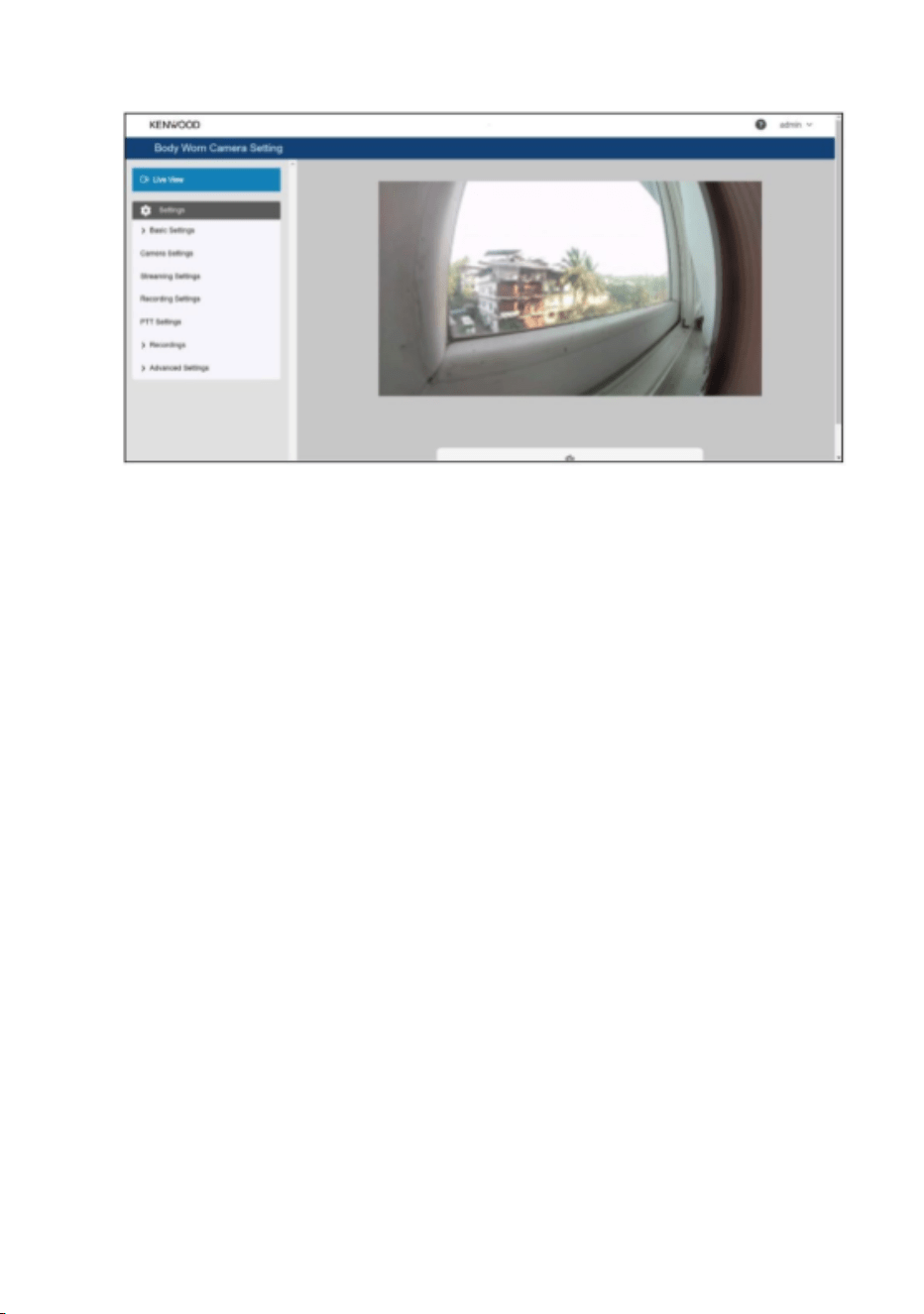
Figure 37. Web UI Live view tab
Default Streaming setting:
Streamer default resolution : 720p
Streamer bitrate : 500kbps
Increase the maximum bitrate to : 20000kbps
Streamer default FPS: 30fps
Note: These settings can be changed from Web UI or Engineering tool.
4.11.5 Overwrite Feature
The device includes an Overwrite feature to ensure continuous
recording when storage reaches full capacity.
The Overwrite feature can be enabled or disabled from either of the
following:
Using LCD UI: Refer to the LCD Settings Menu Table. 3 sections of this
document.
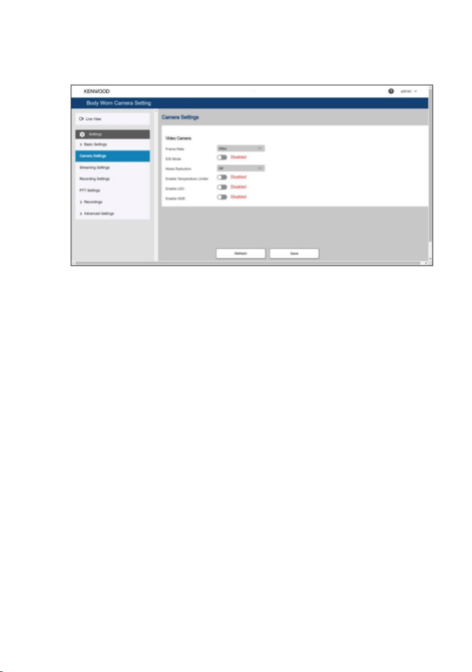
Using Web UI: Navigate to : Recording Settings → Enable Over write.
Figure 38. Web UI recording settings
When the Overwrite feature is enabled, the device will automatically
delete the oldest recorded video files to free up storage space and
save newly recorded videos without interruption.
4.11.5 Pre Recording Feature
The Pre Recording feature enables the Body Worn Camera (BWC) to
capture video 30 seconds or 60 seconds before the Record button is
pressed. This feature is useful when an incident occurs unexpectedly
and the user starts recording after the event has already begun,
ensuring that the moments leading up to the recording are also
captured.
The Pre Recording feature can be enabled or disabled through both the
Web UI and the LCD UI under Recording Settings.
● Web UI: Select the pre recording duration as 30 seconds or 60
seconds.
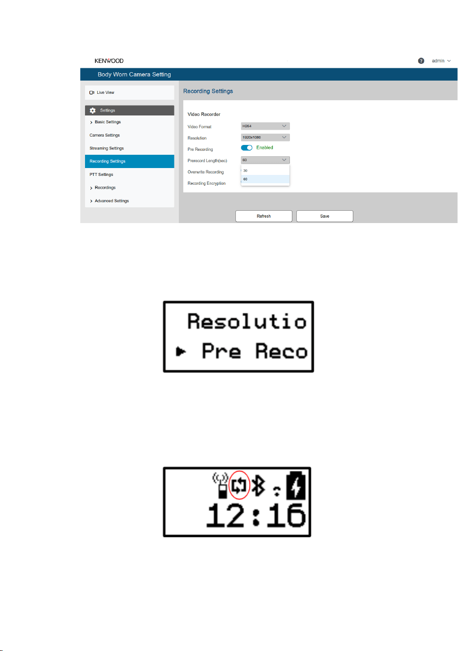
Figure 39. Web UI pre recording settings
● LCD UI: Enable or disable the Pre Recording feature.
Figure 40. LCD UI Pre recording settings
When the feature is enabled, a Pre Recording icon is displayed on the
LCD screen to indicate that the device is continuously buffering video for
pre recording.
Figure 41. Pre recoding icon on LCD UI
4.11.6 Using Push To Talk (PTT)
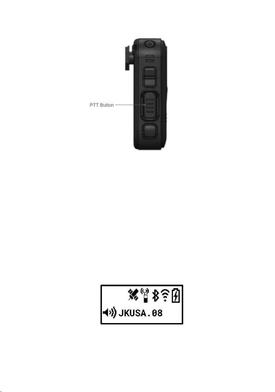
Figure 42. PTT Button
The Body Worn Camera supports Push-to-Talk (PTT) communication for
one-way voice transmission at a time.
• To speak, press and hold the PTT button, then start talking.
• Release the PTT button once you finish speaking.
• Only one device can transmit audio at a time.
→ The other user can speak only after the current speaker releases
the PTT button and then presses the PTT button on their device.
• During an active PTT call, the LCD screen on other devices displays
the Device ID of the device that is currently transmitting audio.
Figure 43. PTT Call

Listening to PTT Audio
• When another device is transmitting:
→ The receiving device automatically plays incoming audio
• Ensure:
→ Volume is turned up using Volume buttons
→ Speaker or headset is connected
• Visual indication:
→ PTT receiving icon appears on LCD
• User action:
→ No button press required to listen
→ Wait until current speaker releases PTT
PTT Setting in Web UI
● Navigate to PTT settings in Web UI to view PTT details such as:
App ID
App Name
App Version
Enable / Disable PTT APP
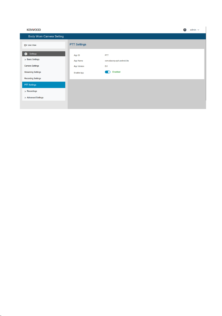
Figure 44. PTT Settings
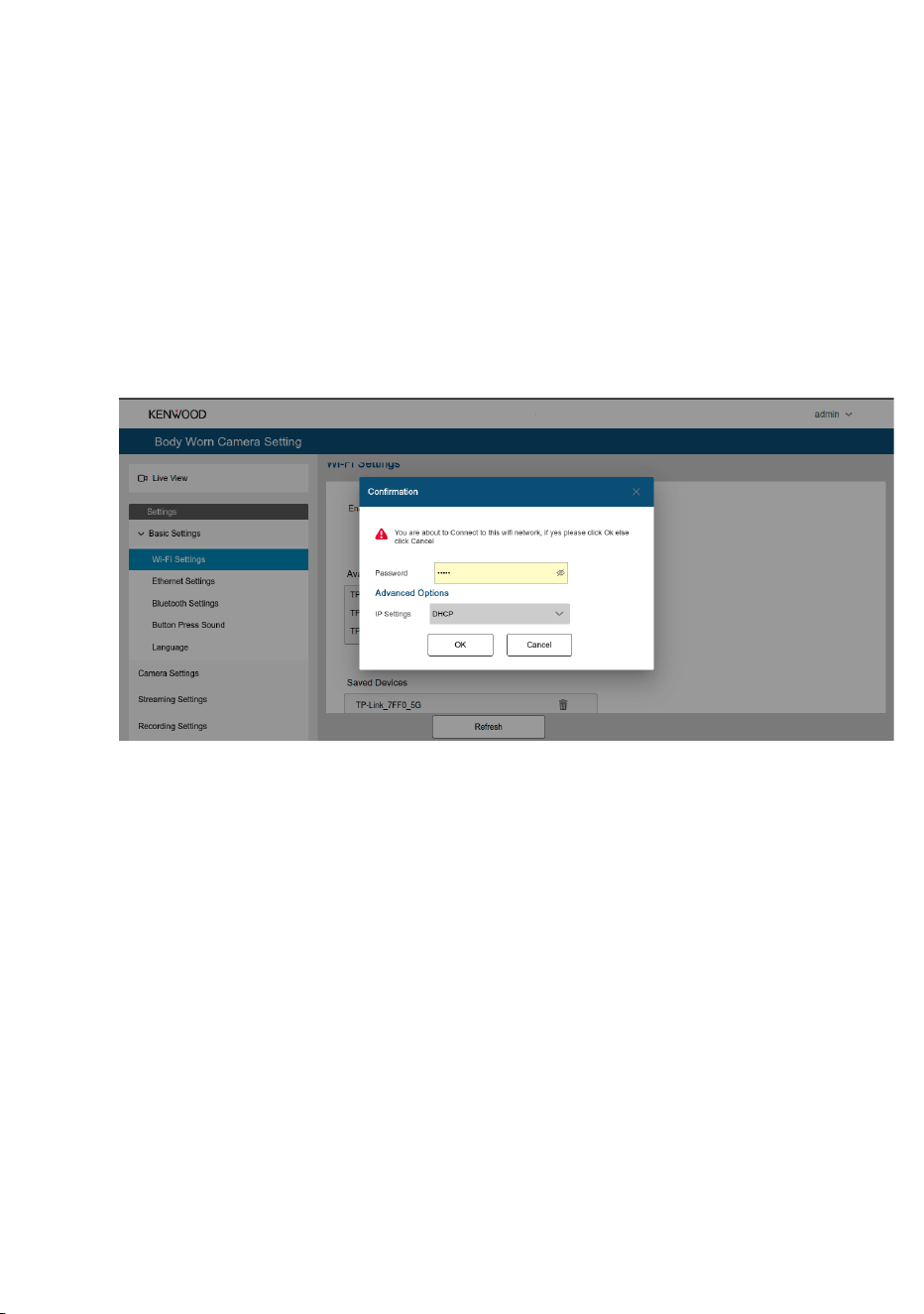
4.12. Wi-Fi Settings
The Wi-Fi Settings page allows you to enable or disable Wi-Fi, connect the
Body Worn Camera (BWC) to a wireless network, and configure network
settings.
To access the Wi-Fi settings:
1. Log in to the Web UI.
2. Navigate to Basic Settings > Wi-Fi Settings.
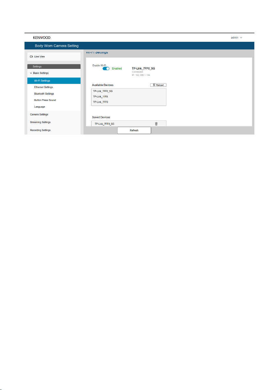
Figure 45. Web UI - Wi-Fi settings
The following options are available:
Enable Wi-Fi
Use the Enable Wi-Fi toggle switch to turn the Wi-Fi functionality ON or OFF.
When Wi-Fi is enabled, the currently connected network (SSID) and the
assigned IP address are displayed.
Available Devices
The Available Devices section lists all nearby Wi-Fi networks detected by the
BWC.
● Click Reload to refresh the list of available Wi-Fi networks.
● Select the desired network (SSID) to connect.
Saved Devices
The Saved Devices section displays Wi-Fi networks that have been previously
configured on the BWC.
● Selecting a saved network reconnects the device using the stored
credentials.
● Click the Delete icon to remove a saved network from the device.
Connecting to a Wi-Fi Network
1. Select the required Wi-Fi network from the Available Devices list.
2. Enter the Wi-Fi Password.
3. Click OK to connect, or Cancel to exit without saving.
Figure 46. Web UI - Advances Wi-Fi settings
Advanced Network Configuration
If a static IP configuration is required, expand Advanced Options.
The following network parameters can be configured:
● IP Settings
○ DHCP – Automatically obtains network settings from the router.
○ STATIC – Allows manual network configuration.
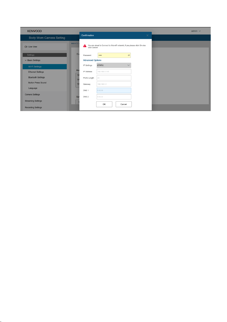
Figure 47. Web UI - Setting static Wi-Fi IP
When STATIC is selected, configure the following fields:
● IP Address
● Prefix Length
● Gateway
● DNS 1
● DNS 2
After entering the required information, click OK to save the settings and
connect to the selected Wi-Fi network.
Note:
● The BWC must be within the coverage area of the
selected Wi-Fi network.
● Ensure that the correct Wi-Fi password and network
configuration are entered. Incorrect credentials or IP
settings may prevent the BWC from connecting to the
network.
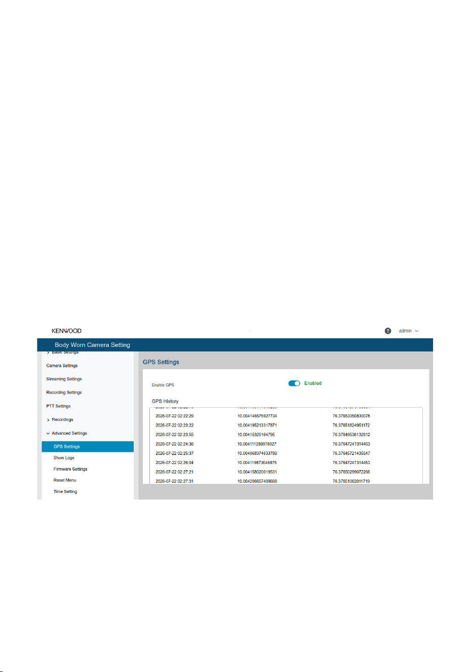
4.13. GNSS History
The GNSS History feature allows users to view the recorded GNSS location
data through the Web UI.
To access the GNSS History:
1. Log in to the Web UI.
2. Navigate to Advanced Settings > GPS Settings.
3. Use the GPS toggle switch to enable or disable the GNSS feature.
4. Once GNSS is enabled and a GPS fix is acquired, the GNSS History
section displays the recorded location details, including:
○ Timestamp
○ Latitude
○ Longitude
Note: GNSS history is updated only after the device successfully
acquires a valid GPS fix.
Figure 48. GPS History
4.13. Using Engineering Tool
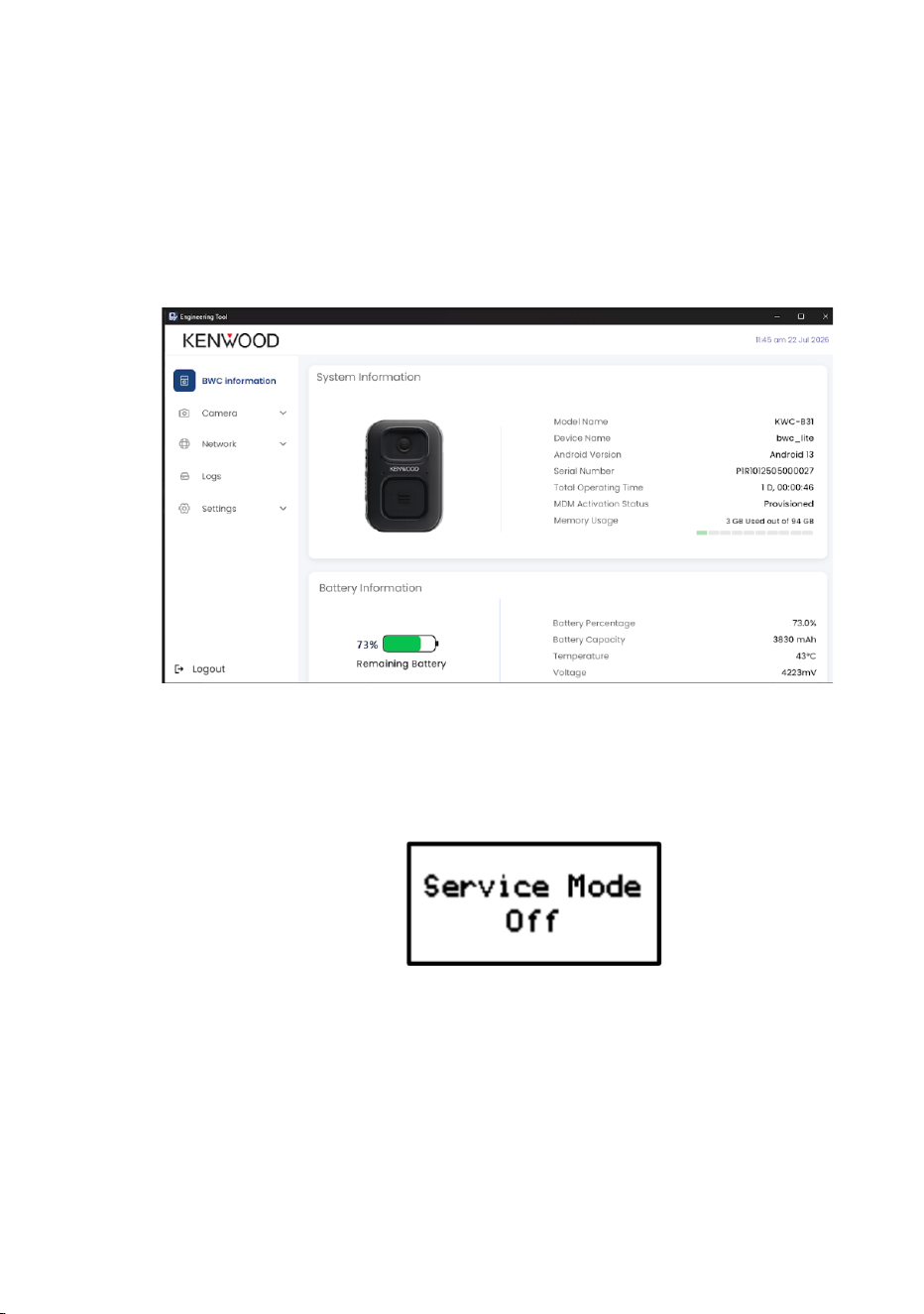
The Engineering Tool is used by service personnel to diagnose and
debug issues when the Body Worn Camera (BWC) is received at a service
station.
To access the Engineering Tool:
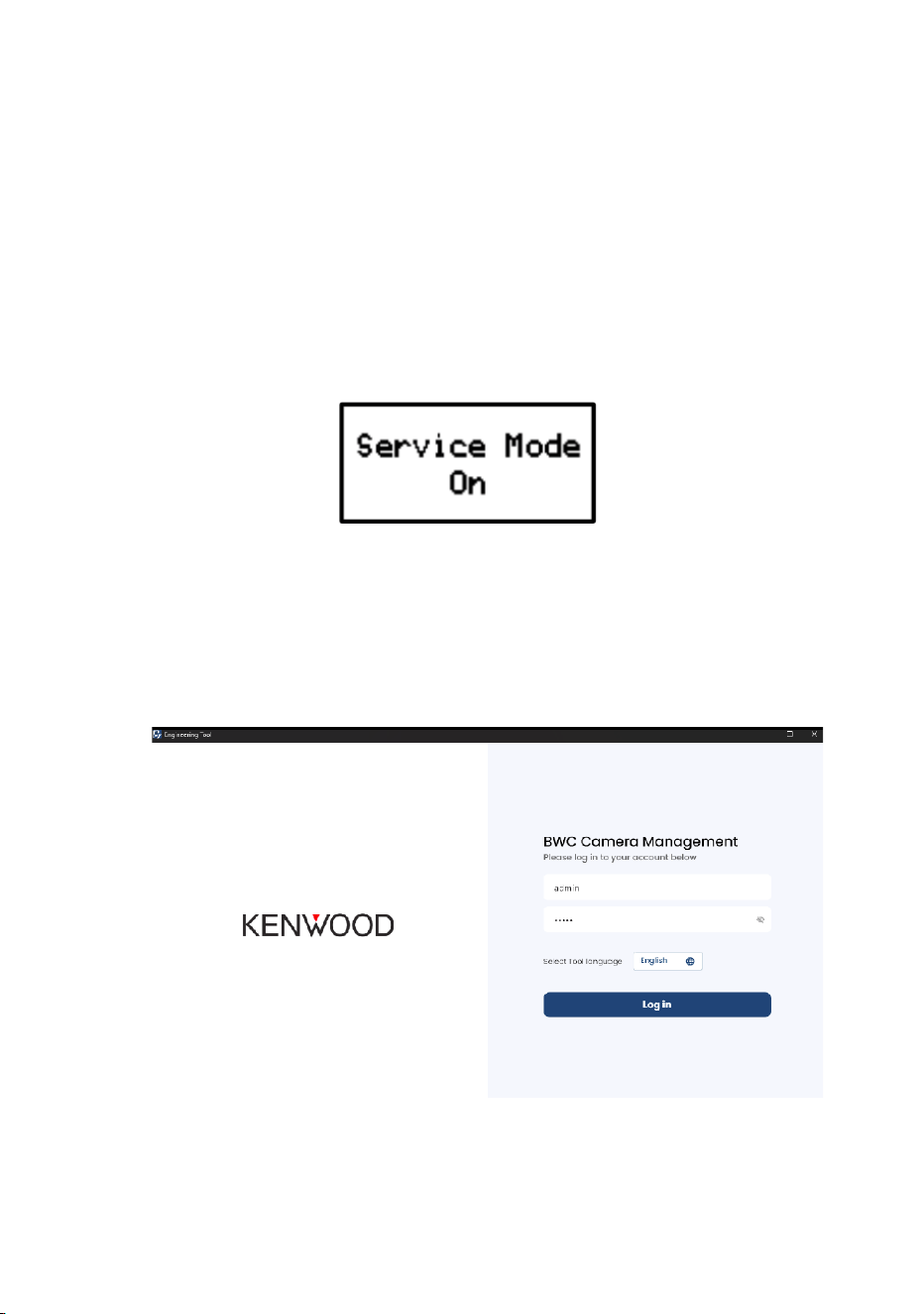
1. Enable Service Mode on the BWC by pressing and holding the Menu
and Volume Up buttons simultaneously for 5 seconds.
Figure 49. LCD Indication for service mode ON
2. Connect the BWC to a PC with the Engineering Tool installed using a
USB Type-C cable.
3. Launch the Engineering Tool on the PC. The connected BWC will be
detected.
Figure 50. Engineering Tool
4. Credentials to login are:
Username: admin
Password: admin
5. Once logged-in you can see all the information and access all the
settings from the engineering tool.
Figure 51. Engineering Tool info
6. After using the Engineering Tool, turn off Service Mode by pressing
and holding the Menu and Volume Up buttons simultaneously for 5
seconds.
Figure 52. LCD Indication for service mode OFF

5. MAINTENANCE
Proper care and maintenance of your camera device will help ensure it
continues to function optimally. Follow these guidelines for cleaning,
storing, and protecting your device.
5.1. Regular Cleaning and Maintenance
• Use a soft, lint-free cloth to gently wipe the exterior of the camera.
Avoid using abrasive materials that can scratch the surface.
• The device is rated IP54 it is protected against limited dust ingress
and splashing water from any direction.
• Do not dip the camera in water or cleaning solution
• For lens cleaning Use a lens cleaning cloth or a microfiber cloth to
gently clean the camera lens. If necessary, use a small amount of
lens cleaner (make sure it is designed for camera lenses). Avoid
using harsh chemicals or sprays directly on the lens.
• To clean the LCD display of the camera, use a damp cloth to wipe
the screen, and then dry it with a soft, dry cloth.
• Ensure that the mic and USB type- C port are free of debris
5.2. Storage Location and Temperature
• When not in use, store your camera in a cool, dry place away from
direct sunlight. Avoid storing it in areas with high humidity or extreme
temperatures.
• The recommended storage temperature is 20°C to 45°C for up to 3
months. For storage periods longer than 3 months, the temperature
should be maintained at 25°C ± 2°C, and the storage voltage should
be between 3.6 V and 3.9 V.
• Avoid storing the device near strong magnetic fields, corrosive
chemicals, or dusty environments.
• If the device will not be used for an extended period, power it off,
store it at 15°C-35°C, and perform a supplementary charge to
60-70% every two months to maintain battery health.

• Do not place heavy objects on the device or its accessories during
storage.
5.3. Battery Care
• Use the provided charger, Dock or a compatible charger to charge
the camera. Do not use cheap or uncertified chargers as they may
cause battery damage or overheat.
• Once fully charged, unplug the device from the charger.
5.4. Protect from Physical Damage
• Avoid dropping or subjecting the camera to heavy impact.
• Always use the provided mounting clip or harness to mount the
camera, and ensure that it is securely and properly mounted before
use.
5.5. Firmware and Software Maintenance
• Always keep your camera’s firmware up to date. New firmware
versions often contain bug fixes, security patches, and new features.
5.6. Handling of Docking Station
• Keep the charging dock free from dirt or debris, especially around
the connectors. Wipe the charging contacts with a soft, dry cloth if
they become dirty.
• Make sure the power adapter for the docking station is plugged in
securely and that the power cable is not damaged
5.7. Troubleshooting & Regular Maintenance
• Regularly check your camera’s functionality by ensuring that it
connects to Wi-Fi, motion detection works, and video quality is clear.
This will help catch any issues early.
• If the camera starts to behave erratically, perform a soft reset or, if
needed, a factory reset to restore it to default settings.

5.8. Important Warnings
• Do not disassemble, modify, or attempt to repair the device yourself.
Contact authorized service personnel for any servicing.
• The device contains a built-in rechargeable lithium battery, which is
not user-accessible or replaceable.
• Avoid covering or blocking the camera lens, microphone, or speaker
while operating.
• Use the camera only within the specified temperature range: –10°C
to +40°C.
6. SOFTWARE UPDATE
The firmware can be updated by uploading an OTA package to the BWC
device. The device features a web-based user interface accessible
through a web browser, allowing users to upload the OTA package
directly. USB Tethering is automatically enabled when the BWC is
connected to a PC/Laptop.
BWC will give DHCP IP to the PC and the PC will show this as an
ethernet connection.
For firmware upgrade, please follow below steps
• Login to Web UI
• Go to Advanced Settings → Firmware Information
• Click on Browse and select the file for upgrading
• Click on Upgrade
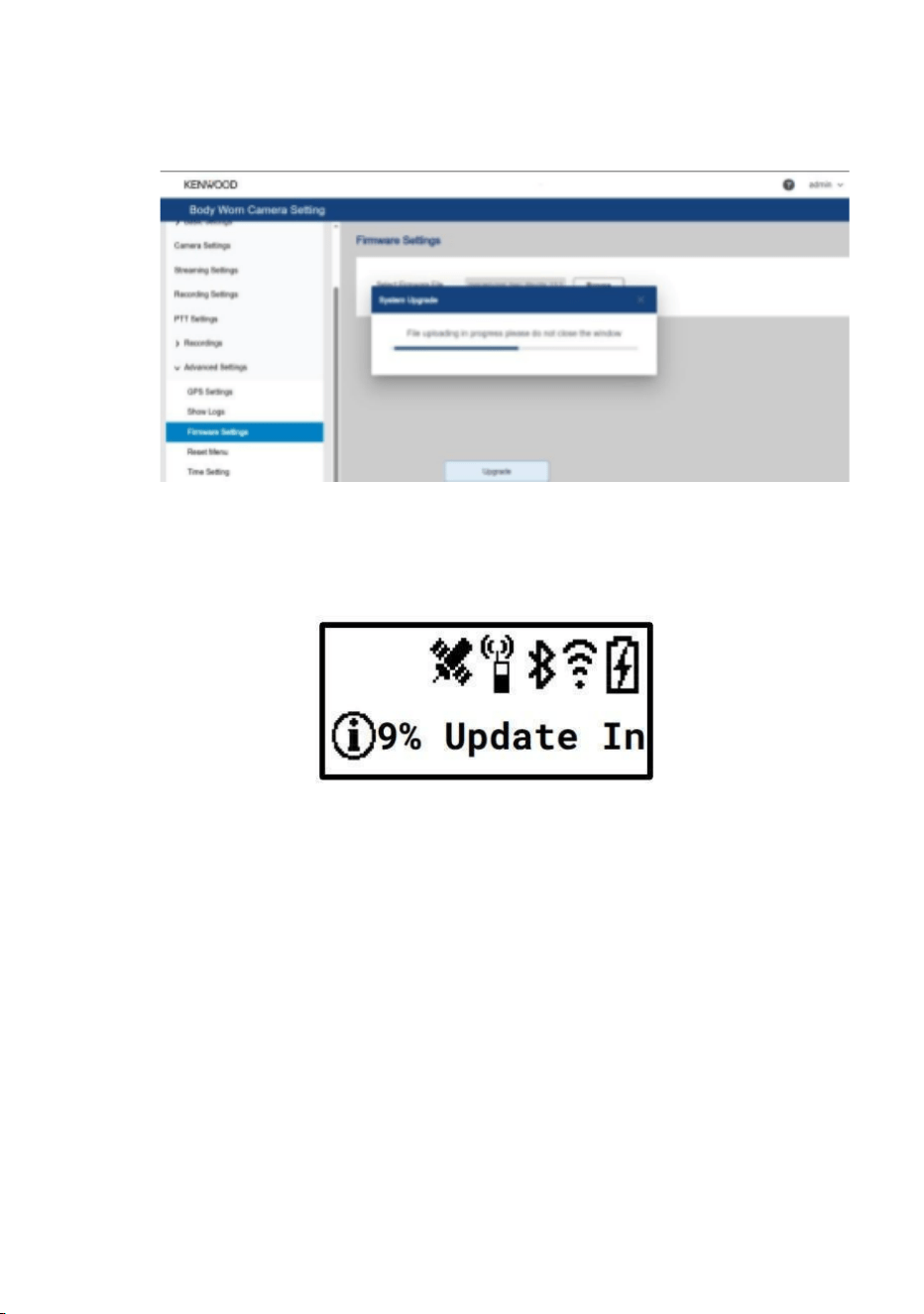
Figure 53. Web UI update initiated window
• LCD UI and Web UI will show the progress
Figure 54. LCD UI update in progress notification
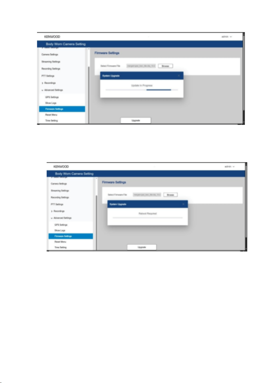
Figure 55. Web UI update initiated window
• When upgrading is finished, BWC will restart.
Figure 56. Web UI reboot window
• Once the device is booted up after a successful FW upgrade, the FW
version can be verified using Web UI or from LCD UI.
1. From Web UI
Login to Web UI
Navigate to Advanced settings > About
The FW version will be mentioned as Device Fingerprint
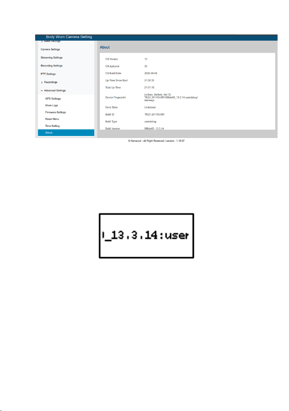
Figure 57. Web UI About page
2. From LCD UI
Press menu button
Navigate to View Status > Firmware Version
Figure 58. FW version in LCD UI
7. FAQ AND BASIC TROUBLESHOOTING
This section provides answers to the most commonly asked questions
about the camera device and offers simple solutions for minor issues.
Users can refer to this guide for quick assistance without needing
technical support. It covers topics like Wi-Fi and Bluetooth setup, motion
detection, battery charging, storage management, and firmware updates
Behaviour
What it means
What to do
Prohibit Use state
Prohibit Use
The camera is in a state
where some
malfunctions occurred
and is in a not usable
state.
Enable service mode and
then connect the device
to the Engineering tool.
Once connected the
Probit use state will be
turned OFF. ()
Behaviour
What it means
What to do
Power / Battery
Camera won’t
power on
The camera is not
turning on, possibly due
to low battery or a power
issue.
Ensure the battery is
charged or dock the
camera for charging. If
the issue persists, check
the power button or reset
the device.
Behaviour
What it means
What to do
Charging dock not
detecting camera
Yellow LED glow on
DOCK status led, means
Moisture content
detected in Type C port
Clean the Type C port,
and ensure no moisture
is present on the type c
port of both camera and
Dock
Charging dock not
detecting camera
Dirty or misaligned pogo
pins
Clean contacts with dry
cloth, Ensure correct dock
orientation and check
power adapter output.

Recording / Storage
Recording stops
automatically
Memory full or file
corruption
Check available storage
in settings, delete the
older videos from storage
Video recording
lagging or freezing
Slow or fragmented
storage
Format internal memory;
avoid frequent power-offs
during recording.
Unable to play
recorded video
Unsupported video
format on PC
Install o cial playback
software or codec pack;
export files using the
provided BWC manager
Blurry or unclear
image
Lens is dirty, fogged, or
scratched
Clean lens with microfiber
cloth; avoid touching with
fingers.
Audio
No audio in
playback
MIC covered or muted
Check mic hole for
blockage; verify MIC is
enabled in settings; test
with known good audio
clip.
Distorted or noisy
audio
Wind noise or high gain
setting
Enable noise reduction;
adjust mic gain; use
windscreen cover.
Connectivity
Wi-Fi not
connecting
The camera is not
connecting to the
network.
Check the Wi-Fi
credentials, ensure the
camera is within range of
the router, or restart both
the camera and router
Behaviour
What it means
What to do

Bluetooth not
pairing
The camera cannot
connect to a Bluetooth
device.
Delete pairing history and
re-pair; make sure
Bluetooth is enabled on
both the camera and the
device you are pairing.
Ensure both devices are
close and try again.
USB not detected
on PC while
copying
Faulty cable or driver
issue
Try another cable/port;
reinstall driver or use
Type-C data cable (not
charging-only).
System / Software
Device frozen or
unresponsive
Firmware crash
Force reboot; if issue
repeats, update firmware.
Firmware update
not working
The firmware update has
failed or is not applying.
Ensure the camera is
connected to a stable
Wi-Fi network. Restart the
camera and retry
Firmware update not
working The firmware
update has failed or is not
applying. Ensure the
camera is connected to a
stable Wi-Fi network.
Restart the camera and
retry the update. If the
issue persists, reset the
camera and try again.
The update. If the issue
persists, reset the
camera and try again.
Incorrect date/
time stamp
Date and time not set
properly
Set date/time manually
or sync via PC software.
Miscellaneous
Red LED blinking
continuously
Low battery warning or
recording error
Check battery level;
reconnect to dock; restart
device.
Table 15. FAQ and trouble shooting
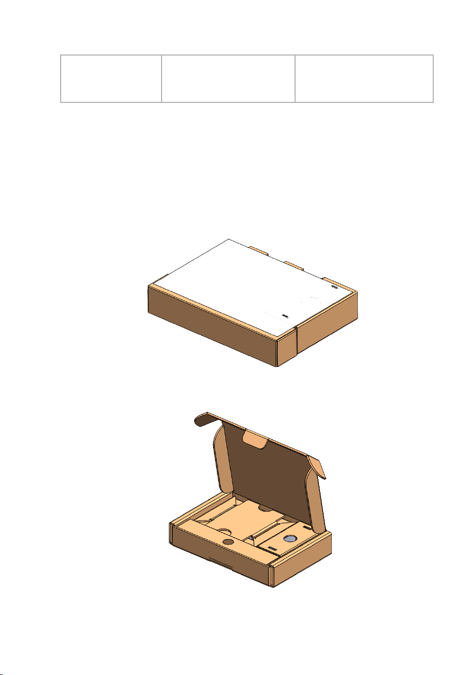
8. LITE RETAIL PACKAGING BOX
LITE retail Box :
Figure 59. LITE Individual packaging with User Manual
Figure 60.LITE box opening
Note: The final packaging should include the user manual. The above image is
shown without the user manual for reference to demonstrate the individual
packaging layout.
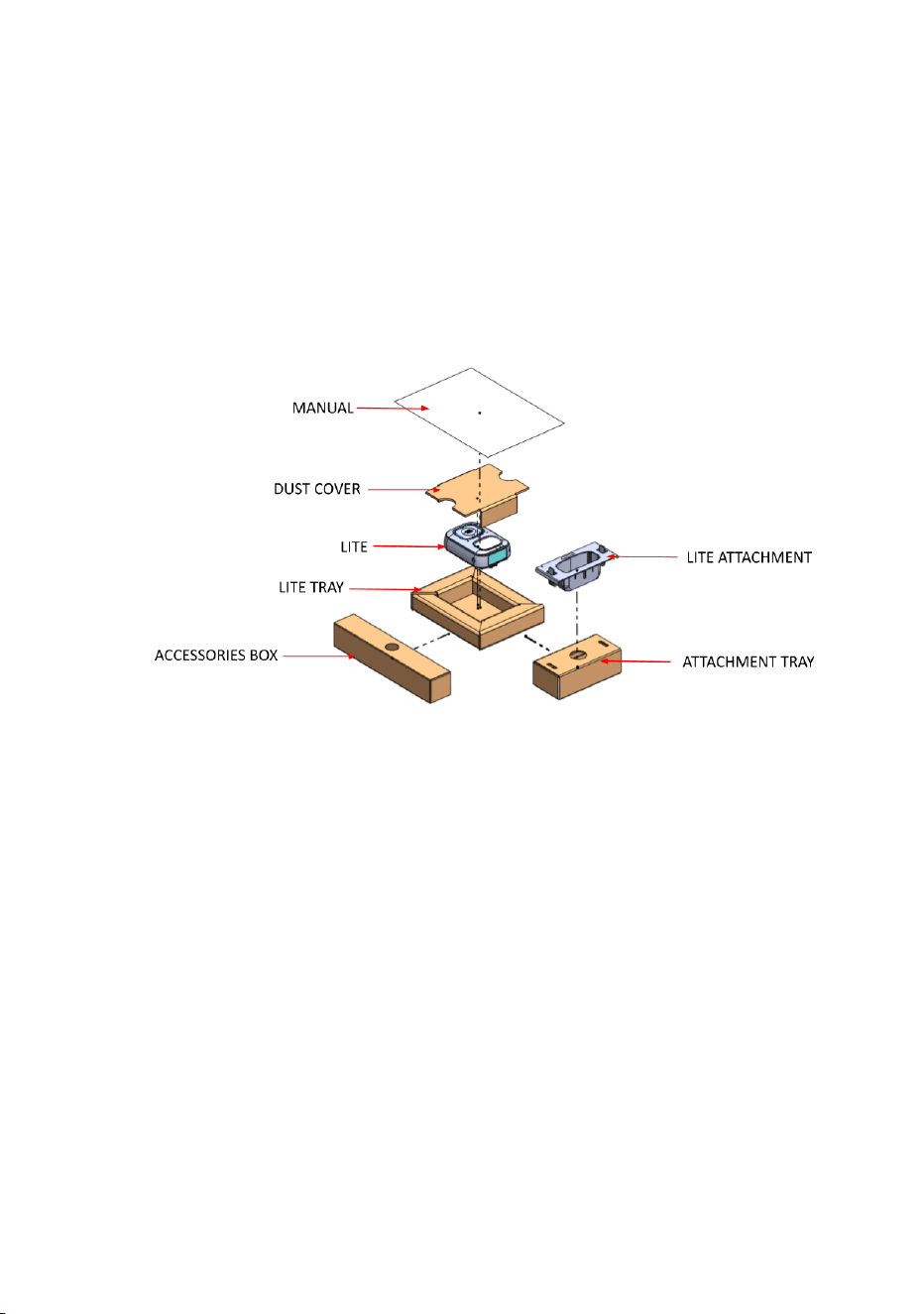
LITE retail Box contains :
Figure 61.Contents of LITE retail box
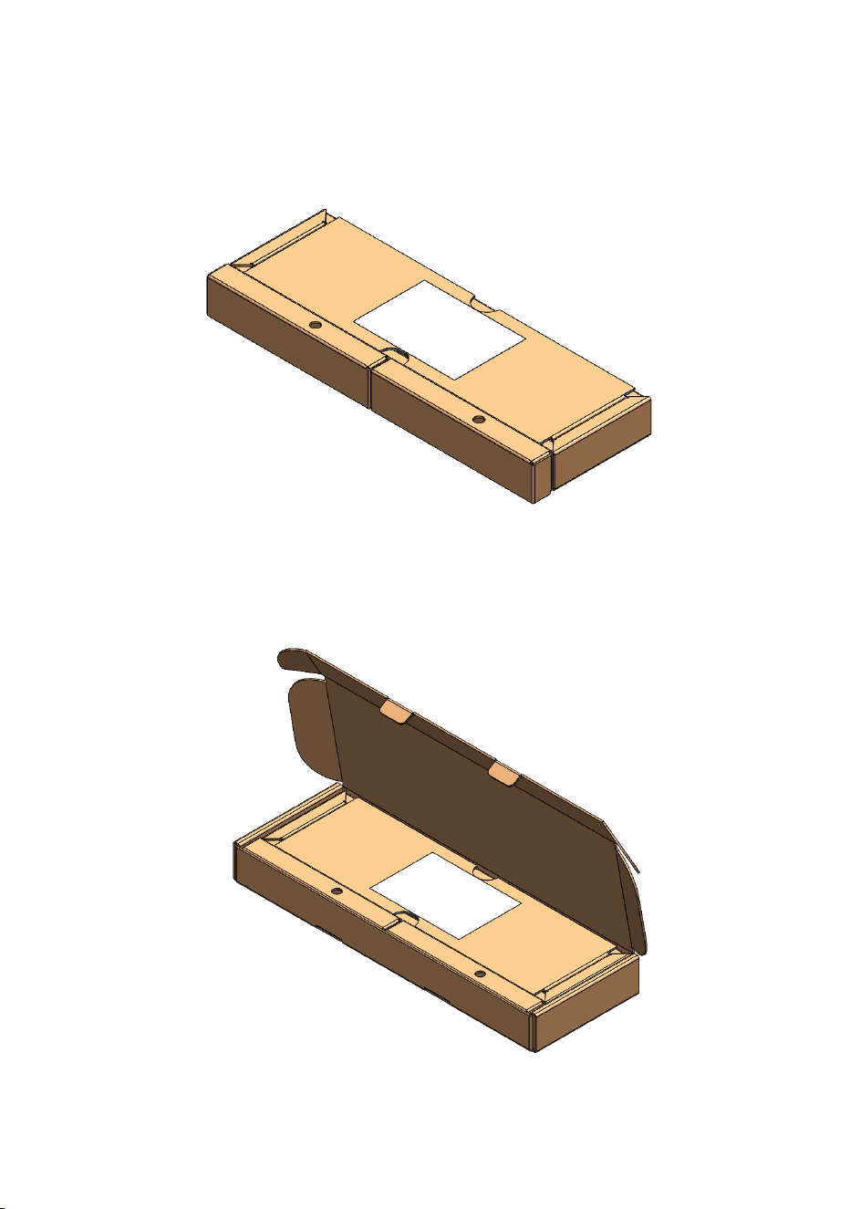
9. DOCK RETAIL PACKAGING BOX
DOCK retail Box :
Figure 62. DOCK Individual packaging with User Manual
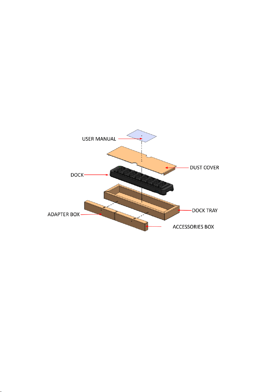
Figure 63.DOCK box opening
Note: The final packaging should include the user manual. The above image is
shown without the user manual for reference to demonstrate the individual
packaging layout.
DOCK retail Box contains :
Figure 64.Contents of DOCK retail box

CERTIFICATION FCC/IC WARNING FOR LITE
Federal Communication Commission Interference Statement
This equipment has been tested and found to comply with the limits for a Class
B digital device, pursuant to Part 15 of the FCC Rules. These limits are
designed to provide reasonable protection against harmful interference in a
residential installation.
This equipment generates, uses and can radiate radio frequency energy and, if
not installed and used in accordance with the instructions, may cause harmful
interference to radio communications. However, there is no guarantee that
interference will not occur in a particular installation. If this equipment does
cause harmful interference to radio or television reception, which can be
determined by turning the equipment off and on, the user is encouraged to try
to correct the interference by one of the following measures:
. Reorient or relocate the receiving antenna.
. Increase the separation between the equipment and receiver.
. Connect the equipment into an outlet on a circuit different from that to which
the receiver is connected.
. Consult the dealer or an experienced radio/TV technician for help.
FCC Caution: To assure continued compliance, any changes or modifications
not expressly approved by the party responsible for compliance could void the
user's authority to operate this equipment. (Example - use only shielded
interface cables when connecting to computer or peripheral devices).
RF Exposure Information (SAR):
This device meets the government’s requirements for exposure to radio waves.
This device is designed and manufactured not to exceed the emission limits for

exposure to radio frequency (RF) energy set by the Federal Communications
Commission of the U.S. Government.
The exposure standard for wireless devices employing a unit of measurement
is known as the Specific Absorption Rate, or SAR. The SAR limit set by the
FCC is W/kg.
This device complies with Part 15 of the FCC Rules. Operation is subject to the
following two conditions:
(1) This device may not cause harmful interference, and (2) This device must
accept any interference received, including interference that may cause
undesired operation.
Industry Canada Statement
This device complies with Industry Canada licence-exempt RSS standard.
Operation is subject to the following two conditions: (1) this device may not
cause interference, and (2) this device must accept any interference, including
interference that may cause undesired operation of the device.
Le présent appareil est conforme aux CNR d'Industrie Canada applicables aux
appareils radio exempts de licence. L'exploitation est autorisée aux deux
conditions suivantes : (1) l'appareil ne doit pas produire de brouillage, et (2)
l'utilisateur de l'appareil doit accepter tout brouillage radioélectrique subi, même
si le brouillage est susceptible d'en compromettre le fonctionnement.
IC RF Exposure Information (SAR):

This device meets the government’s requirements for exposure to radio waves.
This device is designed and manufactured not to exceed the emission limits for
exposure to radio frequency (RF) energy set by the Federal Communications
Commission of the U.S. Government.
The exposure standard for wireless devices employing a unit of measurement
is known as the Specific Absorption Rate, or SAR. The SAR limit set by the IC
is W/kg.
Cet appareil est conforme aux exigences du gouvernement en matière
d'exposition aux ondes radio.
Cet appareil est conçu et fabriqué de manière à ne pas dépasser les limites
d'émission pour l'exposition à l'énergie de radiofréquence (RF) établies par la
Federal Communications Commission (FCC) du gouvernement des É
tats-Unis. La norme d'exposition pour les appareils sans fil utilise une unité de
mesure appelée debit d'absorption spécifique, ou SAR. La limite SAR établie
par la IC est de W/kg.
______________________________________