
© Copyright by Airspan Networks Ltd., 2026. All rights reserved worldwide.
ATG CALLBOX UI INSTALLATION AND
TEST MANUAL
USER MANUAL
Document Part Number: SYN-UG-050
Version: Rev I
Published: Aug 2026

ATG Callbox UI installation and Test manual
user manual
© Copyright Airspan Networks Ltd., 2026 P/N: SYN-UG-050 Rev I, Aug 2026
i
© Copyright by Airspan Networks Ltd., 2024-2025. All rights reserved worldwide.
Legal Notices
The information contained within this document is proprietary, privileged and intended only for the recipient. As such, the
information is subject to all relevant copyright, patent and other laws protecting intellectual property, as well as any
specific agreements protecting Airspan Networks Ltd. rights in the aforesaid information. Neither this document nor the
information contained herein may be published, reproduced, transmitted or disclosed to third parties, in whole or in part,
without the express, prior, written permission of Airspan Networks Ltd. In addition, any use of this document or the
information contained herein for the purposes other than those for which it is disclosed is strictly forbidden.
Airspan Networks Ltd. reserves the right, without prior notice or liability, to make changes in equipment design or
specifications.
Information supplied by Airspan Networks Ltd. is believed in good faith to be accurate and reliable, while every care has
been taken in preparing these documents. However, Airspan Networks Ltd. does not make any representations and gives
no warranties of whatever nature in respect of these documents, including without limitation, the accuracy or
completeness of any information, facts and/or opinions contained therein. No responsibility is assumed by Airspan
Networks Ltd. for the use of the documents nor for the rights of third parties which may be effected in any way by the use
thereof. The provision of these documents (and the documents themselves) does not constitute professional advice of any
kind. Any representation(s) in these documents concerning performance of Airspan Networks Ltd. product(s) are for
informational purposes only and are not warranties of future performance, either expressed or implied. Airspan Networks
Ltd., its affiliates, directors, employees and agents shall not be held liable for any damages or losses, of any nature
whatsoever, arising from any use of and/or reliance on the documents.
These documents may contain flaws, omissions or typesetting errors; no warranty is granted nor liability assumed in
relation thereto unless specifically undertaken in Airspan Networks Ltd. sales contract or order confirmation. Information
contained herein is periodically updated and changes will be incorporated into subsequent editions. If you have
encountered an error, please notify Airspan Networks Ltd.
Product performance figures quoted within this document are indicative and for information purposes only.
UK WEEE Registration number: WEEE/AB0207WZ. For more information, see WEEE Information for Airspan Customers and
Recyclers.

ATG Callbox UI installation and Test manual
user manual
© Copyright Airspan Networks Ltd., 2026 P/N: SYN-UG-050 Rev I, Aug 2026
ii
CONTENTS
Document Information ............................................................................................... 1
Revision History ...................................................................................................................... 1
About This Document ................................................................................................. 2
1.1 Intended Audience .................................................................................................... 2
1.2 Open issues................................................................................................................ 2
1.3 Terminology ............................................................................................................... 4
1.4 References ................................................................................................................. 4
2 Physical layout ............................................................................................................ 5
3 Installation .................................................................................................................. 6
4 Test Setup ................................................................................................................... 8
4.1 Connectivity ............................................................................................................... 8
4.2 Configuration ............................................................................................................. 8
4.2.1 password.gpg ......................................................................................................... 8
4.2.2 ue_db_gogo.conf .................................................................................................... 9
4.2.3 ascb.conf: ............................................................................................................... 9
4.3 Execution ................................................................................................................. 11
4.4 Log files .................................................................................................................... 14
4.4.1 Callbox logs .......................................................................................................... 14
4.4.2 User test logs ........................................................................................................ 14
4.5 Tests ........................................................................................................................ 15
5 Regulatory ................................................................................................................. 37
5.1 Human Exposure to Radio Frequencies ................................................................... 37
5.2 FCC Statements ....................................................................................................... 37

ATG Callbox UI installation and Test manual
user manual
© Copyright Airspan Networks Ltd., 2026 P/N: SYN-UG-050 Rev I, Aug 2026
iii
Figure 1: Search for Secure Boot ............................................................................................................. 2
Figure 2: Select Disabled option .............................................................................................................. 3
Figure 3: Exit ............................................................................................................................................ 3
Figure 4: Save & Exit ................................................................................................................................ 4
Figure 5: Physical layout .......................................................................................................................... 5
Figure 6: Software package ..................................................................................................................... 6
Figure 7: Installation ................................................................................................................................ 7
Figure 8: Credentials ............................................................................................................................... 8
Figure 9: UE Information ......................................................................................................................... 9
Figure 10: If ascb.conf and Callbox configs are correct then above window appears ........................... 11
Figure 11: Execution .............................................................................................................................. 11
Figure 12: Callbox login credentials are wrong in password.gpg ........................................................... 12
Figure 13: Wrong pci value configured in ascb.conf file ........................................................................ 12
Figure 14: Valid PCI list .......................................................................................................................... 13
Figure 15: Test Result ............................................................................................................................ 14
Figure 16: Start Cell button ................................................................................................................... 15
Figure 17: UE list .................................................................................................................................... 15
Figure 18: Cell starts failed due to invalid gain value ............................................................................ 16
Figure 19: All the editable config freeze till cell stop ............................................................................. 16
Figure 20: Start Cell button ................................................................................................................... 17
Figure 21: Cell started with valid configuration ..................................................................................... 17
Figure 22: Cell starts failed due to invalid gain value ............................................................................ 18
Figure 23: All the editable config freeze till cell stop ............................................................................. 18
Figure 24: Cell start checkbox used to stop cell .................................................................................... 19
Figure 25: Cell stopped .......................................................................................................................... 19
Figure 26: Cell start checkbox used to stop cell .................................................................................... 20
Figure 27: Cell stopped .......................................................................................................................... 20
Figure 28: Update attenuation .............................................................................................................. 21
Figure 29: Cell started with updated operational attenuation .............................................................. 22
Figure 30: Update cell id........................................................................................................................ 23
Figure 31: Cell started with updated cell id ........................................................................................... 23
Figure 32: Start Iperf server................................................................................................................... 24
Figure 33: Iperf server started on Callbox ............................................................................................. 24
Figure 34: Failed to start iperf server on Callbox ................................................................................... 25
Figure 35: Get Iperf Log button ............................................................................................................. 25
Figure 36: No data to display ................................................................................................................. 26
Figure 37: Get Iperf Log fetches last iperf test result ............................................................................ 26
Figure 38: Core selection ....................................................................................................................... 27
Figure 39: Connected UE List button disappears if cell not started ...................................................... 28
Figure 40: Connected UE List button appears as cell started successfully ............................................ 28
Figure 41:Connected UE List data ......................................................................................................... 29
Figure 42: MME UE data block and eNB UE data block ......................................................................... 29
Figure 43: Close the application ............................................................................................................ 30
Figure 44: Poweroff the Callbox ............................................................................................................ 31
Figure 45: Poweroff the Callbox request received ................................................................................ 31
Figure 46: Callbox performing poweroff command .............................................................................. 32
Figure 47: Searching for Callbox ............................................................................................................ 32
Figure 48: Callbox Poweroff request processed successfully; now Callbox offlin. ................................. 33
Figure 49: Callbox still offline ................................................................................................................ 33
Figure 50: Callbox online now ............................................................................................................... 34

ATG Callbox UI installation and Test manual
user manual
© Copyright Airspan Networks Ltd., 2026 P/N: SYN-UG-050 Rev I, Aug 2026
iv
Figure 51: Minor UI Corrections ............................................................................................................ 34
Figure 52: Keep Online unchecked ........................................................................................................ 35
Figure 53: Keep Online checked ............................................................................................................ 35
Figure 54: t & t spl output ..................................................................................................................... 36
Figure 55: Desktop Shortcut .................................................................................................................. 36

ATG Callbox UI installation and Test manual
– user manual
© Copyright Airspan Networks Ltd., 2026 P/N: EVO084-SW-0008 Rev I, Aug 2026
1
Document Information
Revision History
Revision Date Summary of Changes Created by
Rev A December 2025 Initial release Tushar
Tupe
Rev B December 2025 Template update
Ashvtosh
Goel
Rev C January 2026 Updated for new UI, V1.5 Tushar/Ash
vtosh
Rev D February 2026 Updated for UI update V1.6 Tushar
Tupe
Rev E February 2026 Minor UI correction, V1.7
Tushar
Tupe
Rev F March 2026 UI feature updates, V1.9 Tushar
Rev G April 2026 UI feature updates, Physical Layout Tushar
Rev H July 2026 Added Minimum Safe Operating Distance Stuart
Parrott
Rev H August 2026 FCC part 15 statements added Charlie
Blackham
ATG Callbox UI installation and Test manual
– user manual
© Copyright Airspan Networks Ltd., 2026 P/N: EVO084-SW-0008 Rev I, Aug 2026
2
About This Document
This document specifies the interface and control requirements between the 2.4G and
DMA Aircard software and the ATG platform host for the ATG Evolution project.
1.1 Intended Audience
This document is intended for user performing the tests with callbox in Gogo and clients network.
1.2 Open issues
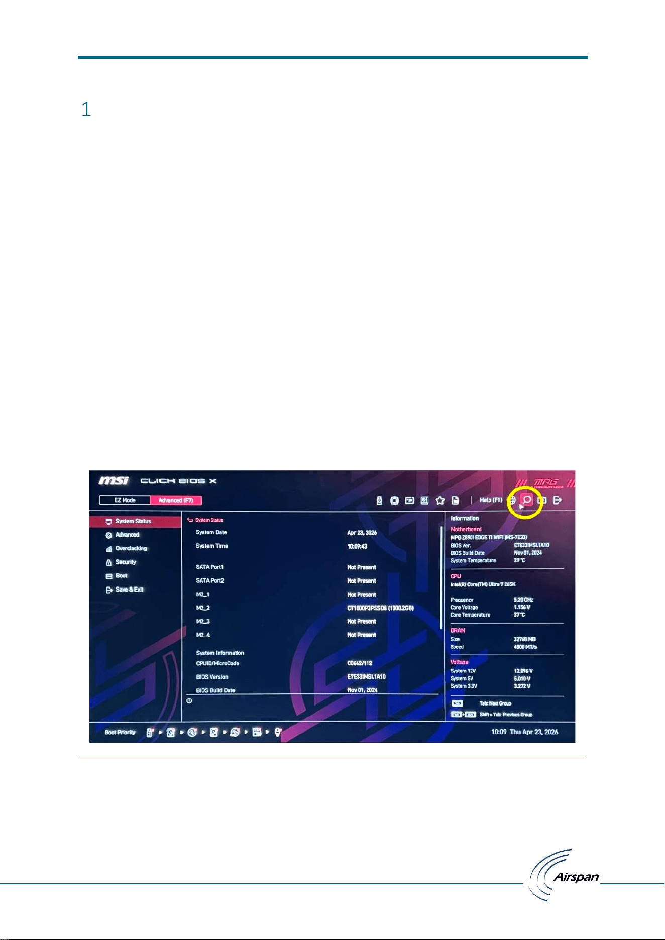
Sometimes the Callbox motherboard enables secure boot option leads to failure in external ethernet
interface card [enp4s0] detection. This can be identified when UI application starts and reports all
the interfaces.
To recover from this, a monitor/keyboard/mouse needs to be attached and reconfigure boot options
as follows:
1. Enter boot mode:
Press ‘Delete’ key during boot.
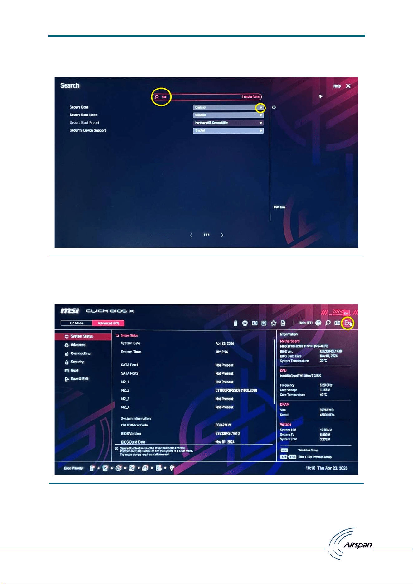
2. Search for Secure Boot option:
Search for Secure boot in search tool.
Figure 1: Search for Secure Boot
ATG Callbox UI installation and Test manual
– user manual
© Copyright Airspan Networks Ltd., 2026 P/N: EVO084-SW-0008 Rev I, Aug 2026
3
3. Disable Secure Boot:
Select Disabled option in dropdown.
Figure 2: Select Disabled option
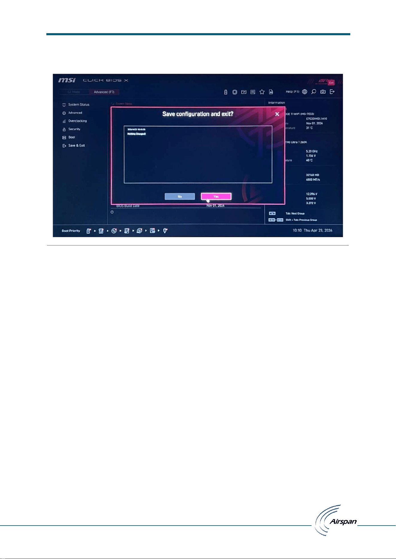
4. Click on Exit button:
Click on Exit button.
Figure 3: Exit
ATG Callbox UI installation and Test manual
– user manual
© Copyright Airspan Networks Ltd., 2026 P/N: EVO084-SW-0008 Rev I, Aug 2026
4
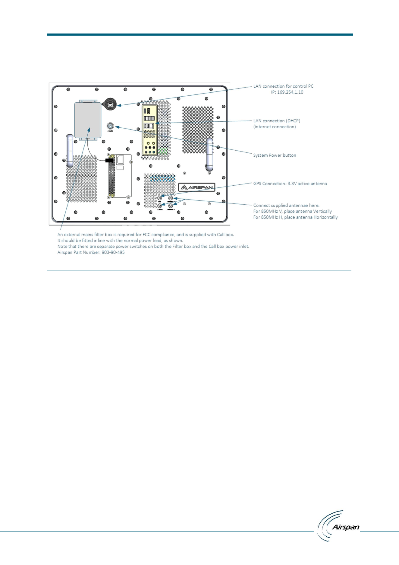
5. Save & Exit:
Click on Yes button to save configuration & exit from boot mode.
Figure 4: Save & Exit
1.3 Terminology
Callbox: a single box hosting enodeb and gnodeb services
Host PC: A PC with ubuntu22 which will execute the UI.
1.4 References
1.
ATG Callbox UI installation and Test manual
– user manual
© Copyright Airspan Networks Ltd., 2026 P/N: EVO084-SW-0008 Rev I, Aug 2026
5
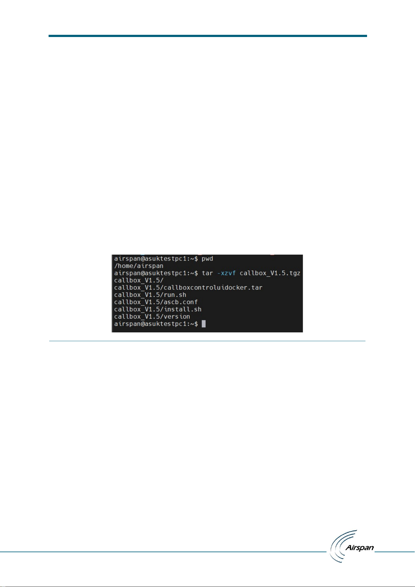
2 Physical layout
Figure 5: Physical layout
ATG Callbox UI installation and Test manual
– user manual
© Copyright Airspan Networks Ltd., 2026 P/N: EVO084-SW-0008 Rev I, Aug 2026
6
3 Installation
Callbox UI Tarball installation: Target – Test host PC
Basic system requirement for Host PC: Ubuntu 22.04
Basic requirement for test user: user should be part of sudoers for installation of the docker and
software. User will be added to docker group during installation to avoid any further permission
issues.
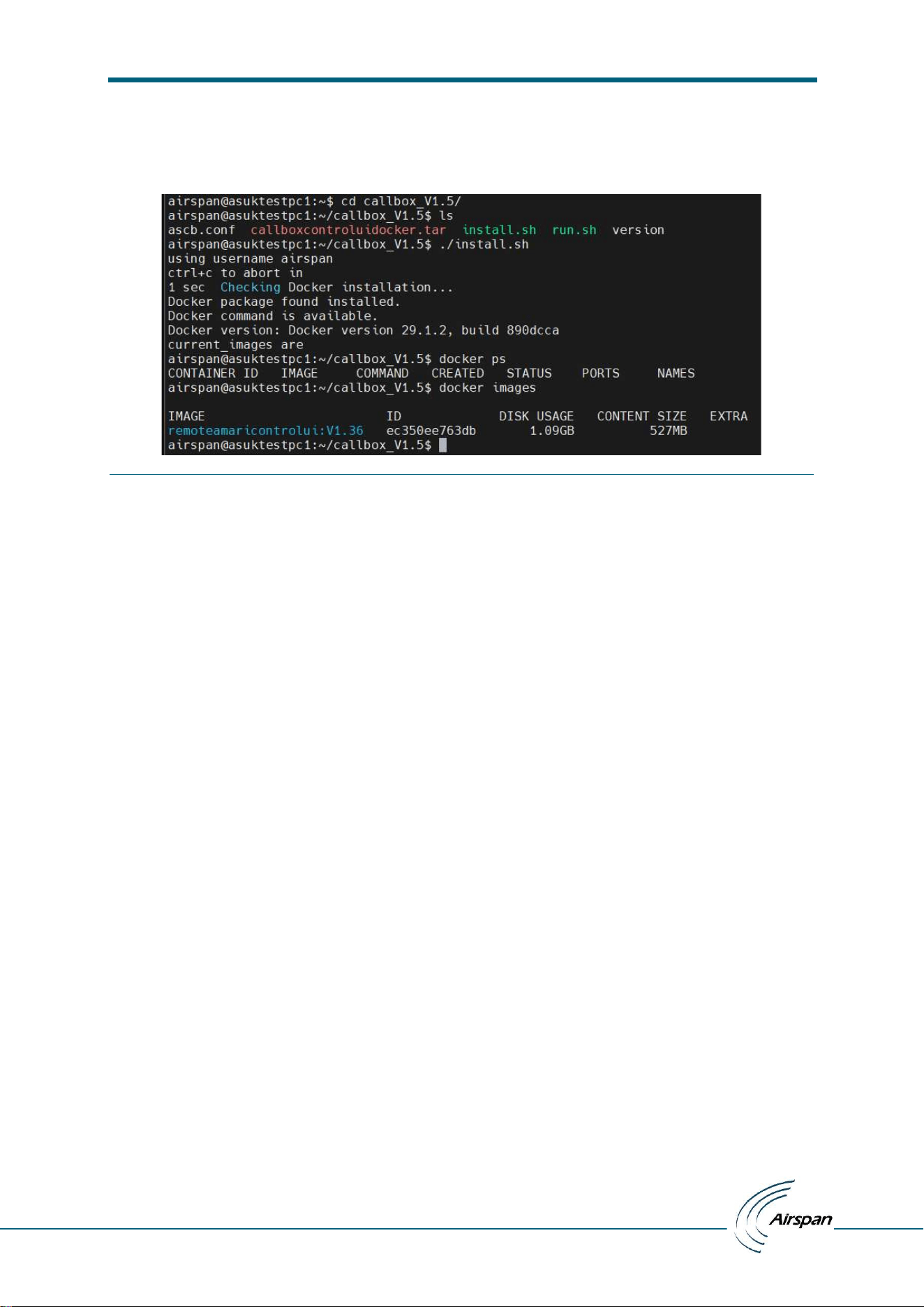
Release artifact: callbox_Vx.xx.tgz
Tarball content
1 version : package version
2 ascb.conf: Configuration file for IP addresses, iperf ports, eNodeB ID, gNodeBID, Cell ID, PCI
etc
3 install.sh : script to install docker packages
4 callboxcontroluidocker.tar : docker with software
5 run.sh : executution script
User should untar the software release tarball in home directory.
Figure 6: Software package
ATG Callbox UI installation and Test manual
– user manual
© Copyright Airspan Networks Ltd., 2026 P/N: EVO084-SW-0008 Rev I, Aug 2026
7
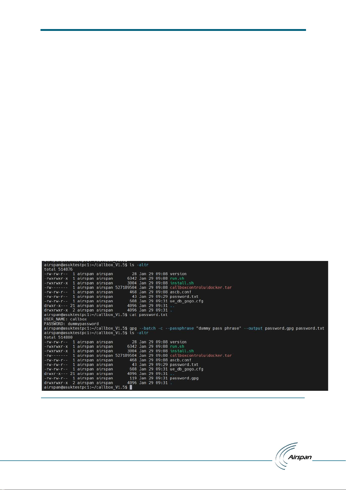
User should execute install.sh to install the docker environment. It is preferred to run with every
release. This would also delete any old docker callbox ui image.
Figure 7: Installation
Note1: If docker is installed for the first time, user should logout and login again before execution.
Note2: Callbox should be connected to internet to install docker packages if not present already.
ATG Callbox UI installation and Test manual
– user manual
© Copyright Airspan Networks Ltd., 2026 P/N: EVO084-SW-0008 Rev I, Aug 2026
8
4 Test Setup
4.1 Connectivity
The callbox should be accessible to the test host PC over IPv4 ssh. The callbox is expected to have
two ethernet interfaces, one with DHCP and one with static IP(v4) 169.254.1.10. If callbox network
configuration changes, the configuration must be updated accordingly. See following section for the
config files.
4.2 Configuration
Following are the config files required to start/control the UI application and callbox
4.2.1 password.gpg
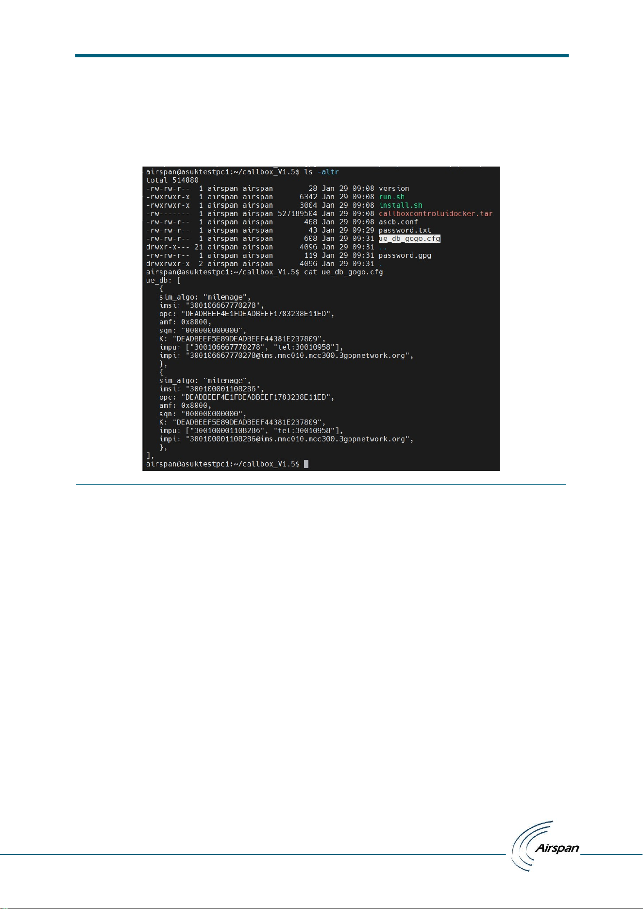
The release docker comes with a password.gpg file which corresponds to the default
username/password of the callbox. If the callbox password is updated, this file must be updated in
the untarred release folder.
To create the gpg key file, create a password file with below content in <tag>: <value> format (user
should update password with target machine credentials)
USER_NAME: callbox
PASSWORD: <password>
and run following command to create encrypted password.gpg file using above credentials
$ gpg --batch -c --passphrase <pass phrase> --output password.gpg /tmp/password
Figure 8: Credentials
ATG Callbox UI installation and Test manual
– user manual
© Copyright Airspan Networks Ltd., 2026 P/N: EVO084-SW-0008 Rev I, Aug 2026
9
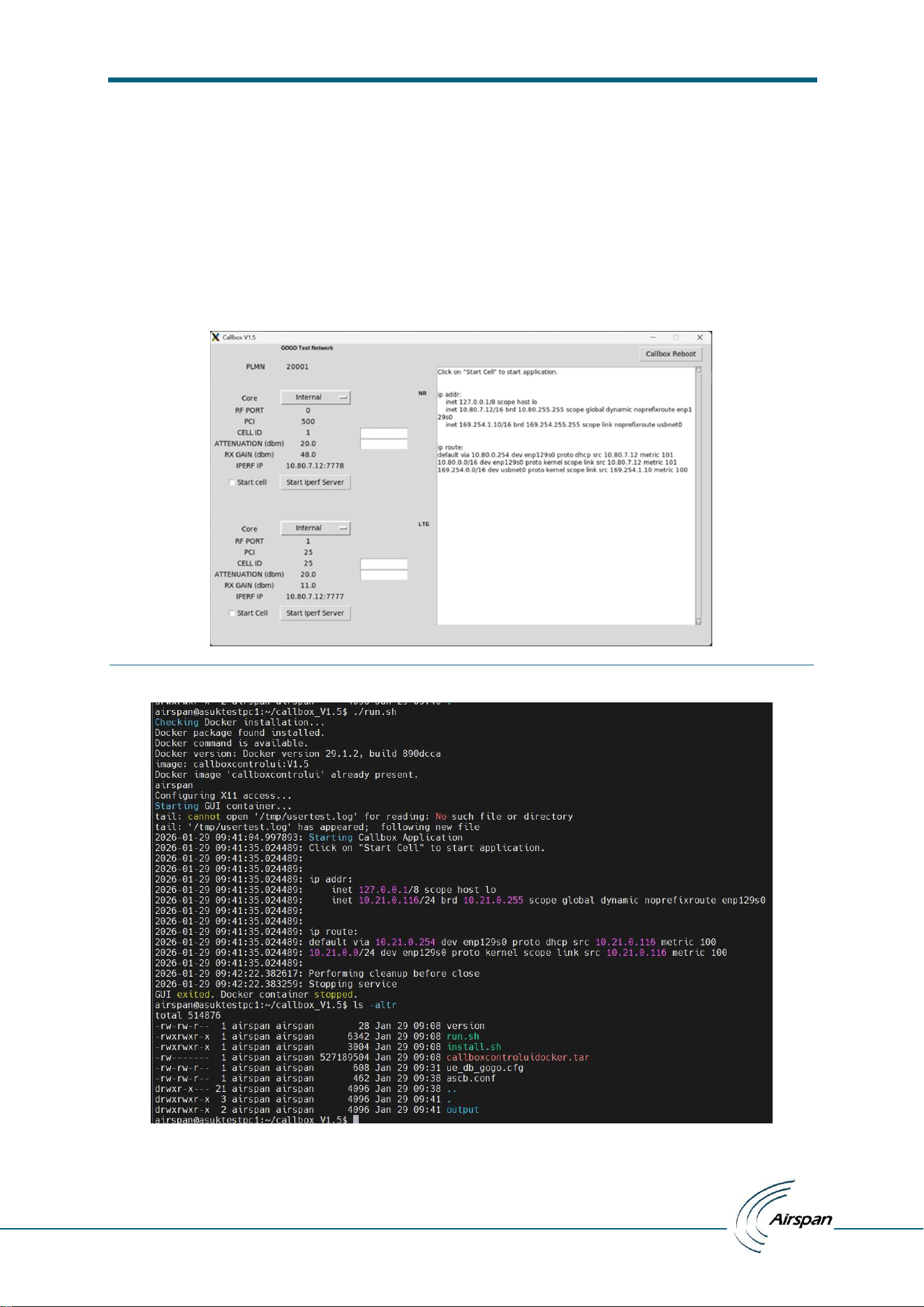
4.2.2 ue_db_gogo.conf
This file is needed locally if the callbox internal core is used. This should have sim related info for the
aircards which needs to be connected.
Figure 9: UE Information
4.2.3 ascb.conf:
This file is supplied in the tarball with some default parameters and must be updated before starting
the UI. These are configuration values to start and control the operation of callbox provided in <tag:
value> format. User should change the param values as per current system.
This file lists all the expert UI configurable values that can be used to set / change the parameters
like callbox ip, mme ip, amf ip, gtp address, ngap bind address, iperf server ip & port, plmn, enb id,
gnb id, lte/nr cell attenuation, rx gain, pci, cell id, gps less operation, tac, nssai sst/sd & ssb nr arfcn
of NR cell.
CALLBOX_IP: 169.254.1.10
MME_IP: 127.0.0.1
AMF_IP: 10.80.0.7
GTP_ADDR: 10.80.6.254
NGAP_BIND_ADDR: 10.80.6.254
IPERF_SERVER_IP: 10.80.6.254
IPERF_SERVER_PORT_4G: 7777
IPERF_SERVER_PORT_5G: 7778
PLMN: 31000
ENB_ID: 0x1
GNB_ID: 0x12345
CELL_ATTENUATION_4G: 20
CELL_ATTENUATION_5G: 55
ENB_RX_GAIN_P1: 20.0

ATG Callbox UI installation and Test manual
– user manual
© Copyright Airspan Networks Ltd., 2026 P/N: EVO084-SW-0008 Rev I, Aug 2026
10
ENB_RX_GAIN_P2: 20.0
GNB_RX_GAIN_P0: 44.0
LTE_CELL_ID: 25
PCI: 25
NR_CELL_ID: 2
PCI_5G: 2
TAC_4G: 10
TAC_5G: 10
GNB_SSB_NR_ARFCN: 495150
NSSAI_SST: 1
INCLUDE_NSSAI: 1
NSSAI_SD: 000001
OPERATION_WITH_GPS: 1
Note1: an output directory is created when executing the UI with application debug and test logs.
This folder also has some configuration files which are generated from the input config files. If
ascb.conf file needs to be updated, both cells should be stopped if running, the application should be
stopped, final_ascb.conf from output needs to be removed and then application should be started
again.
Note2: Since the SDR card output is connected to the FEM, the TX power from SDR card should be
increased cautiously as it may burn the FEM. This power is controlled through CELL Attenuation
values [CELL_ATTENUATION_4G/ CELL_ATTENUATION_5G]. The current limit in software is set to
minimum of 10dB. Please do not try to set a lower attenuation.
ATG Callbox UI installation and Test manual
– user manual
© Copyright Airspan Networks Ltd., 2026 P/N: EVO084-SW-0008 Rev I, Aug 2026
11
4.3 Execution
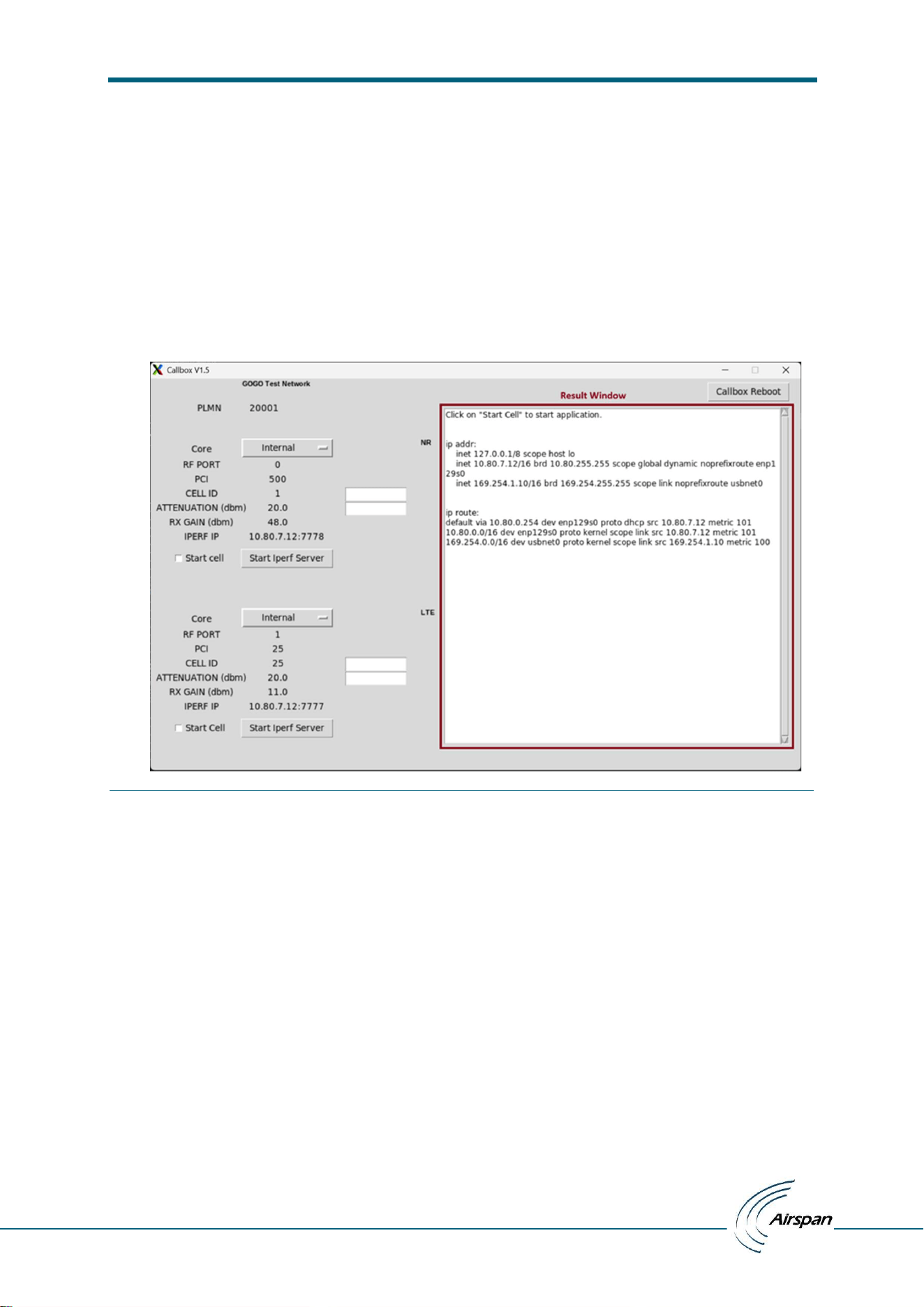
To start the UI, user should change dir to release directory and use run.sh script from this directory.
$./run.sh
This would start the traces on same console, and a UI window will pop up. An output directory will
be created when the UI is started. It will have configuration files used by application within docker
container. UI will also generate log files in this directory.
Figure 10: If ascb.conf and Callbox configs are correct then above window appears
Figure 11: Execution
ATG Callbox UI installation and Test manual
– user manual
© Copyright Airspan Networks Ltd., 2026 P/N: EVO084-SW-0008 Rev I, Aug 2026
12
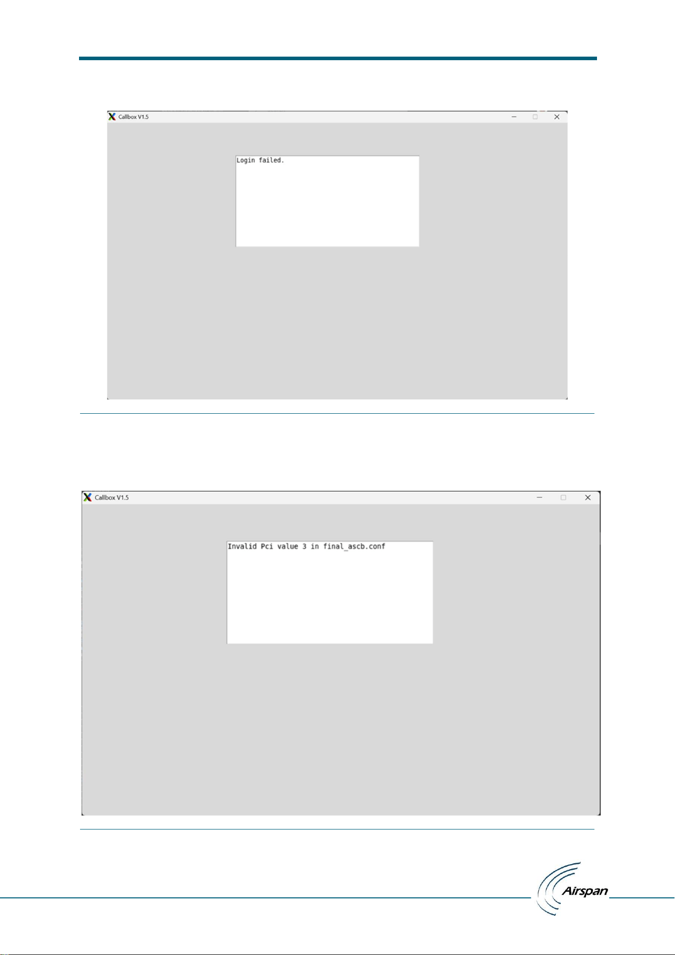
For login failure with invalid credentials supplied from password.gpg file:
Figure 12: Callbox login credentials are wrong in password.gpg
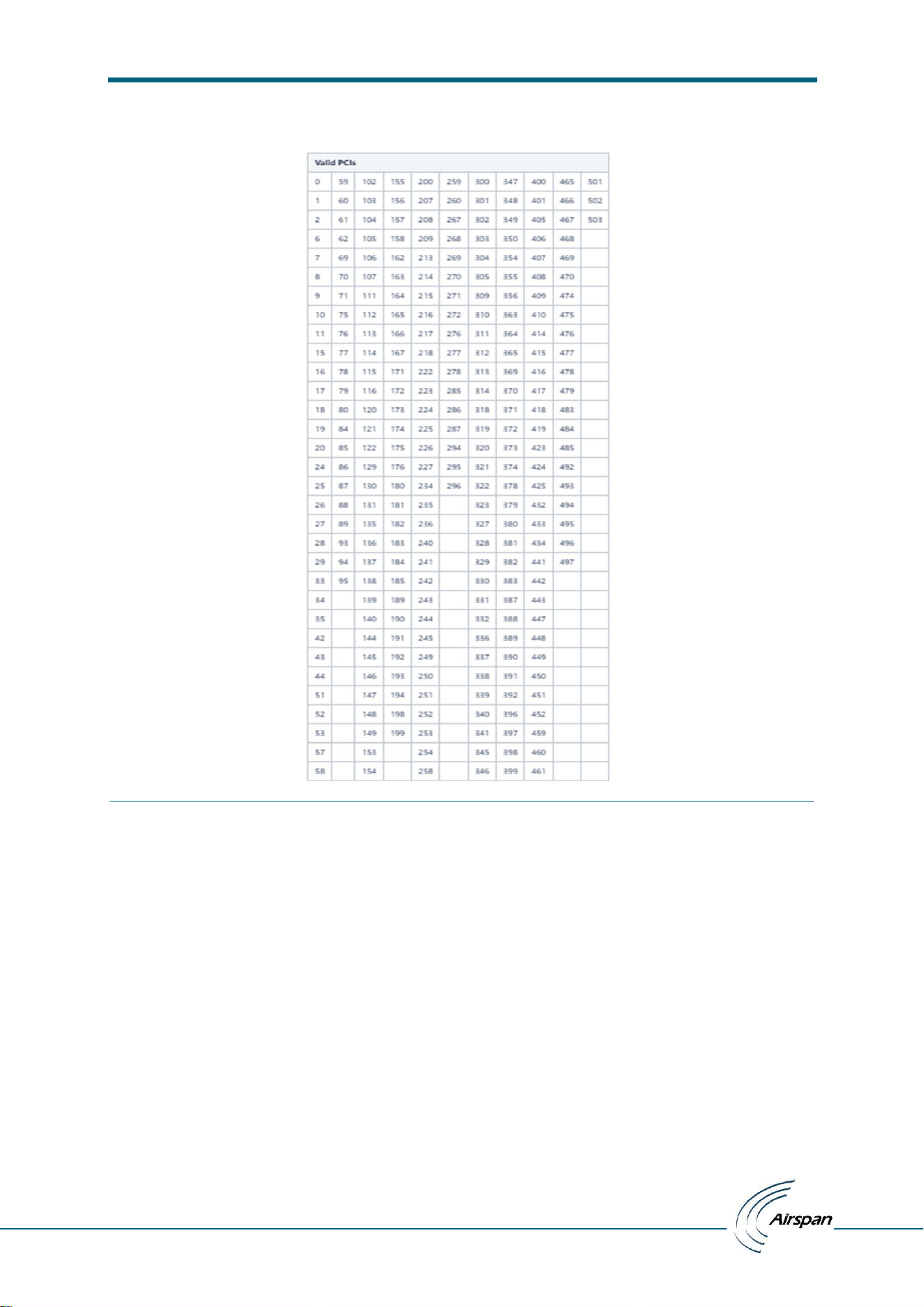
For invalid PCI value supplied from ascb.conf file:
Figure 13: Wrong pci value configured in ascb.conf file
ATG Callbox UI installation and Test manual
– user manual
© Copyright Airspan Networks Ltd., 2026 P/N: EVO084-SW-0008 Rev I, Aug 2026
13
List of valid PCI’s:
Figure 14: Valid PCI list
ATG Callbox UI installation and Test manual
– user manual
© Copyright Airspan Networks Ltd., 2026 P/N: EVO084-SW-0008 Rev I, Aug 2026
14
4.4 Log files
4.4.1 Callbox logs
All the Callbox logs will be redirected to output/callbox.log file. File contains all the debug logs, info logs and
error logs with timestamp
4.4.2 User test logs
All the user test results will be seen in the output window in the UI and also redirected to output/usertest.log
file with timestamp
Figure 15: Test Result
ATG Callbox UI installation and Test manual
– user manual
© Copyright Airspan Networks Ltd., 2026 P/N: EVO084-SW-0008 Rev I, Aug 2026
15
4.5 Tests
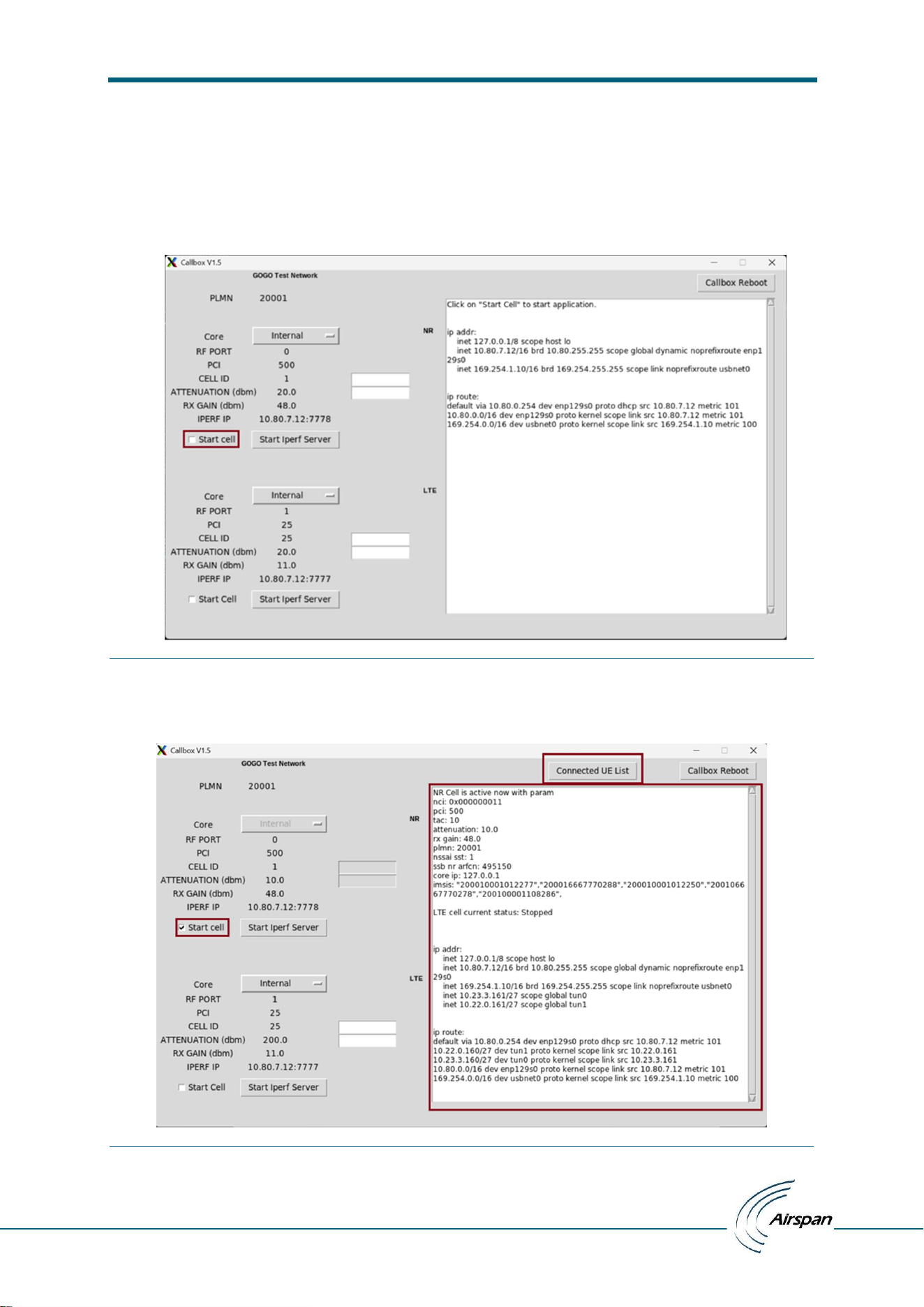
The UI supports following options for the user to start callbox
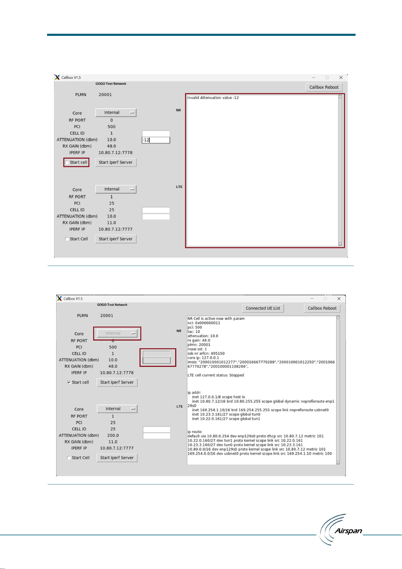
1. Start 5G/NR Cell:
Now click on ‘Start Cell’ button to start 5G/NR cell.
Figure 16: Start Cell button
If cell starts successfully with supplied configuration, then click on ‘Start Cell’ checkbox remains, ‘Connected UE
List’ button now becomes visible and supplied valid configuration settings displayed on result window.
Figure 17: UE list
ATG Callbox UI installation and Test manual
– user manual
© Copyright Airspan Networks Ltd., 2026 P/N: EVO084-SW-0008 Rev I, Aug 2026
16
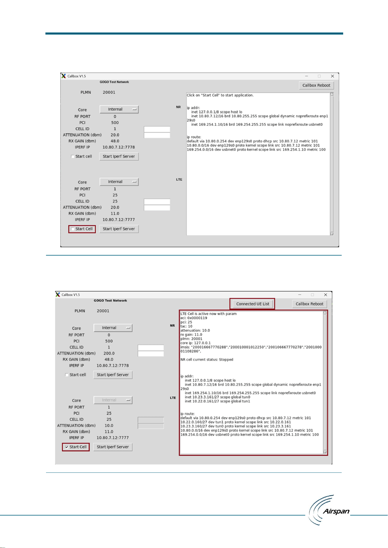
If cell start failed due to any issue ‘Start Cell’ checkbox tick will be automatically removed, all the editable
textbox cleared, and error displayed in result window
Figure 18: Cell starts failed due to invalid gain value
After successful Cell start with supplied configuration, all the config freeze till cell stopped.
Figure 19: All the editable config freeze till cell stop
ATG Callbox UI installation and Test manual
– user manual
© Copyright Airspan Networks Ltd., 2026 P/N: EVO084-SW-0008 Rev I, Aug 2026
17
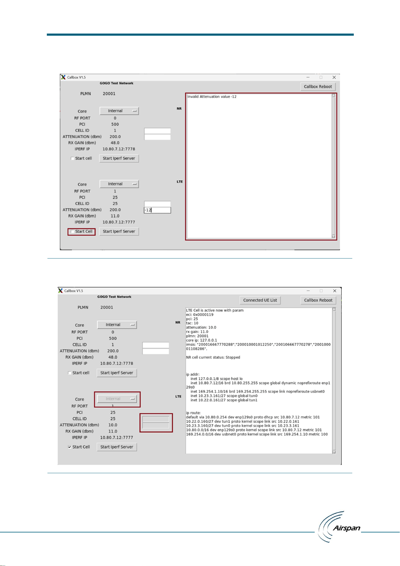
2. Start 4G/LTE Cell:
Now click on ‘Start Cell’ button to start 4G/LTE cell.
Figure 20: Start Cell button
If cell starts successfully with supplied configuration, then click on ‘Start Cell’ checkbox remains, ‘Connected UE
List’ button now becomes visible and supplied valid configuration settings displayed on result window.
Figure 21: Cell started with valid configuration
ATG Callbox UI installation and Test manual
– user manual
© Copyright Airspan Networks Ltd., 2026 P/N: EVO084-SW-0008 Rev I, Aug 2026
18
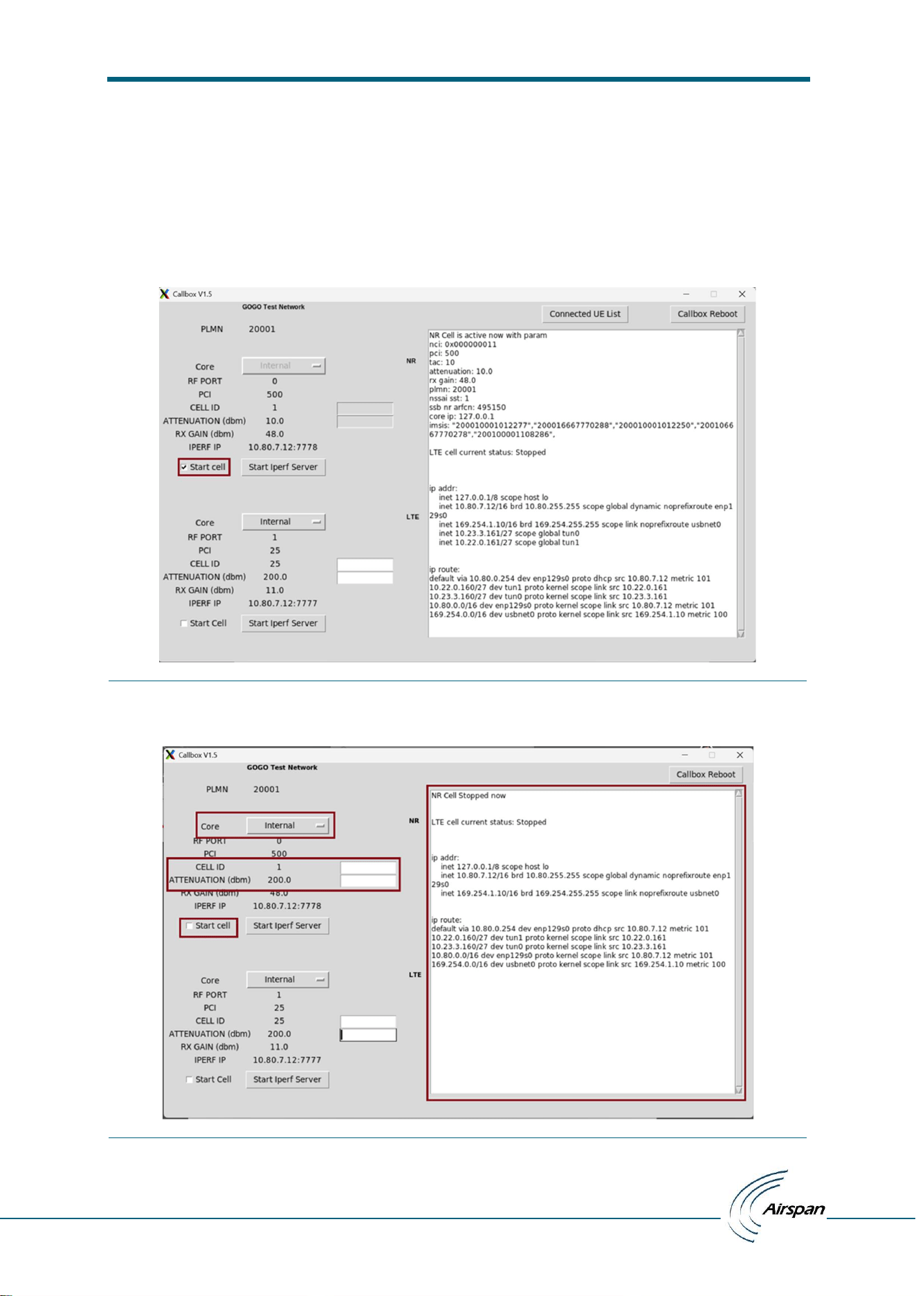
If cell start failed due to any issue ‘Start Cell’ checkbox tick will be automatically removed, all the editable
textbox cleared, and error displayed in result window
Figure 22: Cell starts failed due to invalid gain value
After successful Cell start with supplied configuration, all the config freeze till cell stopped.
Figure 23: All the editable config freeze till cell stop
ATG Callbox UI installation and Test manual
– user manual
© Copyright Airspan Networks Ltd., 2026 P/N: EVO084-SW-0008 Rev I, Aug 2026
19
3. Stop Cell:
Callbox start with default attenuation value 200 (attenuation valid range 10 to 200dB) but if user wants to
change the operational attenuation value with which cell should start every time, then that value needs to
update in textbox then click on ‘Start Cell’ button to apply. Now this new value will be updated as
CELL_ATTENUATION_4G for 4g/lte cell or CELL_ATTENUATION_5G for 5g/NR cell in final_ascb.conf.
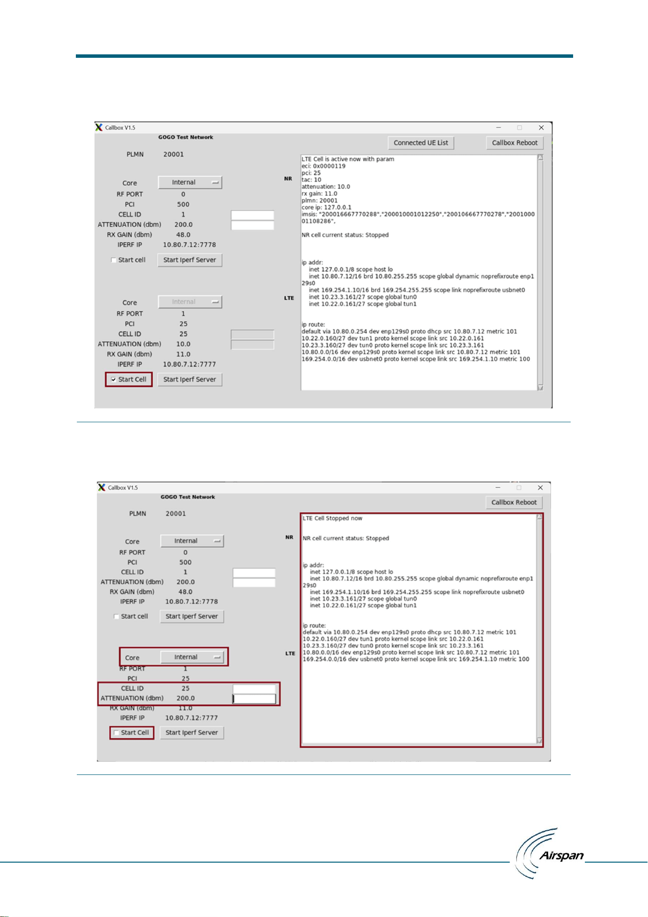
4. Stop 5G/NR Cell:
Now to stop the cell needs to click on same ‘Start Cell’ checkbox.
Figure 24: Cell start checkbox used to stop cell
After cell stop click on ‘Start Cell’ checkbox removed, Attenuation value updated as 200dB and result window
updated with Cell Stopped now notification while all the editable config unfreezes.
Figure 25: Cell stopped
ATG Callbox UI installation and Test manual
– user manual
© Copyright Airspan Networks Ltd., 2026 P/N: EVO084-SW-0008 Rev I, Aug 2026
20
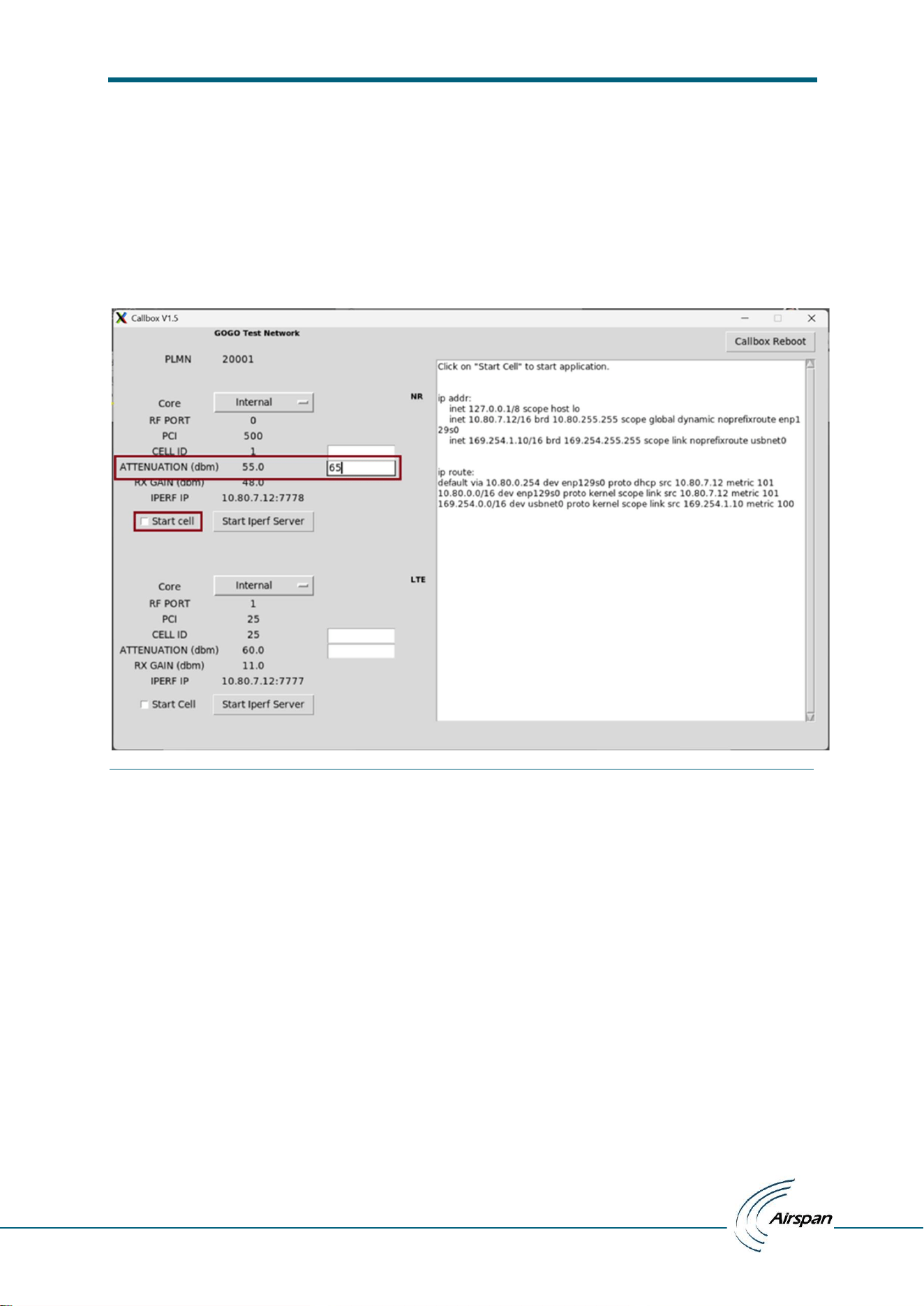
5. Stop 4G/LTE Cell:
Now to stop the cell needs to click on same ‘Start Cell’ checkbox.
Figure 26: Cell start checkbox used to stop cell
After cell stop click on ‘Start Cell’ checkbox removed, Attenuation value updated as 200dB and result window
updated with Cell Stopped now notification while all the editable config unfreezes.
Figure 27: Cell stopped
ATG Callbox UI installation and Test manual
– user manual
© Copyright Airspan Networks Ltd., 2026 P/N: EVO084-SW-0008 Rev I, Aug 2026
21
6. Cell Start / Stop and Attenuation relation:
To stop cell, attenuation value updated as 200dB and to start cell attenuation value changed to 10 or user
supplied operational attenuation. At 200dB cell won’t transmit so won’t be visible to UE. We are doing this
to enable/disable cell as service start/stop apply to second cell also and thus interfere with second cell
operations.
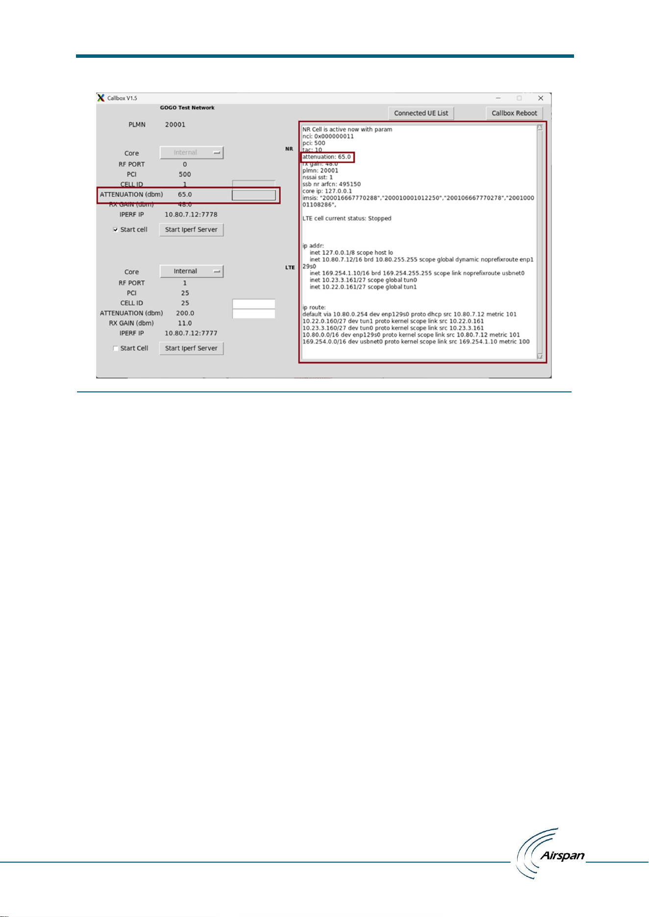
7. Attenuation / Operational attenuation updating:
To change operational attenuation; We can update any value between 10 to 200 dB (range can be changed
based on /root/enb/config/airspan/max_gain.cfg file which reflects hardware gain limits) and click on
‘Start Cell’
Figure 28: Update attenuation
ATG Callbox UI installation and Test manual
– user manual
© Copyright Airspan Networks Ltd., 2026 P/N: EVO084-SW-0008 Rev I, Aug 2026
22
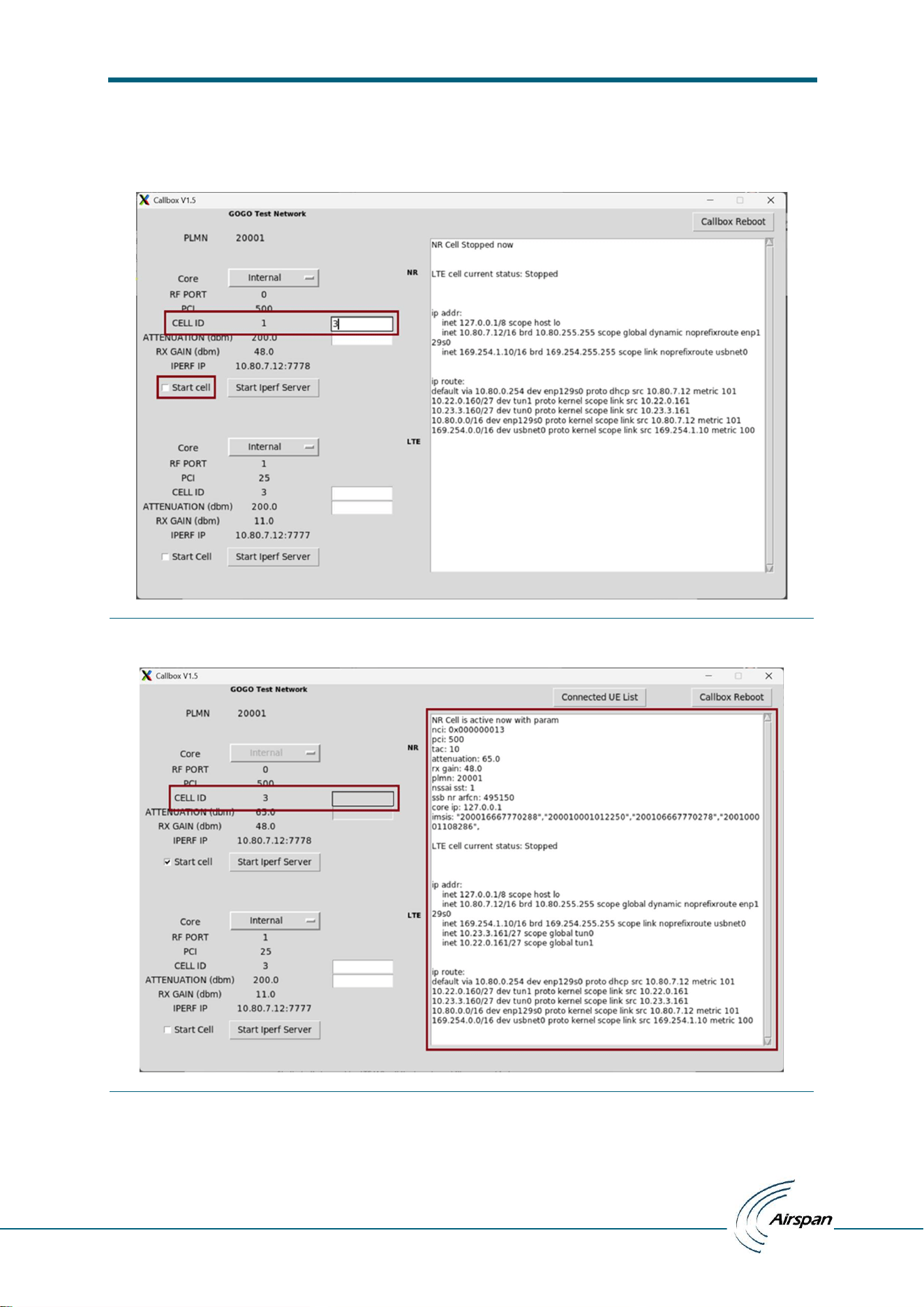
Figure 29: Cell started with updated operational attenuation
Now cell starts with this operational attenuation 65 dB for every reboot till final_ascb.conf file delete or again
change attenuation as above. In final_ascb.conf file attenuation entry added as below
CELL_ATTENUATION_5G: 65
Similarly, if changed for LTE/4G cell in final_ascb.conf file entry added as CELL_ATTENUATION_4G.
ATG Callbox UI installation and Test manual
– user manual
© Copyright Airspan Networks Ltd., 2026 P/N: EVO084-SW-0008 Rev I, Aug 2026
23
8. Cell Id updating:
To change cell id; We can update any value between 0 to 15 (4 bit length) for NR/5G cell while 0 to 255 (8 bit
length) for LTE/4G then click on ‘Start Cell’
Figure 30: Update cell id
Figure 31: Cell started with updated cell id
Now cell starts with this cell id 3 for every reboot till final_ascb.conf file delete or again change cell id as above.
In final_ascb.conf file cell id entry added as below
NR_CELL_ID: 3
Similarly, if changed for LTE/4G cell final_ascb.conf file entry added as LTE_CELL_ID.
ATG Callbox UI installation and Test manual
– user manual
© Copyright Airspan Networks Ltd., 2026 P/N: EVO084-SW-0008 Rev I, Aug 2026
24
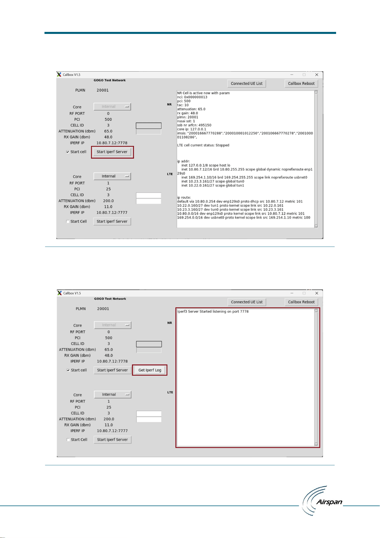
9. Start Iperf Server:
Click on ‘Start Iperf Server’ button to start iperf server on Callbox.
Figure 32: Start Iperf server
Start Iperf server triggers iperf3 session on Callbox.
If Iperf server started successfully then ‘Get Iperf Log’ button becomes visible to get the server result of last
iperf test and notification displayed on result window.
Figure 33: Iperf server started on Callbox
ATG Callbox UI installation and Test manual
– user manual
© Copyright Airspan Networks Ltd., 2026 P/N: EVO084-SW-0008 Rev I, Aug 2026
25
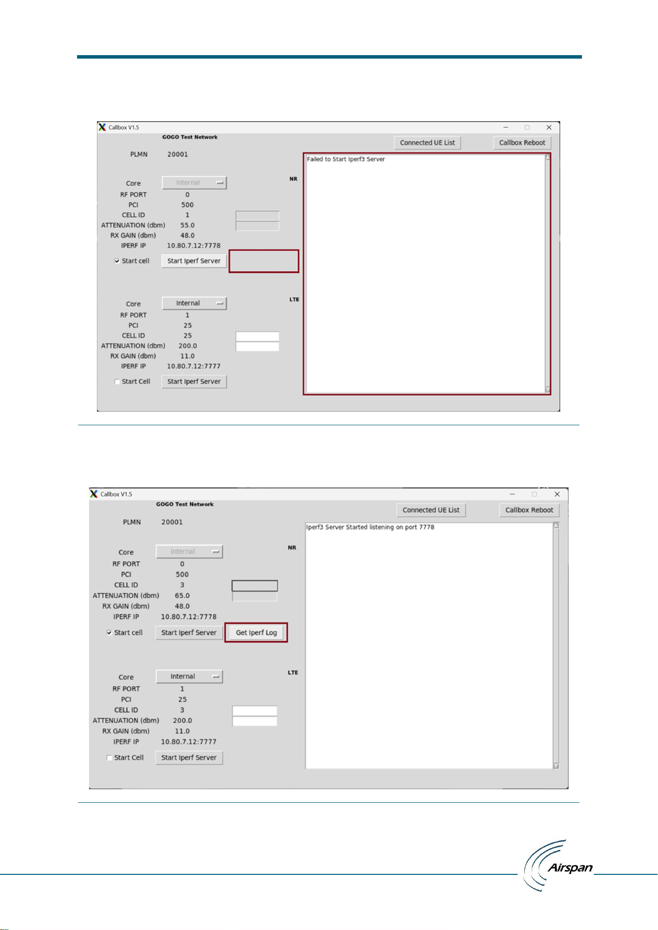
If Iperf server failed to start then ‘Get Iperf Log’ button won’t be visible, and notification will be displayed on
result window.
Figure 34: Failed to start iperf server on Callbox
10. Get Iperf Log:
‘Get Iperf Log’ if clicked on will fetch last iperf test result
Figure 35: Get Iperf Log button
ATG Callbox UI installation and Test manual
– user manual
© Copyright Airspan Networks Ltd., 2026 P/N: EVO084-SW-0008 Rev I, Aug 2026
26
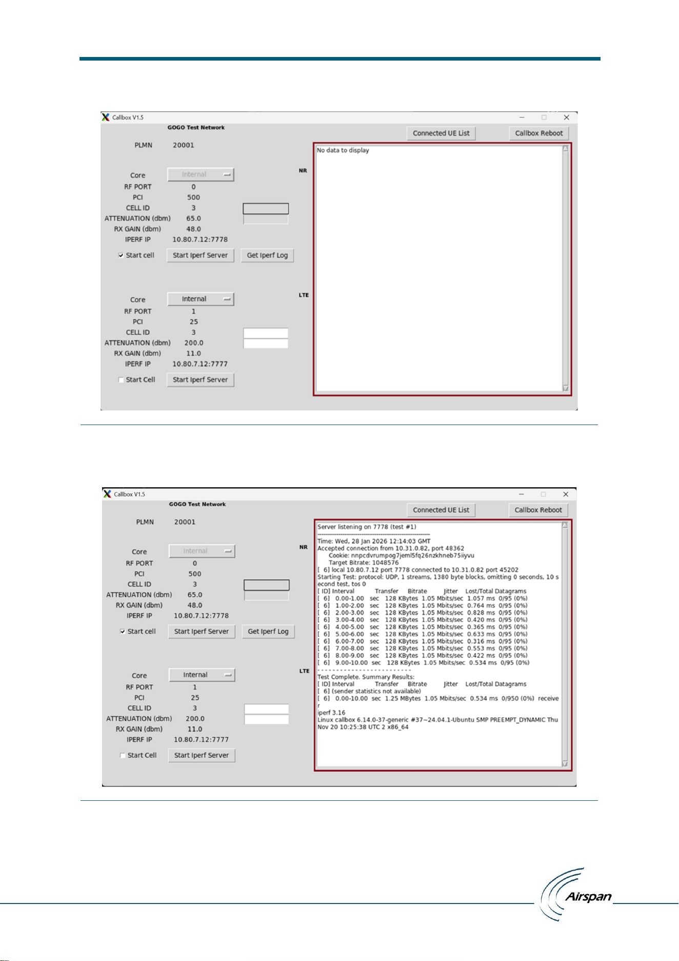
If iperf test not run yet, then ‘No data to display’ notification prints on result window
Figure 36: No data to display
Now run the iperf client and wait till test complete then click on ‘Get Iperf Log’ button, server test result will be
displayed on result window
Figure 37: Get Iperf Log fetches last iperf test result
ATG Callbox UI installation and Test manual
– user manual
© Copyright Airspan Networks Ltd., 2026 P/N: EVO084-SW-0008 Rev I, Aug 2026
27
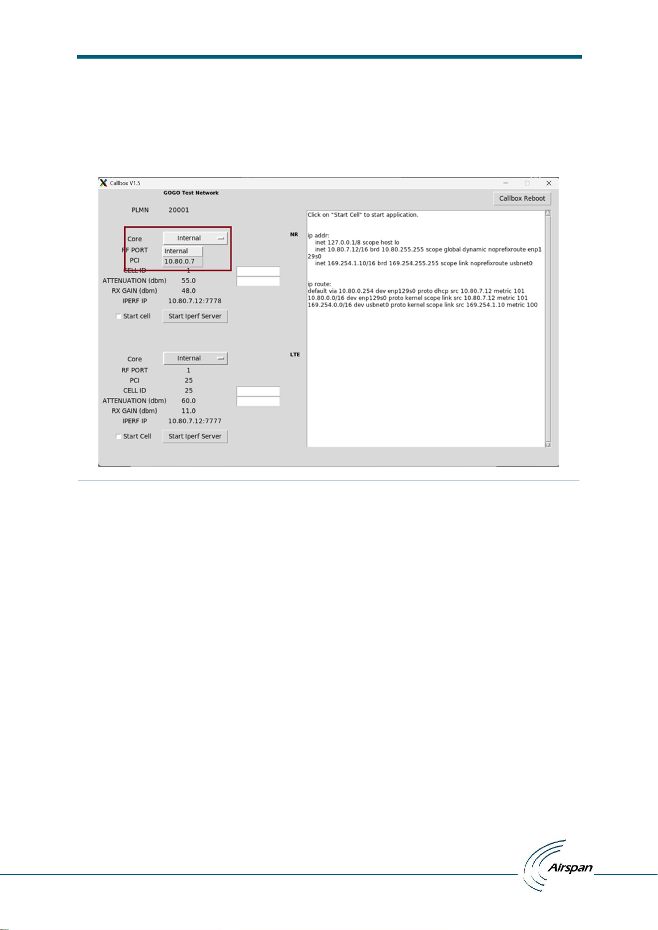
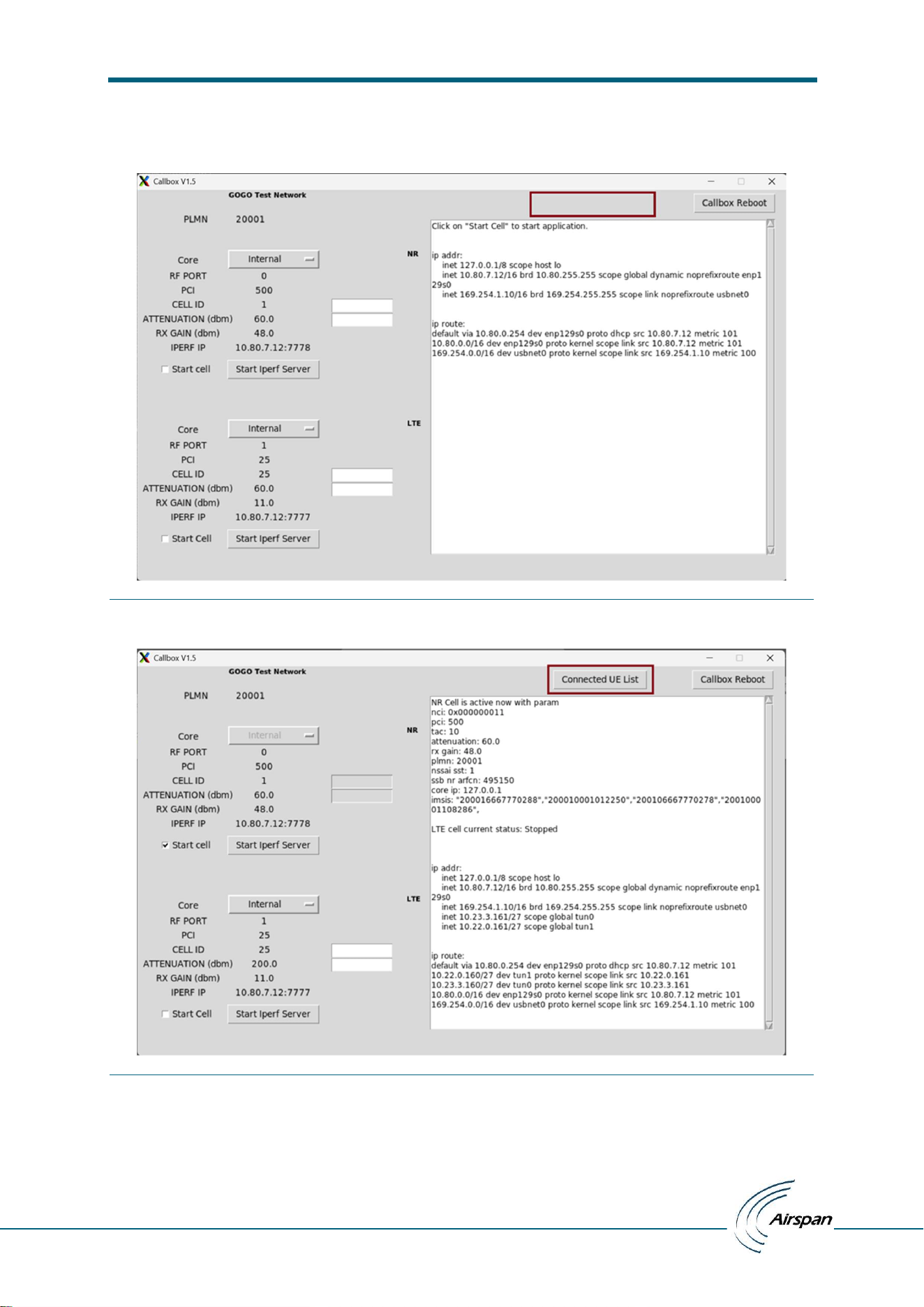
11. Core Dropdown:
Core dropdown can be used for Internal or External (external core ip will be listed here) core selection.
Dropdown menu will be available based on value of mme ip ‘MME_IP’ param in ascb.conf file. If ‘MME_IP’
param value passed as Callbox ip or loopback ip (127.0.0.1) then no dropdown menu appears while fixed
‘Internal’ value displayed for core while for any other ip value core will be displayed with dropdown and
with ‘Internal’ and ‘Exernal ip address” as below.
Figure 38: Core selection
By default, ‘Internal’ core will be selected in selection dropdown, user has to select external core
manually if he wants to.
ATG Callbox UI installation and Test manual
– user manual
© Copyright Airspan Networks Ltd., 2026 P/N: EVO084-SW-0008 Rev I, Aug 2026
28
12. Connected UE List:
‘Connected UE List’ button won’t appears initially, or cell start fails and appears only if cell started successfully
Figure 39: Connected UE List button disappears if cell not started
Figure 40: Connected UE List button appears as cell started successfully

ATG Callbox UI installation and Test manual
– user manual
© Copyright Airspan Networks Ltd., 2026 P/N: EVO084-SW-0008 Rev I, Aug 2026
29
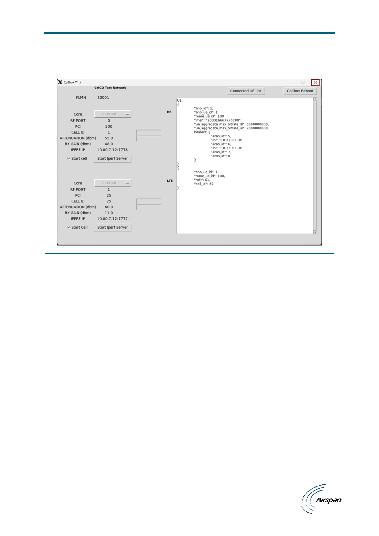
User has to click on ‘Connected UE List’ button to get connected ue data
Figure 41:Connected UE List data
Connected UE List data contains two blocks for Internal core case, first block for MME ue data and second
block for eNB ue data while for external core case only eNB ue data block present
Figure 42: MME UE data block and eNB UE data block
ATG Callbox UI installation and Test manual
– user manual
© Copyright Airspan Networks Ltd., 2026 P/N: EVO084-SW-0008 Rev I, Aug 2026
30
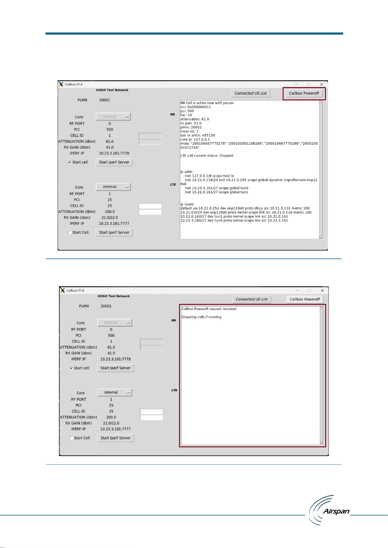
13. Close the application:
To close application user need to click on ‘X’ which will close the application window, all the iperf instances
running and stops lte service on Callbox.
Figure 43: Close the application
On startup and on exit, application will kill all the iperf3 and stop lte service running on callbox.
ATG Callbox UI installation and Test manual
– user manual
© Copyright Airspan Networks Ltd., 2026 P/N: EVO084-SW-0008 Rev I, Aug 2026
31
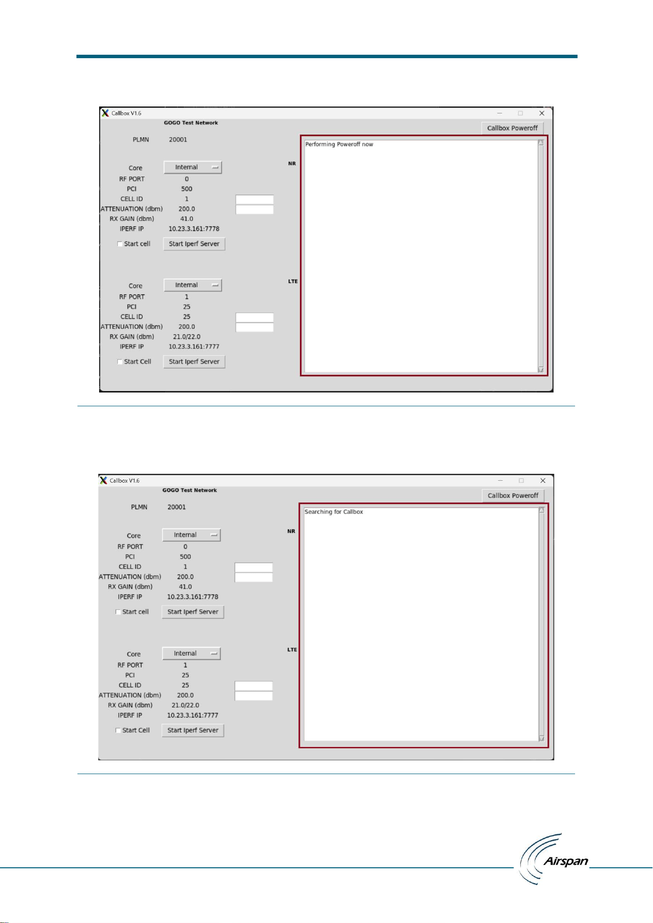
14. Poweroff the Callbox:
To poweroff callbox user need to click on ‘Callbox Poweroff’ button which will poweroff callbox unit (it execute
poweroff command in linux shell).
Figure 44: Poweroff the Callbox
Poweroff request received now stopping cells if running also iperf servers if running.
Figure 45: Poweroff the Callbox request received
ATG Callbox UI installation and Test manual
– user manual
© Copyright Airspan Networks Ltd., 2026 P/N: EVO084-SW-0008 Rev I, Aug 2026
32
Executing poweroff command in Callbox shell
Figure 46: Callbox performing poweroff command
Application searching for Callbox to confirm poweroff (callbox gets offline/disconnected, needs manual power
on)
Figure 47: Searching for Callbox
ATG Callbox UI installation and Test manual
– user manual
© Copyright Airspan Networks Ltd., 2026 P/N: EVO084-SW-0008 Rev I, Aug 2026
33
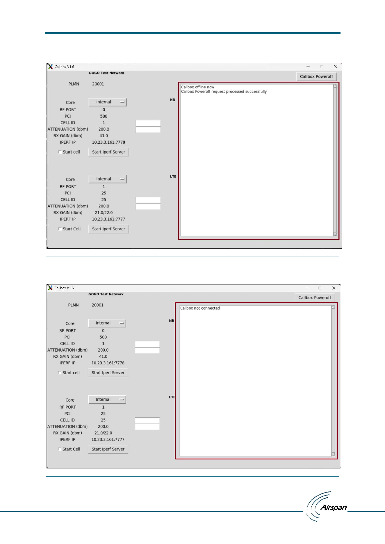
Callbox is offline now and application is in disconnected state
Figure 48: Callbox Poweroff request processed successfully; now Callbox offlin.
For any action/button press Callbox recheck connectivity
Figure 49: Callbox still offline
ATG Callbox UI installation and Test manual
– user manual
© Copyright Airspan Networks Ltd., 2026 P/N: EVO084-SW-0008 Rev I, Aug 2026
34
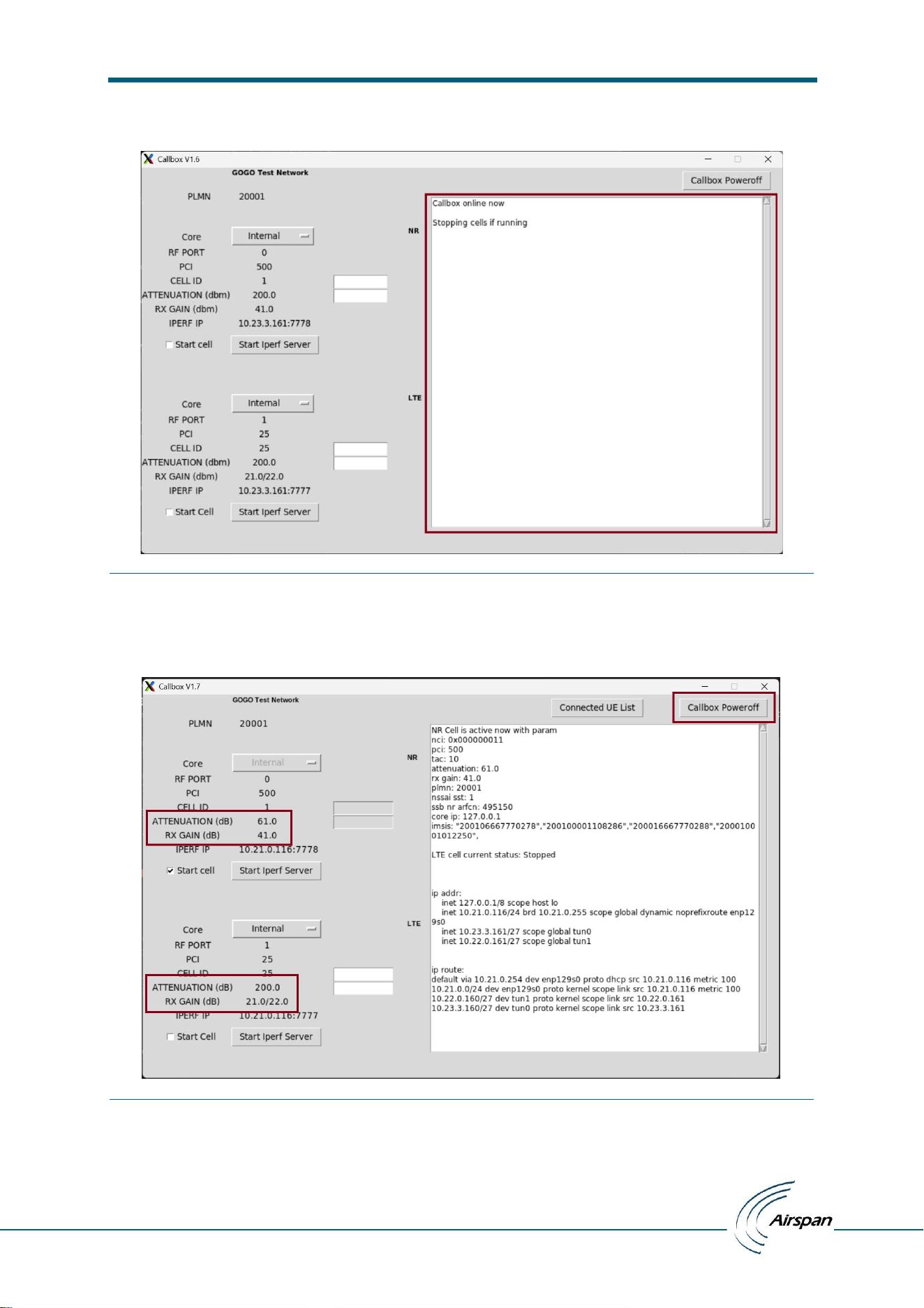
Callbox is online now and application starts performing intended actions
Figure 50: Callbox online now
Latest UI update has “ATTENUATION” & “RX GAIN” unit corrected to dB in place of dbm and Callbox Reboot
Button converted to Callbox Poweroff.
Figure 51: Minor UI Corrections
ATG Callbox UI installation and Test manual
– user manual
© Copyright Airspan Networks Ltd., 2026 P/N: EVO084-SW-0008 Rev I, Aug 2026
35
15. Keep Online Callbox after application close:
For every time we close UI application Callbox service stops so cell/cells down; To prevent this and keep
Callbox service on user need to check ‘Keep Online’ checkbox.
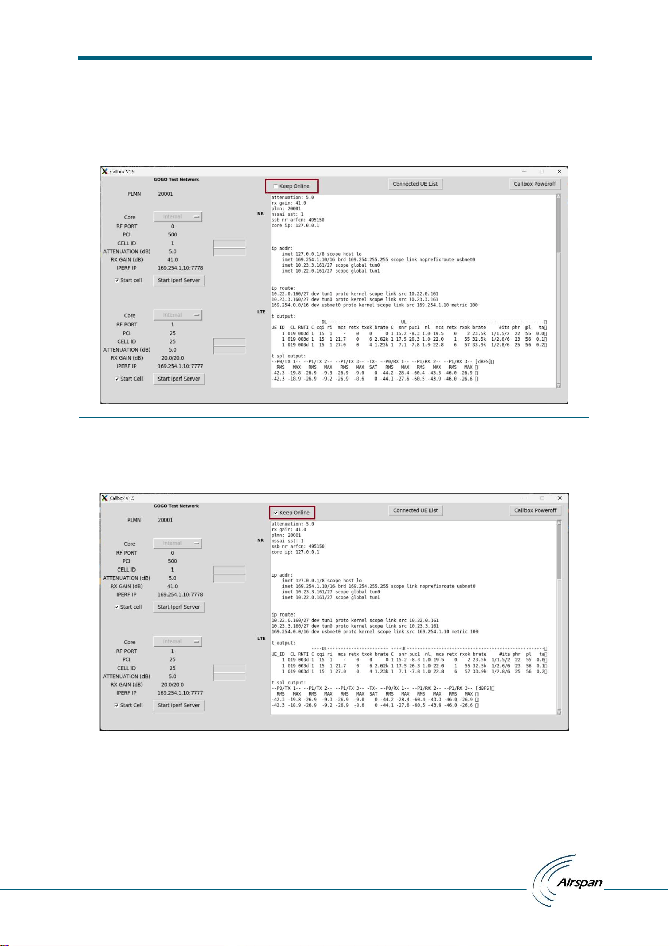
Checkbox unchecked: Default behavior; for UI application close Callbox service stops thus cell/cells down
Figure 52: Keep Online unchecked
Checkbox checked: For UI application close Callbox remains online and current state maintained for next
application start.
Figure 53: Keep Online checked
ATG Callbox UI installation and Test manual
– user manual
© Copyright Airspan Networks Ltd., 2026 P/N: EVO084-SW-0008 Rev I, Aug 2026
36
16. t & t spl screen command output:
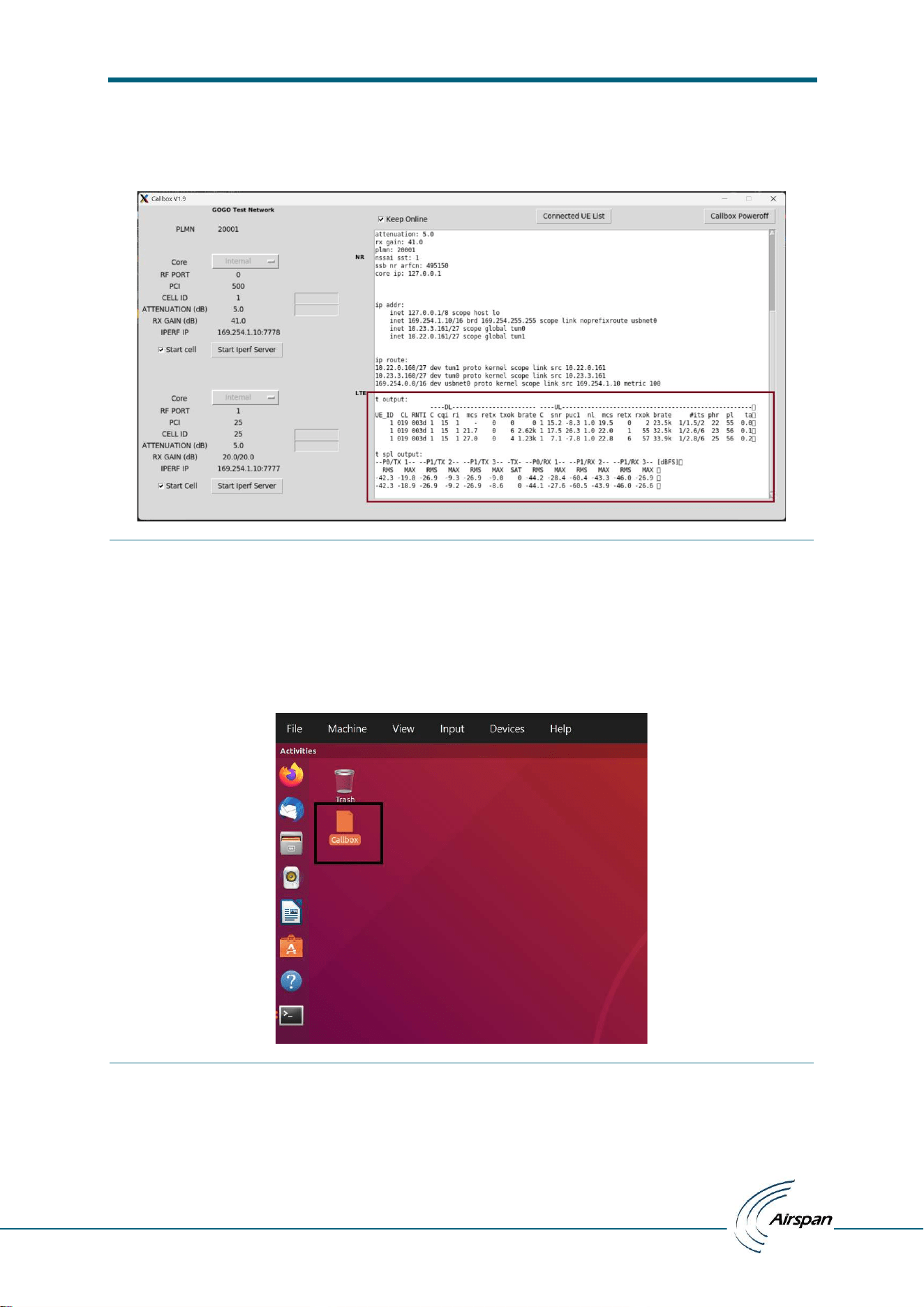
Whenever LTE/NR Start Cell or Connected UE List button pressed t output and t spl output printed at bottom
of result window.
Figure 54: t & t spl output
17. Desktop Shortcut:
Install.sh create desktop shortcut to launch UI application.
Figure 55: Desktop Shortcut
On startup and on exit, application will kill all the iperf3 and stop lte service running on callbox.

ATG Callbox UI installation and Test manual
– user manual
© Copyright Airspan Networks Ltd., 2026 P/N: EVO084-SW-0008 Rev I, Aug 2026
37
5 Regulatory
5.1 Human Exposure to Radio Frequencies
The Safety Distance for the ATG Call Box is 55mm. Users should be no closer than 55mm
from the antenna on the equipment.
5.2 FCC Statements
This device complies with Part 15 of the FCC rules. Operation is subject to the following two
conditions:
1. This device must accept any interference, and
2. This device must accept any interference received including interference that may cause
undesired operation
Changes or modifications not expressly approved by Airspan could void the user’s authority to
operate the equipment.
Note: This equipment has been tested and found to comply with the limits for a Class A digital
device, pursuant to part 15 of the FCC Rules. These limits are designed to provide reasonable
protection against harmful interference when the equipment is operated in a commercial
environment. This equipment generates, uses, and can radiate radio frequency energy and, if not
installed and used in accordance with the instruction manual, may cause harmful interference to
radio communications. Operation of this equipment in a residential area is likely to cause harmful
interference in which case the user will be required to correct the interference at his own expense.
This equipment must be professionally installed.
Only the supplied antennae are to be used with the equipment.