1
2 3
4
5
6
7
8
9
10
11
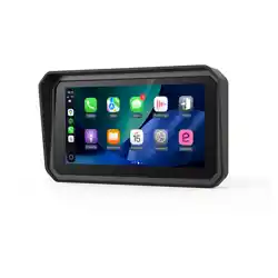
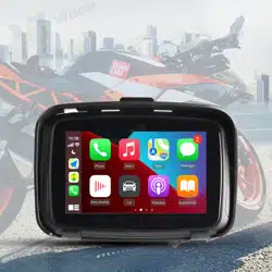
This product is engineered for motorcycle use, seamlessly blending four advanced technologies to enhance both riding experience
and safety:
1. Dual Ultra HD Cameras
Front and rear 1440P cameras support day-and-night recording with loop storage for incident footage. Starlight night vision main-
tains clarity in low-light conditions, ensuring every journey is captured clearly.
2. Smart Full-Scene Connectivity
Supports CarPlay, and Android Auto for seamless smartphone integration. Voice control enables hands-free navigation, music
playback, and calling. Real-time traffic updates help maintain focus on the road.
3. Active Safety Features
BSD: Millimeter-wave radar warns of vehicles in blind zones up to 2 seconds in advance, reducing collision risks.
TPMS: Continuously monitors tire pressure and temperature, alerting riders to anomalies to help prevent accidents.
4. Rugged, All-Weather Design
Constructed with a durable metal frame and IP67 waterproof rating, it resists heavy rain, dust, and vibration-ideal for long-distance
and extreme-weather riding.
1. The device has built-in storage and supports Micro SD cards.
2. It is recommended to use a high-speed Micro SD card (Class 10 or above), with
a minimum capacity of 32GB and a maximum support of 256GB.
3. After installation, please format the Micro SD card for the first use — go to
Device Settings > System Settings > About Device > Format.
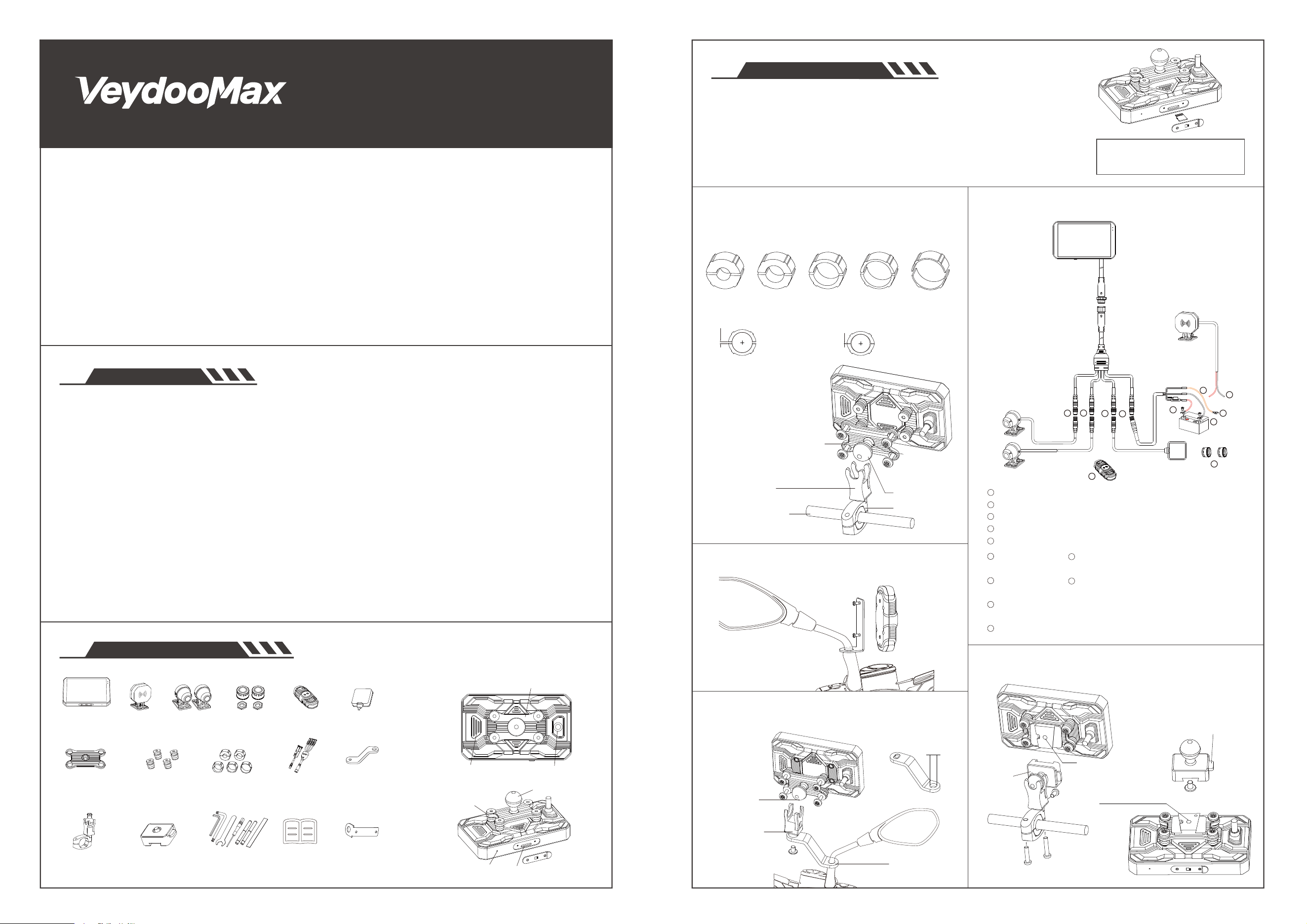
Select the appropriate size adapter ring based on the
handlebar diameter.
Rear cable connects to the rear camera.
Front cable connects to the front camera.
GPS cable connects to the GPS module.
Power cable connects to the main unit power line.
Power B+ cable connects to the battery positive terminal.
Power GND cable + radar negative cable connects to the battery
negative terminal.
Power ACC cable + radar positive cable connects to the battery
ACC line.
Front/Rear tire pressure sensors are installed at the respective tire
valve positions.
Remote connects to the main unit via Bluetooth.
Main Unit X1 BSD X1 Camera X2 TPMS X2 GPS X1BT Remote X1
Main Unit
Power Cable
Fixed Base X1
Z-Type
Bracket
L-Type
Bracket
Reducer Ring
Installation
Tool
User Manual X1
Quick-release
Bracket
Vibration
Damping
Bracket
Vibration
Damping
Silicone
01
03
Installation Instructions
02
Main Unit & Accessories
[Ball Head Bracket Installation Instructions]
[Quick Release Bracket Installation/Removal]
[Component Details]
[Micro SD Card Installation]
[Z-Bracket Installation Instructions]
[L-Bracket Installation for Bluetooth Remote]
[Wiring Instructions]
Speaker Output Port
Power Cable Port
Floating Vibration Damping
22mm Ball Head
Micro SD Card Slot
Microphone
Vibration Damping
Silicone
Ball Head
Fixed Base
Reducer Ring
12-28mm Cylinder
Floating Vibration Damping
Quick
Release
Bracket
16mm12mm 22mm 24.5mm 28mm
1
2
3
4
5
6
7
10
11
9
8
AI Riding System
V5 User Manual
1. Please read these instructions carefully.
2. This set is exclusively for motorcycle with negative grounding and 12V power supply.
3. Please turn off the power of motorcycle before finishing installation.
4. After choosing the best position,fixed the DVR parts on.
5. Do not use high-pressure water gun to flush the machine!
6. This product max support for 256GB Micro SD card, in order to make sure video recording normally,
please must be use high speed Class 10 Micro SD card(Reading speed of 100Mb/s, writing speed of 60Mb/s).
7. When connecting cameras,please check the right camera with right mark.F (short wire) connect front camera, B(long wire)
connect rear camera.
8. Cameras are fully sealed waterproof, but still need to avoid using Cleaning Naphtha, alcohol, and Solvents such as tar
detergent come into contact with the lens to prevent damage. the waterproof layer.
Tips
Product Overview
Micro SD card backs up collision
videos. Format regularly for best
performance.
X1
X1 X4 X5 X1 X1
X1 X7
Note: For storage speed and security, please clean the Micro SD car regularly.
Press the quick-release
button, The entire unit
can be removed.
Approx. 2mm gap
when installed.
Add an anti-slip pad
if no gap.
2.0mm
0mm
Ball Head
Fixed Base
Z-Bracket
10.4mm
M6x12(Allen)
M2.5x5(Allen)
B+
GND
ACC
Power
Power
Front
Rear
GPS
GPS
Front
Rear
M4x18(Torx)
M6x12(Allen)
Apply some threadlocker
to the screw.
M6x25(Torx)
M6x30(Torx)
M6x12(Torx)
M6x8(Allen)
M6x12(Allen)
Apply some threadlocker to
the quick-release screw.
Apply some threadlocker
to the screw.
Battery life: 2 years
Dimensions: 21x15.6mm
Battery replacement: CR1632
Pressure monitoring range: 0 to 87psi (0 to 600kPa)
Temperature monitoring range: -40℃ to 85℃
Normal
Abnormal
Low battery
Lost signal
Air leakage
1. Pairing Mode: Press and hold the leftmost and rightmost buttons simultaneously to enter pairing mode. The LED will flash red and blue
alternately 5 times.
2. Battery Status: Blue light if battery > 2.85V; Red light if battery < 2.85V.
A dedicated tool is available
for battery replacement
Anti-theft cap
04
Bluetooth Remote Instructions
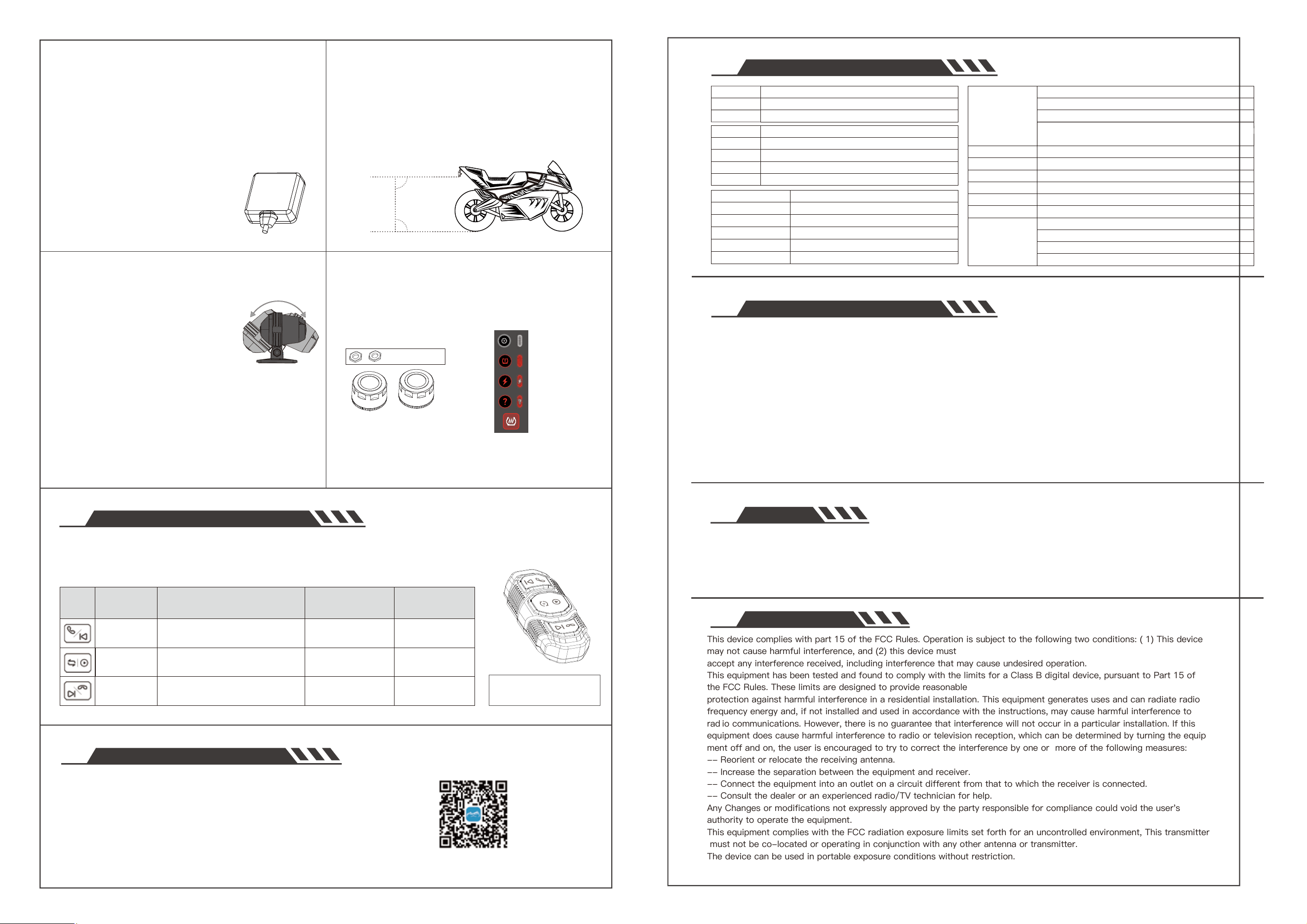
Peel off the 3M adhesive and mount the GPS inside the
vehicle shell.
1. Do not install under carbon fiber material.
2. Avoid metal obstructions.
3. Keep away from cameras, camera cables, and the main
unit as much as possible.
4. If GPS signal is not received, try repositioning it.
5. Note during installation: This Side Up
— keep the marked side facing up.
[GPS Installation Notes]
Remove the 3M adhesive and stick the
front and rear cameras to the front and
rear of the vehicle respectively.
1. Loosen the screws to rotate the
camera 180° forward and backward.
2. Adjust the camera arrow indicator to
face straight upward.
3. If installed upside down, rotate the
camera 180° and adjust the angle
accordingly.
[Camera Installation Notes]
Remove the 3M adhesive and install the radar on the rear of
the vehicle. The installation height should be between
60–90cm from the ground, and the radar should be installed
vertically at 90° to the ground. If installed in reverse, loosen
the screws and rotate the radar 180° forward and backward
to adjust.
[Radar Installation Notes]
After the device is powered on, install the tire pressure sensors.
Once paired, they enable real-time pressure monitoring and alert
you when abnormal conditions occur.
[Tire Pressure Sensor Installation Notes]
05
WiFi APP Software Download
Download the MotoNavi APP for real-time video viewing, playback
of videos/photos, downloading files, and setting options for
VeydooMax V5.
WiFi Name: VeydooMax_xxxxxx
Password: 12345678
【Note】Before using the 3M adhesive, clean the mounting
surface thoroughly. Press firmly for more than 10 seconds
when applying, and let it sit undisturbed for 30 minutes to
ensure optimal adhesion.
60-90cm
90°
90°
Model
Dimensions
Display
VeydooMax V5
137.6*83.5*25.4mm
5-inch, 1024×600, Brightness 1000 nit
CPU
Storage
Bluetooth
WiFi
GPS
Dual-core A55
128/256GB eMMC, up to 256GB Micro SD
5.4
5GHz for PhoneLink
Supports BDS/GPS/GLONASS/Galileo/QZSS
OS
PhoneLink
Wireless Remote
AI Anti-Shake
Loop Recording
Software Upgrade
Linux
CarPlay, Android Auto, MotoNavi, WiFi Video
Supported
Supported
Supported
SD-Card and OTA supported
Sensors
Tire Pressure
BSD Radar
Speaker
Battery
Quick Release
Sensor:Sony IMX675
Lens:F1.80±5%, 2G+4P+IR, FOV D:139° H:107° V:70°
Resolution: 2K, 2560*1440@30fps
Cable length:Front camera 1200mm+300mm
Rear camera 2700mm+300mm
Light sensor, 3-axis G-sensor
Supported
24GHz BSD supported
Supported,8Ω 1W
Super Capacitor
Supported
Operating Voltage:9~32V
Operating Temperature: -20°~70°
Storage Temperature:-25°~80°
Waterproof Rating:IP67
06
Product Features & Specifications
Camera
Operating
Environment
1. Loop Recording Fails
Format Card: Format new or error-prone cards via device settings.
Check Feeds: Ensure cameras display correctly; signal errors block recording.
Replace Card: If formatting fails, use a new Micro SD.
2. No Image Display
Secure Links: Check for loose plugs or damaged cables.
Swap Ports: Cross-test front/rear connections to isolate the fault.
3. Lag or System Lag
Use Class 10: Only use high-speed brand cards. Low-quality cards cause lag, artifacts, or crashes.
4. Settings Not Saving
Power Loss: Ensure the device doesn't lose power abruptly after adjusting settings.
To ensure video integrity, the device must remain in normal recording mode. Data loss or corruption may occur if:
Sudden Interruption: Removing the SD card or losing power during recording will damage the current file.
Physical Impact: Severe crashes or impacts that loosen the memory card can result in file loss.
Disclaimer: Recordings are for reference only. The company is not liable for data loss caused by abnormal operating conditions.
07
Frequently Asked Questions (FAQ)
08
Disclaimer
09
FCC WARNING
Please scan to
download and install
Button Function Short Press Long Press (2s) Double Press
Function triggered immediately
after the second press
Answer Call
Previous Track
Video Lock
Event recording
Take a Photo
During Music Playback:
Pause/Play Music
Lock /Unlock Screen
/
Turn Screen On / Off
End Call
Next Track
Take Photo
Switch
Pause/Play Music
Incoming Call:Reject call
During Call:End call
During Music Playback:Next track
Dashboard > PhoneLink > DVR Rear View >
DVR Front View > DVR Rear and Front(small)
> DVR Front amd Rear(small) > Dashboard
Incoming Call:Answer Call
During Music Playback:Previous Track
When using Motonavi, the remote
cannot answer calls. Please use
your headset or phone instead.
This device complies with part 15 of the FCC Rules. Operation is subject to the following two conditions: ( 1) This device
may not cause harmful interference, and (2) this device must
accept any interference received, including interference that may cause undesired operation.
This equipment has been tested and found to comply with the limits for a Class B digital device, pursuant to Part 15 of
the FCC Rules. These limits are designed to provide reasonable
protection against harmful interference in a residential installation. This equipment generates uses and can radiate radio
frequency energy and, if not installed and used in accordance with the instructions, may cause harmful interference to
rad io communications. However, there is no guarantee that interference will not occur in a particular installation. If this
equipment does cause harmful interference to radio or television reception, which can be determined by turning the equip
ment off and on, the user is encouraged to try to correct the interference by one or more of the following measures:
-- Reorient or relocate the receiving antenna.
-- Increase the separation between the equipment and receiver.
-- Connect the equipment into an outlet on a circuit different from that to which the receiver is connected.
-- Consult the dealer or an experienced radio/TV technician for help.
Any Changes or modifications not expressly approved by the party responsible for compliance could void the user's
authority to operate the equipment.
This equipment complies with the FCC radiation exposure limits set forth for an uncontrolled environment, This transmitter
must not be co-located or operating in conjunction with any other antenna or transmitter.
The device can be used in portable exposure conditions without restriction.