Garvee 7EOBM Airless Spray Station 1010W - Instruction Manual
Product Components
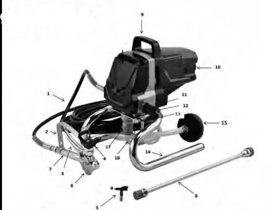
- Spray Hose
- Trigger Guard
- Trigger
- Nozzle Guard
- Spray Tip
- Spray Gun
- Spray Gun Handle
- Lance
- Carry Handle
- ON/OFF Switch
- Prime/Spray Switch
- Return Hose Inlet Port
- Return Hose
- Stand
- Suction Hose Filter
- Suction Hose
- Suction Hose Inlet Port
- Spray Hose Outlet Port
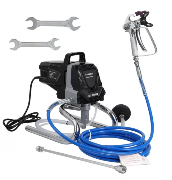
Contents of Box
1 x Airless Spray Station 1010W
1 x Spray Gun
1 x Spray Tip
1 x Spray Hose 7.5m
1 x Lance
2 x Hex Wrench
1 x Instruction Manual
Controls and Functions
| Components |
Description |
| ON/OFF Switch (10) |
The ON/OFF Switch (10) turns the power to the sprayer ON (“I”) and OFF (“O”). |
| Prime/Spray Switch (11) |
The Prime/Spray Switch (11) directs fluid to the Spray Hose (1) when set to SPRAY or to the Return Hose (13) when set to PRIME.
The Prime/Spray Knob is also used to relieve pressure built up in the Spray Hose (refer to Pressure Relief Procedure on page 18). |
| Pressure Gauge (8) |
Optional accessory that identifies the amount of force the pump uses to push the fluid through the Spray Gun (6). |
| Suction Hose (16) |
Fluid is drawn through the Suction Hose (16) into the pump. |
| Return Hose (13) |
Fluid is sent back through the Return Hose (13) to the original container when Prime/Spray Switch (10) is in PRIME position. |
| Suction Hose Filter (15) |
Strains the spray material to prevent the system from being clogged. |
| Spray Gun (6) |
Controls the delivery of the fluid being pumped. |
| Spray Hose (1) |
Connects the Spray Gun (6) to the pump. |
| Lance (19) |
Optional accessory that can be attached to the end of the Spray Gun (6) to spray hard to reach areas.
|
Description of Symbols
The rating plate on your tool and in this user manual may show the following symbols. These represent important information about the product or instructions on its use.
 - WARNING - To reduce the risk of injury, user must read instruction manual.
 - Denotes risk of personal injury, loss of life or damage to the tool in case of non-observance of the instructions in this manual.
 - Wear hearing protection. Wear eye protection. Wear breathing protection.
 - Conforms to safety and EMC standards.
 - Indicates electrical shock hazard.
 - Class II tool.

Material / Paint Selection
Do not use textured wall paints or coatings as this will block the spray gun tip and damage internal components of the Airless Spray Station.
Although a large number of paints and materials can be sprayed, some cannot. Please check the manufacturers' recommendations before purchasing paint.
MATERIALS WHICH CAN BE USED:
Recommended for spraying the following materials:
- Water-based paints
- Wood preservatives
- Oil-based paints
- Primers
- Enamel paint
- Wash primer
- Varnish
- Oil
- Stains
MATERIALS WHICH CANNOT BE USED:
The Airless Spray Station CANNOT be used for the following materials:
- Paints and lacquers containing heavily abrasive components such as:
- Exterior textured wall paints
- Glazes
- Lyes
- Acids
- Dispersion paints
- Caustic and Alkaline substances
- Textured coatings
- Emulsion paints,
- Silicate paints.
- Flammable materials.
- Asphalt sealer.
- Block filler.
- Pesticides and liquid fertilisers.
The use of these materials will cause premature wear and block the spray tip and will void warranty. To obtain the best results from your Airless Spray Station, PLEASE READ THE INSTRUCTION MANUAL CAREFULLY BEFORE USE.
Assembly
WARNING! Ensure the machine is disconnected from the power supply before performing any of the following operations.
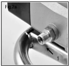
Spray Hose & Spray Gun Connection
- Thread the Spray Hose (1) and tighten with supplied wrench (Fig.2 a). Do not overtighten.
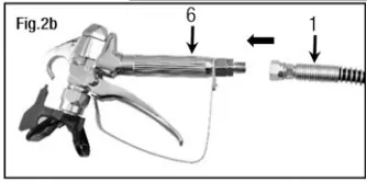
- Thread the other end of the Spray Hose (1) to the Spray Gun (6) and tighten with the supplied wrench (Fig.2b). Do not overtighten.
Connecting Lance to Spray Gun
The Lance (19) is an optional accessory. The Spray Gun (6) can be used with or without the Lance (19) accessory. The Lance (19) can be used to spray hard to reach areas.
- Remove the Nozzle Guard (4) and Spray Tip (5) from the Spray Gun (6) (Fig.3a).
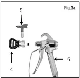
- Thread the Lance (19) onto the end tip of the Spray Gun (6) and tighten with supplied wrench (Fig.3a). Do not overtighten (Fig.3b).
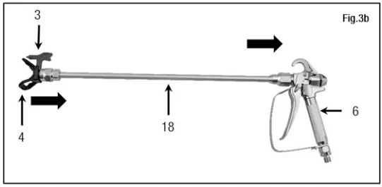
- Thread the Nozzle Guard (4) with the Spray Tip (5) onto the Lance (19) and tighten with the supplied wrench. Do not overtighten (Fig.3b).
Pre-Operation
WARNING! Ensure the machine is disconnected from the power supply before performing any of the following operations.
This section contains instructions that will be repeated throughout this manual. Read and understand this section before using the equipment.
Locking the Spray Gun Trigger
The spray gun Trigger (3) should be locked prior to preparing the spray station to ensure the Trigger (3) is not accidentally pressed.
Lock the spray gun Trigger (3) whenever instructed.
- To LOCK the Trigger (3), rotate the Trigger Locking Switch backwards towards the rear end of the spray gun (6) until it stops (Fig.4a).
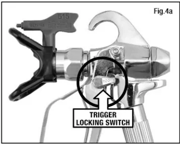
- To UNLOCK the Trigger (3), rotate the Trigger Locking Switch forward towards the Trigger Guard (2) until it stops (Fig.4b).

Pressure Relief Procedure
Always follow the Pressure Relief Procedure when shutting the machine off for any purpose. This procedure is used to relieve pressure from the Spray Hose (1). Failure to do so may result in serious injury.
Never aim the Spray Gun (6) towards at any part of your body, other people or animals.
Perform the Pressure Relief Procedure whenever instructed in this manual.
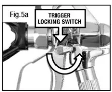
- Lock the spray gun Trigger (3) by rotating the Trigger Locking Switch towards the rear end of the Spray Gun (6) (Fig.5a).
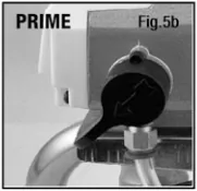
- Turn the Prime/Spray Switch (11) to the "PRIME" position by turning the Prime/Spray Switch (11) upwards (Fig.5b).
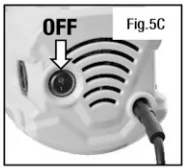
- Turn OFF the machine by pressing "O" on the On/Off Switch (10) (Fig.5c).
- Unlock the spray gun Trigger (3) by rotating the Trigger Locking Switch towards the Trigger Guard (2) until it stops (Fig.5d).
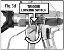
Then briefly pull the spray gun Trigger (3) into the side of a waste bucket to fully relieve pressure from the system.
- Lock the spray gun Trigger (3) (Fig.5a).
Priming the Unit
- Separate the Suction Hose (16) from the Return Hose (13), then:
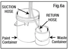
- Place the Suction Hose (16) inside a full container of paint (Fig.6a).
- Place the Return Hose (13) into a waste container (Fig.6a).
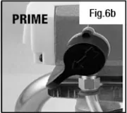
- Set the Prime/Spray Switch (11) to "PRIME" position (Fig.6b).
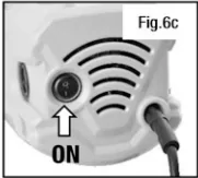
- Turn ON the machine by pressing "I" on the On/Off Switch (13) (Fig.6c).
- Allow pump to run for approx. 60 seconds until you see a steady stream of paint coming out of the Return Hose and into the waste container.
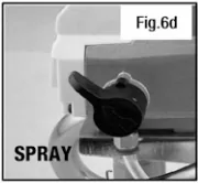
- Set the Prime/Spray Switch (11) to "SPRAY" position (Fig.6d).
- Wait for the Airless Spray Station to cut out after a few moments. If the Airless Spray Station does not shut off automatically, repeat steps 2 to 5.
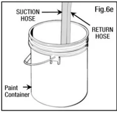
- Place the Return Hose (13) back into the container of paint and clip the Return Hose (13) and Suction Hose (16) together (Fig.6e).
Recommendation: It is good practice to perform the steps on this page using water to familiarize yourself with the function of the unit as well as to ensure the unit is set up properly.
Spraying
Spraying Procedure
NOTE: Ensure the Airless Spray Station has been properly primed BEFORE Commencing spraying operations. Refer to "Priming the Pump" instructions.
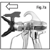
- Ensure the Spray Tip (5) is rotated forward to the spray position with the arrow on the tip facing forward (Fig.7a).
- Perform "Pressure Relief Procedure" section.
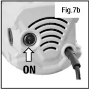
- Turn ON the machine by pressing "I" on the On/Off Switch (13) (Fig.7b).
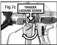
- Unlock the Spray Gun Trigger (3) (Fig.7c).
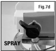
- Set the Prime/Spray Switch (11) to "SPRAY" position (Fig.7d).
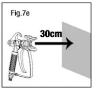
- Stand about 30cm away from area to be sprayed and maintain this distance (Fig.7e).
Pull the spray gun Trigger (3) to start spraying.
NOTE: The motor will cycle ON and OFF while spraying to regulate pressure. This is normal.
IMPORTANT! When finished spraying, perform Pressure Relief Procedure found on page 13.
IMPORTANT! If you have not finished painting with your airless sprayer and want to take a short break (30-60 minutes), do not leave paint sitting inside the pump. Follow the cleaning instructions on pages 24-26 to prevent paint from drying inside the pump and hose.
Once you're ready to begin work again, simply follow the Spraying Procedures on page 20-21. Once properly primed again, aim the spray gun into a waste bucket and allow 30 seconds for any leftover cleaning solution to be flushed out of the system. Then resume painting as normal.
IMPORTANT! Mineral Turpentine SHOULD NOT be mixed with water at any stage during the cleaning process.
Test Spray Settings
NOTE: Ensure you follow the "Spraying Procedure" instructions on pages 20-21 before testing the spraying settings of the Airless Spray Station.
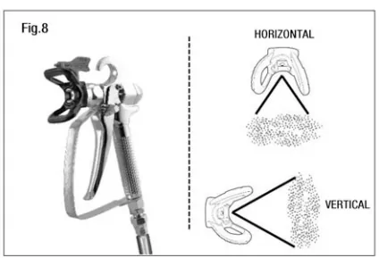
Aligning Spray:
- Follow the "Pressure Relief Procedure" instructions on page 18.
- Rotate the Nozzle Guard (4) to match the direction of the preferred spray pattern (Fig.8).
Spraying Technique
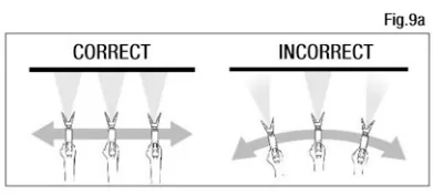
- Move the Spray Gun (6) with the entire arm, not by flexing the wrist. This will keep the Spray Gun (6) at right angles to the surface, keeping the pattern even (Fig.9a).
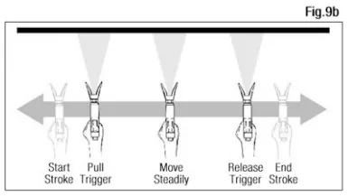
- Pull the spray gun Trigger (3) after starting the stroke, and release the Trigger (3) before ending the stroke. The Spray Gun (6) should be moving when the Trigger (3) is pulled and released (Fig.9b).
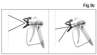
- Keep the Spray Gun (6) perpendicular to the surface, so spray distance is consistent (Fig.9c).
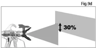
- Overlap your strokes by 30% to ensure even coverage (Fig.9d).
HINTS:
- Do not spray outdoors on a windy day as the results may be unsatisfactory.
- Only apply one coat at a time, always allow a coat to completely dry before adding another coat.
- Avoid stopping and starting as this can lead to a patchy finish. It is best to start spraying outside the surface to be sprayed and avoid stopping in the middle of the surface, continue just past the opposite edge.
Cleaning
Select Cleaning Solution
For WATER-BASED material (e.g. acrylic paint):
- Use ONLY water when performing the cleaning procedure.
- WARNING! Use of a solvent-based cleaning materials on water-based paints will result in a new substance that will be extremely difficult to clean.
- We recommend the use of 10-15 litres of water when performing the cleaning procedure.
For OIL-BASED material (e.g. enamel paint, lacquer):
- Use ONLY the appropriate cleaning solution. Read the cleaning instructions printed on the coating material's label to determine which cleaning material you need.
- The following solvent-based cleaning products are safe to use in the airless spray station:
- Mineral Turpentine
- Paint Thinner.
- NOTE: Mineral Turpentine SHOULD NOT be mixed with water at any stage during the cleaning process.
- We recommend 1-2 litres of the appropriate solvent-based cleaner when performing cleaning procedure.
Cleaning the Unit
IMPORTANT! The cleaning process must be followed immediately after use to prevent paint from drying inside the pump and hose. Failure to follow the cleaning instructions promptly may permanently seize the paint sprayer and automatically void the warranty.
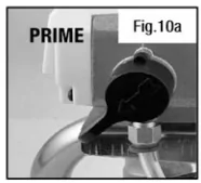
- Set the Prime/Spray Switch (11) to the "PRIME" position (Fig.10a).
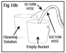
- Place the Suction Hose (16) into a bucket of appropriate cleaning solution. Place the Return Hose (13) into an empty bucket (Fig.10b).
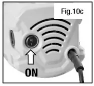
- Turn ON the machine by pressing "1" on the On/Off Switch (10) (Fig.10c). Check the Return Hose (13) and wait for a constant stream of cleaning solution to pass out of it.
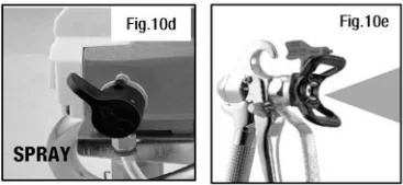
- Set the Prime/Spray Switch (11) to "SPRAY" position (Fig.10d).
- Aim the Spray Gun (6) into an empty bucket, then squeeze and hold the Trigger (3) until most of the paint is removed from the Spray Hose (1).
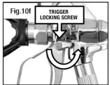
- Lock the spray gun Trigger (3) (Fig.10f).
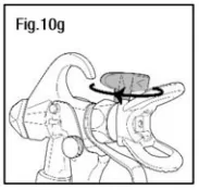
- Rotate the Spray Tip (5) 180° towards the Spray Gun Handle (7) (Fig.10g).
- Unlock the spray gun Trigger (3) and hold the Trigger (3) to spray the cleaning solution through the system (Fig.10h).
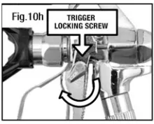
Continue spraying until only cleaning solution is ejected from the Spray Tip (5). Add more cleaning solution if all the paint has not been removed.
NOTE: If the cleaning solution bucket becomes cloudy with paint during this cleaning process, skip to section "Cleaning the Suction Hose Filter" on page 26. Once the Suction Hose Filter (15) and Spray Hose (1) are clean, re-assemble them and repeat steps 4 to 8 in this section.
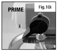
- Set the Prime/Spray Switch (11) to the "PRIME" position (Fig.10i).
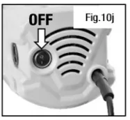
- Switch OFF the machine by pressing "O" on the On/Off Switch (10) (Fig.10j).
Cleaning the Suction Hose Filter
IMPORTANT! The cleaning process must be followed immediately after use to prevent paint from drying inside the pump and hose. Failure to follow this instruction may permanently seize the paint sprayer and automatically void the warranty.
- Unscrew the Suction Hose Filter (15) from the Suction Hose (16) (Fig.11a).
Clean the Suction Hose Filter (15) with the appropriate cleaning solution (Fig.11b).
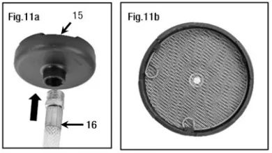
- Thread the Suction Hose Filter (15) back onto the Suction Hose (16) once it has also been cleaned.
Cleaning the Spray Gun
IMPORTANT! The cleaning process must be followed immediately after use to prevent paint from drying inside the pump and hose. Failure to follow this instruction may permanently seize the paint sprayer and automatically void the warranty.
WARNING! Ensure the unit is switched OFF and the Pressure Release Procedure has been performed.
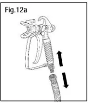
- Remove the Spray Gun (6) from the Spray Hose (1) by loosening the nut with the supplied wrench (Fig.12a).
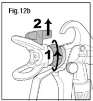
- Remove the Nozzle Guard (4) and Spray Tip (5) from the Spray Gun (6) by loosening the nut. Once the guard assembly has been removed, pull the Spray Tip (5) out (Fig.12b).
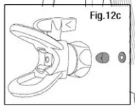
NOTE! A small spacer and washer are used to locate the Spray Tip (5) within the Nozzle Guard (4). Be careful not to lose these components when the Nozzle Guard (4) is removed (Fig.12c).
- Unhook the Trigger Guard (2) from the Spray Gun Handle (7).
- While holding the upper body of the Spray Gun (6), loosen the Spray Gun Handle (7) using a wrench over the grooves located on the bottom part of the Spray Gun Handle (7). Rotate anti-clockwise until the Spray Gun Handle (7) can be completely removed (Fig.12d).
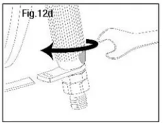
TIP: Using a shifter or bench vice to hold the upper body of the Spray Gun (6) will make this step much easier.
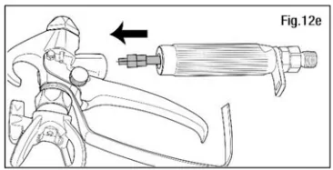
- Remove the mesh filter from the Handle (7) and clean all components in the cleaning solution (Fig.12e).
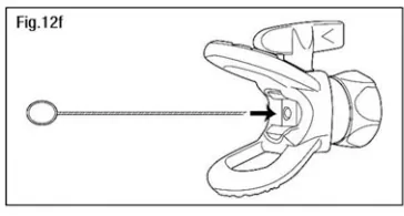
- If the Spray Tip (5) is blocked, use the cleaning pin by inserting it into the Spray Tip (5) (Fig.12f).
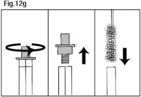
- To clean the mesh filter, unscrew either cap end by turning anti-clockwise. Once unscrewed, remove the cap and pull the other cap and spring out of the mesh filter sleeve. Use the cleaning brush to scrub the inside of the mesh filter (Fig.12g).
NOTE: After cleaning, inspect the condition of the mesh filter. If the mesh filter is clogged with dried paint, has started fraying or has deformed out of shape, it will need to be replaced.
- To re-assemble the Spray Gun (6), follow the procedures above in reverse.
Maintenance & Storage
Assembling the Spray Tip & Nozzle Guard to Spray Gun
NOTE: The Spray Gun (6) comes assembled from the factory. If the Spray Gun (6) has been disassembled for cleaning, follow the steps below to re-assemble.
- Insert the mesh filter into the Handle (7) and align the Handle (7) with the upper body of the Spray Gun (6) (Fig.13a).
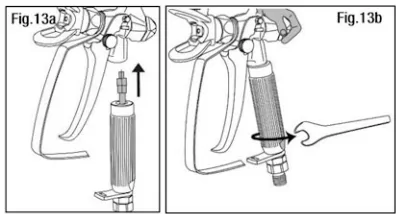
- While holding the upper body of the Spray Gun (6), tighten the Handle (7) using the supplied wrench (Fig.13b).
- Hook the bottom edge of the Trigger Guard (2) into the hole in the Handle.
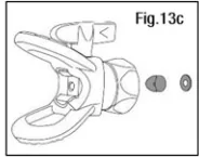
- Ensure the small spacer and washer that locate the Spray Tip (5) are inserted in the Nozzle Guard (4) (Fig.13c).
- Place Trigger Guard (2) over the end of Spray Gun (step 1) and insert Spray Tip (5) into the Trigger Guard (step 2) (Fig.13d).
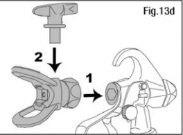
Make sure that the Spray Tip (5) is rotated forward to the spray position with the arrow on the tip facing forward.
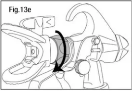
- Tighten the retaining nut (Fig.13e).
WARNING! Do not spray without the Spray Tip (5) and Nozzle Guard (4) in place. Do not press the Trigger (3) unless the Spray Tip (5) is correctly installed in the spray position. Always lock the Trigger (3) before removing, replacing or cleaning the Spray Tip (5).
Long Term Storage
WARNING! Follow all cleaning procedures after each use. Ensure the unit is thoroughly cleaned before storing to prevent build-up of dried paint which may cause blockages and stop the unit from working.
- Perform ALL cleaning procedures found on pages 24-26.
- Remove the Spray Hose (1).
- Remove the Suction Hose (16) from the Suction Hose Inlet Port (17) by squeezing the dogleg pin.
- Remove the Return Hose (13) from the Return Hose Inlet Port (12) by unscrewing the nut.
- Turn the machine upside down. Add 30m/s of household oil or a pump protector oil into each inlet port.
- Set the Prime/Spray Switch (11) to "SPRAY" position.
- Hold a rag over the Spray Hose Outlet Port (18).
- Switch ON the machine for 5 SECONDS by pressing the "I" on the On/Off Switch (10).
Then Switch OFF the machine by pressing the "O" on the On/Off Switch (10).
- Set the Prime/Spray Switch (11) to "PRIME" position.
- Replace the Suction Hose (16) to the Suction Hose Inlet Port (17), and use the dogleg pin to secure the Suction Hose (16) in place.
- Replace the Return Hose (13) to the Return Hose Inlet Port (12).
- Wipe the sprayer housing with a clean dry cloth.
- Store the sprayer and its accessories in a clean, dry location, out of the reach of children.
Troubleshooting
| PROBLEM |
POSSIBLE CAUSES |
SUGGESTED SOLUTIONS |
| The sprayer does not turn ON. |
The mains power lead is not plugged in. |
Plug the mains power lead into a mains power outlet. |
| No voltage is coming from the mains power outlet. |
Properly test the power supply voltage. |
| The ON/OFF Switch (10) is set to OFF. |
Turn the ON/OFF Switch (10) to ON. |
| The extension cord is damaged or has too low capacity. |
Replace the extension cord with a suitable voltage. |
| Little or no material flow. |
Spray Tip (5) is clogged. |
Clean Spray Tip (5) using cleaning pin. |
| Suction Hose (16) is clogged. |
Clean Suction Hose (16). |
| Suction Hose (16) is loose at the Suction Hose inlet Port. |
Clean the Suction Hose (16) connections and tighten securely. |
| Suction Hose Filter (15) clogged. |
Clean or replace Suction Hose Filter (15). Use the appropriate cleaning solution depending on the material used (refer to page 24). |
| The Spray Tip leaks |
The Nozzle Guard (4) nut is loose. |
Tighten the Nozzle Guard (4) nut. |
| Spray Tip (5) was assembled incorrectly. |
Remove Spray Tip (5) and assemble correctly. |
| Spray Tip (5) is worn. |
Replace the Spray Tip (5). |
| Atomization is too coarse. |
Spray Tip (5) and Nozzle Guard (4) clogged. |
Clean. |
| Suction Hose Filter (15) clogged. |
Clean or replace. |
| Material leaking. |
Nozzle Guard (4) is loose. |
Tighten the Nozzle Guard (4). |
| Spray Tip (5) is worn. |
Replace the Spray Tip (5). |
| Seal inside the Nozzle Guard (4) worn. |
Replace the seal. Contact After Sales Support. |
| Material building up inside Spray Tip (5) and Nozzle Guard (4). |
Clean using the appropriate cleaning solution depending on the material used (refer to page 24). |
| Pattern runs or sags. |
Applying too much material. |
Increase movement of Spray Gun (6). |
| Too much over-spray. |
Gun too far from spray object. |
Reduce distance. |
| Pattern is very light and blotchy. |
Moving the Spray Gun (6) too fast. |
Decrease movement of Spray Gun (6). |
| Spluttering paint. |
Air bubbles in the Return Hose (13). |
Perform "Priming the Pump" steps. |
| Suction Hose (11) not sucking up water when cleaning the unit. |
Lack of pressure. |
Using the appropriate cleaning solution in place of material, perform the "Priming the Pump" steps. |
| The paint pattern is tailing. |
The spray gun Mesh Filter, the Spray Tip (5), or the Suction Hose Filter (15) is clogged. |
Clean spray gun Mesh Filter, the Spray Tip (5), and the Suction Hose Filter (15). |
| The Suction Hose (16) is loose at the Suction Hose Inlet Port (17). |
Re-adjust the Suction Hose (16) to the Suction Hose Inlet Port (17). |
| The Spray Tip (5) is worn. |
Replace the Spray Tip (5). |
| The paint is too thick. |
Thin the paint according to the manufacturer's instructions. |
Technical Specifications
Mains Voltage: 230V 50Hz
Rated Power: 1010W
Rated Input Current: 4.63-4.78A
Maximum Working Pressure: 3000 PSI (22.7 Mpa)
Max. Flow Rate: 1.5 l/min
Spray Hose Length: 7.5m
IP Rating: IPXO
Spray Tip Size: 515
Material/Paint Temperature: 10 - 40°C
Class Rating: II
Sound Power Value: 110 dB(A)
Disposal Instructions
Tools that are no longer usable should not be disposed of with household waste but in an environmentally friendly way. Please recycle where facilities exist in your area. Check with your local council authority for recycling advice.
Dispose of hazardous waste, such as paint, varnishes and thinners safely. Contact your local council authority for advice on disposal and recycling services.
Recycling packaging reduces the need for landfill and raw materials. Reuse of recycled material decreases pollution in the environment. Please recycle packaging where facilities exist. Check with your local council authority for recycling advice.
Limited Liability & Warning
No Unauthorized Modifications/Repairs: Do not modify or attempt to repair this product unless you are an authorized technician. Unauthorized actions may create hazards and void all warranties.
Misuse & Non-Compliance: We are not liable for any injury, damage, or loss resulting from:
(a) misuse, abuse, neglect, or improper installation;
(b) failure to follow instructions or safety precautions;
(c) use of unauthorized parts/accessories;
(d) unauthorized modifications/repairs;
(e) accidents, natural disasters, or external causes.
If you doubt any step of installation or operation, stop using the product and contact authorized service or the customer support.