ControlMax
™
0917 • Form No. 0580356D
Airless, high-pressure
sprAying unit
AppAreil De pulVÉrisAtiOn
À hAute pressiOn sAns Air
uniDAD De
pulVeriZACiÓn sin Aire
y De AltA presiÓn
- F - guiDe D’utilisAtiOn 24
- es - mAnuAl Del usO 46
OperAting mAnuAl
2
EN
IMPORTANT SAFETY INFORMATION
Read all safety information before operating the equipment.
Save these instructions.
To reduce the risks of re or explosion, electrical shock and the
injury to persons, read and understand all instructions included
in this manual. Be familiar with the controls and proper usage
of the equipment.
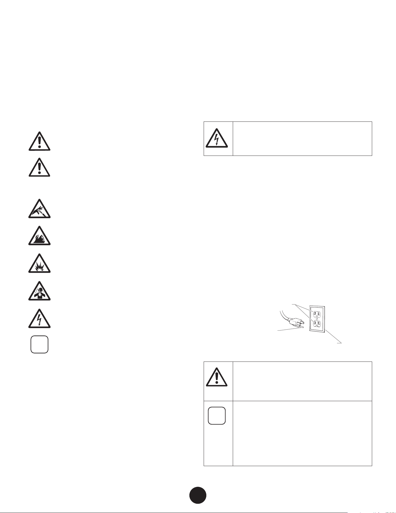
EXPLANATION OF SYMBOLS
This symbol indicates a potential hazard
that may cause serious injury or loss of life.
Important safety information will follow.
At
tention
This symbol indicates a potential hazard
to you or to the equipment. Important
information that tells how to prevent
damage to the equipment or how to avoid
causes of minor injuries will follow.
Danger of skin injection
Danger of re from solvent and paint fumes
Danger of explosion from solvent, paint
fumes and incompatible materials
Danger of injury from inhalation of harmful
vapors
Electric shock hazard
i
Notes give important information which
should be given special attention.
GROUNDING INSTRUCTIONS
This product must be grounded. In the event of an electrical
short circuit, grounding reduces the risk of electric shock by
providing an escape wire for the electric current. This product
is equipped with a cord having a grounding wire with an
appropriate grounding plug. The plug must be plugged into
an outlet that is properly installed and grounded in accordance
with all local codes and ordinances.
WARNING - Improper installation of the
grounding plug can result in a risk of electric
shock.
If repair or replacement of the cord or plug is necessary, do not
connect the green grounding wire to either at blade terminal.
The wire with insulation having a green outer surface with
or without yellow stripes is the grounding wire and must be
connected to the grounding pin.
Check with a qualied electrician or serviceman if the grounding
instructions are not completely understood, or if you are in
doubt as to whether the product is properly grounded. Do not
modify the plug provided. If the plug will not t the outlet,
have the proper outlet installed by a qualied electrician.
This product is for use on a nominal 120 volt circuit and has a
grounding plug that looks like the plug illustrated below. Make
sure that the product is connected to an outlet having the same
conguration as the plug. No adapter should be used with this
product.
Grounded Outlet
Grounding Pin
Cover for grounded outlet box
At
tention
When the sprayer is used with a generator or
uncontrolled line voltage, the use of Titan’s “Line
Surge Protector” (P/N 800-935) is recommended.
i
Make sure to check for grounding continuity
after service is performed on any electrical
components.
Use an ohmmeter to determine that there is
continuity between accessible dead-metal parts
of the product and the grounding blade of the
attachment plug.
EN
3
IMPORTANT SAFETY INFORMATION
SAFETY hAzARDS
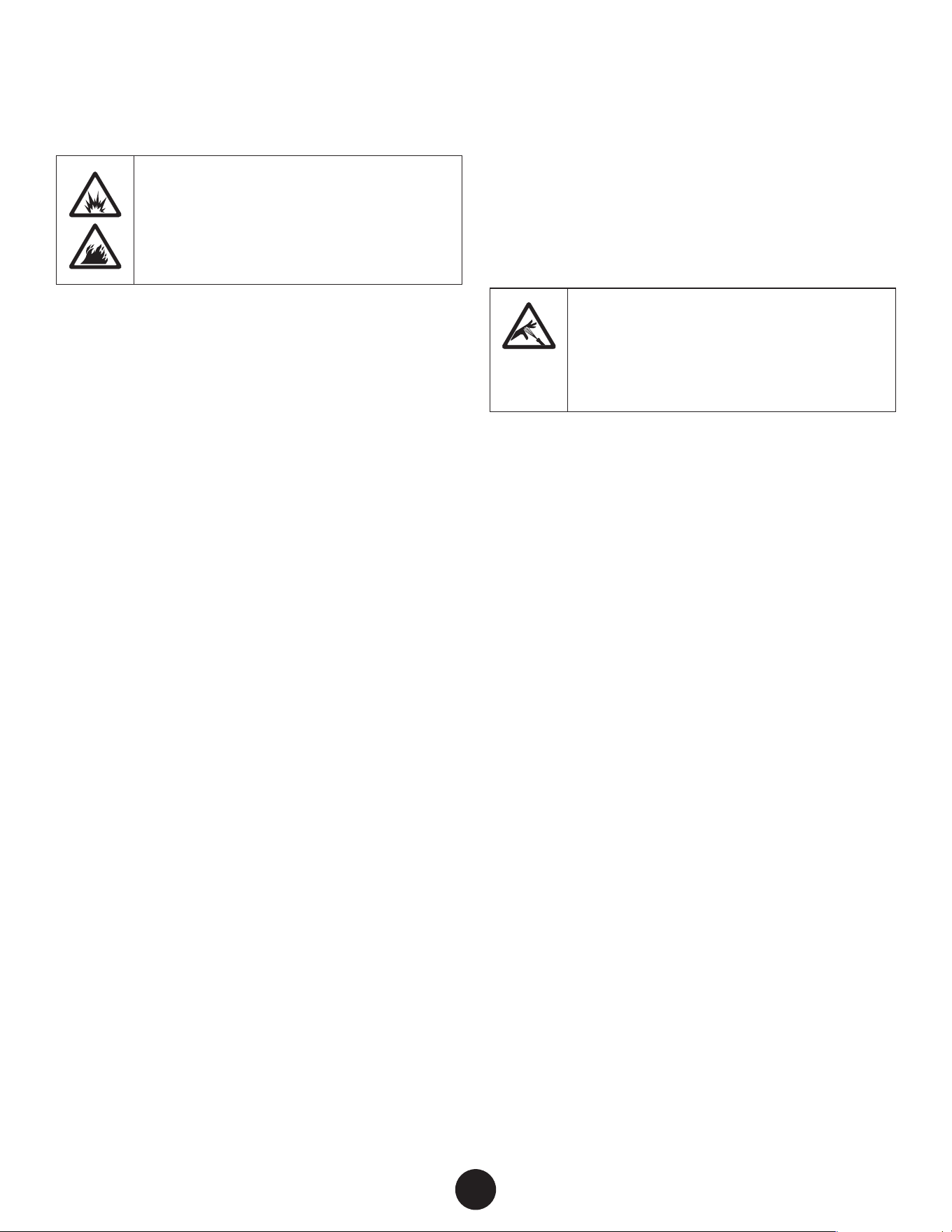
warning: EXPLOSiOn Or FirE
Solvent and paint fumes can explode or ignite.
Severe injury and/or property damage can occur.
PrEVEnTiOn:
• Do not spray ammable or combustible materials near
an open ame, pilot lights or sources of ignition such
as hot objects, cigarettes, motors, electrical equipment
and electrical appliances. Avoid creating sparks from
connecting and disconnecting power cords.
• Do not spray or clean with liquids having a ash point of
less than 38ºC (100ºF). Flash point is the temperature at
which a uid can produce enough vapor to ignite.
• Paint or solvent owing through the equipment is able to
result in static electricity. Static electricity creates a risk of
re or explosion in the presence of paint or solvent fumes.
All parts of the spray system, including the pump, hose
assembly, spray gun and objects in and around the spray
area shall be properly grounded to protect against static
discharge and sparks. Use only conductive or grounded
high-pressure airless paint sprayer hoses specied by the
manufacturer.
• Verify that all containers and collection systems are
grounded to prevent static discharge.
• Connect to a grounded outlet and use grounded extension
cords (electric models only). Do not use a 3 to 2 adapter.
• Do not use a paint or solvent containing halogenated
hydrocarbons. Such as chlorine, bleach mildewcide,
methylene chloride and trichloroethane. They are not
compatible with aluminum. Contact the coating supplier
about compatibility of material with aluminum.
• Keep spray area well ventilated. Keep a good supply of
fresh air moving through the area to keep the air within the
spray area free from accumulation of ammable vapors.
Keep pump assembly in well ventilated area. Do not spray
pump assembly.
• Do not smoke in the spray area.
• Do not operate light switches, engines, or similar spark
producing products in the spray area.
• Keep area clean and free of paint or solvent containers,
rags, and other ammable materials.
• Know the contents of the paint and solvents being sprayed.
Read all material Safety Data Sheets (SDS) and container
labels provided with the paints and solvents. Follow the
paint and solvent manufacture’s safety instructions.
• Place pump at least 20 feet (6 meters) from the spray object
in a well ventilated area (add more hose if necessary).
Flammable vapors are often heavier than air. Floor area
must be extremely well ventilated. The pump contains
arcing parts that emit sparks and can ignite vapors.
• Plastic can cause static sparks. Never hang plastic to
enclose spray area. Do not use plastic drop cloths when
spraying ammable material.
• Fire extinguisher equipment shall be present and working.
warning: injEcTiOn injury
A high pressure paint stream produced by this
equipment can pierce the skin and underlying
tissues, leading to serious injury and possible
amputation. See a physician immediately.
PrEVEnTiOn:
• Do not aim the gun at, or spray any person or animal.
• Keep hands and other body parts away from the discharge.
For example, do not try to stop leaks with any part of the
body.
• NEVER put your hand in front of the gun. Gloves will not
provide protection against an injection injury.
• ALWAYS keep the tip guard in place while spraying. The tip
guard provides some protection but is mainly a warning
device.
• Only use a nozzle tip specied by the manufacturer.
• Use caution when cleaning and changing nozzle tips. In
the case where the nozzle tip clogs while spraying, ALWAYS
lock gun trigger, shut pump o, and release all pressure
before servicing, cleaning tip or guard, or changing tip.
Pressure will not be released by turning o the motor. The
PRIME/SPRAY valve or pressure bleed valve must be turned
to their appropriate positions to relieve system pressure.
Refer to PRESSURE RELIEF PROCEDURE described in the
pump manual (page 9).
• Do not leave the unit energized or under pressure while
unattended. When the unit is not in use, turn o the unit and
relieve the pressure in accordance with the manufacturer’s
instructions.
• High-pressure spray is able to inject toxins into the body
and cause serious bodily injury. In the event that injection
occurs, seek medical attention immediately.
• Check hoses and parts for signs of damage, a leak can inject
material into the skin. Inspect hose before each use. Replace
any damaged hoses or parts. Only use TITAN original-high-
pressure hoses in order to ensure functionality, safety and
durability.
• This system is capable of producing 1600 PSI / 11.1 MPa.
Only use replacement parts or accessories that are specied
by the manufacturer and that are rated a minimum of
1600 PSI. This includes spray tips, nozzle guards, guns,
extensions, ttings, and hose.
4
EN
IMPORTANT SAFETY INFORMATION
• Always engage the trigger lock when not spraying. Verify
the trigger lock is functioning properly.
• Verify that all connections are secure before operating the
unit.
• Know how to stop the unit and bleed pressure quickly. Be
thoroughly familiar with the controls. Pressure will not be
released by turning o the motor. The PRIME/SPRAY valve
or pressure bleed valve must be turned to their appropriate
positions to relieve system pressure. Refer to PRESSURE
RELIEF PROCEDURE described in the pump manual (page 9).
• Always remove the spray tip before ushing or cleaning
the system.
i
NOTE TO PHYSICIAN:
Injection into the skin is a traumatic injury which
can lead to possible amputation. It is important
to treat the injury as soon as possible. DO NOT
delay treatment to research toxicity. Toxicity is
a concern with some coatings injected directly
into the blood stream. Consultation with a plastic
surgeon or reconstructive hand surgeon may be
advisable.
warning: HaZarDOuS VaPOrS
Paints, solvents, insecticides, and other materials
can be harmful if inhaled or come in contact
with the body. Vapors can cause severe nausea,
fainting, or poisoning.
PrEVEnTiOn:
• Use a respirator or mask if vapors can be inhaled. Read
all instructions supplied with the mask to be sure it will
provide the necessary protection.
• Wear protective eyewear.
• Wear protective clothing as required by coating
manufacturer.
warning: gEnEraL
Can cause severe injury or property damage.
PrEVEnTiOn:
• Always wear appropriate gloves, eye protection, clothing
and a respirator or mask when painting.
• Do not operate or spray near children. Keep children away
from equipment at all times.
• Do not overreach or stand on an unstable support. Keep
eective footing and balance at all times.
• Stay alert and watch what you are doing.
• Do not operate the unit when fatigued or under the
inuence of drugs or alcohol.
• Do not kink or over-bend the hose. Airless hose can
develop leaks from wear, kinking and abuse. A leak can
inject material into the skin.
• Do not expose the hose to temperatures or pressures in
excess of those specied by manufacturer.
• Do not use the hose as a strength member to pull or lift the
equipment.
• Use lowest possible pressure to ush equipment.
• Follow all appropriate local, state and national codes
governing ventilation, re prevention and operation.
• The United States Government Safety Standards have
been adopted under the Occupational Safety and Health
Act (OSHA). These standards, particularly part 1910 of
the General Standards and part 1926 of the Construction
Standards should be consulted.
• Before each use, check all hoses for cuts, leaks, abrasion
or bulging of cover. Check for damage or movement
of couplings. Immediately replace hose if any of those
conditions exist. Never repair a paint hose. Replace with a
conductive high-pressure hose.
• Do not spray outdoors on windy days.
• Always unplug cord from outlet before working on
equipment (electric models only).
TABLE OF CONTENTS
IMPORTANT SAFETY INFORMATION __________________ 2-4
GENERAL INFORMATION _____________________________ 5
ASSEMBLY _______________________________________ 6-7
PARTS AND COMPONENTS ___________________________ 8
BEFORE YOU BEGIN _________________________________ 9
LOAD MATERIAL ___________________________________ 10
SPRAYING ________________________________________ 11
PRACTICE SPRAYING ____________________________ 12-13
CLEAR THE SPRAY TIP _______________________________ 14
CLEAN THE INLET FILTER ____________________________ 15
SHORT TERM STORAGE _____________________________ 16
CLEANUP ______________________________________ 17-18
LONG TERM STORAGE ______________________________ 19
CLEANING THE INLET VALVE _________________________ 20
CLEANING THE OUTLET VALVE _______________________ 21
TROUBLESHOOTING ________________________________ 22
WARRANTY _______________________________________ 23
PARTS LIST ____________________________________ 68-72
EN
5
GENERAL INFORMATION
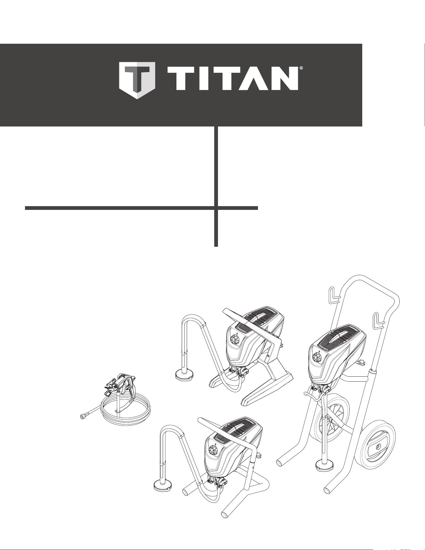
MODELS
This pump is available in stand models (1500 / 1700) and cart
models (1700 Pro / 1900 Pro).
Some of the graphics in this manual may not exactly match
your sprayer and spray gun. All information and instructions
given in this manual applies to all models except where noted.
The type of spray gun and length of spray hose included
depends upon the pump model you have. Refer to the chart
below for details.
Pump Model gun Model Hose Length
ControlMax 1500 Hybrid (plastic/metal
handle)
25 ft.
ControlMax 1700 Hybrid (plastic/metal
handle)
30 ft.
ControlMax 1700 Pro Metal (all metal handle) 50 ft.
ControlMax 1900 Pro Metal (all metal handle) 50 ft.
The ControlMax can only
be used with spray
tips, hoses or spray guns that are ControlMax
compatible. Do not use any non-ControlMax
accessories with this system.
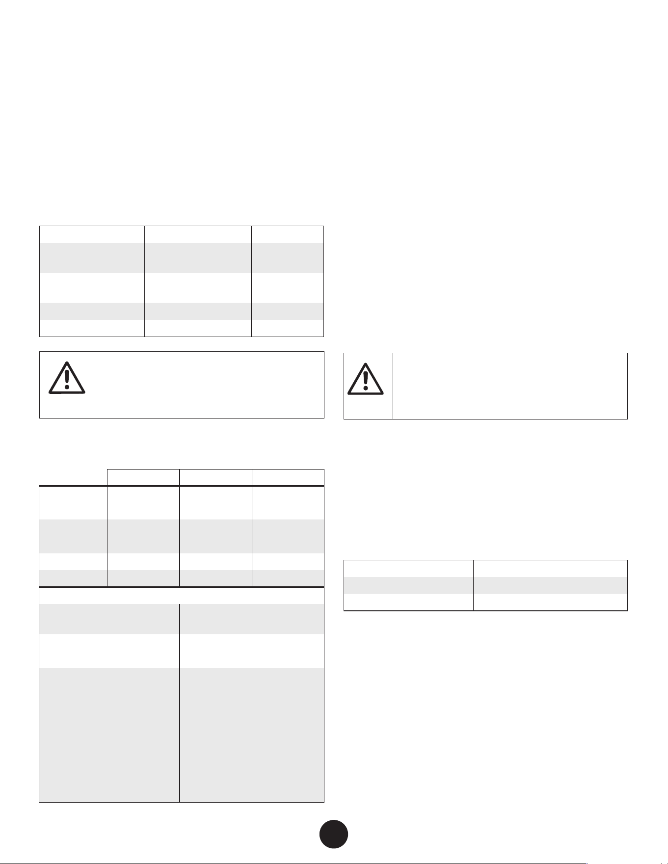
SPECIFICATIONS
1500 1700 1900
Maximum
Pressure
1500 PSI
(10.3 MPa)
1500 PSI
(10.3 MPa)
1600 PSI
(11.1 MPa)
capacity 0.29 GPM
(1.1 LPM)
0.33 GPM
(1.25 LPM)
0.40 GPM
(1.5 LPM)
Max. tip 0.015
0.017 0.019
Horsepower 0.55 0.6 0.7
all models:
Power requirement 15 amp minimum circuit on
115 VAC, 60 Hz current
generator power
requirement
5000 Watt
(disable idle-down feature)
Overheating protection This sprayer has a built-
in protective device to
prevent damage from
overheating. The sprayer
may automatically shut
down after heavy use. If this
happens, turn switch OFF (0),
unplug the sprayer and allow
to cool for 20-30 minutes and
resume spraying.
CAPABILITY
Sprays a variety of paints (oil-based and latex), primers, stains,
preservatives and other nonabrasive materials.
DO NOT USE!
This pump should not be used with textured materials, block
ller, lacquers, industrial enamels, or asphalt sealer or materials
containing HHC. See coating supplier if ash point is not listed
on the container.
SAFETY FEATURES
Spray gun trigger lock and pressure diuser; built-in tip safety
guard; PRIME/SPRAY knob for safe pressure release. Conforms
to UL STD 1450. Certied to CSA C22.2 NO 68.
IMPORTANT ELECTRICAL INFORMATION
At
tention
Use only a 3-wire extension cord that has a
3-blade grounding plug and a 3-slot receptacle
that will accept the plug on the product.
Make sure your extension cord is in good condition. When
using an extension cord, be sure to use one heavy enough to
carry the current your product will draw. An undersized cord
will cause a drop in line voltage resulting in loss of power and
overheating.
A 14 or 12 gauge cord is recommended (see chart). If an
extension cord is to be used outdoors, it must be marked with
“SJW” or “SJTW”. For example, a designation of SJTW would
indicate that the cord would be appropriate for outdoor use.
cord gauge Maximum cord length
12 150 feet
14 100 feet
Titan Tool accessory extension cords recommended:
P/N 0090241 20 foot extension cord
P/N 0090242 35 foot extension cord
1
2
METAL
PLASTIC
3
4
5
ASSEMBLY
6
EN
Do not plug in the power cord until assembly is
complete.
TOOLS NEEDED
• Two 6” adjustable wrenches
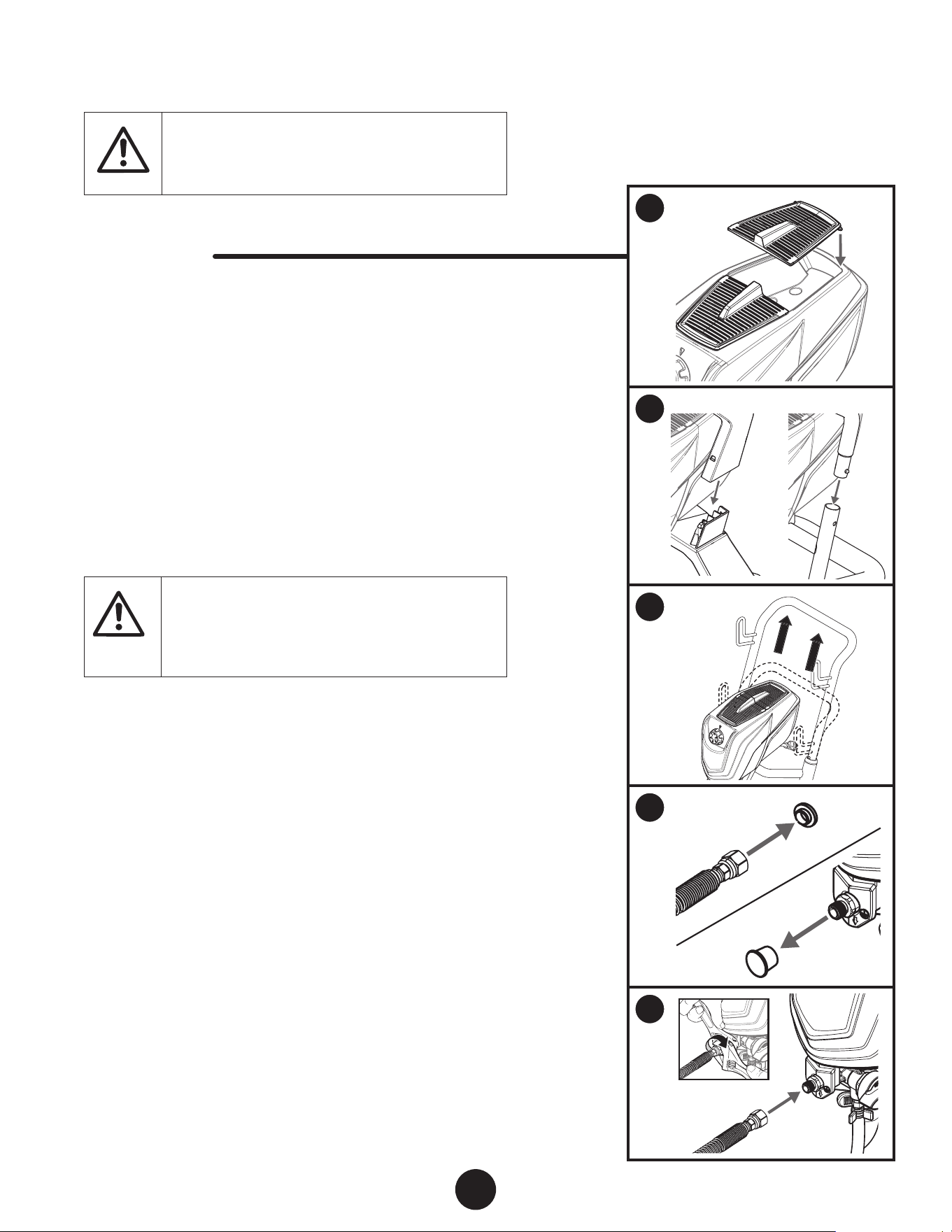
1. Attach the tool box doors to the top of the sprayer as shown.
Snap one peg into one of the orices, and then snap the other
peg into the other orice. The pegs on the ends will snap into
the orices on the unit.
2. STAND MODELS - Attach the handle:
Metal Frame - Line up the handle with the frame as shown.
Push the snap buttons on each side and drop the handle into
the frame. The snap-buttons will secure the handle into place.
Plastic Frame - Align the handle to the tabs on the unit and
press into place until it snaps (no snap buttons).
At
tention
Plastic Frame - Do not attempt to remove the
plastic handle. Removal can damage the snap
connection.
3. CART MODEL - Pull out the handle from the cart frame. Once it
reaches its maximum height, it will snap into place. To push
it back into the frame, push the snap buttons on the back of
the frame.
4. Remove the plug from inside the hose ttings and remove the
cap on the spray hose port. Discard both.
5. Thread one end of the high pressure spray hose to the spray
hose port. Hold the port with an adjustable wrench, and
tighten the hose with the other. Do not over-tighten.
6a
6b
7
8
9
EN
7
ASSEMBLY (CONTINUED)
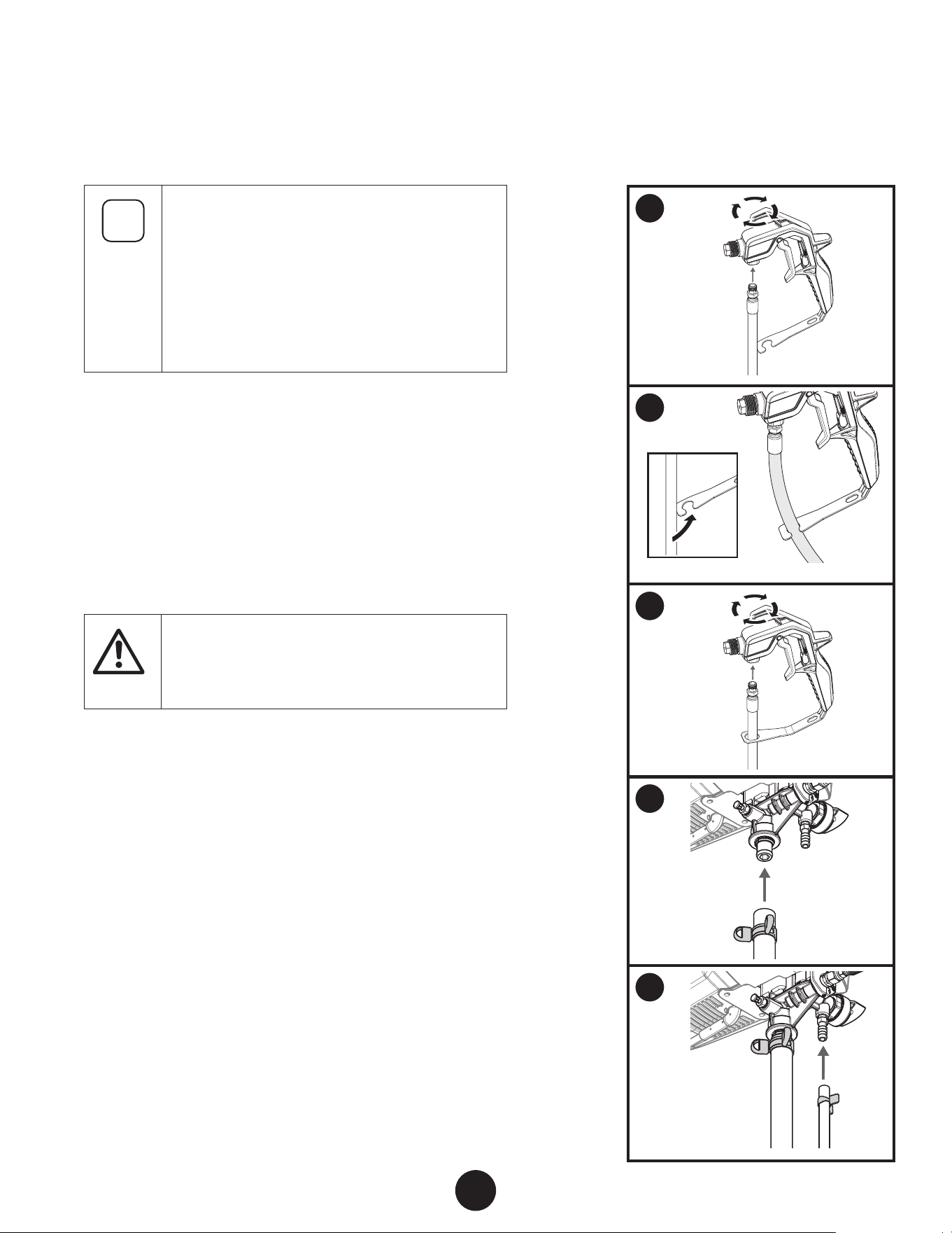
i
The spray gun included with the sprayer will have
one of two types of hose restraint:
1) the “C” type where the hose is clamped, or
2) the circular type where the hose gets threaded
through a hole in the restraint.
When attaching the hose to the spray gun, follow
the appropriate steps to properly secure the spray
hose.
6. “c” type:
a. Spin the gun onto the male tting on the other end of the
spray hose. Turning the gun instead of the hose will make
it easier to align the threads. Tighten the hose end with a
wrench.
b. Press the hose into the opening in the restraint at the bottom
of the gun handle. The hose will ex slightly to t through
the smaller opening and then “pop” into place with no strain
remaining on the hose.
At
tention
Do not kink the hose when attaching it to the gun
or when placing it into the restraint.
7. circular type:
Thread the end of the hose through the hole in the restraint
and into the bottom of the spray gun body as shown. Spin
the gun onto the male tting of the spray hose.
8. Slide the suction tube onto the inlet valve. Secure with the
suction tube clamp.
9. Press the return tube onto the return tube tting. Squeeze
hose clamp over the return tube tting to secure the return
tube.
8
EN
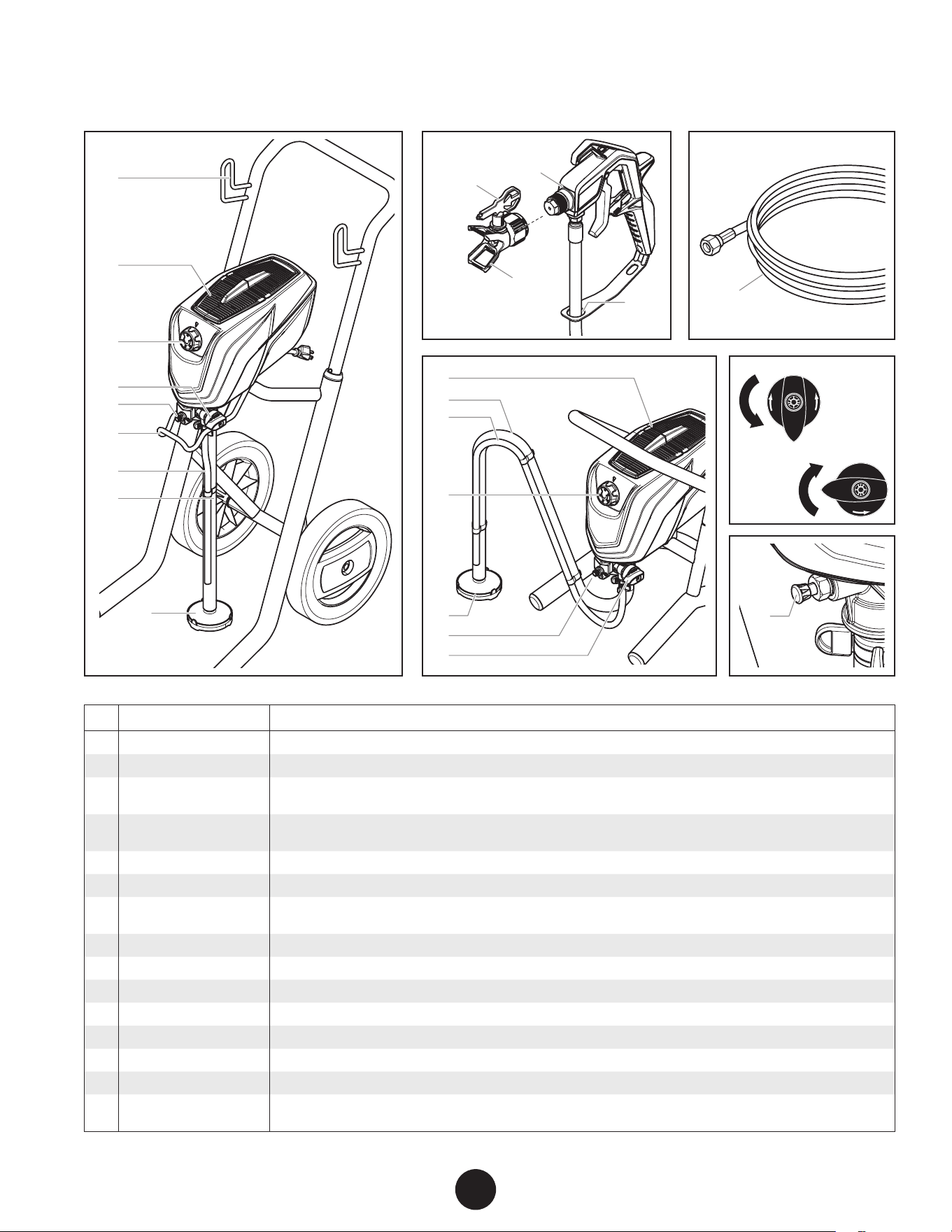
PARTS AND COMPONENTS
SPRAY
PRIME
SPRAY
PRIME
4
2
5
8
2
7
3
9
15
5
4
6
3
7
8
9
1
4
10
12
11
14
SPRAY
PRIME
13
# ITEM DESCRIPTION
1 Hose wrap The hose wrap allows for easy storage of the spray hose (cart models only).
2 Tool box The Tool Box provides a place for items such as extra spray tips or wrenches.
3 Pressure control knob /
ON/OFF switch
The pressure control knob regulates the amount of force the pump uses to push the uid and can be
adjusted for desired spray pattern. Also used to switch the pump ON / OFF.
4 PRIME/SPRAY knob The PRIME/SPRAY knob directs material to the material return tube when set to PRIME or to spray hose
when set to SPRAY.
5 Spray hose port The connection between the pump and the spray hose.
6 Pail bracket
The pail bracket allows for easy transport of the material container (cart models only).
7 Material return tube Fluid is sent out through the return tube and back into the original container when the PRIME/SPRAY
knob is in the PRIME position.
8 Suction tube The suction tube draws the uid from the original container into the pump.
9 Inlet lter The inlet lter is designed to prevent any debris that may be in the spray material from entering the pump.
10 Spray gun The spray gun controls the delivery of the material being pumped.
11 Tip guard The spray guard reduces the risk of injection injury.
12 Spray tip The spray tip atomizes the spray material and forms the spray pattern.
13 Hose restraint This retains the hose for easier use and storage.
14 Spray hose The spray hose connects the spray gun to the pump.
15 Pusher stem The pusher stem is designed to free the inlet valve which may become stuck due to dried materials. The
pusher stem is activated manually by the user.
1
2
1
2
SPRAY
PRIME
3
4 5
EN
9
BEFORE YOU BEGIN
i
This section contains instructions that will be
repeated throughout this manual. Read and
understand this section before using the equipment.
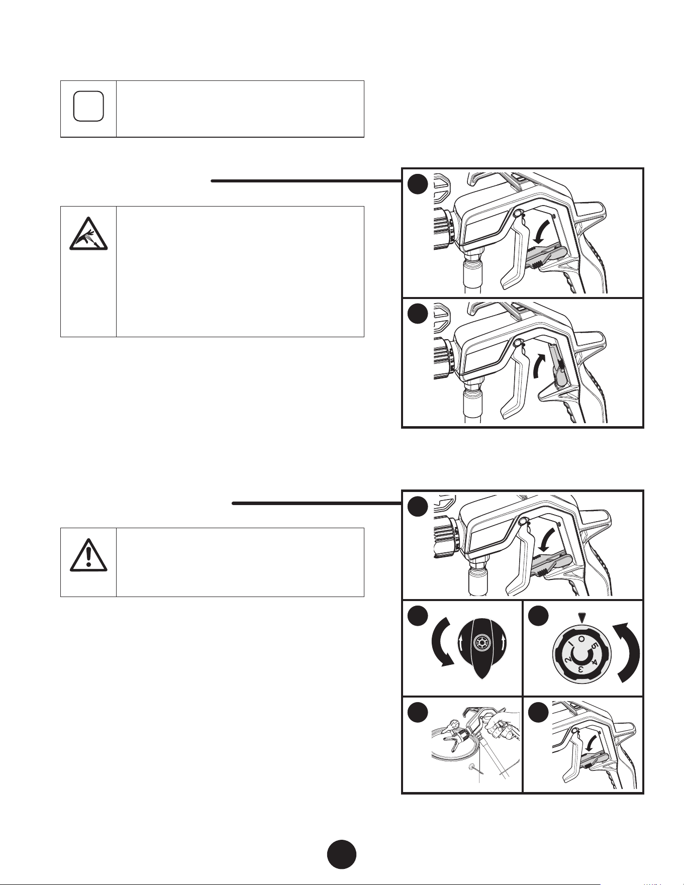
SPRAY GUN TRIGGER LOCk
Be careful when handling the spray gun so you do
not accidently spray yourself.
The high pressure paint stream could pierce your
skin causing serious injury. If an accident happens
see detail procedures in the Safety Information
section on pages 3-4.
See physician immediately and bring this instruction
manual.
Engage the trigger lock whenever instructed.
1. To lock the trigger, ip the trigger lock down until it stops in
place behind the trigger.
2. To unlock the trigger, ip the trigger lock up until it snaps into
place on the gun handle.
PRESSURE RELIEF PROCEDURE
Be sure to follow the Pressure Relief Procedure
when shutting the unit o for any purpose. This
procedure is used to relieve pressure from the spray
hose. Failure to do so could result in serious injury.
Perform the Pressure Relief Procedure whenever instructed.
1. Lock the spray gun (see “Spray Gun Trigger Lock”, above).
2. Turn the PRIME/SPRAY knob to PRIME (see item 4, previous
page).
3. Turn the power OFF (turn pressure control knob to “0”).
4. Unlock the spray gun. Briey pull the trigger to fully relieve
pressure from the system.
5. Lock the spray gun.
1
2
A
B
3
SPRAY
PRIME
4
A
B
5
10
EN
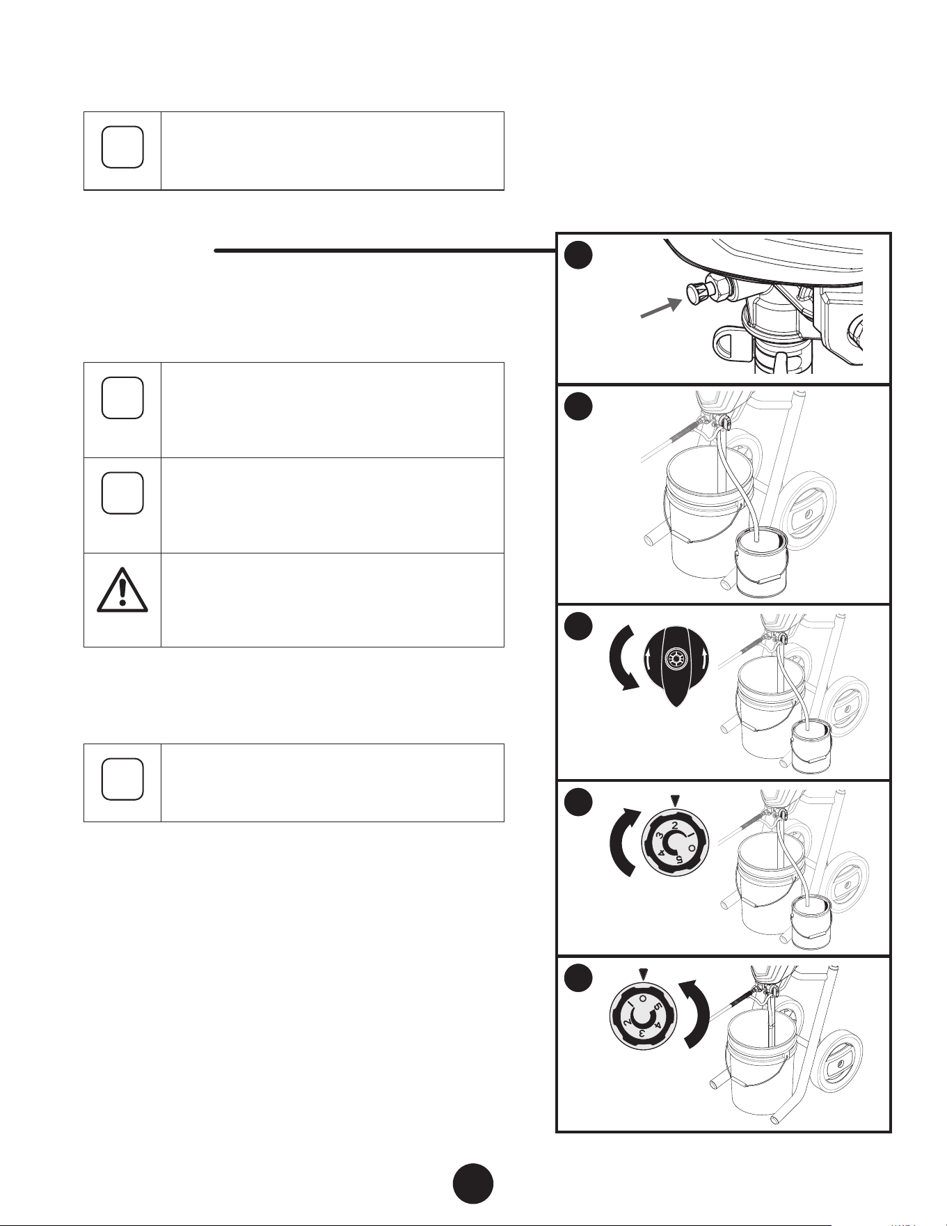
LOAD MATERIAL
i
These steps will prime the system and get it ready
to spray.
YOU wILL NEED
• The material you plan to spray
• Extension cord
• Waste bucket
i
recommendation:
It is good practice to perform
the steps on this page using water to familiarize
yourself with the function of the unit as well as to
ensure the unit is set up properly.
i
recommendation: Always use new spray material
or material that has been thoroughly strained. Old
material often contains debris that can clog the
system.
At
tention
Take care to prevent material spills. Make sure
to use drop cloths or mask anything that is in the
spraying area and could accidentally be sprayed.
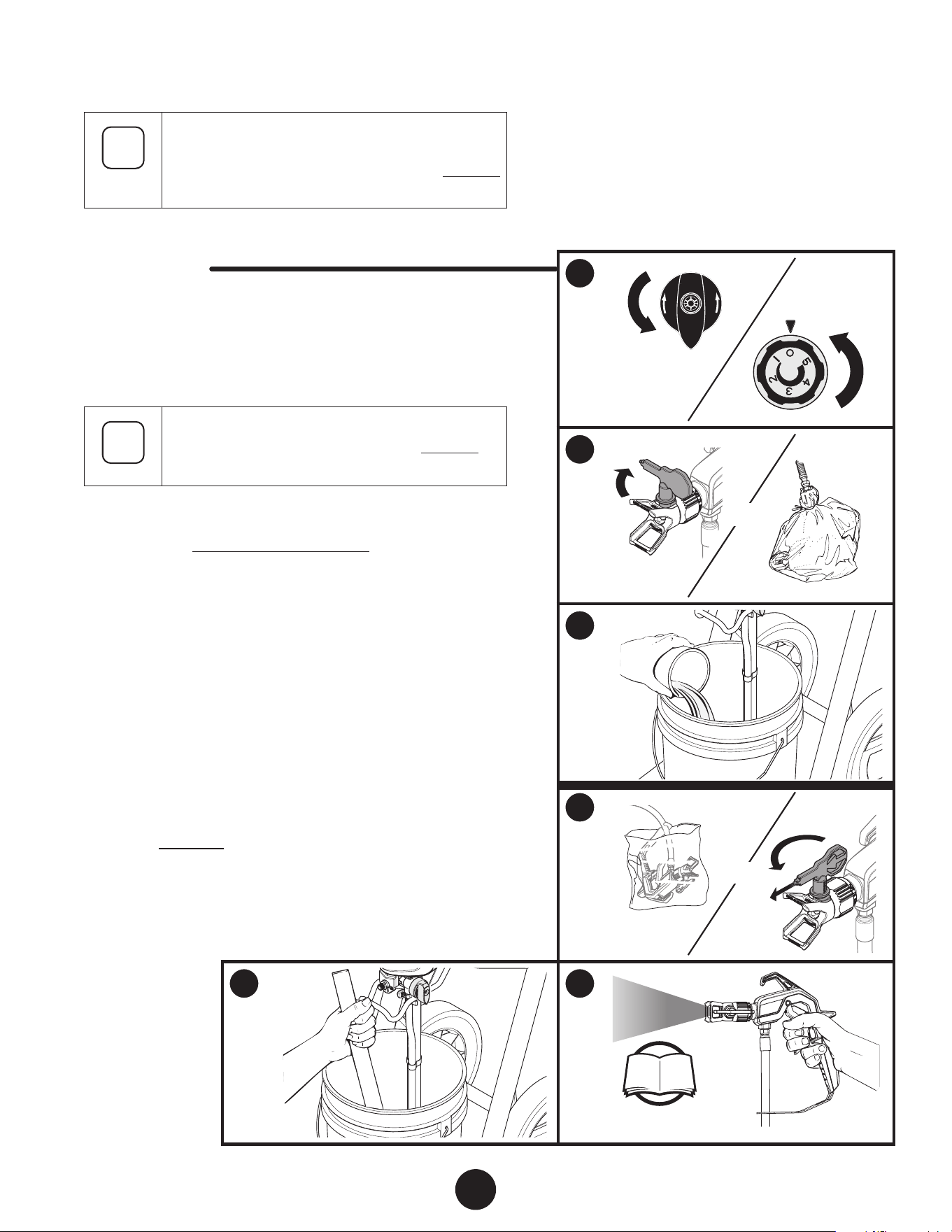
1. Fully depress the pusher stem to make sure the inlet ball is
free.
i
The pusher stem will only travel approximately 1/8”
and will automatically return back to its original
position once released.
2. Place a full container of spraying material underneath the
suction tube (A). Hold the return tube into a waste container
(B).
3. Turn the PRIME/SPRAY knob to PRIME.
4. Plug in the sprayer and slowly turn the pressure control knob
clockwise to setting ‘2’.
Allow pump to run until you see spray material owing from
the return tube (B).
5. Switch the pump OFF (0) by turning the pressure control knob
completely counterclockwise.
Place return tube back into material container and clip return
tube and suction tube together.
1
2
SPRAY
PRIME
3
4
SPRAY
PRIME
5
OR
6
OR
7
SPRAY
PRIME
EN
11
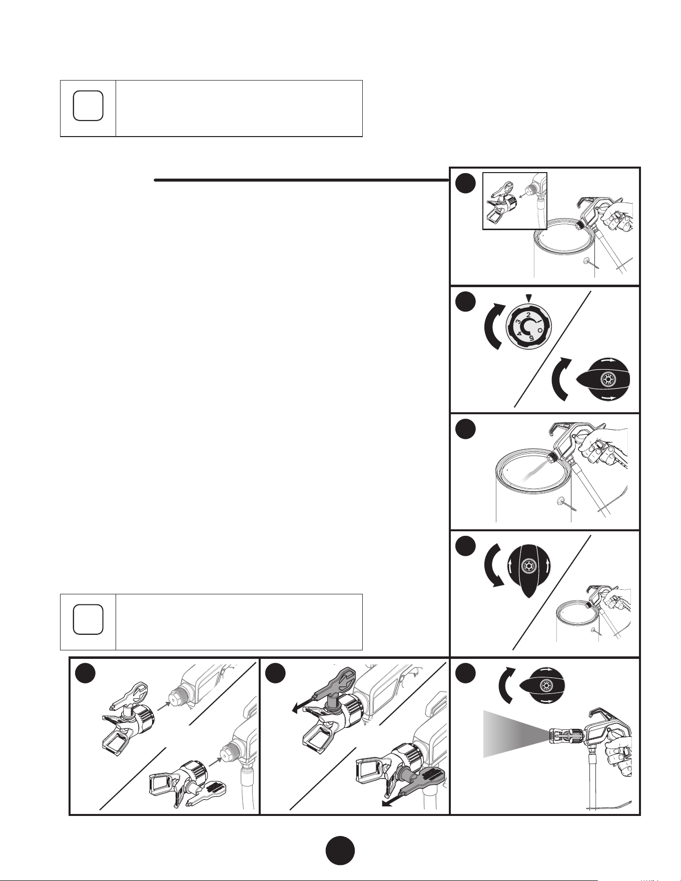
SPRAYING
i
Follow these steps to deliver spray material from
the material container to the spray gun.
YOU wILL NEED
• Waste bucket
• Scrap material / cardboard
• Drop cloths to protect oors and furnishings from overspray
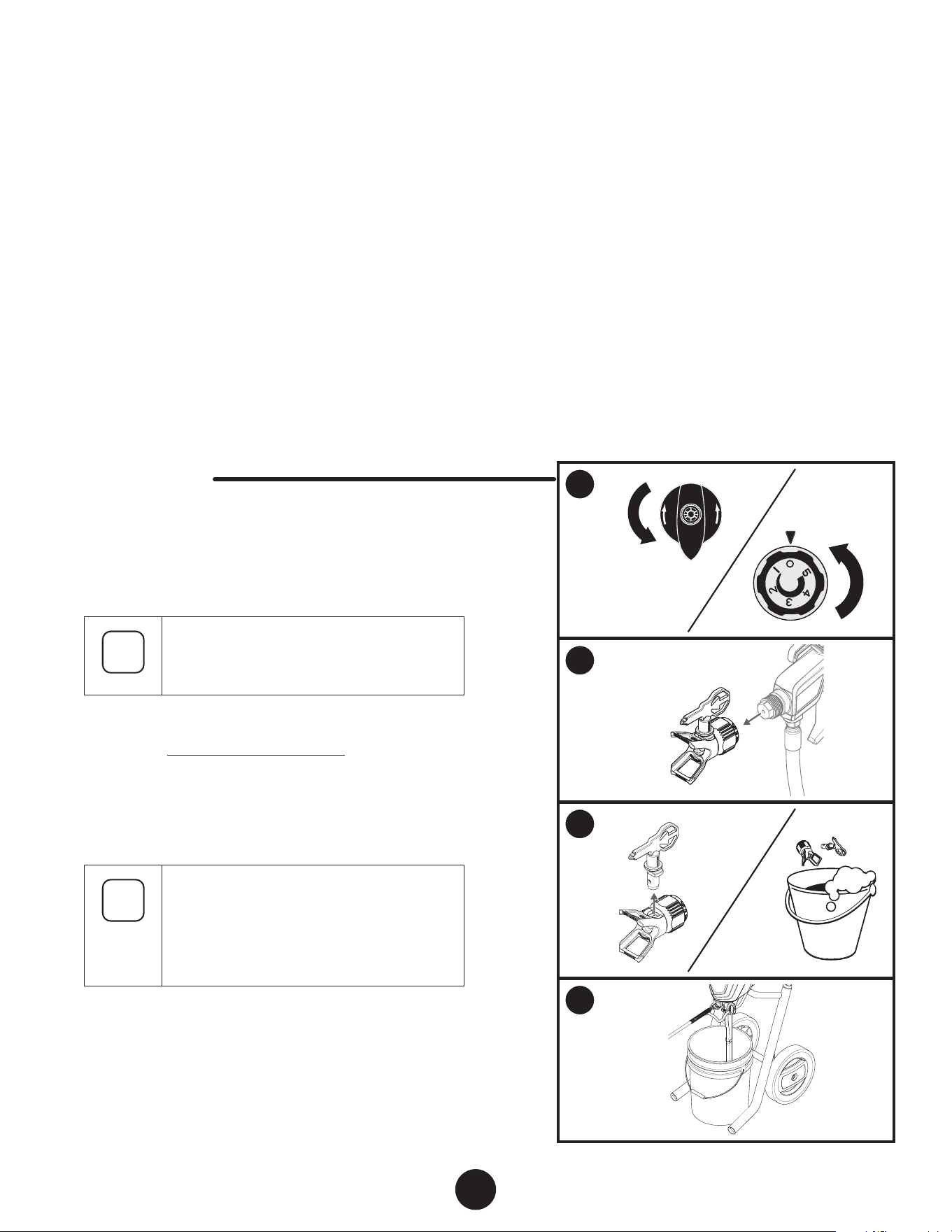
1. Make sure the tip guard is removed. Point the spray gun
into a separate waste container. Unlock the spray gun trigger.
Squeeze and hold trigger for steps 2-3.
2. Slowly turn the pressure control knob clockwise to setting ‘2’.
Turn the PRIME/SPRAY knob to SPRAY.
3. Continue to squeeze trigger until the material is owing freely
through the spray gun.
4. Perform the Pressure Relief Procedure, page 9.
5. Make sure the spray gun trigger is locked. Thread the spray
tip guard assembly onto the gun.
Tighten by hand.
6. Make sure the spray tip is rotated forward to the spray
position, with the arrow on the tip facing forward.
Unlock the spray gun trigger.
7. Slowly turn the pressure control knob clockwise to the
maximum setting (5).
Turn the PRIME/SPRAY knob to SPRAY.
Point the spray gun at a piece of scrap material/cardboard.
Pull the trigger and practice spraying (see pages 12-13).
i
Motor will cycle ON and OFF while spraying to
regulate pressure. This is normal.
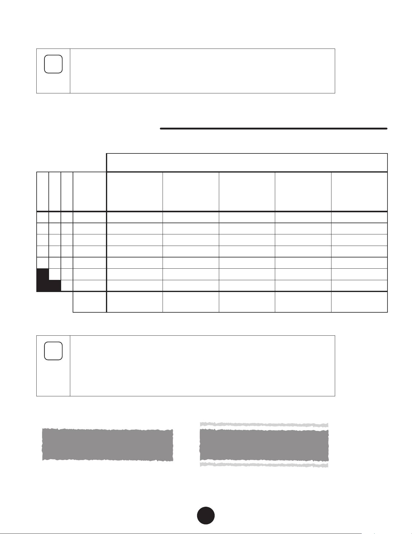
i
Prior to spraying, it is important that you are using the spray tip / spray material combination
that it suitable for your spraying job.
Refer to the chart below for a list of recommendations regarding spray tip size, spray material
and pressure settings.
CONTROLMAX TIP SELECTION ChART
COATINGS
1500
1700
1900
TIP SIzE
Interior stains
Interior and
exterior clears
Water sealers
Exterior solid
stains
Acryic sealers
Acrylics
Enamels
Polyurethanes
Latex primers
Interior latex
paints
Oil primers
Exterior latex
paints
h h h
211
h
h h h
311
h
h h h
313
h h
h h h
413
h h h
h h h
515
h h h
h h
517
h h
h
619
h
SPRAY
PRESSURE
Low - Med
(setting 1-3)
Med - High
(setting 3-5)
Med - High
(setting 3-5)
High
(setting 5)
High
(setting 5)
i
The chart above is a general guideline. Refer to coating manufacturer’s recommendations for
airless sprayer tip sizes as well as guidelines for thinning the product to be sprayed.
The graphics below show the dierence between a good spray pattern versus a spray pattern
that is poor or has “tailing”, which may be caused by the improper spray tip / spray material
/ spray pressure combination. For further causes of a poor spray problem, refer to the
Troubleshooting section.
GOOD SPRAY PATTERN POOR SPRAY PATTERN (TAILING)
12
EN
PRACTICE SPRAYING
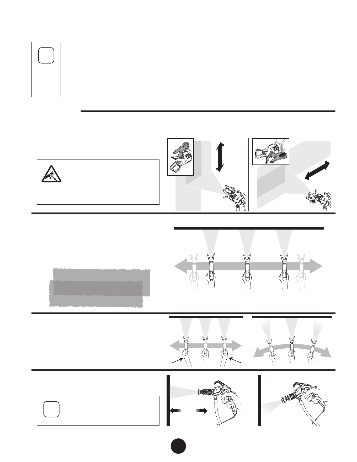
While spraying, the spray guard / tip assembly can
be rotated to better suit your spraying motion.
Lock the spray gun trigger prior
to rotating the spray guard / tip
assembly.
Make sure the spray guard nut is not
loosened after rotating.
Trigger gun after starting the stroke. Release the
trigger before ending the stroke.
The spray gun should be moving when the trigger
is pulled and released.
Overlap each stroke by about 50%. This will
ensure an even coating.
50% Overlap
Start
stroke
End
stroke
Pull
trigger
Release
trigger
Move
steadily
Flex your wrist as you move in order to keep gun
parallel to the surface.
CORRECT INCORRECT
Hold the spray gun level.
i
The distance from the spray gun to
the spray object should not exceed
18 inches.
10” - 12”
(25 - 30 cm)
CORRECT
10” - 12”
(25 - 30 cm)
INCORRECT
EN
13
PRACTICE SPRAYING
i
If the spray pattern becomes distorted or stops spraying completely while the gun is triggered,
follow any or all the procedures listed on pages 12-13.
If you plan to be away from your spray project for more than one hour, follow the Short Term
Storage instructions on page 15.
If you have diculty achieving a good spray pattern, your spray tip may not be ideal for the type
of material you are spraying. Refer to “Troubleshooting” page, 22.
YOU wILL NEED
• A surface to practice spraying (wood, carboard or scrap drywall)
1
2
3
SPRAY
PRIME
4
14
EN
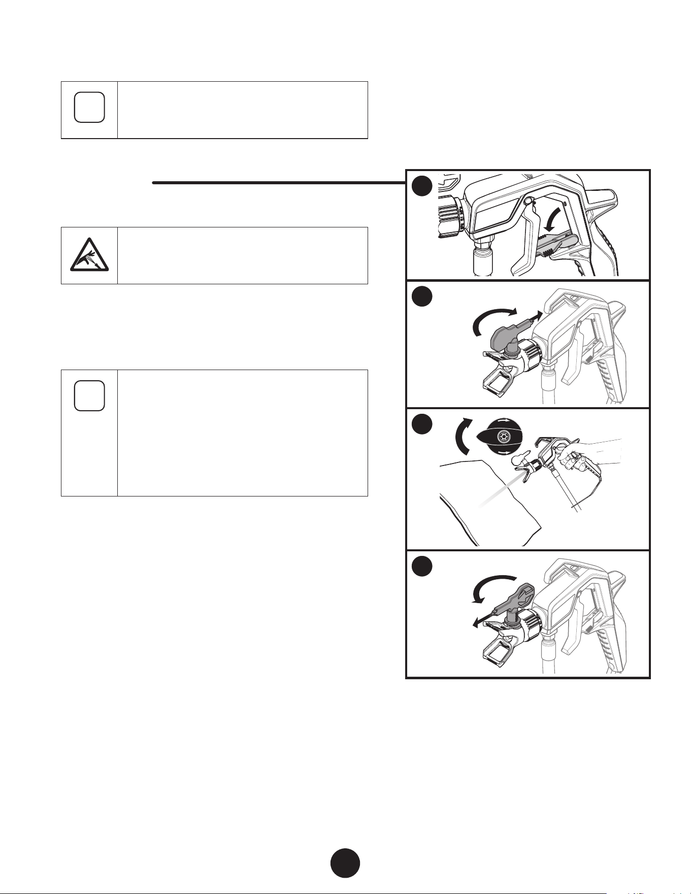
SPRAYING TROUBLEShOOTING - CLEAR ThE SPRAY TIP
i
If the spray pattern becomes distorted or stops
spraying completely while the gun is triggered, the
spray tip could be clogged. Follow the steps below.
YOU wILL NEED
• Scrap material / cardboard
Do not attempt to unclog or clean the tip with
your nger. High pressure uid can cause injection
injury.
1. Lock the spray gun.
2. Rotate spray tip 180 degrees from its current position.
i
If spray tip is dicult to rotate, relieve pressure by:
1) slowly turn PRIME/SPRAY knob to PRIME,
2) unlock the spray gun and
3) squeeze trigger while pointing at scrap material/
cardboard.
Release trigger, lock the spray gun, and try rotating
spray tip again.
3. Make sure the PRIME/SPRAY knob is turned to SPRAY.
Unlock the spray gun.
Point at a piece of scrap material / cardboard and squeeze
trigger until material comes out in a high pressure stream.
Release the trigger and lock the spray gun.
4. Rotate spray tip forward to the spray position.
Unlock the spray gun and resume spraying.
1
2
3
EN
15
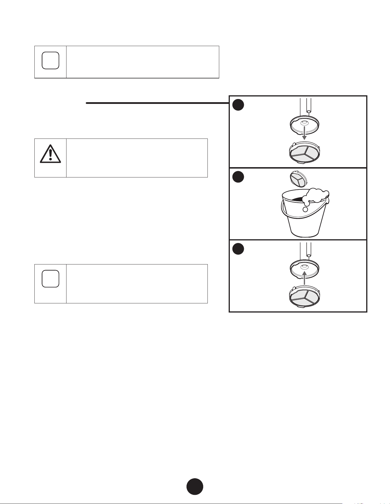
SPRAYING TROUBLEShOOTING - CLEAN ThE INLET FILTER
i
If the spray pattern becomes distorted or stops spraying
completely while the gun is triggered, the inlet lter
could be clogged. Follow the steps below.
YOU wILL NEED
• Warm, soapy water for latex material
• Mineral spirits for oil based materials
At
tention
Make sure your oors and furnishings are covered
with drop cloths to prevent accidental drips.
1. Remove the inlet lter by pulling it o the suction tube.
2. Clean the screen using the appropriate cleaning solution
(warm, soapy water for latex materials, mineral spirits for oil-
based materials).
3. Snap the inlet lter back into place.
i
If after completing all of the steps in Spraying
Troubleshooting you are still experiencing
problems spraying, refer to the Troubleshooting
section (page 22).
1
SPRAY
PRIME
2
AND
3
4
AND
5 6
PAGE 11
i
This procedure should be used when taking a short
term break or when ending your project for the day.
If your break is longer than 16 hours follow cleanup
instructions, pages 17-18.
YOU wILL NEED
• Water
• Plastic bag
• Damp rags
• Stir stick
i
Instructions are for latex materials only! If using oil
based material follow instructions for cleanup
on
pages 17-18.
ShUTDOwN
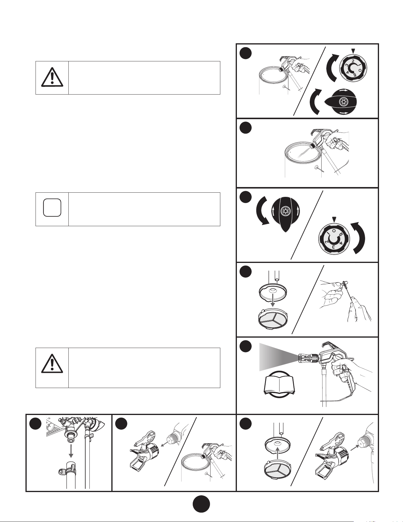
1. Perform the Pressure relief Procedure, page 9.
2. Turn spray tip 90º. This will prevent air from drying out any
spray material that may be inside the spray tip. Wrap spray
tip in a damp rag and then place entire spray gun in plastic
bag.
3. Pour 1/2 cup water slowly on the top of the paint to prevent
the paint from drying.
Place the entire spraying system out of the sun.
STARTUP
4. Remove the spray gun from the plastic bag or the water. Turn
the spray tip back to the spraying position.
5. If water was added during shut down, stir water into material
with the stir stick.
6. Follow Spraying instructions, page 11.
16
EN
ShORT-TERM STORAGE
1
SPRAY
PRIME
2
3
4
EN
17
CLEANUP
CLEANING NOTES - READ BEFORE CLEANING
• When using latex material, clean sprayer and components
with warm, soapy water. For oil based material use
mineral spirits. Never use mineral spirits with latex
materials.
• NEVER use gasoline to clean sprayer.
• Dispose of used cleaning solution properly.
• Thorough cleaning and lubrication of sprayer is
important to ensure proper operation after storage.
• If you ush your sprayer with mineral spirits, repeat
Cleanup instructions using warm, soapy water.
YOU wILL NEED
• Warm, soapy water if using latex material
• Mineral spirits if using oil-based material
• Empty waste container
• Soft-bristled brush
i
The suction tube may become discolored or
cloudy after being used. This is normal.
1. Perform Pressure relief Procedure (page 9).
2. Remove the tip guard from the spray gun.
3. Remove the spray tip from the tip guard. Place both
into a container of the appropriate cleaning solution.
i
It is okay to place the spray tip and tip guard
in the same container of cleaning solution
that you will use in the following steps.
Allowing them to soak while ushing will
make it easier to clean them afterwards.
4. Submerge suction set into a bucket with the
appropriate cleaning solution.
(Continued on the next page)
Follow these steps whenever cleaning with mineral
spirits:
• If spraying or cleaning with oil-based materials, the spray
gun must be grounded while preparing the spray hose
or cleaning.
• Ground the gun by holding it against the edge of a metal
container while purging. Failure to do so may lead to a
static electric discharge which may cause a re.
• Always ush spray gun at least one hose length from
spray pump.
• If collecting ushed solvent in one gallon metal container,
place it into an empty ve gallon container, then ush.
• Area must be free from vapors.
• Follow all cleanup instructions.
5
SPRAY
PRIME
6
7
SPRAY
PRIME
8
9
P. 11
10 11 12
18
EN
CLEANUP - CONTINUED
5. Point the spray gun at the side of a waste container.
Ground the gun against the side of a metal waste
container if ushing with mineral spirits.
While squeezing the trigger, turn the pressure control knob to
‘2’, and turn the PRIME/SPRAY knob to SPRAY.
6. Continue squeezing the trigger until uid is coming out clear.
You may need to get new cleaning solution.
7. Perform Pressure Relief Procedure, page 9.
8. Remove the inlet lter by pulling if o the suction tube. Clean
by hand using a soft-bristled brush.
Remove the tip guard and spray tip from the cleaning solution.
Clean by hand using a soft bristled brush.
i
Make sure the opening in the black housing on
the suction tube that the inlet lter attaches to is
completely clean and free from spray material.
9. iMPOrTanT STEP: Fill a bucket with warm, soapy water.
Following steps 5-7 in the “Spraying” section, spray at least one
gallon of warm, soapy water. This will ensure that the spray tip
will be completely clean for the next use.
10. Perform Pressure Relief Procedure, page 9. Remove the suction
tube. Run water from a faucet through the tube to ush out any
remaining material. Do not reinstall the suction tube.
11. Remove the spray tip assembly.
Repeat step 5 from above, continuing to squeeze the trigger
until no uid comes from the gun (this will purge any remaining
water in the spray hose).
Turn PRIME/SPRAY knob to PRIME. Turn power OFF.
At
tention
Do not allow the pump to run for more than one
minute without uid.
12. Reattach both the inlet lter and spray tip/tip guard assembly.
1
HOUSEHOLD
OIL
2
3
a
HOUSEHOLD
OIL
4
5
EN
19
LONG TERM STORAGE
i
Follow these steps to prepare your sprayer for long-
term storage.
YOU wILL NEED
• Light household oil / Piston Lube
• Rags
• Two adjustable wrenches
i
The suction tube should still be removed from the
end of the previous section and the PRIME/SPRAY
knob should be in the PRIME position.
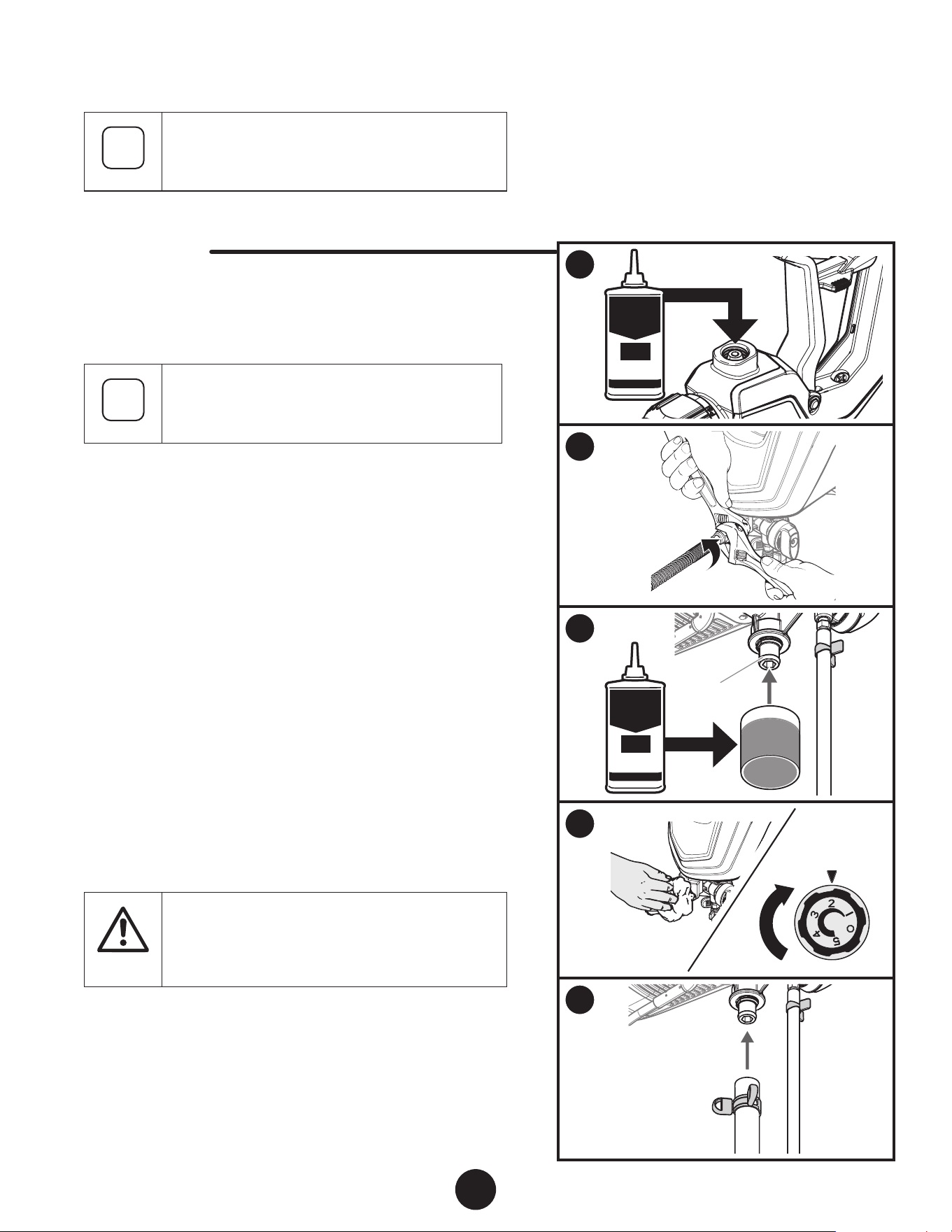
1. Remove the spray hose from the spray gun. Tip the spray gun
upside down and pour a few drops of Piston Lube inside the
gun housing.
A light oil can be substituted (such as 10W30 motor oil or
vegetable oil for example).
2. Place a wrench on the outlet valve to secure it. Using the
second wrench, remove the spray hose.
3. Fill a cup or other container with two ounces of Piston Lube
and submerge the inlet valve (a) into the oil.
A light oil can be substituted (such as 10W30 motor oil or
vegetable oil for example).
4. Cover the outlet valve with a rag. Turn the pressure control
knob to ‘2’ and let the pump run for ve seconds.
Turn power OFF.
5. Replace suction tube. Wipe entire unit, hose, and spray gun
to remove accumulated spray material.
At
tention
Store the unit indoors with the power cord wrapped
around the cart handle or stand.
1
2
a
b
d
e
c
3
b
c
4
20
EN
CLEANING ThE INLET vALvE
i
Cleaning or replacing the inlet valve may be required if the unit has
priming problems. Priming problems may be prevented by properly
cleaning the sprayer and following the long-term storage steps.
YOU wILL NEED
• Adjustable wrench or 10 mm allen wrench
• Warm, soapy water if using latex material
• Mineral spirits for oil based material
• Petroleum jelly
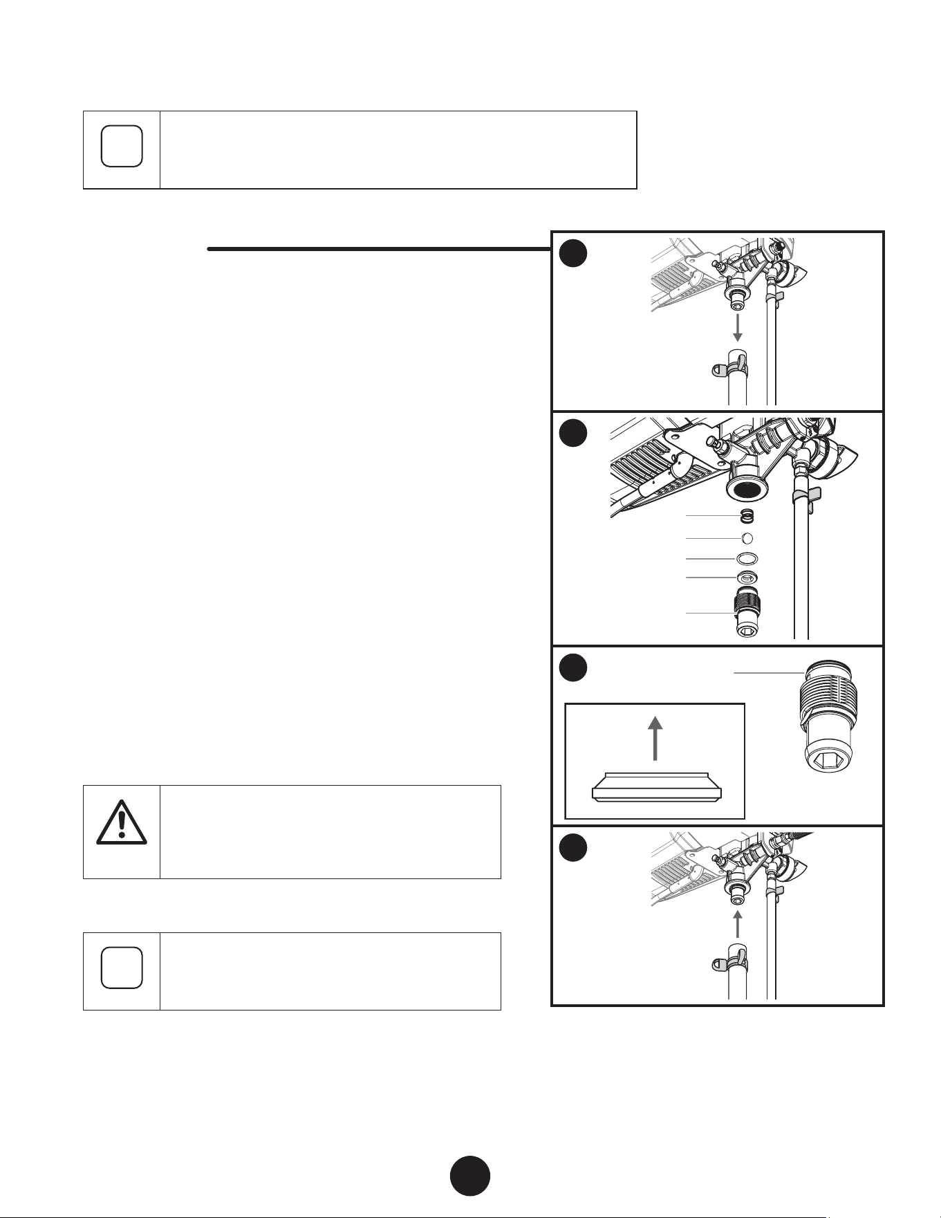
1. Remove the suction tube.
2. Place a wrench on the ats of the inlet valve tting (a), or
insert a 10 mm allen wrench into the hex opening. Unscrew
the inlet valve tting from the sprayer. Remove the inlet valve
seat (b), O-ring (c) inlet valve ball (d) and spring (e). Take care
not to lose any removed parts.
Visually inspect the removed parts, as well as the inside
and outside of the inlet valve tting. Inspect the inlet valve
housing area where the inlet valve assembly was removed.
Clean any paint residue in these places with the appropriate
cleaning solution.
3. Lubricate the O-ring (c) on the inlet valve with petroleum jelly.
Replace all parts back into the inlet valve housing in the
reverse order of how they were removed. Note the correct
orientation of the inlet valve seat (b). Replace inlet valve
assembly by screwing it into the sprayer. Tighten with a
wrench.
At
tention
Do not overtighten the inlet valve tting (torque to
120-150 in.-lbs).
4. Replace suction tube.
i
If priming problems persist, you may need to replace
the inlet valve assembly. Call Technical Service (1-
866-848-2698) to order a new inlet valve assembly.
1
2
3
4
5
EN
21
CLEANING ThE OUTLET vALvE
i
Cleaning or replacing the outlet valve may be necessary if spray performance
remains poor after following the steps in the Troubleshooting section. Call
Technical Service (1-866-848-2698) to order a new outlet valve assembly.
YOU wILL NEED
• Two 6” adjustable wrenches
• 2.5 mm allen wrench
• Warm, soapy water if using latex material
• Mineral spirits for oil based material
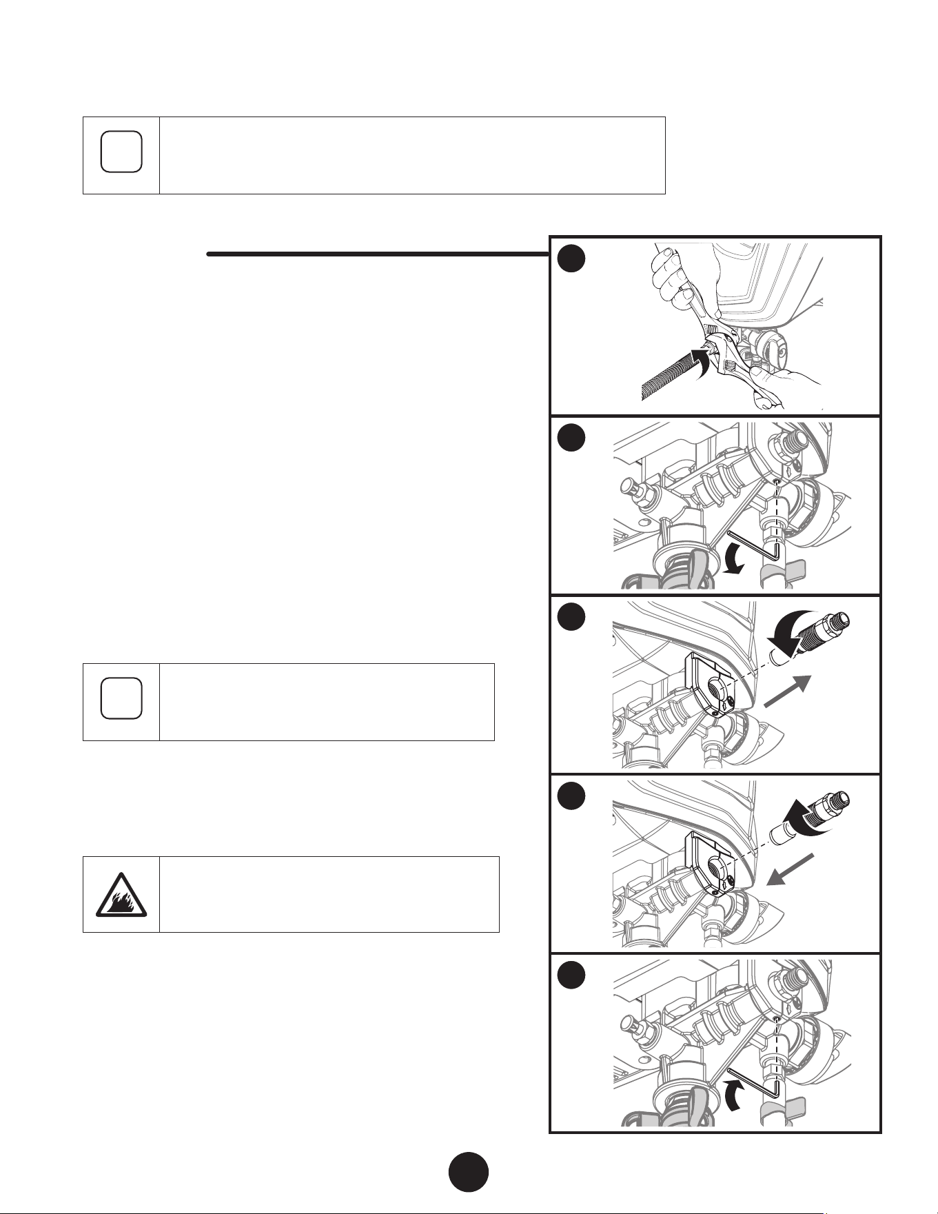
1. Place a wrench on the outlet valve to secure it. Using the
second wrench, remove the spray hose.
2. Loosen (but do not remove) the set screw just underneath
the outlet valve with a 2.5 mm allen wrench.
3. Unscrew outlet valve from outlet valve housing using wrench.
Remove any accumulated material inside outlet valve housing
using appropriate solution for material being used.
Pay particular attention to the ball and seat area at the end
of the outlet valve (opposite the hose end). Remove any
accumulated material.
i
Recommendation: If used with latex-based paints,
ush out the outlet valve with water from a faucet.
4. Replace with new or cleaned outlet valve and tighten with
wrench. Do not over tighten. Torque to 90-110 in-lbs.
5. Tighten the set screw to secure the outet valve. Do not over
tighten. Torque to 20-25 in-lbs.
It is very important to tighten the set screw to
ensure proper grounding of the hose and gun

22
EN
TROUBLEShOOTING
PROBLEM CAUSE SOLUTION
A. The sprayer does not turn on. 1. The sprayer is not plugged in.
2. Pressure control knob is set to OFF.
3. The sprayer shuts o while under pressure.
4. No power is coming from power outlet.
5. The extension cord is damaged or is not the
proper gauge or length.
6. There is a problem with sprayer motor.
7. Spray tip clogged.
1. Plug the sprayer in.
2. Turn pressure control knob to recommended
setting.
3. Motor will cycle ON and OFF while spraying to
regulate pressure. This is normal.
4. Reset circuit breaker or nd another outlet.
5. Refer to General Information.
6. Call Technical Service (1-866-848-2698).
7. Refer to Clear the Spray Tip.
B. The sprayer starts but does not
draw material when the PRIME/
SPRAY knob is set to PRIME
1. The inlet valve is stuck from old material.
2. There is no suction at the inlet valve.
3. The suction tube is not properly installed.
4. The suction tube is damaged or completely
clogged.
5. The inlet lter is clogged.
6. The outlet valve is stuck or contains debris.
7. The inlet valve or outlet valve is worn or
damaged.
8. The PRIME/SPRAY valve is plugged.
1. Push pusher stem to release. If still stuck refer to
Cleaning the Inlet Valve.
2. Remove suction tube and check suction by
placing nger on bottom of inlet valve. If no
suction, refer to Cleaning the Inlet Valve.
3. Reinstall the suction tube
4. Replace with a new suction tube.
5. Refer to Clean the Inlet lter or replace the inlet
lter.
6. Refer to Cleaning the Outlet Valve.
7. Replace the inlet valve or outlet valve.
8. Call Technical Service (1-866-848-2698).
C. The sprayer draws up material
but the pressure drops when
the gun is triggered (bad spray
pattern or no spray pattern)
1. Pressure too low.
2. The spray tip is worn.
3. The inlet lter is clogged.
4. The spray tip is plugged.
5. The material is too heavy or thick.
6. The material is too coarse.
7. The outlet valve assembly is damaged or worn.
8. Spray hose is too long.
9. Filter accessory is dirty or plugged.
1. Increase the pressure by turning the pressure
control knob to a higher setting.
2. Replace spray tip with a new one.
3. Refer to Clean the Inlet lter, or replace with a
new inlet lter.
4. Refer to Clear the Spray Tip or replace with a
new spray tip.
5. Thin the material, or use a larger tip (see Tip
Selection Chart, page 12).
6. Strain the material or purchase the lter
accessory (see Accessories, page 72).
7. Replace the outlet valve.
8. Remove any extra hose length that has been
added.
9. Clean or replace.
D. The PRIME/SPRAY knob is set to
SPRAY and there is ow through
the material return tube
1. The PRIME/SPRAY valve is dirty or worn. 1. Call Technical Service (1-866-848-2698).
E. The spray gun leaks 1. Internal parts of spray gun are worn or dirty. 1. Call Technical Service (1-866-848-2698).
F. The spray tip assembly leaks 1. The tip guard nut is loose.
2. Tip guard was assembled incorrectly.
3. Tip seal is worn
1. Tighten tip guard nut.
2. Remove and assemble correctly.
3. Replace tip seal
G. The spray gun will not spray 1. The spray tip plugged.
2. The spray tip is in wrong position.
3. PRIME/SPRAY knob not set on SPRAY.
4. Filter accessory is dirty or plugged.
1. Refer to Clear the Spray Tip .
2. Rotate spray tip to SPRAY position.
3. Turn PRIME/SPRAY knob to SPRAY.
4. Clean or replace.
H. The spray pattern is poor (tailing) 1. Pressure too low.
2. The spray tip is plugged.
3. The inlet lter is clogged.
4. The spray tip is worn.
5. The material is too heavy or thick.
6. Spray hose is too long.
1. Increase the pressure by turning the pressure
control knob to a higher setting.
2. Refer to Clear the Spray Tip
3. Refer to Clean the Inlet lter or replace with a
new inlet lter.
4. Replace the spray tip.
5. Thin material per manufacturer’s
recommendations.
6. Remove any extra hose length that has been
added.
I. The spray tip will not turn 1. High pressure has locked the spray tip in place. 1. Refer to Clear the Spray Tip.

EN
23
wARRANTY
AIRLESS PAINT SPRAY EQUIPMENT
This product, manufactured by Titan Tool, is warranted to the original retail purchaser against defects in material and workmanship
for two years from date of purchase.
This warranty does not cover damage resulting from improper use, accidents, user’s negligence or normal wear. This warranty does
not cover any defects or damages caused by service or repair performed by anyone other than a Titan Authorized Service Center.
This warranty does not apply to accessories.
TITAN SHALL NOT IN ANY EVENT BE LIABLE FOR ANY INCIDENTAL OR CONSEQUENTIAL DAMAGES OF ANY KIND, WHETHER FROM
BREACH OF THIS WARRANTY OR ANY OTHER REASON.
If any product is defective in material and/or workmanship during the applicable warranty period, please call Titan Technical
Service at 1-866-848-2698. DO nOT rETurn THE PrODucT TO THE OriginaL rETaiLEr. Under Titan’s Free Tool Replacement
Program, Titan Technical Service will either replace the defective part, or refer you to your nearest Authorized Service Center for
repair.
SOME STATES DO NOT ALLOW LIMITATIONS ON HOW LONG AN IMPLIED WARRANTY LASTS OR THE EXCLUSION OF INCIDENTAL OR
CONSEQUENTIAL DAMAGES, SO THE ABOVE LIMITATION AND EXCLUSION MAY NOT APPLY TO YOU.
THiS warranTy giVES yOu SPEciFic LEgaL rigHTS, anD yOu May aLSO HaVE OTHEr rigHTS wHicH Vary FrOM STaTE
TO STaTE.
United States Sales & Service
1770 Fernbrook Lane
Minneapolis, MN 55447
www.titantool.com
Phone:
Fax:
1-866-848-2698
1-763-519-3563
1770 Fernbrook Lane
Minneapolis, MN 55447
www.titantool-international.com
Fax: 1-763-519-3509
International
international@titantool.com
DATE CODE LOCATION (ALL UNITS)
68
EN F ES
Parts List • Liste de Pièces • Lista de Piezas
#
1500 1700 Description Description Descripción
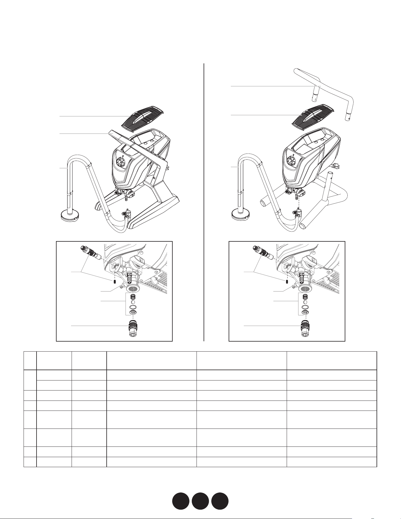
1 0580389 ---------
Base assembly
Ensemble de la base
Conjunto de la base
--------- 0580163
Handle assembly
Ensemble de la poignée
Conjunto de la manilla
2 0580041B 0580041B Door (single piece) Porte (pièce unique) Tapa (pieza única)
3* --------- --------- Suction set assembly Ensemble d'aspiration Conjunto de succión
4 0580072A 0580072A Outlet valve assembly Ensemble de la soupape de
sortie
Conjunto de la válvula de
salida
5 0580071A 0580071A Inlet valve tting (includes
O-ring)
Raccord de la soupape
d'entrée (inclut le joint torique)
Conexión de la válvula de
entrada (incluye junta tórica)
6 0580391 0580391 Inlet valve kit Trousse de la soupape d'entrée Kit de válvula de entrada
7 9885553 9885553 Return tube tting Raccord de tube de retour Conexión de tubo de retorno
* Seeseparatelisting•Voirlalisteséparée•Consultelalistaseparada
Main asseMbLy (stand ModeLs) • enseMbLe PrinciPaL (ModèLes de suPPort) • Montaje PrinciPaL (ModeLos de soPorte)
1500 1700
1
2
4
5
6
3
1
2
3
4
5
6
7 7
69
Parts List • Liste de Pièces • Lista de Piezas
ES F EN
#
1700 Pro 1900 Pro Description Description Descripción
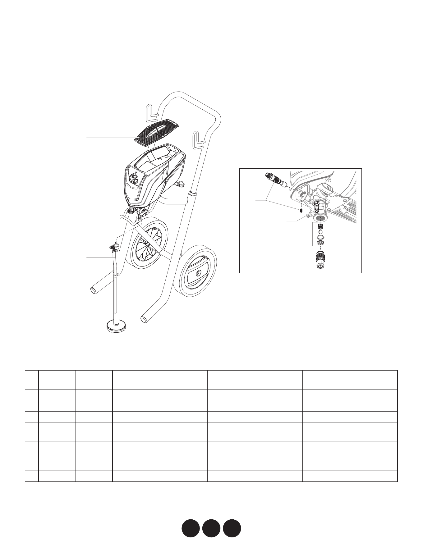
1 0580390 0580390
Handle assembly
Ensemble de la poignée
Conjunto de la manilla
2 0580041B 0580041B Door (single piece) Porte (pièce unique) Tapa (pieza única)
3* --------- --------- Suction set assembly Ensemble d'aspiration Conjunto de succión
4 0580072A 0580072A Outlet valve assembly Ensemble de la soupape de
sortie
Conjunto de la válvula de
salida
5 0580071A 0580071A Inlet valve tting (includes
O-ring)
Raccord de la soupape
d'entrée (inclut le joint torique)
Conexión de la válvula de
entrada (incluye junta tórica)
6 0580391 0580391 Inlet valve kit Trousse de la soupape d'entrée Kit de válvula de entrada
7 9885553 9885553 Return tube tting Raccord de tube de retour Conector de tubo de retorno
* Seeseparatelisting•Voirlalisteséparée•Consultelalistaseparada
Main asseMbLy (cart ModeLs) • enseMbLe PrinciPaL (ModèLes de chariot) • Montaje PrinciPaL (ModeLos de carro)
1700 Pro / 1900 Pro
1
2
3
4
5
6
7
replacement parts available by calling
customer service
On peut obtenir des pièces de rechange en
appelant le Service à la clientèle.
Los repuestos están disponibles llamanado al
servicio a clientes.
1-866-848-2698
70
EN F ES
Parts List • Liste de Pièces • Lista de Piezas
#
1500 1700
1700 Pro
1900 Pro Description Description Descripción
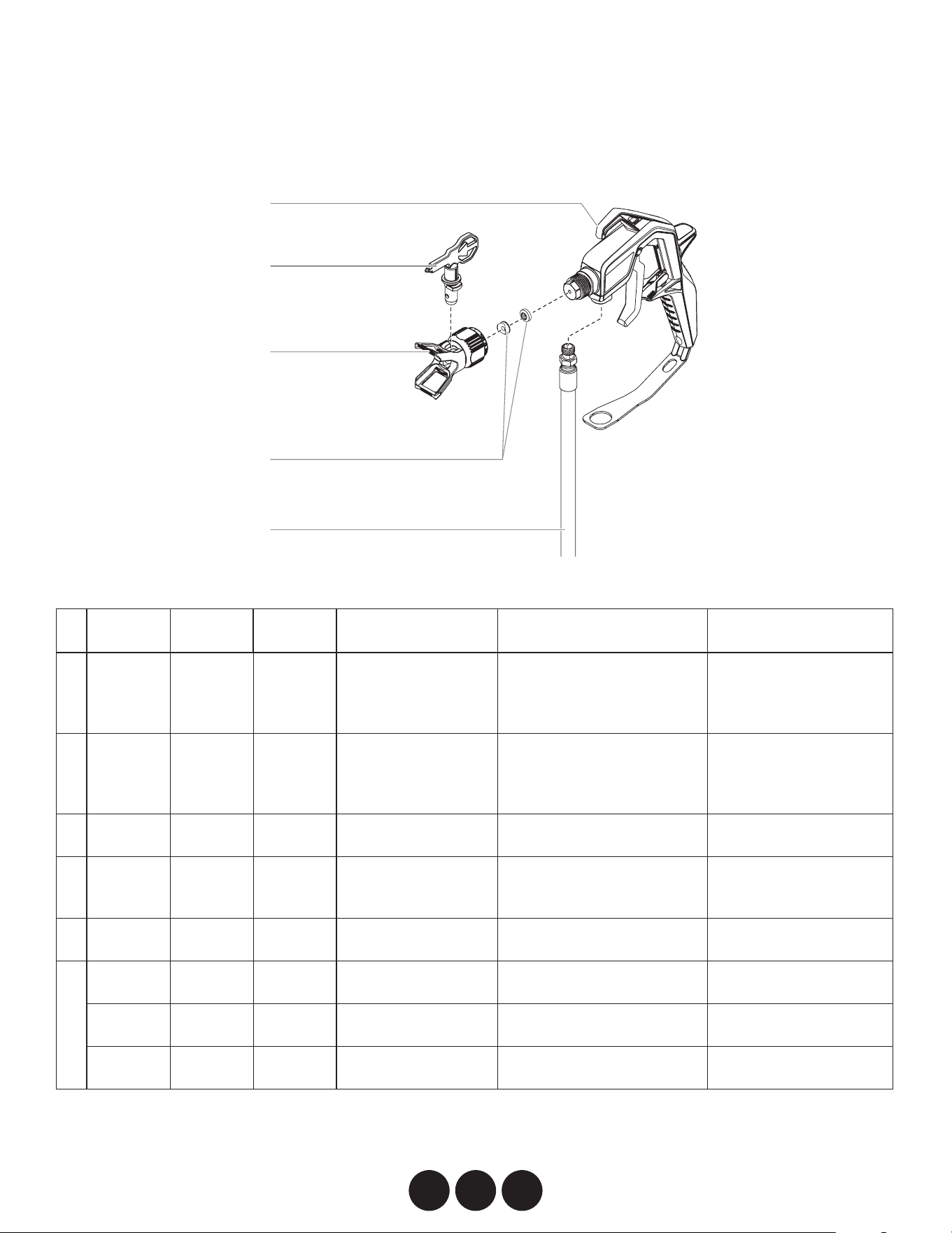
1 353-700 ------- -------
Spray gun assembly,
ControlMax (includes
item 2-4)
Ensemble du pistolet de
pulvérisation, ControlMax
(inclut les articles 2 à 4)
Conjunto de la pistola
pulverizadora, ControlMax
(incluye los elementos 2
a 4)
------- 353-701 353-701
Spray gun assembly,
ControlMax Pro
(includes item 2-4)
Ensemble du pistolet de
pulvérisation, ControlMax Pro
(inclut les articles 2 à 4)
Conjunto de la pistola
pulverizadora, ControlMax
Pro (incluye los elementos
2 a 4)
2 353-515 353-515 353-515 Spray tip, 515 Embout, 515 Boquilla de pulverización,
515
3 353-702 353-702 353-702 Spray guard assembly
(includes item 4)
Ensemble anti-éclaboussure
(inclut le article 4)
Conjunto de la protección
de pulverización (incluye
le elemento 4)
4 342-100 342-100 342-100 Tip seal kit Trousse de joint de l'embout Juego de junta de la
boquilla
5 353-706 ------- ------- Spray hose (25’) Tuyau de pulvérisation (7 m) Manguera de
pulverización (7 m)
------- 353-707 ------- Spray hose (30’) Tuyau de pulvérisation (9 m) Manguera de
pulverización (9 m)
------- ------- 353-708 Spray hose (50’) Tuyau de pulvérisation (15 m) Manguera de
pulverización (15 m)
sPray gun asseMbLy • PistoLet de PuLvérisation • PistoLa de rociadora
1
4
2
3
5
71
Parts List • Liste de Pièces • Lista de Piezas
ES F EN
#
1500 1700
1700 Pro
1900 Pro Description Description Descripción
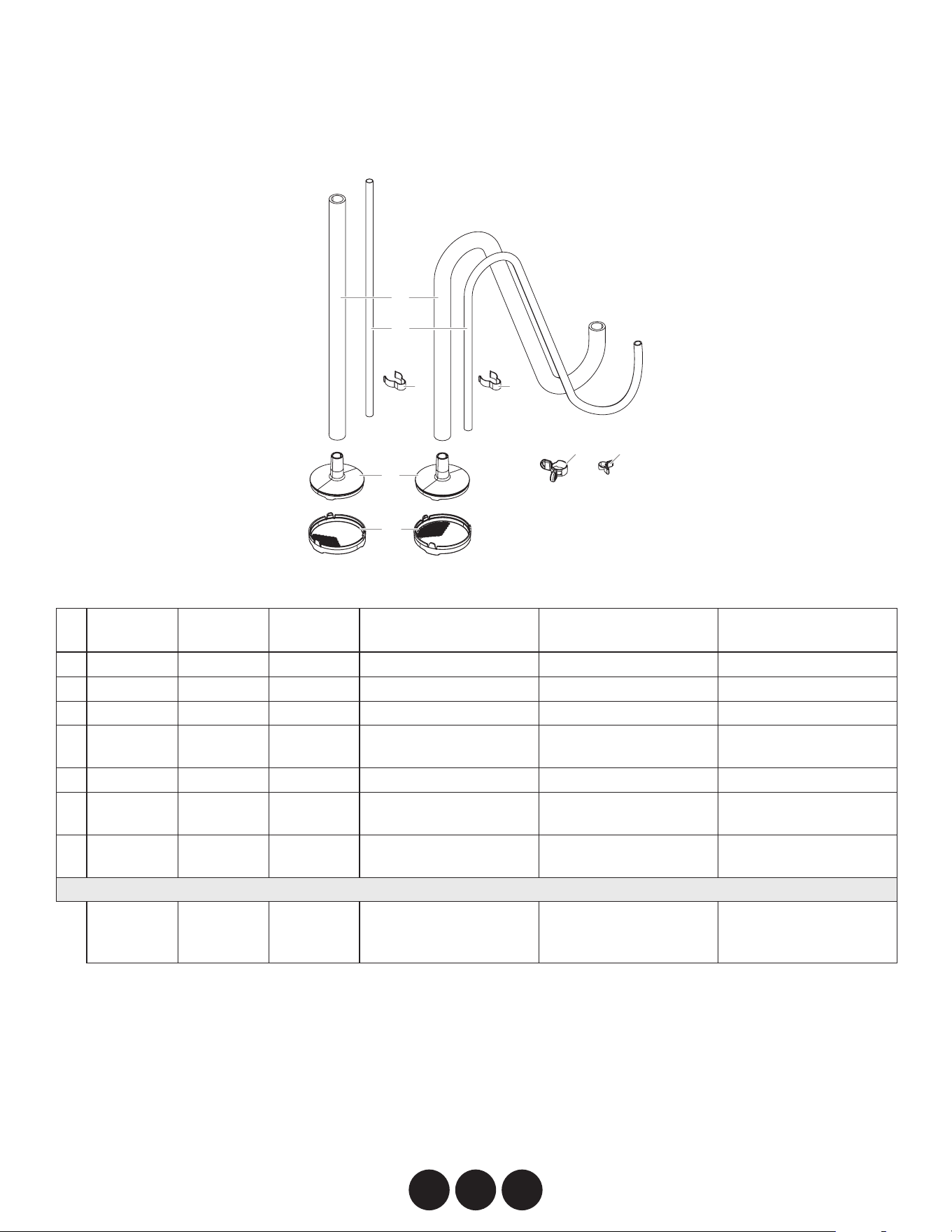
1 ------- ------- -------
Suction tube
Tube d’aspiration Tubo de
succión
2 0580487 0580487 0580208 Return tube Tuyau de retour Tubo de retorno
3 0512390 0512390 0512390 Clip (single piece) Agrafe (pièce unique) Sujetador (pieza única)
4 0580154 0580154 0580154 Inlet lter housing Boîtier du ltre d'entrée Carcasa del ltro de
entrada
5 0580155 0580155 0580155 Inlet lter Filtre d'entrée Filtro de entrada
6 9890222 9890222 9890222 Suction tube clamp Agrafe du tube
d'aspiration
Abrazadera del tubo de
succión
7 0327226 0327226 0327226 Return tube clip Agrafe du tube de retour Sujetador del tubo de
retorno
0580159A 0580159A 0580206A
Suction tube assembly
(includes items 1-7)
Ensemble du tube
d'aspiration (inclut les
articles 1 à 7)
Conjunto del tubo de
succión (incluye los
elementos 1 a 7)
suction set asseMbLy • enseMbLe d’asPiration • conjunto de succiÓn
1
2
5
4
3 3
6 7

72
accessories• accessoires • accesorios
PART NO. DESCRIPTION DESCRIPTION DESCRIPCIóN
SPRAY GUNS PISTOLETS DE PULvéRISATION PISTOLAS DE PULvERIzACIóN
353-700 ControlMax spray gun Pistolet de pulvérisation ControlMax Pistola de pulverización de ControlMax
353-701 ControlMax Pro spray gun Pistolet de pulvérisation ControlMax Pro Pistola de pulverización de ControlMax Pro
SPRAY TIPS AND ACCESSORIES EMBOUTS DE PULvéRISATION ET ACCESSOIRES BOQUILLA DE ROCIADO Y ACCESORIOS
353-211 211 ControlMax Tip Embout de ControlMax 211 Boquilla de ControlMax 211
353-311 311 ControlMax Tip Embout de ControlMax 311 Boquilla de ControlMax 311
353-313 313 ControlMax Tip Embout de ControlMax 313 Boquilla de ControlMax 313
353-413 413 ControlMax Tip Embout de ControlMax 413 Boquilla de ControlMax 413
353-515 515 ControlMax Tip Embout de ControlMax 515 Boquilla de ControlMax 515
353-517 517 ControlMax Tip Embout de ControlMax 517 Boquilla de ControlMax 517
353-619 619 ControlMax Tip Embout de ControlMax 619 Boquilla de ControlMax 619
353-702 ControlMax Tip Guard Protège-embout ControlMax Protección de la boquilla ControlMax
MISC. ACCESSORIES ACCESSOIRES DIvERS ACCESORIOS vARIOS
353-705 ControlMax lter/swivel Combo Combinaison ltre/pivot ControlMax Combinación de ltro y dispositivo
giratorio ControlMax
651-071 ControlMax 12" Tip Extension Rallonge d'embout ControlMax de 30 cm Extensión de la boquilla de 30 cm
ControlMax
651-072 ControlMax 24" Tip Extension Rallonge d'embout ControlMax de 61 cm Extensión de la boquilla de 61 cm
ControlMax
0516751 Tip Seal Kit Trousse du joint de l'embout Conjunto de la junta de la boquilla
314-482 Liquid Shield 1 Quart Liquid Shield 1 l Liquid Shield 1 l
314-480 Piston Lube (8 oz) Piston Lube (236 ml) Piston Lube (236 ml)
353-706 ControlMax Spray hose (25’) Tuyau de pulvérisation (7 m) ControlMax Manguera de pulverización (7 m)
ControlMax
353-708 ControlMax Spray hose (50’) Tuyau de pulvérisation (15 m) ControlMax Manguera de pulverización (15 m)
ControlMax