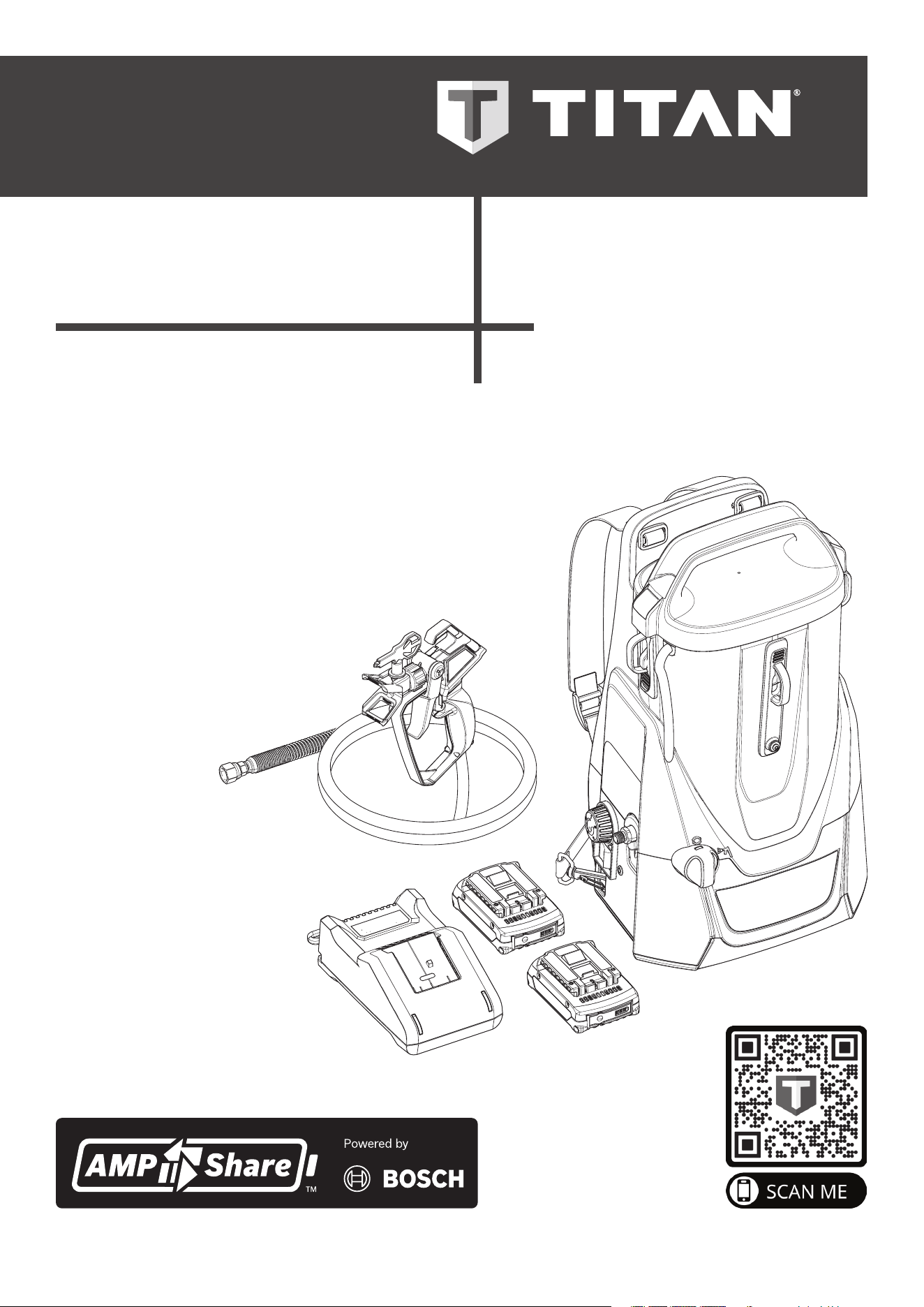
OPERATION MANUAL
ControlMax
™
1650
18V
- EN - OPERATION MANUAL 2
- F - MODE D’EMPLOI 24
- ES - INSTRUCCIONES DE USO 46
0224 • Form No. 2453108F
Model: 2441251
HIGH EFFICIENCY AIRLESS (HEA)
SPRAYING UNIT
GROUPE DE PROJECTION À HAUTE
EFFICACITÉ PRESSION (HEA)
EQUIPO DE ALTA EFICIENCIA
PRESIÓN PARA PULVERIZAR (HEA)
Scan the QR code for videos,
tips, troubleshooting, and
more.
Scannez le code QR pour
vidéos, aux conseils, au
dépannage et plus encore.
Escanee el código QR para
videos, consejos, resolución
de problemas y más.
READ THIS MANUAL FOR
COMPLETE INSTRUCTIONS
LIRE CE MANUEL POUR OBTENIR
DES DIRECTIVES COMPLÈTES
LEA ESTE MANUAL PARA OBTENER
LAS INSTRUCCIONES COMPLETAS
2
IMPORTANT SAFETY INFORMATION
ControlMax 1650
TABLE OF CONTENTS
IMPORTANT SAFETY INFORMATION ___________________ 2-6
Grounding instructions ________________________________ 2
Explanation of Symbols ________________________________ 2
Safety Hazards _____________________________________ 3-6
GENERAL INFORMATION _______________________________ 7
Specications ________________________________________ 7
PARTS AND COMPONENTS ___________________________ 8-9
Assembly ___________________________________________ 9
BEFORE YOU BEGIN ___________________________________ 10
Locking the Spray Gun ________________________________ 10
Pressure Relief Procedure _____________________________ 10
Moving / Emptying the Sprayer _________________________ 10
LOAD MATERIAL _____________________________________ 11
SPRAYING ___________________________________________ 12
PRACTICE SPRAYING _________________________________ 13
SPRAYING TROUBLESHOOTING _____________________ 14-15
Unclogging the Spray Tip _____________________________ 14
Unclogging the Spray Gun Filter ________________________ 14
Clean the Inlet Filter __________________________________ 15
SHORT TERM STORAGE _______________________________ 16
CLEANUP _________________________________________ 17-18
LONG TERM STORAGE ________________________________ 19
MAINTENANCE ____________________________________ 20-21
Cleaning the Inlet Valve _______________________________ 20
Cleaning the Outlet Valve _____________________________ 21
TROUBLESHOOTING __________________________________ 22
WARRANTY __________________________________________ 23
PARTS LIST _______________________________________ 68-69
ACCESSORIES ________________________________________ 70
EXPLANATION OF SYMBOLS
Read all safety information before operating the equipment. Save
these instructions.
To reduce the risks of re or explosion, electrical shock and the
injury to persons, read and understand all instructions included in
this manual. Be familiar with the controls and proper usage of the
equipment.
This symbol indicates a potential hazard
that may cause serious injury or loss of life.
Important safety information will follow.
At
tention
This symbol indicates a potential hazard to you
or to the equipment. Important information
that tells how to prevent damage to the
equipment or how to avoid causes of minor
injuries will follow.
Danger of skin injection
Danger of re from solvent and paint fumes
Danger of explosion from solvent, paint fumes
and incompatible materials
Danger of injury from inhalation of harmful
vapors
Electric shock hazard
i
Notes give important information which
should be given special attention.
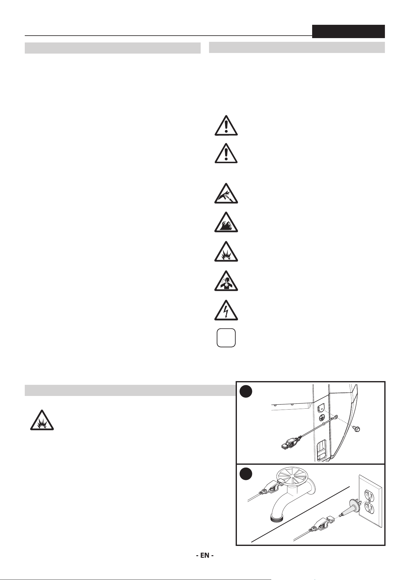
GROUNDING INSTRUCTIONS
When spraying combustable or non-water-
based materials, the sprayer must be grounded.
The sprayer includes two dierent types of
grounding wires. Follow the steps below to
properly ground the sprayer.
1. Remove the ground screw located at the rear of the unit above
the left size clip. Use the ground screw to attach the grounding
wire (with the clip attached) to the unit.
2. When ready to spray,
A. Attach the clip to an outdoor pipe xture, or
B. Plug the molded outlet plug into a grounded outlet/grounded
extension cord and then attach the clip to the metal end of the
molded plug.
1
2
A
B
3
IMPORTANT SAFETY INFORMATION
ControlMax 1650
SAFETY HAZARDS
WARNING: INJECTION INJURY
A high pressure paint stream produced by this
equipment can pierce the skin and underlying
tissues, leading to serious injury and possible
amputation. See a physician immediately.
PREVENTION:
• Do not aim the gun at, or spray any person or animal.
• Keep hands and other body parts away from the discharge. For
example, do not try to stop leaks with any part of the body.
• NEVER put your hand in front of the gun. Gloves will not provide
protection against an injection injury.
• ALWAYS keep the tip guard in place while spraying. The tip
guard provides some protection but is mainly a warning device.
• Only use a nozzle tip specied by the manufacturer.
• Use caution when cleaning and changing nozzle tips. In the case
where the nozzle tip clogs while spraying, ALWAYS lock gun
trigger, shut pump o, and release all pressure before servicing,
cleaning tip or guard, or changing tip. Pressure will not be
released by turning o the motor. The PRIME/SPRAY valve
or pressure bleed valve must be turned to their appropriate
positions to relieve system pressure. Refer to PRESSURE RELIEF
PROCEDURE described in the pump manual (page 10).
• Do not leave the unit energized or under pressure while
unattended. When the unit is not in use, turn o the unit and
relieve the pressure in accordance with the manufacturer’s
instructions.
• High-pressure spray is able to inject toxins into the body and
cause serious bodily injury. In the event that injection occurs,
seek medical attention immediately.
• Check hoses and parts for signs of damage, a leak can inject
material into the skin. Inspect hose before each use. Replace any
damaged hoses or parts. Only use Titan original-high-pressure
hoses in order to ensure functionality, safety and durability.
• This system is capable of producing 1600 PSI / 11.1 MPa. Only
use replacement parts or accessories that are specied by the
manufacturer and that are rated a minimum of 1600 PSI. This
includes spray tips, nozzle guards, guns, extensions, ttings, and
hose.
• Always engage the trigger lock when not spraying. Verify the
trigger lock is functioning properly.
• Verify that all connections are secure before operating the unit.
• Know how to stop the unit and bleed pressure quickly. Be
thoroughly familiar with the controls. Pressure will not be released
by turning o the motor. The PRIME/SPRAY valve or pressure
bleed valve must be turned to their appropriate positions to
relieve system pressure. Refer to PRESSURE RELIEF PROCEDURE
described in the pump manual (page 10).
• Always remove the spray tip before ushing or cleaning the
system.
i
NOTE TO PHYSICIAN: Injection into the skin is
a traumatic injury which can lead to possible
amputation. It is important to treat the injury
as soon as possible. DO NOT delay treatment
to research toxicity. Toxicity is a concern with
some coatings injected directly into the blood
stream. Consultation with a plastic surgeon or
reconstructive hand surgeon may be advisable.
WARNING: ELECTRIC SHOCK
This product can cause injury due to electric shock.
PREVENTION:
• Avoid body contact with earthed or grounded surfaces, such as
pipes, radiators, ranges and refrigerators. There is an increased
risk of electric shock if your body is earthed or grounded.
• Do not expose power tools to rain or wet conditions. Water
entering a power tool will increase the risk of electric shock.
WARNING: EXPLOSION OR FIRE
Solvent and paint fumes can explode or ignite.
Severe injury and/or property damage can occur.
PREVENTION:
• Do not spray ammable or combustible materials near an
open ame, pilot lights or sources of ignition such as hot
objects, cigarettes, motors, electrical equipment and electrical
appliances. Avoid creating sparks from connecting and
disconnecting power cords.
• Do not spray or clean with liquids having a ash point of less
than 38˚C (100˚F). Flash point is the temperature at which a uid
can produce enough vapor to ignite.
• Paint or solvent owing through the equipment is able to result
in static electricity. Static electricity creates a risk of re or
explosion in the presence of paint or solvent fumes. All parts
of the spray system, including the pump, hose assembly, spray
gun and objects in and around the spray area shall be properly
grounded to protect against static discharge and sparks. Use
only conductive or grounded high-pressure airless paint sprayer
hoses specied by the manufacturer.
• Verify that all containers and collection systems are grounded to
prevent static discharge.
• Do not use a paint or solvent containing halogenated
hydrocarbons. Such as chlorine, bleach mildewcide, methylene
chloride and trichloroethane. They are not compatible with
aluminum. Contact the coating supplier about compatibility of
material with aluminum.
• Keep spray area well ventilated. Keep a good supply of fresh
air moving through the area to keep the air within the spray
area free from accumulation of ammable vapors. Keep pump
assembly in well ventilated area. Do not spray pump assembly.
• Do not smoke in the spray area.
• Do not operate light switches, engines, or similar spark
producing products in the spray area.
• Keep area clean and free of paint or solvent containers, rags, and
other ammable materials.
• Know the contents of the paint and solvents being sprayed.
Read all material Safety Data Sheets (SDS) and container labels
provided with the paints and solvents. Follow the paint and
solvent manufacture’s safety instructions.
• Place pump at least 20 feet (6 meters) from the spray object in
a well ventilated area (add more hose if necessary). Flammable
vapors are often heavier than air. Floor area must be extremely
4
IMPORTANT SAFETY INFORMATION
ControlMax 1650
well ventilated. The pump contains arcing parts that emit sparks
and can ignite vapors.
• Plastic can cause static sparks. Never hang plastic to enclose
spray area. Do not use plastic drop cloths when spraying
ammable material.
• Fire extinguisher equipment shall be present and working.
WARNING: HAZARDOUS VAPORS
Paints, solvents, insecticides, and other materials
can be harmful if inhaled or come in contact
with the body. Vapors can cause severe nausea,
fainting, or poisoning.
PREVENTION:
• Use a respirator or mask if vapors can be inhaled. Read all
instructions supplied with the mask to be sure it will provide the
necessary protection.
• Wear protective eyewear.
• Wear protective clothing as required by coating manufacturer.
WARNING: GENERAL
Can cause severe injury or property damage.
PREVENTION:
• Always wear appropriate gloves, eye protection, clothing and a
respirator or mask when painting.
• Do not operate or spray near children. Keep children away from
equipment at all times.
• Do not overreach or stand on an unstable support. Keep
eective footing and balance at all times.
• Stay alert and watch what you are doing.
• Do not operate the unit when fatigued or under the inuence of
drugs or alcohol.
• Do not kink or over-bend the hose. Airless hose can develop
leaks from wear, kinking and abuse. A leak can inject material
into the skin.
• Do not expose the hose to temperatures or pressures in excess
of those specied by manufacturer.
• Do not use the hose as a strength member to pull or lift the
equipment.
• Use lowest possible pressure to ush equipment.
• Follow all appropriate local, state and national codes governing
ventilation, re prevention and operation.
• The United States Government Safety Standards have been
adopted under the Occupational Safety and Health Act
(OSHA). These standards, particularly part 1910 of the General
Standards and part 1926 of the Construction Standards should
be consulted.
• Before each use, check all hoses for cuts, leaks, abrasion or
bulging of cover. Check for damage or movement of couplings.
Immediately replace hose if any of those conditions exist. Never
repair a paint hose. Replace with a conductive high-pressure
hose.
• Do not spray outdoors on windy days.
CHARGER SAFETY RULES
1. SAVE THESE INSTRUCTIONS – This manual contains
important safety and operating instructions for battery
charger model GAL18V-40. Do not substitute any other
charger.
2. Before using battery charger, read all instructions and
warning markings on (1) battery charger, (2) battery pack,
and (3) product using battery.
3. To reduce the risk of injury, charge only rechargeable
batteries listed on the battery list. Other types of batteries
may burst causing personal injury and damage.
4. Charge battery pack in temperatures above +32 degrees F (0
degrees C) and below +113 degrees F (45 degrees C). Store
tool and battery pack in locations where temperatures will
not exceed 120 degrees F (49 degrees C). This is important to
prevent serious damage to the battery cells.
5. Do not recharge battery in damp or wet environment. Do
not expose charger to rain or snow. Water entering battery
charger may result in electric shock or re.
6. Never submerge battery pack, tool or charger in uid of any
kind or allow uid to enter them. Corrosive or conductive uid
(such as seawater or industrial chemical or bleach containing
products, etc.) can cause short circuit which may result in re,
personal injury and property damage.
7. Battery leakage may occur under extreme usage or
temperature conditions. Avoid contact with skin and eyes.
The battery liquid is caustic and could cause chemical burns to
tissues. If liquid comes in contact with skin, wash quickly with
soap and water. If the liquid contacts your eyes, ush them with
water for a minimum of 10 minutes and seek medical attention.
8. Place charger on at nonammable surfaces and away
from ammable materials when recharging battery pack.
Carpeting and other heat insulating surfaces block proper air
circulation which may cause overheating of the charger and
battery pack. If smoke or melting of the charger or battery pack
is observed, unplug the charger immediately and do not use the
battery pack or charger. Contact customer service immediately.
9. Make sure cord is located so that it will not be stepped on,
tripped over, or otherwise subjected to damage or stress.
Damaged plug and cord may result in electric shock or re.
10. Disconnect the charger by pulling the plug rather than the
cord. Do not operate charger with damaged cord or plug;
have them replaced immediately. Damaged plug or cord
may result in electric shock or re.
11. Do not insert battery pack in charger if battery pack case
is cracked. Using damaged battery pack may result in electric
shock or re.
12. Do not disassemble charger or operate the charger if it has
received a sharp blow, been dropped or otherwise damaged
in any way. Incorrect reassembly or damage may result in
electric shock or re.
13. Before each use, check the battery charger, cable, plug and
battery pack. Do not use if damage is detected. Never open
the battery charger or battery pack yourself, take it to a
qualied serviceman only using original replacement parts.
Incorrect reassembly or using damaged product may result in
electric shock or re.
14. Do not use attachments not recommended or sold by Bosch/
AMPShare. Using attachments not recommended may result in
electric shock or re.
15. Do not store battery pack in charger. Battery pack stored in
5
IMPORTANT SAFETY INFORMATION
ControlMax 1650
charger over a long period of time could lead to battery pack
damage and re.
16. Unplug charger from outlet before storage, attempting any
maintenance or cleaning. Such preventive safety measures
reduce the risk of electric shock or re.
17. Keep the battery charger clean by wiping the charger
housing with a damp cloth. Contamination may result in
electric shock or re.
18. Replace battery pack if a substantial drop in operating time
per charge is observed. Battery pack may be nearing the end
of its life.
BATTERY CARE
When batteries are not in tool or charger, keep them
away from metal objects.
For example, to protect
terminals from shorting DO NOT place batteries in a tool
box or pocket with nails, screws, keys, etc. Fire or injury
may result.
Do not expose a battery pack or appliance to fire or
excessive temperature. Exposure to fire or temperature
above 265°F (130°C) may cause explosion.
BATTERY DISPOSAL
Do not attempt to disassemble the battery or remove
any component projecting from the battery terminals.
Fire or injury may result. Prior to disposal, protect exposed
terminals with heavy insulating tape to prevent shorting.
LITHIUM-ION BATTERIES
If equipped with a lithium-ion battery, the battery must be collected,
recycled or disposed of in an environmentally sound manner.
Visit www.call2recycle.org or call 1-877-723-1297 for more
information regarding proper disposal of lithium-ion (Li-ion)
batteries, or for locations near you where batteries can be recycled.
®
EXTENSION CORDS
AN EXTENSION CORD SHOULD NOT BE USED UNLESS
ABSOLUTELY NECESSARY.
Use of improper extension
cord could result in risk of re and electrical shock. If an
extension cord is used, make sure:
a. The pins on plug of extension cord are the same number, size,
and shape as those of plug on charger.
b. The extension cord is properly wired and in good electrical
condition.
c. The wire size is large enough for AC ampere rating of charger as
specied below:
Length of Cord, Feet 25 50 100 150
AWG Size of Cord 18 16 16 14
d. An extension cord is a temporary solution. Move the charger to
a standard receptacle as soon as the job has been completed.
IMPORTANT CHARGING NOTES
1. The charger was designed to fast charge the battery only when
the battery temperature is between 32˚F (0˚C) and 113˚F (45˚C).
If the battery pack is too hot or too cold, the charger will not
begin charging the battery. (This may happen if the battery pack
is hot from heavy use). Once the battery temperature returns to
its safe charging temperature, between 32°F (0°C) and 113°F
(45°C), the charger will automatically begin charging.
2. A substantial drop in operating time per charge may mean that
the battery pack is nearing the end of its life and should be
replaced.
3. Remember to unplug charger during storage period.
4. If battery does not charge properly:
a. Check for voltage at outlet by plugging in some other electrical
device.
b. Check to see if outlet is connected to a light switch which turns
power “o” when lights are turned o.
c. Check battery pack terminals and charger connectors for dirt.
Clean with cotton swab and alcohol if necessary.
d. If you still do not get proper charging, call Titan Customer Service
at 1-800-328-8251.
i
Use of chargers or battery packs not sold by Bosch/
AMPShare will void the warranty.
FCC CAUTION
The manufacturer is not responsible for radio interference caused by
unauthorized modications to this equipment. Such modications
could void the user’s authority to operate the equipment.
This device complies with Part 15 of the FCC Rules. Operation is
subject to the following two conditions:
1) This device may not cause harmful interference, and
2) This device must accept any interference received, including
interference that may cause undesired operation.
NOTE! This equipment has been tested and found to comply with the
limits for a Class B digital devices, pursuant to Part 15 of the FCC rules.
These limits are designed to provide reasonable protection against
harmful interference in a residential installation. This equipment
generates uses and can radiate radio frequency energy and, if not
installed and used in accordance with the instructions, may cause
harmful interference to radio communications. However, there is no
guarantee that interference will not occur in a particular installation. If
this equipment does cause harmful interference to radio or television
reception, which can be determined by turning the equipment o
and on, the user is encouraged to try to correct the interference by
one or more of the following measures:
• Reorient or relocate the receiving antenna.
• Increase the separation between the equipment and receiver.
• Connect the equipment into an outlet on a circuit dierent from
that to which the receiver is connected.
• Consult the dealer or an experienced radio/TV technician for
help. Consult the dealer or an experienced radio/TV technician
for help.
6
IMPORTANT SAFETY INFORMATION
ControlMax 1650
ELECTRONIC CELL PROTECTION (ECP)
The lithium ion battery is protected against deep discharging by the
“Electronic Cell Protection (ECP)”. When the battery is empty, the
tool is switched o by means of a protective circuit.
The battery is supplied partially charged. Completely charge the
battery before using your cordless power tool for the rst time. The
lithium ion battery can be charged at any time, without reducing its
service life. Interrupting the charging procedure does not damage
the battery.
BATTERY / CHARGER LIST
For this product, use only the Bosch/AMPShare model batteries and
charger listed below:
Brand Model Part
Number
Battery: Bosch/AMPShare BAT612 2456474
Charger: Bosch/AMPShare GAL18V-40 2456126
Use of any other battery packs may create risk of
injury or re.
i
Use of chargers or battery packs not sold by Bosch/
AMPShare will void the warranty.
STATUS CODES
The sprayer is equipped with an LED light that gives the current
working status of the unit and battery.
LED
Light Meaning
Continuously lit
Battery suciently charged, sprayer
functioning normally
Alarm noise
Battery approximately 30 seconds from
being depleted. Perform Pressure
Relief Procedure and charge battery
immediately.
Single ash
Battery needs to be recharged.
Two ashes
High current shutdown. Perform
pressure relief procedure and contact
Product Support.
Three ashes
High motor temperature. Perform
pressure relief procedure and allow unit
to cool. If problem persists, contact
Product Support.
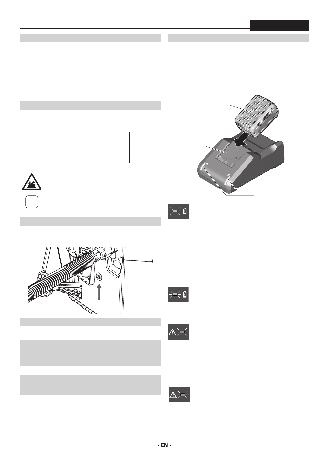
CHARGING BATTERY PACK
The battery charger charges the battery. The charger will bring a fully
depleted battery to a full charge in approximately 45 minutes.
Plug charger cord into your standard power outlet.
With no battery pack inserted, the charger’s green indicator light will
go ON. This indicates the charger is receiving power and the charger
is ready for operation.
4
3
2
1
When you insert the battery pack (1) into the charger
(2). The charger’s green indicator light (4) will begin to
“BLINK”. This indicates that the battery is receiving a fast
charge.
Once approximately 80% battery capacity has been reached, the
blinking of green light will slow down, indicating that fast charging is
now complete. If battery remains in charger, the charging process is
completed in Long Life charging mode.
The purpose of the rapidly “BLINKING” green light is to indicate
that the battery pack is fast-charging. It does not indicate the exact
point of full charge. The light will stop blinking when battery is fully
charged.
Continuous green battery charger light (4) indicates that
the battery is fully charged.
However, the battery pack may be used at any time, even
if the green light is still blinking.
A steady red indicator light (3) means that the battery
pack is outside the proper temperature ranges (too hot
or too cold) so the charger will not begin the charging
process. Charging (Fast or long Life Charging Mode) is
only possible when the temperature range of the battery
pack is between 32°F (0°C) and 113°F (45°C).
As soon as the battery pack reaches the correct
temperature range, the battery charger will automatically
switch to fast charging.
If the red indicator light (3) is “BLINKING”, the battery
pack cannot accept a charge. This may be due to the
contacts on the charger or battery pack is contaminated,
the battery pack itself may be defective, or battery may
be wrong type for this charger.
7
IMPORTANT SAFETY INFORMATION / SPECIFICATIONS
ControlMax 1650
• Conrm battery compatibility with charger by checking list of
genuine Bosch/AMPShare battery packs
• If applicable, insert another compatible battery pack into
charger to verify charger is working properly.
• Clean the contacts of the charger or battery pack (e. g. by using
a cotton swab and alcohol on battery and charger terminals or
inserting and removing the battery several times) or replace the
battery pack, as required.
When the battery pack is fully charged, unplug the charger (unless
you’re charging another battery pack) and slip the battery pack back
into the tool.
SPECIFICATIONS
ControlMax 1650 18V
Maximum Pressure 1600 PSI (11.1 MPa)
Flow Rate 0.24 GPM (0.91 LPM)
Tank Capacity 1.25 gallon (4.7 l)
Max. tip 0.015”
Max. hose length 50’ (9’ is included)
Power Requirement 2 Ah, 18V battery pack (2)
Overheating
protection
This sprayer has a built-in protective
device to prevent damage from
overheating. The sprayer may
automatically shut down after heavy
use. If this happens, turn switch OFF
(0), remove the battery and allow to
cool for 20-30 minutes and resume
spraying.
CAPABILITY
Sprays a variety of paints (oil-based and latex), primers, stains,
preservatives and other nonabrasive materials.
DO NOT USE!
This pump should not be used with textured materials, block ller,
lacquers, industrial enamels, or asphalt sealer or materials containing
HHC. See coating supplier if ash point is not listed on the container.
Do not spray or clean with liquids having a ash point of less than
38˚C (100˚F). Flash point is the temperature at which a uid can
produce enough vapor to ignite.
SAFETY FEATURES
Spray gun trigger lock and pressure diuser; built-in tip safety guard;
PRIME/SPRAY knob for safe pressure release. Conforms to UL STD
1450. Certied to CSA C22.2 NO 68.
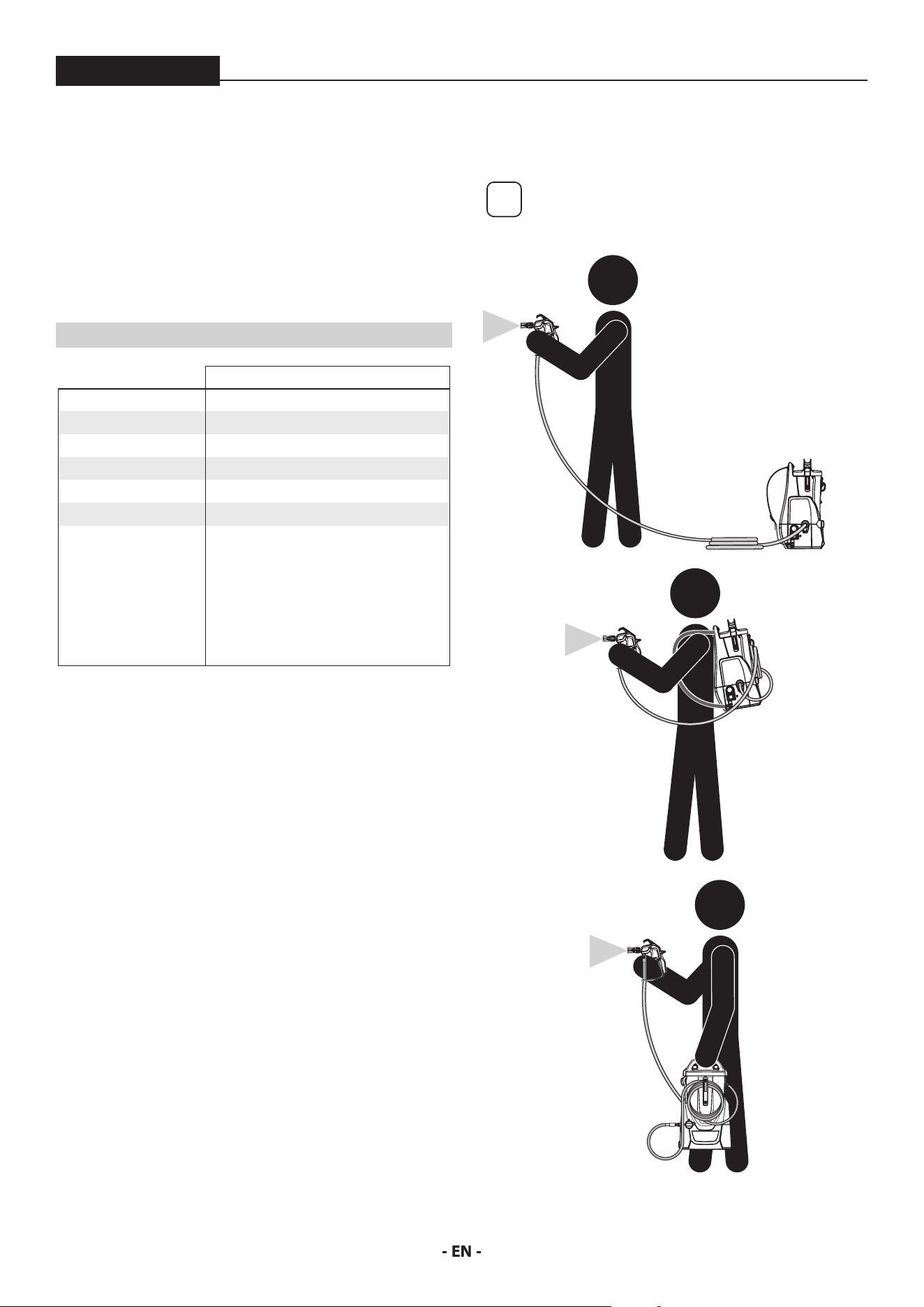
MODES OF USE
This sprayer can either be used as a regular stationary pump* or can
be used in backpack mode.
i
*In order to use in stationary mode, it is
recommended that a longer hose be purchased
separately.
STATIONARY MODE
BACKPACK MODE
CARRY MODE
8
PARTS AND COMPONENTS
ControlMax 1650
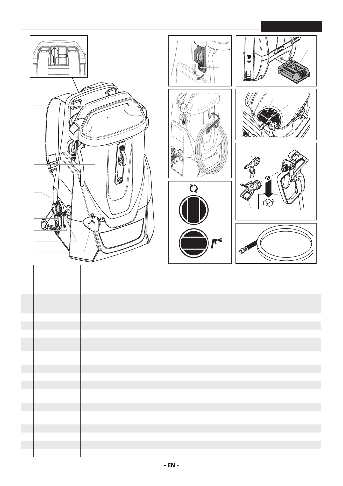
# ITEM DESCRIPTION
1 Tank lid / carry
handle
When properly secured, the handle on top of the lid can be used to carry the unit. To remove the lid, pull the tabs (a) on
the sides of the lid down and away from the tank. These tabs must be latched underneath the hooks (b) on the sides of the
tank to be properly secured.
2 Straps The straps allow the user to ‘wear’ the unit like a backpack for increased mobility. It is recommended that the straps be
adjusted to t the user prior to the unit being used. To tighten, pull the excess strap down from the slider. To loosen, allow
the strap to come back up through the slider.
3 Material return tube Fluid is sent out through the return tube and back into the tank when the PRIME/SPRAY knob is in the PRIME position.
4 Tank Where the spray material is drawn from.
5 Hose wrap When using in backpack mode, the excess hose can be looped and secured here.
6 Battery compartment The battery pack (a) powers the unit. During usage it is installed in the area at the bottom of the unit on the same side as
the straps.
7 Speed control knob The speedspeed control knob regulates the amount of force the pump uses to push the uid and can be adjusted for desired
spray pattern.
8 ON/OFF switch Switches the unit ON (I) and OFF (0).
9 LED indictor See “Error Codes”, page 6.
10 Spray hose port The connection between the pump and the spray hose.
11 PRIME/SPRAY knob The PRIME/SPRAY knob directs material to the material return tube when set to PRIME or to spray hose when set to SPRAY.
The PRIME/SPRAY knob can be turned in either direction to desired setting.
12 Inlet lter The inlet lter is designed to prevent any debris that may be in the spray material from entering the pump.
13 Pusher valve The pusher valve is designed to free the inlet valve which may become stuck due to dried materials. The pusher stem is
activated manually by the user.
14 Spray gun The spray gun controls the delivery of the material being pumped.
15 Tip guard The spray guard reduces the risk of injection injury. Saddle seal (a) comes preassembled inside the spray guard
16 Spray tip The spray tip atomizes the spray material and forms the spray pattern. Extra tips can be stored in the rear of the unit (a).
17 Spray hose The spray hose connects the spray gun to the pump.
PRIME
SPRAY
10
9
6
11
7
3
2
4
5
1
8
14
16
15
17
11
1
6
5
a
13
12
a
16a
b
a
9
ASSEMBLY
ControlMax 1650
ASSEMBLY
Do not install the battery until assembly is complete.
i
Remove the plastic cap from the spray hose port and
the plastic plug from the end of the spray hose prior
to assembly.
TOOLS NEEDED
• Two 6” adjustable wrenches
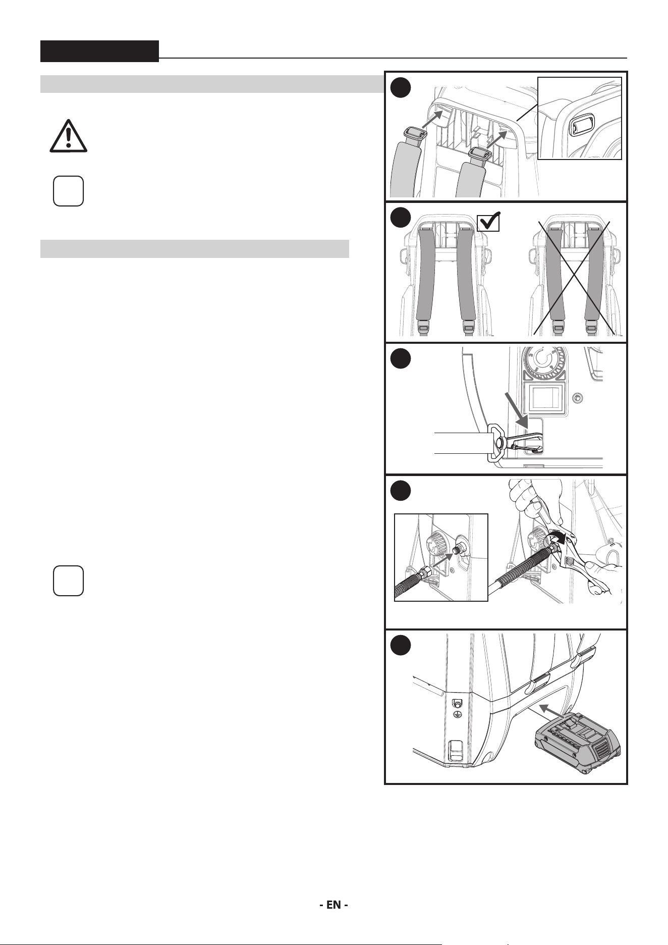
ATTACH THE STRAPS
1. Bring the slider through the slot in the unit as shown. Once through,
orient it vertically so it catches (a). Repeat this step for the other strap.
2. The thick part of the strap should bow inwards to the center of the
unit.
3. Add strap clips to the mounting points on the bottom of the unit.
Make sure the clips are oriented as shown.
The user should place the unit over their shoulders prior to usage to
make sure the straps are adjusted properly.
ATTACH THE HOSE
4. Thread the end of the high pressure spray hose to the spray hose port.
Hold the port with an adjustable wrench, and tighten the hose with
the other. Do not over-tighten.
INSTALL THE BATTERY
i
Prior to installing the battery, make sure it has been
suciently charged. Refer to Charging the Battery
Pack, page 6.
5. Slide the charged battery into the unit as shown. Make sure it clicks
into place.
1
A
2
3
4
5
10
BEFORE YOU BEGIN
ControlMax 1650
i
This section contains instructions that will
be repeated throughout this manual. Read
and understand this section before using the
equipment.
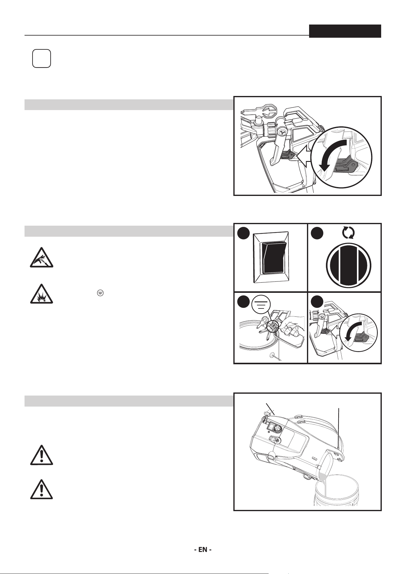
SPRAY GUN TRIGGER LOCK
Engage the trigger lock whenever instructed.
To lock the trigger, ip the trigger lock down until it stops in place behind
the trigger.
To unlock the trigger, ip the trigger lock up until it snaps into place on
the gun handle.
MOVING / EMPTYING THE SPRAYER
When lifting the sprayer in order to move it or to empty the tank, secure
with both hands in the grooved handle area in the battery garage and on
the top handle.
The sprayer can be heavy when lled with spraying
material. Make sure to lift with your legs and not
your back in order to reduce the risk of injury.
At
tention
Do not use the hose as a strength member to pull or
lift the equipment.
This pump is liquid-cooled. Do not allow the
sprayer to run without paint or water in the tank.
PRESSURE RELIEF PROCEDURE
Be sure to follow the Pressure Relief Procedure
when shutting the unit o for any purpose. This
procedure is used to relieve pressure from the
spray hose.
Explosion hazard. Make sure the spray gun is
grounded (
) when relieving pressure. Hold the
metal nut on the tip guard or diuser rmly against
a metal container when instructed to trigger the
gun.
1. Turn the power OFF (0).
2. Lock the spray gun. Turn the PRIME/SPRAY knob to PRIME.
3. Unlock the spray gun. Briey pull the trigger to fully relieve pressure
from the system (see Explosion Hazard warning above).
4. Lock the spray gun.
LOCKED
HANDLE
HANDLE
1
0
2
3 4
11
LOAD MATERIAL
ControlMax 1650
i
These steps will prime the system and get it
ready to spray.
Scan the QR code for product support and
content, including How-To videos.
YOU WILL NEED
• The material you plan to spray
• Waste bucket
i
Recommendation: It is good practice to
perform the steps on this page using water
to familiarize yourself with the function of
the unit as well as to ensure the unit is set up
properly.
i
Recommendation: Always use new spray
material or material that has been thoroughly
strained. Old material often contains debris
that can clog the system.
At
tention
Take care to prevent material spills. Make sure
to use drop cloths and mask anything that is
in the spraying area and could accidentally be
sprayed.
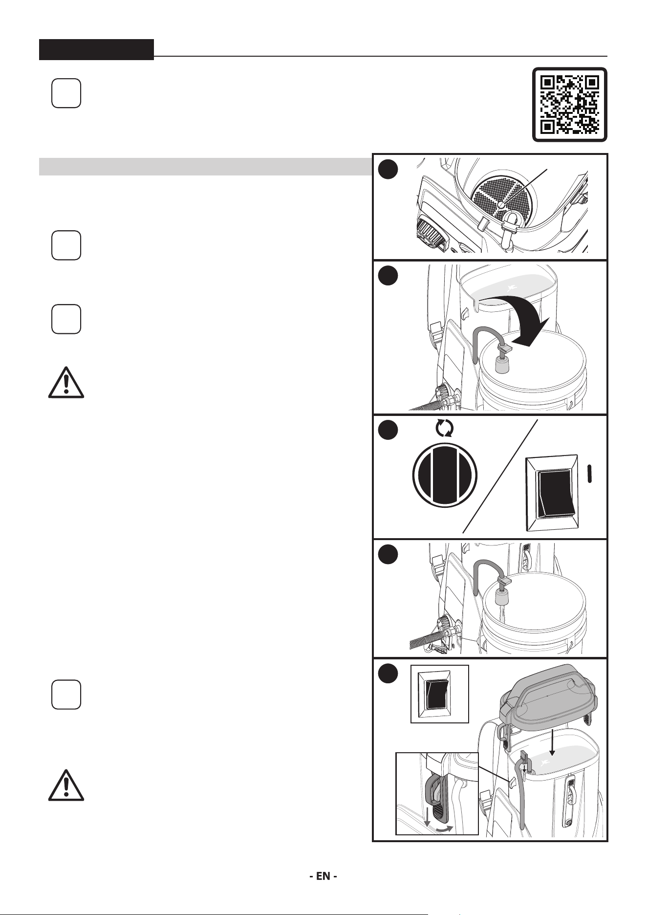
1. Remove the tank lid. Push tab on lter twice to ensure inlet
valve operation.
2. Fill the tank with spray material. Pull the return tube from the
tank and hold it over a waste container.
3. Turn the PRIME/SPRAY knob to PRIME.
Turn the power ON (l). Do not run the sprayer dry.
Slowly turn the speed control knob clockwise to setting ‘2’.
4. Allow pump to run until you see spray material owing from the
return tube (A).
5. Turn power OFF (0).
Place return tube back into position over the tank (B). Make sure
the grommet is positioned correctly into the slot on the tank.
Replace the tank lid. Make sure the lid tabs (C) are in position
over the hooks.
i
For consistent color results, add spray material
regularly in order to mix it.
When the tank empties, stop spraying
immediately. Turn the PRIME/SPRAY knob to
PRIME and rell the tank. It is recommended
to rell the tank before it is completely empty.
At
tention
The tank lid should t snugly over the tank,
but it is not designed to be air- or liquid-tight.
Do not tip the unit more than 30˚ from vertical
when it is lled with spray material.
1
PUSH
2
3
0
4
A
5
B
0
C
12
SPRAYING
ControlMax 1650
i
Follow these steps to deliver spray material from the tank to
the spray gun.
YOU WILL NEED
• Waste bucket,
• Scrap material / cardboard
• Adjustable wrench
• Drop cloths to protect oors and furnishings from overspray
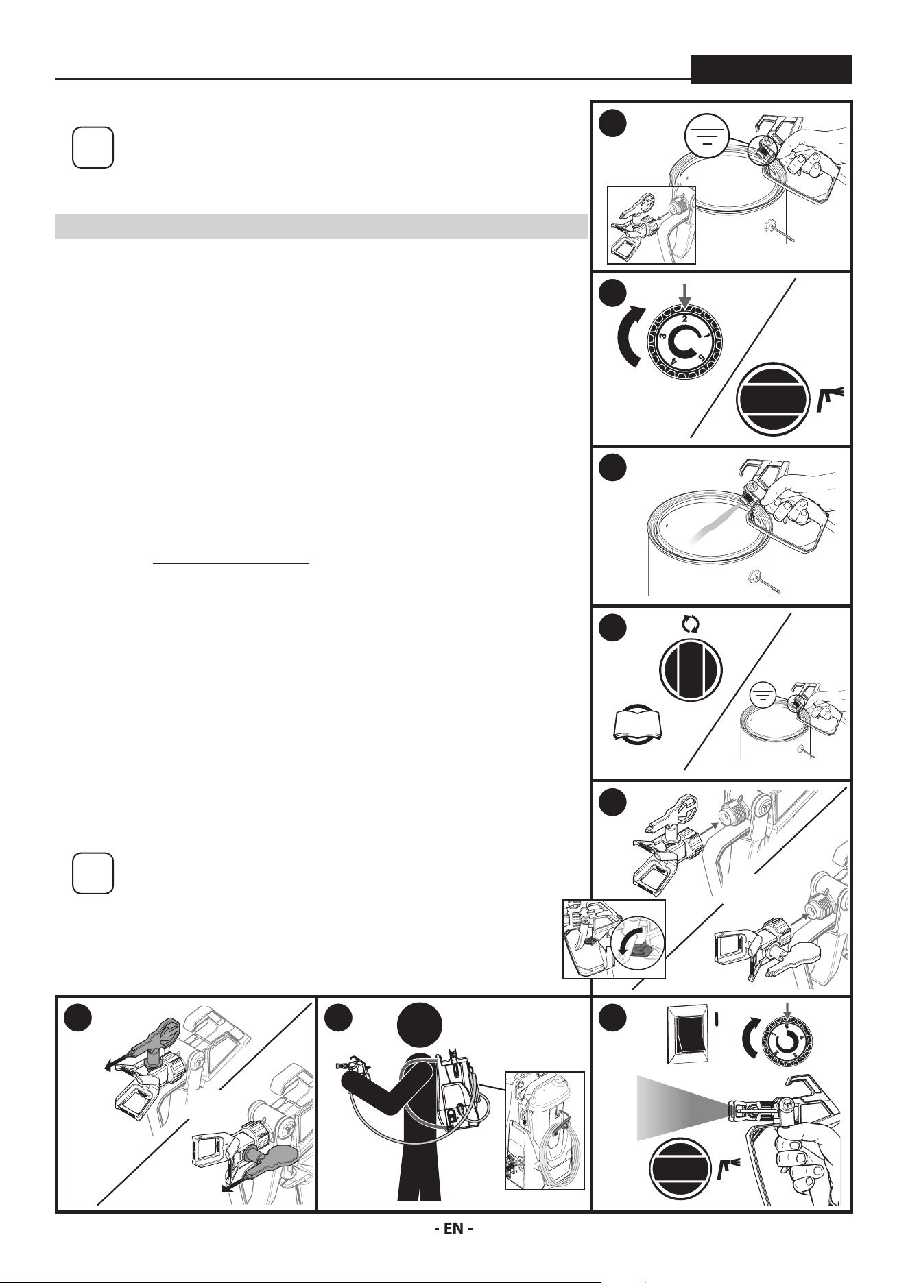
1. Make sure the tip and spray guard are removed. Point the spray gun into
a separate waste container. Unlock the spray gun trigger.
Squeeze and hold trigger for steps 2-3.
2. Turn the power ON (l). Slowly turn the speed control knob clockwise to
setting ‘2’.
Turn the PRIME/SPRAY knob to SPRAY.
3. Continue to squeeze trigger until the material is owing freely through the
spray gun.
4. Perform the Pressure Relief Procedure, page 10.
5. Make sure the spray gun trigger is locked. Thread the spray tip guard
assembly onto the gun. Tighten with a wrench.
6. Make sure the spray tip is rotated forward to the spray position, with the
arrow on the tip facing forward.
Unlock the spray gun trigger.
7. If using in backpack mode, carefully put the straps over your shoulders to
secure the unit. Make sure any excess hose is stored in the hose wrap.
8. Turn the power ON (l). Turn the PRIME/SPRAY knob to SPRAY. Slowly turn
the speed control knob clockwise to the maximum setting (5).
Point the spray gun at a piece of scrap material/cardboard.
Pull the trigger and practice spraying (see page 13).
i
Motor will cycle ON and OFF while spraying to regulate
pressure. This is normal.
The sprayer will not blow air. There must be spray material
or water in the tank.
Do not run the sprayer without spray material or water in
the tank.
1
2
3
4
P. 10
5
OR
6
OR
7 8
0
13
PRACTICE SPRAYING
ControlMax 1650
i
If the spray pattern becomes distorted or stops spraying completely while the gun is triggered, follow any or all the
procedures listed on pages 14-15.
If you plan to be away from your spray project for more than one hour, follow the Short Term Storage instructions on
page 16.
If you have diculty achieving a good spray pattern, your spray tip may not be ideal for the type of material you are
spraying. Refer to Troubleshooting page, 22.
YOU WILL NEED
• A surface to practice spraying (wood, carboard
or scrap drywall)
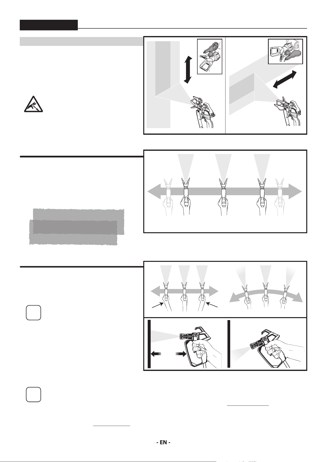
While spraying, the spray guard / tip assembly can be
rotated to better suit your spraying motion.
Lock the spray gun trigger prior
to rotating the spray guard / tip
assembly.
Make sure the spray guard nut is
not loosened after rotating.
Flex your wrist as you move in order to keep gun
parallel to the surface.
Hold the spray gun level.
i
The distance from the spray gun
to the spray object should not
exceed 16 inches.
Trigger gun after starting the stroke. Release the
trigger before ending the stroke.
The spray gun should be moving when the trigger is
pulled and released.
Overlap each stroke by about 50%. This will ensure
an even coating.
50% Overlap
CORRECT
INCORRECT
10” - 12”
(25 - 30 cm)
CORRECT
10” - 12”
(25 - 30 cm)
INCORRECT
Start
stroke
End
stroke
Pull
trigger
Release
trigger
Move
steadily
14
SPRAYING TROUBLESHOOTING - UNCLOGGING THE SPRAY TIP / SPRAY GUN FILTER
ControlMax 1650
i
If the spray pattern becomes distorted or stops
spraying completely while the gun is triggered,
the spray tip or spray gun lter could be clogged.
Follow the steps below.
UNCLOGGING THE SPRAY TIP
YOU WILL NEED:
• Scrap material / cardboard
Do not attempt to unclog or clean the tip
with your nger. High pressure uid can
cause injection injury.
1. Lock the spray gun.
2. Rotate spray tip 180 degrees from its current position.
i
If spray tip is dicult to rotate, relieve
pressure by:
1) slowly turn PRIME/SPRAY knob to PRIME,
2) unlock the spray gun and
3) squeeze trigger while pointing at scrap
material/cardboard.
Release trigger, lock the spray gun, and try
rotating spray tip again.
3. Make sure the PRIME/SPRAY knob is turned to SPRAY.
Unlock the spray gun.
Point at a piece of scrap material / cardboard and squeeze
trigger until material comes out in a high pressure stream.
Release the trigger and lock the spray gun.
4. Rotate spray tip forward to the spray position. Unlock the
spray gun and resume spraying.
UNCLOGGING THE SPRAY GUN FILTER
YOU WILL NEED:
• Straight slot screwdriver
• Warm, soapy water for latex material / mineral spirits for oil based materials
• Replacement spray gun lter (if necessary)
At
tention
Never clean the lter by poking it with a sharp object.
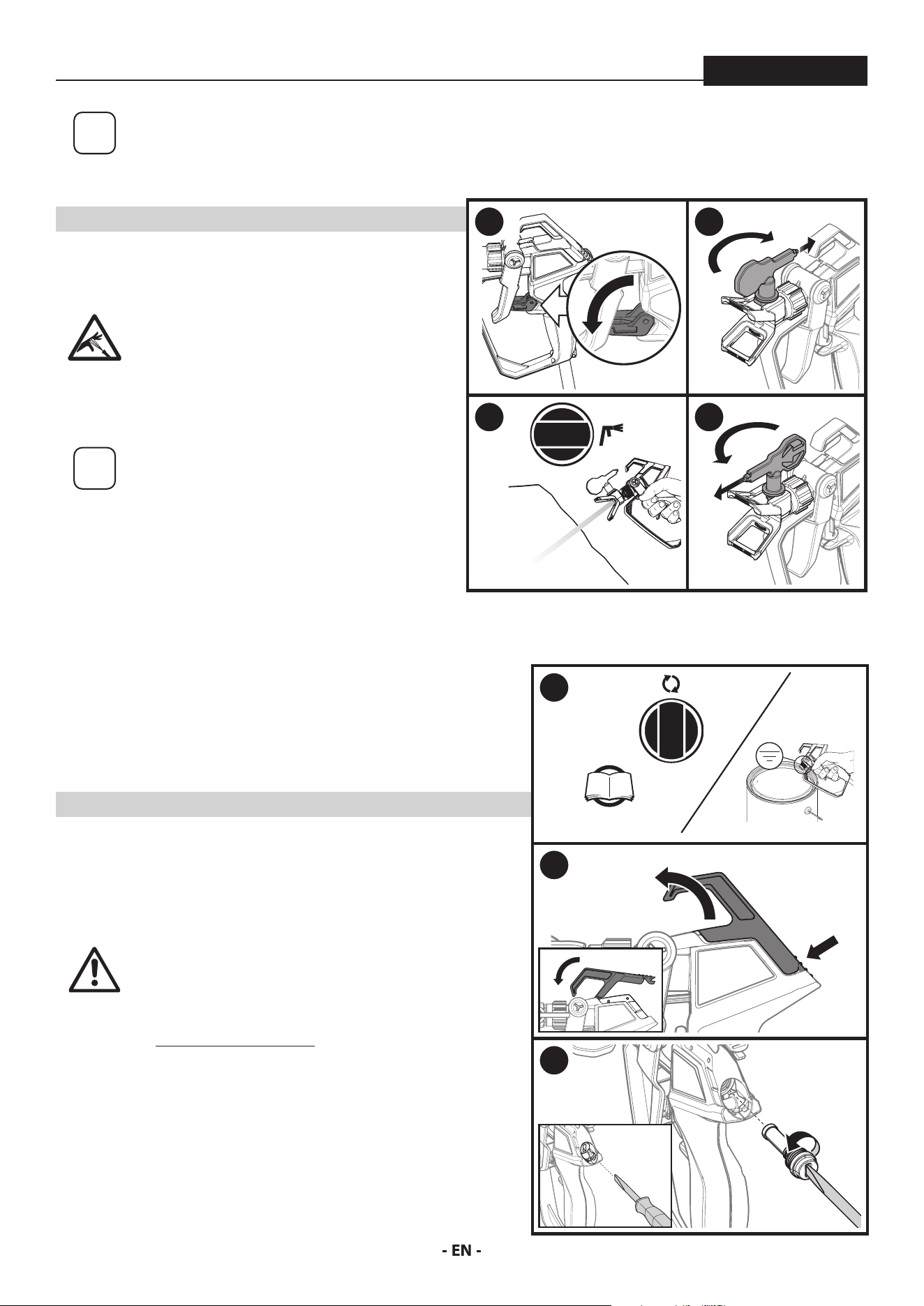
1. Perform the Pressure Relief Procedure, page 10.
2. Press on the hook latch and pull on the hook on the top of the gun until
it opens.
3. Using a straight-slot screwdriver, remove the lter from the spray gun.
Clean with appropriate cleaning solution (warm, soapy water for latex
materials; mineral spirits for oil-based materials).
Inspect the lter for damage. Replace if any holes or tears are found.
4. Replace the lter and tighten with the screwdriver. Snap the hook back
in place.
1 2
3 4
1
P. 10
2
PRESS
PULL
3
15
SPRAYING TROUBLESHOOTING - CLEAN THE INLET FILTER
ControlMax 1650
YOU WILL NEED
i
If the spray pattern becomes distorted or stops
spraying completely while the gun is triggered,
the inlet lter could be clogged. Follow the steps
below.
• Warm, soapy water for latex material
• Mineral spirits for oil based materials
At
tention
Make sure your oors and furnishings are covered
with drop cloths to prevent accidental drips.
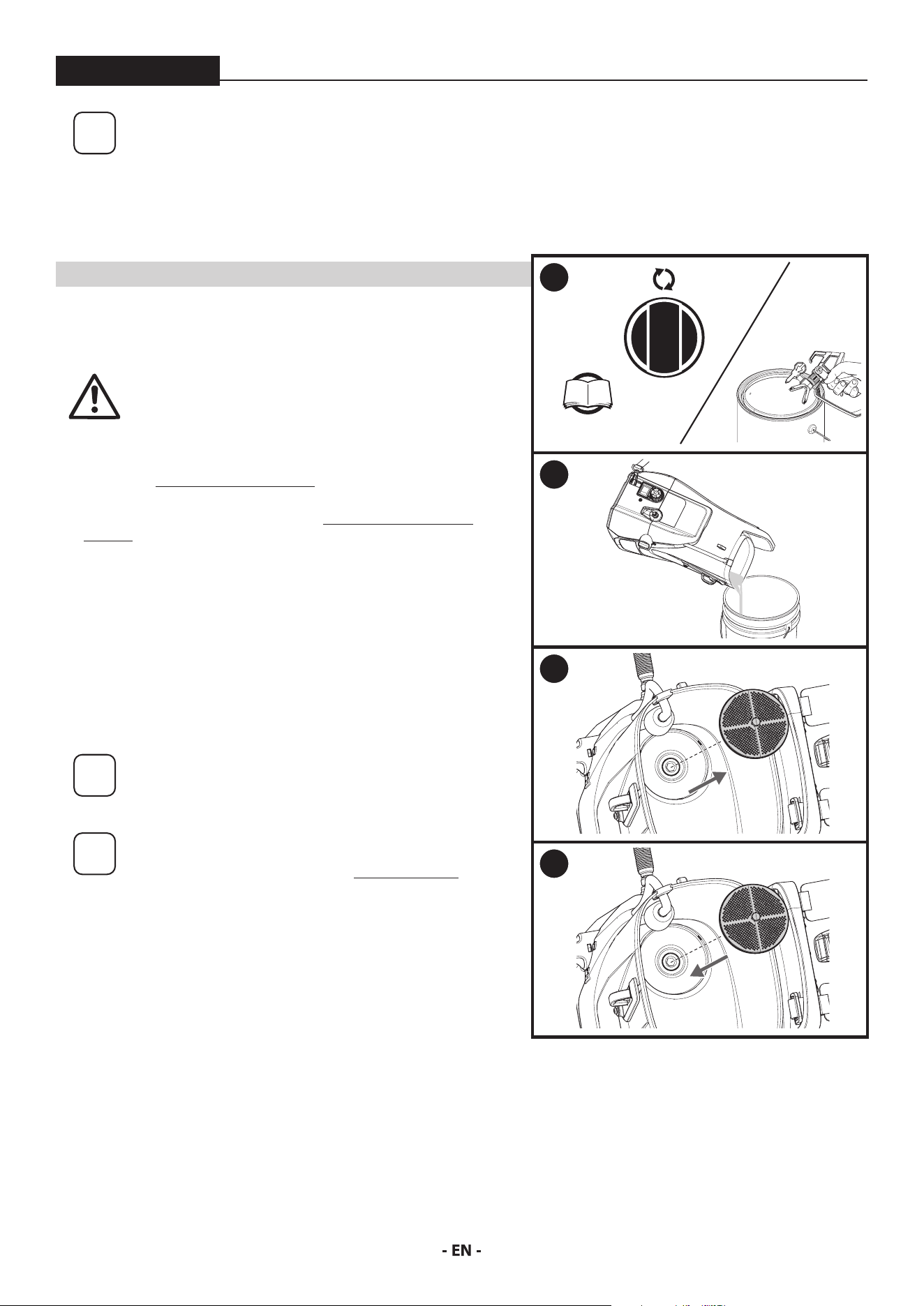
1. Perform the Pressure Relief Procedure, page 10.
2. Empty the tank of spray material (see Moving / Emptying the
Sprayer, page 10. Do not run the sprayer without spray material or
water in the tank.
3. Remove inlet lter from tank.
Clean the inlet lter using the appropriate cleaning solution (warm,
soapy water with latex- and water-based materials, mineral spirits
with oil-based paints or stains).
4. Snap the inlet lter back into place.
Resume spraying (follow steps on pages 12-13)
i
If the inlet lter clogs, it is a good idea to strain the
material you are using prior to lling the hopper.
i
If after completing all of the steps in Spraying
Troubleshooting you are still experiencing
problems spraying, refer to the Troubleshooting
section (page 22).
1
P. 10
2
3
4
16
SHORT TERM STORAGE
ControlMax 1650
i
This procedure should be used when taking a short
term break or when ending your project for the day.
If your break is longer than 16 hours follow Cleanup
instructions, pages 17-18.
YOU WILL NEED
• Water
• Plastic bag
• Damp rags
• Stir stick
i
Instructions are for latex materials only! If using oil
based material follow instructions for Cleanup on
pages 17-18.
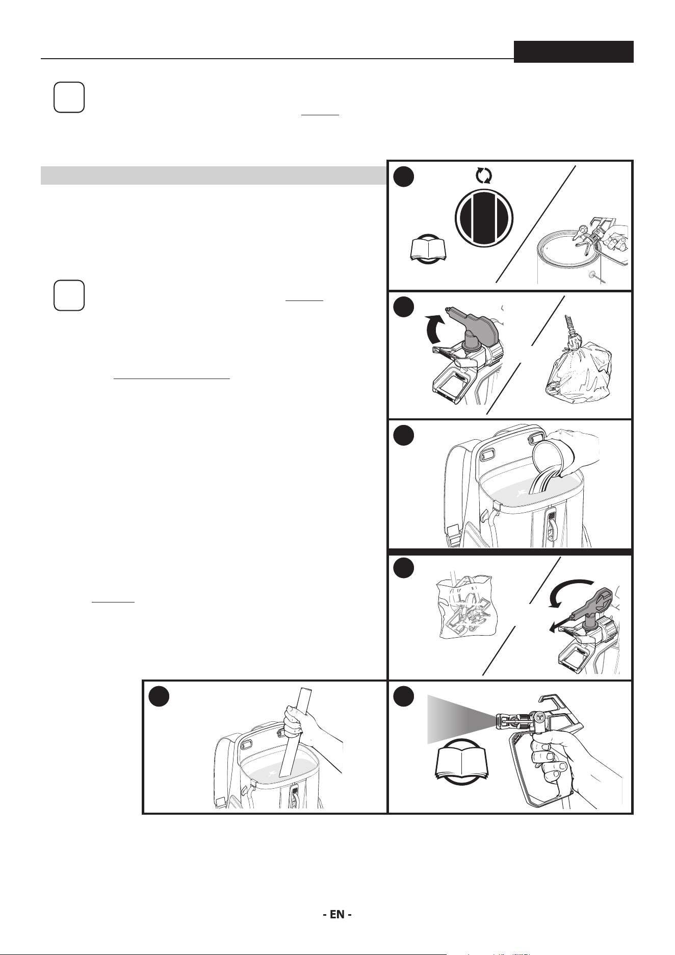
SHUTDOWN
1. Perform the Pressure Relief Procedure, page 10.
2. Turn spray tip 90˚. This will prevent air from drying out any spray
material that may be inside the spray tip. Wrap spray tip and guard
in a damp rag and then place entire spray gun in plastic bag.
3. Pour 1/2 cup water slowly on the top of the paint to prevent the
paint from drying. Replace the hopper lid.
Place the entire spraying system out of the sun.
STARTUP
4. Remove the spray gun from the plastic bag. Turn the spray tip back
to the spraying position.
5. If water was added during shut down, stir water into material with
the stir stick.
6. Follow Spraying instructions, page 12.
1
P. 10
2
AND
3
4
AND
5 6
P. 12
17
CLEANUP
ControlMax 1650
CLEANING NOTES - READ BEFORE CLEANING
• When using latex material, clean sprayer and components with
warm, soapy water. For oil based material use mineral spirits.
Never use mineral spirits with latex materials.
• NEVER use gasoline to clean sprayer.
• Dispose of used cleaning solution properly.
• Thorough cleaning and lubrication of sprayer is important to
ensure proper operation after storage.
• If you ush your sprayer with mineral spirits, repeat Cleanup
instructions using warm, soapy water.
• DO NOT SPRAY PUMP ASSEMBLY WITH WATER OR CLEANING
SOLUTION.
YOU WILL NEED
• Warm, soapy water if using latex material
• Mineral spirits if using oil-based material
• Empty waste container
• Soft-bristled brush
i
It is recommended that the shoulder straps be removed
prior to cleaning. This will prevent them from getting wet or
stained during cleanup. Wait for unit to completely dry before
reinstalling the straps. Do not store the straps inside the tank.
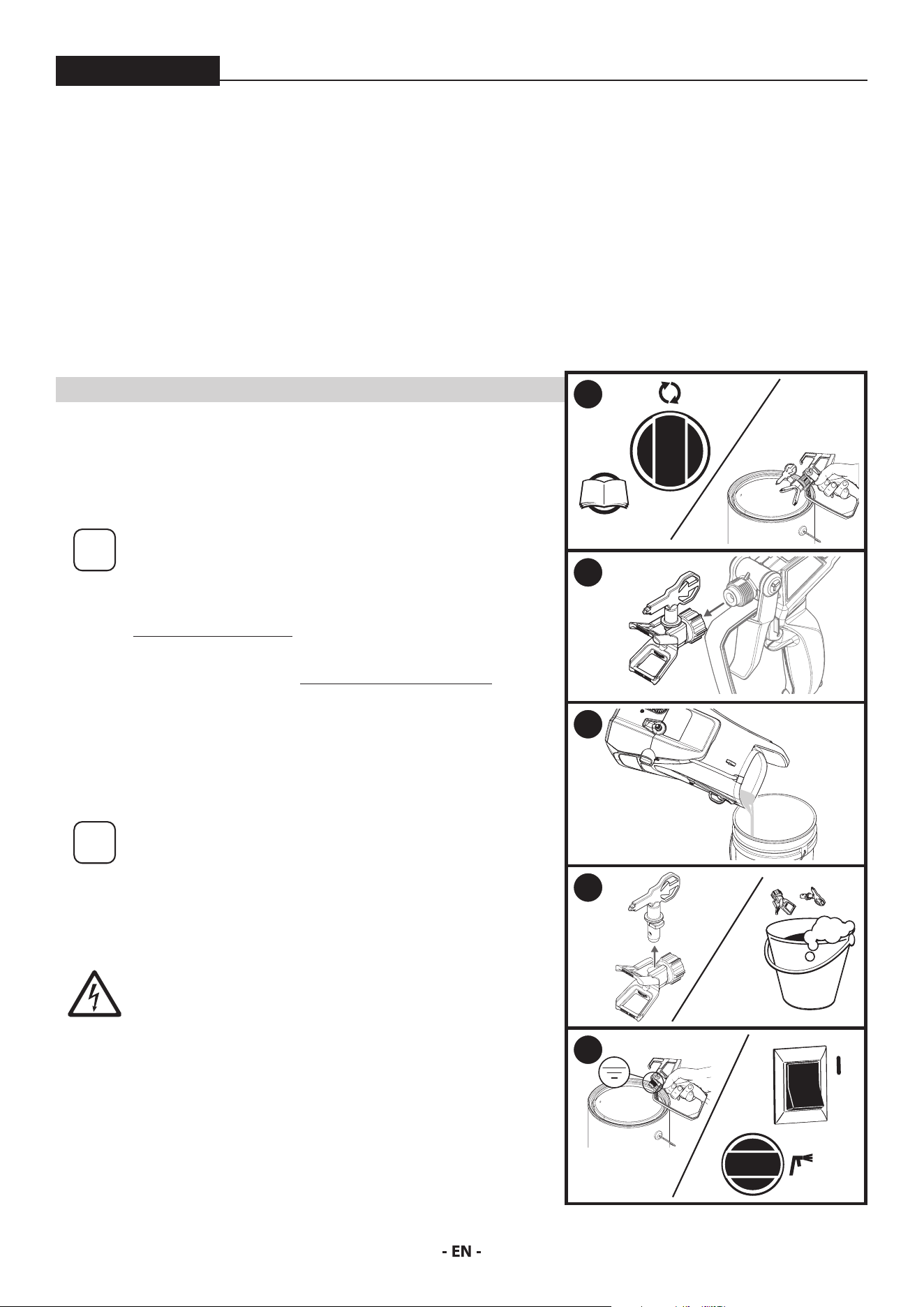
1. Perform Pressure Relief Procedure (page 10).
2. Remove the tip guard from the spray gun.
3. Empty the tank of spray material (see Moving / Emptying the Sprayer, page 10.
Rinse the tank with the appropriate cleaning solution until clean.
Dispose of the cleaning solution, and then ll the tank again with NEW cleaning
solution. Do not run the sprayer without spray material or water in the tank.
4. Remove the spray tip from the tip guard. Carefully place both into the tank full
of cleaning solution.
i
Allowing the spray tip and tip guard to soak in the tank while
ushing will make it easier to clean them afterwards.
Take care not to lose the saddle seat located inside the rear of
the spray guard.
5. Point the spray gun at the side of a waste container.
Ground the gun against the side of a metal waste container if
ushing with mineral spirits.
DO NOT SPRAY THE PUMP ASSEMBLY WITH WATER OR
CLEANING SOLUTION.
While squeezing the trigger, turn the sprayer ON (l), and turn the PRIME/SPRAY
knob to SPRAY.
Continue squeezing the trigger until uid is coming out clear. You may need to
get new cleaning solution and repeat.
The spayer will not spray air. It must have spray material or water in the tank.
(Continued on the next page)
FOLLOW THESE STEPS WHENEVER CLEANING WITH
MINERAL SPIRITS:
• If spraying or cleaning with oil-based materials, the spray gun
must be grounded while preparing the spray hose or cleaning.
• Ground the gun by holding it against the edge of a metal
container while purging. Failure to do so may lead to a static
electric discharge which may cause a re.
• Always ush spray gun at least one hose length from spray
pump.
• If collecting ushed solvent in one gallon metal container, place
it into an empty ve gallon container, then ush.
• Area must be free from vapors.
• Follow all cleanup instructions.
1
P. 10
2
3
4
5
0
18
CLEANUP - CONTINUED
ControlMax 1650
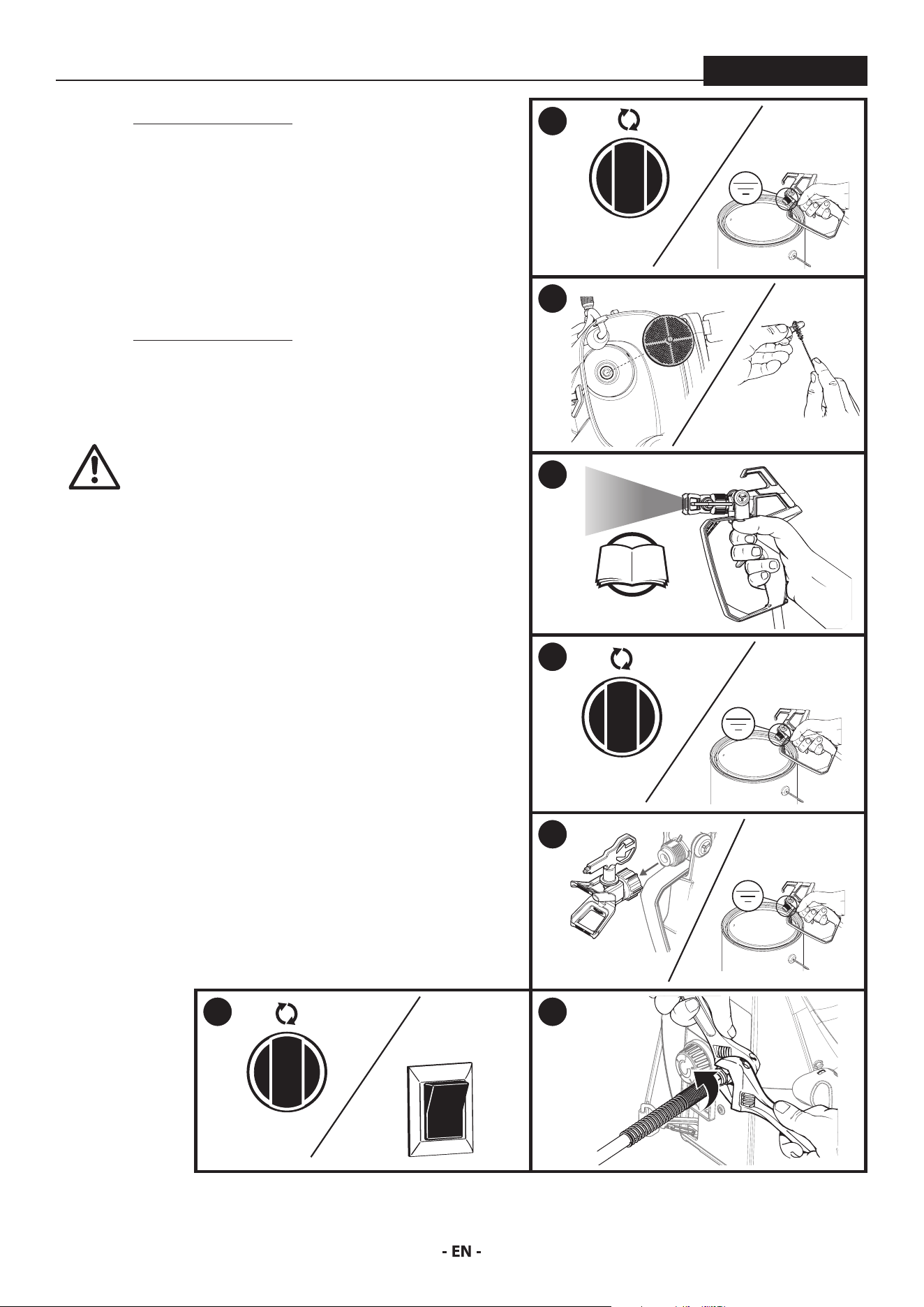
6. Perform Pressure Relief Procedure (page 10).
7. Remove the inlet lter. Clean by hand using a soft-bristled brush.
Snap back into place when clean.
Remove the tip guard and spray tip from the cleaning solution.
Clean by hand using a soft bristled brush. Reinstall onto spray gun
when clean.
8. IMPORTANT STEP: Fill the tank with warm, soapy water. Following
steps 5-8 in the “Spraying” section, spray at least one gallon of warm,
soapy water. This will ensure that the spray tip will be completely
clean for the next use.
9. Perform Pressure Relief Procedure (page 10).
10. Remove the spray tip assembly.
Repeat step 5 from above, continuing to squeeze the trigger until
uid comes out clear.
At
tention
This pump is liquid-cooled. Do not allow the
sprayer to run without paint or water in the tank.
11. Turn PRIME/SPRAY knob to PRIME. Turn power OFF.
Replace the spray tip/tip guard assembly.
12. Place a wrench on the outlet valve to secure it. Using the second
wrench, remove the spray hose.
Hold end of the spray hose and spray gun higher than the other
and drain the hose of all cleaning solution into a waste container.
Properly dispose of the cleaning solution.
Move on to the Long Term Storage steps, next page.
6
7
8
P. 12
9
10
11
0
12
19
LONG TERM STORAGE
ControlMax 1650
i
Follow these steps to prepare your sprayer for
long-term storage.
YOU WILL NEED
• Light household oil (such as 10W30 motor oil or vegetable oil for
example) / Piston Lube
• Rags
• Two adjustable wrenches
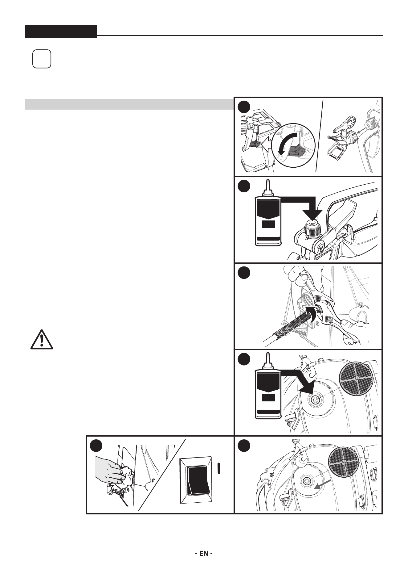
1. Lock the spray gun and remove the tip guard and tip.
2. Pour a few drops of All Guard into the hole in the gun diuser. Pull
the trigger a couple of times. Reassemble the spray tip.
A light oil can be substituted (such as 10W30 motor oil or vegetable
oil for example).
3. Place a wrench on the outlet valve to secure it. Using the second
wrench, remove the spray hose.
4. Remove the inlet lter. Pour approximately 2 ounces of Piston
Lube inside the inlet valve housing. A light oil can be substituted
(such as 10W30 motor oil or vegetable oil for example).
5. Cover the outlet valve with a rag. Turn the power ON (l) and let the
pump run for 5 seconds.
Turn power OFF.
6. Replace inlet lter. Wipe entire unit, hose, and spray gun to
remove accumulated spray material.
At
tention
Store the unit indoors with the power cord
wrapped around the base.
1
2
HOUSEHOLD
OIL
3
4
HOUSEHOLD
OIL
5
0
6
20
MAINTENANCE - CLEANING THE INLET VALVE
ControlMax 1650
i
Cleaning or servicing the inlet valve may be required if the unit has priming problems.
Priming problems may be prevented by properly cleaning the sprayer and following
the long-term storage steps.
YOU WILL NEED
• 8 mm (5/16”) hex wrench
• Needle nose pliers
• Warm, soapy water if using latex material
• Mineral spirits for oil based material
• Household oil (such as 10W30 motor oil or vegetable oil for example)
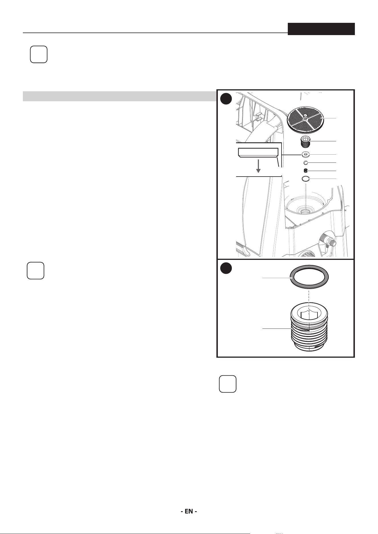
1. Perform the Pressure Relief Procedure, found in the main instruction
manual, to ensure the pump is shut o and depressurized. Remove
the tank lid.
Remove the inlet lter (1).
Using the lid as a tray for the parts, insert an 8 mm (5/16”) hex wrench
into the hex opening (2) and unscrew the inlet valve tting (2) from
the sprayer.
You may need to use a ball point pen, tweezers, screwdriver, O-ring
pick, and/or needle nose pliers to remove the inlet valve seat (3),
inlet valve ball (4), spring (5), and O-ring (6). A spare spring (5) is
included with your sprayer.
i
Suggestion for removal of the inlet valve assembly
After removing the inlet lter (1) insert an 8 mm (5/16”)
hex wrench into the hex opening (2) and unscrew the
inlet valve tting (2) from the sprayer.
Snap the lid back onto the sprayer, turn it upside
down, and tap the bottom of the sprayer a few times
to loosen the inlet seat (3), ball (4), and spring (5).
With the sprayer still upside down carefully remove
the lid. Be careful not to lose any of the removed parts
unless you plan to replace them instead of clean them.
Flip the sprayer right-side up again and remove the
O-ring (6) with an O-ring pick or tweezers.
Inspect and clean the inlet valve housing area where the inlet valve
assembly was removed with the appropriate cleaning solution.
2. Lubricate the O-ring (7) with penetrating oil (WD40) and install onto
the inlet tting (8). Lubricate the O-ring (7) once more after it is
installed on the inlet tting.
3. Replace all parts back into the inlet valve housing in the reverse order
of how they were removed.
Note the correct orientation of the inlet valve seat (3). The taper
should be facing downward upon reinstallation.
Replace inlet valve tting (2) by screwing it into the sprayer. Tighten
securely with a 8mm (5/16”) hex wrench. Torque to 50-57 in. lbs (5.5
- 6.5 N.m). Do not overtighten the inlet valve tting.
Replace inlet lter (1).
i
If priming problems persist, you
may need to replace the inlet valve
assembly. Call Product Support (1-800-
328-8251) to order a new inlet valve
assembly.
1
1
2
3
6
4
5
TAPER
2
7
8
21
MAINTENANCE - CLEANING THE OUTLET VALVE
ControlMax 1650
i
Cleaning or servicing the outlet valve may be necessary if spray performance remains
poor after following the steps in the Troubleshooting section. Call Product Support
(1-800-328-8251) to order a new outlet valve assembly.
YOU WILL NEED
• Two 6” adjustable wrenches
• 2.5 mm hex wrench
• Warm, soapy water if using latex material
• Mineral spirits for oil based material
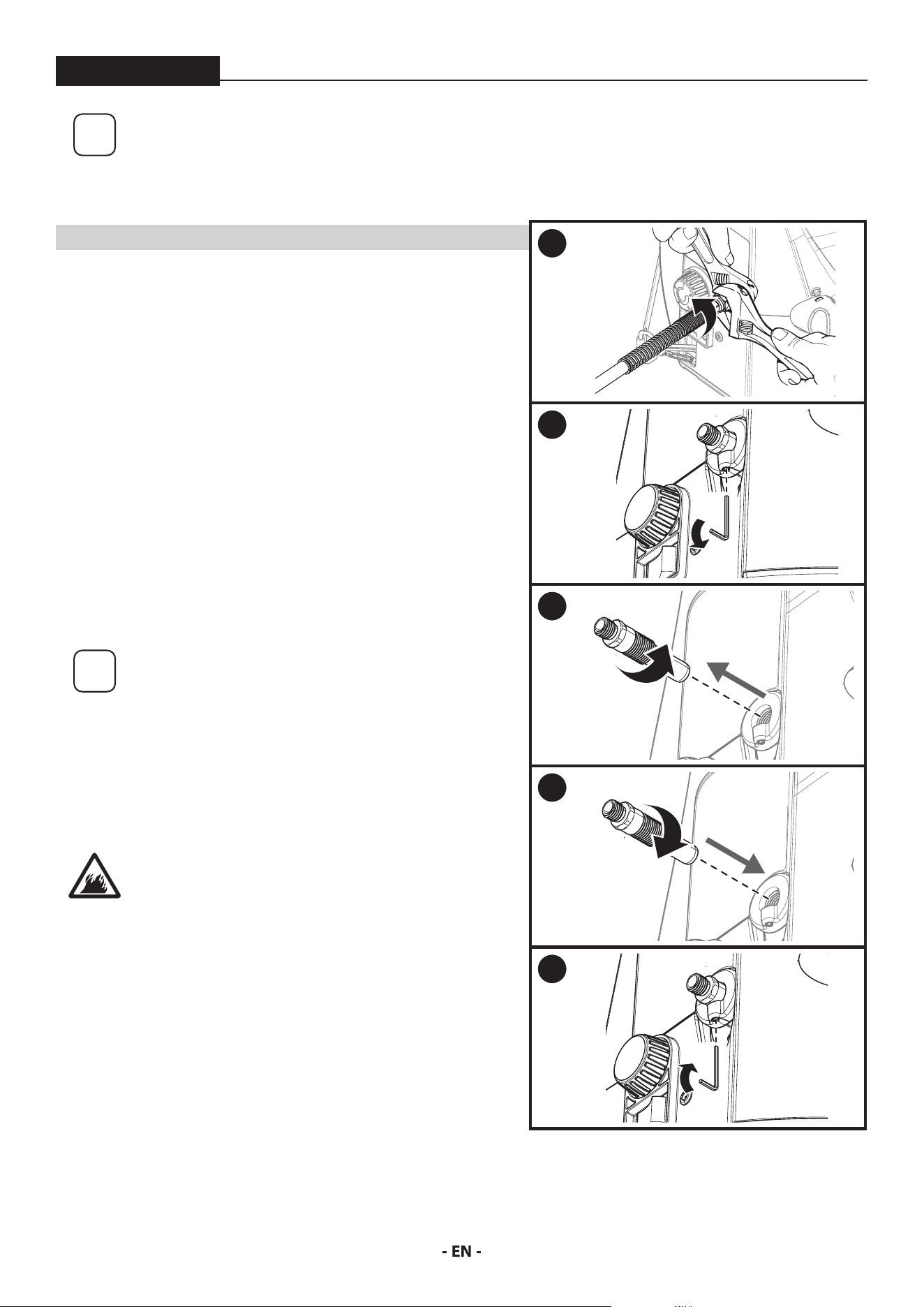
1. Place a wrench on the outlet valve to secure it. Using the second
wrench, remove the spray hose.
2. Loosen (but do not remove) the set screw just underneath the
outlet valve with a 2.5 mm allen wrench.
3. Unscrew outlet valve from outlet valve housing using wrench.
Remove any accumulated material inside outlet valve housing using
appropriate solution for material being used.
Pay particular attention to the ball and seat area at the end of the
outlet valve (opposite the hose end). Remove any accumulated
material.
i
Recommendation: If used with latex-based paints,
ush out the outlet valve with water from a faucet.
4. Replace with new or cleaned outlet valve and tighten with wrench.
Do not over tighten. Torque to 90-110 in-lbs.
5. Tighten the set screw to secure the outet valve. Do not over tighten.
Torque to 20-25 in-lbs.
It is very important to tighten the set screw to
ensure proper grounding of the hose and gun
1
2
3
4
5

22
TROUBLESHOOTING
ControlMax 1650
PROBLEM CAUSE SOLUTION
A. The sprayer does not turn on. 1. The battery is not properly installed / charged.
2. The sprayer is turned OFF (0).
3. The sprayer shuts o while under pressure.
4. There is a problem with sprayer motor.
5. Battery terminals are wet.
6. Spray tip clogged.
1. Reinstall the battery or charge to full.
2. Switch the sprayer ON (l).
3. Motor will cycle ON and OFF while spraying to
regulate pressure. This is normal.
4. Call Technical Service (1-800-328-8251).
5. Wait for terminals to dry or use an air
compressor to dry the terminals.
6. Refer to Unclogging the Spray Tip (p. 14)
B. The sprayer starts but does not
draw material when the PRIME/
SPRAY knob is set to PRIME
1. The inlet valve is stuck from old material.
2. There is no suction at the inlet valve.
3. The inlet lter is clogged.
4. The outlet valve is stuck or contains debris.
5. The inlet valve or outlet valve is worn or
damaged.
6. The PRIME/SPRAY valve is plugged.
1. Push inlet lter tab to release. If still stuck refer
to Cleaning the Inlet Valve (p. 20).
2. Remove inlet lter and check suction by placing
nger on inlet valve. If no suction, refer to
Cleaning the Inlet Valve (p. 20).
3. Refer to Clean the Inlet lter (p. 15) or replace
the inlet lter.
4. Refer to Cleaning the Outlet Valve (p. 21)
5. Replace the inlet valve or outlet valve.
6. Call Technical Service (1-800-328-8251).
C. The sprayer draws material but
the pressure drops when the gun
is triggered (bad spray pattern or
no spray pattern)
1. The spray tip is worn.
2. The inlet lter is clogged.
3. The spray tip is plugged.
4. The spray gun lter is clogged.
5. The material is too heavy or thick.
6. The material is too coarse.
7. The outlet valve assembly is damaged or worn.
1. Replace spray tip with a new one.
2. Refer to Clean the Inlet lter (p. 15), or replace
with a new inlet lter.
3. Refer to Unclogging the Spray Tip (p. 14) or
replace with a new spray tip.
4. Refer to Unclogging the Spray Gun Filter (p.14)
or replace with a new lter.
5. Thin the material.
6. Strain the material.
7. Replace the outlet valve.
D. The PRIME/SPRAY knob is set to
SPRAY and there is ow through
the material return tube
1. The PRIME/SPRAY valve is dirty or worn. 1. Call Technical Service (1-800-328-8251).
E. The spray gun leaks 1. Internal parts of spray gun are worn or dirty. 1. Call Technical Service (1-800-328-8251).
F. The spray tip assembly leaks 1. The tip guard nut is loose.
2. Tip guard was assembled incorrectly.
3. Tip seal is worn
1. Tighten tip guard nut.
2. Remove and assemble correctly.
3. Replace tip seal
G. The spray gun will not spray 1. The spray tip is plugged.
2. The spray tip is in wrong position.
3. PRIME/SPRAY knob not set on SPRAY.
1. Refer to Unclogging the Spray Tip (p. 14).
2. Rotate spray tip to SPRAY position.
3. Turn PRIME/SPRAY knob to SPRAY.
H. The spray pattern is poor (tailing) 1. The spray tip is plugged.
2. The inlet lter is clogged.
3. The spray tip is worn.
4. The material is too heavy or thick.
5. Spray hose is too long.
1. Refer to Unclogging the Spray Tip (p. 14).
2. Refer to Clean the Inlet lter (p. 15)
3. Replace the spray tip.
4. Thin material per manufacturer’s
recommendations.
5. Remove any extra hose length that has been
added.
I. The spray tip will not turn 1. High pressure has locked the spray tip in place. 1. Refer to Unclogging the Spray Tip (p. 14).

23
WARRANTY
ControlMax 1650
AIRLESS PAINT SPRAY EQUIPMENT
This product, manufactured by Titan Tool (Titan), is warranted against defects in material and workmanship for two years following date of
purchase if operated in accordance with Titan’s printed recommendations and instructions. This warranty does not cover damage resulting
from improper use, accidents, user’s negligence or normal wear. This warranty does not cover any defects or damages caused by service or
repair performed by anyone other than a Titan Authorized Service Center.
ANY IMPLIED WARRANTY OF MERCHANTABILITY OR FITNESS FOR A PARTICULAR PURPOSE IS LIMITED TO TWO YEARS FOLLOWING DATE
OF PURCHASE. TITAN SHALL NOT IN ANY EVENT BE LIABLE FOR ANY INCIDENTAL OR CONSEQUENTIAL DAMAGES OF ANY KIND, WHETHER
FOR BREACH OF THIS WARRANTY OR ANY OTHER REASON. THIS WARRANTY DOES NOT APPLY TO ACCESSORIES.
THIS PRODUCT IS DESIGNED FOR HOME USAGE ONLY. IF USED FOR COMMERCIAL OR RENTAL PURPOSES, THIS WARRANTY APPLIES ONLY
FOR 30 DAYS FROM DATE OF PURCHASE.
If any product is defective in material and workmanship during the applicable warranty period, return it with proof of purchase, transportation
prepaid to Titan Tool, 6151 Queens Ave., Otsego, MN 55330. Titan will either repair or replace the product (at Titan’s option) and return it to
you, postage prepaid.
SOME STATES DO NOT ALLOW LIMITATIONS ON HOW LONG AN IMPLIED WARRANTY LASTS OR THE EXCLUSION OF INCIDENTAL OR
CONSEQUENTIAL DAMAGES, SO THE ABOVE LIMITATION AND EXCLUSION MAY NOT APPLY TO YOU. THIS WARRANTY GIVES YOU SPECIFIC
LEGAL RIGHTS, AND YOU MAY ALSO HAVE OTHER RIGHTS WHICH VARY FROM STATE TO STATE.
QUESTIONS?
Call Titan Product Support at:
1-800-328-8251
Register your product online at:
www.titantool.com
68
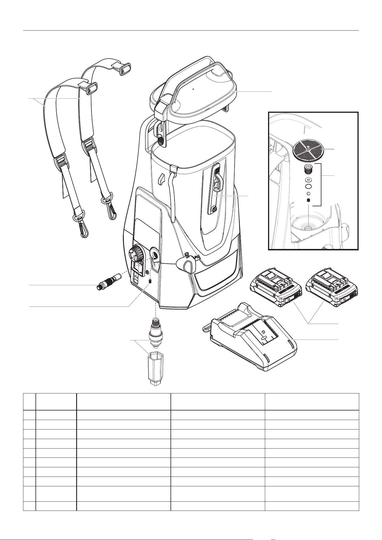
PARTS LIST • LISTE DE PIÈCES • LISTA DE PIEZAS
#
ControlMax
1650 18V Description Description Descripción
1 2463170
Strap kit Trousse de sangle
Juego de correa
2 2463215
Front strap Sangle avant
Correa delantera
3 0580072A Outlet valve assembly Ensemble de la soupape de sortie Conjunto de la válvula de salida
4 580070 Set screw Vis de pression Tornillo de ajuste
5 2463216
Tank lid Couvercle de la ré
servoir
Tapa de la tanque
6 0580662A Inlet lter Filtre d'entrée Filtro de entrada
7 580732 Inlet valve kit Trousse de la soupape d'entrée Kit de válvula de entrada
8 2463218 Battery (Bosch/AMPShare) (2) Batterie (Bosch/AMPShare) (2) Batería (Bosch/AMPShare) (2)
9 2463866 Battery charger (Bosch/AMPShare) Chargeur de batterie (Bosch/
AMPShare)
Cargador de baterías (Bosch/
AMPShare)
10 2463222 Accumulator and removal tool Accumulateur et d’outil de retrait
Accumulador y herramienta de extracción
MAIN ASSEMBLY • ENSEMBLE PRINCIPAL • MONTAJE PRINCIPAL
1
3
10
4
5
2
9
8
6
7
69
PARTS LIST • LISTE DE PIÈCES • LISTA DE PIEZAS
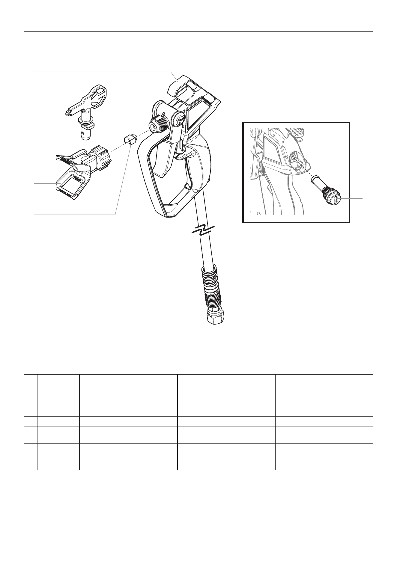
SPRAY GUN ASSEMBLY • PISTOLET DE PULVÉRISATION • PISTOLA DE ROCIADORA
1
4
2
3
5
#
ControlMax
1650 18V Description Description Descripción
1 2459729
Spray gun assembly, T2
(includes
spray hose, items 1 and 3-5)
Ensemble du pistolet de
pulvérisation,
T2
(inclut tuyau de
pulvérisation, les articles 1 et 3 á 5)
Conjunto de la pistola pulverizadora,
T2 (incluye de la manguera
pulverizadora, los elementos 1 y 3-5)
2 353-515 Spray tip, 515 Embout, 515 Boquilla de pulverización, 515
3 2443490 Spray guard assembly (includes item
4)
Ensemble anti-éclaboussure (inclut
le article 4)
Conjunto de la protección de
pulverización (incluye le elemento 4)
4 2443491 Filter and seal kit (includes item 5) Trousse de ltre et joint de l'embout
(inclut le article 5)
Juego de ltro y junta de la boquilla
(incluye le elemento 5)
5 ------ Spray lter Filtre de pulvérisation Filtro de pulverización

70
ACCESSORIES • ACCESSOIRES • ACCESORIOS
PART NO. DESCRIPTION DESCRIPTION DESCRIPCIÓN
SPRAY GUNS PISTOLETS DE PULVÉRISATION PISTOLAS DE PULVERIZACIÓN
2443489 T2 spray gun and 25’ spray hose Pistolet de pulvérisation T2 et tuyau
de 7,6 m
Pistola de pulverización de T2 y
manguera de 7,6 m
SPRAY TIPS AND ACCESSORIES EMBOUTS DE PULVÉRISATION ET
ACCESSOIRES
BOQUILLA DE ROCIADO Y
ACCESORIOS
353-211 211 ControlMax Tip Embout de ControlMax 211 Boquilla de ControlMax 211
353-311 311 ControlMax Tip Embout de ControlMax 311 Boquilla de ControlMax 311
353-313 313 ControlMax Tip Embout de ControlMax 313 Boquilla de ControlMax 313
353-413 413 ControlMax Tip Embout de ControlMax 413 Boquilla de ControlMax 413
353-515 515 ControlMax Tip Embout de ControlMax 515 Boquilla de ControlMax 515
MISC. ACCESSORIES ACCESSOIRES DIVERS ACCESORIOS VARIOS
2455514 T2 Tip Extension, 10” Rallonge d'embout T2 de 25 cm Extensión de la boquilla de 25 cm T2
2455515 T2 Tip Extension, 20” Rallonge d'embout T2 de 51 cm Extensión de la boquilla de 51 cm T2
314-482 Liquid Shield, 1 Quart Liquid Shield, 1 l Liquid Shield, 1 l
314-480 Piston Lube (8 oz) Piston Lube (236 ml) Piston Lube (236 ml)
71
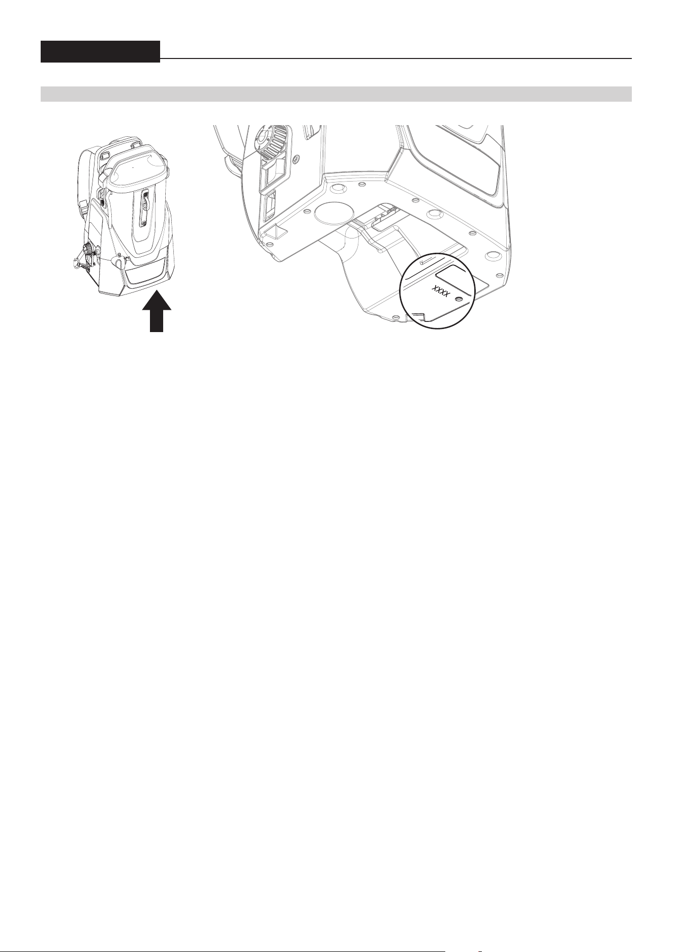
DATE CODE LOCATION • EMPLACEMENT DU CODE DE DATE • UBICACIÓN DEL CÓDIGO DE FECHA
ControlMax 1650
DATE CODE LOCATION • EMPLACEMENT DU CODE DE DATE • UBICACIÓN DEL CÓDIGO DE FECHA
Register your product online at:
Enregistrement du produit en ligne sur le site :
Regístrelo del producto en línea en:
www.titantool.com

72
ControlMax
™
1650
18V
QUESTIONS?
Call Titan Product Support at:
1-800-328-8251
Register your product online at:
www.titantool.com
BESOIN D’AIDE?
Appelez le Support de Produit Titan
1-800-328-8251
Enregistrement du produit en ligne sur le site :
www.titantool.com
¿NECESITA AYUDA?
Llame Titan Soporte de Producto al:
1-800-328-8251
Regístrelo del producto en línea en:
www.titantool.com
