Eagle Foodservice Equipment, Eagle MHC, and SpecFAB
®
are divisions of Eagle Group. ©2023 by the Eagle Group
• 100 Industrial Boulevard, Clayton, Delaware 19938-8903 U.S.A.
• Phone: 302/653-3000 • 800/441-8440 • Fax: 302/653-2065
• www.eaglegrp.com • www.eaglegrpnews.com • www.eaglemhc.com
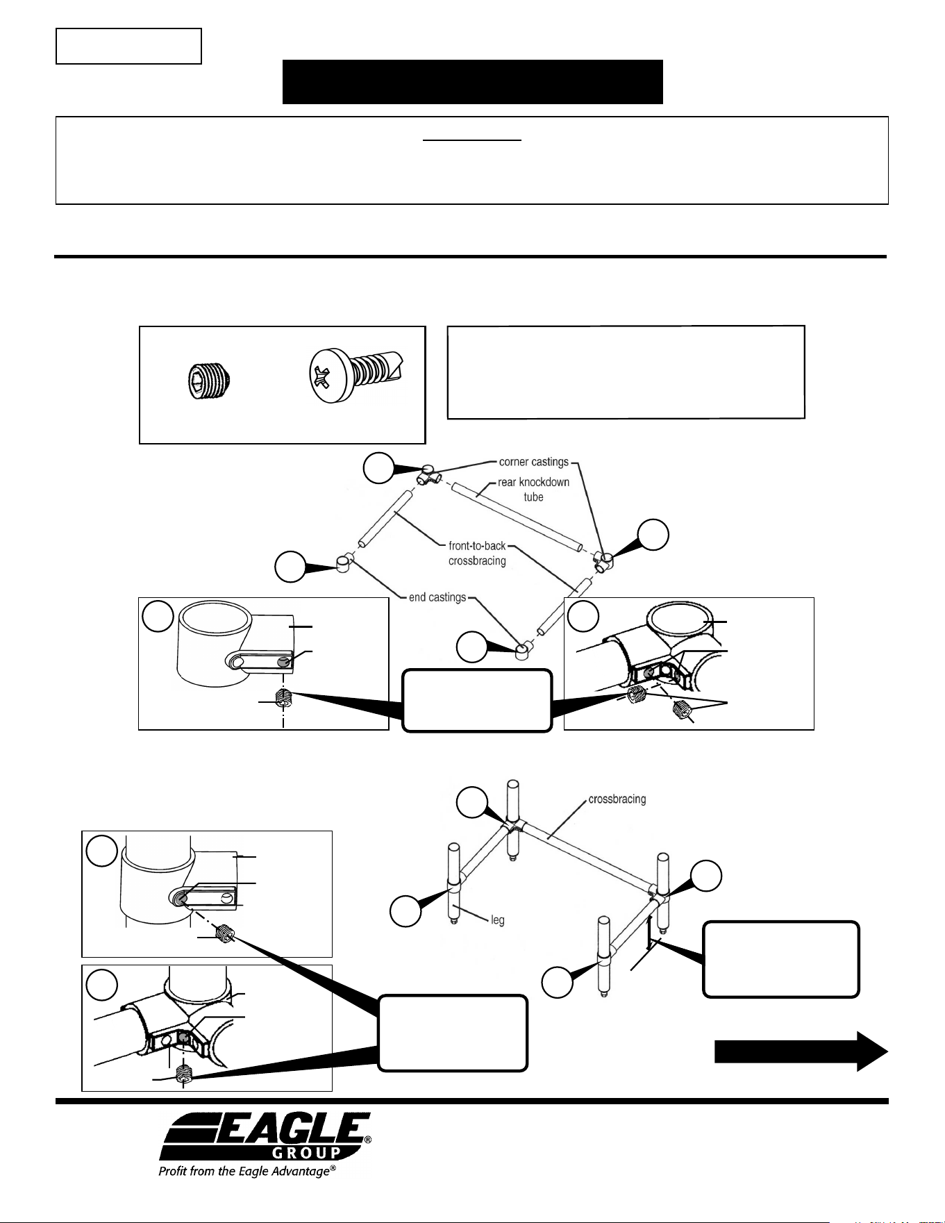
Step 2 - Attach crossbracing to legs.
• On legs, measure and mark desired height** of crossbracing.
• Insert leg through casting, stop at the mark you made.
Repeat on remaining legs and castings.
• Snug the set screws*.
EG10024 Revised 06/23
CAUTION
INSPECT CONTENTS IMMEDIATELY AND FILE CLAIM WITH DELIVERING CARRIER FOR ANY DAMAGE.
SAVE YOUR BOX AND ALL PACKING MATERIALS.
YOU ARE RESPONSIBLE FOR DAMAGE TO YOUR UNIT IF RETURNED IMPROPERLY PACKED.
(continued on next page)
ASSEMBLY INSTRUCTIONS
Spec-Bar
®
Units
INSTRUCTION SHEET
#346307
Step 1 - Assemble crossbracing.
• Tighten set screws*.
Tools required:
set *
screw
casting
threaded hole
in casting for
crossbracing
set screws*
corner casting
threaded holes
in casting for
crossbracing
1b
1a
1b
2b
2b
1a
1a
1b
set screw*
casting
threaded hole
in casting for
legs
threaded hole
in casting for
legs
* To meet NSF standards:
Set screws must be filled
with NSF-approved sealant.
set screw*
6˝
** To meet NSF standards:
Attach crossbracing at least
6˝ from the floor to the
bottom of crossbracing.
2b
2a
2a
2a
Hardware:
Thank you for your purchase. Before assembly, read these instructions carefully.
After reading, be sure to store in a safe place, should it be needed for future reference.
* To meet NSF standards:
Set screws must be filled
with NSF-approved sealant.
#8-18x1/2" screw
(quantity of 9)
5/16-18 set screw
(quantity of 4)
corner casting
• Drill
• 1/8" Drill bit
• 5/32" Allen wrench (provided)
• Phillips screwdriver
• Common screwdriver
• Clamps
NOTE: Units intended to be connected to a water supply system under pressure must be installed with adequate backflow protection to
comply with applicable federal, state and local codes. NSF International requires that a screen of at least 100 mesh shall be installed
immediately upstream of the backflow preventer. The screen shall be accessible and removable for cleaning or replacement.
Assembly is complete.
ASSEMBLY INSTRUCTIONS
Spec-Bar
®
Units
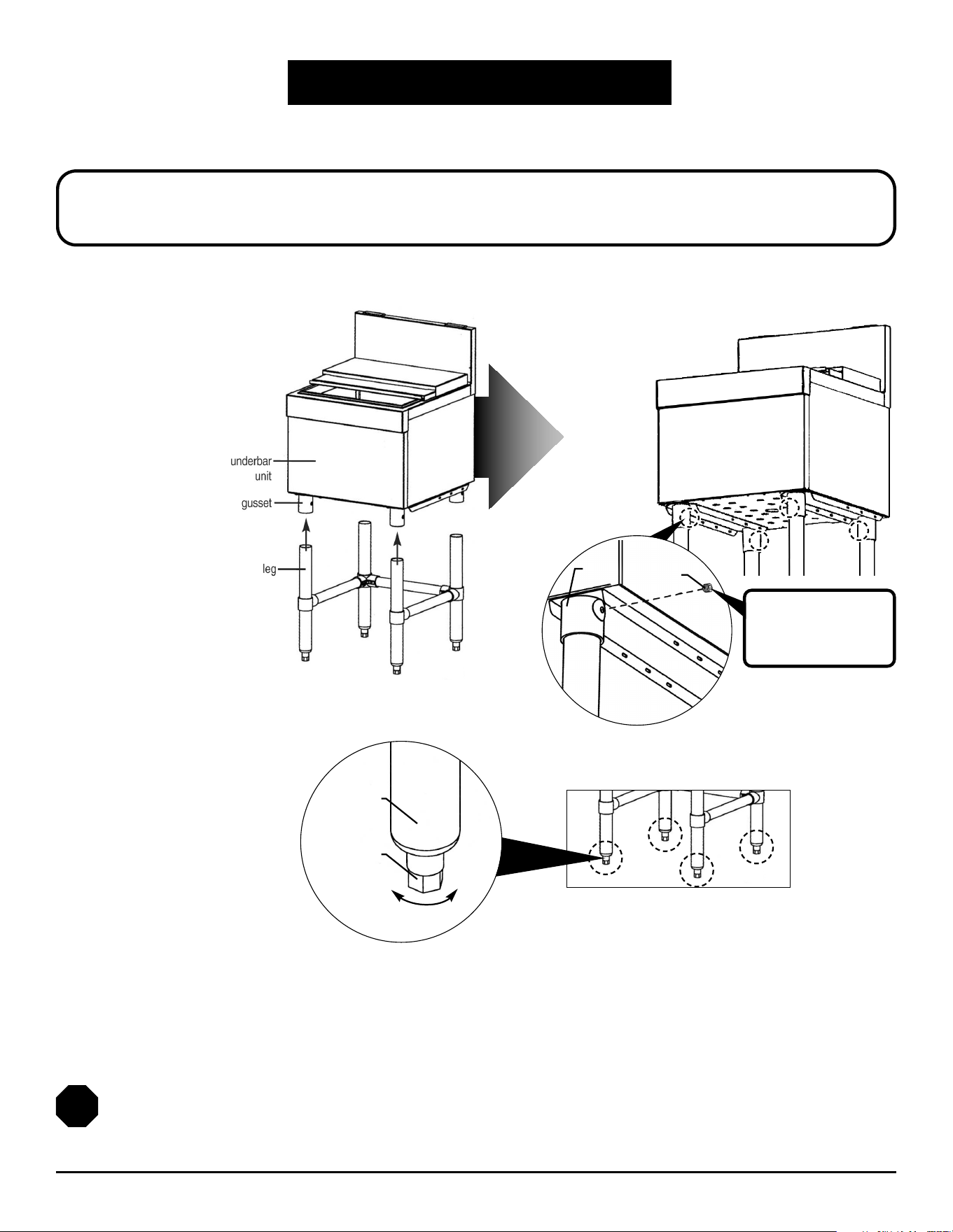
leveling foot
leg
2
• Tighten
set screws*
(one located
at each
gusset).
Step 4 - Level underbar unit.
• Adjust height of unit by turning each
leveling foot until unit is level.
(
End
)
BEFORE CONTINUING…
If joining two or more units together, skip to page 3.
set screw
gusset
* To meet NSF standards:
Set screws must be filled
with NSF-approved sealant.
Step 3 - Assemble legs
to underbar unit.
• Insert leg into each
gusset of underbar unit.
ASSEMBLY INSTRUCTIONS
Spec-Bar
®
Units
If joining two or more units together,
continue assembly by following these instructions…
3
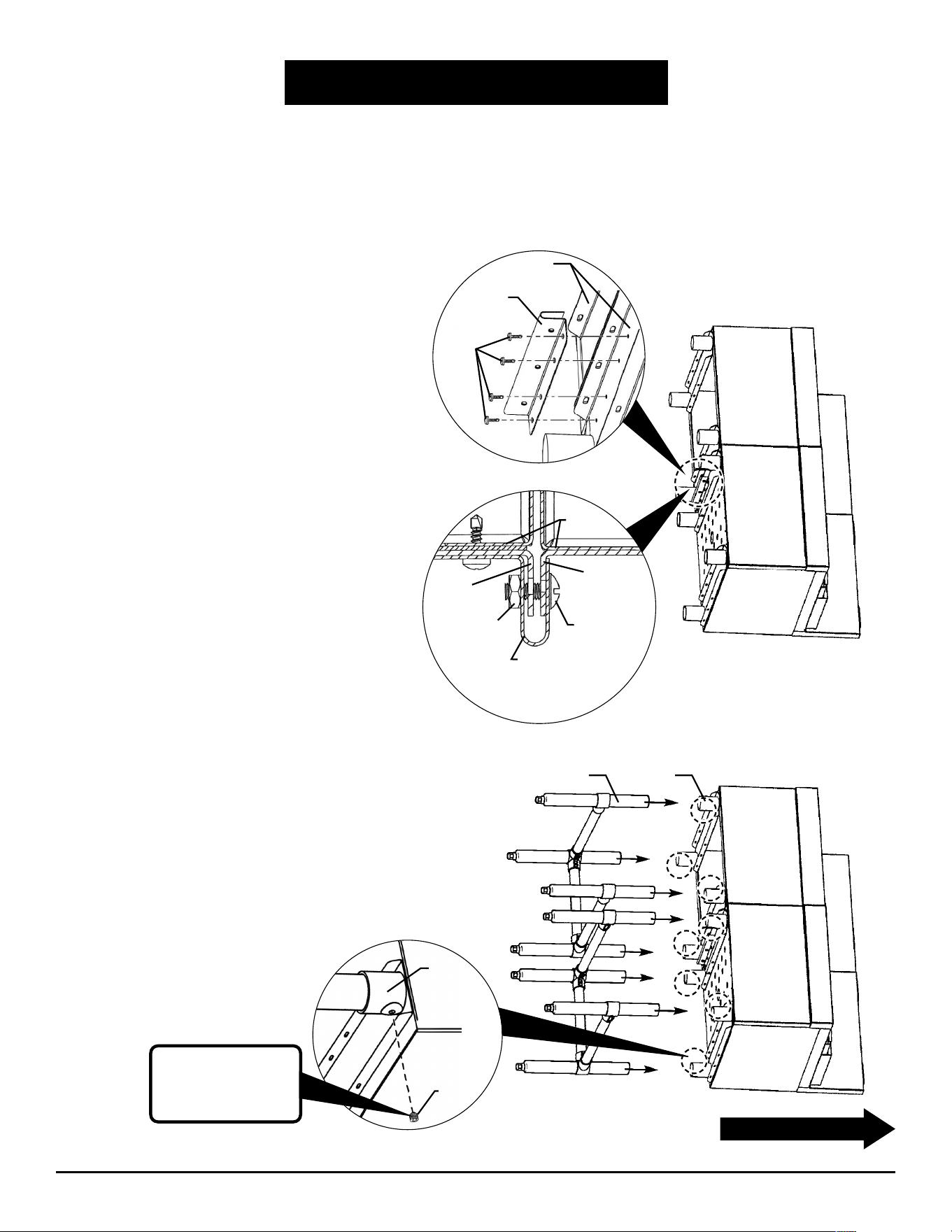
Step 3 - Attach bottom mounting plate.
• Carefully lay units onto their rear side on the floor,
side-by-side.
• At bottom of units, position bottom mounting clip
approximately midway along adjacent leg channels.
Mark and drill holes into each leg channel.
• With the #8-18x1/2" drive screws provided, affix the
bottom mounting clip to the leg channels (figure 1).
• Screw the bolts through the clip and leg channels,
and apply the nut as shown in figure 2.
figure 1
bottom
mounting
clip
drive
screws
figure 2
leg
channel
leg
channel
nut
bottom
mounting clip
bottom
of units
screw
leg
channels
(FRONT VIEW)
Step 4 - Assemble crossbracing/leg assemblies
to all underbar units.
NOTE: On each assembly, make sure the end-to-end crossbracing is at
the rear of unit, not the front.
• Insert leg into each gusset of underbar units.
• Tighten all set screws* (one located at each gusset).
• With assistance from a second person, carefully set units upright.
(continued on next page)
leg gusset
set
screw
gusset
* To meet NSF standards:
Set screws must be filled
with NSF-approved sealant.
Eagle Foodservice Equipment, Eagle MHC, and SpecFAB
®
are divisions of Eagle Group. ©2023 by the Eagle Group
• 100 Industrial Boulevard, Clayton, Delaware 19938-8903 U.S.A.
• Phone: 302/653-3000 • 800/441-8440 • Fax: 302/653-2065
• www.eaglegrp.com • www.eaglegrpnews.com • www.eaglemhc.com
ASSEMBLY INSTRUCTIONS
Spec-Bar
®
Units
LIMITED WARRANTY
Metal Masters Foodservice Equipment Co Inc. d/b/a Eagle Group or Eagle Foodservice Equipment
(“Eagle”) hereby warrants to you, the original purchaser and end-user (“you” or “your”), that the
products manufactured by Eagle that you purchased which accompany this Limited Warranty
(“products”) shall be free from defects in materials and workmanship under normal use consistent
with the accompanying documentation for a period of one year from the date of the original
installation of the equipment, not to exceed 18 months from date of shipment from Eagle. Some
exclusions apply, outlined below are the product offerings that have their own individual
warranty standards.
Warranty provided is limited to repair, replacement, or refund of the purchase price of the
affected goods. Seller shall not be liable for any indirect, special, incidental, punitive, or
consequential damages of any kind including loss of use, loss of revenue, or interruption of business.
Failure to have service work approved before work is performed shall not be covered under this
warranty. Use of an unauthorized agency will void the warranty.
The warranty covers substantiated travel expenses for up to 2 hours or 100 miles round trip up
to a maximum of $150.00. Any additional costs due to installations that require extra work, time, or
travel to gain access to service are the sole responsibility of the equipment purchaser.
Any exceptions to these travel and access limitations must be pre-approved by the factory
Service Manager.
Accessory items such as faucets, electronic eye faucets, drains, pre-rinse units are covered by a
limited warranty of 90 days, unless individual manufacturer warranty allows for additional time.
Eagle also provides individual limited warranties concerning specific product categories.
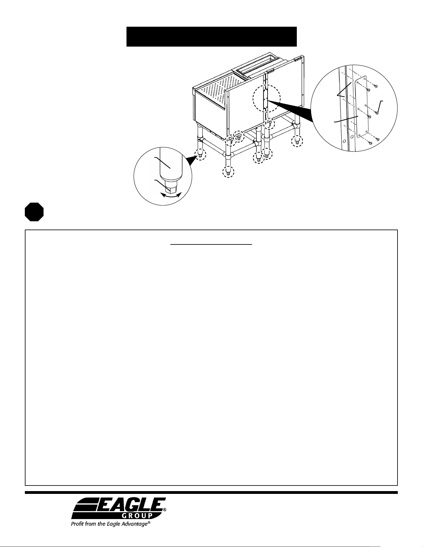
figure 4
drive
screws
back
plate
side panel
return
flanges
Step 5 - Attach back plate.
• Position back plate approximately midway along
adjacent return flanges. Mark and drill holes into
each return flange.
• Make sure the units are tightly side-by-side along
the back. A clamp (not included) can be used to pull
the units together, if necessary.
• With the drive screws provided, screw the plate and
the side panel return flanges together (figure 4).
Step 6 - Level all underbar units.
• Adjust height of units by turning each
leveling foot until all units are level.
Assembly is complete.
(
End
)
leveling
foot
leg