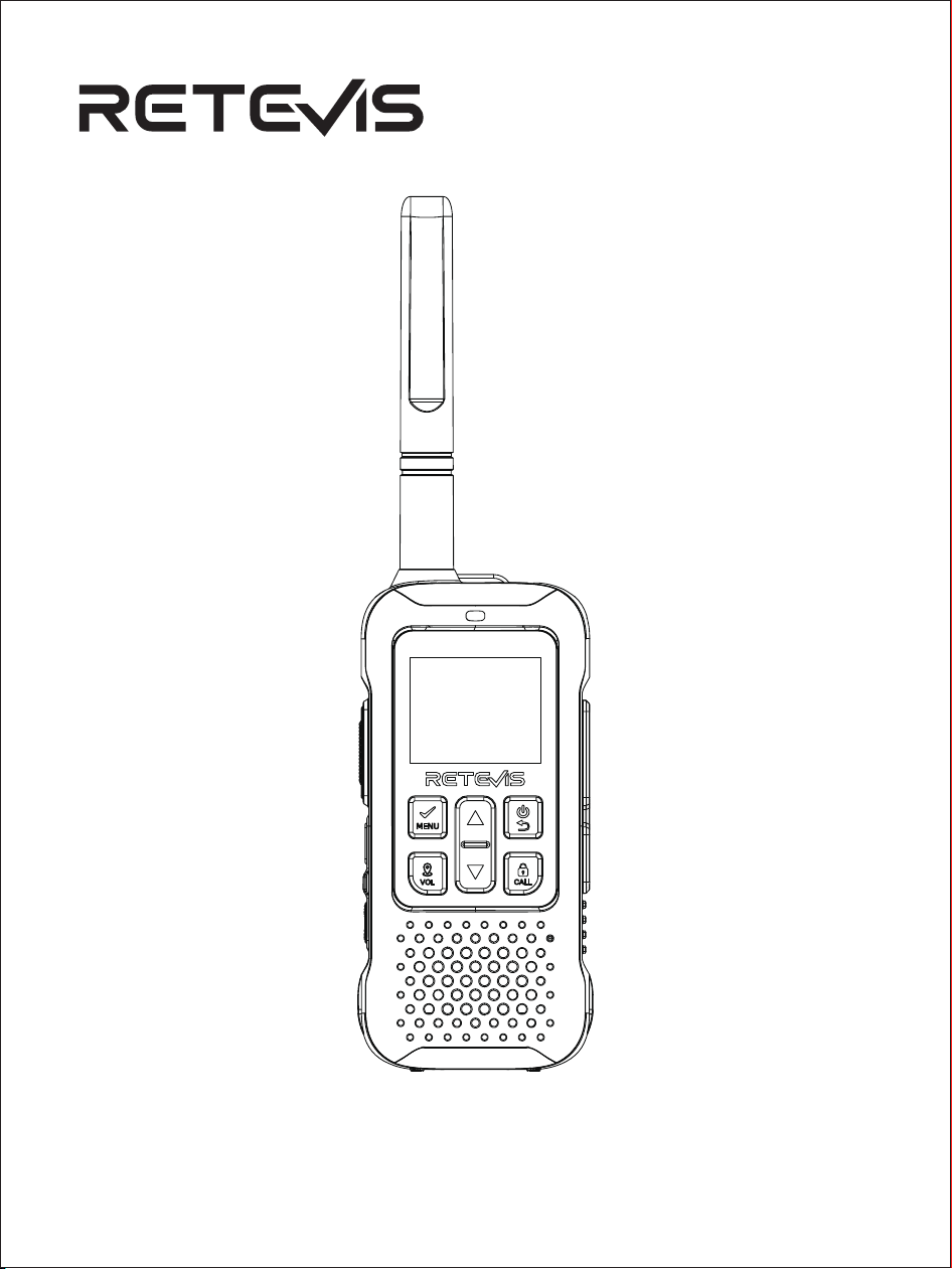
EZTalk 5
User Manual
Brochures, Software/Firmware, Manual etc, Please contact
Contents
Impoant Notice to Users ...........................................
Getting Staed ..............................................................
Screen Display.................................................................
Knowing Your Radio.......................................................
Menu Oveiew................................................................
Function Description .....................................................
Mobile App Functions ...................................................
CTCSS/DCS .....................................................................
Specications .................................................................
CAUTION ........................................................................
GUARANTEE ...................................................................
01
02
03
05
07
11
15
23
26
27
32

Impoant Notice to Users
Unboxing Inspection
Before use, please open the packaging box and carefully inspect the host unit and
included accessories. If any items are missing or damaged during transpoation, please
contact the delive personnel or dealer immediately.
Batte Information
Charging Precautions
Charge new batteries or batteries that have not been used for an extended period
before initial use. Peorming two or three charge/discharge cycles will optimize batte
capacity. When low batte power is detected, charge or replace the batte.
Compatible Batte Types
Use only batteries specied by the manufacturer. Using other batteries may cause
explosion, resulting in inju.
Note:
1. Do not sho-circuit the batte terminals or dispose of batteries in re. Do not
disassemble the batte pack casing.
2. The ambient temperature during charging should be between 0°C and 40°C. Charging
outside this range may aect proper charging.
3. Turn o the radio power during charging. Using the radio while charging may inteere
with proper batte charging.
4. Avoid unplugging the power adapter or removing the batte during the charging
process, as this may disrupt the charging program.
5. If the usage time is signicantly reduced even after a full charge, it indicates the
batte has reached the end of its life and should be replaced.
6. Do not disconnect and then reconnect a fully charged batte for additional charging,
as this may shoen batte life or cause damage.
7. Do not charge wet batteries or radios. D them with a cloth before charging to avoid
hazards.
8. Eliminating the Risk, keep away from the ammable materials,heat sources and
ignition sources while a batte is charged. Charging should only take place in a well
ventilated area and when someone is about to be aware and react to a potential issue.
9. To reduce risk of re, a batte should not be charged for more than 3 hours and
disconnect charger from line voltage (AC outlet) by removing main plug even if the
batter is not completely charged.Don't leave a device unattended while charging.
Disconnect the charger when the device is fully charged: do not overcharge the device.
Warning:
All batteries can cause damage or inju if conductive materials like jewel, keys, or
chains touch the terminals. These items can sho-circuit the batte, generating
signicant heat. Handle all batteries with care, especially when placing them in pockets,
bags, or containers with metal objects
1

Charging Procedure
1. Plug the provided adapter (standard output 5V DC) into a power outlet.
2. Place the radio with the batte installed onto the charging dock.
3. Ensure the batte contacts the charging pins correctly. The charger indicator will turn
red, indicating charging has staed. For Type-C charging, inse the Type-C plug into the
Type-C charging po on the right side of the radio. A green batte icon on the display
indicates a full charge.
4. When the charger indicator light turns green, charging is complete. You can now
remove the batte or radio for use.
Note: Do not use the radio while charging. Ensure the radio is turned o during
charging.
Maintenance and Cleaning
1. Do not hold the radio by the antenna or external microphone.
2. Wipe dust and stains from the radio with a lint-free cloth to prevent poor contact.
3. When the radio is not in use, keep the earphone jack cover closed.
4. After prolonged use, the keys, control knobs, and casing may become diy. Clean
them with a mild detergent (do not use strong corrosive chemicals) and a damp cloth.
I. Getting Staed
Installing the Antenna
1.Place the antenna onto the antenna connector and turn it clockwise to tighten.
Installing the Batte
1. Place the batte into the batte compament.
2. Tighten the two screws clockwise to close the batte cover securely.
Note: Tighten all screws when installing the batte to ensure waterproof peormance.
Radio Batte Level
1. Full batte bars【 】indicate sucient power. When the batte indicator
【 】shows zero bars, the device enters low-batte mode, issuing warnings via a
low-batte ale tone and a batte icon.
Power On/O
1. Press and hold the【 】key to turn the radio on or o.
Volume Adjustment
1. In standby mode, briey press the【 】key to enter the volume adjustment
inteace. Use the Up“ ”and Down“ ”keys to adjust the volume level.
Making a Call
1. For communication, all radios in your group must be set to the same channel
frequency and sub-tone code.
2. During a call, the transmitting radio should press and hold the [PTT] key to speak.
2
The screen will display "A BAND TX" or "B BAND TX", and the red LED will light up.
Simultaneously, the receiving radio's screen will display "A BAND RX" or "B BAND RX",
and the green LED will light up. For optimal call quality, hold the microphone 3-5 cm
from your mouth while speaking.
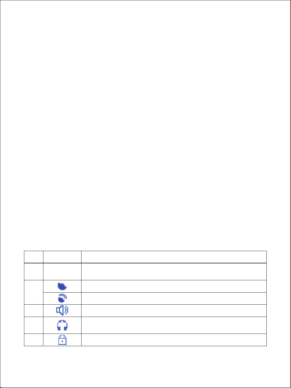
II. Screen Display
3
NO.
1
Signal Strength. Indicates current signal level for judging
communication quality.
Icon/Text Description
4
Headset. When a headset is plugged in, audio automatically
switches to headset output.
3 Speaker. Indicates audio is being received/output.
2
GNSS enabled, scanning for satellites.
Successfully connected to one or more satellites.
5 Keypad Lock. Indicates all keys except PTT and SOS are locked.
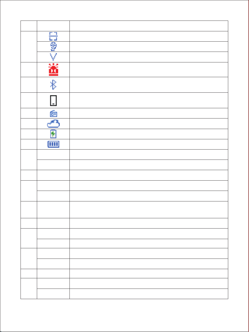
4
NO. Icon/Text Description
11 NOAA Weather Ale Icon
12 Charging Icon. Red lightning: Charging. Green: Fully charged.
13 Batte Level Icon
15 Channel Number within the current Zone.
14
+
C1
18 Channel Number.CH25
21 Type:CTC\DCS\DCSICTC
"+": Transmit frequency > Receive frequency.
-
"-": Transmit frequency < Receive frequency.
16
Z1 Zone Number. "Zx": Represents the x-th zone in the zone list.
ALL "ALL": All Channels mode.
19
FR "FR": Reverse Frequency.
TA "TA": Talk Around.
20
L "L":Low Power
H "H":High Power
22
W “W”:Wide (25KHz)
N “N”:Narrow (12.5KHz)
17 Frequency
Channel Information Display Area (Frequency, Channel Number,
Channel Name).
6
Scanning enabled, radio scans between added channels.
Monitor mode enabled, receives all trac on the current channel.
10 FM Radio. Enabled, receiving or broadcasting FM audio.
7
Alarm. Activated by the alarm key, emits an alarm sound or
sends an emergency signal.
8
Bluetooth Connection Status. Blue: Connected.
Black: Not connected.
Voice Operated Transmit (VOX) is activated.
9
Bluetooth Phone Connection. Blue: Connected to phone.
Black: Not connected.
5
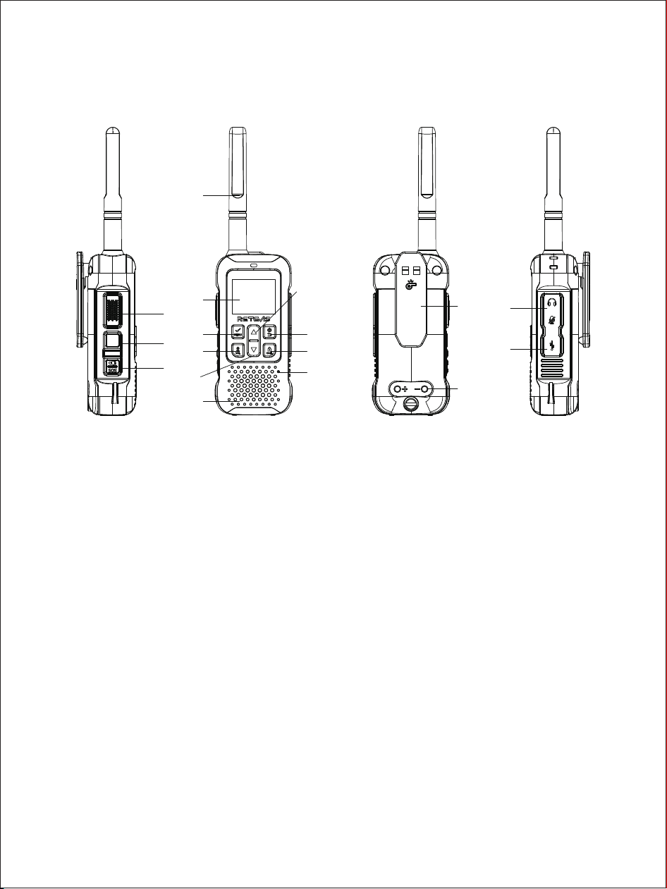
III. Knowing Your Radio
1. PPT KEY
2. Side key 1
3. SOS/Flashlight
4. Menu/Conrm Key
5. VOL/LOC Key
6. Up/Channel+ Key
7. Back/Power O Key
8. CALL/Key Lock
9. Down/Channel- Key
10. LCD display
11. Speaker
12. MIC
13. Antenna
14. Belt clip
15. Desktop charging po
16. Earphone Jack
17. Type-C Charging/Data Po
1
13
4
10
6
14
16
17
15
7
8
12
5
9
11
2
3

6
Key Functions
1. 【PTT】Key (Push-To-Talk)
Press and hold to transmit; speak into the microphone. Release to receive.
2.【 】K1Key (Programmable)
Default: Sho Press = Scan On/O; Long Press = VOX On/O.
Customizable via Menu: O, Scan, Power Level (H/L), Monitor, VOX, Talk Around, Reverse,
A/BBand, One-Key CTCSS/DCS O .
3. SOS/Flashlight
Long Press: Activate emergency alarm. Sho Press (during alarm): Cancel alarm. Sho
Press (normal): Toggle ashlight on/o.
4.【 】Menu/Conrm Key
Sho Press (Standby): Enter main menu. Sho Press (in Menu): Conrm selection.
5.【 】VOL/LOC Key
Sho Press (Standby): Enter volume setting. Long Press (Standby): Location function
(e.g., send location).
6.【 】“Up/Channel+ Key”
Sho Press (Standby): Cycle up through channels/frequencies. Sho Press (Menu): Cycle
up through menu options.
7.【 】Back/Power O Key
Sho Press: Return to previous menu level. Long Press: Power the radio On/O.
A/BBand、WeatherAlerm
8.【 】CALL Key/Lock Key
Sho Press (Standby): Send Call Tone. Long Press (Standby): Toggle Keypad Lock (locks
all keys except PTT & SOS). Long press again to unlock.
9.【 】“Down/Channel- Key”
Sho Press (Standby): Cycle down through channels/frequencies.
Sho Press (Menu): Cycle down through menu options.
7
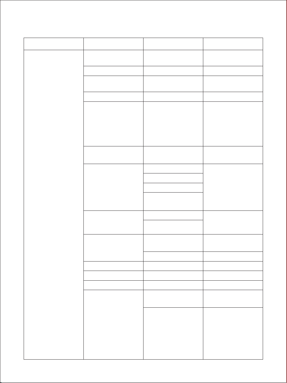
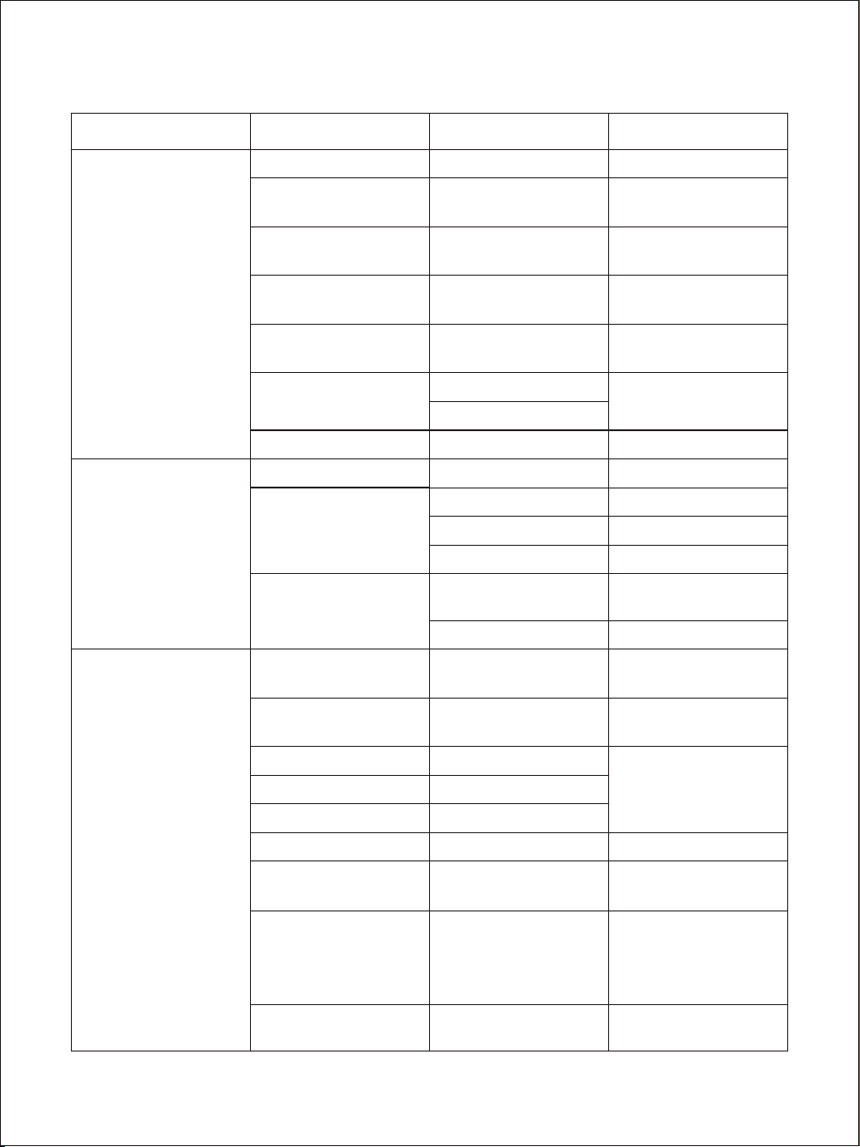
IV. Menu Oveiew
Main Menu Sub-menu Sub-submenu Description
Main Set
Display Mode /
Frequency, Name,
Channel Number
Back Light Time /
Always On(0)、3s、
6s、9s、12s、15s、
18s、21s、24s、
27s、30s、
1min、2min、3min、
4min、5min
Band /
Single/Dual Watch,
A/B Band Switch
Squelch / 0 = Squelch Open
VOX Switch /
VOX On/O
VOX Delay / 500ms、1s、1.5s、2s
VOX Level /
Sensitivity Level 1-9
Back Light Level / Level 1-5
Key Function
SK1 Sho Press Customize SK1 Sho
Press/Long Press
Action
SK1 Long Press
Power Save
Power Save Level
Power Save Level
(1�1,1�2,1�4,OFF)
Delay before Power
Save:5s、10s、15s、
20s、25s、30s、
1min、3min、5min、
10min、15min、
20min、25min and
30min。
Power Save Delay
Audio
Audio Enable
Mic Gain Microphone Gain (0-5)
TX Tone, Key Beep,
Roger Beep
GNSS
GNSS
GNSS Info
Share Position
List Information
GPS On/O、GPS
Mode Selection、
GPS Positioning
Information、Share
Location、GPS
Message Receive List
Call Light /
Screen On for
Incoming Call
8
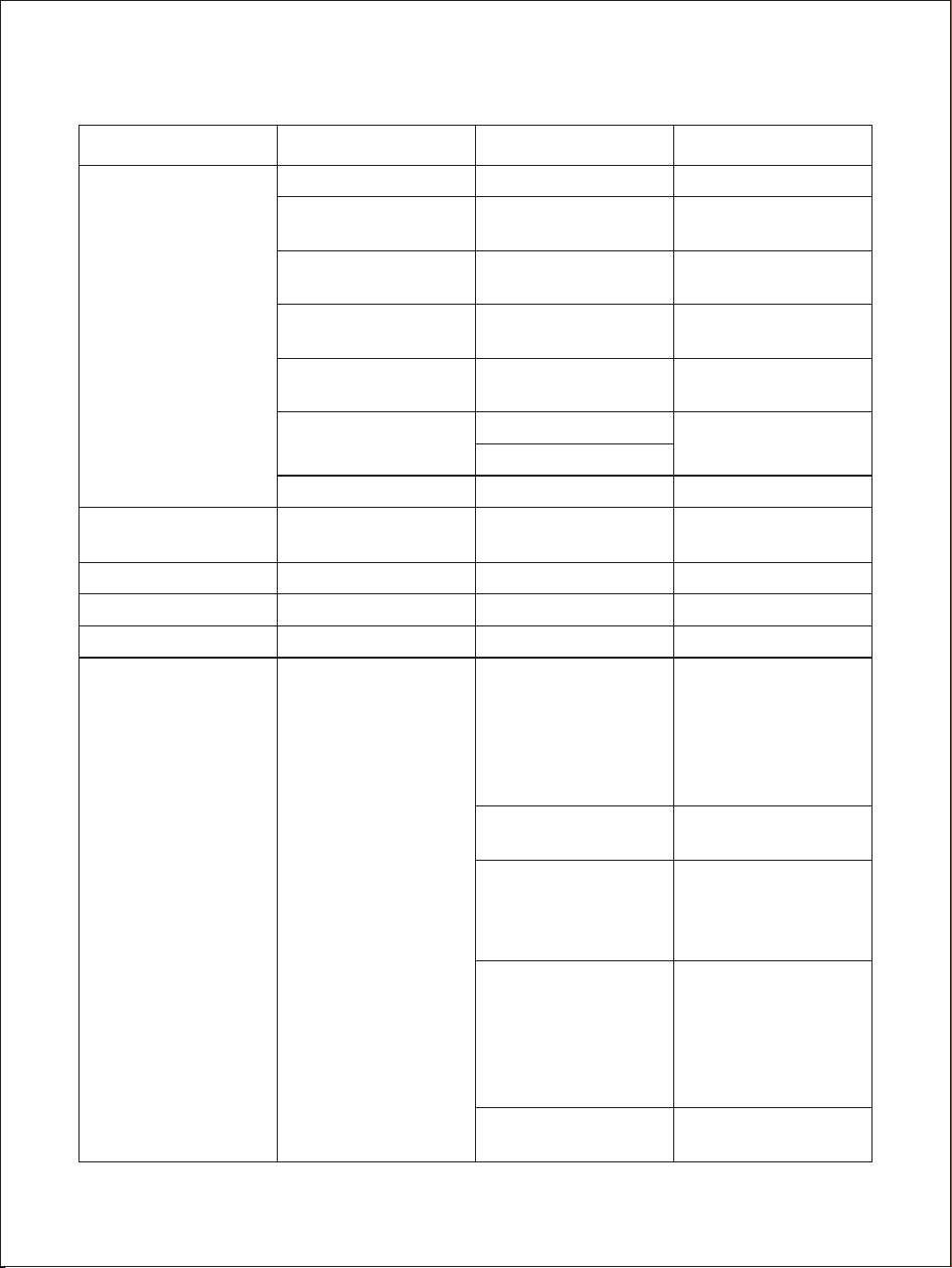
Main Menu
Sub-menu Sub-submenu Description
Main Set
Zone
Channel
Low Batte Alarm /
Low Batte Ale
Setting
Single Tone /
1000Hz、1450 Hz、
1750 Hz、2100 Hz
Work AloneTime /
O、5min、10min…
55min、60min
TOT Again Time /
O、5s、10s、15s、
20s、25s、30s
Menu Timeout / Auto-exit Menu Time
Radio Information / Radio Info
Channel Info /
Specic Channel
Parameters
Bandwidth /
Wide 25KHz,
Narrow 12.5KHz
C-CDC /
Multiple CTCSS/
DCS Options
R-CDC /
T-CDC /
TX Power /
High, Low
TxOutTime /
Innite、5~300
seconds
TxPermit /
Always Allow、
Receive Only、
Channel Free、
CTC/DCS Mismatching
Talkaround & Reversal /
Talk Around、
Reversal、Close
All Channels Select Zone Select All Zones
Zone_xxx
Select Zone Select Specic Zone
+Add Zone+
Edit Channel
Edit Channels in Zone
Delete Zone
Add Zone CH
Save Zone
Delete Specic Zone
Add Channels to
New Zone
Save Zone Information
All CTCDC Switch
ALL CTC Open
Enable/Disable All
Channel CTCSS/DCS
ALL CTC Close
9
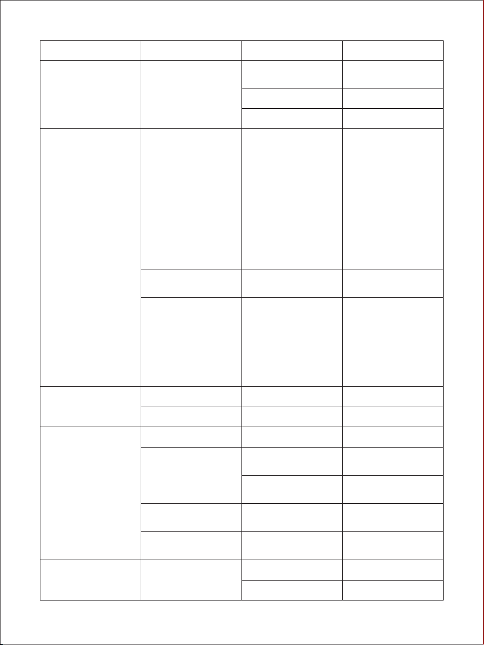
Main Menu
Sub-menu Sub-submenu Description
Main Set
Volume
Low Batte Alarm /
Low Batte Ale
Setting
Scan Mode
Scan Mode Carrier,
Time, Search
Priority Channel 1
Preferred Scan
Channel 1 Setting
TX Mode Set
TX Mode Set:
Selected、Last Active
Channel、Designated
Channel
Designated Channel
Designated Channel
Selection—used
when the
transmission mode is
set to “Designated
Channel.”
Single Tone /
1000Hz、1450 Hz、
1750 Hz、2100 Hz
Work AloneTime /
O、5min、10min…
55min、60min
TOT Again Time /
O、5s、10s、15s、
20s、25s、30s
Menu Timeout / Auto-exit Menu Time
Radio Information / Radio Info
Volume Set /
Volume Level 0-7
(0=Mute)
FM Radio
FM Radio / FM Radio Function
Call Tone
Tone / 10 Call Tone Options
Siganling
PTT ID /
Select All Zones
Scan
Channel Scan Set
Scan Condition
Scan Criteria: Carrier
or CTCSS/DCS.
When set to Carrier,
the radio will not
check for sub-audio
tones.
All CTCDC Switch
ALL CTC Open
Enable/Disable All
Channel CTCSS/DCS
ALL CTC Close
10
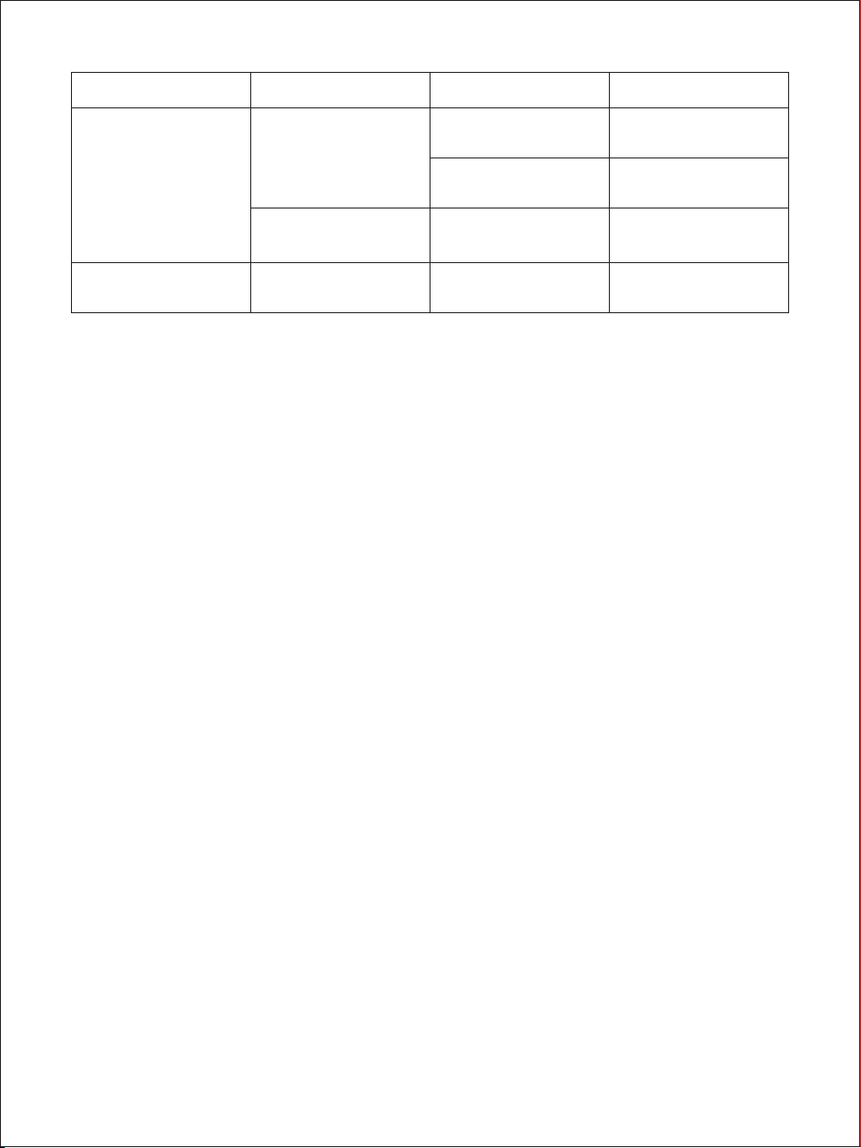
Main Menu
Sub-menu Sub-submenu Description
Priority Channel 2
Preferred Scan
Channel 2 Setting
/Alarm Mode
Alarm Mode: Local
Alarm, Remote Alarm
Channel List Display of Scan List
Hang time 1 to 16 seconds
/
Weather Alarm Switch
BT APP Talk
Bluetooth Call -
App Mode
/
Weather Alarm
NOAA Channel List
Weather
CH01-CH12
Whole machine clon Full Clone
Basic set Clone
CLON_TX
Radio Clone
Basic Settings Clone
/ Bluetooth Switch
BT Earphone
BT Power
BT SPK Gain
BT SPK Gain
BT Call
Bluetooth
Bluetooth Call -
Headset Mode
/
Bluetooth Speaker
Gain
/
Bluetooth
Microphone Gain
Scan Channel Scan Set
Emergency
Alarm Channel Type /
Alarm channel type
selection: Current
channel, Designated
channel. Upon
selecting
'Designated
channel', alarms will
be sent via the
channel chosen in
the 'Designated
Channel' menu.
Designated Channel /
Specied Alarm
Channel Selection:
Applicable when the
alarm transmission
type is set to
"Designated
Channel".
11
Main Menu
Sub-menu Sub-submenu Description
Channel Clone
Channel Settings
Clone
//Facto Reset
Restore Facto
Defaults
Basic set & Channel
CLON_TX
Radio Clone
Basic & Channel
Settings Clone
/
CLON_RX
Receive Clone
Settings
V. Function Description
1.Bandwidth Selection
Wideband communication delivers superior audio clarity, making it ideal for scenarios
demanding high communication quality. In contrast, narrowband communication
consees frequency resources, making it more suitable for multi-user environments,
albeit with a slight reduction in audio quality. Channels 8 to 14 are xed in narrowband,
while all other channels default to wideband, with adjustable bandwidth settings
permitted.
2.Power Switching
Channels 8 to 14 are hard-set to low power, while all other channels default to high
power (user-adjustable). The power level (High/Low) for adjustable channels can be
congured via the "Power" menu option.
3.Dual Watch
The Dual Watch function allows the walkie-talkie to monitor two preset channels. It
automatically and rapidly scans between these two channels, ensuring that the user
does not miss any calls on either one.
4.Talkaround & Reverse Frequency
When the Talkaround function is activated, the radio's transmit frequency becomes
identical to its receive frequency, and its transmit signaling code changes to match the
received signaling code. This enables direct unit-to-unit communication when the
repeater is unavailable or bypassed.
5.Tone Signaling
This function is used to awaken the repeater from its standby mode. From the standby
screen, simultaneously press and hold the [PTT] and [SK1] keys to enter transmission
mode. Release either side key ([SK1]) to resume normal voice transmission.
6.Local Alarm
Only this unit will sound an audible alarm. Press and hold the SOS key to initiate the
alarm. Press the SOS key sholy to cancel it.

12
7.Remote Alarm
The unit will sound an audible alarm and simultaneously broadcast the alarm signal over
the pre-set channel. Press and hold the SOS key to activate the alarm. Press the SOS key
sholy to deactivate it.
8.Lone Worker
This is a safety monitoring feature. If no operation is detected within the set time, the
radio will issue a cancellation prompt and sound a warning tone for 15 seconds. If not
cancelled during this period, it will automatically enter the alarm mode. This function can
be congured via the menu or the programming software.
9 .VOX
When enabled, this feature allows transmission to be initiated by voice without pressing
the PTT button. The VOX sensitivity is congurable across multiple levels. A higher level
corresponds to greater sensitivity, requiring a lower voice volume to activate. Sensitivity
Level: Adjustable range 1-9 (Default: 5); VOX Delay: Adjustable range 500-2000 ms
(Default: 1000 ms)
10.Squelch Level
The squelch level, which mutes the receiver audio when no valid signal is present, is
adjustable from levels 0 to 9 (Default: 3). Level 0 sets the squelch to be permanently
open.
11.Roger Beep
This function can be enabled or disabled via the menu. When activated, a tone is sent to
the receiving pay upon releasing the PTT key, signaling the end of your transmission.
12.Microphone Gain
This setting adjusts the sensitivity of the walkie-talkie's microphone by controlling its
input level. Increasing the gain makes the microphone more sensitive to quieter sounds,
resulting in a higher output volume, while decreasing it reduces sensitivity for louder
environments.
13.Power Saving Mode
To consee batte power and extend standby time, the radio will enter a power-saving
cycle (alternating between sleep and active periods) after a period of no transmission,
reception, or button operation. The duty cycle can be set to: OFF, 1�1, 1�2, 1�4. Default:
1�4.
14.Power Saving Mode Delay
Sets the delay time before the radio enters power saving mode when no operation is
detected. Congurable options: 5s, 10s, 15s, 20s, 25s, 30s, 1min, 3min, 5min, 10min,
15min, 20min, 25min, 30min. Default: 10s.
15.TOT
The TOT function is a transmission time limiter designed to prevent prolonged single
transmissions from occupying the channel. When the PTT button is pressed, an internal

13
timer stas. If the transmission duration reaches the preset time limit (e.g., 180 seconds),
the radio will automatically cut the transmission signal, emit a warning tone, and return
to receive mode.
16.TOT Again Time
This setting denes the time delay required before transmission is permitted again after
a Time-Out Timer (TOT) cuto. Available options: OFF, 5S, 10S, 15S, 20S, 25S, 30S.
Default: OFF.
17.Global CTCSS/DCS Setting
This function enables or disables all sub-audible tones (CTCSS/DCS) globally. When set
to "O", the tone squelch function is deactivated on all channels. When set to "On", all
channels reve to their original, individually programmed CTCSS/DCS states.
18.Side Key Customization
The "SK1 Sho Press" and "SK1 Long Press" actions can be assigned to the following
functions: O, Power Switch, Monitor, Scan, VOX On/O, Talkaround/Reverse Frequency,
Dual Watch Switch, DCS, NOAA Weather Ale.
19.Monitor
The Monitor function temporarily lowers the squelch level of the current channel. This
allows you to hear weak radio signals (below the normal squelch threshold) or signals
that do not car the correct CTCSS/DCS code.
To use it, assign the "Monitor Switch" to a programmable key via the menu or program
ming software. On the standby screen, press this customized monitor key to activate the
function (the monitor icon will illuminate), enabling the radio to monitor the prima
standby channel.
20.Low Batte Alarm
When the batte level becomes critically low, the unit will periodically emit a low batte
warning tone. If the voice prompt feature is enabled, an audible voice ale will also be
announced.
21.Scan
Assign the "Scan Switch" function to a side key via the menu or the programming
software. On the standby screen, press this customized scan key to activate the function
(the scan icon will illuminate). The radio will then begin scanning from the prima
standby channel. The scan parameters are congurable via both the menu and the
programming software.
22.Wireless Clone
This feature transfers parameters (e.g., frequency, CTCSS/DCS codes, channels) from a
master radio to a slave radio via radio waves (without cables).
In the Radio Clon menu, the slave device selects the CLON_RX option to enter the
innite cloning reception inteace. The master device selects the CLON_TX option,
chooses the data type to be cloned as needed, and nally presses the conrm key to
enter the transmission inteace and begin data transfer.

14
The receiver restas automatically if no data is received.
The transmitter restas automatically if no slave response is detected.
23.Restore Facto Settings
A conrmation prompt will appear after three consecutive conrmations. Once
conrmed, the device will restore facto settings and reboot. The process can be
cancelled at any time before the restoration begins. All radio information will be reset to
facto defaults.
24.Channel Capacity
This radio suppos up to 99 channels. Channels can be added, deleted, or edited via the
programming software.
25.Sub-audible Tones
In addition to the standard set of sub-audible tones, the radio suppos multiple custom
analog (CTCSS) and digital (DCS) tones, which can be set via the programming software.
”C-CDC”:Sets both the receive and transmit tones simultaneously.
”R-CDC”:Sets the receive tone only.
”T-CDC”:Sets the transmit tone only.
26.PPT ID
Each device has a unique PPT ID, which is the individual number for the walkie-talkie
and can be set on the CPS/host/app.
27.Alias
The alias of the walkie-talkie can be modied through the App or CPS, while the host
can only view it.
28.Tail Tone Elimination
The "click" sound at the end of a relay can be eliminated through settings in the frequen-
cy-writing software, which is enabled by default.
29.NOAA
Weather Ale Switch:
The Weather Alarm function can be enabled or disabled under the "Weather Alarm"
option in the "Weather" menu.
Weather Ale Channel Selection:
Under the "NOAA Channel List" in the "Weather" menu, you can enable monitoring of
NOAA channels. Use the Up/Down keys to switch between the channels being moni-
tored.
30.Bluetooth
The Bluetooth function enables wireless audio transmission and data exchange, allowing
pairing with devices such as Bluetooth headsets, headphones, and smaphones.
Parameters can be congured via a mobile app connected through Bluetooth.
a.Press the MENU button to enter the menu inteace. Navigate to the "Bluetooth"
option. Press MENU again to access the Bluetooth submenu.

15
b.Select "BT Power" from the menu. Press the MENU button to congure the Bluetooth
power switch.
31.Bluetooth Headset Pairing
For the initial connection, rst set your Bluetooth headset to pairing mode, then open
the "Bluetooth Headset Scan" option in the device menu.
1. Press the MENU button to enter the menu inteace. Navigate to and select the
"Bluetooth" option. Press MENU again to enter the Bluetooth submenu.
2. Select"BT Call", then press theMENUbutton to enter the submenu.
3. Press theMENUbutton to select"BT Earphone".
4. Press theMENUbutton to select"EAR Scan".
5. Press theMENUbutton to conrm. The device will enter Bluetooth headset scanning
mode. Upon successful scanning, it will automatically navigate to the"EAR Scan List"
inteace. If no device is found, check whether a Bluetooth headset is available or resta
the scanning process.
6. Enter the"EAR Scan List"inteace, select a Bluetooth device, and press theMENU
button to initiate pairing.
7. Once successfully connected, the Bluetooth headset icon in the status bar will turn
blue.
VI. Mobile App Functions
Radio Parameter Settings
a.Open the mobile app. Tap "Add Radios" on the screen or the "+" icon in the upper-right
corner. The inteace will then proceed to the corresponding submenu.

16
b.Tap the "EZTALK5" option to sta scanning. After scanning completes, select the target
device from the list. Tap the "Add Device" button. Upon successful connection, the
inteace will automatically return to the app home screen. The phone icon in the radio's
status bar will now turn blue, indicating an active connection.
c.On the app home screen, tap"Read Data"to initiate data reading.
d.After tapping, the inteace will display"Reading Data", indicating that data is being
read.
e.After the reading is complete, enter the radio parameter settings inteace, where
parameters can be congured as needed.
f.After completing the settings, tap the"Write Data"button to write the parameters.
g.The inteace will display a"Writing Data"progress bar.
h.After successful writing, the inteace displays"Finished writing", indicating the
process is complete.
i.After the app setup is complete, the device will resta to update the data.
17
Retevis App MAP Function
The MAP function in the Retevis mobile app is a versatile software solution designed for
outdoor teams. It integrates features such as team creation, location tracking, naviga-
tion, electronic fencing, hand-drawn maps, and emergency ales. Users can create
teams and track members' locations in real time to ensure safety. The app suppos
setting up electronic fences to monitor whether team members enter or leave specic
areas, and provides an emergency ale function for quick assistance.
* Only after two paies have communicated via PTT will the system automatically
recognize them as teammates, allowing them to be added to your team.
Options Images Details
Main
Inteace
1."Reconnect" indicates your current
walkie-talkie connection status.
If not connected, it prompts:
"Bluetooth connection failed, please
check whether the walkie-talkie
"BT APP Talk" is turned on, calls
initiated via the app are connected
successfully."
2.Team Settings: Enter the team
settings inteace to congure your
team's information.
3.Map Layer: Switch between
Default or Satellite map display.
4.Tools: In the tools inteace, you
can set Drawn Track, Send SOS,
and Geofence.
5.Map Main Inteace: Displays
current map information. If in a
team, it shows teammates'
locations.
6.Current Position: Switch to your
current location.
7.Map Zoom In: Magnify map
details.
8.Map Zoom Out: Reduce map
details.
Navigation: Select a location for
navigation or use hand-drawn
tracks for navigation.
Reconnect
Team Settings
Layers
Tools
Zoom In
Zoom Out
Navigation
Current Location

18
Team Settings
Team
Settings
Tap the icon on the right side
of the main inteace
1. Display team member names:
When enabled, the name of each
team member will be displayed on
the map, aiding in quick
identication of individuals within
the team.
2. Display last location time:
When enabled, the map will show
the timestamp of the last location
update for each team member.
3. Player historical positions
displayed:
This feature displays the historical
positions of team members,
allowing users to review their
movement tracks over a past period.
4. Select a team:
Users can either create a new team
or select an existing one from
multiple teams. Once a team is
selected, the locations, historical
tracks, and other relevant
information of its members will be
displayed.
Team List
1. Click on “Select a team”
2. The Load function is used only
to lter and display teams.
Load: The map displays the current
locations of all team members by
default.
Loaded: The map displays only the
current locations and movement
tracks of the selected team
members. Other team members are
hidden.
In the app or CPS, you'd better
update both your alias and PTT ID
so that your radio can be identied
when teaming up.
*Only one team can be selected at
a time.
*You can only create a team after
communicating via PTT with the
team leader.
19
Team Settings
Layer Display
Create a
team
On the "Team List" inteace, tap
the "+" button on the right to create
a new team.
1.Tap "Click to Add Team Avatar" to
select a prole picture for your
team.
2.Tap "Add Team Name" to enter
your team's name.
3.Tap "Add Members" to add
members to your team.
*How to select members:
(1) The radio is in the Bluetooth
menu with the BT Call → BT APP
Talk function enabled.
(2) The radio that need to be
connected must be on the same
frequency, and the team members
must press the PTT button to send
their GPS location to the group
leader.
Layer
Settings
On the main inteace, tap
the icon on the right
1. You can choose to display the
map in "Default" mode or
"Satellite" mode.
20
Navigation
Tools
Select
navigation
method
Tap the "Navigation" button on the
main inteace.
"Set Destination" – Select a location
for point-to-point navigation:
1.Tap the "Set Destination" option,
then select your desired destination
on the map. The latitude, longitude,
and address information of the
location will be displayed.
2.Tap "Sta Navigation" to
automatically redirect to a
third-pay map application for
navigation.
"Select Track" – Choose a specied
route for navigation:
1.Tap the "Select Track" option,
then select a present track from the
"Drawn List" to begin navigation.
Tools
On the main inteace, tap the
“ ”"Tools" icon on the right to
enter the Tools settings page.
1.Drawn Track: Allows you to
manually draw a route or path on
the map, which can then be used as
a reference for navigation.
2.Send SOS: Enables sending your
current location to your team
members.
3.Geofence (Electronic Fence): Lets
you dene a specic area or
bounda on the map. The system
will trigger a notication when a
device or user enters or exits this
designated area.
21
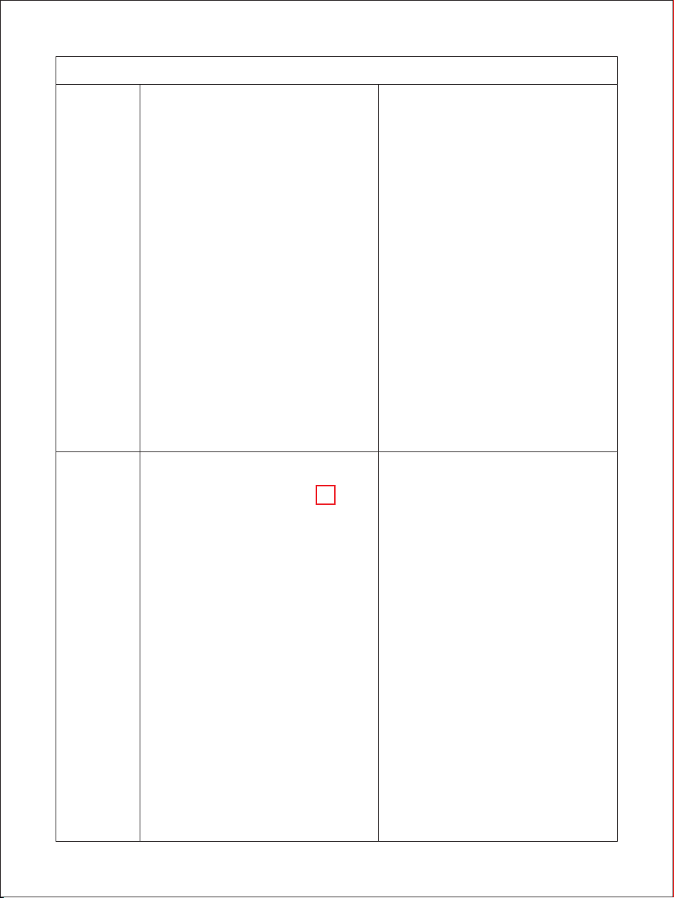
Tools
Drawn
Track
Tap the "Drawn Track" button in the
"Tools" menu.
1.The "Drawn List" will display your
list of previously hand-drawn tracks.
Tap any track in the list to view its
detailed information. Press and hold
a track to delete it.
If there are no tracks in the "Drawn
List", tap the "+" button at the
bottom to create a new one.
Add Drawn
Track
Tap the "+" button at the bottom of
the "Drawn List" inteace to create a
new hand-drawn track.
1.While drawing the track, tap the
"+" button on the inteace to add a
new waypoint. Then, drag the red
position marker on the map to
select your desired next point. Tap
the "+" button again to add
subsequent waypoints, gradually
building your complete track.
2.During the drawing process, you
can tap the "<" (undo) button to
remove the last added waypoint.
Once the track is complete, tap the
save button on the right to save it.
You will be prompted to name your
hand-drawn track, and it will then
be stored in the "Drawn List".
22
Tools
Geofence
Tap the "Geofence" button in the
"Tools" menu.
1.The "Geofence List" will display
your existing geofences. Tap any
ent in the list to modify its
parameters. Press and hold a
geofence to delete it.
2.Use the toggle switch on the right
side of each geofence ent to
activate or deactivate it. Please note
that only one geofence can be
active at a time.
Tap the "+" button at the bottom of
the "Geofence List" to create a new
geofence.
Add
Geofence
Tap the "+" button at the bottom of
the "Geofence List" to create a new
Geofence.
1.Geofence Name: Set a name for
the geofence.
2.Team: Select any team that has
already been created.
3.Geofence Shape: Set the shape of
the geofence. You can choose
between "Circle" or "Rectangle".
4.Ale: Choose to turn the "Ale" on
or o.
5.Ale Inteal: Set the time inteal
for the ales.
6.After completing the settings, tap
the Save button in the upper-right
corner to save the conguration.
The inteace will then automatically
switch back to the "Geofence List".
* The alarm can be canceled using
any key other than the PTT and
power keys.
23
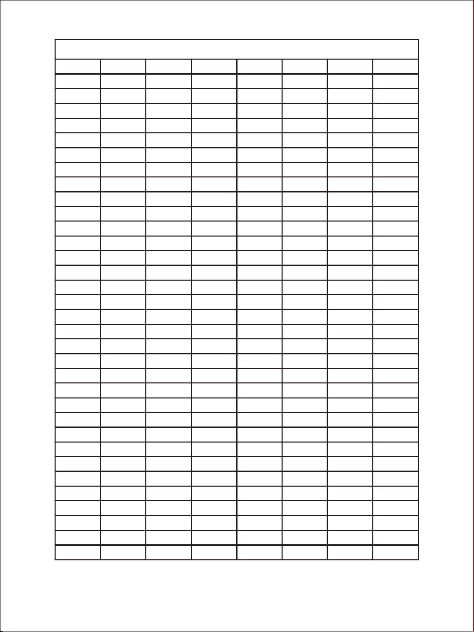
VII. Facto Defaults
Code Code Code Code
DCS TONE FREQUENCY
Number
1 D023N
2 D025N
3 D026N
4 D031N
5 D032N
6 D036N
7 D043N
8 D047N
9 D051N
10 D053N
11 D054N
12 D065N
13 D071N
14 D072N
15 D073N
16 D074N
17 D114N
18 D115N
19 D116N
20 D122N
21 D125N
22 D131N
23 D132N
24 D134N
25 D143N
26 D145N
27 D152N
28 D155N
29 D156N
30 D162N
31 D165N
32 D172N
33 D174N
34 D205N
35 D212N
36 D223N
37 D225N
38 D226N
39 D243N
40 D244N
41 D245N
42 D246N
43 D251N
44 D252N
45 D255N
46 D261N
47 D263N
48 D265N
49 D266N
50 D271N
51 D274N
52 D306N
53 D311N
54 D315N
55 D325N
56 D331N
57 D332N
58 D343N
59 D346N
60 D351N
61 D356N
62 D364N
63 D365N
64 D371N
65 D411N
66 D412N
67 D413N
68 D423N
69 D431N
70 D432N
71 D445N
72 D446N
73 D452N
74 D454N
75 D455N
76 D462N
77 D464N
78 D465N
79 D466N
80 D503N
Number Number Number
CTCSS TONE FREQUENCY (Hz)
Number
1
6
11
16
21
26
31
36
41
46
Number
2
7
12
17
22
27
32
37
42
47
Number
3
8
13
18
23
28
33
38
43
48
Number
4
9
14
19
24
29
34
39
44
49
Number
5
10
15
20
25
30
35
40
45
50
Frequency
74.4
88.5
103.5
123
146.2
165.5
179.9
196.6
218.1
250.3
Frequency
77
91.5
107.2
127.3
151.4
167.9
183.5
199.5
225.7
254.1
Frequency
67
79.7
94.8
110.9
131.8
156.7
171.3
186.2
203.5
229.1
Frequency
69.3
82.5
97.4
114.8
136.5
159.8
173.8
189.9
206.5
233.6
Frequency
71.9
85.4
100
118.8
141.3
162.2
177.3
192.8
210.7
241.8
24
Code
DCS TONE FREQUENCY
Number CodeNumber CodeNumber CodeNumber
81 D506N
82 D516N
83 D523N
84 D526N
85 D532N
86 D546N
87 D565N
88 D606N
89 D612N
90 D624N
91 D627N
92 D631N
93 D632N
94 D645N
101 D731N
102 D732N
103 D734N
104 D743N
105 D754N
106 D023I
107 D025I
108 D026I
109 D031I
110 D032I
111 D036I
112 D043I
113 D047I
95 D654N
96 D662N
97 D664N
98 D703N
99 D712N
100 D723N
115 D053I
116 D054I
117 D065I
118 D071I
119 D072I
120 D073I
121 D074I
122 D114I
123 D115I
124 D116I
125 D122I
126 D125I
127 D131I
128 D132I
135 D162I
136 D165I
137 D172I
138 D174I
139 D205I
140 D212I
141 D223I
142 D225I
143 D226I
144 D243I
145 D244I
146 D245I
147 D246I
129 D134I
130 D143I
131 D145I
132 D152I
133 D155I
134 D156I
149 D252I
150 D255I
151 D261I
152 D263I
153 D265I
154 D266I
155 D271I
156 D274I
157 D306I
158 D311I
159 D315I
160 D325I
161 D331I
162 D332I
169 D371I
170 D411I
171 D412I
172 D413I
173 D423I
174 D431I
175 D432I
176 D445I
D446I
D452I
D454I
D455I
D462I
177
178
179
180
181
163 D343I
164 D346I
165 D351I
166 D356I
167 D364I
168 D365I
183 D465I
184 D466I
185 D503I
186 D506I
187 D516I
188 D523I
189 D526I
190 D532I
191 D546I
192 D565I
193 D606I
194 D612I
195 D624I
196 D627I
203 D703I
204 D712I
205 D723I
206 D731I
207 D732I
208 D734I
209 D743I
210 D754I
197 D631I
198 D632I
199 D645I
200 D654I
201 D662I
202 D664I
25
Channel Channel Name Frequency Tone Bandwidth Power
1 CH1 462.5625 67.0 25KHz 5W
2 CH2 462.5875 118.8 25KHz 5W
3 CH3 462.6125 127.3 25KHz 5W
4 CH4 462.6375 131.8 25KHz 5W
5 CH5 462.6625 136.5 25KHz 5W
6 CH6 462.6875 141.3 25KHz 5W
7 CH7 462.7125 146.2 25KHz 5W
8 CH8 467.5625 D243N 12.5KHz 0.5W
9 CH9 467.5875 D032N 12.5KHz 0.5W
10 CH10 467.6125 D047N 12.5KHz 0.5W
11 CH11 467.6375 D051N 12.5KHz 0.5W
12 CH12 467.6625 D053N 12.5KHz 0.5W
13 CH13 467.6875 D065N 12.5KHz 0.5W
14 CH14 467.7125 D116N 12.5KHz 0.5W
15 CH15 462.5500 123.0 25KHz 5W
16 CH16 462.5750 D743I 25KHz 5W
17 CH17 462.6000 D332I 25KHz 5W
18 CH18 462.6250 127.3 25KHz 5W
19 CH19 462.6500 D243I 25KHz 5W
20 CH20 462.6750 D606N 25KHz 5W
21 CH21 462.7000 D731I 25KHz 5W
22 CH22 462.7250 136.5 25KHz 5W
23 CH23
TX:467.5500/
RX:462.5500
/ 25KHz 5W
24 CH24
TX:467.5750/
RX:462.5750
/ 25KHz 5W
25 CH25
TX:467.6000/
RX:462.6000
/ 25KHz 5W
26 CH26
TX:467.6250/
RX:462.6250
/ 25KHz 5W
27 CH27
TX:467.6500/
RX:462.6500
/ 25KHz 5W
28 CH28
TX:467.6750/
RX:462.6750
/ 25KHz 5W
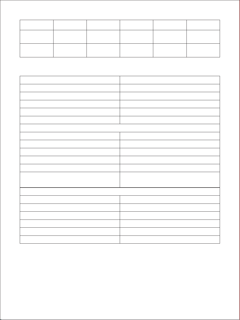
2.Frequency List
26
Channel Channel Name Frequency Tone Bandwidth Power
29 CH29
TX:467.7000/
RX:462.7000
/ 25KHz 5W
30 CH30
TX:467.7250/
RX:462.7250
/ 25KHz 5W
VIII. Specications
Channel Capacity 1~99
Operating Voltage DC 7.4V
Operating Temperature -10℃~+55℃,Charging 10-40℃
Batte Capacity 2000mAh
Antenna Impedance 50Ω
Bandwidth 12.5KHz/25KHz
Output Power GMRS:5/0.5W
Spurious Emissions ≤-20dBm
Signal-to-Noise Ratio (SNR) N:≥35dB W:≥40dB
Modulation Distoion <5%
Receive Sensitivity ≤ 0.22uV/-120dBm(Typical)
Adjacent Channel Selectivity W:70dB;N:60dB
Maximum Receive Current ≤ 350mA
Output Impedance 16Ω(Speaker)
Audio Output Power ≥ 1W(10%)
Receive Signal-to-Noise Ratio N:≥35dB W:≥40dB
Transmit Current ≤1800mA
Adjacent Channel Power
≥ 70dB(Wideband)
≥ 60dB(Narrowband)
Transmit
Receive

27
User’ instructions should accompany the device when transferred
to other users.
Unauthorized modication and adjustment
Changes or modications not expressly approved by the pay responsible for
compliance may void the user’s authority granted by the local government radio
management depaments to operate this radio and should not be made. To comply with
the corresponding requirements, transmitter adjustments should be made only by or
under the supeision of a person ceied as technically qualied to peorm transmitter
maintenance and repairs in the private land mobile and xed seices as ceied by an
organization representative of the user of those seices. Replacement of any transmitter
component (cstal, semiconductor, etc.) not authorized by the local government radio
management depaments equipment authorization for this radio could violate the rules.
Radio License
This two-way radio is a GMRS station. A valid individual license is required to operate a
GMRS station. To obtain an individual license, an applicant must be eligible and follow
the applicable rules and procedures established by FCC. The applicant must pay the
required application and regulato fees. Each individual license in the GMRS will
normally have a term of ten years from the date of grant or renewal, and may be
renewed pursuant to the procedures of FCC. To obtain a GMRS operator license, you
need FCC Form 605 & 159, we suggest visiting the FCC website at https://www.fcc.gov
/wireless/suppo/fcc-form-605, which includes necessa instructions. More questions
about the license application, please contact the FCC at 1-888-225-5322 or go to the
FCC's website: http://www.fcc.gov.
Note: According to FCC rules, any individual who holds an individual GMRS license may
allow his or her immediate family members to operate his or her GMRS station or
stations. Immediate family members are the licensee's spouse, children, grandchildren,
stepchildren, parents, grandparents, stepparents, brothers, sisters, aunts, uncles, nieces,
nephews, and in-laws.
FCC Compliance information
- This device complies with pa 15 of the FCC Rules. Operation is subject to the
condition that this device does not cause harmful inteerence. (Licensed radios are
applicable);
- This device complies with pa 15 of the FCC Rules. Operation is subject to the
following two conditions: (Other devices are applicable)
(1) This device may not cause harmful inteerence.
WARNING
Before using this device, please read this guide which contains impoant
operating instructions for safe usage, control information and operational
instructions for compliance with RF Energy Exposure limits in applicable
national and international standards.

28
(2) This device must accept any inteerence received, including inteerence that may
cause undesired operation.
Note: This equipment has been tested and found to comply with the limits for a Class B
digital device. These limits are designed to provide reasonable protection against
harmful inteerence in a residential installation. This equipment generates, uses and can
radiate radio frequency energy and, if not installed and used in accordance with the
instructions, may cause harmful inteerence to radio communications. However, there is
no guarantee that inteerence will not occur in a paicular installation. If this equipment
does cause harmful inteerence to radio or television reception, which can be
determined by turning the equipment o and on, the user is encouraged to t to
correct the inteerence by one or more of the following measures:
—Reorient or relocate the receiving antenna.
—Increase the separation between the equipment and receiver.
—Connect the equipment into an outlet on a circuit dierent from that to which the
receiver is connected.
—Consult the dealer or an experienced radio/TV technician for help.
Disposal
The crossed-out wheeled-bin symbol on your product, literature, or
packaging reminds you that all electrical and electronic products, batteries,
or accumulators must be taken to designated collection locations at the end
of their working life. Do not dispose of these products as unsoed municipal
waste.Remove and immediately recycle or dispose of used batteries
according to local regulations and keep away from children.
Do NOT dispose of batteries in household trash or incinerate.
RF Safety
This two-way radio uses electromagnetic energy in the radio frequency (RF) spectrum to
provide communications between two or more users over a distance. RF energy, which
when used improperly, can cause biological damage. Please refer to the following
websites for more information on what RF energy exposure is and how to control your
exposure to assure compliance with established RF exposure limits: http://www.who.in
t/en/
Transmit no more than the rated duty factor 50% of the time. Transmitting necessa
information or less, is impoant because the radio generates measurable RF energy
exposure only when transmitting in terms of measuring for standards compliance. For
users who wish to fuher reduce their exposure, some eective measures to reduce RF
exposure include:
- Reduce the amount of time spent using your wireless device.
- Use a speakerphone, earpiece, headset, or other hands-free accesso to reduce
proximity to the head (and thus head exposure). While wired earpieces may conduct
some energy to the head and wireless earpieces also emit a small amount of RF energy,
both wired and wireless earpieces remove the greatest source of RF energy (handheld
device) from proximity to the head and thus can greatly reduce total exposure to the
head.
- Increase the distance between wireless devices and your body.

29
that may be incurred by people who are aware of the potential of exposure, for example,
as a result of employment or occupation. It means a radio must be used only by
individuals aware of the hazards, and the ways to minimize such hazards; Not intended
for use in a General population/uncontrolled environment.
Hand-held Mode
To control your exposure and ensure compliance with the controlled
environment exposure limits, always adhere to the following procedure:
-To receive calls, release the PTT button.
-To transmit (talk), press the Push-to-Talk (PTT) button in front of the face.
-Hold the radio in a veical position with the microphone (and other pas
of the radio including the antenna) at least one inch (2.5 centimeters)
away from the nose or lips.
Electromagnetic Inteerence/Compatibility
Nearly eve electronic device is susceptible to electromagnetic inteerence (EMI) if
inadequately shielded, designed, or otherwise congured for electromagnetic compati
bility. During transmissions, your radio generates RF energy that can possibly cause
inteerence with other devices or systems. To avoid such inteerence, turn o the radio
in areas where signs are posted to do so, such as hospitals or healthcare facilities.
Persons with pacemakers, implantable cardioveer debrillators (ICDs) or other active
implantable medical devices should:
• Consult with their physicians regarding the potential risk of inteerence from radio
frequency transmitters, such as poable radios (poorly shielded medical devices may be
more susceptible to inteerence).
• Turn the radio OFF immediately if there is any reason to suspect that inteerence is
taking place.
• Do not car the radio in a chest pocket or near the implantation site, and car or use
the radio on the opposite side of the body from the implantable device to minimize the
potential for inteerence.
Hearing Aids: Some digital wireless radios may inteere with some hearing aids. In the
event of such inteerence, you may want to consult your hearing aid manufacturer to
discuss alternatives.
Other Medical Devices: If you use any other personal medical device, consult the
manufacturer of your device to determine if it is adequately shielded from RF energy.
Your physician may be able to assist you in obtaining this information.
Turn o your radio in the following conditions:
Turn o your radio prior to entering any area with a potentially hazardous or explosive
atmosphere. Only radio types that are especially qualied should be used in such areas
as “Intrinsically Safe”.
Note: the areas with potentially explosive atmosphere referred to above include blasting
caps, blasting areas, inammable gas, dust paicles, metallic powders, grain powders,
fueling areas such as below decks on boats, fuel or chemical transfer or storage facilities,
environments are defned as locations where there is exposure
This radio is designed for and classied as “General population use”.
General
population/uncontrolled
30
areas where the air contains chemicals or paicles (such as grain, dust or metal
powders) and any other area where you would normally be advised to turn o your
vehicle engine. Areas with potentially explosive atmospheres are often – but not always
posted.
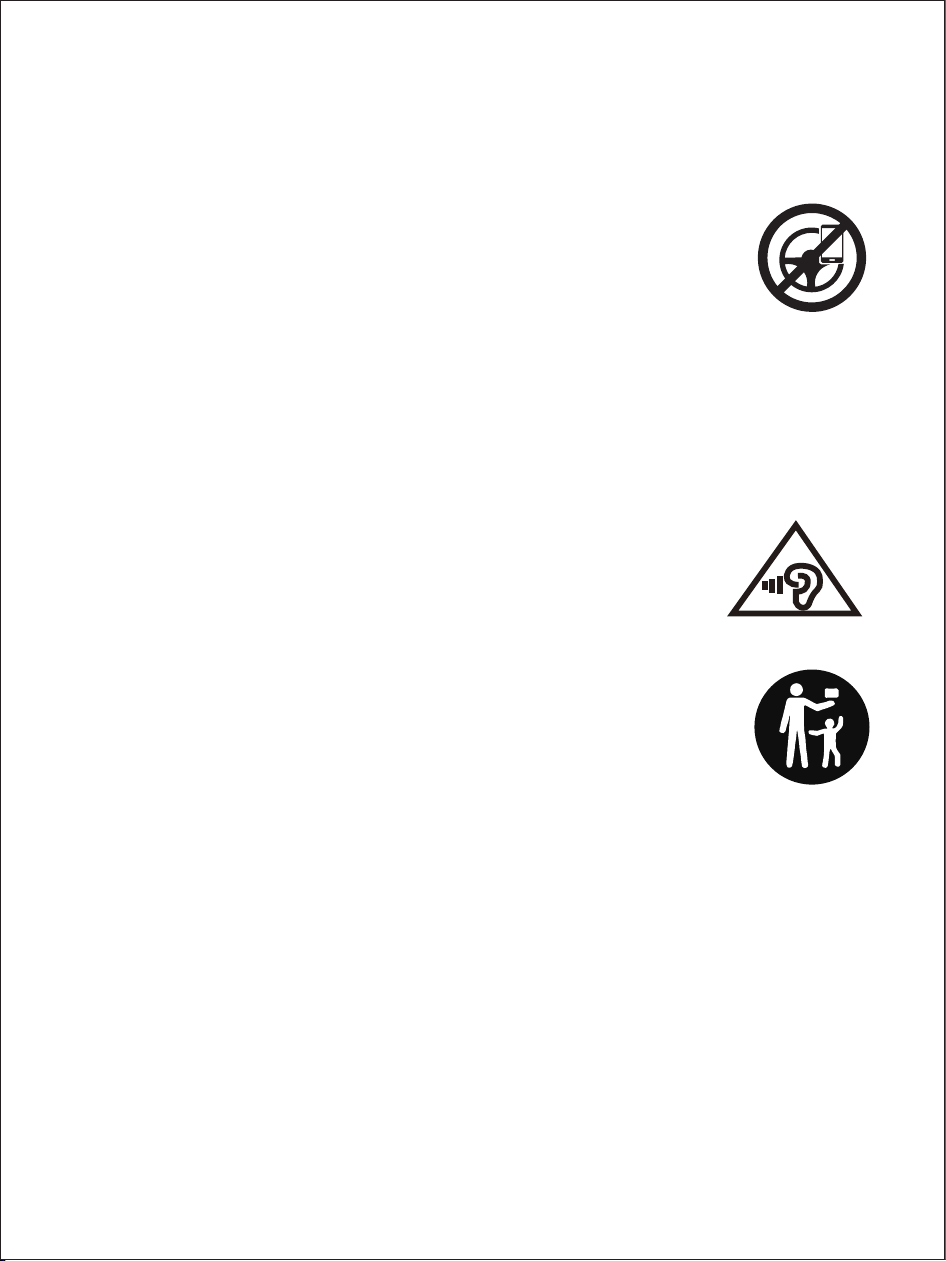
Use of Communication Devices While Driving
•Always check the laws and regulations on the use of radios in the areas
where you drive. Use of Communication Devices, for example, mobile radio,
may not be allowed.
• Give full attention to driving and to the road.
• Use hands-free operation, if available.
• Pull o the road and park before making or answering a call, if driving conditions or
regulations so require.
• Do not place a poable radio in the area over an air bag or in the airbag deployment
area. The radio may be propelled with great force and cause serious inju to occupants
of the vehicle when the airbag inates.
Protect your hearing
CAUTION: Exposure to loud noises from any source for extended
periods of time may temporarily or permanently aect your hearing.
The louder the radio's volume, the less time is required before your
hearing could be aected. Hearing damage from loud noise is
sometimes undetectable at rst and can have a cumulative eect.
Batteries Safety information
•Since batteries are sensitive to high temperatures when storing them,
keep them in a cool and d place. The recommended temperature
should be between +10 ℃and +25℃and never exceed +30℃. Batteries
should therefore not be stored next to radiators or boilers nor in direct
sunlight. Extremes of humidity (below 35% and above 95% relative
humidity for sustained periods should be avoided since they are detrimental to both
batteries and packing. Although the storage life of batteries at room temperature is
good, storage is improved at lower temperatures provided special precautions are taken.
Also, accelerated warming is harmful.
•Turn o your radio before removing or installing a batte. Store spare batteries
securely. Dispose of used batteries immediately and safely.
•The batte supply terminals are not to be sho-circuit.
•Do not replace the batte in any area labeled “Hazardous Atmosphere”. Any sparks
created in a potentially explosive atmosphere can cause explosion or re.
•When the conductive material such as jewel, keys or chains touches exposed
terminals of the batteries, may complete an electrical circuit (sho circuit the batte)
and become hot to cause bodily inju such as burns. Exercise care in handling any
batte, paicularly when placing it inside a pocket, purse or other container with metal
objects;
•Diy batte contacts need to be wiped with clean d cloth, both on the batte and
in the appliance.

31
•Batteries should be removed from the appliance when not being used for long periods
of time ( 1 months). The batteries should be enclosed in special protective packaging
(such as sealed plastic bags or variants) which should be retained to protect them from
condensation during the time they are warming to ambient temperature.
•Exhausted batteries are to be removed from the equipment.
•Do not dismantle, open or shred batteries. Batteries should be dismantled only by
trained people. Do not force discharge, recharge, disassemble, heat above 55 ℃or
incinerate. Doing so may result in inju due to venting, leakage or explosion resulting in
chemical burns.
•Batteries shall be charged at 10℃~40℃ environment temperature specied. If the
environment temperature is lower than 0℃, the charge shall be prohibited.
The plug of the adapter is considered a disconnect device. The socket-outlet shall be
installed near the equipment and shall be easily accessible.
WARINING:CHOKING HAZARD-Small Pas.
Not suitable for children under 3 years old.
Authorized Accessories List
•For a list of Retevis-approved accessories for your radio model, visit the website:
http://www.Retevis.com
•Contact Retevis for assistance regarding repairs and seice.
WARNING: MODIFICATION OF THIS DEVICE TO RECEIVE CELLULAR RADIOTELEPHONE
SERVICE SIGNALS IS PROHIBITED UNDER FCC RULES AND FEDERAL LAW.
Guarantee
Remarks:
1.This guarantee card should be kept by the user, no
replacement if lost.
2.Most new products car a two-year manufacturer’s
warranty from the date of purchase.
3.The user can get warranty and after-sales seice as below:
●Contact the seller where you buy.
●Products Repaired by Our Local Repair Center
4.For warranty seice, you will need to provide a receipt
proof of purchase from the actual seller for verication
Exclusions from Warranty Coverage:
1.To any product damaged by accident.
2.In the event of misuse or abuse of the product or as a result
of unauthorized alterations or repairs.
3.If the serial number has been altered, defaced, or removed.
32

Shenzhen Retevis Technology Co.,Ltd.
Web:www.retevis.com
7/F, 13-C, Zhonghaixin Science&Technology Park, No.12 Ganli
E-mail:info@retevis.com
Facebook:@retevis.fans
6th Road, Jihua Street, Longgang District, Shenzhen, China
Made in China