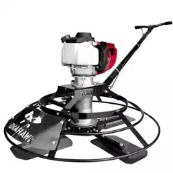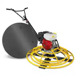
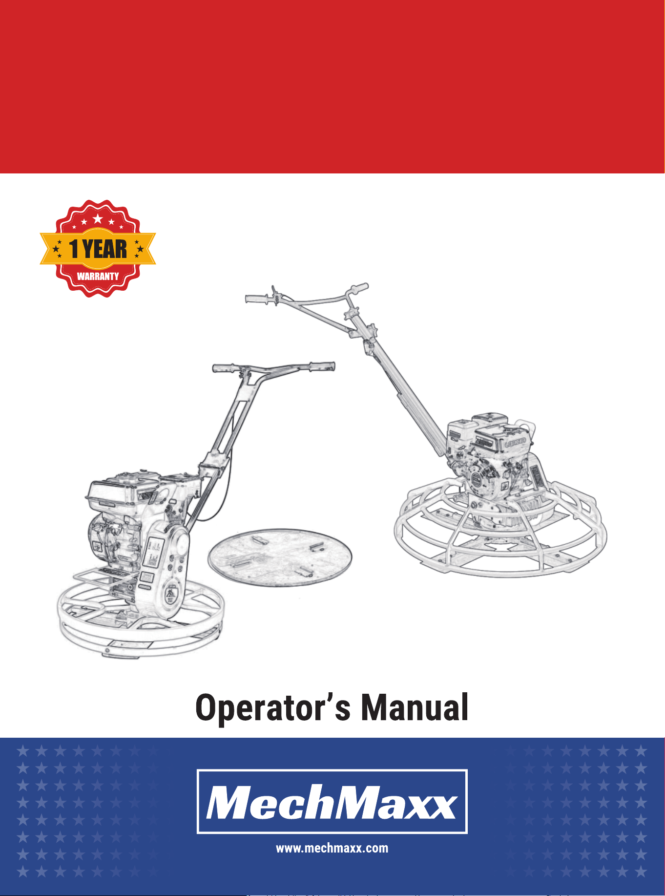
PT22H/PT22Z
PT36H/PT36Z
PT46H/PT46Z
Model:
WALK BEHIND TROWEL


TABLE OF CONTENTS
TABLE OF CONTENTS 1 WORK BACK-CHECK TABLE
TROUBLE SHOOTING
PARTS DIAGRAM (PT22H/PT22Z GENERAL ASSEMBLY)
PARTS LIST (PT22H/PT22Z GENERAL ASSEMBLY)
PARTS DIAGRAM (PT36H/PT36Z/PT46H/PT46Z GENERAL ASSEMBLY)
PARTS LIST (PT36H/PT36Z/PT46H/PT46Z GENERAL ASSEMBLY)
EXHAUST NOTICE
8
GASOLINE IS FLAMMABLE
8
DEFEND HIGH TEMPERATURE
8
LABEL LOCATIONS
4
SAFETY LABELS
4
OPERATING LABELS
6
OPERATOR
8
RUNNING NOTICE
8
TRANSPORT NOTICE
8
4
SAFETY LABELS
2
SPECIFICATIONS
SPECIAL WARNING
7
SKETCH MAP 7
8
SAFETY NOTICE
CHECK THE ENGINE OIL
9
CHECK FUEL
9
ENGINE SECTION
11
PEDESTAL SECTION
11
CHECK THE GEAR OIL
9
TURN OFF
10
9
CHECK BEFORE USING
10
TURN ON
11
SIMPLE MAINTENANCE
12
13
16
17
19
20
1
www.mechmaxx.com
TABLE OF CONTENTS
SPECIFICATIONS
2
www.mechmaxx.com
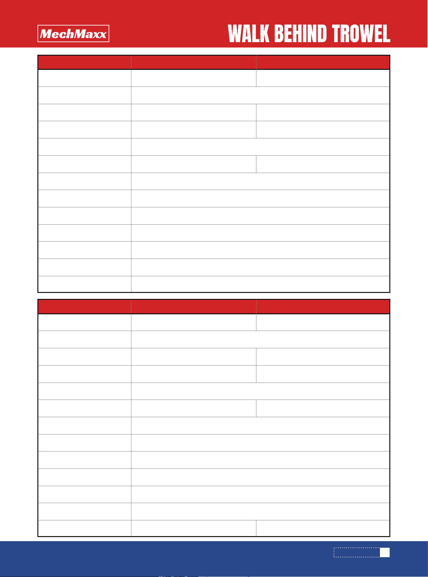
Model PT22H PT22Z
Engine
Engine Type
Engine Displacement
Horsepower
Start System
Fuel Tank Capacity
Engine Oil Capacity
Troweling Diameter
Rotor Speed
No. of Blades
Blade Pitch
Overall Dimension (LxWxH)
Weight
Honda GX160
Single-Cylinder, 4-Stroke, Air-Cooled, OHV Gasoline Engine
163 cc
4.8 HP (3.6kW) @ 3600 RPM
Recoil
3.3 US qt (3.1L)
0.61 US qt (0.6L)
23 in
60 - 125 RPM
4
0 - 15°
33 x 24 x 23 in
123lbs
Zonsen GB210
208 cc
5.8 HP (4.3kW) @ 3600 RPM
2.8 US qt (2.6L)
SPECIFICATIONS
3
www.mechmaxx.com
Model PT36H PT36Z
Engine
Engine Type
Engine Displacement
Horsepower
Start System
Fuel Tank Capacity
Engine Oil Capacity
Troweling Diameter
Rotor Speed
No. of Blades
Blade Pitch
Overall Dimension (LxWxH)
Weight
Honda GX160
Single-Cylinder, 4-Stroke, Air-Cooled, OHV Gasoline Engine
163 cc
4.8 HP (3.6kW) @ 3600 RPM
Recoil
3.3 US qt (3.1L)
0.61 US qt (0.6L)
36 in
60 - 125 RPM
4
0 - 15°
38 x 38 x 24 in
176lbs
Zonsen GB210
208 cc
5.8 HP (4.3kW) @ 3600 RPM
2.8 US qt (2.6L)
Model PT46H PT46Z
Engine
Engine Type
Engine Displacement
Horsepower
Start System
Fuel Tank Capacity
Engine Oil Capacity
Troweling Diameter
Rotor Speed
No. of Blades
Blade Pitch
Overall Dimension (LxWxH)
Weight
Honda GX270
Single-Cylinder, 4-Stroke, Air-Cooled, OHV Gasoline Engine
269 cc
8.5 HP (6.3kW) @ 3600 RPM
Recoil
5.6 US qt (5.3 L)
1.16 US qt (1.1 L)
44 in
60 - 125 RPM
4
0 - 15°
47 x 47 x 24 in
220lbs
Zonsen GB460B
459 cc
15.0 HP (11kW) @ 3600 RPM
6.3 US qt (6 L)
231lbs
SPECIFICATIONS
SAFETY LABELS
4
www.mechmaxx.com
ROTATING BLADE
HAZARD
Keep hands and feet
clear of rings.
Stop engine before
servicing.
Safety Start
GEAR BOX
OIL
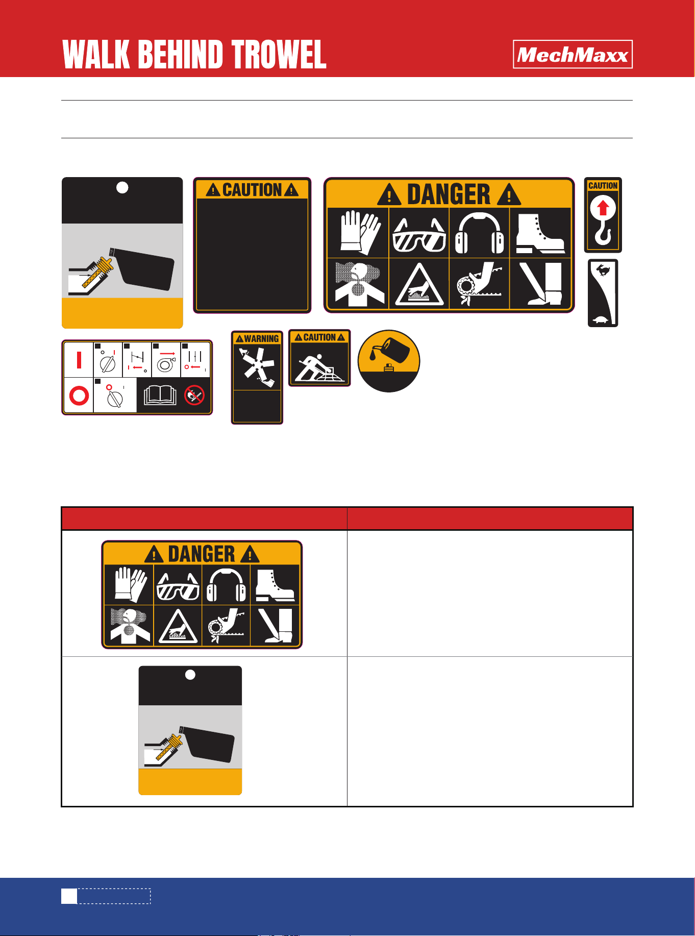
The machines use international pictorial labels where needed. These labels are described below:
NOTE:
These molded-in label contains important safety and operating information. If the label becomes illegible,
replace it immediately. Contact MechMaxx or an authorized service dealer for replacement labels.
DANGER!
Wear appropriate PPE including gloves, eye
protection, hearing protection, and safety footwear.
Do not touch the engine or muffler during or immediately
after operation—hot surfaces may cause burns.
Keep hands and feet away from moving parts.
Operate only in well-ventilated areas to avoid carbon
monoxide exposure.
WARNING!
Before use, fill the fuel tank with gasoline
and add engine oil to the proper level.
Operating the engine with low or no oil will cause
permanent engine damage and may void the warranty.
Refer to the engine manual for detailed instructions.
LABEL LOCATIONS
SAFETY LABELS
Label Meaning
BEFORE USE
• REFER TO THE ENGINE MANUAL FOR DETAILS.
• OPERATING WITH LOW OR NO ENGINE OIL
WILL CAUSE PERMANENT DAMAGE AND VOID
WARRANTY.
1. FILL GASOLINE.
2. ADD ENGINE OIL.
OIL
FULL
LOW
BEFORE USE
• REFER TO THE ENGINE MANUAL FOR DETAILS.
• OPERATING WITH LOW OR NO ENGINE OIL WILL
CAUSE PERMANENT DAMAGE AND VOID
WARRANTY.
1. FILL GASOLINE.
2. ADD ENGINE OIL.
OIL
FULL
LOW
• READ PRODUCT MANUAL BEFORE
OPERATING OR SERVICING THIS MACHINE.
• TRANSPORT THIS MACHINE IN THE UPRIGHT
POSITION. DO NOT TIP OVER THE MACHINE
AT ANY TIME. IMPROPER HANDLING MAY
CAUSE DAMAGE.
• ALWAYS KEEP UNAUTHORIZED,
INEXPERIENCED, UNTRAINED PEOPLE AWAY
FROM THIS MACHINE.
• MAKE SURE ALL SAFETY DEVICES ARE
OPERATIONAL BEFORE THIS MACHINE IS
STARTED. MAKE SURE ENGINE IS TURNED
OFF AND SPARK PLUG WIRE
DISCONNECTED BEFORE SERVISING THE
MACHINE OR COMING IN CONTACT WITH
ANY MOVING PART.
• NEVER LEAVE MACHINE UNATTENDED
WHEN OPERATING. ALWAYS STOP ENGINE
AND ALLOW ENGINE TO COOL BEFORE
ADDING FUEL OR OIL.
1
1
2 3 4
SAFETY LABELS
5
www.mechmaxx.com
ROTATING BLADE
HAZARD
Keep hands and feet
clear of rings.
Stop engine before
servicing.
Safety Start
GEAR BOX
OIL
• READ PRODUCT MANUAL BEFORE
OPERATING OR SERVICING THIS MACHINE.
• TRANSPORT THIS MACHINE IN THE
UPRIGHT POSITION. DO NOT TIP OVER THE
MACHINE AT ANY TIME. IMPROPER
HANDLING MAY CAUSE DAMAGE.
• ALWAYS KEEP UNAUTHORIZED,
INEXPERIENCED, UNTRAINED PEOPLE
AWAY FROM THIS MACHINE.
• MAKE SURE ALL SAFETY DEVICES ARE
OPERATIONAL BEFORE THIS MACHINE IS
STARTED. MAKE SURE ENGINE IS TURNED
OFF AND SPARK PLUG WIRE
DISCONNECTED BEFORE SERVISING THE
MACHINE OR COMING IN CONTACT WITH
ANY MOVING PART.
• NEVER LEAVE MACHINE UNATTENDED
WHEN OPERATING. ALWAYS STOP ENGINE
AND ALLOW ENGINE TO COOL BEFORE
ADDING FUEL OR OIL.
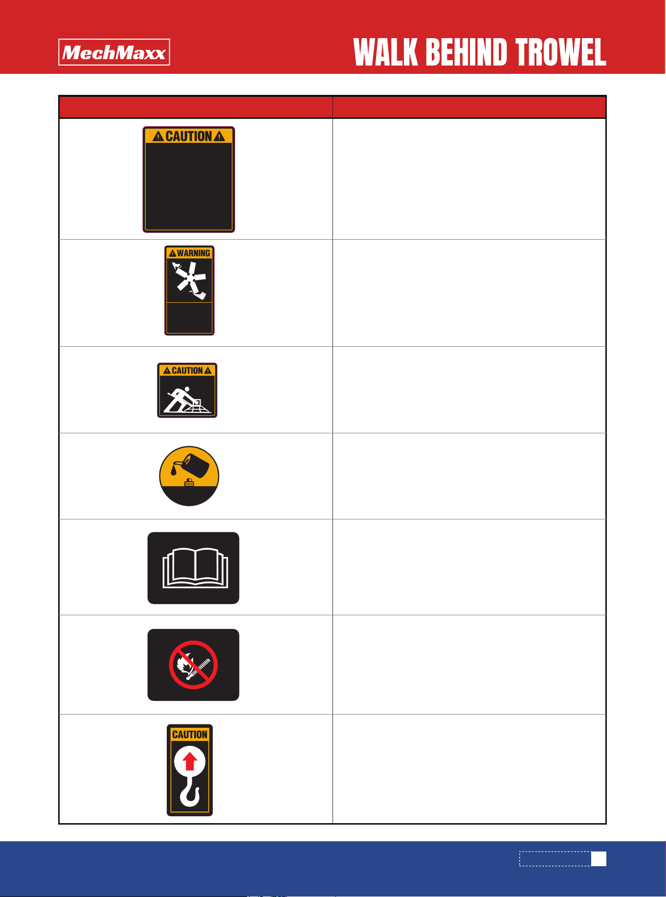
CAUTION!
Read the operator’s manual before operating
the machine. Transport only in the upright position. Keep
unauthorized persons away from the equipment. Ensure
all safety devices are in place before starting the engine.
Stop the engine and allow it to cool before servicing or
refueling. Never leave the machine running unattended.
WARNING!
Rotating blades may cause serious injury.
Keep hands and feet away from the guard ring and blade
area during operation. Stop the engine before inspection,
cleaning, or servicing.
CAUTION!
Use safe starting procedures. Maintain
stable footing and proper control of the machine when
starting the engine.
NOTICE:
Gearbox oil. Check and maintain the gearbox
oil at the specified level using the recommended oil.
CAUTION!
Read the operator's manual for machine
information.
DANGER!
Keep sparks, flames, and hot materials away
from the machine.
CAUTION!
Lifting point.
Label Meaning
SAFETY LABELS
6
www.mechmaxx.com
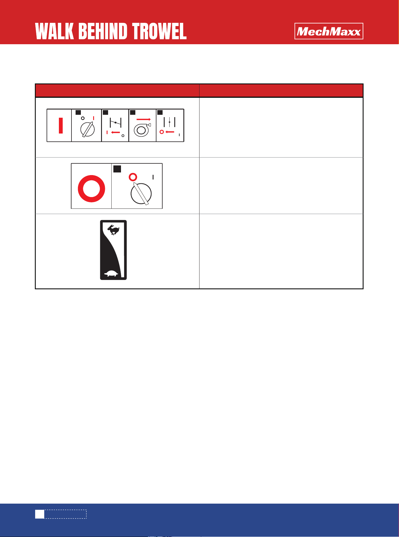
The machines use international pictorial labels where needed. These labels are described below:
OPERATING LABELS
1
1 2 3 4
START THE ENGINE
1. Turn the engine switch to the ON position
2. Close the choke
3. Pull the recoil starter
4. Open the choke.
Stop the engine:
Turn the engine switch to OFF position.
Throttle control lever:
Turtle = ldle or Slow
Rabbit = Full or Fast
Label Meaning
SAFETY LABELS
Please be sure to check the level of oil, as following:
1.The level of oil in engine, please be sure the level of oil is the r ange within the oil ruler scale. The engine would be
shattered if the oil level is too low or without oil.
2.The level of oil in pedestal, Please be sure the level of oil is below edge of the oil entrance. The speed-down machine
would be s hattered if the oil level is too low or without oil. Please close the fuel switch before stopping the engine if the
engine Will not be use for m ore one week, make the surplus oil be use out in the wasting on container, because the oil is
the volatilH liquid. It would remain the semisolid matter after volatil the wasting oil container m ight be jammed, and the
engine can't work normally.
Please be sure to read and know well the instr uction and the details of the engine ins truction and the operating regular.
The maintenance and exact use is necessary in order to ensure person safety, extend useful life and reduce the troubles.
(You may match the machine indication to read the manual, It is concise and understandable.)
SPECIAL WARNING
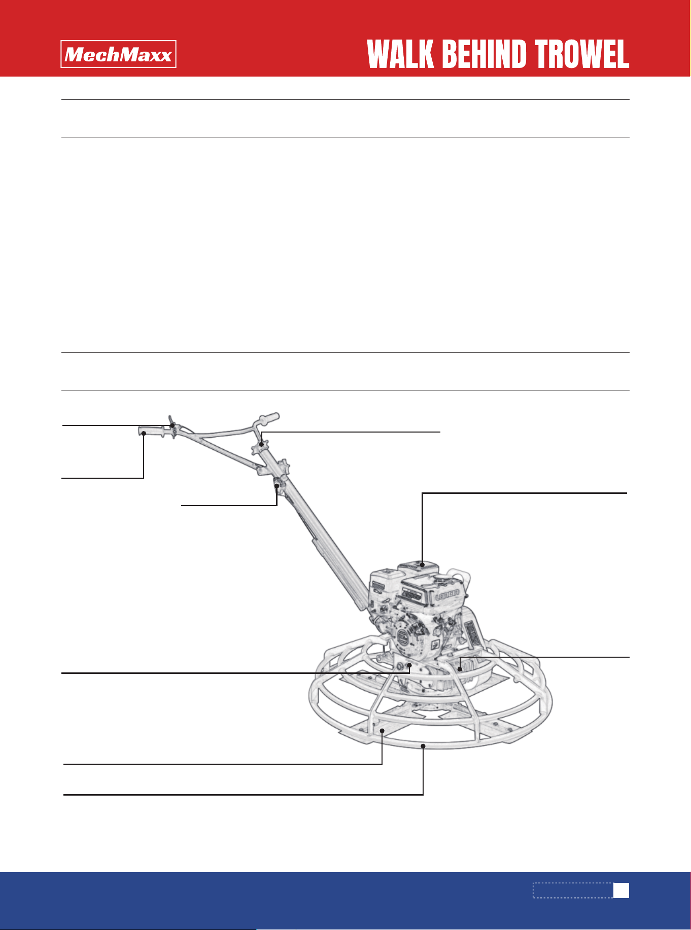
MACHINE OVERVIEW
High & low turn wheel
Engine
Gearbox
Blade
Guard Ring
Gear Oil Fill Port
Pitch Control Knob
Throttle Lever
Handle
7
www.mechmaxx.com
SPECIAL WARNING
8
www.mechmaxx.com
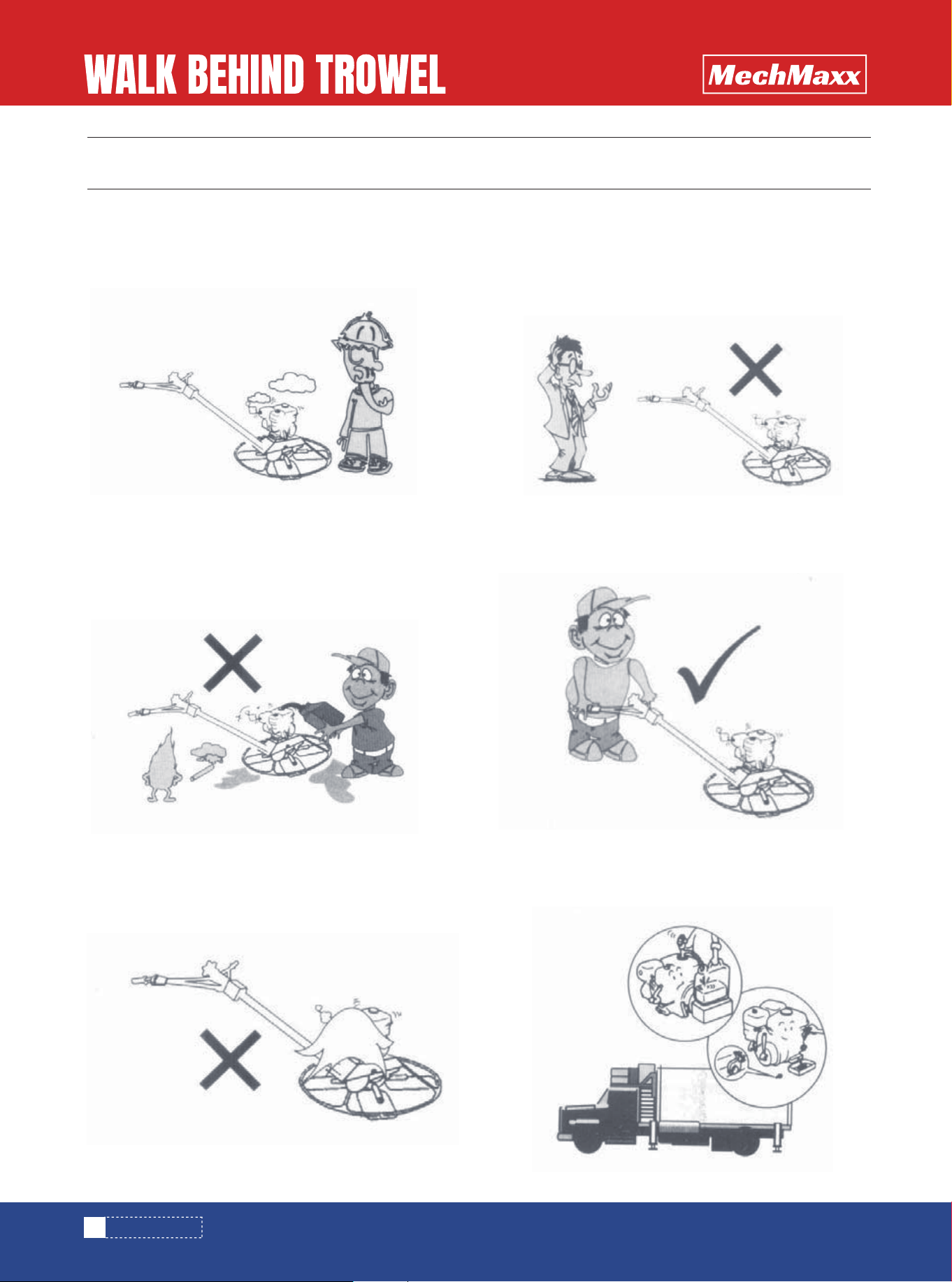
Can’t breathe in exhaust
Please rise the power trowel LQ the place with aerating
all right.
EXHAUST NOTICE
Please the person unauthorized or which is not trained
do not touch the equipment.
Please check often the sate of switch in order to keep
safety.
OPERATOR
As to operation and running components, please be sure
to keep all safe equipments running without troubles.
RUNNING NOTICE
Please empty the engine gasoline when the machines
are transported for far distance, in case the fuel machine
can't work.
TRANSPORT NOTICE
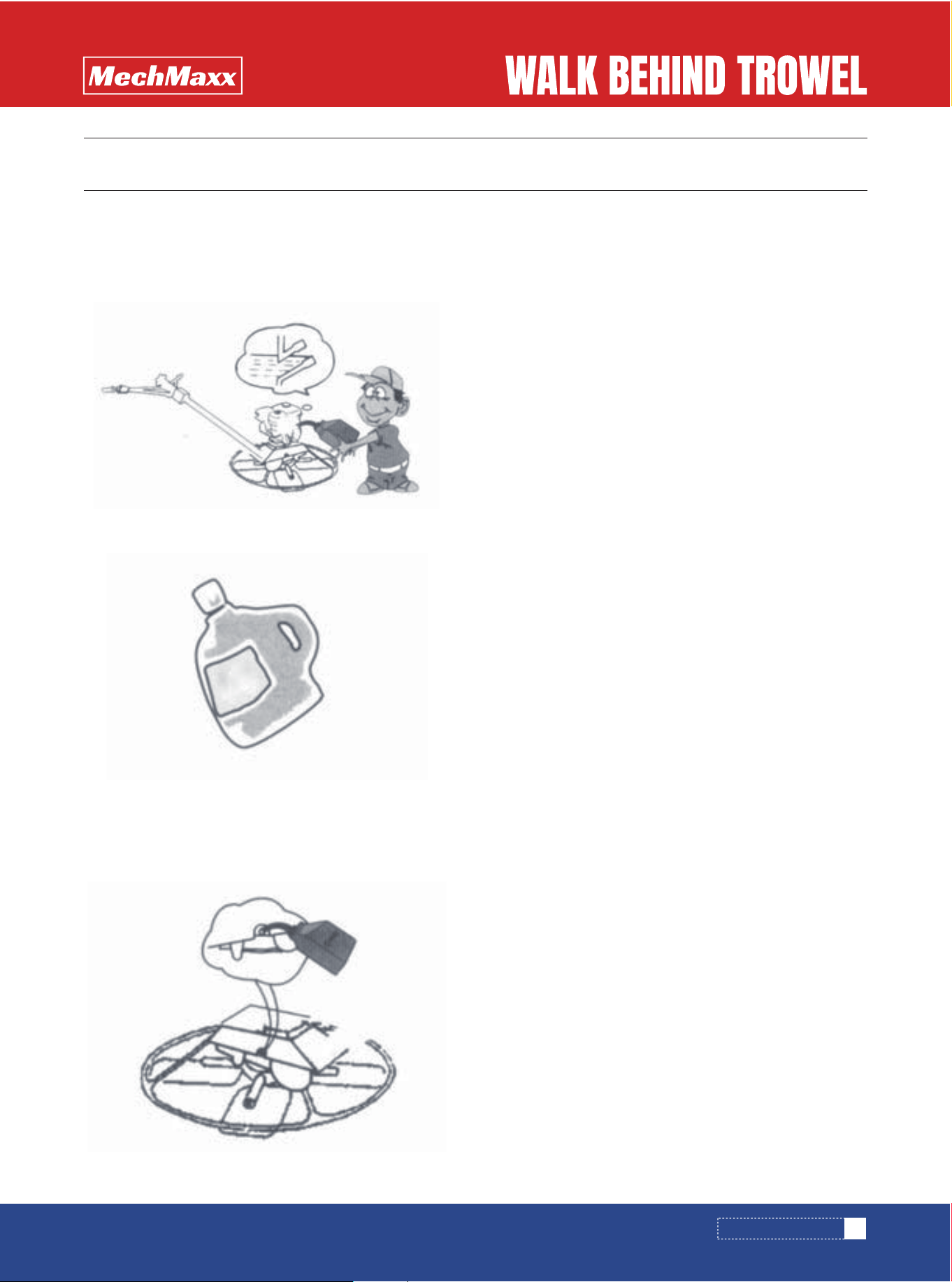
GASOLINE IS FLAMMABLE
SAFETY NOTICE
SAFETY NOTICE
Please stop the engine before putting oil gasoline.
Don’t add the gasoline too full and lean to using the
machine
No smoking while you are putting on gasoline.
DEFEND HIGH TEMPERATURE
Don’t touch muffler or cover when tK e machine is running
or stopping. Don’t cover the machine by cloth or plastic
while it is running.
9
www.mechmaxx.com
Please put on machine oil first before using.
Because the machine Oil is drawn out before the
products are leave factory.
CHECK THE ENGINE OIL
The product must use the normal lead-free gasoline.
CHECK FUEL
CHECK BEFORE USING
CHECK BEFORE USING
Because put on gear oil before using.
Because the gear oil is drawn out in the special status
(air freight) when the products are transported.
CHECK THE GEAR OIL
10
www.mechmaxx.com
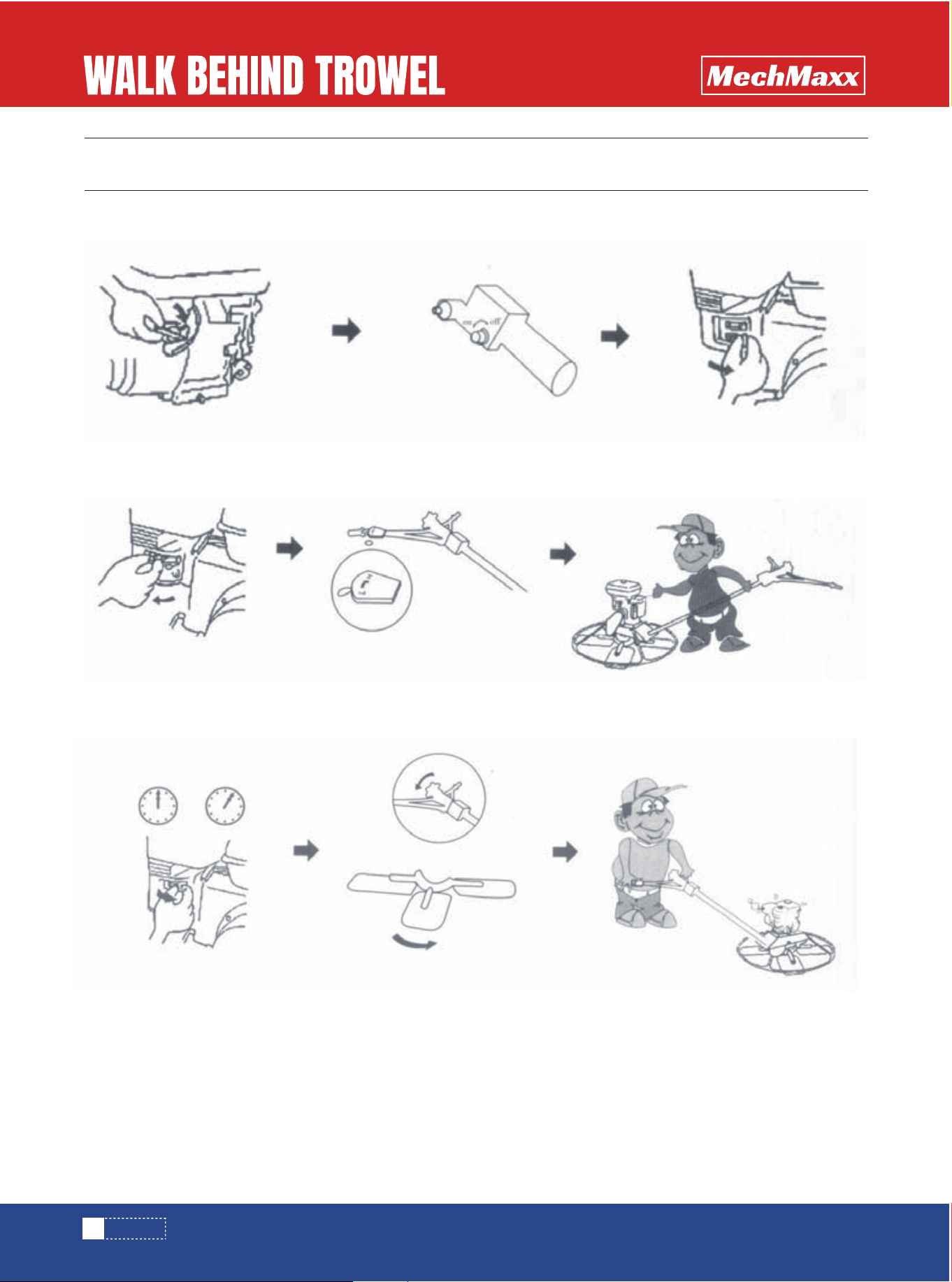
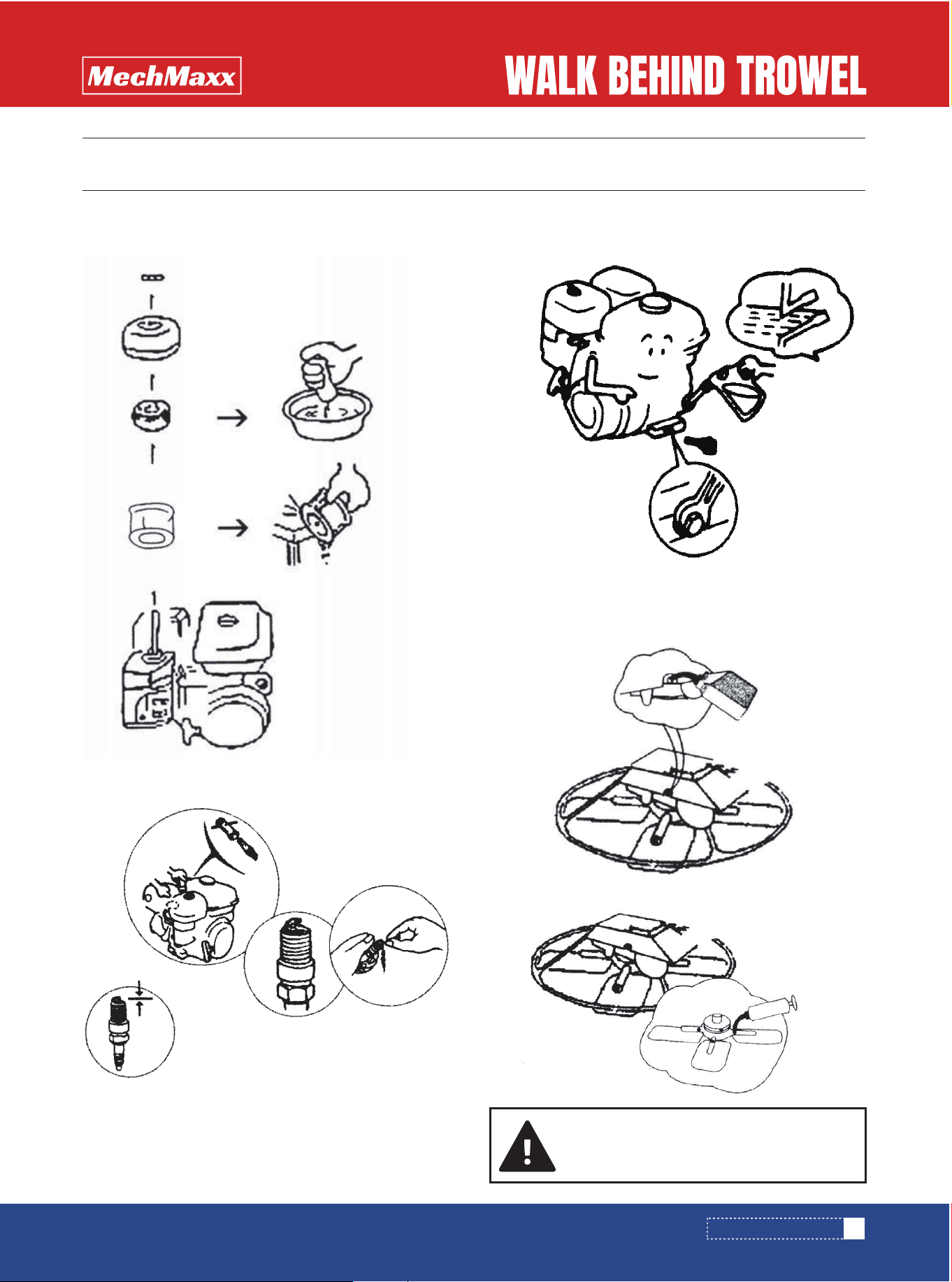
1. Set the engine switch to ON. 2. Set the safety switch to ON. 3. Open the fuel valve.
7. Allow the engine to warm up for 3 to
5 minutes, then gradually open the
choke.
1. Reduce the throttle to LOW / IDLE.
2. Set the safety switch to OFF.
3. Return the blades to the flat position.
8. Adjust the blade pitch to the
desired position.
9. Hold the handle with both hands and
adjust the throttle to the proper operat-
ing speed.
TURN OFF
TURN ON
TURN ON
4. Close the choke for a cold engine. 5. Set the throttle lever to the
middle position.
6. Hold the handle firmly and pull the
recoil starter.
11
www.mechmaxx.com
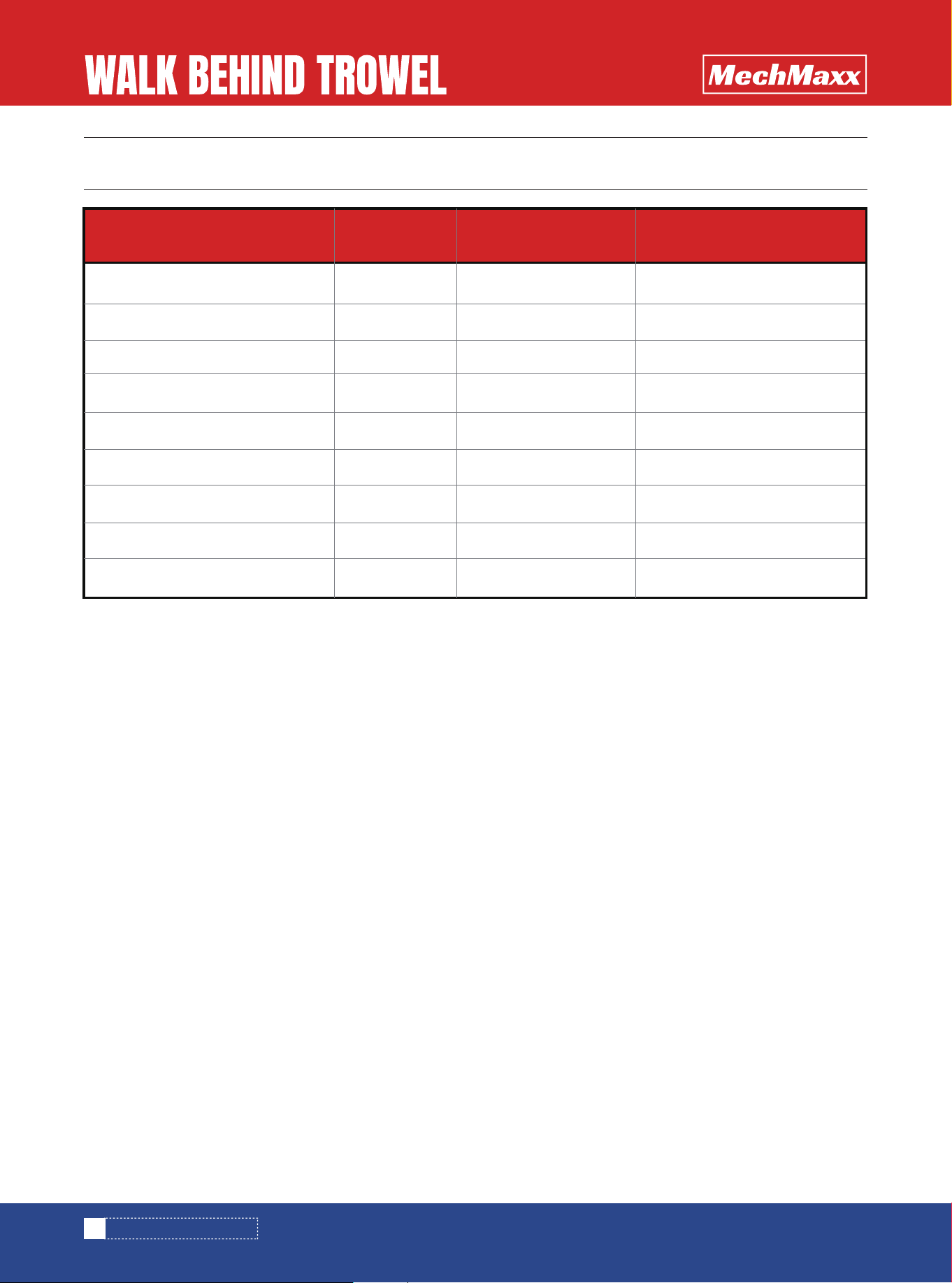
Step: 1.Check and clear the air colander
Step: 2.Check and clear the spark plug
Step: 3. Check and change the machine oil
Step: 1. Append and change the gear oil
Step: 2.Check and clear the spark plug
ENGINE SECTION
PEDESTAL SECTION
SIMPLE MAINTENANCE
SIMPLE MAINTENANCE
clear cumulate
carbon
Adjust the gap to proper range (approximately 0.02-0.03
in)
Step: 2. Butter blade and under pan in case rust
Please maintain the machine termly refer to
the work back-check table
12
www.mechmaxx.com
WORK BACK-CHECK TABLE
WORK BACK-CHECK TABLE
(Day/Times)
Every 8 hours
(Week/Times)
Every 50 hours
(Month/Times)
Every 200 hours
A. Engine
1. Machine Oil
2. Spark Plug
3. Air Colander
B. Deceleration Machine
C. Blade Rest Oil Ni
D. Axletree lid Oil Nib
E. Strap
F. Machine movement Point
Change Oil
Check
Clean out
Check gear Oil
Butter
Butter
Check
Add a little engine oil
Check and Change Gear Oil
Check or Change
Check
13
www.mechmaxx.com
TROUBLESHOOTING
TROUBLESHOOTING
Problem/Symptom Possible Cause Corrective Action
Engine will not start
Engine starts but runs poorly
Engine starts but lacks power
Engine surges or speed is unstable
Engine overheats
Engine switch is OFF
Safety switch is OFF
Fuel valve is closed
Turn the engine switch to the ON
position.
Set the safety switch to the ON
position.
Open the fuel valve.
Fuel tank is empty
Choke position is incorrect
Spark plug wire is loose or
disconnected
Spark plug is fouled or damaged
Engine oil level is too low
Fill the tank with clean, fresh
unleaded gasoline.
Close the choke for a cold engine.
Open or partially open the choke for
a warm engine.
Clean or replace the spark plug.
Add engine oil to the specified level.
Air cleaner is clogged Clean or replace the air cleaner.
Fuel is stale or contaminated
Choke is left closed after warm-up
Air cleaner is dirty
Drain the fuel system and refill with
fresh gasoline.
Gradually open the choke after the
engine starts.
Clean or replace the air cleaner.
Spark plug is fouled
Fuel is stale or contaminated
Throttle linkage is out of adjustment
Governor or throttle linkage is
sticking
Cooling fins are blocked by dirt or
debris
Clean or replace the spark plug.
Replace with fresh gasoline.
Inspect the throttle cable and
linkage. Adjust if necessary.
Inspect linkage movement and
correct any binding.
Clean the engine cooling fins and
surrounding areas.
Reconnect the spark plug wire
securely.
Before performing any inspection or maintenance, stop the engine, allow all moving parts to stop completely.
If the problem cannot be corrected using the procedures below, contact MechMaxx or a qualified service technician
14
www.mechmaxx.com
TROUBLESHOOTING
Problem/Symptom Possible Cause Corrective Action
Engine runs but blades do not rotate
properly
Engine runs but blades rotate weakly
Engine runs but blade response is
delayed
Machine pulls excessively to one side
Machine is difficult to steer
Machine is unstable during operation
Machine is difficult to control
Machine jerks or feels unbalanced
Surface finish is uneven
Machine leaves marks on the surface
Machine does not float properly
Machine does not finish smoothly
Excessive vibration or unusual noise
Throttle speed is too low
Drive belt is loose or worn
Clutch is slipping or damaged
Increase engine speed to the proper
operating range.
Inspect belt tension and condition.
Adjust or replace as needed.
Inspect the clutch. Repair or replace
if necessary.
Gearbox problem
Belt or clutch is contaminated with
oil or grease
Blade pitch is uneven
Handle position is not properly
adjusted
Blades are worn unevenly
Check gearbox oil level and inspect
the gearbox for damage.
Clean contaminated parts and
correct the source of the leak.
Adjust the handle to a comfortable
and controllable position.
Replace blades as a complete
matched set.
Operating speed is too high for
conditions
Foreign material is stuck around the
spider or blade arms
Blade pitch is incorrect
Reduce speed and recheck the blade
pitch setting.
Clean all rotating components
thoroughly.
Adjust blade pitch to suit finishing
conditions.
Blades are worn or bent
Blade angle is too aggressive
Wrong blades or pan are used
Concrete condition is not suitable
Blade arms or blades are damaged
Replace damaged or worn blades.
Reduce blade pitch.
Install the correct blades or float
pan for the application.
Operate only when slab condition is
appropriate for troweling.
Inspect and replace damaged parts.
Fasteners are loose
Gearbox or rotating assembly is worn
Tighten all fasteners to specification.
Inspect and repair as necessary.
Gearbox oil level is low Check and refill gearbox oil.
Adjust blade pitch evenly.
15
www.mechmaxx.com
TROUBLESHOOTING
Problem/Symptom Possible Cause Corrective Action
Machine feels heavy or drags during
rotation
Blade pitch will not change
Blade pitch is difficult to adjust
Blade pitch is inconsistent
Machine is difficult to start safely
Machine jumps or moves unexpectedly
at startup
Handle control feels loose
Rotating assembly is contaminated
or damaged
Cable or adjustment mechanism is
damaged
Pitch control linkage is jammed
Clean and inspect the spider, blade
arms, and gearbox output area
Inspect and replace damaged parts.
Inspect and clean the linkage.
Linkage is out of adjustment
Operator position is unstable
Throttle is set too high during
startup
Handle fasteners are loose
Adjust linkage evenly on both sides.
Stand in a stable position and
maintain firm control of the handle.
Tighten the handle hardware.
Start with the throttle in the
recommended position.
16
www.mechmaxx.com
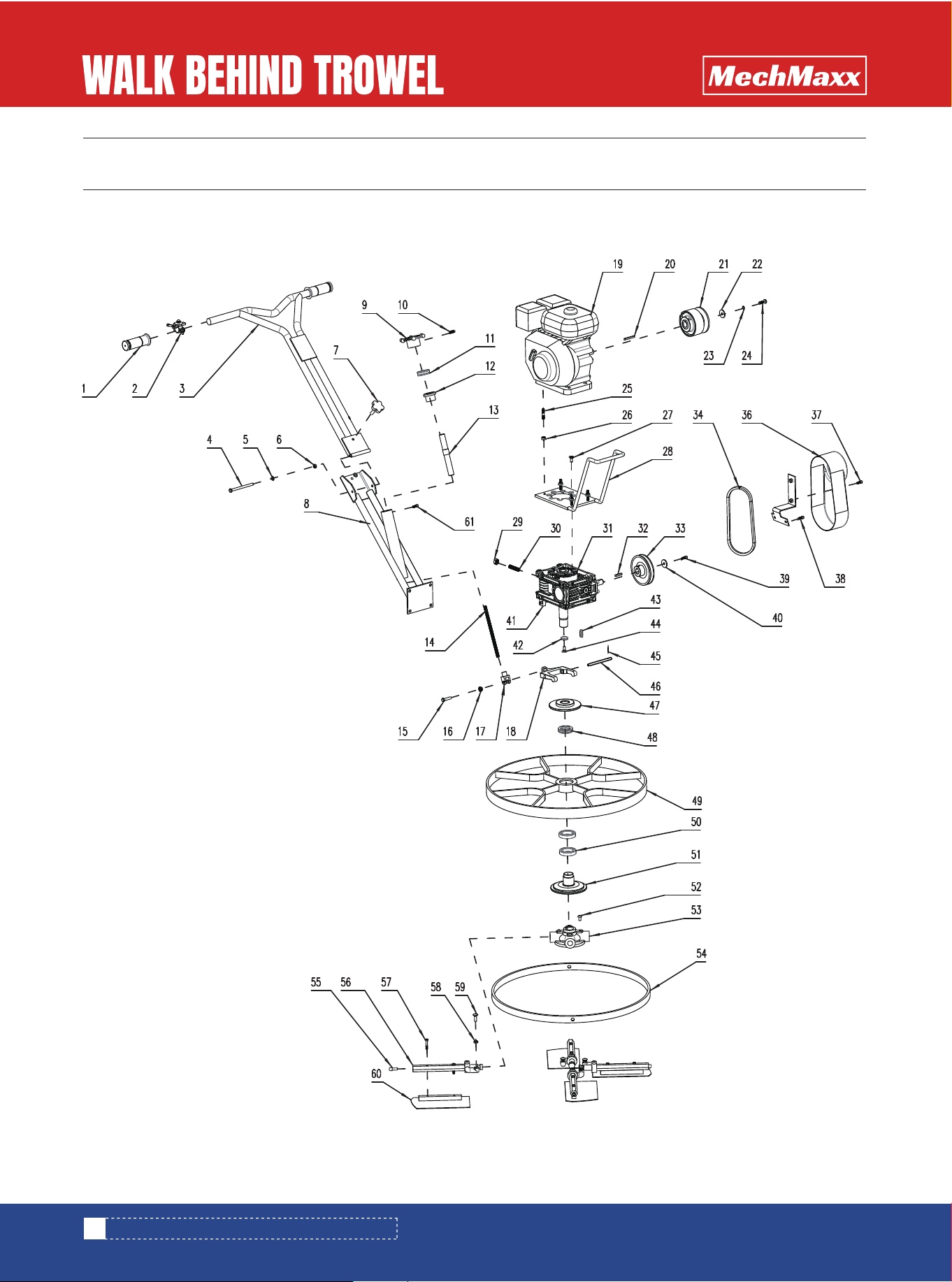
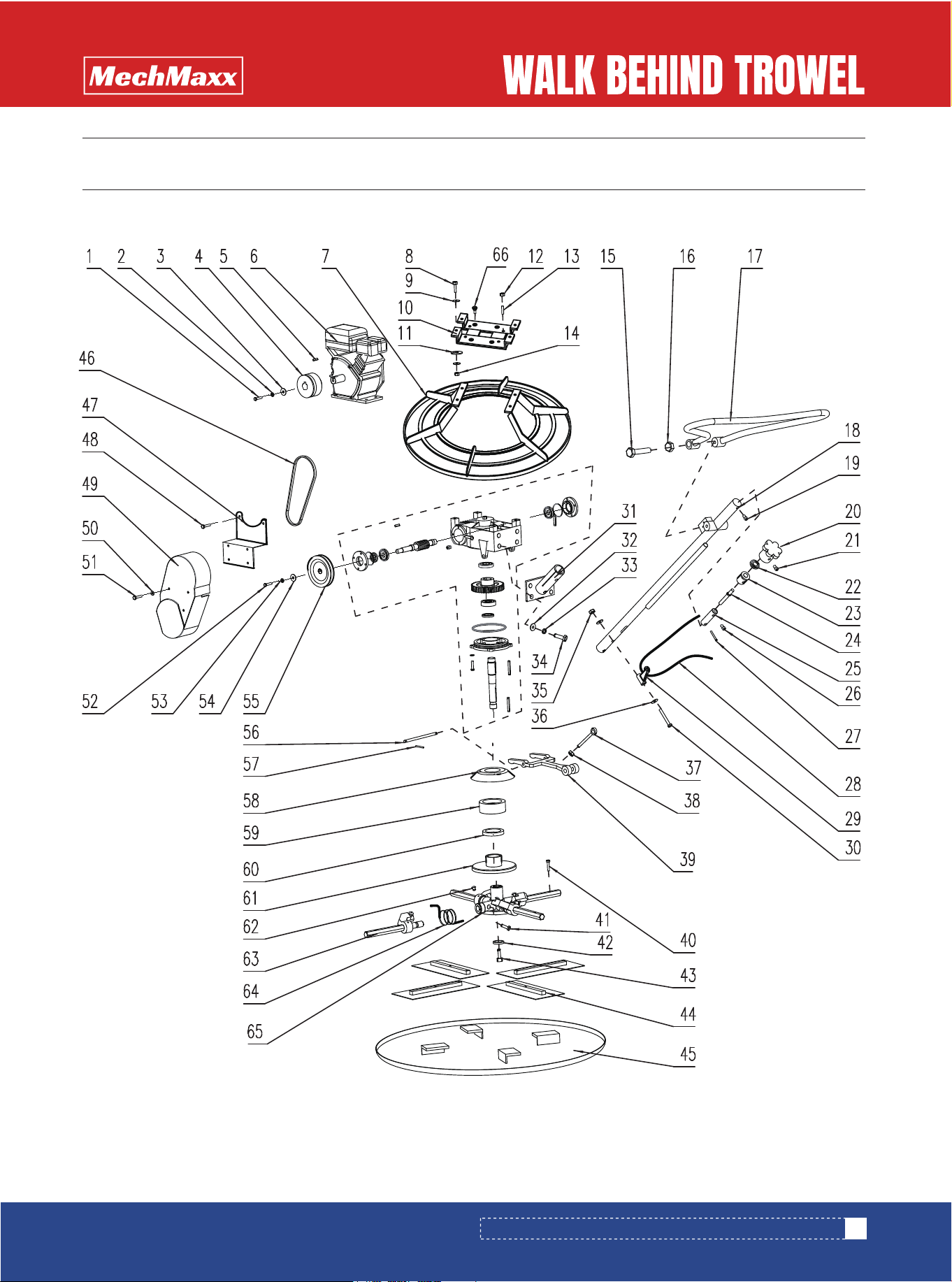
PARTS DIAGRAM (PT22H/PT22Z GENERAL ASSEMBLY)
PARTS DIAGRAM (PT22H/PT22Z GENERAL ASSEMBLY)
17
www.mechmaxx.com
No. Description Qty.Specification
1
2
3
4
5
6
7
8
9
10
11
12
13
14
15
16
17
18
19
20
21
22
23
24
25
26
27
28
29
Plastic Handle
Throttle Switch Assembly
Control Handle
External Hexagon Bolt
Flat Gasket
Locked Nut
Bakelite Plum Flower Bolt
Armrest
Aluminum Lift Handle
Locked Bolt
Plane Bearing
Aluminum Fixing Sleeve
Lift Screw
Pitch Control Screw
External Hexagon Bolt
Locked Nut
Pitch Control Rod Connector
Shift Lever
Engine
Key
Clutch Assembly
Enlarged Flat Gasket
Spring Gasket
External Hexagon Bolt
Bolt
Flange Nut
Inner Hexagon Bolt
Supporting Seat
Locked Nut
M8*110
Ø8
M8
M8*50
M8*12
51204
M10
M8*35
M8
5*40
8*30
Ø8
M8*40
M8*40
M8
M8*20
M10
2
1
1
1
2
1
1
1
1
1
1
1
1
1
1
1
1
1
1
1
1
1
1
1
4
4
8
1
4
PARTS LIST (PT22H/PT22Z GENERAL ASSEMBLY)
PARTS LIST (PT22H/PT22Z GENERAL ASSEMBLY)
18
www.mechmaxx.com
4
1
1
1
1
1
1
2
2
1
1
2
1
1
1
2
1
1
1
1
2
1
4
1
1
1
4
8
4
4
4
1
No. Description Qty.Specification
M10*40
6*30
M8*16
M8*16
M6*20
6*24
M8*25
M8*30
Ø3
51107
6908
M8*20
M8*20
M6*35
M8
M8*30
M8*10
PARTS LIST (PT22H/PT22Z GENERAL ASSEMBLY)
30
31
32
33
34
35
36
37
38
39
40
41
42
43
44
45
46
47
48
49
50
51
52
53
54
55
56
57
58
59
60
61
Locked Bolt
Worm-Gear Case
Key
Pulley
Belt
Belt Cover Bracket
Belt Cover
Inner Hexagon Bolt
Round Head Bolt
Inner Hexagon Bolt
Enlarged Flat Gasket
Shift Fork of Support Block
Gasket
Key
Countersunk Head Bolt
Cotter
Shift Fork of Pin
Shift Fork Disc
Plane Bearing
Shield
Bearing
Shield Shaft Seat
Countersunk Head Bolt
Cross Shaft
Blade Retainer
Inner Hexagon Bolt
Blade Shaft Assembly
External Hexagon Bolt
Nut
Step Bolt
Blade
Inner Hexagon Bolt
19
www.mechmaxx.com
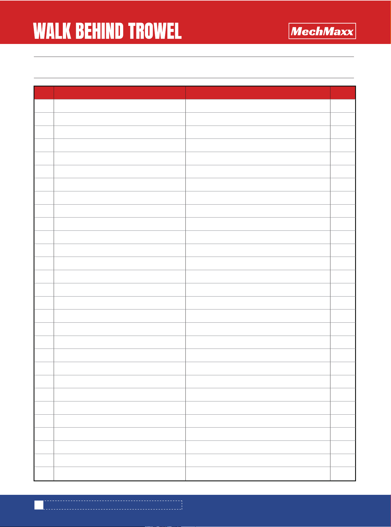
PARTS DIAGRAM (PT36H/PT36Z/PT46H/PT46Z GENERAL ASSEMBLY)
PARTS DIAGRAM (PT36H/PT36Z/PT46H/PT46Z GENERAL ASSEMBLY)
20
www.mechmaxx.com
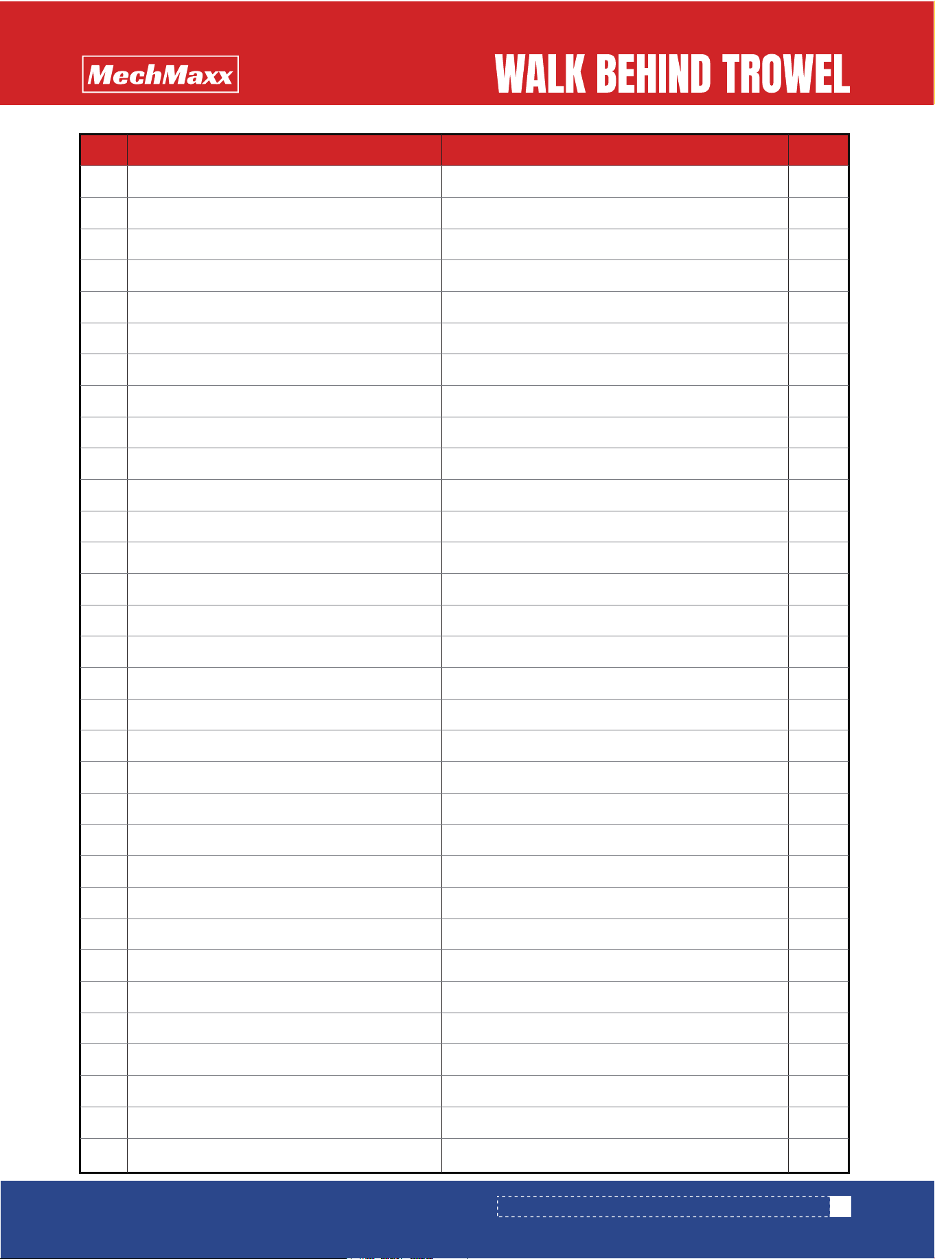
No. Description Qty.Specification
1
2
3
4
5
6
7
8
9
10
11
12
13
14
15
16
17
18
19
20
21
22
23
24
25
26
27
28
29
External Hexangon bolt
Spring Gasket
Conical flat gasket
Clutch
Key
Engine
Blade cover
External Hexangon bolt
Flat gasket
Engine support plate
Gasket
Locked nut
Stud bolt
Locked nut
External Hexangon bolt
Nut
Handle
Handle bar
Inner Hexangon bolt
Adjustable handle
Locked nut
Panel bearing
Aluminum bush
Adjustable arbor
Adjust bolt
Inner Hexangon bolt
Cylindrical pin
Wirerope
Wirerope support
M8*40
8
Ø8*30
5*50
M12*40
12
M12*40*4
M8
M8*40
M12
M16*120
M16
Include switch
M8*10
M8*12
51204
M8*10
Ø6*40
1
1
1
1
1
1
1
4
8
1
4
4
4
4
1
2
1
1
1
1
1
1
1
1
1
2
1
1
1
PARTS LIST (PT36H/PT36Z/PT46H/PT46Z GENERAL ASSEMBLY)
PARTS LIST (PT36H/PT36Z/PT46H/PT46Z GENERAL ASSEMBLY)
21
www.mechmaxx.com
External Hexangon bolt
Handle fixing seat
Flat gasket
Spring gasket
External Hexangon bolt
Nut
Flat gasket
Bolt
Nut
Shifting fork
External Hexangon bolt
External Hexangon bolt
Gasket of the pan
Inner Hexangon bolt
Blade
Disc pan
Belt
Belt cover support
Inner bolt
Belt cover
Flat gasket
Inner Hexangon bolt
Inner Hexangon bolt
Spring gasket
Enlarged flat gasket
Belt pulley
Shifting fork shaft
Splitpin
Pan 1
Bearing locating ring
Panel bearing
Pan 2
M10*80
10
10
M10*25
M10
10
M10*90
M10
M8*40
M10*25
M12*30
M8*16
6
M6*16
M8*20
8
Ø8*30
Ø3*30
51209
2
1
4
4
4
2
4
1
1
1
8
4
1
1
4
1
1
1
2
1
4
4
1
1
1
1
1
2
1
1
1
1
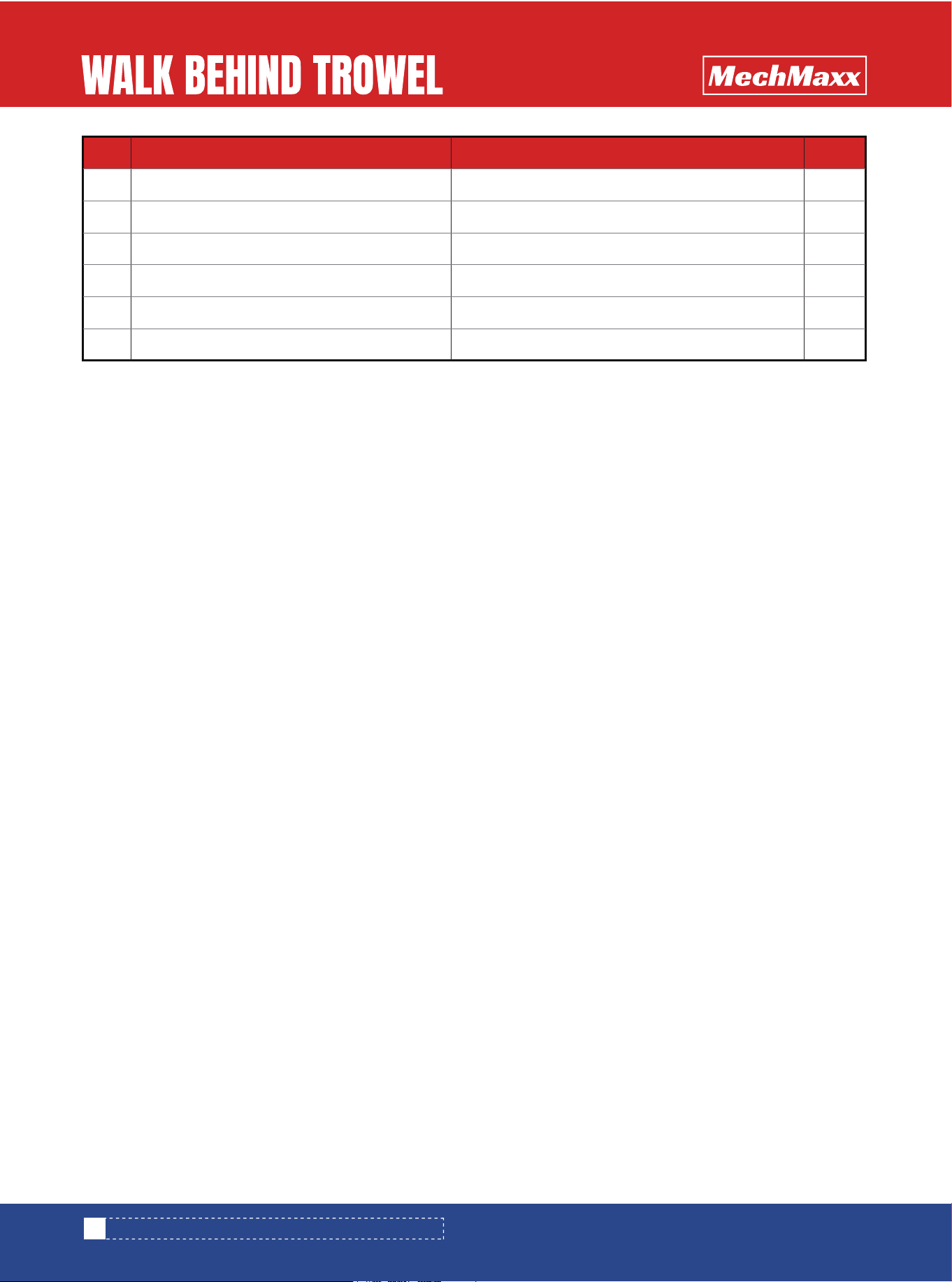
No. Description Qty.Specification
PARTS LIST (PT36H/PT36Z/PT46H/PT46Z GENERAL ASSEMBLY)
30
31
32
33
34
35
36
37
38
39
40
41
42
43
44
45
46
47
48
49
50
51
52
53
54
55
56
57
58
59
60
61
22
www.mechmaxx.com
PARTS LIST (PT36H/PT36Z/PT46H/PT46Z GENERAL ASSEMBLY)
Oil filling port
Blade shaft and elbow
torsion spring
Cross shaft
Inner bolt
Gearbox
M10*20
4
4
4
1
4
1
No. Description Qty.Specification
62
63
64
65
66
A