Operator’s Manual
www.mechmaxx.com
WARRANTY
Hot Water
Pressure Washer
Model:
HPW40H / HPW40HT / HPW40HBT
HPW40K / HPW40KT / HPW40KBT
HPW40D / HPW40DT / HPW40DBT

1
www.mechmaxx.com
CATALOGUE
CATALOGUE
INTRODUCTION
IMPORTANT SAFETY WARNINGS
REFERENCE GUIDE
SPECIFICATIONS
2
3
5
6
10
COMPONENT IDENTIFICATION
15
OPERATING INSTRUCTIONS
20
CHEMICAL APPLICATION
20
STORAGE & WINTERIZING
21
GENERAL MAINTENANCE
22
MAINTENANCE CHECKLIST
24
QUICK DIAGNOSTICS AND SOLUTIONS GUIDE
27
SERVICE MANUAL
39
WIRING DIAGRAMS
41
PARTS DIAGRAMS
43
PARTS LIST
45
PUMP DIAGRAMS
46
PARTS LIST
48
PUMP DIAGRAMS
49
PARTS LIST

2
www.mechmaxx.com
INTRODUCTION
INTRODUCTION
Thank You for Choosing Our Product
Thank you for selecting a high-quality product. We are pleased to welcome you among the many satisfied owners of our
cleaning machines. Years of engineering and innovation have gone into the development of these exceptional products,
using only top-quality components and materials throughout. Each machine is carefully tested and inspected before
leaving our facility to ensure reliable performance for years to come.
Maximizing Your Investment
To continue receiving optimal performance, it's important to remember that this machine represents a significant
investment. With proper care and maintenance, it will return that investment many times over. Like all mechanical
equipment, your machine requires proper operation and upkeep, as outlined in this manual, to ensure a long and
trouble-free life.
Expertly Designed and Tested
This manual has been prepared under the guidance of our engineering and service technicians. With years of experience
in designing, manufacturing, installing, and servicing our equipment, they have condensed their knowledge into this
document. They understand what information is needed to help you achieve the best performance from your pressure
washer. Please read the manual carefully.
Important Information and Safety Notices
This manual contains specific information for your pressure washer as well as for similar models. Please review any
additional manuals that have been included with your system, and be sure to follow all additional operating instructions
and safety notices. These are tailored to the high-quality components used in your machine and are a critical part of the
operating and maintenance procedures.
Our Commitment to You
Our goal is for you to be completely satisfied with the performance, quality, and service of our product. Should you need
to replace this machine in the future, we hope you will give us the opportunity to continue supplying equipment to your
company.
Important Reminders
· Read the manuals carefully before using the machine.
· Examine the machine and crate carefully for any shipping damage or missing parts.
· Report any shortages or damage claims promptly to the freight carrier or dealer.
3
www.mechmaxx.com
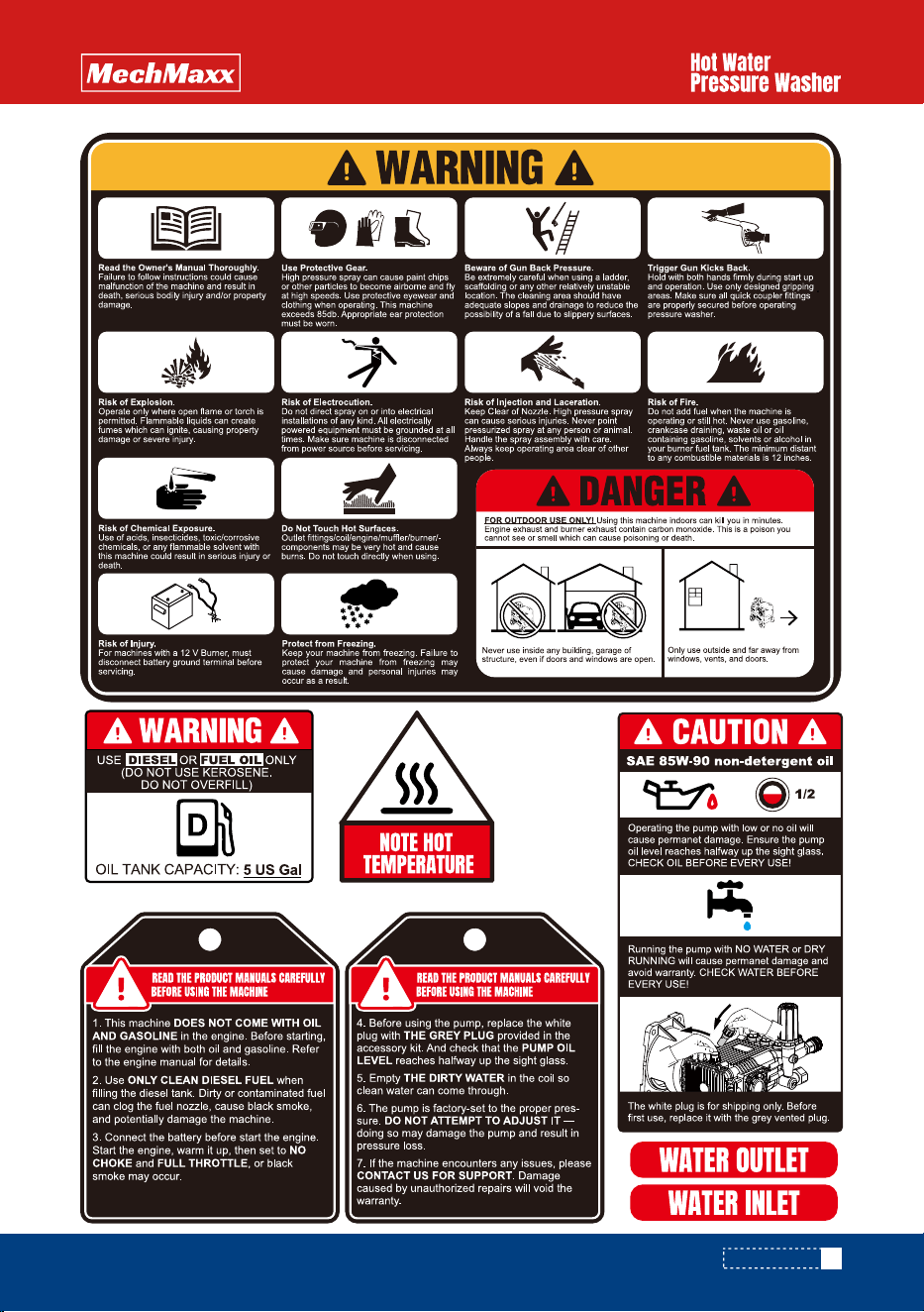
IMPORTANT SAFETY WARNINGS
IMPORTANT SAFETY WARNINGS
The safe operation of our pressure washing systems is the top priority. This can only be achieved by carefully following
the operation and maintenance instructions provided in this manual and any other accompanying documents.
This manual contains essential information about safety hazards, proper operation, and maintenance procedures related
to the equipment. It should always remain with the machine, even if the machine is resold.
ALL CAUTIONS AND SAFETY WARNINGS MUST BE FOLLOWED to prevent injury or damage to the equipment.
THIS EQUIPMENT SHOULD ONLY BE USED BY TRAINED OPERATORS and must always be monitored during
operation.
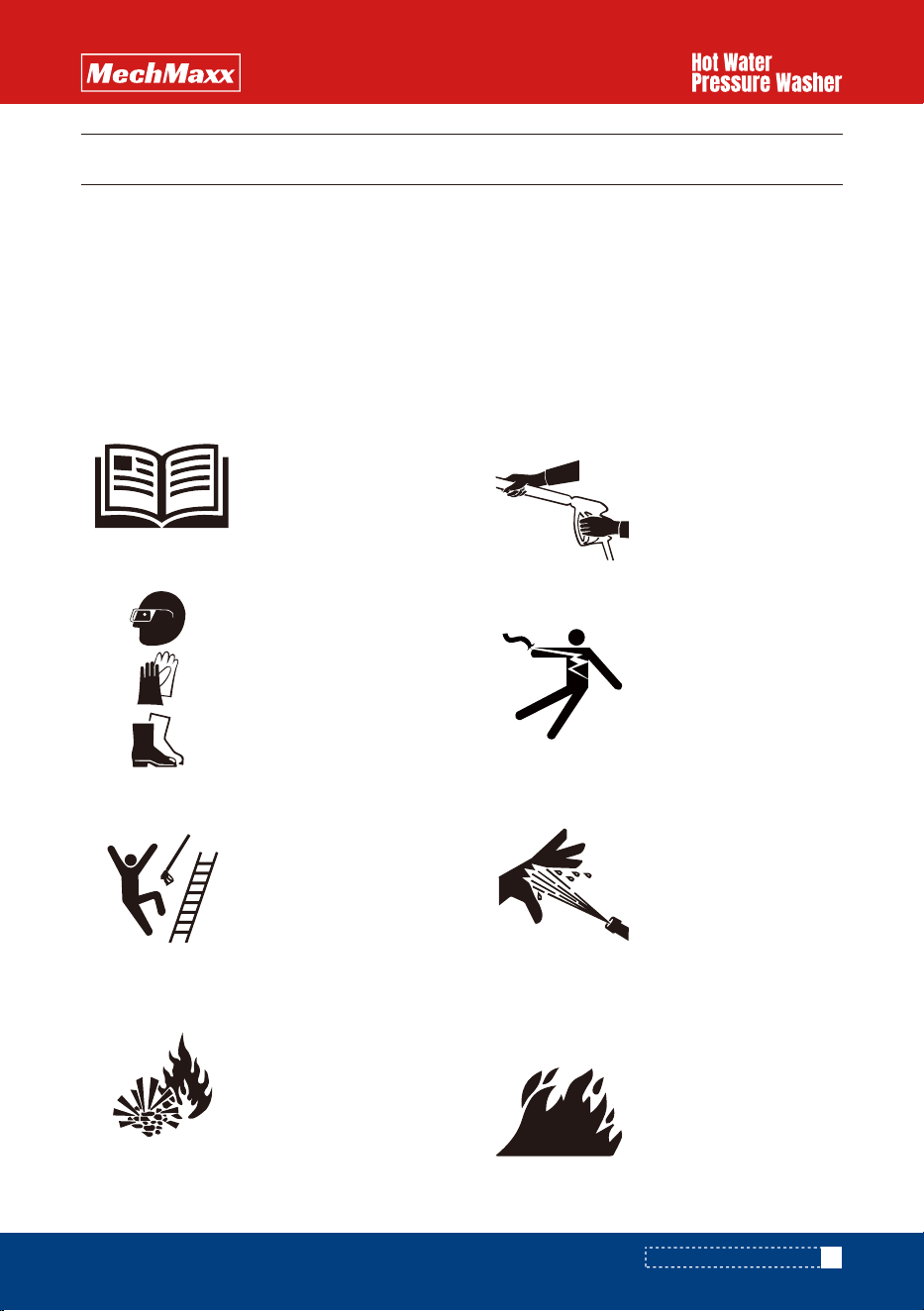
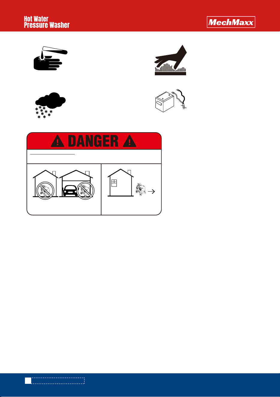
Read the Owner's Manual
Thoroughly.
Failure to follow instructions
could cause malfunction of the
machine and result in death,
serious bodily injury and/or
property damage.
Risk of Explosion.
Operate only where open flame
or torch is permitted. Flamma-
ble liquids can create fumes
which can ignite, causing
property damage or severe
injury.
Risk of Electrocution.
Do not direct spray on or into
electrical installations of any
kind. All electrically powered
equipment must be grounded
at all times. Make sure
machine is disconnected from
power source before servicing.
Risk of Injection and Lacer-
ation.
Keep Clear of Nozzle. High
pressure spray can cause
serious injuries. Never point
pressurized spray at any
person or animal. Handle the
spray assembly with care.
Always keep operating area
clear of other people.
Risk of Fire.
Do not add fuel when the
machine is operating or still
hot. Never use gasoline, crank-
case draining, waste oil or oil
containing gasoline, solvents
or alcohol in your burner fuel
tank. The minimum distant to
any combustible materials is
12 inches.
Use Protective Gear.
High pressure spray can cause
paint chips or other particles
to become airborne and fly at
high speeds. Use protective
eyewear and clothing when
operating. This machine
exceeds 85db. Appropriate ear
protection must be worn.
Beware of Gun Back Pres-
sure.
Be extremely careful when
using a ladder, scaffolding or
any other relatively unstable
location. The cleaning area
should have adequate slopes
and drainage to reduce the
possibility of a fall due to
slippery surfaces.
Trigger Gun Kicks Back.
Hold with both hands firmly
during start up and operation.
Use only designed gripping
areas. Make sure all quick
coupler fittings are properly
secured before operating
pressure washer.
4
www.mechmaxx.com
Never run the pump dry (without water or oil) or allow the pump to operate with the trigger gun released for more
than 2 minutes. Continuous operation when idle may cause pump damage.
Protect high-pressure hoses from sharp objects and vehicles. Always inspect hoses for damage before use to
avoid serious injury.
Do not allow acids, caustic substances, or abrasive fluids to pass through the pump.
Do not overextend or stand on unstable supports. Always maintain good footing and balance.
Do not operate the machine when fatigued or under the influence of alcohol, prescription medications, or drugs.
Some maintenance procedures require a certified technician (indicated throughout this manual). Do not
attempt these repairs unless you are qualified.
Risk of Chemical Exposure.
Use of acids, insecticides,
toxic/corrosive chemicals, or
any flammable solvent with
this machine could result in
serious injury or death.
Risk of Injury.
For machines with a 12 V
Burner, must disconnect
battery ground terminal before
servicing.
Protect from Freezing.
Keep your machine from freez-
ing. Failure to protect your
machine from freezing may
cause damage and personal
injuries may occur as a result.
Do Not Touch Hot Surfaces.
Outlet fittings/coil/engine/-
muffler/burner/components
may be very hot and cause
burns. Do not touch directly
when using.
IMPORTANT SAFETY WARNINGS
FOR OUTDOOR USE ONLY! Using this machine indoors can kill you in minutes.
Engine exhaust and burner exhaust contain carbon monoxide. This is a poison you
cannot see or smell which can cause poisoning or death.
Only use outside and far away from
windows, vents, and doors.
Never use inside any building, garage of
structure, even if doors and windows are open.
FOR OUTDOOR USE ONLY! Using this machine
indoors can kill you in minutes.
Engine exhaust and burner exhaust contain
carbon monoxide. This is a poison you cannot
see or smell which can cause poisoning or
death.
5
www.mechmaxx.com
REFERENCE GUIDE
REFERENCE GUIDE
PSI (Pounds per Square Inch):
Pressure washers are designed and rated to operate at a specific PSI. Operating at pressures exceeding the maximum
rating could result in damage to the unit and/or
SEVERE PERSONAL INJURY.
GPM (Gallons per Minute):
The orifice on the pressure wand assembly is selected to deliver the maximum GPM for your machine.
BTU (British Thermal Unit):
It represents the amount of work or energy required to increase the temperature of one pound of water by one degree
Fahrenheit.
Pressure Wand Assembly:
This refers to the gun, wand, and nozzle.
Pump:
The pump moves water through the system and delivers it to the pressure wand assembly.
Unloader Valve:
A valve located at the head of the pump that unloads water back into the bypass when the trigger gun is released. It
also reduces the load on the pump when the gun is off.
Chemical Injection System:
Mixes cleaners or cleaning solvents with the water to improve cleaning effectiveness.
Pump Oil:
The oil used to lubricate the pump’s operation.
Use SAE 85W/90 Non-Detergent Oil.
Engine Oil:
Gasoline engines require appropriate lubricant.
Use SAE 10W/30 Detergent Oil
.
Burner Assembly:
A device used to change fuel into heat energy. The burner heats the water in hot water pressure washers. It is located
under the coil and may be powered by furnace oil or diesel fuel.
Maximum Working Pressure:
The water heater coils are designed to operate safely at the normal working pressure. Each machine is equipped with a
safety pressure relief valve to prevent over-pressurization of the high-pressure system. This is a critical safety device
and must not be tampered with.
Temperature Control:
The water heater is equipped with a temperature control that shuts down the burner if the outlet temperature becomes
excessive due to insufficient water flow through the heater coil.
12-Volt DC Battery (if equipped):
The 12-volt battery powers the engine's electrical starting system. Once the engine starts, the system charges the
battery and operates the burner. Regular replacement of the 12-volt battery is necessary to maintain consistent perfor-
mance.
6
www.mechmaxx.com
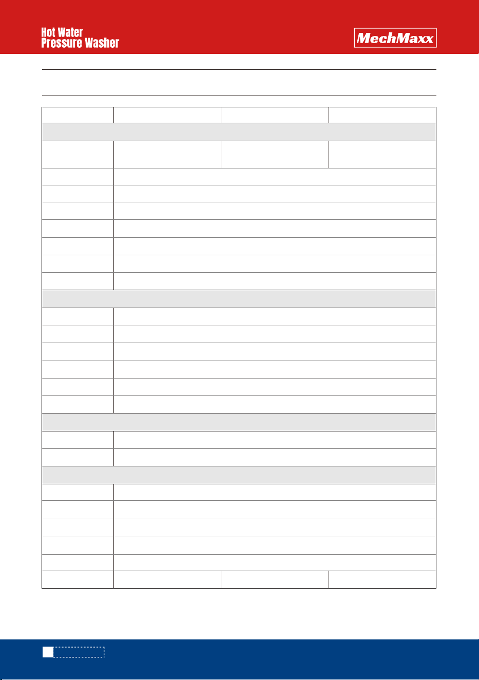
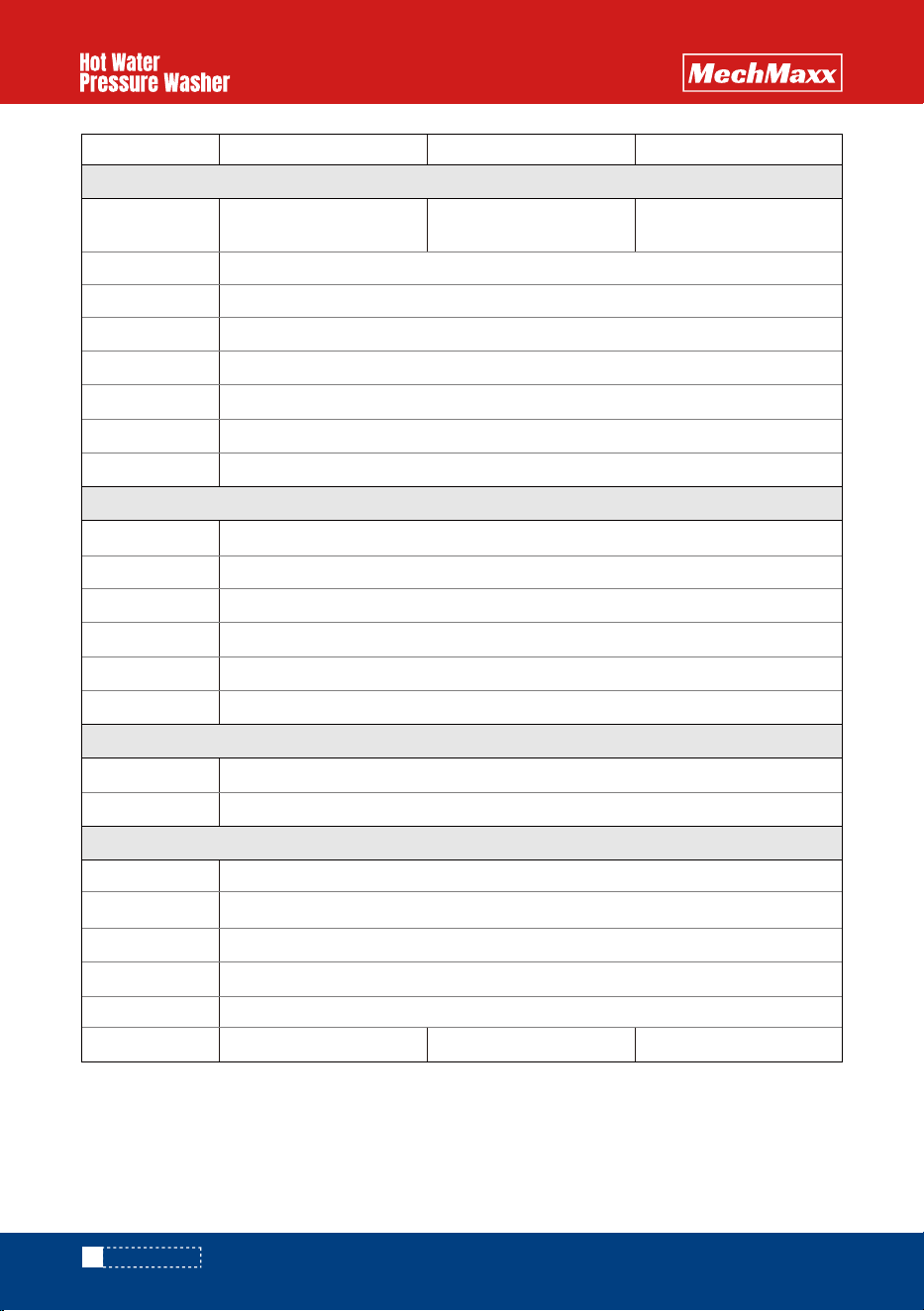
SPECIFICATIONS
SPECIFICATIONS
3500-4000 PSI
4.0 GPM
350,700 BTU
200℉ (93℃)
12V
5 US gal (19L) Diesel
Direct
Triplex Plunger Pump / Oil Bath Crankcase
SAE 85W/90 Non Detergent
3/8" x 50' High Pressure Hose
0°, 15°, 25°, 40° and Chemical
36" Spry Gun & Wand Assembly
Included
Included
Not Included Included Included
HONDA GX390
Single Cylinder, 4 Stroke, Air-Cooled, OHV
389 cc; 11.7 HP
Electric Start (battery included)
Clean, fresh, unleaded gasoline
SAE 10W-30
Portable with 13"
Pneumatic Tires
Truck Skid Mount with
175 gal Water Tank
Truck Skid Mount with
245 gal Water Tank
HPW40H HPW40HT HPW40HBT
Specifications
Model
Pressure Range
Machine Type
Engine
Pump
Standard Accessories
Flow Rate
BTU Per Hour
Max Temperature
Igniter
Burner Fuel
Drive
Engine Model
Engine Type
Displacement
Start Type
Engine Fuel
Engine Oil
Pump Type
Pump Oil
Hose
Nozzles
Spry Gun & Wand
Hose Reel
Siphon Tube
LED Work Lights
7
www.mechmaxx.com
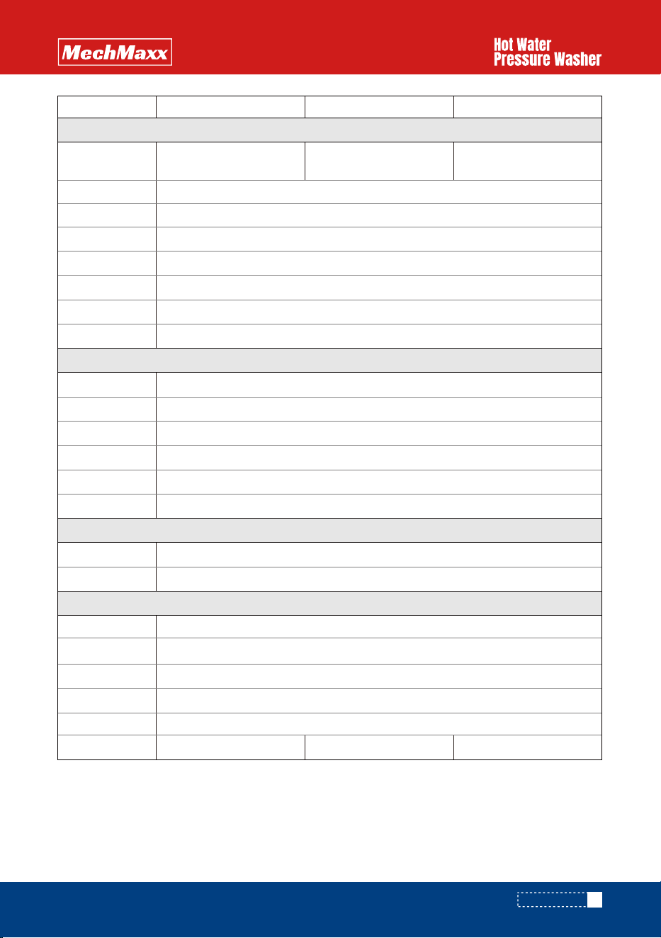
SPECIFICATIONS
3500-4000 PSI
4.0 GPM
350,700 BTU
200℉ (93℃)
12V
5 US gal (19L) Diesel
Direct
Triplex Plunger Pump / Oil Bath Crankcase
SAE 85W/90 Non Detergent
3/8" x 50' High Pressure Hose
0°, 15°, 25°, 40° and Chemical
36" Spry Gun & Wand Assembly
Included
Included
Not Included Included Included
KOHLER CH440
Single Cylinder, 4 Stroke, Air-Cooled, OHV
429 cc; 14 HP
Electric Start (battery included)
Clean, fresh, unleaded gasoline
SAE 10W-30
Portable with 13"
Pneumatic Tires
Truck Skid Mount with
175 gal Water Tank
Truck Skid Mount with
245 gal Water Tank
HPW40K HPW40KT HPW40KBT
Specifications
Model
Pressure Range
Machine Type
Engine
Pump
Standard Accessories
Flow Rate
BTU Per Hour
Max Temperature
Igniter
Burner Fuel
Drive
Engine Model
Engine Type
Displacement
Start Type
Engine Fuel
Engine Oil
Pump Type
Pump Oil
Hose
Nozzles
Spry Gun & Wand
Hose Reel
Siphon Tube
LED Work Lights
8
www.mechmaxx.com
SPECIFICATIONS
3500-4000 PSI
4.0 GPM
350,700 BTU
200℉ (93℃)
12V
5 US gal (19L) Diesel
Direct
Triplex Plunger Pump / Oil Bath Crankcase
SAE 85W/90 Non Detergent
3/8" x 50' High Pressure Hose
0°, 15°, 25°, 40° and Chemical
36" Spry Gun & Wand Assembly
Included
Included
Not Included Included Included
ZONSEN GB460
Single Cylinder, 4 Stroke, Air-Cooled, OHV
459 cc; 15 HP
Electric Start (battery included)
Clean, fresh, unleaded gasoline
SAE 10W-30
Portable with 13"
Pneumatic Tires
Truck Skid Mount with
175 gal Water Tank
Truck Skid Mount with
245 gal Water Tank
HPW40D HPW40DT HPW40DBT
Specifications
Model
Pressure Range
Machine Type
Engine
Pump
Standard Accessories
Flow Rate
BTU Per Hour
Max Temperature
Igniter
Burner Fuel
Drive
Engine Model
Engine Type
Displacement
Start Type
Engine Fuel
Engine Oil
Pump Type
Pump Oil
Hose
Nozzles
Spry Gun & Wand
Hose Reel
Siphon Tube
LED Work Lights
9
www.mechmaxx.com
SPECIFICATIONS
10
www.mechmaxx.com
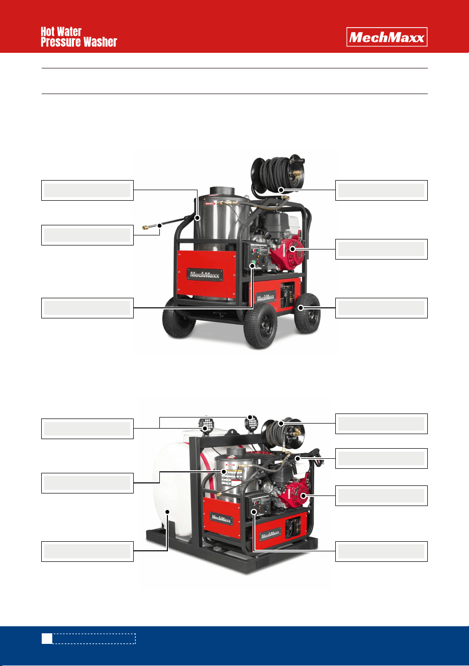
COMPONENT IDENTIFICATION
COMPONENT IDENTIFICATION
HPW40H / HPW40K / HPW40D
HPW40HT / HPW40KT / HPW40DT
This section provides an overview of the key components of your pressure washer. Familiarizing yourself with these
parts will help ensure proper operation, maintenance, and troubleshooting.
Engine
13" Pneumatic Tires
50' Hose with Reel
Spray Gun & Wand
Engine
50' Hose with Reel
Control Panel
Control Panel
Spray Gun & Wand
Heating Coil
175 Gal Water Tank
LED Work Lights
Heating Coil
11
www.mechmaxx.com
*The pump is factory-set to the
proper pressure. Do not attempt
to adjust it — doing so may
damage the pump and result in
pressure loss.
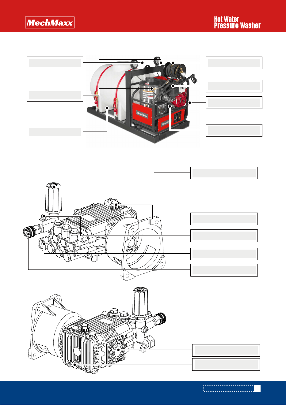
High Pressure Pump Assembly
COMPONENT IDENTIFICATION
HPW40HBT / HPW40KBT / HPW40DBT
Spray Gun & Wand
Engine
Control Panel
50' Hose with Reel
245 Gal Water Tank
LED Work Lights
Heating Coil
Pressure Adjusting Handle
Oil Cap
Chemical Injector
Water Inlet
Oil Sight Glass
Oil Drain Plug
Water Outlet
12
www.mechmaxx.com
COMPONENT IDENTIFICATION
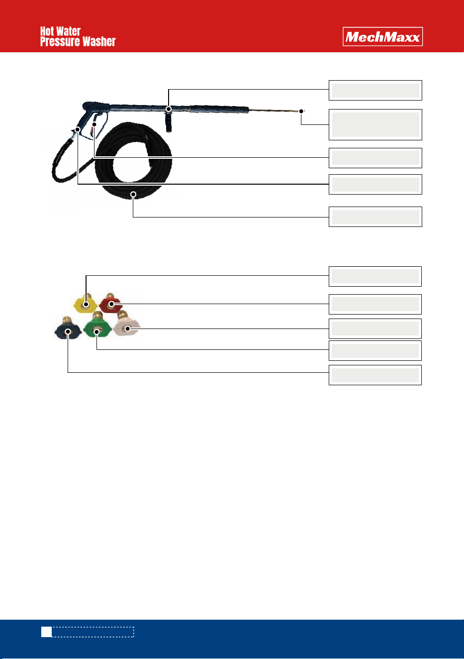
Spray Gun & Wand Assembly
Nozzles
Nozzle Quick
Coupler
Trigger
Spray Gun
High Pressure Hose
Wand
15° Yellow
0° Red
40° White
25° Green
Chemical Black
13
www.mechmaxx.com
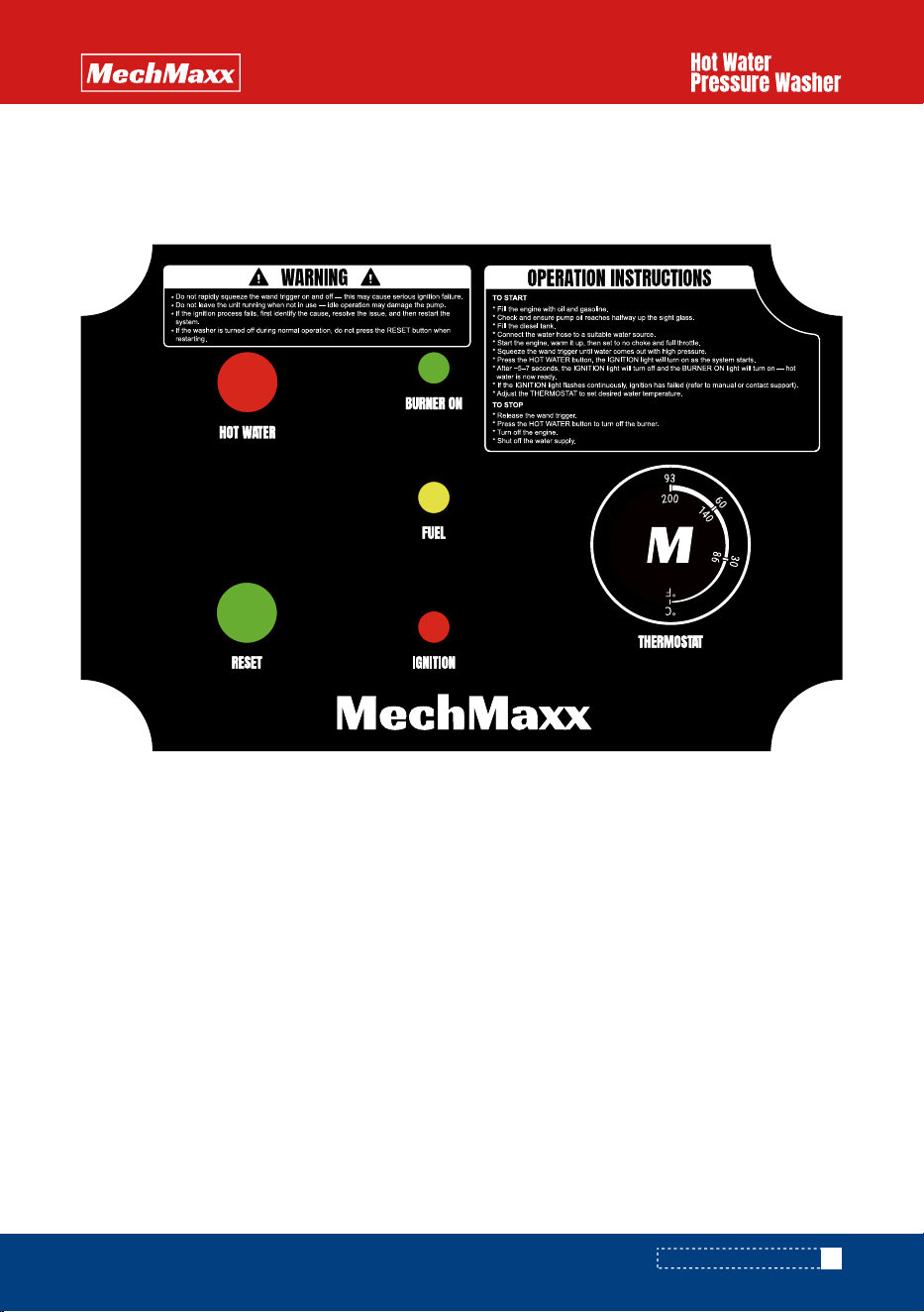
1. HOT WATER: Hot Water Button Switch
-To use hot water for cleaning, press the hot water button. This switch has a self-locking function. Press once to turn
on, and press again to turn off.
2. RESET: Reset Button Switch
-If the washer was turned off during normal operation, there is no need to press the RESET button when starting the
machine again.
-If the machine fails to ignite, or ignites but does not produce a flame successfully, the IGNITION light will start flash-
ing. Troubleshoot to resolve the issue. Once the problem is fixed, press the RESET button for about 3 seconds until the
light stops flashing before restarting the machine.
Important Note:
To avoid accidental incorrect operation during troubleshooting, the electrical control center is designed with a memory
function. The machine can only start working properly after the RESET button is pressed following successful trouble-
shooting.
3. THERMOSTAT: Temperature Control Switch
-This switch controls the water temperature.
Switch:
This high pressure washer is a hot and cold machine. If you do not use hot water, do not operate the electrical control
center
Electrical Control Center:
Important Note:
COMPONENT IDENTIFICATION

14
www.mechmaxx.com
1. BURNER ON
-When the machine ignites and successfully produces a flame, the combustion chamber is working properly, and the
BURNER ON light will turn green.
2. FUEL
-If the diesel fuel is low, the FUEL light will turn yellow.
3. IGNITION
When you start the engine:
-If you do not need hot water, do not turn on the HOT WATER switch. Simply pull and hold the trigger to get high-pres-
sure water.
-If you need hot water, turn on the HOT WATER switch. Then, pull and hold the trigger on the wand until you feel
high-pressure water. The IGNITION light will turn on, indicating that the ignition process has started. Once ignition is
successful and the flame is on, the burner will stop automatically.
-If the IGNITION light starts flashing, it means ignition has failed or the flame has gone out. In this case, stop the
machine immediately and proceed with troubleshooting.
Indicator Lights:
COMPONENT IDENTIFICATION
OPERATING INSTRUCTIONS
15
www.mechmaxx.com
1. Pre-Start Maintenance Inspection
Before operating the machine, perform a pre-start maintenance inspection on all applicable systems. This is essential
for the safe, effective, and efficient operation of the pressure washer. You will achieve optimal performance only if
these instructions and inspections are followed. Any indication that the pressure washing system was not operated or
maintained according to these instructions may void the manufacturer’s warranty.
Location:
-Ensure the machine is installed in an area with sufficient air ventilation to support the combustion of oil in the burner.
Controls:
-Verify that all controls are turned to the off position.
Electrical Components:
-Visually inspect all electrical components to ensure they are in good condition and show no signs of exposure, break-
age, or splicing.
Hoses, Nozzles, and Guns:
-Visually inspect all hoses, nozzles, and guns to ensure they are in good condition.
If replacements are necessary, they must be rated to withstand the machine’s operating pressure and temperatures.
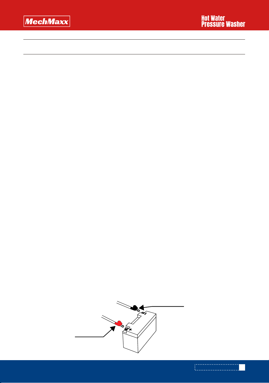
2. Battery Connections (Battery Included with the Machine)
The pressure washer is equipped with a 12-volt standard battery. Follow these steps for connecting and disconnecting
the battery:
-Connecting Sequence
Connect the red cable to the positive (+) terminal of the battery.
Then, connect the black cable to the negative (-) terminal of the battery.
(The black cable is pre-installed on the
negative terminal)
-Disconnecting Sequence
First, disconnect the black cable from the negative (-) terminal of the battery.
Next, disconnect the red cable from the positive (+) terminal of the battery.
WARNING:
Always disconnect the black, negative (-) battery cable first and connect it last.
WARNING:
Always wear eye protection and protective clothing when handling batteries.
WARNING:
Never smoke or work near sparks or other ignition sources.
WARNING:
Never touch both battery terminals simultaneously with your hand or any non-insulated tools.
WARNING:
If battery acid contacts skin or clothing, immediately flush with water and neutralize with baking soda. If it
enters the eye, immediately flush the eye with running cold water for at least 15 minutes and seek immediate medical
attention.
Red Positive
Black Positive
OPERATING INSTRUCTIONS
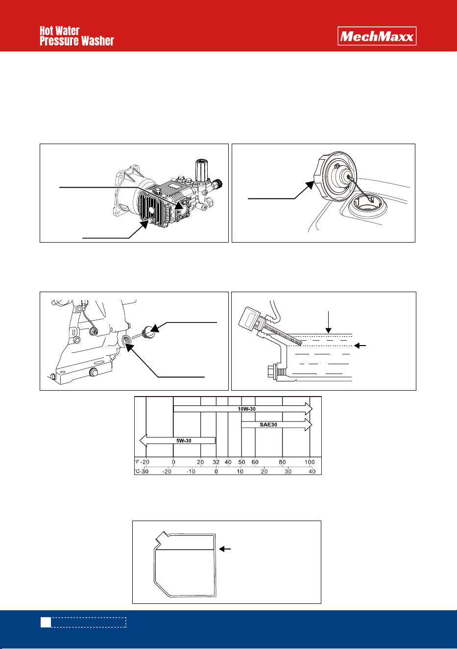
3. Pump Oil (The pump is pre-filled with oil, but you still need to check the oil level)
-Level the pressure washer and check the oil level using the dipstick. If the oil level is low, add the correct oil to bring it
up to the proper level.
Use SAE 85W/90 Non-Detergent Oil.
. Do not overfill.
4. Engine Fuel
-The engine is a 4-cycle and requires regular octane, unleaded fuel. Do not use mixed fuel. Refer to the engine operation
manual included with your pressure washer for specific details.
5. Engine Oil
-The engine requires
10W-30 detergent oil
. Refer to the engine operation manual included with your pressure washer
for specific details.
6. Burner Fuel
Use fresh, high-quality #2 fuel oil or diesel. Fill the tank to a maximum of 1 inch below the filler neck to allow for expan-
sion. Do not overfill the burner oil tank.
16
www.mechmaxx.com
OPERATING INSTRUCTIONS
Oil Filler Cap /
Dipstick
Oil Fill Hole
(bottom edge)
Oil Sight Glass
Oil Drain Plug
Upper Limit
Fuel Filler Cap
Lower Limit
Maximum fuel level
17
www.mechmaxx.com
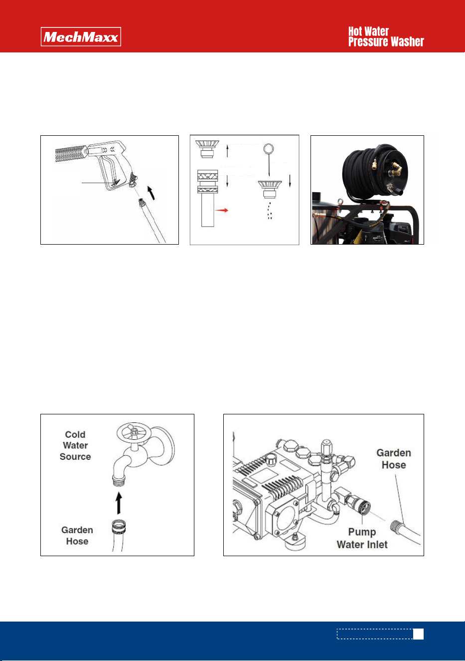
7. Install Hose Reel and Connect High-Pressure Water Hose
-Use a high-pressure hose to connect the hot water outlet to the hose reel.
-Install the 50' high-pressure hose onto the hose reel, then attach the hose (with a quick coupler) to the spray gun.
-Ensure that all quick disconnect connections are tightly locked. To confirm they are secure, apply a sharp pull on the
hose.
8. Attach Wand Nozzle Specific to Task Requirements
-Quick Coupling Operation:
-Pull back the sleeve on the quick coupler.
-Insert the male end into the nozzle quick coupler.
-Release the sleeve and confirm the connection by pulling on the nozzle.
9. Attach Water Source to Pump Water Inlet
-The water source must be connected using a high-quality, standard garden-type hose (minimum 5/8" ID).
-Connect the fitting of the hose to the pump inlet fitting. Ensure that the inlet screen/filter is intact and properly fitted.
-Turn on the water source.
The water supply must be sufficient, and the pressure must be between 20–60 PSI to
ensure proper and safe operation.
-If using a well water supply, ensure that the water level does not fall more than 10 feet below the pump.
-Ensure water is flowing from the nozzle when the trigger gun is pulled to deplete the system of air.
10. Start Gas Engine
-Refer to the instructions in the engine manual for proper startup procedures.
Ensure the engine exhaust is not
directed toward any flammable materials to prevent fire hazards.
OPERATING INSTRUCTIONS
Spray
Gun
High Pressure
Hose
Safety
Latch
Wand
Needle
Pressure Nozzle
Quick Coupler
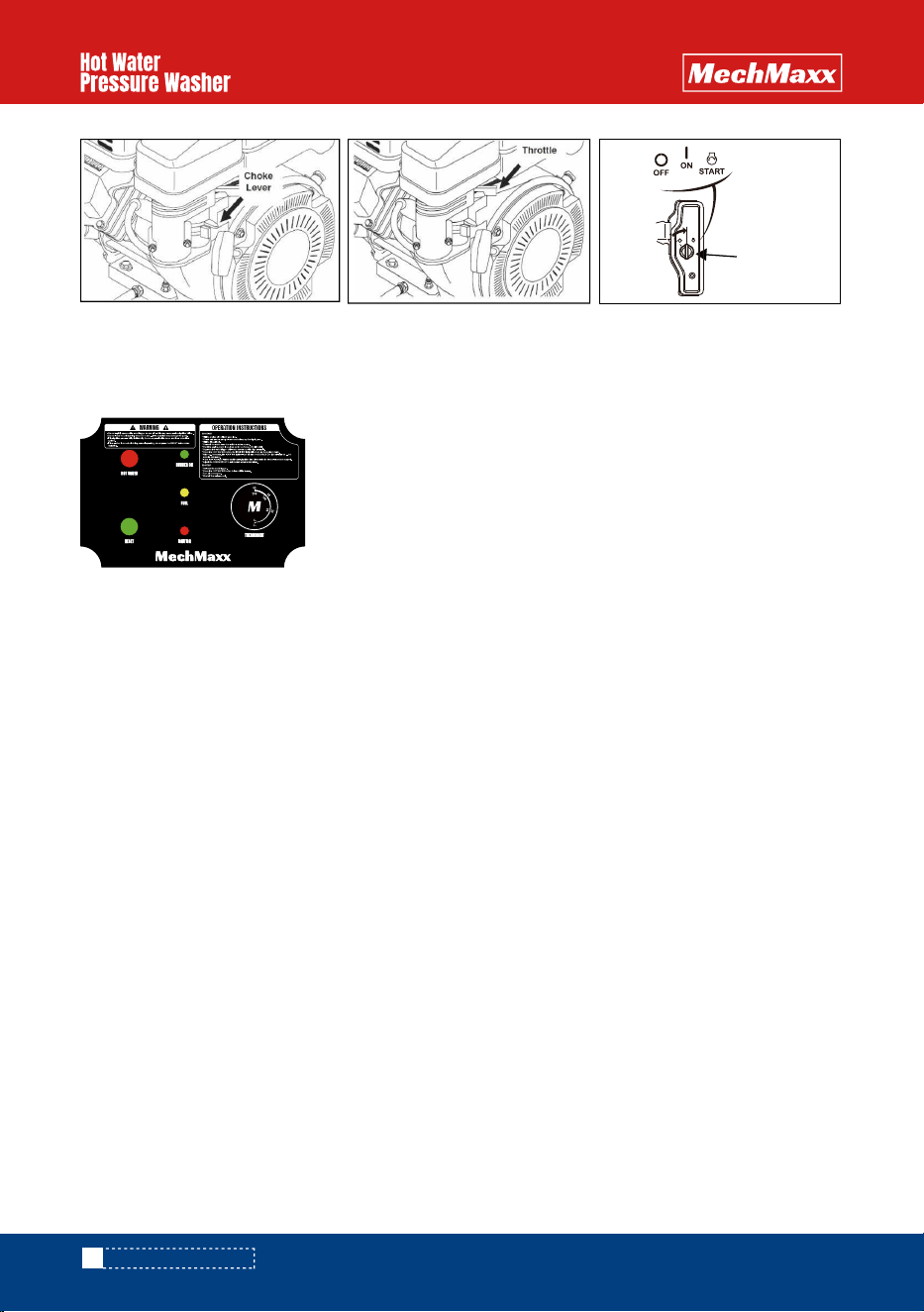
11. Burner Operation
-Ensure water is flowing through the water heater coil before turning on the HOT WATER switch. Set the thermostat to
the desired temperature. The burner will ignite and continue to operate as long as there is sufficient water flow to
satisfy both the pressure switch and the temperature control.
Warning: If You Experience Ignition Failure
Do not attempt to restart the burner! Excess fuel and vapors may have accumulated, and the combustion chamber
could be hot. The unit must cool down before any attempt to restart the burner can be made.
Warning: Condensation on Coil
When cold water is being pumped through the heater coil and the burner is firing, condensation may form on the coil and
drip into the burner compartment. This is especially noticeable on cold, humid days, and may give the false appearance
of a leaking coil. A leaking coil or system will be evident if the pump keeps cycling with the trigger released. The pump
head pressure should read 0.
Electrically Operated Burners
-These models generate 12V from the gasoline engine to provide the necessary power for the burner. The power supply
must be adequate for your specific unit. Check the data plate for your machine’s specific requirements.
12. Pressure Adjustment
-The pressure regulator (unloader valve) is located on the pump. It controls the pressure generated by the pressure
washer.
The pump is factory-set to the proper pressure. Do not attempt to adjust it — doing so may damage the pump and
result in pressure loss.
18
www.mechmaxx.com
Engine
Switch
OPERATING INSTRUCTIONS
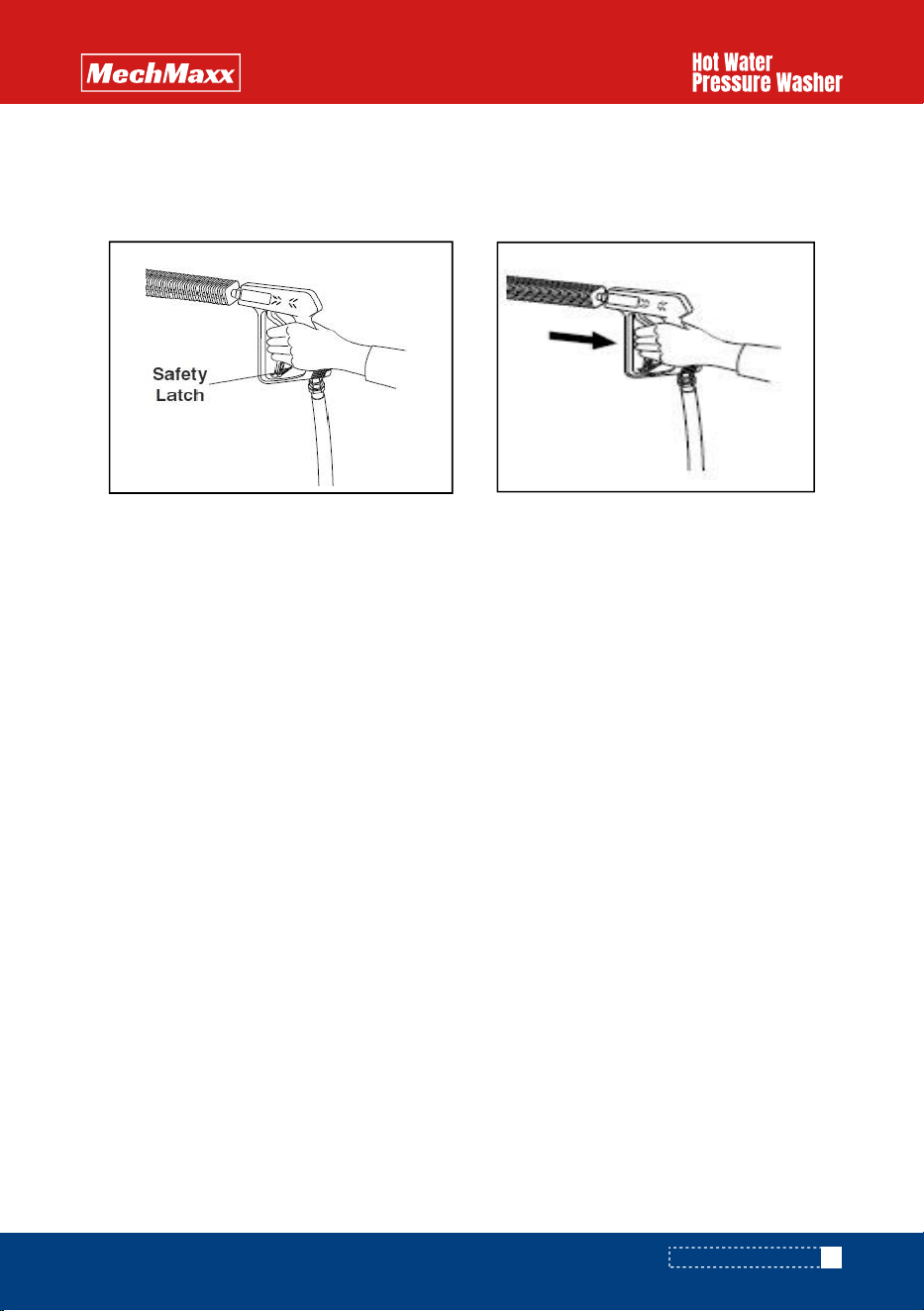
13. Start Cleaning Operation
-You are now ready to begin cleaning. Pull the trigger on the pressure wand assembly to start the cleaning process. To
stop the pressurized water, release the trigger. Do not leave the unit running when not in use to prevent unnecessary
wear and damage.
14. To Stop Burner Operation
-Press the HOT WATER switch again to turn off the burner. Run the pump for two minutes with the trigger gun pulled to
allow the coil to cool down. Squeeze and release the trigger a second time to relieve pressure from the pump system.
15. Prior to Storage
-Inspect the pressure washer for any damage or required maintenance. If your machine will be exposed to cold weather,
refer to the winterization instructions for the pump and coil found in this manual. If possible, do not leave the unit
outside in harsh weather conditions.
16. Warning: Pump Damage
-Do not leave the unit running when not in use. Continuous operation when idle may cause pump damage.
19
www.mechmaxx.com
OPERATING INSTRUCTIONS

CHEMICAL APPLICATION
STORAGE & WINTERIZING
Downstream Chemical Injection: Standard (Direct Drive Units) High Pressure Soap
NOTE:
Do not remove the backflow preventer, as chemicals may flow back into the potable water source. For stan-
dard chemical injection, ensure the black nozzle is properly fitted at the end of the wand. The chemical injec-
tor will not function if the nozzle is not in place.
1. Chemical Preparation
-Select a detergent or chemical that best suits your cleaning task. Prepare the chemical dilution according to the
manufacturer's instructions. Adjust the volume of chemical being used at the valve located on the chemical injector.
2. Insert the Intake Hose
-Insert the intake hose (located on the chemical injector at the pump) into the chemical being used.
3. Fit the Nozzle
-For standard units, fit the black nozzle onto the wand. For dual wand systems, turn the adjustment knob on and adjust
it to the required flow rate. For high-pressure soap systems, the black nozzle is not needed—use one of the other wand
nozzles.
4. Apply Chemical
-To apply the chemical, engage the trigger on the pressure wand assembly. Turn the chemical injector’ s nipple to adjust
the flow. For high-pressure soap systems, open the ball valve and engage the trigger.
5. Chemical Application
-The chemical will now be applied through the pressure wand assembly. It will take 5–15 seconds for the chemical to
travel to the spray nozzle. Adjust the chemical volume as needed at the chemical injector.
6. Best Practices for Chemical Application
-For best results, apply the chemical from bottom to top, allowing proper penetration time before rinsing. Do not allow
the chemical to dry on the surface. Rinse from bottom to top, then top to bottom to ensure thorough removal.
Procedure for Storing the Pressure Washing Unit in Freezing Temperatures.
The following procedure must be
used when storing the pressure washer in temperatures below freezing:
1. Drain the System
-All water must be drained or blown out using compressed air. Connect a short piece of male-fitted ½” garden hose to
the female inlet on the pump.
2. Prepare Anti-Freeze Solution
-Place the open end of the hose into a wide-mouthed container filled with full-strength, winter-rated windshield washer
fluid or anti-freeze rated for a minimum of -40°C.
3. Connect the Pressure Wand Assembly
-Attach the pressure wand assembly to the system.
4. Run the System
-Start the engine and engage the trigger on the pressure gun. Operate the system until the fluid running through the
system matches the color of the windshield washer fluid. Your machine is now prepared for cold weather storage.
5. Disconnect and Final Steps
-Disconnect the fluid supply and blow out the system with compressed air. Cap the end of the hose to seal it.
20
www.mechmaxx.com
CHEMICAL APPLICATION

GENERAL MAINTENANCE
NOTE: Burner repairs must only be performed by authorized and trained professionals.
Oil Filter Cartridge
-Replace the oil filter cartridge every year to prevent fuel contamination and clogging of the fuel pump and nozzle.
Nozzle Replacement
-The nozzle should be replaced at least once a year or more frequently (e.g., twice a year) if the machine is used daily or
if poor combustion is observed.
Final Burner Adjustments
-Fuel Pressure Adjustment: Adjust the fuel pressure to control the water temperature. To increase the output tempera-
ture, tighten the fuel pressure adjustment screw slightly. Air Band Adjustment: Adjust the air band for combustion
efficiency. A combustion test kit should be used for these final adjustments. Refer to the SPECIFICATIONS chart for the
correct burner oil pressure for your model. Do not exceed the specified pressure.
If the Burner Floods with Oil
-Run the machine with the heat on until all excess oil is burned off (this can take up to a couple of hours). If excess oil
is not properly dealt with, the ceramic casing may absorb it, creating a fire hazard. DO NOT leave the machine unattend-
ed while it is flooded with oil.
General Maintenance and Care
-Winterizing the Water Heater. If the water heater will be exposed to freezing temperatures, winterize the system
according to the procedure outlined in the Winter Pump/Coil Protection section. Alternative methods may not provide
full protection. Damage from freezing is not covered under warranty.
Water Quality
If local water is high in mineral content, consider using a water softener. The benefits of soft water include:
-Prevents scale buildup in the heater coil.
-Cleans better with less detergent.
-Reduces streaking on painted surfaces and glass when rinsing.
NOTE: Descaling of the heater coil must only be done by authorized and trained professionals.
The most effective way to acidize the coil is by using a circulation pump capable of handling acids.
-Prepare the Acid Solution: Fill a plastic container with a suitable acid diluted with water to the desired strength.
-Set Up the Circulation Pump: Connect the discharge from the circulating pump to the hot water outlet on the water
heater using a suitable hose. Connect the pump inlet to the acid container with a suction hose, using the return hose to
funnel the solution back into the acid container.
-Acid Circulation: As the acid dissolves the scale, it becomes neutralized. Every 5 minutes, add more acid to the
container until all scale is removed from the coil.
-Flush the Coil: After descaling, thoroughly flush the coil with clean water to remove any remaining acid and residue.
21
www.mechmaxx.com
Burner Maintenance
Descaling the Heater Coil
GENERAL MAINTENANCE
Daily:
- Check the oil level and adjust as needed.
- Inspect the quality of the oil.
- Check the pump for oil and/or water leaks.
- Clean and inspect the inlet filters.
Weekly:
- Inspect all fittings, components, hoses, connections, and nozzles for damage, loose parts, or leaks.
Replace any damaged or worn parts as needed.
Oil Change and Component Replacement Recommendations:
- Change the pump oil after the first 50 hours of use and every 500 hours thereafter. Use SAE 85W/90 Non-Detergent
Oil for this pump.
- Replace other pump components as needed.
Daily:
- Check the oil level and adjust as needed.
- Inspect the quality of the oil.
- Inspect the air cleaner element.
Weekly:
- Inspect engine components for damage, loose parts, or leaks.
Oil Change and Component Replacement Schedule:
- Change the engine oil after the first 5 hours of use, and then every 100 hours thereafter. Use 10W-30 engine oil.
- Replace the spark plug every 100 hours.
- Change the air cleaner element every 100 hours.
- Check the fuel filters every 300 hours.
- Replace other engine components as needed.
Pump Maintenance
Gasoline Engine Maintenance
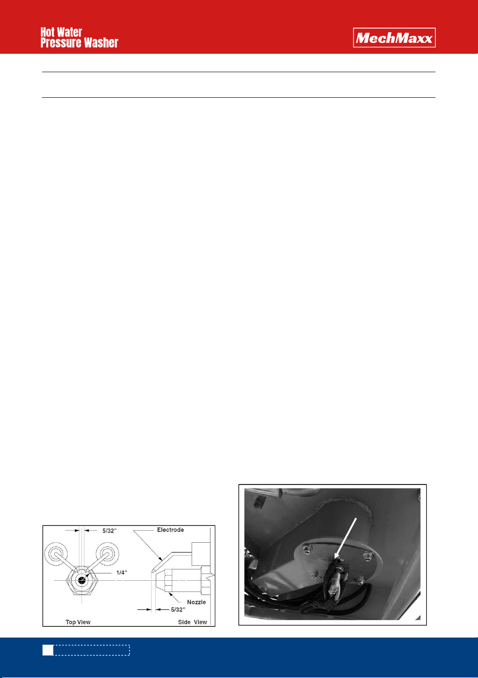
Ignition System Maintenance
1. Electrode Setting: (See below.)
-Periodically check wiring connections. If needed,
adjust the electrodes using the provided diagram.
MAINTENANCE CHECKLIST
22
www.mechmaxx.com
Ignition Disc
MAINTENANCE CHECKLIST
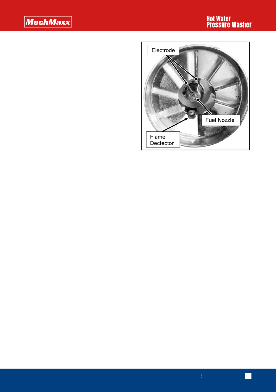
2. Flame Detector:
-The flame detector is a crucial component of the
ignition system, as it determines whether ignition is
successful. When the machine starts, stops, or fails
to ignite, black smoke or soot may accumulate on
the glass cover of the flame detector. If the glass
cover becomes covered with soot, the flame detec-
tor will no longer function properly, and the machine
will trigger an alarm. To maintain proper operation,
the flame detector should be cleaned regularly. Use
a soft cloth to wipe off any soot or bituminous coal
from the surface.
Cleaning Steps:
-Lift the machine and remove the ignition.
-Clean the flame detector’ s surface to remove soot
or bituminous coal.
www.mechmaxx.com
23
MAINTENANCE CHECKLIST
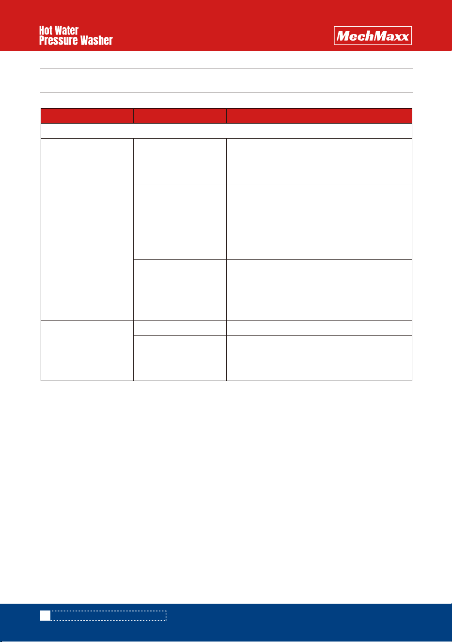
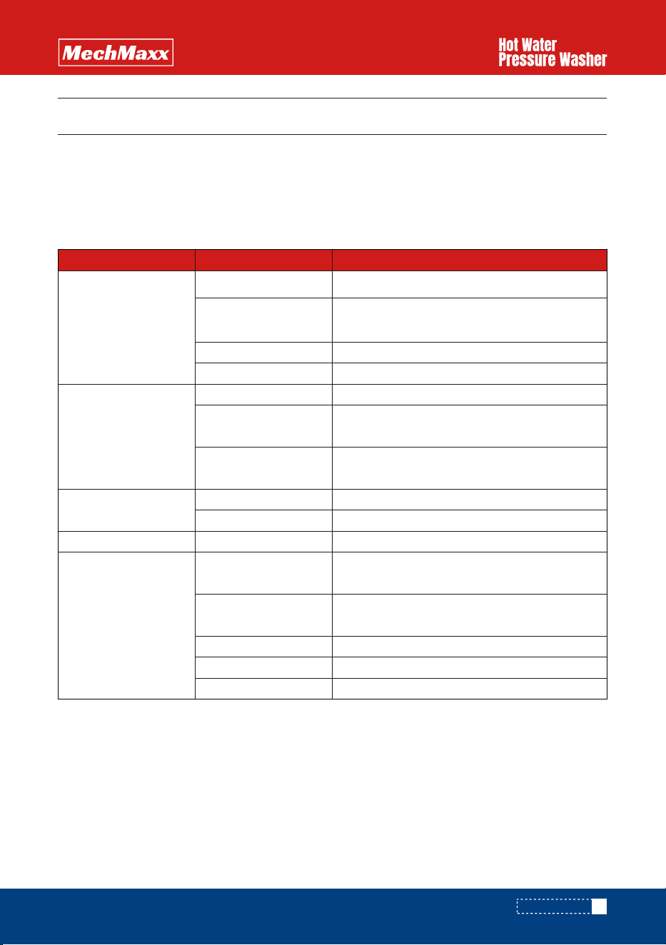
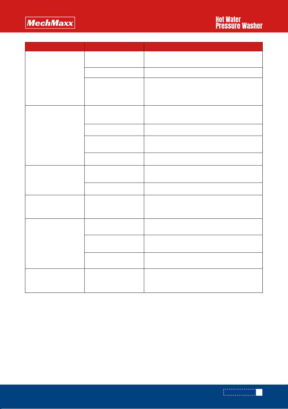
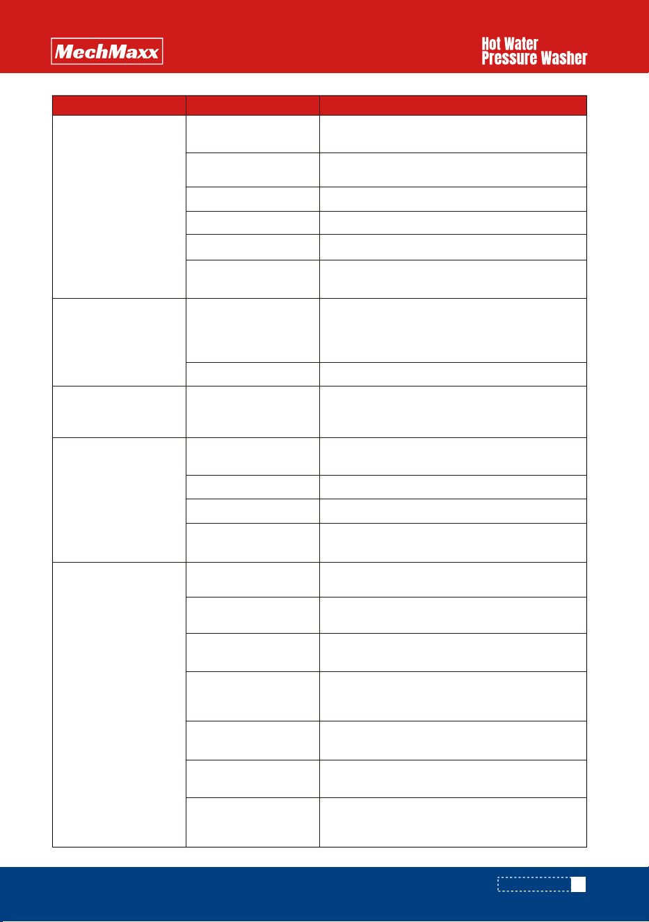
QUICK DIAGNOSTICS AND SOLUTIONS GUIDE
POSSIBLE CAUSES
PRESSURE
SOLUTIONSPROBLEM
- Examine oil in pump to see if there is metal in oil.
- If you find traces or pieces of metal, your
pump has damaged components.
Metal in oil
Dirt in water
Wrong nozzle size
Wrong nozzle size
Unloader adjusted
improperly or damaged
- Verify if there is dirt in nozzle tip or in valves in
pump.
- If nozzle is plugged, clean or replace it.
- If valves in pump are clogged, clean valves.
- If valves in pump are damaged or pitted,
replace valves.
No pressure or
Very low
pressure
Pressure too high
- Make sure you have the right nozzle size. The
black nozzle will drop pressure in order to use
chemical injector and is only for soap or chemical.
If you are not using soap, use a different color.
- Check pressure of pump with a pressure gauge
and adjust to desired pressure.
- If you cannot reduce pressure, replace unloader.
- Make sure you have the right nozzle size.
24
www.mechmaxx.com
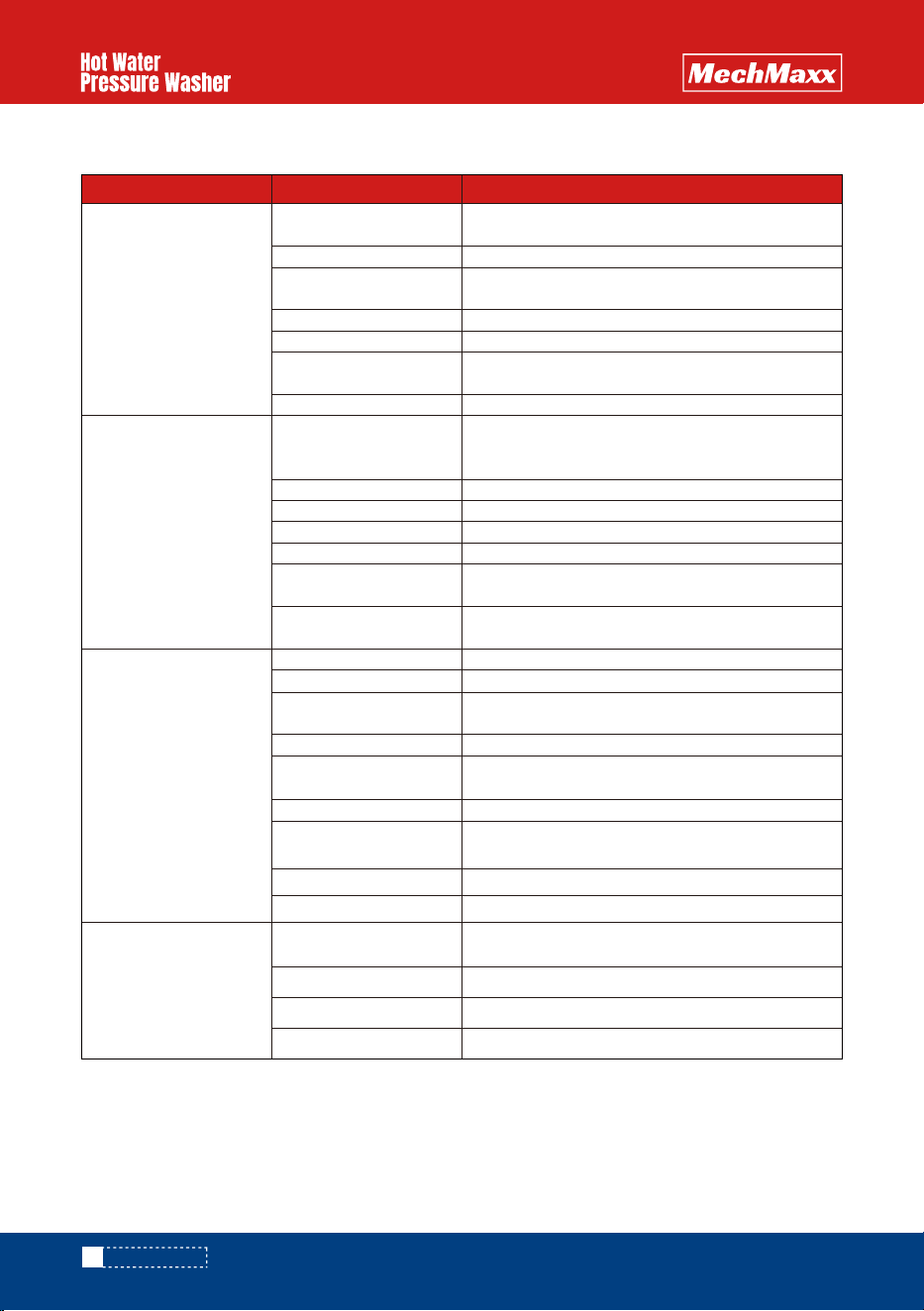
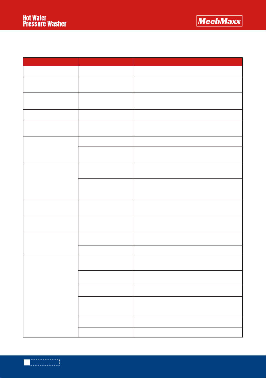
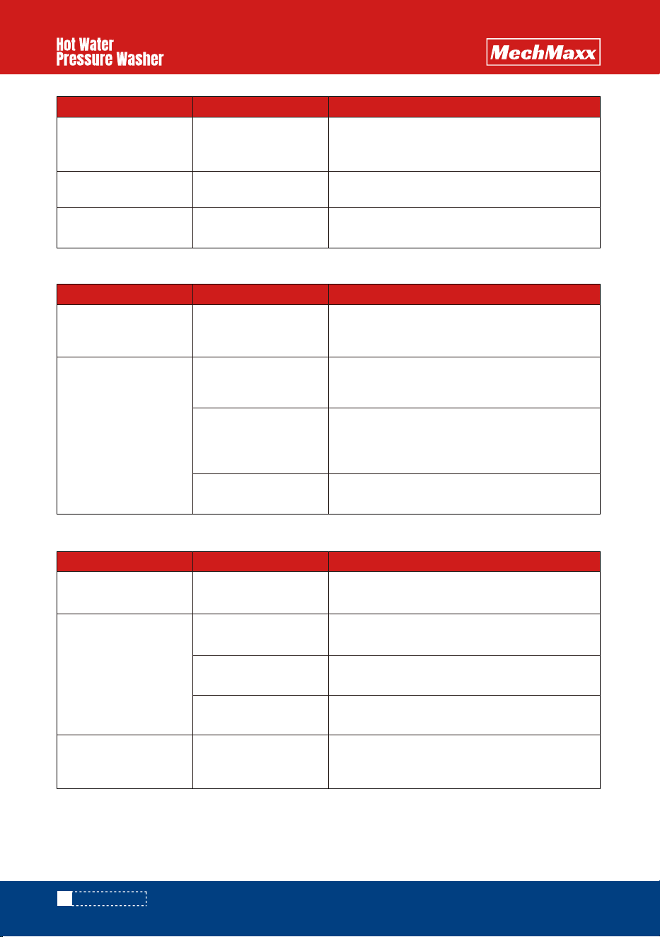
QUICK DIAGNOSTICS AND SOLUTIONS GUIDE
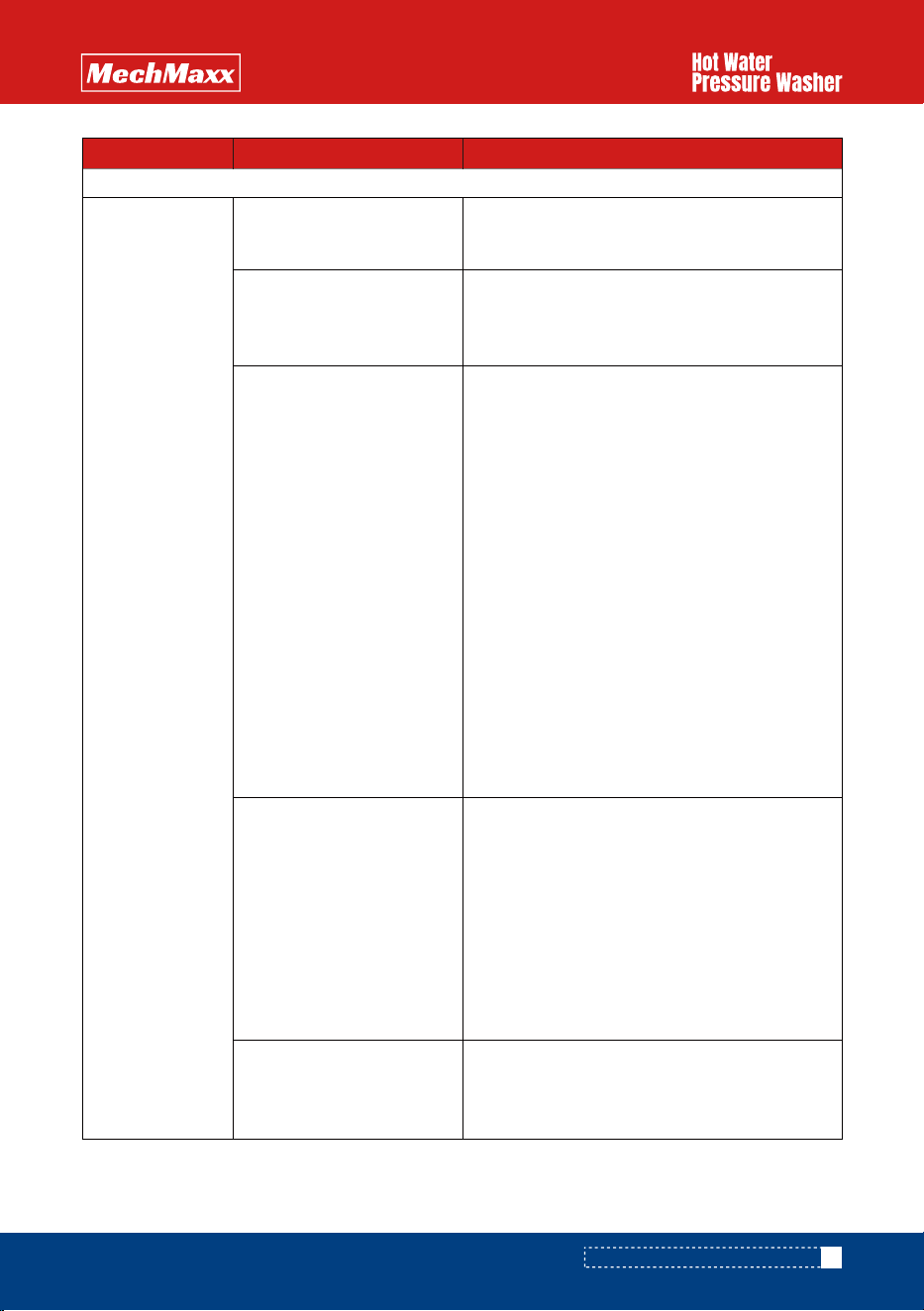
BURNER
Dead battery
Damaged thermostat
Damaged pressure switch
Damaged ignitor
Plugged filter or no fuel
No hot water
- Make sure your battery is fully charged.
- If the battery’s charge is not full, please
replace or re-charge your battery.
- Make sure thermostat is connected properly.
- If burner fan does not come on when you turn
thermostat dial, replace thermostat.
- Make sure pressure switch is connected
properly to burner unit. Take cover off
pressure switch by unscrewing the 4 screws
on the front part of the switch (switch is
located on pump). Without touching the
contacts that conduct current, push on the
little button found on the micro switch
(button is located directly above the part that
attaches directly into pump).
- If burner comes on, replace pressure
switch.
- If burner does not come on, make sure
there is current going through switch
(consult a professional for this if you do
not know how to do this properly as
you can get severely injured by the
electrical current connected to your
machine). If current properly flows
through pressure switch to burner, check
ignitor.
- Please call a repair center for help to
conduct tests on the ignitor.
- If you see vapor coming out the
top of the coil when you try to turn
the burner on while the machine is
in use, fuel is passing through the
system properlybut the ignitor is
unable to produce a spark. Replace the ignitor.
- If you don’t see vapor, check the fuel line.
SOLUTIONSPROBLEM POSSIBLE CAUSES
- Make sure you have enough fuel in the tank.
- If you have fuel, make sure the filter and fuel
line are not plugged or damaged.
www.mechmaxx.com
25
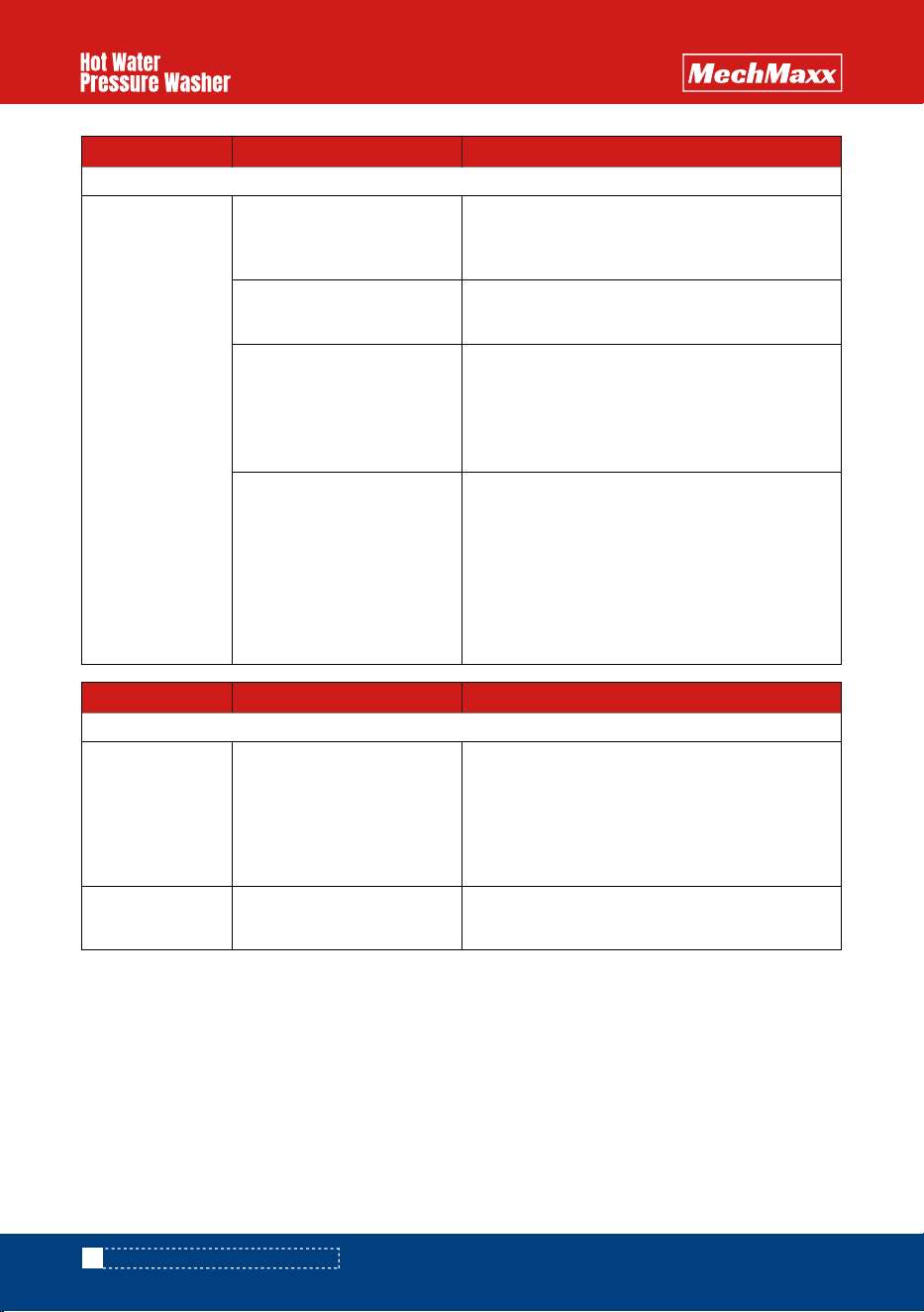
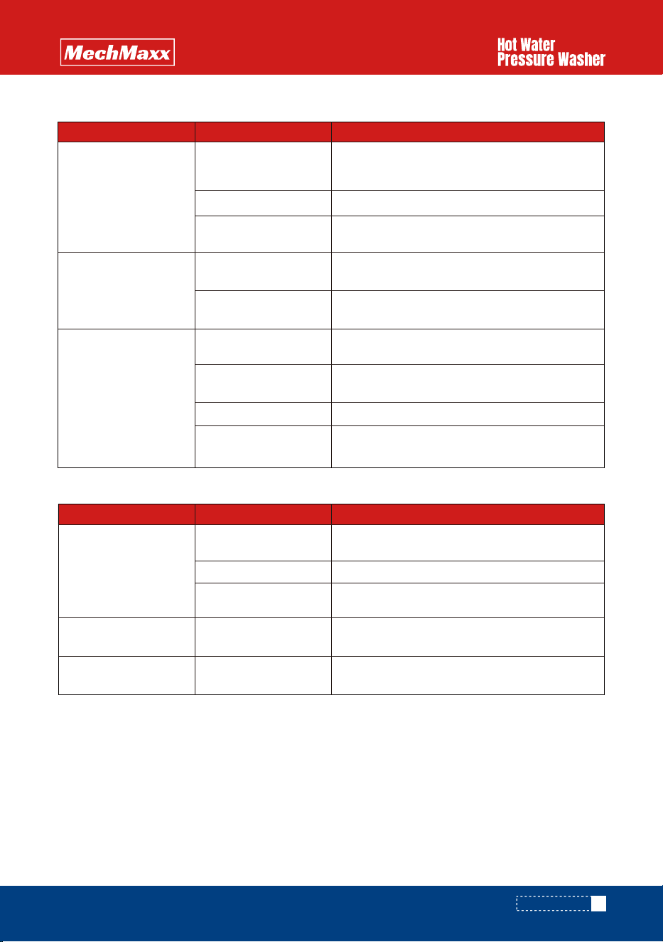
QUICK DIAGNOSTICS AND SOLUTIONS GUIDE
26
www.mechmaxx.com
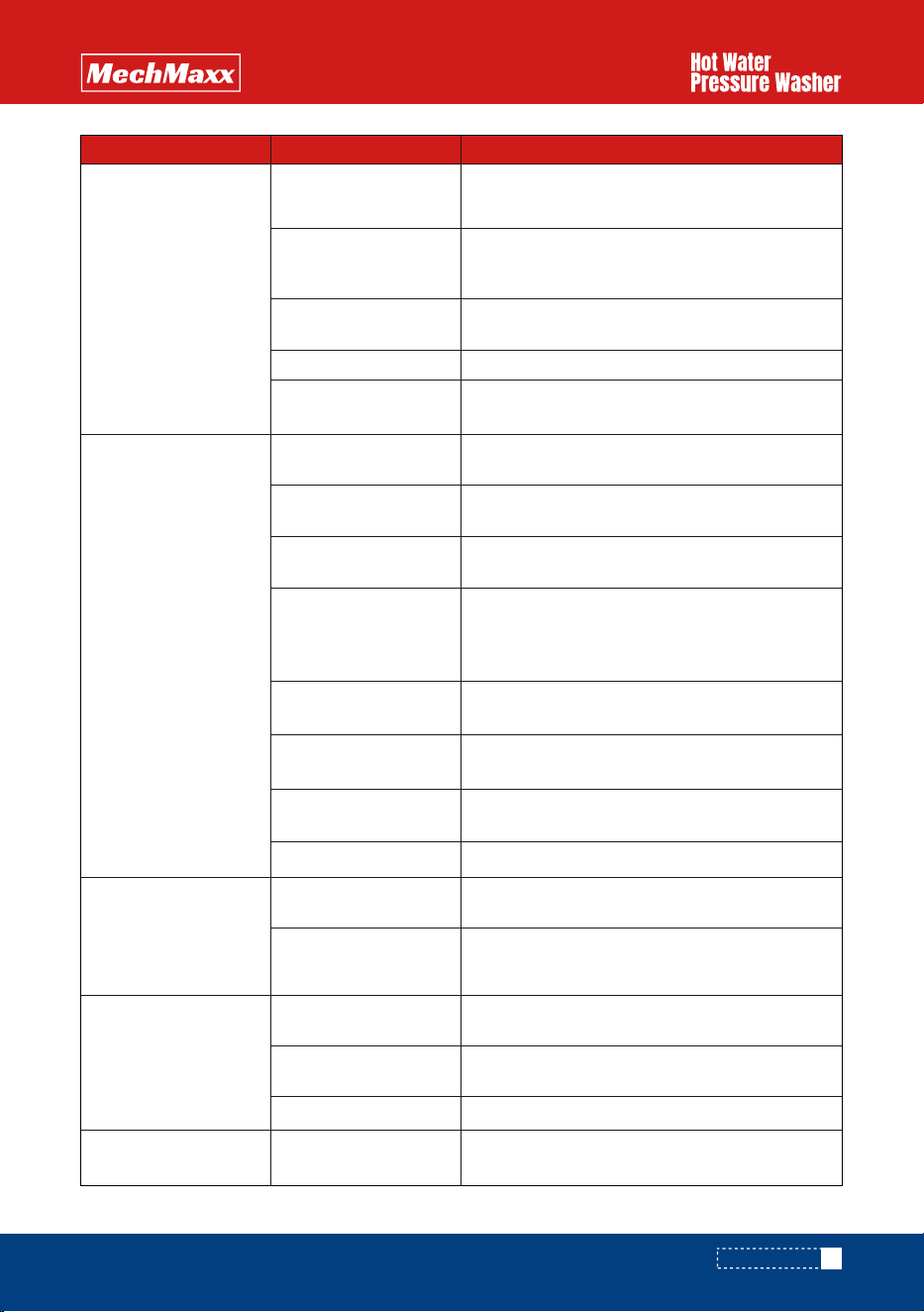
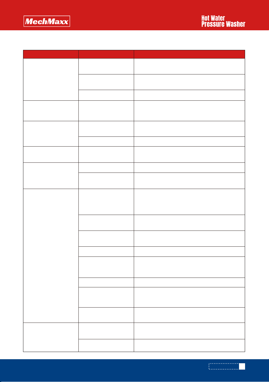
IGNITION INDICATOR LIGHT
One time
Flashing
- FUEL indicator light on
- Fuel is low,need to add fuel
- Low fuel shut-off sensor stuck or faulty
Two times
- False flame signal
- Flame detector damage (Short circuit)
SOLUTIONSPROBLEM POSSIBLE CAUSES
Three times
- Not on fire
- Electrode is not installed correctly
- Ignition transformer damage
- Flame detector damage
- Solenoid valve not energizing
Four times
- Fuel supply is insufficient
- Solenoid valve not energizing
- No fuel to bleed valve,check the fuel line
- Fuel nozzle is blocked
- Flame detector problem
- Flame detector damage
- Flame detector is covered with bituminous
coal
SMOKE
Inadequate combustionBlack Smoke
- Excessive fuel injection
- Check nozzle diameter
- Air supply is insufficient
- Check and increase engine speed
- Check the air duct to see if any air leak
- Check to see if the belt is loosed
Excessive residual fuelWhite Smoke
- Ignition failure, machine failure
- Check boiler inner wall, clean up residual fuel
SOLUTIONSPROBLEM POSSIBLE CAUSES
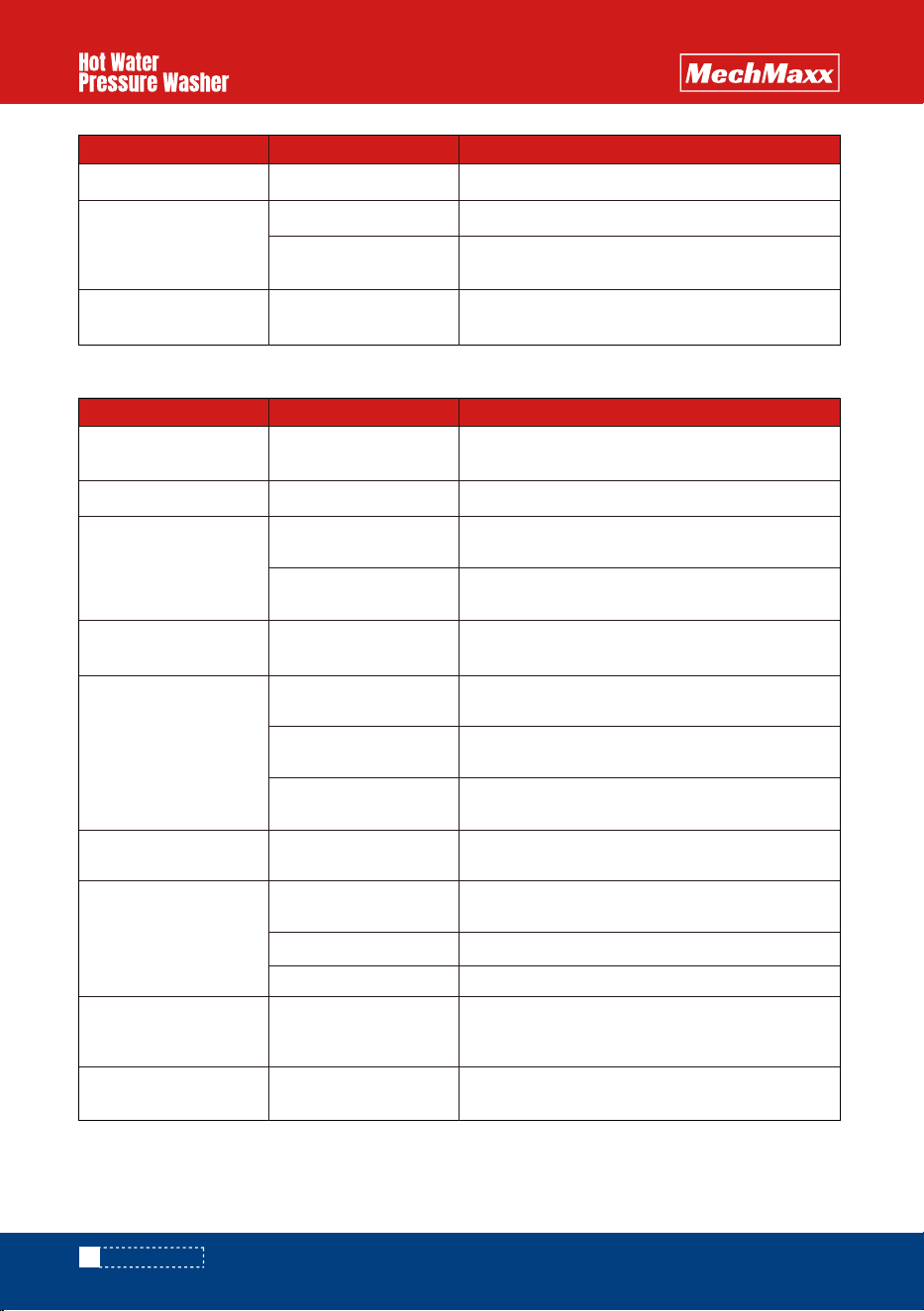
QUICK DIAGNOSTICS AND SOLUTIONS GUIDE
www.mechmaxx.com
This manual is intended for technical personnel to assist in the diagnosis and repair of issues with pressure washers.
This manual is not intended for use by non-technical personnel.
It is advised to always refer to competent technical personnel when repairs are advised to avoid equipment damage or
potential personnel injury.
SERVICE MANUAL
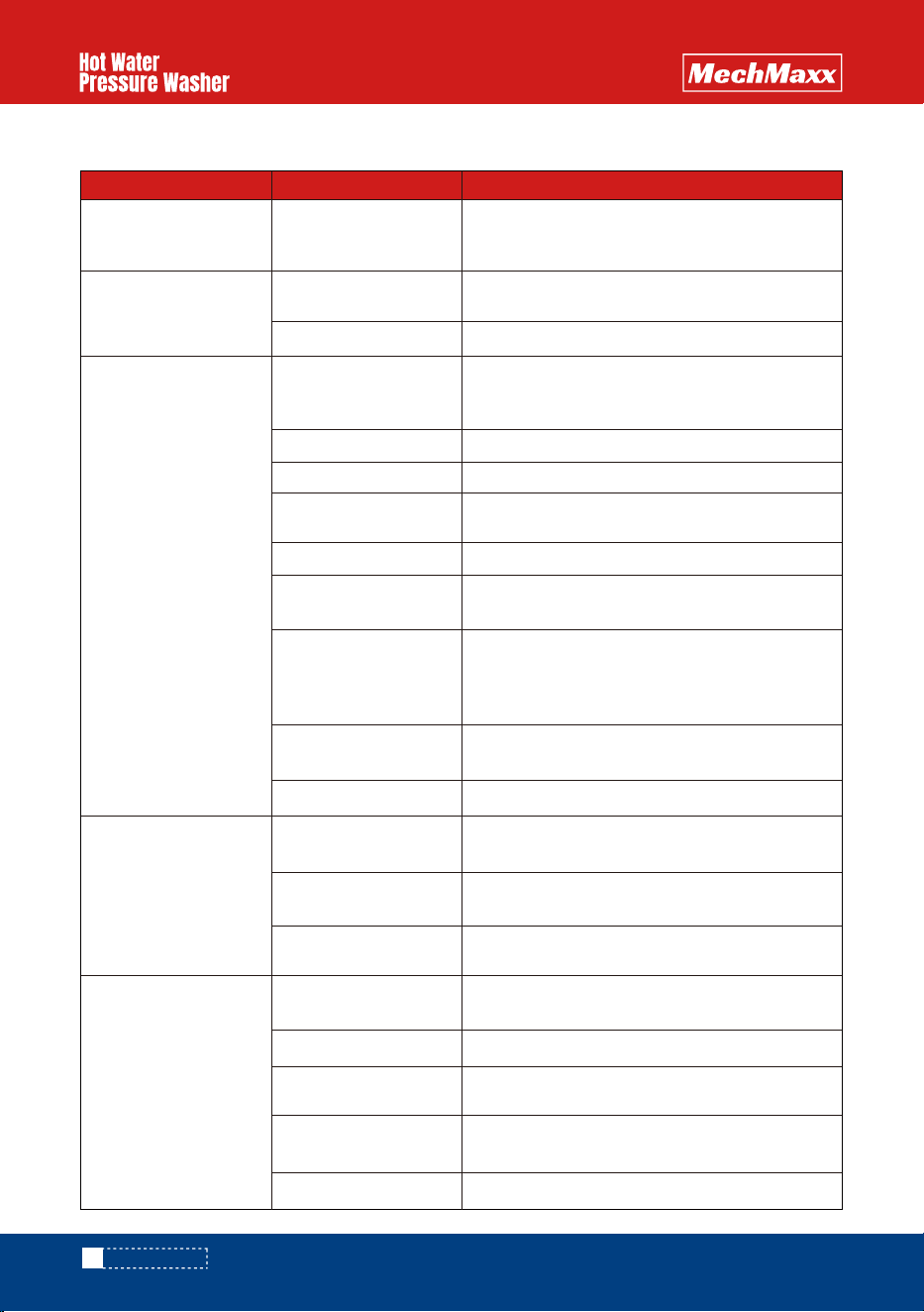
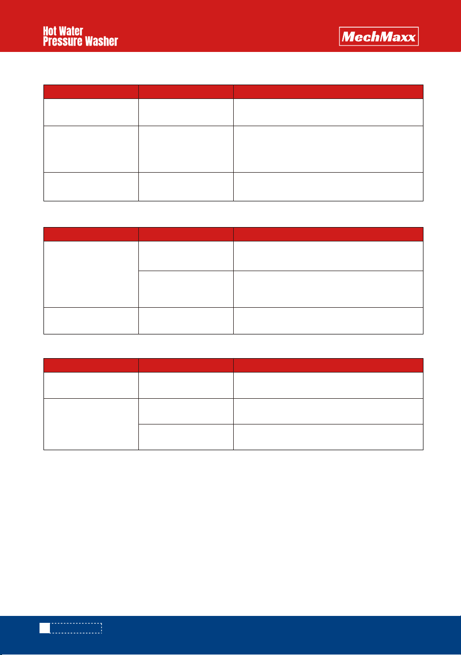
PROBLEM POSSIBLECAUSE SOLUTION
Fuel
No ignition
Electric Starter/Battery
Gas motor not starting
Plug does not fire
Bad ignitionsystem
Spark Plug - no gas smell
Poor connection
No fuel to cylinder
Fuel linerestricted
Stuck carburetor float
Bad fuel pump Replace fuel pump.
Clogged carburetor needle valve Unclog needlevalve.
Unstick float
Check fuel delivery from carburetor to cylinder. Check
carburetor float bowl for fuel.
Inspect fuel line to carburetor for restrictions or clogging
Flexible line may be kinked.
Check the source of spark for the engine ignition.
Spark Plug -
stronggas smell
Fuse blown in key switch
Flooded
No ignition
Bad plug
Poor connection
Bad magneto Check the source of spark plug for engine ignition.
Inspect the ignition connection.
Check ignition by removing spark plug from cylinder. lf
electric start, try starting using the recoil starter.
Check spark plug and replace if necessary. Carbon
deposits can indicate a fouled plug or too much fuel.
Wait 5 minutes before attempting to restart.
18 amp engine, open key switch, replace 30 amp fuse.
Recharge or replacebattery.
Check ignition by removing spark plug from cylinder. If
electric start, try starting using the recoil starter.
Check to see if proper fuel levels are maintained
27
POWER SYSTEM DIAGNOSTICS - Gas Engine Not Starting
SERVICE MANUAL
28
www.mechmaxx.com
FLUID SYSTEM DIAGNOSTICS - Flow and Pressure
PROBLEM POSSIBLE CAUSE SOLUTION
Make sure pump is operating. Check drive belts and
couplings, make necessary adjustments.
Ensure water supply is not restricted and hoses are in
good repair and not kinked.
Check spray nozzle, repair or replace.
Check inlet filter, repair or replace.
Remove and check for proper action, repair or replace.
Replace nozzle when it shows signs of internal erosion.
Clean valves and check o-rings for pits and cracks.
Adjust pressure so the water flows through properly.
Adjust unloader to proper level.
If unit has volume adjustment, it may need readjustment
Look for leaks on the discharge side of system.
If belts do not have proper deflection, replace them.
Inspect coupling and repair or replace.
Check the start or throttle-back valve for proper operation.
Ensure that the motor or engine is working properly
Piston assembly may be stuck or fouled
Distorted spray pattern can indicate a clogged nozzle.
Ensure nozzle is proper size for the system.
Correct any kinks or restrictions. Replace crushed hoses.
Defective easy start valve
(optional)
Malfunctioning motor or gear
Unloader stuck in bypass
Outlet restriction
Clogged nozzle
Nozzle too small
Hose restriction
Stripped pump drive coupling
Loose drive belts
Pump not running at rated speed
Remove the injector and retest system. If the flow is
restored, replace the injector.
Check engine throttle and see that the motor is rated for
the same speed as the pump.
Build up can restrict flow. If water is not flowing freely,
flush with garden hose to isolate the clog or restriction.
Downstream chemical injector
(Dema)
Discharge leaks
Volume Improperly adjusted
Use a new pressure gauge on a quick connect at outlet to
check system pressure and replace if gauge is faulty.
If low pressure persists, pump packings may need
replaced.
Unloader is not adjusted correctly
Lance on low pressure
Low pressure, adequate
flow
Low pressure, low flow
Low pressure, low flow
-Bogs
Pressure gauge inaccurate
Pump packings bad
Debris in valves
Worn spray nozzle
Nozzle should be properly sized for the system. Low
pressure indicates that the nozzle in use is
too large.
Faulty unloader valve
Incorrect or no spray nozzle
Float valves can become stuck in the "UP" position.
Manuallydislodge and inspect for problems.
Clogged inlet filter
Float Valve stuck (optional)
Clogged spray nozzle
No Flow
Check trigger gun, repair or replace.Trigger gun valve
No water source
No power
SERVICE MANUAL
www.mechmaxx.com
PROBLEM POSSIBLE CAUSE SOLUTION
Debris can lodge in the discharge side of the system
(valves, fittings, injectors, filters) Flushing with water may
correct it.
Nozzle must be properly sized for the rated flow and
pressure. Reset unloader or pressure relief if nozzle size
is changed.
Adjust to the proper pressure using pressure gauge.
Regularly clean the inlet and inlet strainer to keep debris
from entering the float tank
Inlet temperature should not exceed 140F - 160F range.
If there is no float tank and the outlet line does no vibrate,
the inlet check valve may be clogged. Remove debris.
Check o-rings under valves.
If there is no float tank and the outlet line does no vibrate,
the inlet check valve may be clogged. Remove debris.
If they show signs of ware or damage, replace them.
Look for the source of debris in the inlet and discharge
check valves and remove.
Inspect places where air can enter the system, i.e.; fittings,
hose, connections etc.
Water supply to hot
Air in system
Debris in inlet check valves
Debris in inlet check valves
Air in system
Pump packing bad
Inlet and outlet check
valves fouled
Inspect places where air can enter the system, i.e.; fittings,
hose, connections etc.
All inlet connections should be snug and not kinked to reduce
the chances of pump starvation.
Water supply to the system must meet or exceed the rated
flow (GPM) on the serial number plate. Faucet must be
completely opened or water above the tank outlet in a gravity
fed system.
If float valve is stuck in the up position, water can not enter
the float tank. Unstick valve if possible of replace if necessary.
Excessive turbulence allows the pump to draw air into the
system. Correct excessive turbulence.
Air in system
Chemical line not submerged
Pump chatters, caviataion,
vibration
Inlet line vibrates
Outlet line vibrates
Inlet and outlet lines
vibrate
Inlet line restricted
Inadequate water supply
Float valve stuck (optional)
Turbulence in float tank
(optional)
Inlet or inlet strainer clogged
Improperly adjusted unloader
Check the pressure gauge using a properly calibrated
pressure gauge on quick connects at the equipment outlet.
Check the unloader action. If it is not working properly,
it may need repaired or replaced.
Inspect places where air can enter the system. i.e. fittings,
hose, connections etc.
If the chemical valve is on, ensure that the chemical line is
fully submerged in the chemical
Faulty pressure gauge
Faulty unloader
Excessive pressure
Debris in the system
Small spray nozzle
29
SERVICE MANUAL
30
www.mechmaxx.com
FLUID SYSTEM DIAGNOSTICS -Unloader
PROBLEM POSSIBLE CAUSE SOLUTION
Isolate the flow problem. If it occurs before the unloader
discharge point, check the piston assembly to see if it is
fouled or stuck in bypass mode.
Take bottom nut off unloader, identify ball, spring and
seat. Clean out any debris and
Check for leaks and repair.
A nozzle that is too small can cause the flow to be reduced.
A distorted spray pattern indicates a clogged nozzle.
Check inlet water supply for excessive pressure.
Remove the accumulator from the system.
A distorted spray pattern indicates a clogged nozzle.
A small nozzle causes a reduced flow and cycling may
result.
If the system has a Venturi injector downstream of the
unloader, check the orifice for clogs.
See flowdiagnostics.
High water supply pressure
No restrictions on the
unloader
Unloader adjusted too low
Spray nozzle clogged
Spray nozzle too small
Injector orifice blocked
System not delivering rated flow
Downstream leakage
(excessive)
Accumulator downstream
(option)
Check unloader bypass port to see if a flow restrictor is
properly installed. Install one if none is present.
Causes the unloader to since a continuing flow and divert
it to the closed gun. Repair or replace.
Adjust the unloader using the pressure gauge for the
correct pressure.
Nozzle clogged
Improper unloader orifice
Unloader orifice clogged
Injector orifice clogged
Other downstream restriction
Pump not delivering the rated
pressure
Unloader (flow) cycles
with system under
pressure
Unloader (flow) cycles
with system in bypass
Unloader (pressure)
produces smooth flow &
low volume
Any variation in flow form what the orifice is sized can
cause cycling. System must produce the rated
flowconstantly.
The systems rated output should indicate the proper
sized orifice for your system.
If the system has a Venturi injector downstream of the
unloader, check the orifice for clogs.
Scale buildup can restrict flow. Check; controls, valves,
switches, trigger gun, and lance. Descale as necessary
and begin preventive maintenance program for scale
prevention.
Check the orifice for clogs and clear out any debris.
See low pressure or low flow diagnostics.
Improper flow
Nozzle to small
Very low or no flow
Unloader will not unload
Unloader stuck in bypass
Debris in unloader
Sever leak on the outlet of unit
SERVICE MANUAL
www.mechmaxx.com
31
PROBLEM POSSIBLE CAUSE SOLUTION
Adjust unloader and regulator until proper pressure is
achieved.
If unloader is sticking, repair or replace as necessary.
If the unloader is diverting flow to bypass it may be
adjusted too low, readjust as necessary.
Ensure the proper nozzle is installed on system.
Check unloader shaft for proper action. Unstick piston and
shaft or replace unloader.
Unloader piston stuck or
frozen
Bypass port clogged or
restricted
Sleeve O-ringworn
Excessive tension on main
spring
Ensure that unloader bypass port is not clogged
If tension is incorrect, adjust or replace as necessary.
Check O-rings for ware or damage and replace as
necessary.
Spray nozzle tolarge
Internal nozzle erosion
Insufficient pump pressure
Unloader adjusted too low
Nozzle too large
Shaft O-ring in valve body
warn
Unloader (pressure)
produces low
flowand normal
pressure
Unloader (flow) produces
low flow & normal
pressure
Unloader (pressure) leaks
from main spring or
adjusting bolt
Unloader (flow) pressure
increases when trigger
released
Unloader (flow) leaks
water around adjusting
bolt
Downstream restrictions can cause a reduction in flow.
Check; controls, valves, switches, trigger gun, and lance.
Descale as necessary and begin preventive maintenance
program for scale prevention.
The number of hours of usage can give you a clue to the
extent of the ware. If in doubt, change
If unloader is diverting flow to bypass, readjust using the
pressure gauge.
Ensure the proper sized nozzle is being used.
Check pump seals and packings and tighten drive belts.
Check O-rings for ware or damage and replace as
necessary.
Unloader adjusted too low
Unloader (flow) produces
smooth flow & lowvolume
Unloader adjusted too low
Unloader valve stuck inbypass
Restriction in system
SERVICE MANUAL
FLUID SYSTEM DIAGNOSTICS- Leaking ANY LEAKS SHOULD BE REPAIRED ASAP TO
PREVENT DAMAGE TOTHE SYSTEM.
PROBLEM POSSIBLE CAUSE SOLUTION
Ensure the washer is present and in good condition.
Low pressure line should be properly sealed on barb and
tightly clamped.
If float is not floating above water, check the float to see if
it has filled up with water. If necessary, drain and seal.
If the seal leak is detected under the pump manifold,
packing may be worn and in need of replacement.
If o-rings show wear or damage, they may need replaced.
Physical damage may not be apparent, but unseen warping
from freezing or extreme pressure can still cause leakage.
If a weep gun has been installed, check the gun valve seat
to ensure it is functioning properly.
Inspect trigger gun valve assembly for damage or ware to
ball or seat. Lodged debris can stop valve from closing.
Repair with kit or replace.
If quick connect o-ring shows wear, damage or improper
seating.
Take bottom nut off unloader, identify ball, spring and seat.
Clean out any debris and reassemble.
Check for leaks and repair.
Inspect o-rings for ware or damage and replace as
necessary.
See pressure and flow diagnostics to find the cause of the
excessive pressure and correct it.
If water spurts from valve when trigger is released, check
unloader adjustment. Pressure spike should be below the
level where pressure relief valve is activated.
Inspect ball and seal for damage and adjust as necessary.
Adjust valve properly.
If trigger gun valve action is not correct, repair or replace.
Clogged nozzle
Trigger gun valve not working
Excessive pressure spike
Wear or damage to ball or seal
Improper relief valve adjustment
System over pressure
Spray pattern will be distorted if nozzle is clogged, clean
out.
From pump
From trigger gun
From nozzle
From unloader
From variable pressure
Lance(option)
Unloader will not unload
From pressure relief valve
If quick connect o-ring shows wear or damage, replace it.Bad o-rings
Bad packing
Bad rod o-ring
Weep gun (optional)
Damage gun valve ball or seat
Bad o-rings oe selas
Bad o-rings at adjusting knob
Debris in unloader
Sever leak on the outlet of unit
Stripped connectors
From inlet
From low pressure (inlet)
line fittings
From float tank(option)
From quick connects
Garden hose washer
Loose clamps or connections
Float tank full of water or
stuck
32
www.mechmaxx.com
SERVICE MANUAL
www.mechmaxx.com
33
FLUID SYSTEM DIAGNOSTICS - Trigger Gun/Spray Nozzle
PROBLEM POSSIBLE CAUSE SOLUTION
If water flows through discharge hose without gun, check
trigger gun valve piston rod and replace if necessary.
Inspect to assure insert is in place.
Check nozzle or spray accessory for blockage and clear it.
After unloader increases pressure to a maximum, further
adjustment will only increase the pressure spikes.
Re-adjust.
If trigger action is too loose, return spring may need
replaced.
Debris in gun valve can stop piston return. Clear debris.
It may be possible to loosen plug slightly without leakage
but it will likely need replaced.
Check trigger gun o-rings for ware or damage and replace.
Physical damage may not be apparent but unseen warping
from freezing or sever overpressure maystill cause leaking.
Open chemical valve. If It chatters with no chemical
delivery, air is being drawn from the upstream side of the
pump. Check fittings, connections and ensure the inlet line
is fully submerged into the chemicaljug.
May be a strainer or check valve. Ensure that the ball is not
stuck or clogged.
An overly long chemical line can prevent the pump from
drawing chemical into the system. Try installing a shorter
line.
Downstream injectors only - Low pressure is required for
most injectors to draw chemical. If no adjuster exists it
may need low pressure spray nozzle installed on the lance.
If not properly sized for the systems rated output, chemical
delivery problems will result. Check serial plate for specs.
To properly adjust, a chemical flow meter may be used to
precisely measure chemical flow.
Verify chemicalstrength.
Inspect and clean as necessary.
Chemical line kinking or binding prevents chemical delivery.
Verify chemicalstrength.
Excess pressurewhen
trigger gun isreleased
Flow not stopping when
trigger gun released
Trigger action sticks
Trigger gun leaks
No chemical
Excessive chemical
Excessive pressure spikes
Keeper plug too tight
Worn or bad o-ring
Stripped or loose connections
Chemical valve closed
Black nozzle
Chemical dried up in the
injector
Chemical foot strainer
clogged
Chemical line kinked
Chemical line too long
Chemical too dilute
No adjustment for low
pressure
Incorrect injector orifice
Valve improperly adjusted,
check knob on injector
Chemical dilutionto strong
Broken return spring on
trigger gun
Debris in gun valve
No nozzle flow from
nozzle when trigger
depressed.
Broken piston rod in trigger
gun
Missing metal insert in trigger
gun (European style gun)
Blockage in system past gun
SERVICE MANUAL
BOILER SYSTEM DIAGNOSTICS - Oil Burner Will Not Fire
PROBLEM POSSIBLE CAUSE SOLUTION
Spray pattern will be distorted if nozzle is clogged.
A loss of pressure may result form gradual nozzle wear.
Replace a nozzle of correct size.
Ensure that the nozzle is sized properly sized for the system
Spray pattern will be distorted if nozzle is clogged. Check
nozzle for clogging if the unit has a pressure unloader.
Volume proper, pressure
low
Pressure proper, volume
low
Clogged nozzle
Spray pattern irregular Clogged nozzle
Nozzle to large
Internal nozzle wear
PROBLEM POSSIBLE CAUSE SOLUTION
Correct the fluid problem first - See fluid systems
diagnostics
Set thermostat to an output temperature requiring heating.
Check fuel and bring to proper levels. Inspect fuel tank for
water or debris.
Ensure that the blower is working and that the air band or
damper is properly adjusted and in good repair.
Ensure that the proper clean fuel is being used. If not,
siphon any debris or water from the tank.
If the improper fuel is found in the tank, drain and rinse the
tank, then fill with proper fuel.
Check the sensor. The assembly may need to be removed
to un-stick the float or to replace it completely.
Drain water from the tank promptly to prevent rusting. If
fuel delivery problems persist, check the fuel pump for rust.
Check only if no fuel in the filter bowl - Drain the tank and
check for rust. If problem persists, fuel pump should be
checked forrust.
Check fuel delivery and correct any problems.
If the fuel strainer or in-line filter is clogged, clean or
replace.
Replace if there is any evidence of clogging or debris.
Check lines for clogging and clear if necessary.
Full featured equipment may have a shut off if fuel is low.
Thermostat on low setting
No or low fuel in tank
No air movement through
stack
Fuel in the fuel tank
Water in the fuel filter bowl
Debris in the fuel filter
bowl
Water comes out drain at
bottom of tank
Cannot smell or see fuelat
stack
Burner no getting adequate
fuel
Low fuel shut-off control
activated.
No air being supplied
Contaminated fuelin the tank
Improper fuel in the tank
Low fuel shut-off sensor
stuck or faulty
Water in fuel supply
Clogged strainer
Clogged fuel nozzle
Clogged fuel line
Water in fuel supply
No fuel being supplied
Not reaching rated
pressure flow
Not activating boiler controls
Thermostat set too low
34
www.mechmaxx.com
SERVICE MANUAL
PROBLEM POSSIBLE CAUSE SOLUTION
Ensure that air is not entering through the lines or
connections.
Ensure that the fuel line is connected and is not
broken/punctured.
Check any clogging that exists in the fuel filter
Check any clogging that exists in the fuel inlet line.
If the fuel pump is frozen it will need replaced.
Check pump coupling if direct or belt driven. Replace or
tighten or replace the drive belts if needed.
Remove the solenoid cover and place blade of an insulated
screwdriver in the coil with the system operating in hot
water mode. A good working solenoid will hold the
screwdriver in the solenoid. If not it may need replaced.
If boiler controls work properly, the pressure or vacuum on
the fuel pump may be misadjusted. Check solenoid coil
again.
Check for clogging in the solenoid valve inside fuel pump.
Check fuel nozzle for clogging and clear if necessary.
Check fuel line from pump to burner for any restriction.
Check piston in fuel pump to see if it will travel. Free piston
or replace fuel pump.
Ensure the proper voltage is reaching the ignition
transformer with a volt meter.
Using a volt meter, ensure that the transformer is supplying
the proper voltage.
Check the gap and readjust if necessary, taking care that
the proper distance is maintained from the fuel nozzle.
Down fired, multi-pass boiler systems have a cap on the top
of each electrode. Examine caps for cracks or carbon
build- up and replace if there problems are evident.
Applies to down fired, multi-pass boiler systems - Check the
wire to each electrode to ensure there is a good connection.
Electrodes should not be arcing to fuel lines or nozzle.
Check electrode for cracking or carbon build-up.
Applies to gun type burners - Bus bars on the transformer
should line up and connect properly with the
electrodeterminals
Oil pump may have debris, replace as necessary.
Steady fuel flow at bleed
valve but none in
combustion chamber
Boiler controls activating
Solenoid valve energizing
Air and fuel flow proper
Solenoid valve coil not
energizing
Debris in internal fuel pump
valve
Fuel nozzle clogged
Restriction in fuel outlet line
Fuel pump piston frozen
closed
No power reaching
transformer
Ignition transformer bad
Electrode gap improperly set
Electrode caps cracked
Electrode wires loose or
damaged
Electrodes arcing to fuel lines
Transformer bus bars not
lining up
No fuel to bleed valve
Air leak to pump
Broken fuel line
Clogged fuel filter
Clogged fuel inlet line
Frozen fuel pump
Broken fuel pump coupling
Solenoid valve not energizing
www.mechmaxx.com
35
SERVICE MANUAL
BOILER SYSTEM DIAGNOSTICS Water Output Temperature Too Low
BOILER SYSTEM DIAGNOSTICS - Boiler Controls
PROBLEM POSSIBLE CAUSE SOLUTION
Check air delivery to combustion chamber. Down fired;
check air damper and air bag. Gun type; Check air bands.
Ensure electrode gap is properly set.
Open air bands to proper setting.
Excessive electrode gap
Choked down
Burner or electrode
assembly fires when
removed from housing
Ignites with air bands
closed down
Ignites with airbands
opened up
Improper air delivery
PROBLEM POSSIBLE CAUSE SOLUTION
Set the thermostat to proper output temperature.
If inlet water is freezing to the touch, the boiler may not be
able to reach desired temperature increase. Use a water
supply with a higher temperature.
Soot build up on the coil can keep the water from reaching
the desired If inlet water is freezing to the touch, the boiler
may not be able to reach the desired temperature increase.
Use a water supply
The outlet fitting to the hose can get scale build-up and
reduce heat exchange. Descale and prevent further build-up.
Inlet water too cold
Sooting
Scaling
Burner firing normally but
with outlet temp lower
than rated
Burner firing constantly
Thermostat set too low
PROBLEM POSSIBLE CAUSE SOLUTION
A multimeter can be used to check continuity through
controls and pinpoint the problem areas.
Electrical connections to solenoid valve coil should be tight
and not corroded.
Check to see if fuel solenoid will energize when the proper
voltage is applied. Solenoid may need replacing.
If solenoid valve coil energizes when the cleaner is
operating in hot water the problem is elsewhere. Check
the air/fuel delivery.
If coil energizes when proper voltage is applied, check boiler
controls.
Bad connection to solenoid
coil
Coil bad
Boiler control not activating
properly
Problem occurring elsewhere
No voltage solenoid
Solenoid coil doesnot
energize
Solenoid coil energizes
Boiler control or electrical
problem
36
www.mechmaxx.com
SERVICE MANUAL
PROBLEM POSSIBLE CAUSE SOLUTION
Replace switch if improper diaphragm movement is
detected.
Correct problems related to inadequate water flow.
Replace vacuum switch if diaphragm shows an air leak or
hole.
If vacuum switch works properly, continue with other boiler
control diagnostics.
Replace switch with another one.
Switch activated manually
Switch shows continuity
when activated
Switch does not shows
continuity when activated
Improper diaphragm
movement
Low water flow
Air leak in or punctured
diaphragm
Problem elsewhere insystem
Switch contact bad
BOILER SYSTEM DIAGNOSTICS - Pressure Switch
BOILER SYSTEM DIAGNOSTICS - Vacuum Switch - Optional
PROBLEM POSSIBLE CAUSE SOLUTION
A multimeter can indicate if the proper voltage flows
through the boiler side of the switch. If not the switch may
not need replaced.
Switch may be improperly wired for its function.
If wiring is proper and still no current flow when activated,
switch may need replacement.
Check to see if the plunger is traveling far enough to
depress the microswitch. Adjust if necessary.
If switch activates manually but boiler does not fire, current
may not be flowing through. The switch may need replacing.
Microswitch may need readjustment so plunger can trip in.
Replace switch with another one.
If switch works manually and current is flowing properly, the
problem is elsewhere. Try other boiler diagnostics.
Check pressure plunger to see if it will travel freely. If not,
the passage may need cleared.
Switch improperly wired
Switch bad
Plunger fouled or stuck
Plunger not moving far
enough
Current not flowing through
switch
Microswitch not properly
adjusted
Switch bad
Problem elsewhere in the
system.
Switch activates when
pressure is reached but
boiler not firing
Switch does not activate
Switch activated manually
Control not flowing through
switch
www.mechmaxx.com
37
SERVICE MANUAL
BOILER SYSTEM DIAGNOSTICS - Thermostat
BOILER SYSTEM DIAGNOSTICS - High Temperature Limit
BOILER SYSTEM DIAGNOSTICS - Low Fuel Shut-Off
PROBLEM POSSIBLE CAUSE SOLUTION
Set thermostat properly and ensure connections are not
loose or corroded.
Replace Thermostat.
Continue with boiler control diagnostics. If boiler still does
not fire, the thermostat may need replaced.
Thermostat bad
Problem elsewhere insystem
Thermostat set improperly
Boiler fires when
thermostat jumped, but
will not fire with
thermostat in circuit
Boiler will not fire when
thermostat jumped
Thermostat set too low
PROBLEM POSSIBLE CAUSE SOLUTION
Check connections to high temperature limit switch to ensure
that they are not loose or corroded.
If there is continuity through the switch but the boiler still
does not fire, there is a problem elsewhere in the system.
Continue with boiler control diagnostics.
Replace switch.
Problem elsewhere in system
Switch bad
Electrical continuity
through switch
No continuity through
switch
Connections loose or
corroded
PROBLEM POSSIBLE CAUSE SOLUTION
Add fuel and retest.
Check level sensor for proper movement. Clear, repair, or
replace sensor assembly.
Check level sensor for proper action. Replace switch if
needed.
Level sensor stuck
Reed switch bad
Fuel level low
Fuel level proper
Switch may be operating
properly
38
www.mechmaxx.com
SERVICE MANUAL
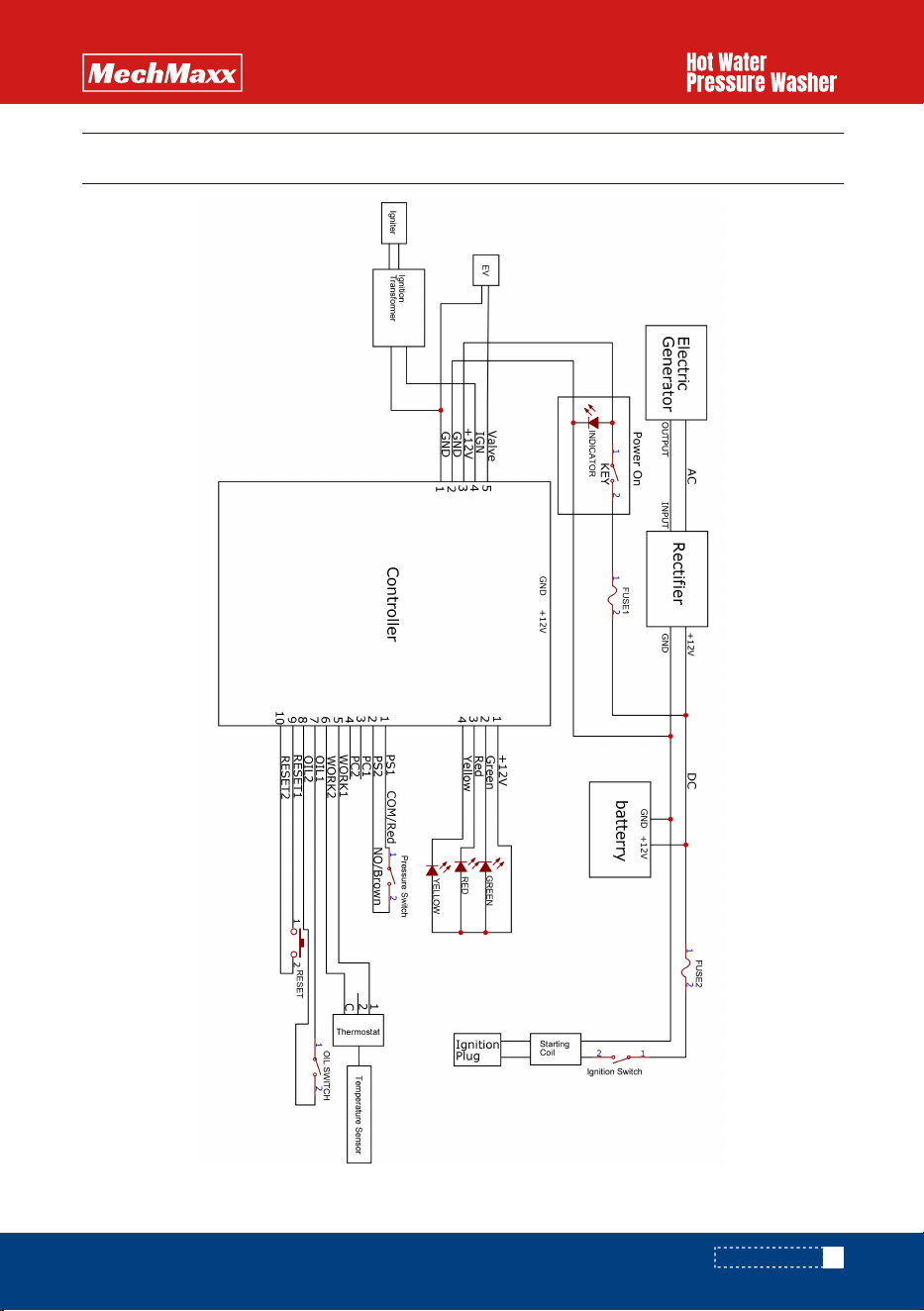
WIRING DIAGRAMS
Model: HPW40H, HPW40K, HPW40D
www.mechmaxx.com
39
WIRING DIAGRAMS
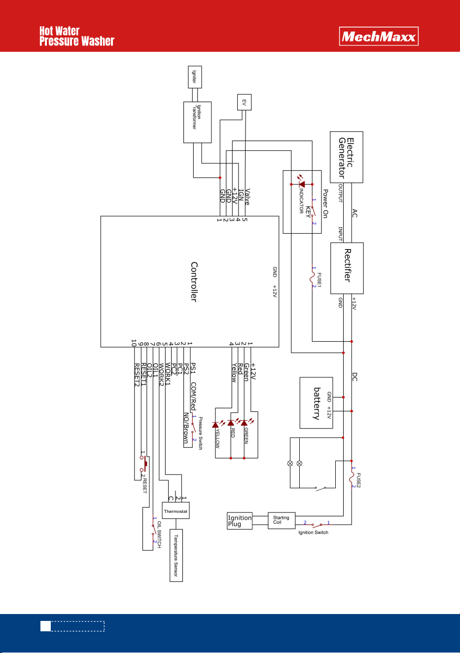
Model: HPW40HT, HPW40HBT, HPW40DT, HPW40DBT, HPW40KT, HPW40KBT
40
www.mechmaxx.com
WIRING DIAGRAMS
2 1
LED Work Light
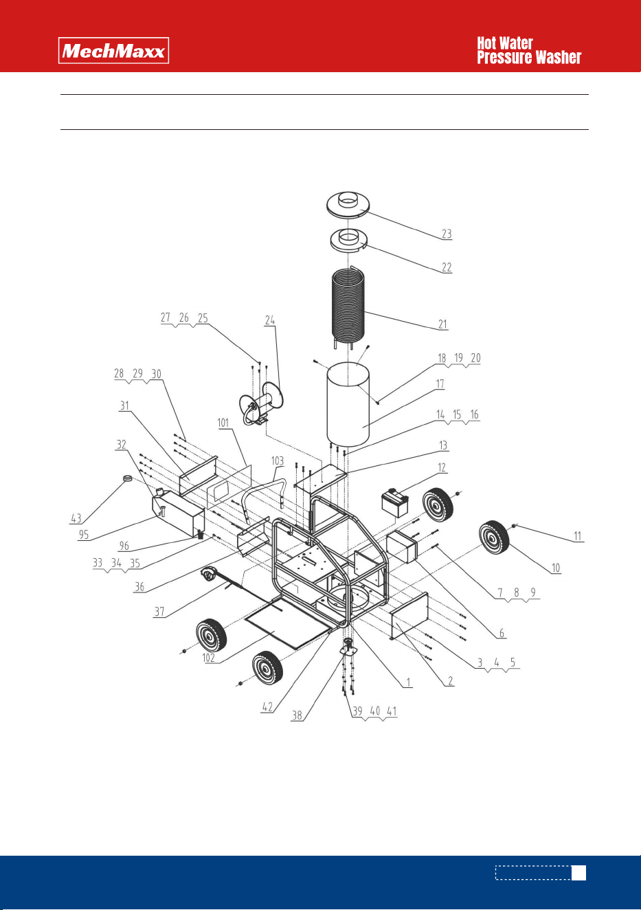
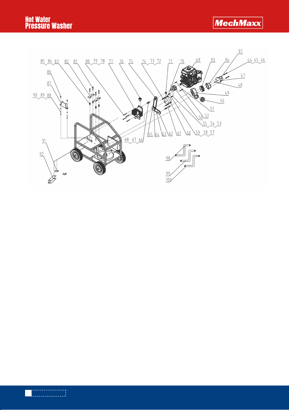
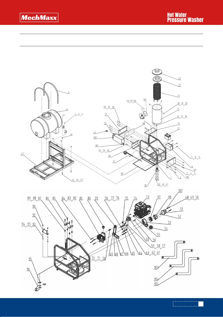
PARTS DIAGRAMS
HPW40H / HPW40K / HPW40D
www.mechmaxx.com
41
PARTS DIAGRAMS
42
www.mechmaxx.com
PARTS DIAGRAMS
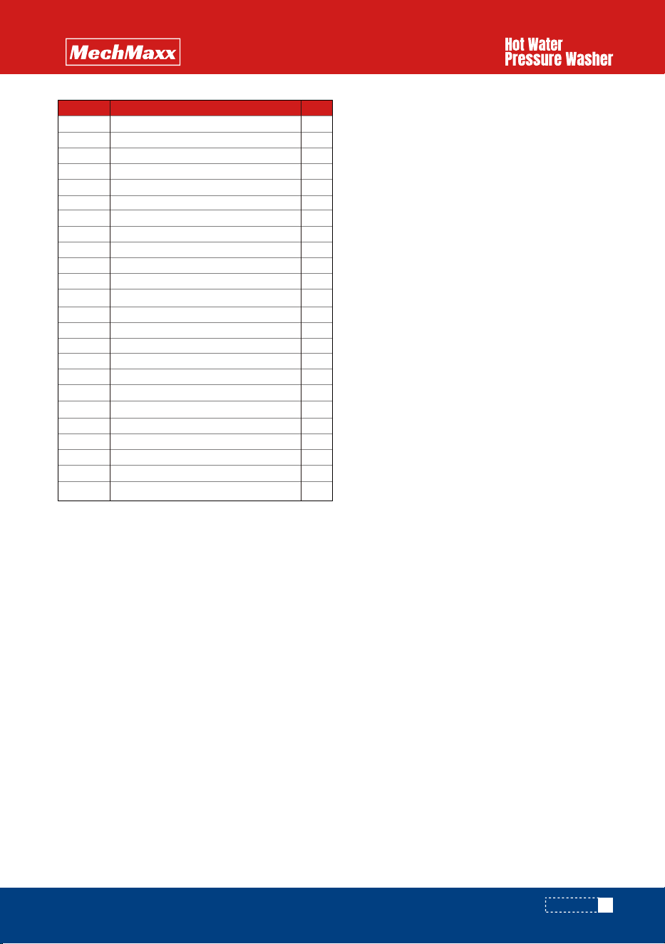
Qty.
1
2
3
4
5
6
7
8
9
10
11
12
13
14
15
16
17
18
19
20
21
22
23
24
25
26
27
28
29
Main frame
Right panel
Washer M6
Spring washer
Screw M6*20
Control box
Washer M6
Spring washer
Screw M6*30
Wheel 13"
shock pad of the wheel
Battery 12V
Cover panel
Washer M6
Spring washer
Screw M6*20
Heater cover
Washer M6
Spring washer
Screw M6*20
Heater coil
Heater inside cover
Heater outside cover
Hose reel
Washer M6
Spring washer
Screw M6*20
Washer M6
Spring washer
Screw M6*20
Left panel
Diesel tank
Washer M6
Spring washer
Screw M6*30
Bottom panel
High pressure gun
Ignition disc/ Frame detector
Washer M8
Spring washer
Screw M8*35
Wheel axis
Cover of diesel tank
Screw M8*35
1
1
6
6
6
1
4
4
4
4
4
1
1
6
6
6
1
3
3
3
1
1
1
1
4
4
4
6
6
6
1
1
4
4
4
1
1
1
4
4
4
2
1
4
4
4
1
1
1
1
1
1
4
4
4
1
2
2
2
2
1
1
1
1
1
1
1
1
1
2
1
1
2
2
1
1
1
4
4
4
4
4
4
4
4
2
1
1
Washer M8
Spring washer
Oil pump
Connect rod
Fan's cover
Bellows
Screw M10*70
Screw M10*35
Screw M8*35
Washer M8
Spring washer
Cast iron
Washer M8
Spring washer
Nut M8
Bearing
Axis
Pulley 1
Belt 1
Pulley 2
Belt 2
Washer M10
Spring washer
Nut M10
Gasoline engine
Screw M8*35
Alternator
Washer M8
Spring washer
Nut M8
Pulley 3
Pressure gauge
Pressure pump
Screw M8*35
Washer
Spring washer
Screw M10*40
Shock absorber
Screw M10*20
Spring washer
Nut M10
Screw M8*25
Belt's cover
Washer M8
30
31
32
33
34
35
36
37
38
39
40
41
42
43
44
81
82
83
84
85
86
87
88
DescriptionPart # Qty.DescriptionPart #
79
80
48
45
46
47
49
50
51
52
53
54
55
56
57
58
59
60
61
62
63
64
65
66
67
68
69
70
71
72
73
74
75
76
77
78
PARTS LIST
www.mechmaxx.com
43
PARTS LIST
Qty.
89
90
91
92
93
94
95
96
97
98
99
100
101
102
103
Spring washer
Nut M8
Shock absorber
Holder
Fan wheel
Fan cover
liquid level switch
Diesel filter cup
Solenoid valve
pressure hose 50cm
pressure hose 70cm
pressure hose 15m
plate
Shield
Handle
2
2
2
2
2
1
1
1
1
1
1
1
1
1
1
DescriptionPart #
PARTS LIST
44
www.mechmaxx.com
PARTS DIAGRAMS
HPW40HT, HPW40HBT, HPW40KT, HPW40KBT, HPW40DT, HPW40DBT
www.mechmaxx.com
45
PARTS DIAGRAMS
PARTS LIST
46
www.mechmaxx.com
Qty.
1
2
3
4
5
6
7
8
9
10
11
12
13
14
15
16
17
18
19
20
21
22
23
24
25
26
27
28
29
Main frame
Right panel
Washer M6
Spring washer
Screw M6*20
Control box
Washer M6
Spring washer
Screw M6*30
Water tank
Rachet tie down
Battery 12V
Cover panel
Washer M6
Spring washer
Screw M6*20
Heater cover
Washer M6
Spring washer
Screw M6*20
Heater coil
Heater inside cover
Heater outside cover
LED work light
Washer M6
Spring washer
Screw M6*20
Washer M6
Spring washer
Screw M6*20
Left panel
Diesel tank
Washer M6
Spring washer
Screw M6*30
Bottom panel
High pressure gun
Ignition disc/ Frame detector
Washer M8
Spring washer
Screw M8*35
Base welder
Cover of diesel tank
Screw M12*45
1
1
6
6
6
1
4
4
4
1
2
1
1
6
6
6
4
3
3
3
1
1
1
2
4
4
4
6
6
6
1
1
4
4
4
1
1
1
4
4
4
2
1
4
4
4
4
4
4
4
4
1
1
1
1
1
1
2
2
2
2
1
1
1
1
1
1
1
1
1
1
1
1
2
1
2
2
2
1
1
1
4
4
4
4
4
4
4
Washer M12
Spring washer
Nuts M12
Screw M8*35
Washer
Spring washer
Oil pump
Connect rod
Fan's cover
Bellows
Screw M10*35
Screw M10*70
Screw M8*35
Washer M10
Spring washer
Cast iron
Washer
Spring washer
Nut M8
Bearing
Axis
Pulley 1
Belt 1
Pulley 2
Belt 2
Washer
Spring washer
Nut
Gasoline engine
Screw M8*35
Alternator
Washer
Spring washer
Nut M10
Pulley 3
Pressure gauge
Pressure pump
Screw M8*35
Washer M8
Spring washer
Screw M10*40
Shock absorber
Screw M10*20
Spring washer
30
31
32
33
34
35
36
37
38
39
40
41
42
43
44
81
82
83
84
85
86
87
88
DescriptionPart # Qty.DescriptionPart #
79
80
48
45
46
47
49
50
51
52
53
54
55
56
57
58
59
60
61
62
63
64
65
66
67
68
69
70
71
72
73
74
75
76
77
78
PARTS LIST
www.mechmaxx.com
47
PARTS LIST
Qty.
89
90
91
92
93
94
95
96
97
98
99
100
101
102
103
104
105
106
107
108
109
110
111
112
Nut M10
Screw M8*25
Belt's Cover
Washer M8
Spring washer
Nut M10
Shock absorber
holder
Fan wheel
Fan cover
Nozzle
liquid level switch
Diesel filter cup
Solenoid valve
Water hose 70cm
pressure hose 70cm
pressure hose 15m
LED work light switch
Shield
Plate
Hose reel
Spring washer
Screw M6*20
Washer M6
4
2
1
1
2
2
2
2
2
2
1
1
1
5
1
1
1
1
1
1
1
1
1
1
DescriptionPart #
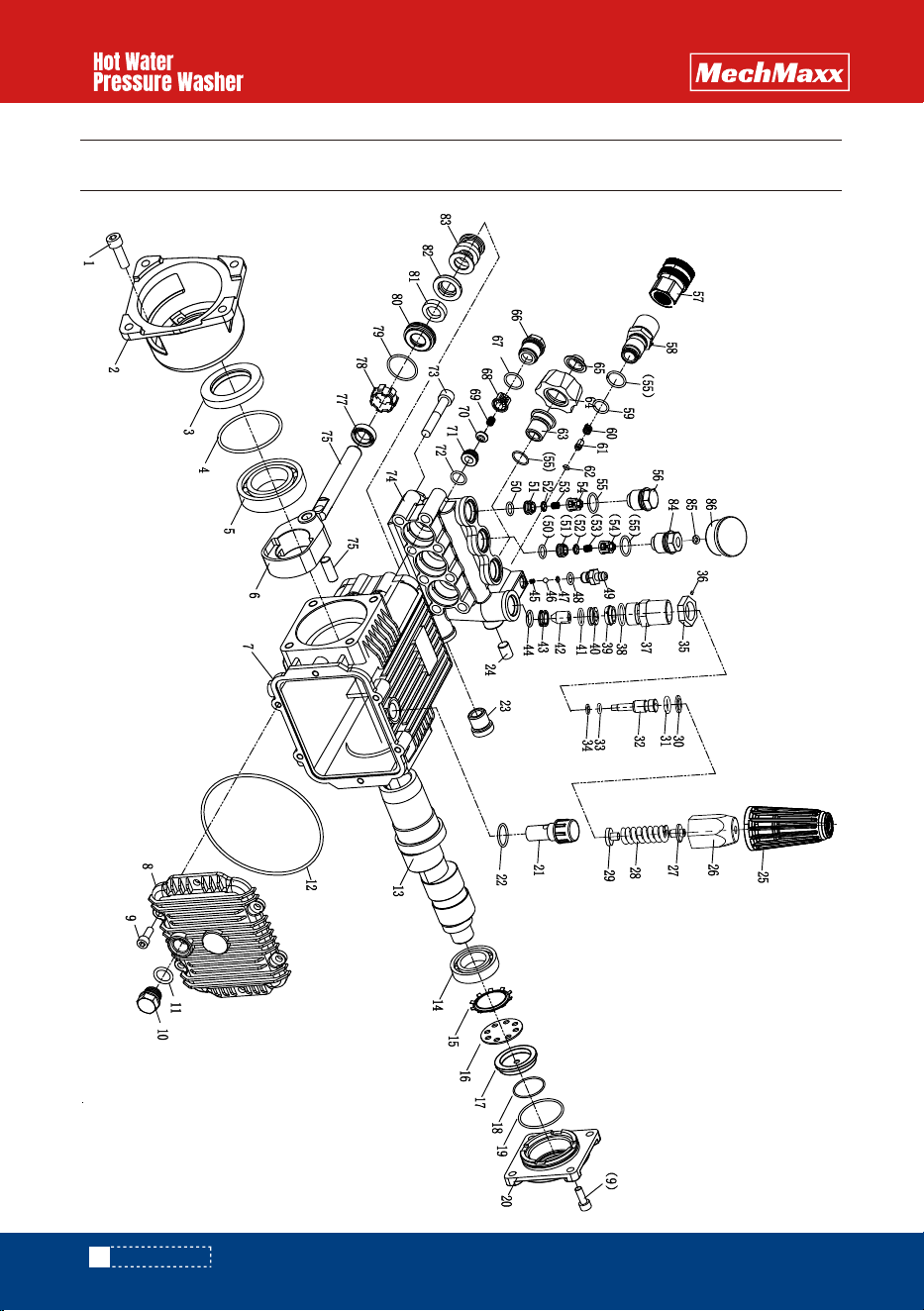
PUMP DIAGRAMS
48
www.mechmaxx.com
PUMP DIAGRAMS
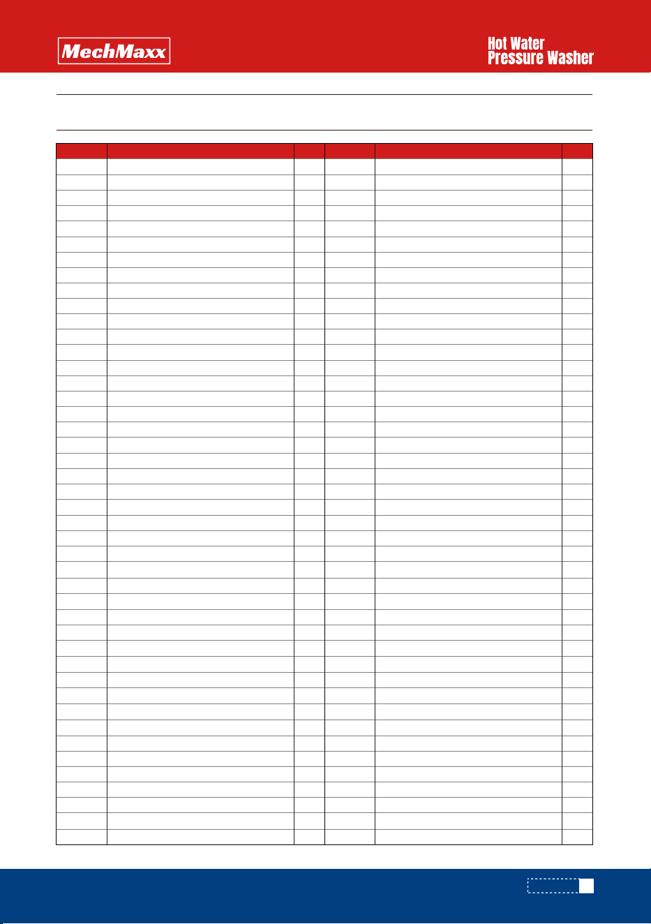
Qty.
1
2
3
4
5
6
7
8
9
10
11
12
13
14
15
16
17
18
19
20
21
22
23
24
25
26
27
28
29
Screw M8x25-8.8 grade
Connector flange
Oil seal38*58*8
O-ring63*2.65
Ball Bearing 6008
Connecting rod
Housing
Back cover
Screw M6*16-8.8 grade
Oil drain plug
O-ring 13.2*2.65
O-ring 112*2.65
Crank shaft
Ball Bearing 6304
Jump ring
Oil Window gasket
Oil Window
O-ring 47.5*1.8
O-ring 32.5*2.66
End Cap
Venting plug
O-ring 13.2*1.8
R 3/8 plug-8.8 grade
R 1/8 plug-8.8 grade
Pressure adjusting handle
Valve cover
Spring washer
Pressure adjusting spring
Spring cover
Back-up ring 10.8*15.55*1.5
O-ring 10.6*2.65 90 degree
Valve core
Back-up ring 6*9*1.25
O-ring 6*1.8 90 degree
Limit washer
Set screws M4*4
Valve body
O-ring 17*1.8 90 degree
Support
Lower seat
O-ring 12.5*1.8(90 degree)
Valve core head
Conical valve seat
O-ring 10*1.8(90 degree)
4
1
1
1
1
3
1
1
1
1
1
1
10
1
1
1
1
1
1
1
1
1
1
1
1
1
1
1
1
1
1
1
1
1
1
1
1
1
1
1
1
1
1
1
1
1
1
1
1
3
3
3
3
3
5
2
3
1
3
1
1
1
1
1
1
3
3
3
3
3
3
3
8
1
3
3
3
3
3
3
3
3
3
1
2
1
Injector liquid spring
Steel ball Φ3/16
O-ring 3.68*1.78
O-ring 7.65*1.78
Injector
O-ring 9*1.8(80 degree)
Valve seat
Valve plate
Valve spring
Valve cover
O-ring 15*1.8(90 degree)
Bulkhead
NPT3/8 quick connector
Outlet connector
O-ring 12.5*1.8(90 degree)
Check Valve spring
Check Valve core
O-ring 4.5*2.65(90 degree)
Inlet connector
Nut(brass)
Inlet filter
Inlet valve plug head
O-ring 14*1.8(90 degree)
Valve cover
Valve spring
Valve plate
Valve seat
O-ring 11.8*1.8(90 degree)
Screw M8*55-12. grade
Pump head
Cylindrical pin 9*23
Piston
Reciprocating oil
Positioning sleeve
O-ring 25.8*1.8(80 degree)
Secondary seal seat
Secondary seal 14*21*5.5
Water seal seat
Water seal seat (PARKER)
Pressure gauge connector
Plastic washer 6*12*2
Pressure gauge
30
31
32
33
34
35
36
37
38
39
40
41
42
43
44
81
82
83
84
85
86
DescriptionPart # Qty.DescriptionPart #
79
80
48
49
50
45
46
47
51
52
53
54
55
56
57
58
59
60
61
62
63
64
65
66
67
68
69
70
71
72
73
74
75
76
77
78
PARTS LIST
www.mechmaxx.com
49
PARTS LIST