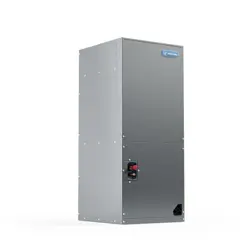
PRODIRECT™ Series
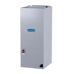
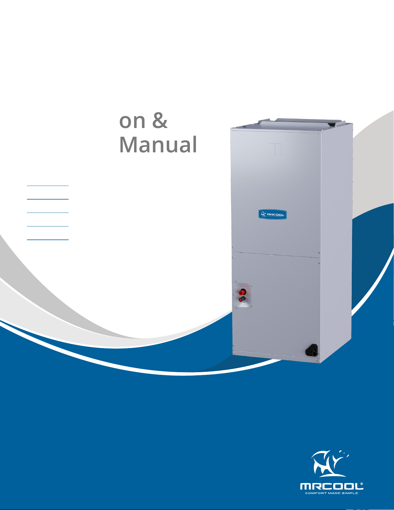
PSC Air Handler
Installation &
Owner’s Manual
MODELS:
Read this manual carefully before installation and keep it where
the operator can easily nd it for future reference.
Due to updates and constantly improving performance, the
information and instructions within this manual are subject to
change without notice.
Version Date: 12/30/2024
Please visit www.mrcool.com/documentation
to ensure you have the latest version of this manual.
HAH018FPA
HAH024FPA
HAH036FPA
HAH048FPA
HAH060FPA

mrcool.com1
CONTENTS
SAFETY PRECAUTIONS ..................................................................................................... 2
UNIT OVERVIEW ................................................................................................................ 3
2.1 Location Selection ............................................................................................... 3
2.1 Unit Dimensions .................................................................................................. 5
INSTALLATION .................................................................................................................. 6
3.1 Vertical Upow .................................................................................................... 6
3.2 Vertical Downow ............................................................................................... 6
3.3 Horizontal ............................................................................................................. 7
3.4 Installation in an Unconditioned Space ............................................................ 8
ELECTRICAL WIRING ......................................................................................................... 9
4.1 Power Wiring ........................................................................................................ 9
4.2 Control Wiring ...................................................................................................... 9
4.3 Grounding ............................................................................................................. 9
4.4 Electrical Data .................................................................................................... 10
4.5 Electric Kit MCA/MOP Data ............................................................................... 10
AIRFLOW PERFORMANCE .............................................................................................. 11
DUCTWORK ..................................................................................................................... 13
REFRIGERANT CONNECTIONS....................................................................................... 14
7.1 Condensate Drain Tubing ................................................................................. 14
AIR FILTER ....................................................................................................................... 15
WIRING DIAGRAMS ........................................................................................................ 17
PISTON/TXV INSTALLATION .......................................................................................... 20
1
2
3
4
5
Contents
8
6
7
9
8
mrcool.com 2 2
Incorrect usage may cause serious damage or injury.
The symbols below are used throughout this manual to indicate instructions that should be
followed closely or actions that should be avoided to prevent death, injury, and/or property
damage.
Safety Precautions
CAUTION
Indicates the possibility of personal injury or loss of life.
Indicates the possibility of property damage or serious
consequences.
Read Before Using
WARNING
WARNING
1. These instructions are intended as an aid to qualied licensed service personnel for proper installation,
adjustment, and operation of this unit. Read these instructions thoroughly before attempting installation
or operation. Failure to follow these instructions may result in improper installation, adjustment, service, or
maintenance possibly resulting in re, electrical shock, property damage, personal injury, or death.
2. This appliance is not intended for use by persons (including children) with reduced physical, sensory or
mental capabilities, or lack of experience and knowledge, unless they have been given supervision or
instruction concerning use of the appliance by a person responsible for their safety.
3. Children should be supervised to ensure that they do not play with the appliance.
4. This unit can't be used outdoors.
5. Because of possible damage to equipment or personal injury, installation, service, and maintenance should
be performed by a trained, qualied service personnel. Consumer service is recommended only for lter
cleaning/replacement. Never operate the unit with the access panels removed.
6. The rst 6 inches of supply air plenum and ductwork must be constructed of sheet metal as required by
NFPA 90B. The supply air plenum or duct must have a solid sheet metal bottom directly under the unit
with no openings, registers or exible air ducts located in it. If exible supply air ducts are used, they may
be located only in the vertical walls of rectangular plenum, a minimum of 6 inches from the solid bottom.
Metal plenum of duct may be connected to the combustible oor base, if not, it must be connected to the
unit supply duct exposed to the supply air opening from the downow unit. Exposing combustible (non-
metal) material to the supply opening of a downow unit can cause a re resulting in property damage,
personal injury or death.
7. Exception warning to downow: Installations on concrete oor slab with supply air plenum and ductwork
completely encased must be not less than 2 inches of concrete (See NFPA 90A).
SAFETY
1
ELECTRICAL WARNINGS
1. Disconnect power to the unit before installing or servicing. More than one disconnect switch may be
required to de-energize the equipment. Hazardous voltage can cause severe personal injury or death.
2. If removal of the blower assembly is required, all disconnect switches supplying power to the equipment
must be de-energized and locked (if not in sight of unit) so the eld power wires can be safely removed
from the blower assembly. Failure to do so can cause electrical shock resulting in personal injury or death.
3. The unit must be permanently grounded. Failure to do so can result in electrical shock causing personal
injury or death.
mrcool.com3
UNIT OVERVIEW
2
WARNING: PROPOSITION 65
• This appliance contains berglass insulation. Respirable particles of berglass are known to the state of
California to cause cancer.
• All manufacturer products meet current federal OSHA Guidelines for safety. California Proposition 65 warnings
are not required for certain products, which are not covered by the OSHA standards.
• California's Proposition 65 requires warnings for products sold in California that contain or produce any of
over 600 listed chemicals known to the state of California to cause cancer or birth defects such as berglass
insulation, lead in brass, and combustion products from natural vapor.
• All "new equipment" shipped for sale in California will have labels stating that the product contains and/or
produces Proposition 65 chemicals. Although we have not changed our processes, having the same label on all
our products facilitates manufacturing and shipping. We cannot always know when or if products will be sold in
the California market.
• You may receive inquiries from customers about chemicals found in, or produced by, some of our heating
and air conditioning equipment, or found in natural vapor used with some of our products. The following
are those chemicals and substances commonly associated with similar equipment in our industry and other
manufacturers: glass wool (berglass) insulation, carbon monoxide (CO), formaldehyde, benzene
• More details are available on the following websites: www.osha.gov and www.oehha.org
• Consumer education is important since the chemicals and substances on the list are found in our daily lives.
Most consumers are aware that products present safety and health risks, when improperly used, handled, and
maintained.
2.1 Location Selection
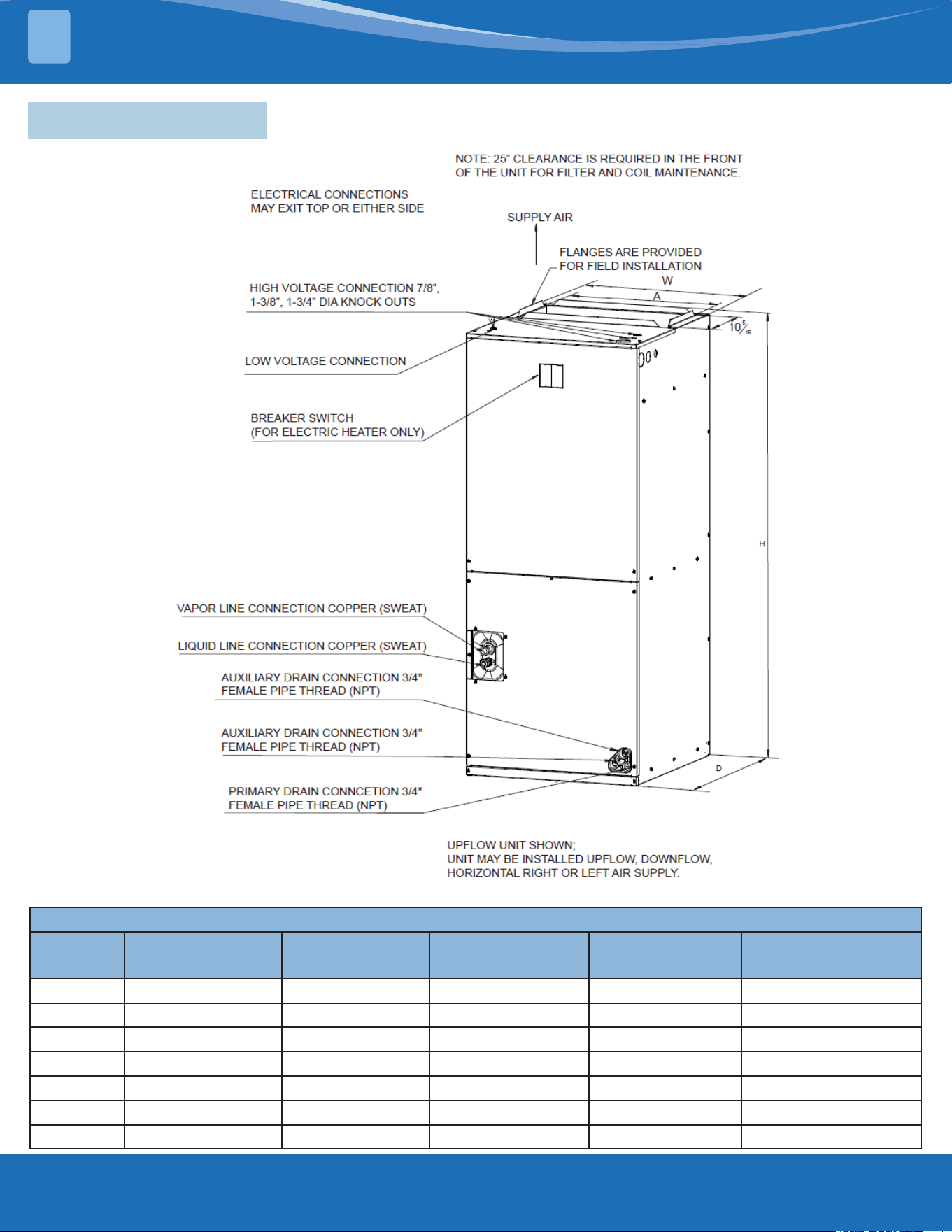
The unit can be positioned for bottom return air in the upow position, left and right return in the horizontal
position, top return in downow position.
This Air Handler provides the exibility for installation in any upow or downow horizontal application. The
direct drive motors provide a selection of air volume to match any application. 3-Speed motors provide selections
of air ow to meet desired applications.
Top and side power and control wiring, accessible screw terminals for control wiring all combine to make the
installation easy, and minimize installation cost.
Do not install unit in an area where ammable materials are present due to the risk of an explosion resulting in
serious injury or death.
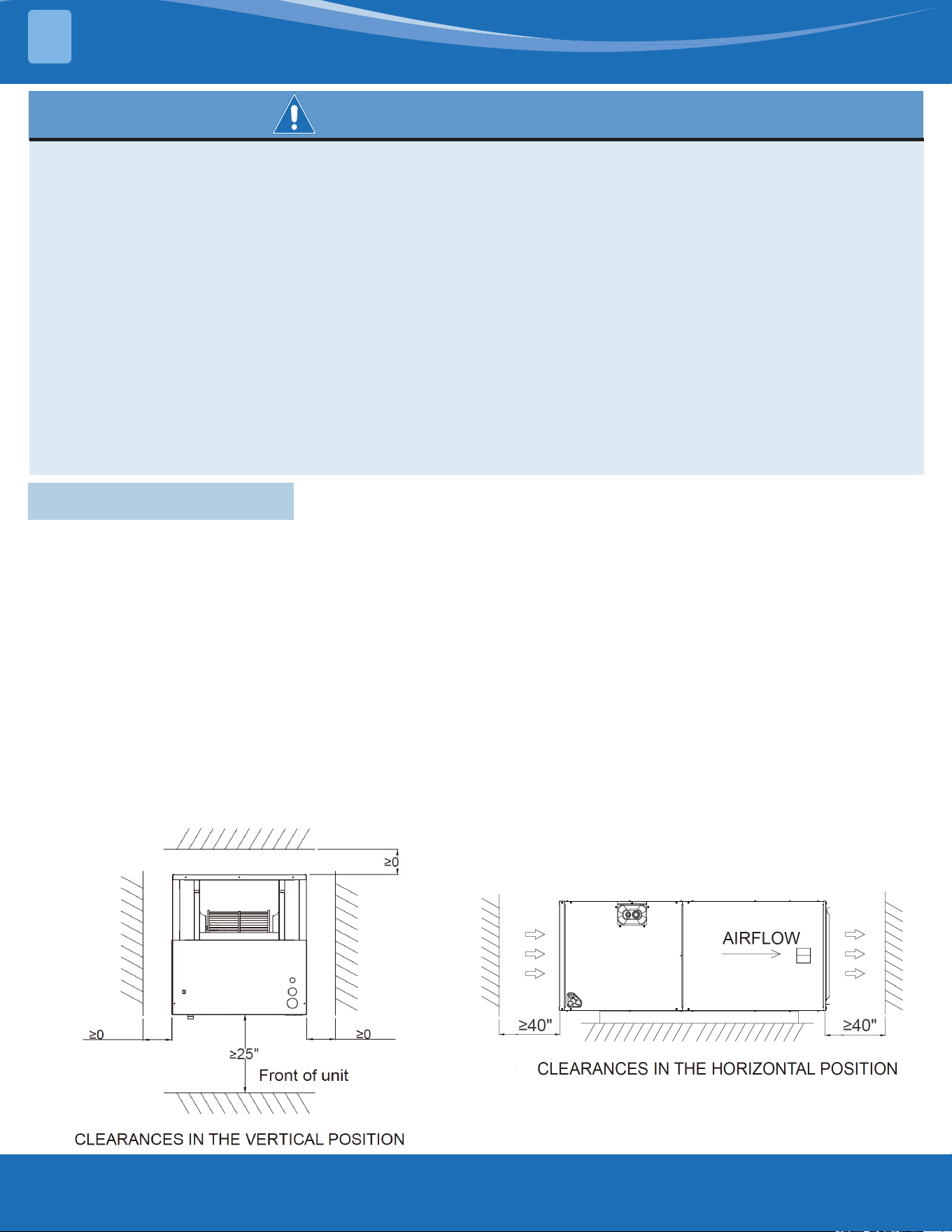
The unit should be installed in a level position to ensure proper condensation drainage. Up to an additional 1/4"
rise over the width or depth of the unit is allowed to create additional sloping towards the drain. The unit must be
positioned between level and 1/4" rise, sloping toward the drain connections.
Install the indoor and outdoor unit, power supply wiring and connecting wires at least 3.5 ft. away from televisions
or radios in order to prevent image interference or noise.
mrcool.com 4
4
WARNING
If the supporting structural members are not strong enough to support the unit's weight, the unit could fall out
of place and cause serious injury.
If a return-air duct is not installed, carefully select the place and method of product installation so that airow
into the product will not be blocked.
When the unit is installed in a hot and humid place, if the humidity inside the installation space might exceed 86°F
(30°C) and RH 80%, it is recommended to insulate the cabinet exterior.
Use glass wood or polyethylene foam as insulation so that the thickness is more than 2 in. and ts inside the
installation space opening.
Respectively, condensation may form on the surface of the insulation.
Be sure to use insulation that is designed for use with HVAC Systems.
Condensation may form on the product during cool operation.
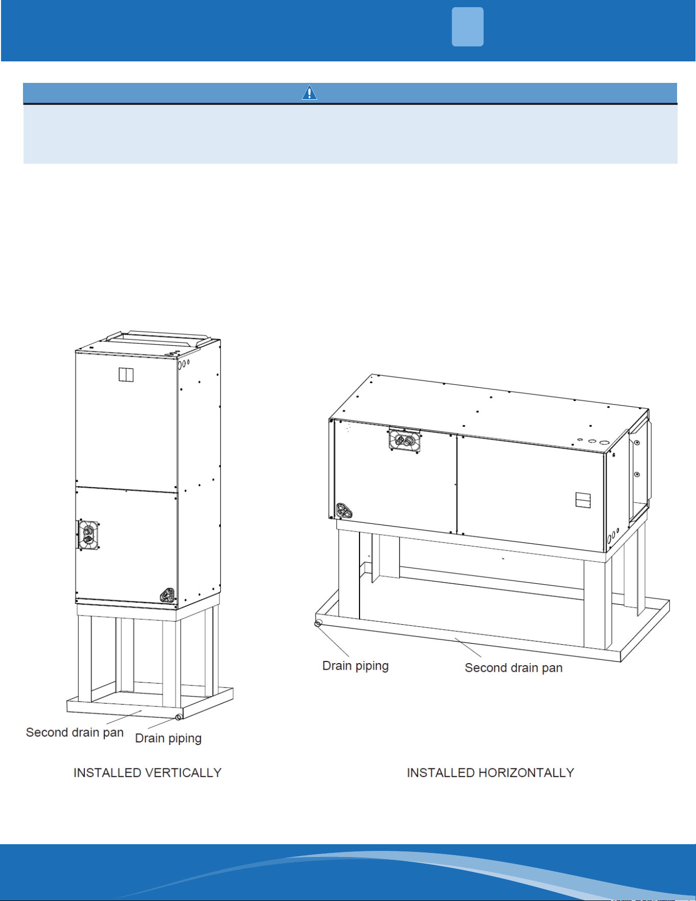
It is also recommended to use the second drain pan and secure the unit rmly to prevent it from falling.
UNIT OVERVIEW
2
mrcool.com5
UNIT OVERVIEW
2
2.2 Unit Dimensions
Unit Dimensions
Model
Height
(in. [mm])
Width
(in. [mm])
Length
(in. [mm])
Supply Duct "A"
Unit Weight
(lbs. [kg])
18 41-3/8" [1050] 18-1/8 [460] 20-1/2 [520] 16" [406] 106 [48]
24 46-1/2" [1180] 19-5/8" [500] 21-5/8" [550] 18" [456] 128 [58]
30 46-1/2" [1180] 19-5/8" [500] 21-5/8" [550] 18" [456] 128 [58]
36 46-1/2" [1180] 19-5/8" [500] 21-5/8" [550] 18" [456] 128 [58]
42 54-1/2" [1385] 22" [560] 24" [610] 19-1/2" [496] 157 [71]
48 54-1/2" [1385] 22" [560] 24" [610] 19-1/2" [496] 157 [71]
60 54-1/2" [1385] 22" [560] 24" [610] 19-1/2" [496] 161 [73]
mrcool.com 6
6
INSTALLATION
3
3.1 Vertical Upow
Vertical Upow conguration is the default factory
setting on all models.
If return air is to be ducted, install the duct ush with
the oor. Use a reproof resilient gasket 1/8 to 1/4 in.
thick between the ducts, unit, and oor. Set the unit on
the oor over the opening.
Torque applied to drain connections should not
exceed 15ft.lbs.
3.2 Vertical Downow
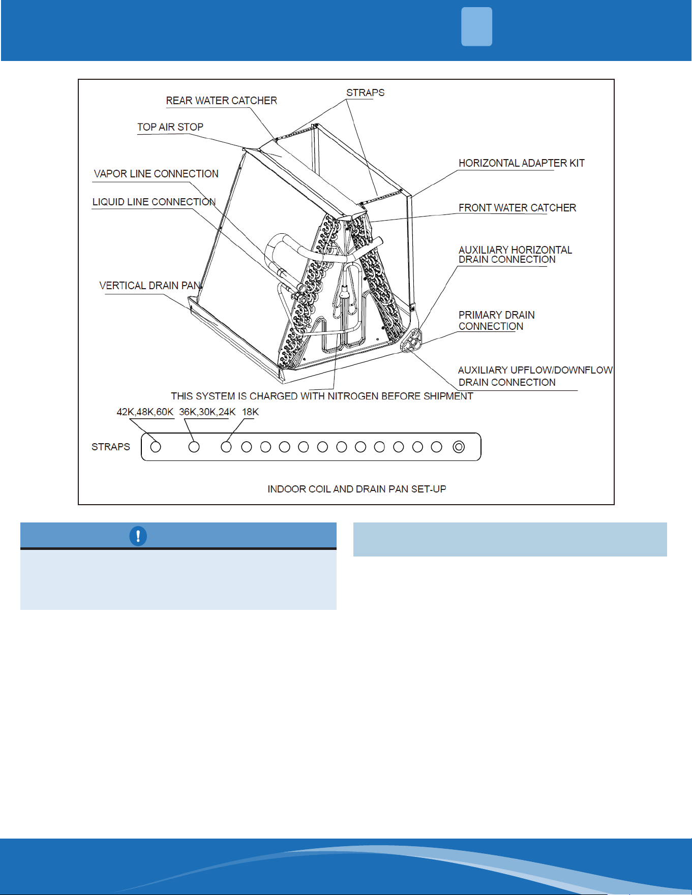
Conversion to Vertical Downow: A vertical upow
unit may be converted to vertical downow. Remove
the door and indoor coil and reinstall 180° from original
position.
IMPORTANT: To comply with certication agencies and
the National Electric Code for downow application, the
circuit breaker(s) on eld-installed electric heater kits
must be re-installed per procedure below so that the
breaker switch's "on" position and marking is up and its
"o" position and marking is down.
• To rotate breaker(s): rotate one breaker set (circuit)
at a time starting with the one on the right. Loosen
both lugs on the load side of the breaker. (Make sure
that wires are identied and are reinstalled into the
proper breaker.) Wires are bundled with wire ties,
one bundle going to the right lug and one bundle
going to the left lug.
• Using a screwdriver or pencil, lift the white plastic tab
with hole away from the breaker until the breaker
releases from the mounting opening.
• With breaker held in hand, rotate the breaker so
that its "on" position is up, and its "o" position is
down with the unit in its planned vertical mounting
position. Insert right wire bundle into the top right
breaker lug, ensuring all strands of all wires are
inserted fully into the lug, and no wire insulation is
in the lug.
• Tighten lug as tight as possible while holding the
circuit breaker. Check the wires and ensure each
wire is secure and none are loose. Repeat for left
wire bundle in the left top circuit breaker lug.
• Replace breaker by inserting breaker mounting tab
opposite the white pull tab in the opening. Hook the
mounting tab over the edge in the opening.
• With a screwdriver or pencil, pull the blue tab with
hole away from the breaker while placing that side
of the breaker into the opening. When breaker is
in place, release the tab, locking the circuit breaker
into place in the opening.
• Repeat above operation for remaining breaker(s) (if
more than one is provided).
• Replace the single point wiring jumper bar, if it is
used, on the line side of the breaker and tighten it
securely.
• Double-check all wires and lugs to make sure all are
secure and tight. Check to make sure the unit wiring
and circuit breaker load lugs match what is shown
on the unit wiring diagram.
CAUTION
When using the unit with an electrical heater, the
switch is used only for the electrical heater on the
front of the panel.
mrcool.com7
3.3 Horizontal
Horizontal right is the default factory conguration for the units.
Horizontal left is not the default factory conguration for the units.
Conversion to Horizontal left: A vertical upow unit may be converted to horizontal left by removing the indoor
coil assembly and reinstalling the coil as shown for a left-hand air supply.
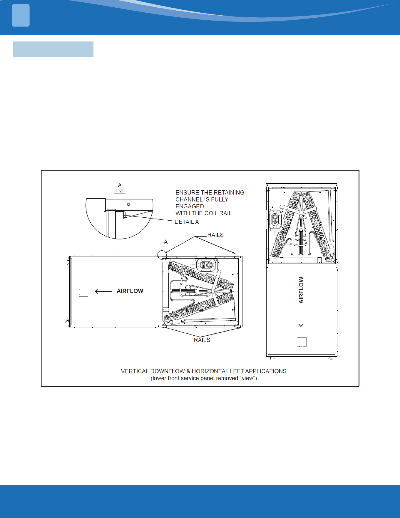
• Rotate the unit into the downow position, with the coil compartment on top and the blower compartment
on bottom.
• Reinstall the indoor coil 180° from its original position. Ensure the retaining channel is fully engaged with the
coil rail.
• Secondary drain pan kits are recommended when the unit is congured for the horizontal position over a
nished ceiling and/or living space.
INSTALLATION
3
mrcool.com 8
8
CAUTION
Horizontal units must be congured for right hand
air supply or left hand air supply. Horizontal drain
pan must be located under indoor coil. Failure to use
the drain pan can result in property damage.
Conversion in Horizontal Direction: A unit with a
horizontal right-hand supply can be changed to a
horizontal left-hand supply by removing the indoor coil
and reinstalling 180° from the original orientation.
3.4 Installation in an Unconditioned Space
IMPORTANT: There are two pairs of coil rails in the air
handler for default and counter-ow application. If the
air handler is installed in an unconditioned space, the
two unused coil rails should be removed to minimize
sweating on the air handler's surface. The coil rails can
be easily removed by taking o the 6 mounting screws
from both sides of the cabinet.
INSTALLATION
3
mrcool.com9
ELECTRICAL WIRING
4
4.1 Power Wiring
It is important that proper electrical power is available
for connection to the unit model being installed. See
the unit nameplate, wiring diagram, and electrical data
in the installation instructions.
• If required, install a branch circuit disconnect of
adequate size, located within sight of, and readily
available to the unit.
• IMPORTANT: After the Electric Heater is installed,
units may be equipped with one, two, or three 30-
60 amp. circuit breakers. These breaker(s) protect
internal wiring in the event of a short circuit and serve
as a disconnect. Circuit breakers installed within the
unit do not provide over-current protection of the
supply wiring and therefore may be sized larger
than the branch circuit protection.
• Supply circuit power wiring must be 75°C minimum
copper conductors only. See Electrical Data in this
section for ampacity, wire size, and circuit protector
requirement. Supply circuit protective devices may
be either fuses or "HACR" type circuit breakers.
• Power wiring may be connected to either the right
side, left side, or top. Three 7/8", 1-3/8", 1-3/4" dia.
concentric knockouts are provided for connection
of power wiring to unit.
• Power wiring is connected to the power terminal
block in the unit's electrical cabinet.
WARNING
Disconnect all power to the unit before performing any installation or service. More than one disconnect
switch may be required to de-energize the equipment. Hazardous voltage can cause severe personal injury or
death.
Field wiring must comply with the National Electric Code (C.E.C. in Canada) and any applicable local
ordinance.
4.2 Control Wiring
IMPORTANT: Class 2 low voltage control wiring should
not be run in conduit with main power wiring and must
be separated from power wiring, unless class 1 wire of
proper voltage rating is used.
• Low voltage control wiring should be 18 AWG color-
coded. For lengths longer than 100ft., 16 AWG wire
should be used.
• Low voltage control connections are made to low
voltage pigtails extending from the top of the air
handler.
• Connections for control wiring are made with wire
nuts. Control wiring knockouts (5/8" & 7/8") are also
provided on the right and left side of the unit for a
side connection.
• See wiring diagrams attached to indoor and outdoor
sections to be connected.
• Make sure, after installation, separation of control
wiring and power wiring has been maintained.
4.3 Grounding
WARNING
The unit must be permanently grounded. Failure to
do so can result in electrical shock causing personal
injury or death.
• Grounding may be accomplished by grounding
metal conduit when installed in accordance with
electrical codes to the unit cabinet.
• Grounding may also be accomplished by attaching
the ground wire(s) to the ground lug(s) provided in
the unit wiring compartment.
• Ground lug(s) are located close to the wire entrance
on the left side of the unit (upow). Lug(s) may be
moved to marked locations near the wire entrance
on the right side of the unit (upow), if an alternate
location is more convenient.
• Use of multiple supply circuits require grounding of
each circuit to the lug(s) provided in the unit.
mrcool.com 10
10
ELECTRICAL WIRING
4
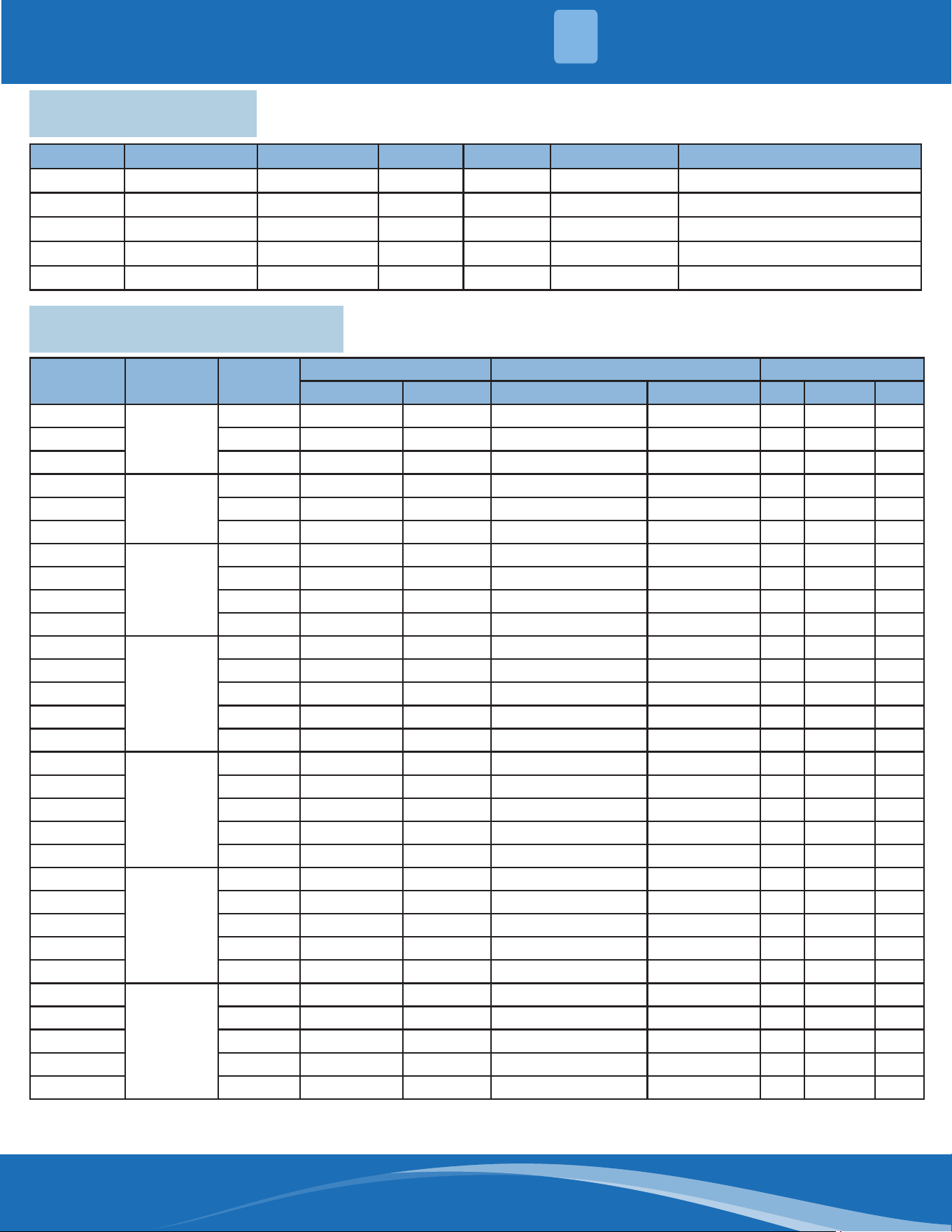
Model Voltage Hertz HP Speeds Circuit Amps. Maximum Circuit Protector
18 208/230 60 1/5 3 1.9 15(A)
24 208/230 60 1/5 3 2.6 15(A)
30/36 208/230 60 1/3 3 3.2 15(A)
42/48 208/230 60 1/2 3 4.3 15(A)
60 208/230 60 3/4 3 4.4 15(A)
4.4 Electrical Data
4.5 Electric Kit MCA/MOP Data
Heater Kit
Model Used
Air Handler
Model
Electric
Heat (kW)
Minimum Circuit Ampacity Max. Fuse or Breaker (HACR) Ampacity
Fan Speed (AC/HP)
240V 208V 240V 208V Low Medium High
HHK-05
18
5 28.1 24.6 30 25
HHK-08 7.5 41.1 35.9 45 40
HHK-10 10 54.1 47.2 60 50
HHK-05
24
5 29 25.5 30 30
HHK-08 7.5 42 36.8 45 40
HHK-10 10 55 48.1 60 50
HHK-05
30
5 29.4 25.9 30 30
HHK-08 7.5 42.4 37.2 45 40
HHK-10 10 55.4 48.5 60 50
HHK-15 15 55.4/26.1 48.5/22.6 60/30 50/25
HHK-05
36
5 29.4 25.9 30 30
HHK-08 7.5 42.4 37.2 45 40
HHK-10 10 55.4 48.5 60 50
HHK-15 15 55.4/26.1 48.5/22.6 60/30 50/25
HHK-20 20 55.4/52.1 48.5/45.2 60/60 60/50
HHK-05
42
5 30.3 26.8 35 30
―
HHK-08 7.5 43.3 38.1 45 40
―
HHK-10 10 56.3 49.4 60 50
―
HHK-15 15 55.4/26.1 49.4/22.6 60/30 50/25
―
HHK-20 20 55.4/26.1 49.4/45.2 60/60 50/50
―
HHK-05
48
5 30.3 26.8 35 30
― ―
HHK-08 7.5 43.3 38.1 45 40
― ―
HHK-10 10 56.3 49.4 60 50
― ―
HHK-15 15 56.3/26.1 49.4/22.6 60/30 50/25
― ―
HHK-20 20 56.3/52.1 49.4/45.2 60/60 50/50
― ―
HHK-05
60
5 31.8 28.3 35 30
HHK-08 7.5 44.8 39.6 45 40
HHK-10 10 57.8 50.9 60 60
HHK-15 15 57.8/26.1 50.9/22.6 60/30 60/25
HHK-20 20 57.8/52.1 50.9/45.2 60/60 60/50
• Heat pump systems require a specied air ow. Each ton of
cooling requires between 350 and 450 cubic feet of air per
minute (CFM), or 400 CFM nominally.
• Heat kit suitable for AHU 4-way installation.
• Ampacities for MCA and Fuse/breaker including the blower motor.
mrcool.com11
AIRFLOW PERFORMANCE
5
No. Kit Description Ref. Air Handler Use
1 HHK-05 5kW Heat Strip 18/24/30/36/42/48/60
2 HHK-08 7.5kW Heat Strip 18/24/30/36/42/48/60
3 HHK-10 10kW Heat Strip 18/24/30/36/42/48/60
4 HHK-15 15kW Heat Strip, double breaker panel 30/36/42/48/60
5 HHK-20 20kW Heat Strip, double breaker panel 36/42/48/60
Electric Heater Kits
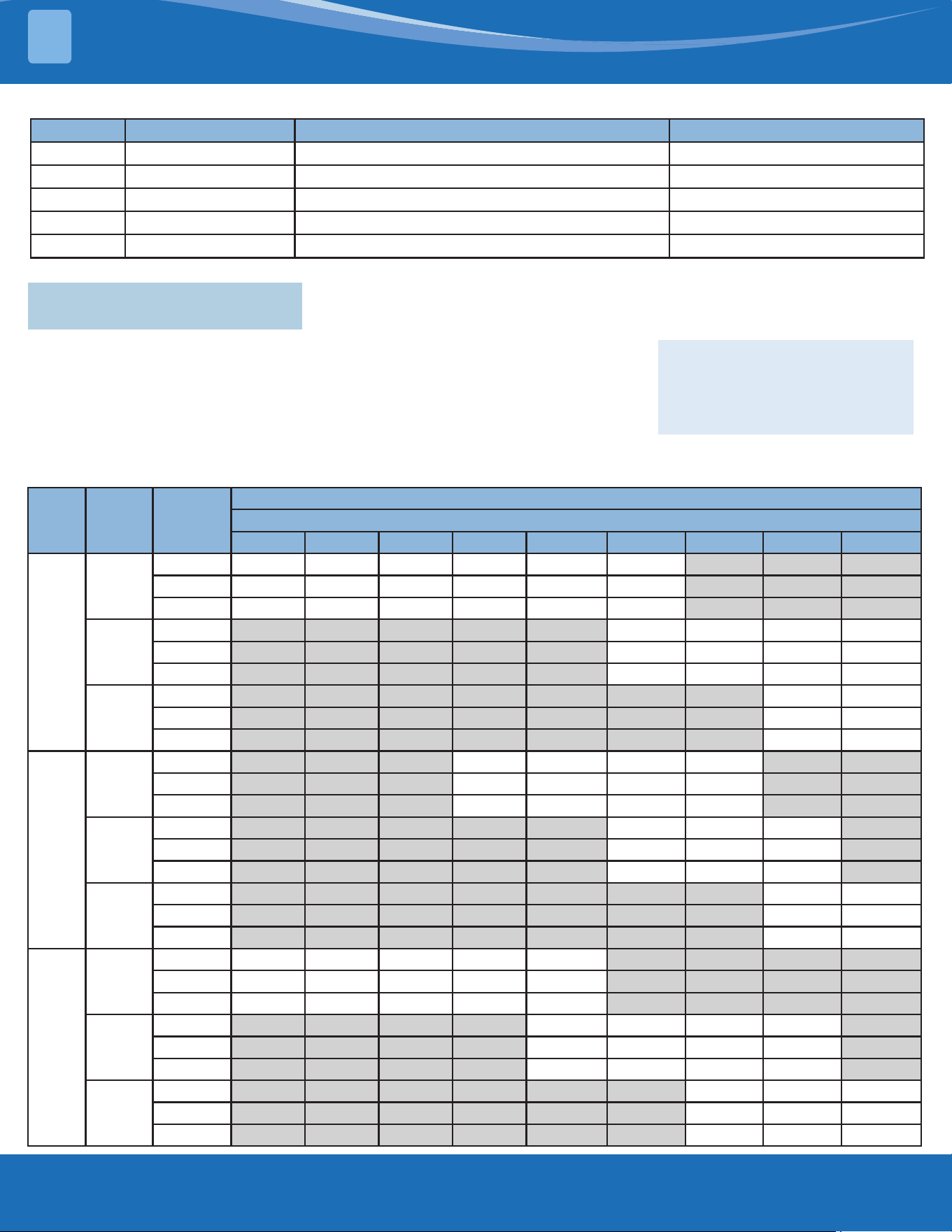
5 - Airow Performance
Airow performance data is based on cooling performance with a coil and no
lter in place. Select performance table for appropriate unit size.
External static applied to unit allows operation within the minimum and
maximum limits shown in the table below for both cooling and electric heat
operation.
Airow Performance Data
For the 36K model, in order
to achieve the AHRI 14.3
SEER2 system rating, the fan
speed must be changed from
Medium to High.
Model
Size
Motor
Speed
CFM Wet Coil Without Filter and Electric Heat
External Static Pressure-Inches W.C. [kPa]
0[0] 0.1[.025] 0.2[.050] 0.3[.075] 0.4[0.100] 0.5[0.125] 0.6[0.150] 0.7[0.175] 0.8[0.200]
18
Low
CFM 666 634 597 558 506 459 407 326 267
Watts 210 206 201 196 191 185 178 167 159
Current/A 0.92 0.89 0.88 0.86 0.84 0.82 0.79 0.75 0.72
Medium
CFM 855 835 791 744 705 657 586 528 464
Watts 240 237 232 227 222 215 207 200 191
Current/A 1.04 1.02 1.01 0.98 0.96 0.94 0.91 0.87 0.84
High
CFM 980 950 896 869 810 757 687 609 523
Power/W 308 302 298 293 282 273 262 252 240
Current/A 1.34 1.31 1.29 1.27 1.23 1.19 1.16 1.17 1.07
24
Low
CFM 999 953 905 847 757 681 610 543 411
Watts 316 310 306 302 288 279 270 256 240
Current/A 1.38 1.36 1.34 1.32 1.28 1.24 1.21 1.16 1.1
Medium
CFM 1176 1127 1086 1028 944 842 746 668 569
Watts 342 336 334 326 315 303 292 281 266
Current/A 1.49 1.47 1.45 1.42 1.38 1.33 1.29 1.25 1.19
High
CFM 1409 1359 1306 1253 1192 1108 986 870 743
Power/W 456 446 438 429 419 404 384 368 348
Current/A 2.01 1.96 1.93 1.9 1.86 1.8 1.73 1.67 1.61
30
Low
CFM 1028 985 930 859 781 712 649 571 468
Watts 362 353 345 335 323 313 303 290 276
Current/A 1.64 1.62 1.6 1.57 1.54 1.51 1.49 1.45 1.42
Medium
CFM 1315 1266 1208 1146 1065 981 866 775 686
Watts 406 399 392 385 372 361 344 331 320
Current/A 1.82 1.8 1.78 1.75 1.72 1.69 1.65 1.62 1.59
High
CFM 1532 1478 1421 1347 1284 1184 1082 932 805
Power/W 524 513 502 491 478 462 446 423 407
Current/A 2.39 2.36 2.34 2.31 2.28 2.23 2.2 2.14 2.11
mrcool.com 12
12
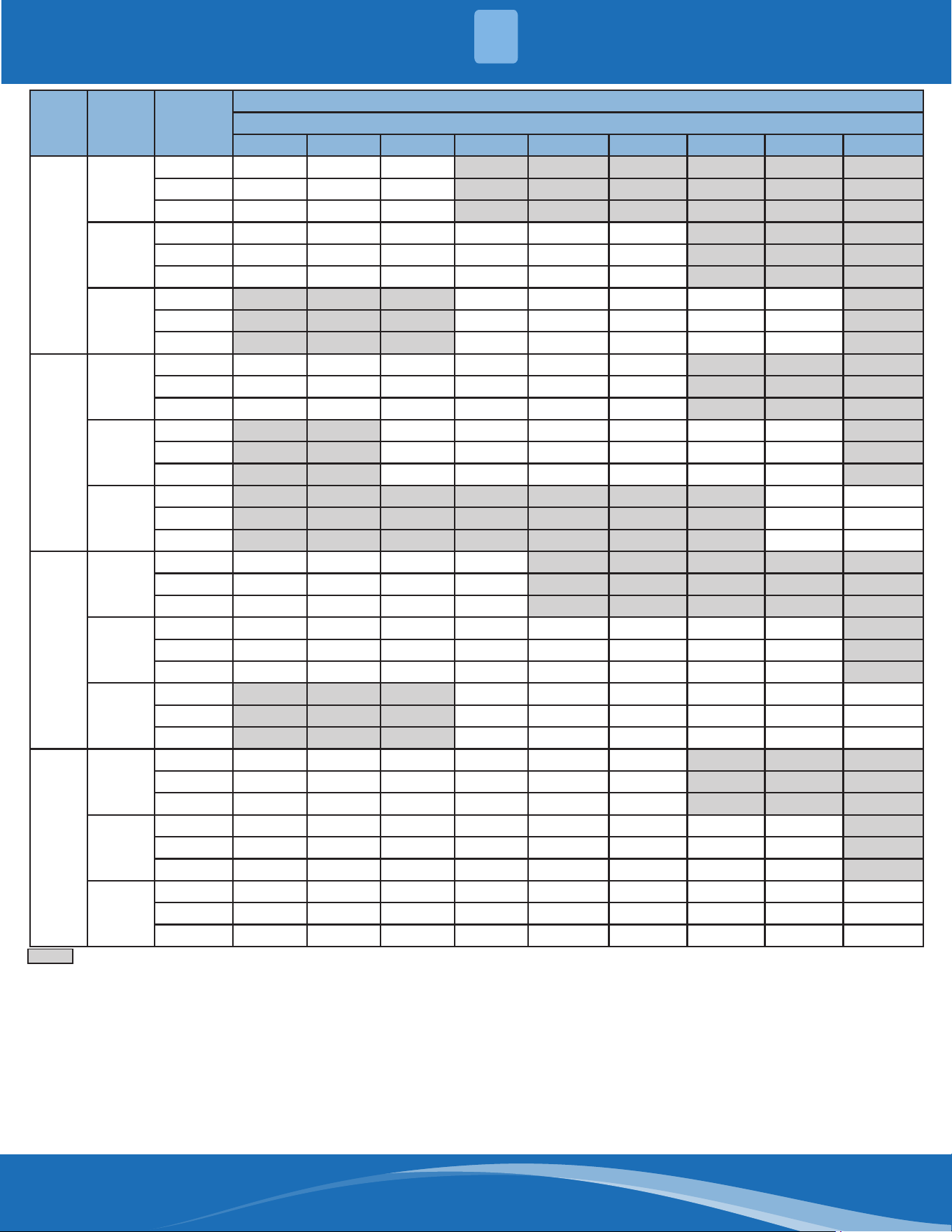
Model
Size
Motor
Speed
CFM Wet Coil Without Filter and Electric Heat
External Static Pressure-Inches W.C. [kPa]
0[0] 0.1[.025] 0.2[.050] 0.3[.075] 0.4[0.100] 0.5[0.125] 0.6[0.150] 0.7[0.175] 0.8[0.200]
36
Low
CFM 1028 985 930 859 781 712 649 571 468
Watts 362 353 345 335 323 313 303 290 276
Current/A 1.64 1.62 1.6 1.57 1.54 1.51 1.49 1.45 1.42
Medium
CFM 1315 1266 1208 1146 1065 981 866 775 686
Watts 406 399 392 385 372 361 344 331 320
Current/A 1.82 1.8 1.78 1.75 1.72 1.69 1.65 1.62 1.59
High
CFM 1532 1478 1421 1347 1284 1184 1082 932 805
Power/W 524 513 502 490 478 462 446 423 407
Current/A 2.39 2.36 2.34 2.31 2.28 2.23 2.2 2.14 2.11
42
Low
CFM 1336 1310 1282 1234 1182 1140 1049 925 833
Watts 492 483 474 463 452 443 422 393 374
Current/A 2.24 2.22 2.17 2.13 2.1 1.93 2.03 1.9 1.87
Medium
CFM 1654 1610 1569 1510 1461 1394 1350 1265 1034
Watts 550 537 526 512 503 489 475 458 416
Current/A 2.4 2.38 2.35 2.32 2.3 2.18 2.16 2.08 2.04
High
CFM 1918 1875 1817 1771 1715 1651 1584 1511 1395
Power/W 717 703 686 670 652 635 617 600 570
Current/A 3.2 3.18 3.14 3.1 3.04 3 2.9 2.87 2.85
48
Low
CFM 1336 1310 1282 1234 1182 1140 1049 925 833
Watts 492 483 474 463 452 443 422 393 374
Current/A 2.24 2.22 2.17 2.13 2.1 1.93 2.03 1.9 1.87
Medium
CFM 1654 1610 1569 1510 1461 1394 1350 1265 1034
Watts 550 537 526 512 503 489 475 458 416
Current/A 2.4 2.38 2.35 2.32 2.3 2.18 2.16 2.08 2.04
High
CFM 1918 1875 1817 1771 1715 1651 1584 1511 1395
Power/W 717 703 686 670 652 635 617 600 570
Current/A 3.2 3.18 3.14 3.1 3.04 3 2.9 2.87 2.85
60
Low
CFM 1726 1693 1655 1637 1584 1500 1421 1328 1217
Watts 678 658 639 619 602 576 553 526 495
Current/A 2.95 2.87 2.78 2.69 2.62 2.52 2.42 2.31 2.18
Medium
CFM 1983 1933 1879 1828 1760 1685 1597 1507 1403
Watts 695 675 655 635 615 596 574 550 522
Current/A 3.02 2.93 2.85 2.76 2.67 2.59 2.5 2.4 2.28
High
CFM 2138 2086 2024 1952 1873 1797 1722 1646 1516
Power/W 793 773 751 726 702 679 658 638 604
Current/A 3.45 3.7 3.27 3.17 3.06 2.97 2.88 2.79 2.65
-- Shaded boxes represent airow outside the required 300-450 cfm/
ton, which are not recommended.
-Airow based on cooling performance at 230V with no electric heat and no
lter.
-The air distribution system has the greatest eect on airow. The duct
system is totally controlled by the contractor. For this reason, the contractor
should use only industry-recognized procedures.
-Heat pump systems require a specied airow for electric heating to
operate. Each ton of cooling requires between 350 and 450 cubic feet of air
per minute (CFM), or 400 CFM nominally.
-Duct design and construction should be carefully completed. System
performance can be lowered dramatically through bad planning or
workmanship.
-Air supply diusers must be selected and located carefully. They must be
sized and positioned to deliver treated air along the perimeter of the space.
If they are too small for their intended airow, they become noisy. If they are
not located properly, they cause drafts. Return air grilles must be properly
sized to carry air back to the blower. If they are too small, they also cause
noise.
-The installers should balance the air distribution system to ensure proper
quiet airow to all rooms in the home. This ensures a comfortable living
space.
-An air velocity meter or airow hood can be used to balance and verify
branch and system airow (CFM).
-IMPORTANT: If the 18K model is converted to downow, the airow must be
between 350 and 450 cfm/ton. When used in a mobile home, the 42K model
air volume should be no less than 1335 CFM. When used in a mobile home,
the 48K model air volume should be no less than 1584 CFM.
AIRFLOW PERFORMANCE
5
mrcool.com13
DUCTWORK
6
6 - Ductwork
Field ductwork must comply with the National Fire Protection Association NFPA 90A, NFPA90B, and any applicable
local ordinance.
WARNING
• Do not, under any circumstances, connect return ductwork to any other heat producing device such as a
replace insert, stove, etc.
• Unauthorized use of such devices may result in re, carbon monoxide poisoning, explosion, personal
injury, or property damage.
Sheet metal ductwork in unconditioned spaces must be insulated and covered with a vapor barrier. Fibrous
ductwork may be used if constructed and installed in accordance with SMACNA Construction Standard on Fibrous
Glass Ducts. Ductwork must comply with National Fire Protection Association as tested by UL Standard 181 for
Class I Air Ducts. Check local codes for requirements on ductwork and insulation.
• The duct system must be designed within the range of external static pressure that the unit is designed to
operate against. It is important that the system has adequate airow. Make sure all supply and return ductwork,
grills, special lters, accessories, etc. are accounted for in total resistance. See airow performance tables in
this manual.
• Design the duct system in accordance with "ACCA" Manual "D" Design for Residential Winter and Summer Air
Conditioning Equipment Selection. Latest editions are available from: "ACCA" Air Conditioning Contractors of
America, 1513 16th Street, N.W., Washington, D.C. 20036. If duct system incorporates exible air duct, be sure
pressure drop information (straight length plus all turns) shown in "ACCA" Manual "D" is accounted for in the
system.
• Supply plenum is attached to the 3/4" duct anges supplied with the unit. Attach anges around the blower
outlet.
IMPORTANT: If an elbow is included in the plenum close to the unit, it cannot be smaller than the dimensions of
the supply duct ange on the unit.
IMPORTANT: The front ange on the return duct if connected to the blower casing must not be screwed into the
area where the power wiring is located. Drills or sharp screw points can damage insulation on wires located inside
the unit.
• Secure the supply and return air ductwork to the unit anges, using proper fasteners for the type of duct used
and tape the duct-to-unit joint as required to prevent air leaks.
mrcool.com 14
14
REFRIGERANT CONNECTIONS
7
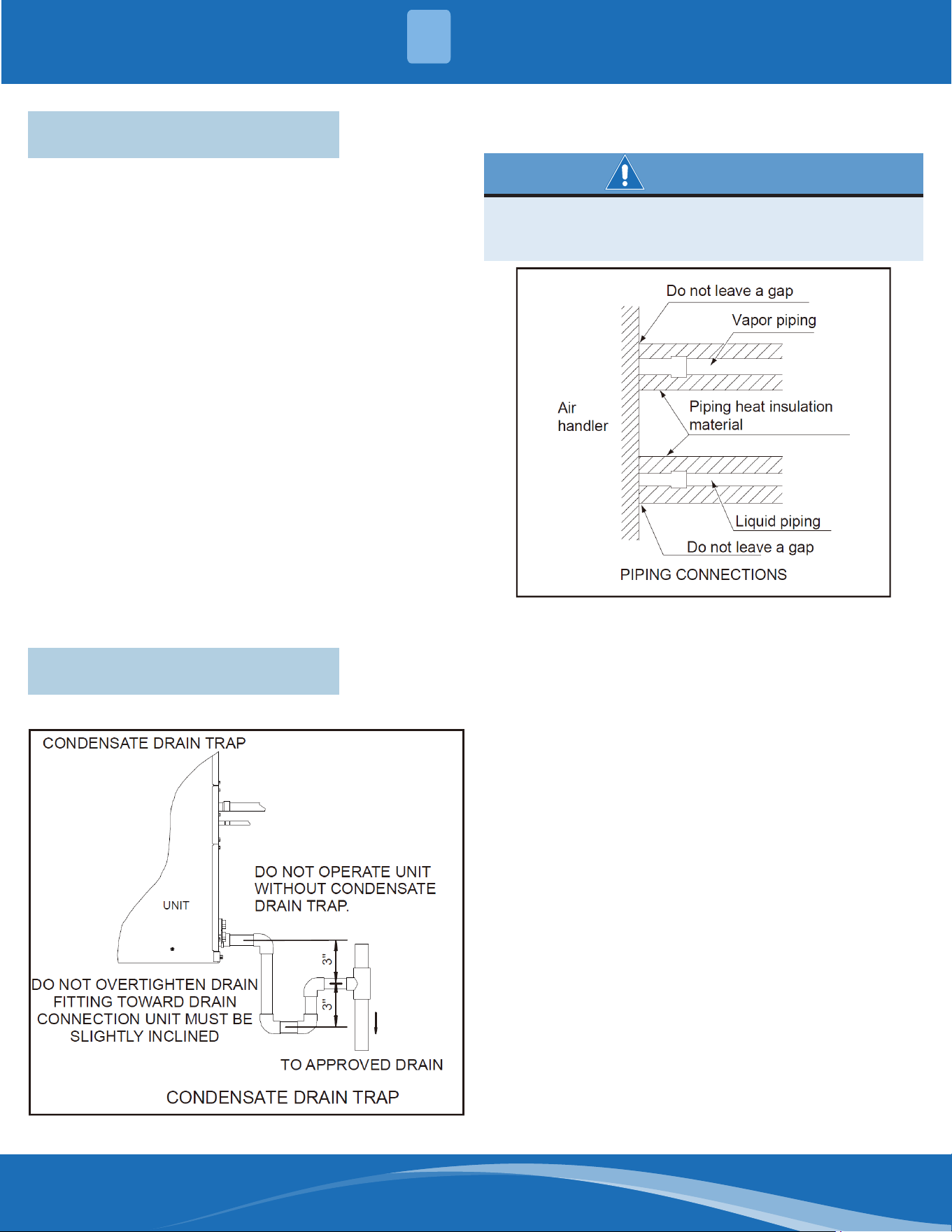
Keep the coil connections sealed until refrigerant
connections are made. See the installation instructions
for the outdoor unit for details on the line sizing, tubing
installation, and charging information.
Coil is shipped with nitrogen. Evacuate the system
before charging with refrigerant.
Install refrigerant tubing so that it does not block service
access to the front of the unit.
Nitrogen should ow through the refrigerant lines
while brazing.
Use a brazing shield to protect the cabinet's paint and a
wet rag to protect the rubber grommet and input pipe's
piston seal ring from being damaged by torch ames.
After the refrigerant connections are made, seal the
gap around the connections with a pressure sensitive
gasket.
After the work is nished, make sure to check that there
is no vapor leak. After checking for vapor leaks, be sure
to insulate the piping connections.
WARNING
Use a wet rag to protect the two seal rings in the
input pipe from being damaged by torch ames
while brazing.
7.1 Condensate Drain Tubing
Consult local codes for specic requirements.
IMPORTANT:
1. When making drain tting connections to the drain
pan, use a thin layer of Teon paste, silicone, or Teon
tape and install. Hand tighten.
2. When making drain tting connections to the drain
pan, do not over-tighten. Over-tightening ttings can
split the pipe connections on the drain pan.
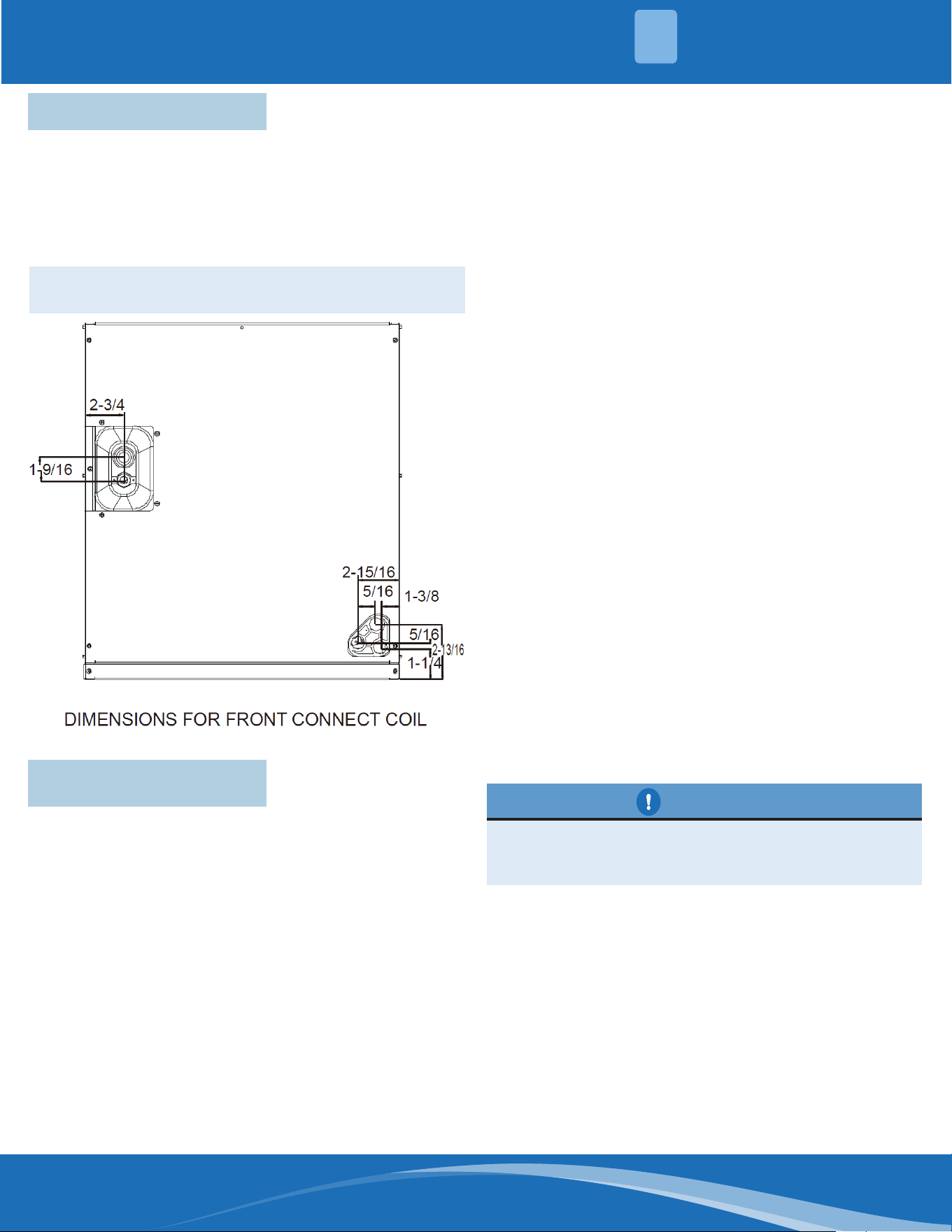
• Install drain lines so they do not block service access
to the front of the unit. Minimum clearance of 24
inches is requires for lter, coil, or blower removal
and service access.
• Make sure the unit is level or pitched slightly toward
the primary drain connection so that water will drain
completely from the pan.
• Do not reduce drain line size less than the connection
size provided on the condensate drain pan. Use 3/4"
PVC piping for drain piping connections.
• All drain lines must be pitched downward away from
the unit a minimum of 1/8" per foot of line to ensure
proper drainage.
7 - Refrigerant Connections
mrcool.com15
AIR FILTER
8
• Do not connect condensate drain line to a closed or open sewer pipe. Run condensate to an open drain or run
the line to a safe outdoor area.
• The drain line should be insulated where necessary to prevent sweating and damage due to condensate
forming on the outside surface of the line.
• Make provisions for disconnecting and cleaning of the primary drain line, should it become necessary. Install a
3 inch trap in the primary drain line as close to the unit as possible. Make sure that the top of the trap is below
the connection to the drain pan to allow complete drainage of the pan.
• The auxiliary drain line should be run to a place where it will be noticeable if it becomes operational. The
homeowner should be warned that a problem exists if water should begin running from the auxiliary drain
line.
• Plug the unused drain connection with the plugs provided in the parts bag, using a thin layer of Teon paste,
silicone, or Teon tape to form a water tight seal.
• Test condensate drain pan and drain line after installation is complete. Pour water into the drain pan, enough
to ll the drain trap and line. Check to make sure the drain pan is draining completely, no leaks are found in
the drain line ttings, and water is draining from the termination of the primary drain line.
• Be sure to insulate the drain piping and drain socket since condensation may cause water leakage.
• Be sure to install a drain trap at the drain outlet since the inside of the unit is at negative pressure to atmospheric
pressure during operation.
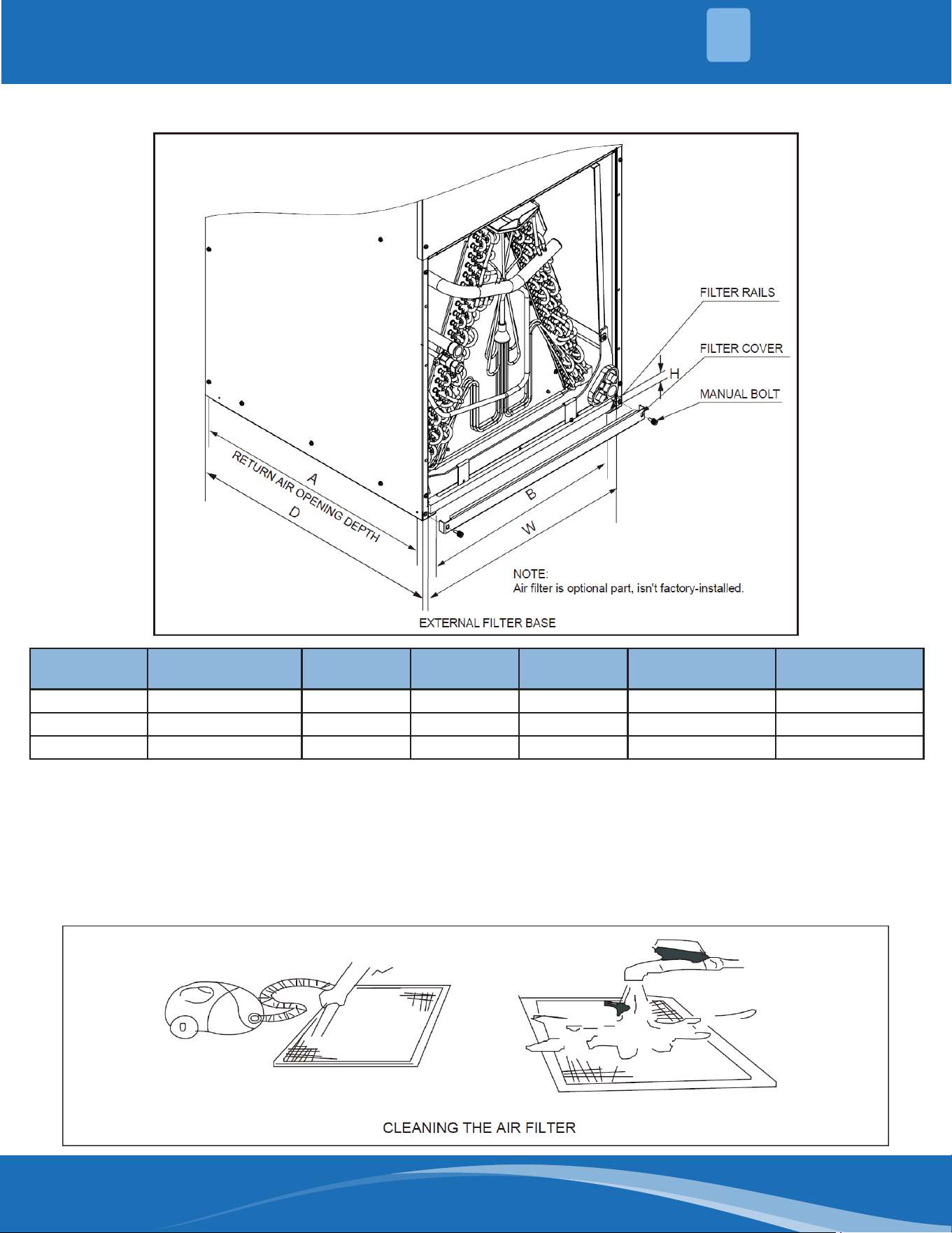
8 - Air Filter
External lter or other means of ltration is required. Units should be sized for a maximum of 300 feet/min air
velocity or what is recommended for the type of lter installed.
Filter application and placement are critical to airow, which may aect the heating and cooling system performance.
Reduced airow can shorten the life of the system's major components, such as motor, limits, elements, heat
relays, evaporator coil or compressor. Consequently, we recommend that the return air duct system have only
one lter location. Systems with a return air lter grill or multiple lter grills can have a lter installed at each of
the return air openings.
If adding high eciency lters or electronic air ltration systems, it is very important that the air ow is not
reduced. If air ow is reduced, the overall performance and eciency of the unit will also be reduced. It is strongly
recommended that a professional installation technician is contacted to ensure installation of these such ltration
systems is performed correctly.
IMPORTANT: Do not double lter the return air duct system. Do not lter the supply air duct system. This will
change the performance of the unit and reduce airow.
WARNING
Do not operate the system without lters. A portion of the dust entrained in the air may temporarily lodge in
the duct and run at the supply registers. Any circulated dust particles could be heated and charred by contact
with the air handler elements. This residue could soil ceilings, walls, drapes, carpets, and other articles in the
house.
Soot damage may occur with lters in place, when certain types of candles, oil lamps, or standing pilots are
burned.
mrcool.com 16
16
Filter Installation Dimensions
Model
Filter Size
in (mm)
"W"
in (mm)
"D"
in (mm)
"H"
in (mm)
Return Width "A"
in (mm)
Return Length "B"
in (mm)
18K 16X20 [406X508] 16.8[426] 20.4[518] 1[25.4] 19.6 14.8
24K/30K/36K 18X20[457X508] 18.3[466] 21.6[548] 1[25.4] 20.8 16.3
42K/48K/60K 20X22[508X559] 20.7[526] 23.9[608] 1[25.4] 23 18.8
Air Filter Removal
1. Remove the bolts manually, and remove the air lter cover.
2. Hold the edge of the air lter and extract out.
3. Clean the air lter (A vacuum cleaner or plain water may be used to clean the air lter. If the dust accumulation
is too heavy, use a soft brush and mild detergent to clean it and allow it to dry in a cool place.)
4. Install the new lter so that the arrow on the lter is in the same direction as airow.
AIR FILTER
8
mrcool.com17
WIRING DIAGRAMS
9
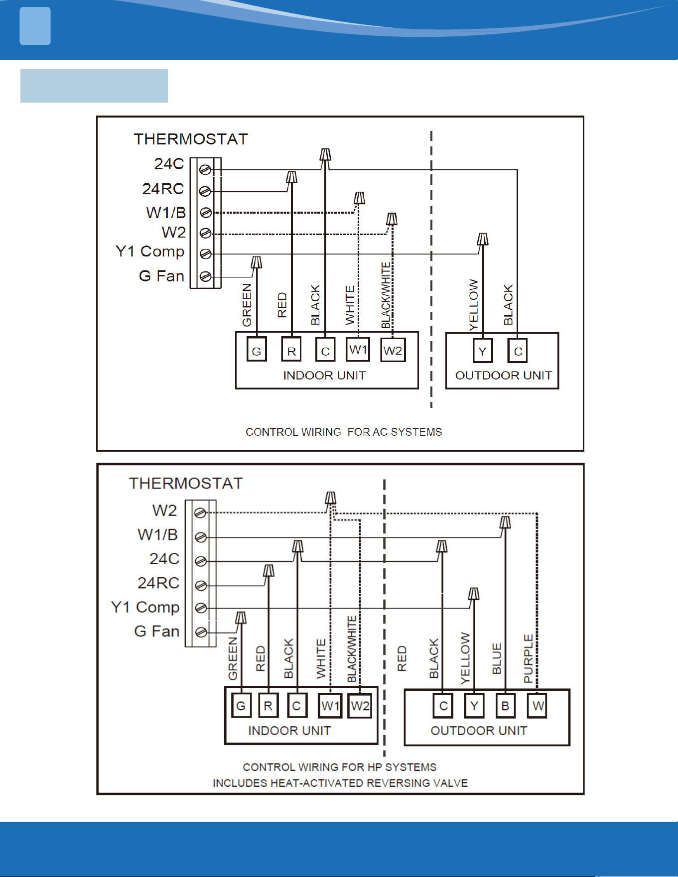
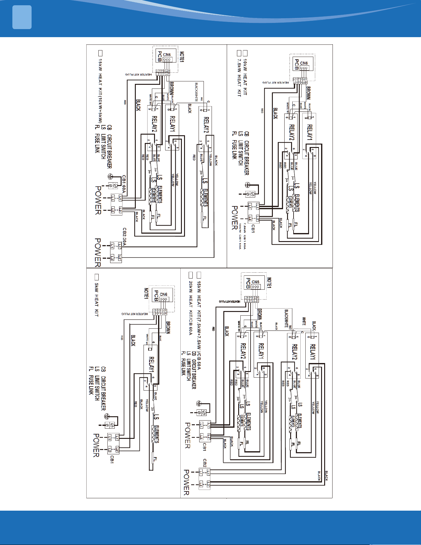
9 - Wiring Diagram
mrcool.com 18
18
WARNING
HIGH VOLTAGE!
DISCONNECT ALL POWER BEFORE SERVICING OR INSTALLING THIS UNIT. MULTIPLE POWER SOURCES
MAY BE PRESENT. FAILURE TO DO SO MAY CAUSE PROPERTY DAMAGE, PERSONAL INJURY, OR DEATH.
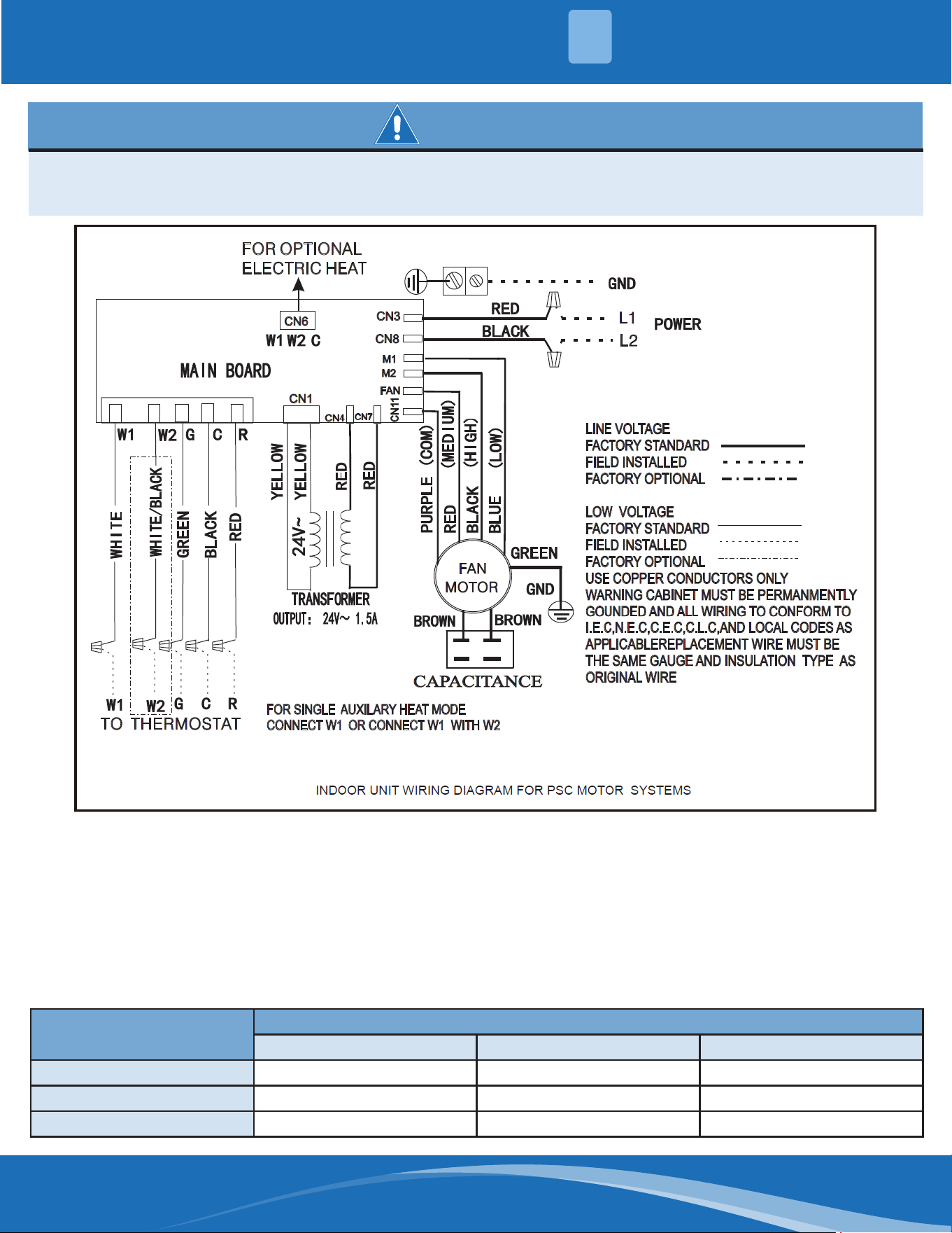
Note: Description of Fan Speed Switch with PSC Motor
1. The unit is factory-defaulted to medium speed.
2. High Speed Wiring: Switch to high speed (black wire) and connect with FAN terminal, while medium speed (red
wire) connects with the M2 terminal.
3. Low Speed Wiring: Switch to low speed (blue wire) and connect with FAN terminal, while medium speed (red
wire) connects with the M1 terminal.
4. For the 36K model, in order to make the AHRI 14.3 SEER2 system rating the fan speed must be changed from
medium to high.
Fan Speed
Terminal
Fan M1 M2
Medium Red Blue Black
High Black Blue Red
Low Blue Red Black
WIRING DIAGRAMS
9
mrcool.com19
Note: When the unit does not contain PCB boards, the short lines in the accessory bag are not needed.
Wiring is subject to change. Always refer to the wiring diagram on the unit for the most up to date wiring.
WIRING DIAGRAMS
9
mrcool.com 20
20
PISTON/TXV INSTALLATION
10
11 - Piston/TXV Installation
The coil comes with a factory-installed piston metering device. Some system combinations will require a dierent
sized piston to be eld-installed.
• Contact MRCOOL support at 270-366-0457 to order the appropriate piston kit for your system combination.
A TXV may be required to achieve minimum eciency ratings or for long refrigerant line set applications. Reference
AHRI for system combination ratings.
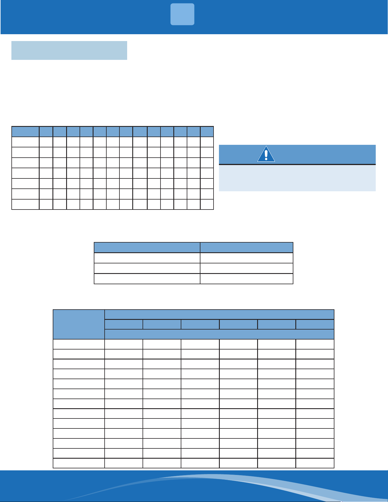
The following table shows the factory-installed piston size for each model. Additional piston sizes are provided
with the included accessories as necessary.
Model 50 52 56 58 60 64 68 70 73 75 80 83 90
18K X*
24K X*
30K X X X*
36K X X X*
42K X X*
48K X X*
60K X*
* means that this piston is pre-installed
WARNING
Failure to install the proper piston can lead
to poor system performance and possible
compressor damage.
The following table shows the optional TXV kit part numbers. Some combinations may require a TXV. See AHRI for
system combination ratings.
Outdoor Unit Capacity (Tons) R410a TXV Kit
1.5-3 MHTXV1836
3.5-4 MHTXV4248
5 MHTXV6000
Charge the system by superheat when using a piston. Reference the outdoor unit installation guide to charge the
system by subcooling when using a TXV.
Outdoor Temp
(°F)
Indoor Temperature (°F) Dry Bulb/Wet Bulb
95/79 90/75 85/71 80/67 75/63 70/58
Superheat (°F)
115 23 16 7 6 5 5
110 24 17 9 6 5 5
105 26 19 11 6 5 5
100 27 21 13 7 6 5
95 29 23 14 9 6 5
90 30 25 18 12 7 5
85 32 26 20 15 9 6
80 34 28 22 17 11 6
75 35 30 24 19 13 7
70 37 32 26 21 16 10
65 38 34 29 24 19 13
60 40 36 31 27 22 17
55 41 37 34 30 26 21

PRODIRECT™ Series
PSC Air Handler
The design and specications of this product and/or manual are subject to change without prior notice.
Consult with the sales agency or manufacturer for details.