PRODIRECT™ SERIES
Split System Heat Pump & Air Conditioner
15 SEER 1.5-5 Tons Model
HHP150* & HAC150*
Installation & User
Manual
Thank you for choosing MRCOOL. Please read this manual carefully before installation and keep it for future reference.
Copyright © 2023 MRCOOL, LLC
Due to updates and constantly improving performance, the information and instructions within this
manual are subject to change without notice. Please visit www.mrcool.com/documentation to
ensure you have the latest version of this manual.
Version Date: 5/24/2023
01 02 03 04 05 06 07 08 09 10 11 12 13 14 15 16 17 18 19
20 21 22 23 24 25 26 27 28 29 30 31 32 33 34 35 36
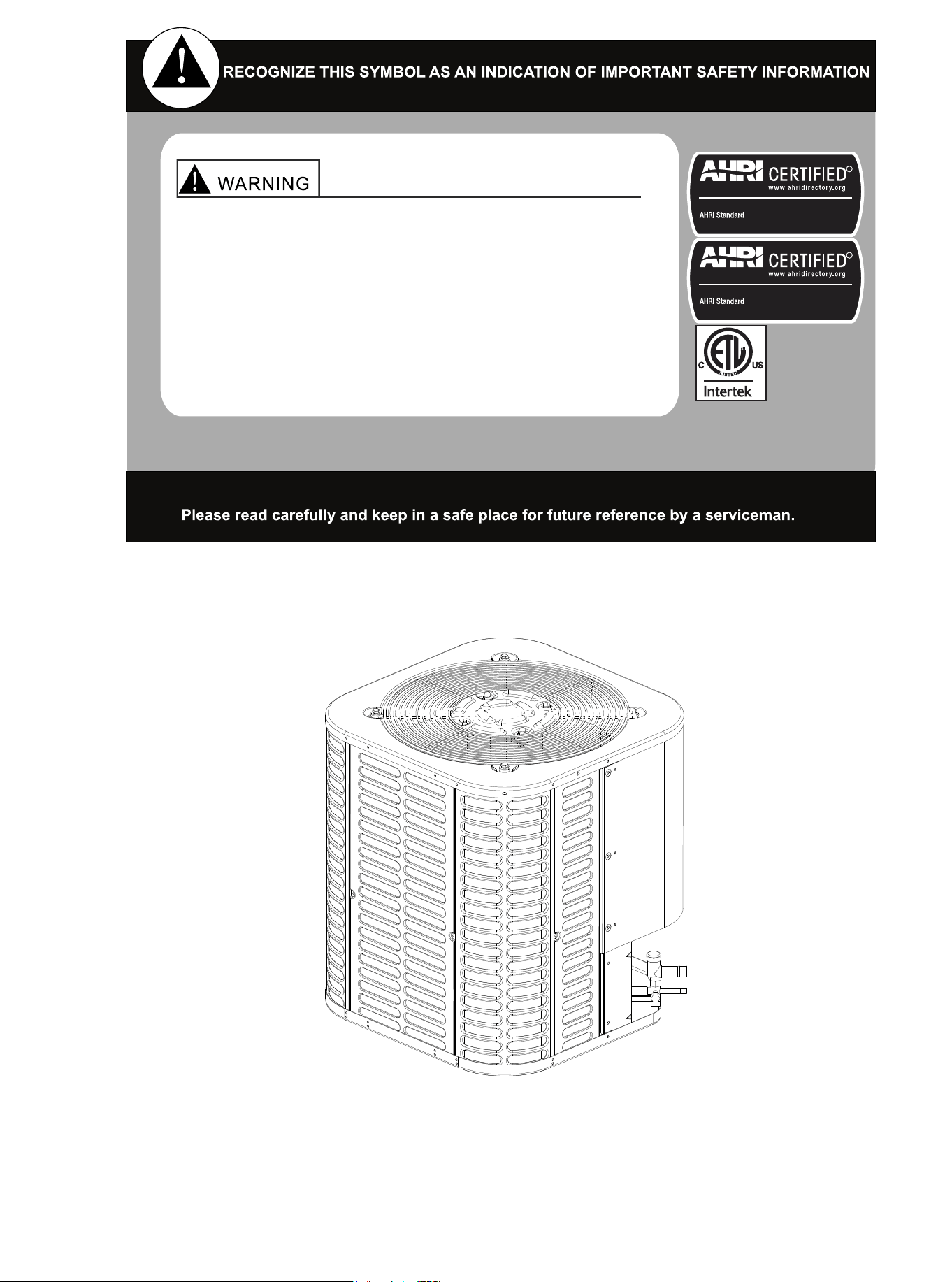
These instructions are intended as an aid for qualified
and licensed service personnel for proper installation,
adjustment, and operation of this unit. Read these
instructions thoroughly before attempting installation
or operation. Failure to follow these instructions may
result in improper installation, adjustment, service or
maintenance possibly resulting in fire, electrical shock,
property damage, personal injury or death.
R
Unitary Small AC
210/240
Certification applies only When the complete system
is listed with AHRI.
R
Unitary Small HP
210/240
Certification applies only When the complete system
is listed with AHRI.

CONTENTS
1. Symbol and Key to Safety Instructions............................................................ 01
2. Considerations of Unit Location ...................................................................... 04
3. Unit Installation Preparation ............................................................................ 08
4. Unit Settings .................................................................................................... 08
5. Precautions for Refrigerant Pipeline................................................................ 09
6. Refrigerant Pipeline Routing ........................................................................... 11
7. Refrigerant Pipeline Brazing............................................................................ 13
8. Refrigerant Pipeline Leakage Inspection......................................................... 15
9.
Evacuation ...................................................................................................... 16
10. Service Valve................................................................................................. 17
11. Electrical-Low Voltage ................................................................................... 18
12. Electrical-High Voltage .................................................................................. 23
13. Start............................................................................................................... 24
14. System Refrigerant Charging Regulation...................................................... 25
15. System Operation and Troubleshooting ........................................................ 27
16. Wiring Diagram.............................................................................................. 34
17. Cleaning and Maintenance............................................................................ 36
01 02 03 04 05 06 07 08 09 10 11 12 13 14 15 16 17 18 19
20 21 22 23 24 25 26 27 28 29 30 31 32 33 34 35 36
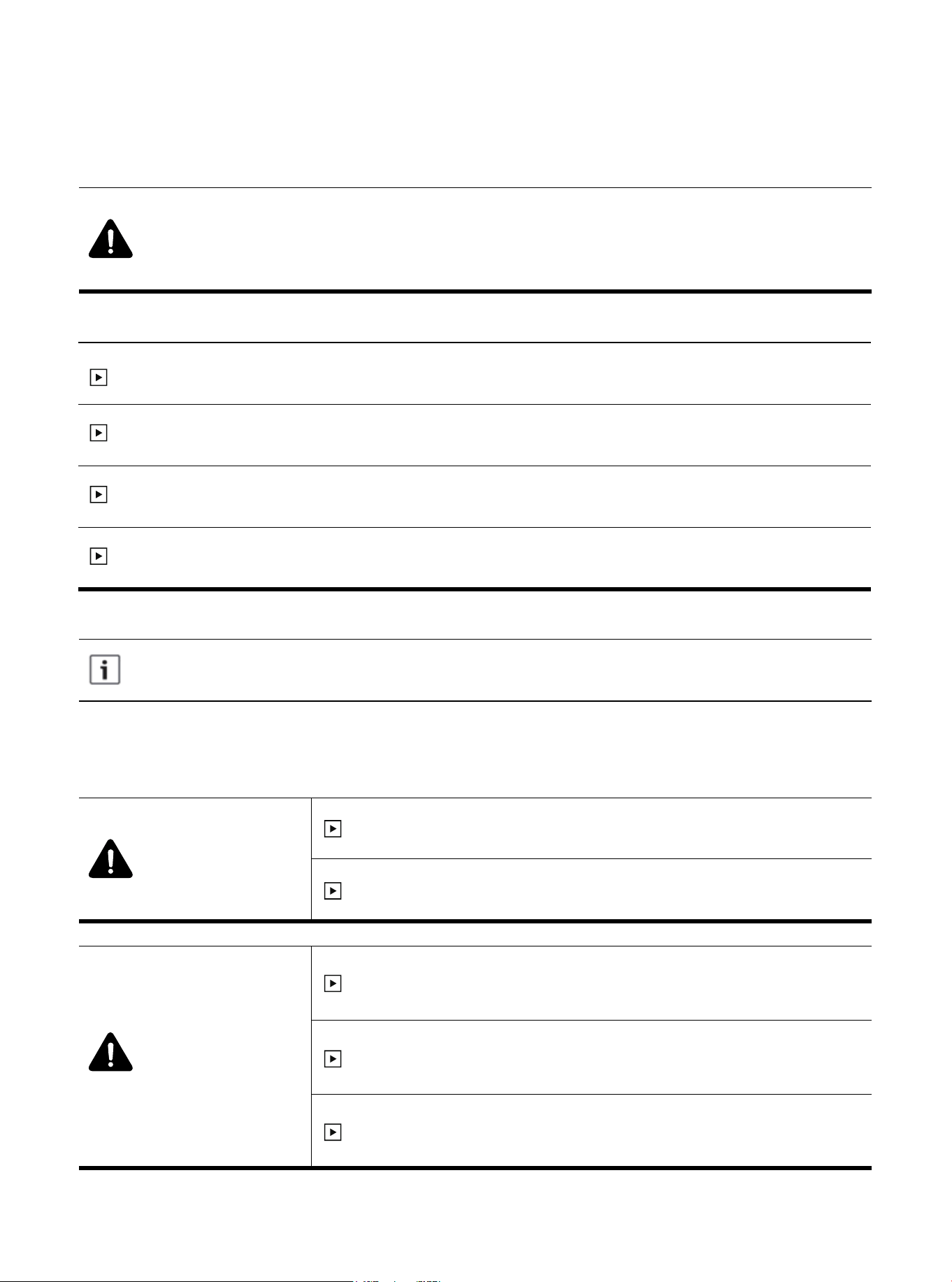
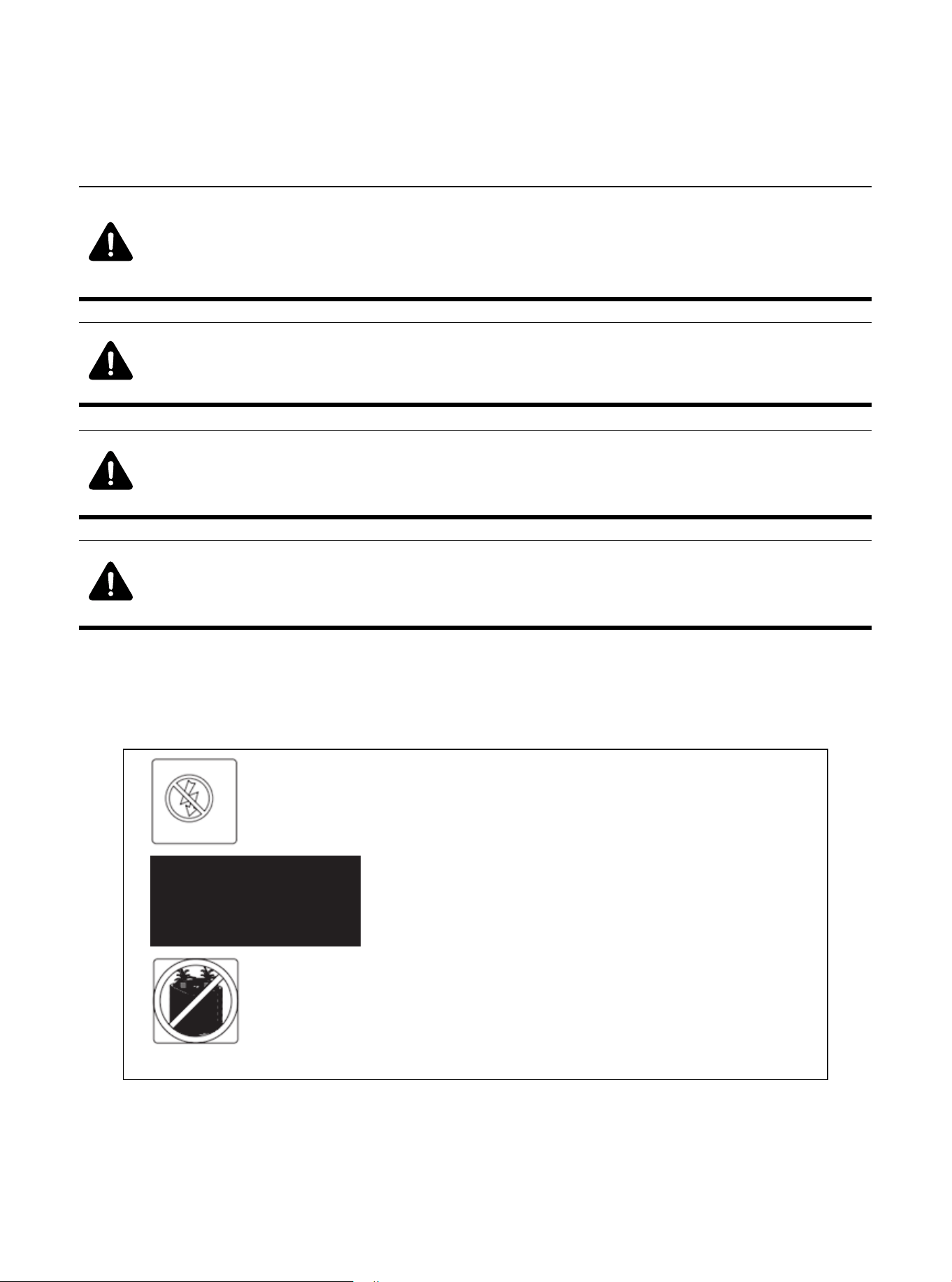
The following keywords are defined and used in this document:
Danger
Indicates a dangerous situation, which, if not avoided, will lead to
death or serious injury.
Warning
Indicates a dangerous situation, which, if not avoided, may lead to
death or serious injury.
WARNING
The warnings in this document are identified by warning triangles
printed on a gray background. The key words at the beginning of the
warning indicate the type and severity of the risk if no measures are
taken to prevent it.
WARNING
1. Symbol and Key to Safety Instructions
1.1 Symbol Keywords
1.2 Safety
Caution
Indicates a dangerous situation, which, if not avoided, may cause
mild to moderate injury.
Note
Indicates potential behaviors unrelated to personal injury.
Please Read Before Continuing.
Important information
This symbol represents important information that is not dangerous to people or property.
Failure to observe this warning may result in property damage,
serious personal injury or death.
Before touching the electrical components, wait for 3 minutes after
disconnecting the power supply.
NOTE
These instructions do not cover all changes in the system, nor do
they provide all unexpected situations that may be encountered
during installation.
This document is the property of the customer and should be
retained for any future maintenance or repair needs.
If you need more information, or there are special situations that
are not covered in this installation manual, please consult our tech
support department at (270) 366-0457.
01 02 03 04 05 06 07 08 09 10 11 12 13 14 15 16 17 18 19
20 21 22 23 24 25 26 27 28 29 30 31 32 33 34 35 36
Some benefits of installing compatible indoor and outdoor units are maximum
efficiency, best performance and best overall system reliability.
This document contains wiring diagrams and maintenance information and should be
retained by the customer in case of future repair needs.
Warning: Dangerous Voltage
● Failure to observe this warning may result in property damage, serious personal injury, or
death.
● Disconnect all power before maintenance, including remote disconnection. Follow proper
locking/tagging procedures to ensure that the power supply will not be energized accidentally.
Warning: Refrigerant Oil
● Attempting to repair central air-conditioning products without proper training may result in
property damage, serious personal injury or death. These units use R-410A refrigerant, and
its working pressure is 70% higher than R-22. Use only the service equipment approved by
R-410A. The refrigerant cylinder is painted a rose color to indicate the type of refrigerant, and
may contain a "dip" tube to allow liquid refrigerant to be filled into the system. All R-410A
systems use POE oil (VG74 or equivalent), which can easily absorb moisture from the
atmosphere. In order to limit this "moisture absorption" effect, the system should be sealed as
much as possible. If the system is exposed to the atmosphere for more than 4 hours, the
compressor oil must be changed. Do not destroy the vacuum with air, and always replace the
dryer when you open the system for component replacement.
Warning:
● This appliance is not intended for use by persons (including children) with reduced physical,
sensory or mental capabilities, or lack of experience and knowledge, unless they have been
given supervision or instruction concerning use of the appliance by a person responsible for
their safety.
● The appliance shall be installed in accordance with national wiring regulations.
● Before accessing the connection terminals, all power circuits must be disconnected.
● This information is intended for use by individuals with an experienced electrical and
mechanical background. Attempting to repair central air conditioning products without
experience may result in personal injury and/or property damage.
Warning: Hot Surface
● Touching the top of the compressor may cause mild to severe burns. Failure to
observe this caution may result in property damage or personal injury.
Caution: Contains Refrigerant
● Failure to follow the correct procedures will lead to personal illness or injury or serious equip-
ment damage. The system contains high-pressure oil and refrigerant. Before opening the
system, recover the refrigerant to release the pressure.
01 02 03 04 05 06 07 08 09 10 11 12 13 14 15 16 17 18 19
20 21 22 23 24 25 26 27 28 29 30 31 32 33 34 35 36
Note: Indoor Unit Required
● Indoor unit is equipped with piston or TXV, and the model of piston and TXV is selected by
manufacturer, please do not change by yourself.
Note: Grounding Required
● Failure to check or use the correct maintenance tools may result in equipment damage or
personal injury. Reconnect all grounding devices. All parts of this product that can conduct
current are grounded. If the grounding wire, screw, strap, clip, nut or washer used to com-
plete the grounding path is removed during maintenance, it must be put back in place and
properly secured.
War
ning: Service Valve
● Failure to observe this warning will result in sudden discharge of system charge, which may
result in personal injury and/or property damage. When opening the liquid pipeline service
valve, be extra careful. Turn the valve stem counterclockwise until the valve stem touches
the bead.
Warning: Brazing Required
● Failure to check the wiring or use the correct maintenance tools may result in equipment
damage or personal injury. If using existing refrigerant lines, ensure that all joints are
brazed, not soldered.
Warning: High Current Leakage
● Failure to observe this warning may result in property damage, serious personal injury,
or death. Before connecting the power supply, grounding is essential.
Warning:
● This product may cause exposure to chemicals including lead and lead components, which
are known in California to cause cancer, birth defects or other reproductive harm. For more
information, please visit www.P65Warnings.ca.gov.
01 02 03 04 05 06 07 08 09 10 11 12 13 14 15 16 17 18 19
20 21 22 23 24 25 26 27 28 29 30 31 32 33 34 35 36
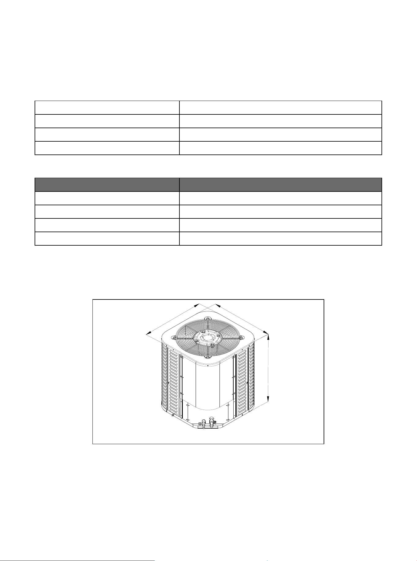
Unit size
Model
18K/24K(AC)
24K(HP)/ 30K/36K
H x W x L (inches)
25 x 21-4/5 x 21-4/5
25 x 29-1/7 x 29-1/7
42K/48K/60K 32-7/8 x 29-1/7 x 29-1/7
Table 2.2
Model
Cooling mode
General heat pump mode
Temperature
58-115℉
15-75℉
High vertical heat pump mode
23-75℉
Table 2.1 Outdoor Operating Temperature
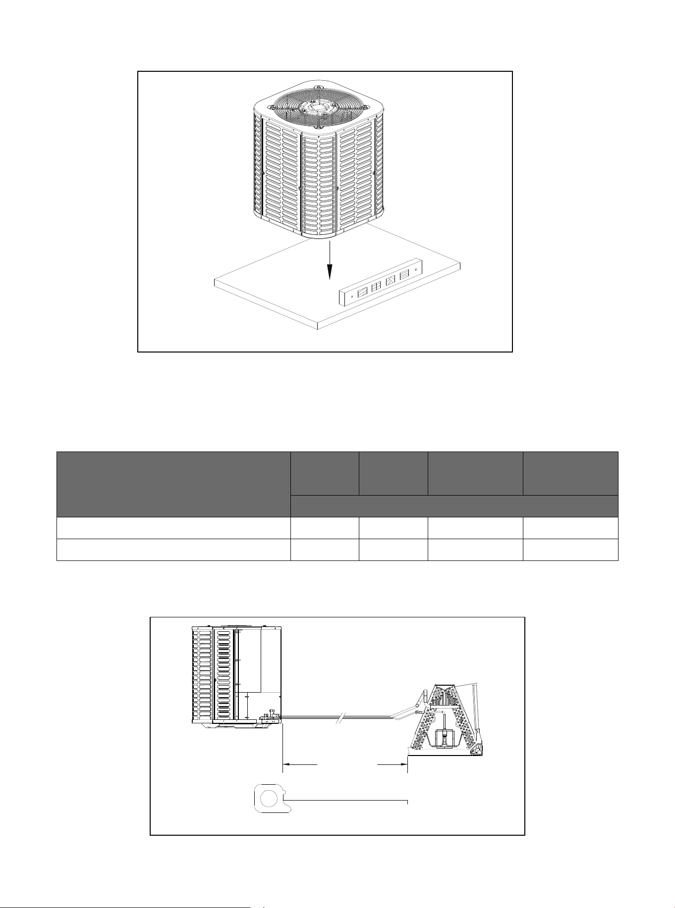
Figure 2.1
The weight of the unit is attached to the carton.
When installing the outdoor unit on the roof, make sure that the roof can support the weight of the
outdoor unit. It is recommended to choose appropriate isolation to prevent sound or vibration from being
transmitted to the building structure.
W
L
H
2. Considerations of Unit Location
2.1 Unit Size
01 03 04 05 06 07 08
09 10 11 12 13 14 15 16 17 18
19 20 21 22 23 24 25 26 27 28
29 30 31 32 33 34 35 36 37
02
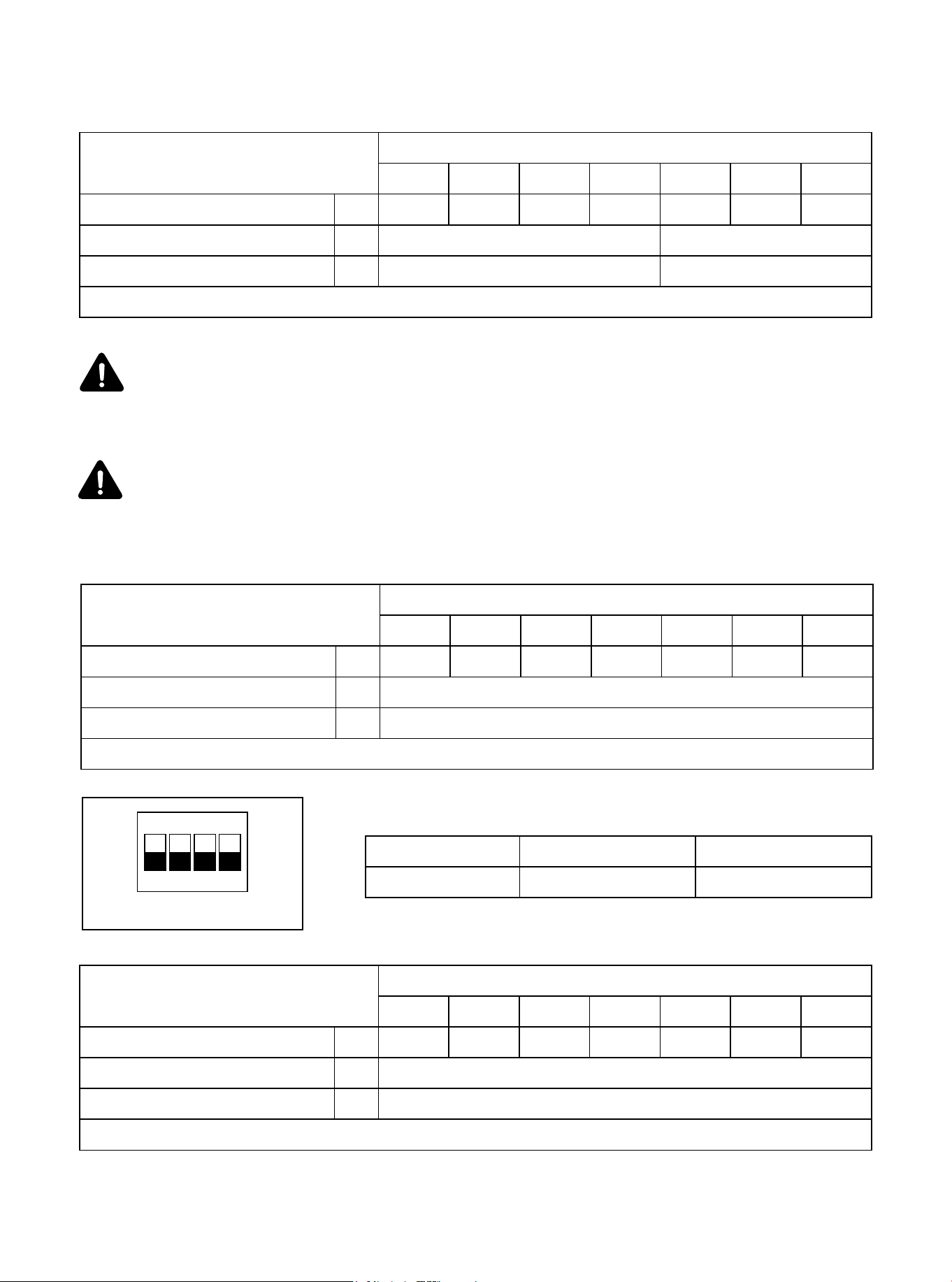
Figure 2.2
2.2 Refrigerant Pipeline Restriction
Table 2.3 Heat pump types in general mode
If the pipeline length or high vertical of the above models exceeds the data in Table 2.3, please
set the high vertical mode dial according to the data range in Table 2.4, and refer to Table 2.5 for
the dip switch diagram.
*It is recommended to adopt standard pipeline size; Refrigerant charge: see Section 14.
Refrigerant Piping
Liquid-Gas
Max. Refrigerant Line Length*
Max. Vertical Lift
In.
Ft.
Capacity (Kbtu/h)
18K
100
3/8-3/4
24K
3/8-3/4
30K
3/8-3/4
36K
3/8-3/4
42K
3/8-3/4
48K
3/8-7/8
60K
3/8-7/8
150
Ft. 26 33
Table 2.4 Heat pump types in high vertical mode
*It is recommended to adopt standard pipeline size; Refrigerant charge: see Section 14.
Refrigerant Piping
Liquid-Gas
Max. Refrigerant Line Length*
Max. Vertical Lift
In.
Ft.
Capacity (Kbtu/h)
18K
130
3/8-3/4
24K
3/8-3/4
30K
3/8-3/4
36K
3/8-3/4
42K
3/8-3/4
48K
3/8-7/8
60K
3/8-7/8
Ft. 60
Table 2.6 Cooling only types
*It is recommended to adopt standard pipeline size; Refrigerant charge: see Section 14.
Refrigerant Piping
Liquid-Gas
Max. Refrigerant Line Length*
Max. Vertical Lift
In.
Ft.
Capacity (Kbtu/h)
18K
130
3/8-3/4
24K
3/8-3/4
30K
3/8-3/4
36K
3/8-3/4
42K
3/8-3/4
48K
3/8-7/8
60K
3/8-7/8
Ft. 60
ON KE
1 3 42
Dial switch ON OFF
SW1-2 High-vertical mode General mode
Table 2.5 Dip Switch Diagram
01 03 04 05 06 07 08
09 10 11 12 13 14 15 16 17 18
19 20 21 22 23 24 25 26 27 28
29 30 31 32 33 34 35 36 37
02
Instructions for high vertical mode:
For the initial power-on of the unit, the ambient temperature is lower than 73.4°F. To ensure
product reliability, the compressor needs to be preheated for about four hours before starting.
This is a normal phenomenon.
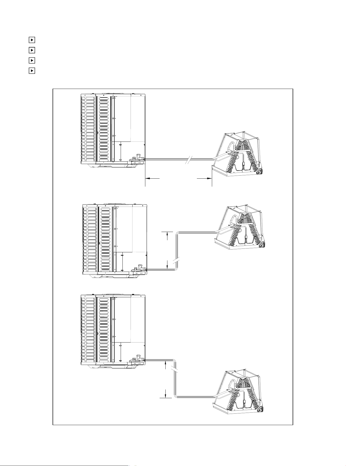
Figure 2.2
Maximum equivalent length of pipeline = 130 feet.
Maximum vertical equivalent length = 60 feet.
Use only the pipe diameters shown in Table 2.2.
If the suction line exceeds 60 feet, do not use a larger suction line than recommended.
Standard Lineset
Lineset 130' Max
Line Length
60' Max
Line Lift
60' Max
Line Lift
01 02 03 04
06
06 07 08 09 10 11 12 13 14 15 16 17 18 19
20 21 22 23 24 25 26 27 28 29 30 31 32 33 34 35 36
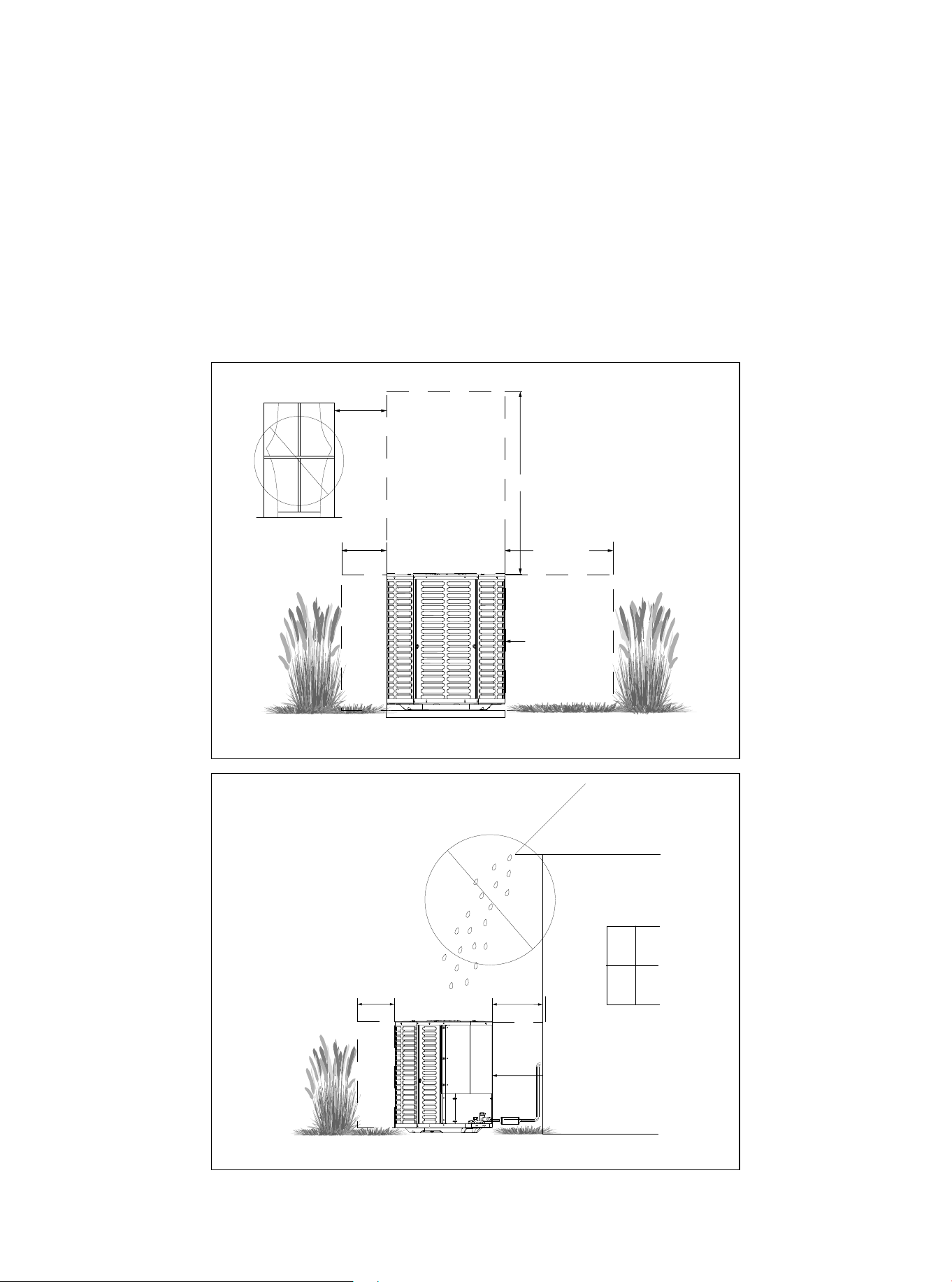
2.3 Position Restriction
Figure 2.3
Figure 2.4
● Make sure that the discharge area (at least 60 inches above the top of the unit) is unrestricted.
● Don't place the outdoor unit near a bedroom, as the normal operating sound may be disruptive.
● Position the equipment, leaving enough space for smooth airflow, wiring, refrigerant lines, and main-
tainability.
● There should be a minimum of 12 inches of clearance around the unit. However, there should be at
least 24 inches of clearance on the side with the access panel.
● Keep a distance of 24 inches between adjacent units.
● Place the unit in a place where water, snow, or ice cannot fall directly on the device from the roof or
overhangs.
● See figures 2.3 and 2.4.
Avoid Installations
Near Bedrooms
Min.12″ to
Shrubbery
Min.60″ Unrestricted
Min.24″
Unrestricted
Access Panel
Min.12″ to
Shrubbery
Min.24″ to
Shrubbery
Access Panel
01 02 03 04 05
07
07 08 09 10 11 12 13 14 15 16 17 18 19
20 21 22 23 24 25 26 27 28 29 30 31 32 33 34 35 36
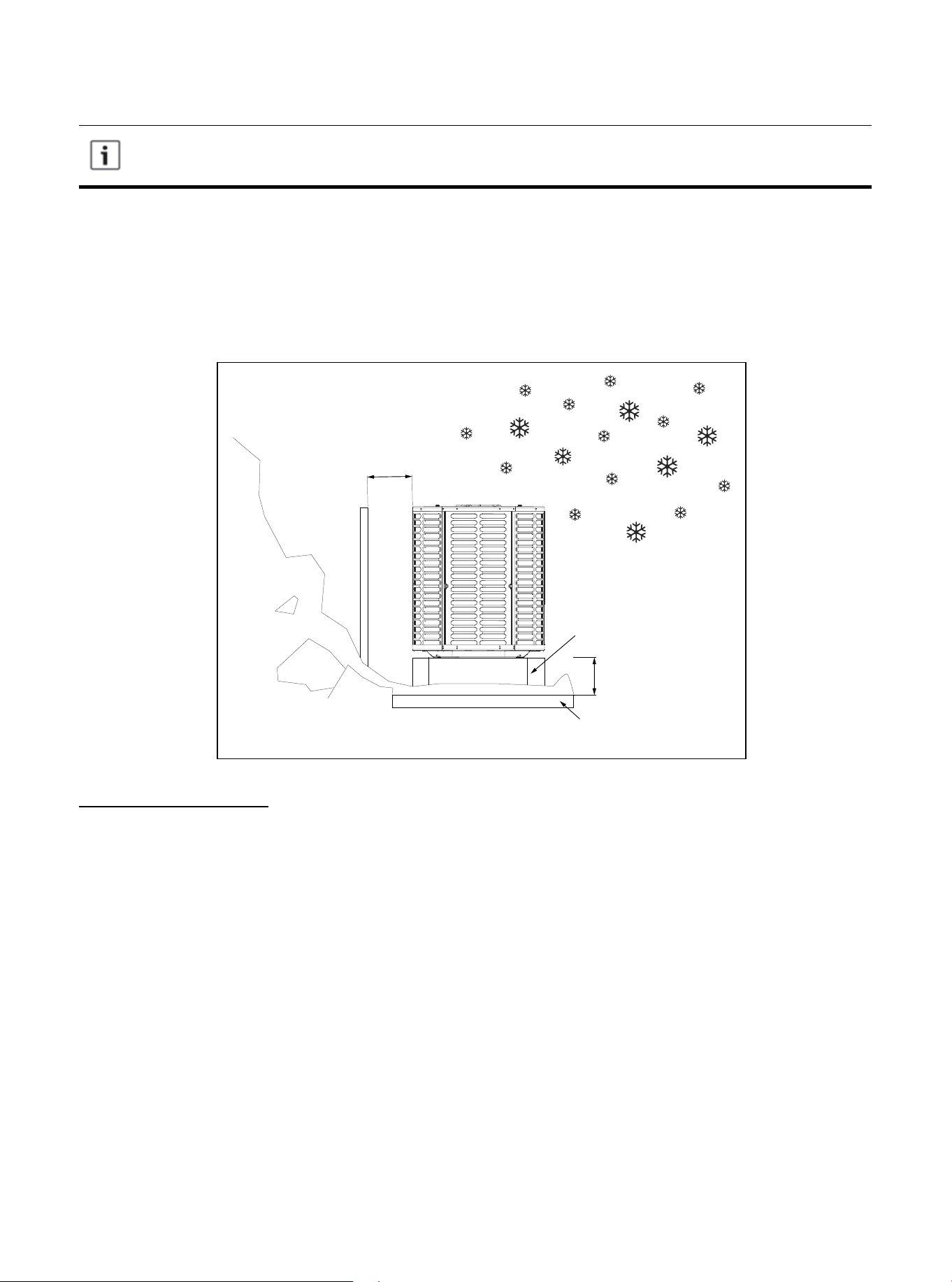
Figure 2.5
Precautions must be taken for units installed in areas with snow and long-term
temperatures below freezing point.
● Depending on the local weather conditions, the unit should be raised between 3 and 12 inches. This
extra height will allow the snow and ice melted during the defrosting cycle to be discharged before re-
freezing. Make sure that the drain hole on the unit chassis is not blocked, otherwise it will hinder the
defrosting water discharge (Figure 2.5).
● If possible, avoid places that are prone to snow. If this is not feasible, a snow barrier should be
installed around the unit to prevent snow accumulation on the side of the unit.
Snow
barrier
Min.12″
Snow legs
3-12″ Elevation
Pad
Corrosive Environment
Exposure to a corrosive environment may shorten the service life of the unit, corrode metal parts, and/
or negatively affect the performance of unit. Corrosive elements include but are not limited to: sodium
chloride, sodium hydroxide, sodium sulfate, and other compounds commonly found in seawater,
sulfur, chlorine, fluorine, fertilizers, and various chemical pollutants from industrial/manufacturing
plants. If it is installed in an area that may be exposed to a corrosive environment, special attention
should be paid to the placement and maintenance of the unit.
● Lawn sprinklers/hoses/waste water should not be sprayed directly on the outer panel of the unit for
an extended period of time.
● In coastal areas: install the unit on a side facing away from the waterfront.
● Fences or shrubs can provide some shielding protection for the unit, but be sure to keep the
minimum device clearance.
● Clean the outdoor coil and any exposed external surfaces approximately every three months.
01 02 03 04 05 06
08
08 09 10 11 12 13 14 15 16 17 18 19
20 21 22 23 24 25 26 27 28 29 30 31 32 33 34 35 36
These instructions are intended to provide a method of securing the system to the cement
slab as a anchoring procedure in windy areas. Check the local regulations of tie-down
methods and protocols.
4.1 Support Pad Installation
When installing the unit on a support pad (such as a concrete slab), please consider the following:
● All sides of the pad must be at least 1-2 inches larger than the unit.
● The pad must be separated from any structure.
● The pad must be level.
● The pad must be high enough above the ground for drainage.
● The location of the pad must comply with national, state and local regulations.
4. Unit Settings
Figure 3.1
3.1 Prepare the Unit for Installation
● Check for damage to the unit and report any damage to the carrier immediately. (Figure 3.1).
● The filler can be used to ensure that the refrigerant charge is maintained during shipment.
3. Unit Installation Preparation
01 02 03 04 05 06 07
09
09 10 11 12 13 14 15 16 17 18 19
20 21 22 23 24 25 26 27 28 29 30 31 32 33 34 35 36
Model
18K/24K/30K/36K/42K
48K/60K
Table 5.1
5.2 Length of Required Refrigerant Pipeline
Determine the required pipeline length (Figure 5.1). Please refer to Section 2.2.
5.1 Connecting Dimensions of Refrigerant Lines and Service Valves
5. Precautions for Refrigerant Pipeline
Figure 4.1
Figure 5.1
Suction line Liquid line
Suction line
connection
Liquid line
connection
The dimensions are in inches.
3/4 3/8 3/4 3/8
7/8 3/8 7/8 3/8
Line Length
01 02 03 04 05 06 07 08
10
10 11 12 13 14 15 16 17 18 19
20 21 22 23 24 25 26 27 28 29 30 31 32 33 34 35 36
The manufacturer recommends that only approved matching indoor and outdoor systems
be installed. All split systems are certificated by AHRI, and the indoor unit is equipped with
piston or TXV. The model of piston and TXV is selected by the manufacturer, please do
not change by yourself. The benefits of installing an approved indoor and outdoor split
system are maximum efficiency, best performance, and best overall system reliability.
Note: Mild to Moderate Burns
● If using existing refrigerant lines, make sure that all joints are brazed, not soldered.
5.4 Reusing the Existing Refrigerant Lines
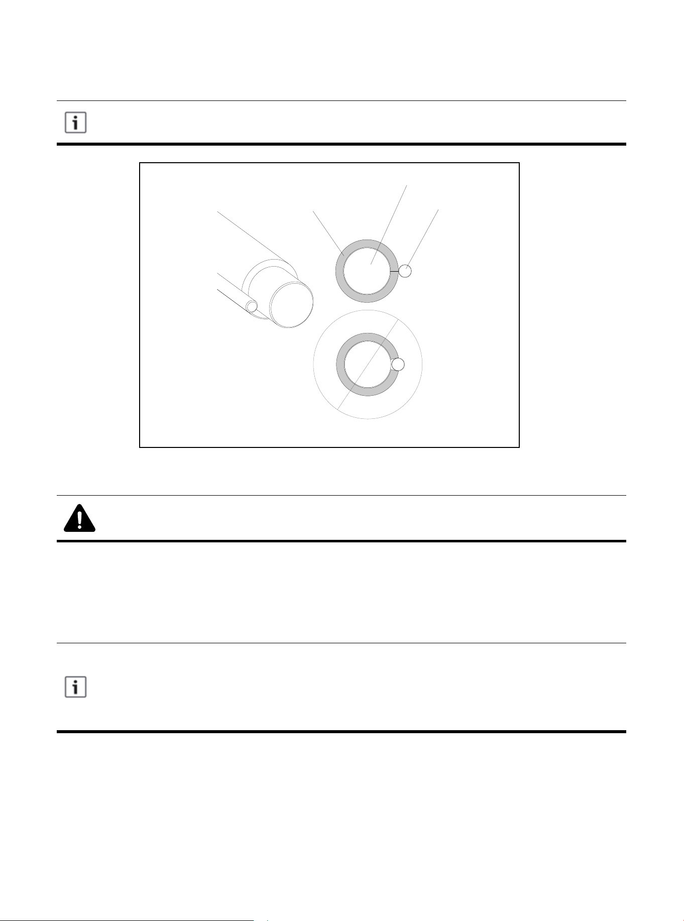
Figure 5.2
Liquid Line
Suction Line
Insulation
The following precautions should be taken for the retrofit application that will use the existing refrigerant
pipeline:
● Make sure the refrigerant line size is correct. Refer to Section 2.2 and Table 2.2.
● Make sure the refrigerant line is free of leakage, acid, and oil.
The air pipe must always be insulated. Do not let the liquid pipeline and gas pipeline come
into direct contact (metal to metal).
5.3 Refrigerant Pipe Insulation
01 02 03 04 05 06 07 08 09
11
11 12 13 14 15 16 17 18 19
20 21 22 23 24 25 26 27 28 29 30 31 32 33 34 35 36
6.1 Preventive Measure
6. Refrigerant Pipeline Routing
Take preventive measures to prevent noise generated by vibration transmission of refrigerant
pipeline in building structure. For example:
● When the refrigerant pipeline must be fixed on floor joists or other frames in the structure,
use isolated hangers.
● When the refrigerant pipeline runs in the column space or closed ceiling, the isolation
hanger should also be used.
● When refrigerant lines pass through walls or window sills, they should be insulated and
isolated.
● Isolate the pipeline from all piping systems.
● Try to reduce the number of 90º laps.
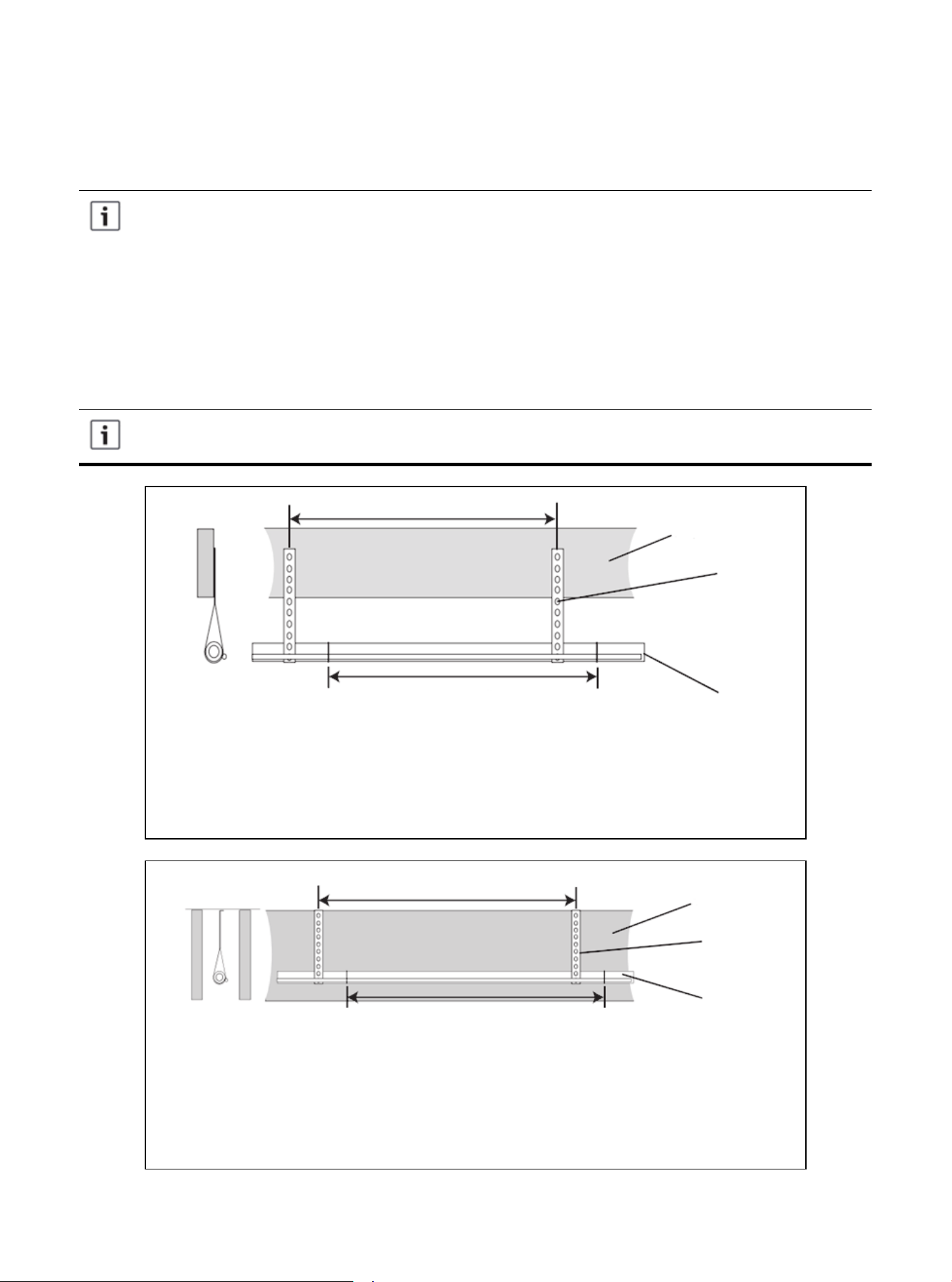
Comply with national, state, and local regulations when isolating the wire group from
joists, rafters, walls, or other structural elements.
Use isolators to secure the air pipes on the beams every 8 feet. Every 8 feet, tape,
wire or other suitable methods are used to fix the liquid line directly to the suction
line.
Isolated from beam/rafter
Figure 6.1
Use isolators to secure the suction line every 8 feet. Every 8 feet, attach the liquid
line directly to the suction line with tape, wire or other suitable methods.
Isolation on the wall
Figure 6.2
Up to 8 feet
Up to 8 feet
Side view
Beam/rafter
Sound arrester
Line set
Up to 8 feet
Up to 8 feet
Side view
Wall
Sound arrester
Line set
01 02 03 04 05 06 07 08 09 10
12
12 13 14 15 16 17 18 19
20 21 22 23 24 25 26 27 28 29 30 31 32 33 34 35 36
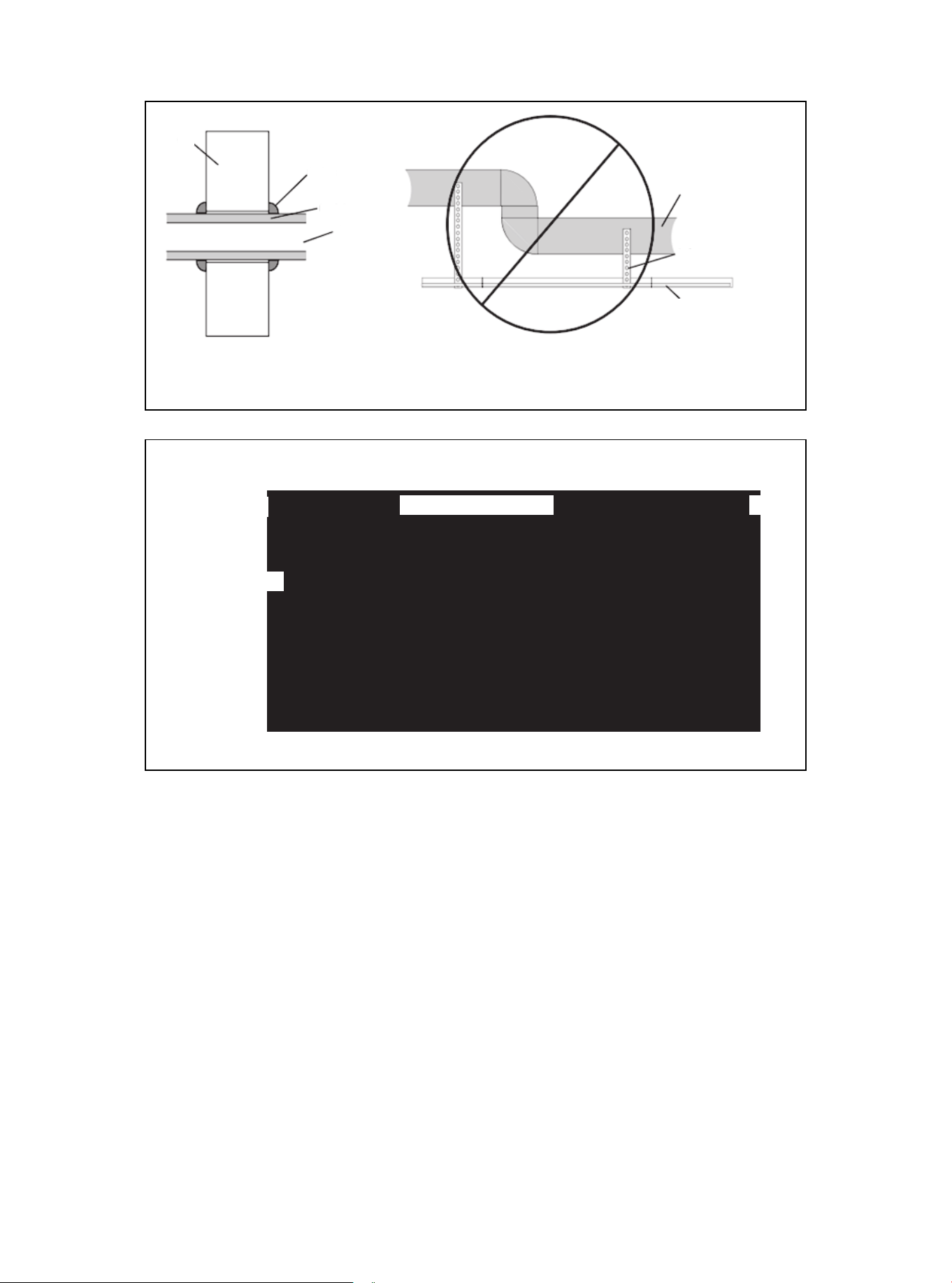
Figure 6.4
To indoor coil
Liquid line
PVC conduit
Insulated suction line
To outdoor unit
Cap
Figure 6.3
Wall
Sealant
Insulate
Suction line
Tubing
Sound arrester
Line set
Wall isolation
Do not hang the pipeline on the duct work.
01 02 03 04 05 06 07 08 09 10 11
13
13 14 15 16 17 18 19
20 21 22 23 24 25 26 27 28 29 30 31 32 33 34 35 36
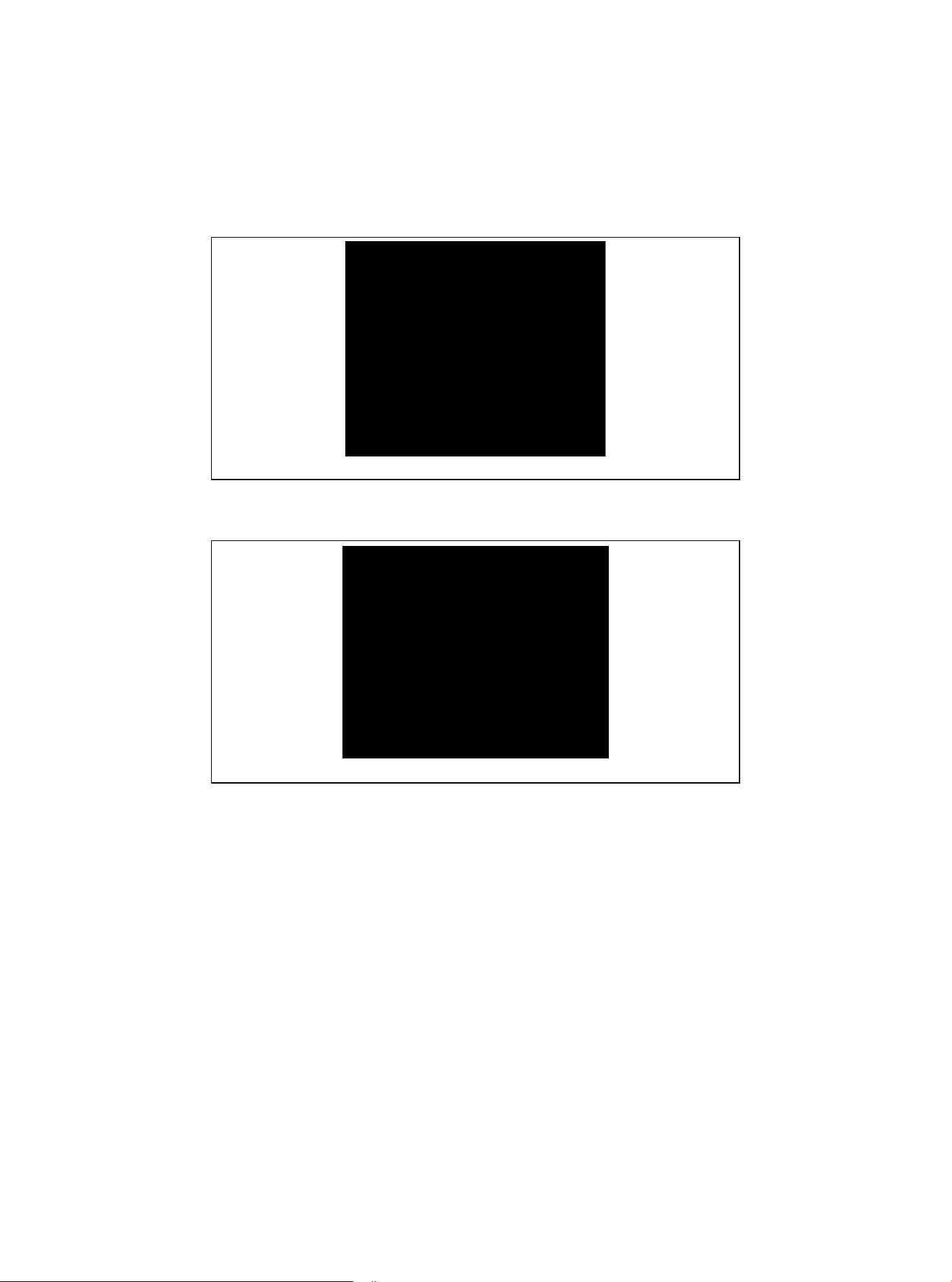
Figure 7.2
2. Remove the pressure taps from the two service valves.
7.1 Brazing Refrigerant Pipeline
7. Refrigerant Pipeline Brazing
Figure 7.1
1. Remove the cover or plug. Use the deburring tool to deburr the pipe end. Clean the inner and outer
surfaces of the pipeline with emery cloth.
01 02 03 04 05 06 07 08 09 10 11 12
14
14 15 16 17 18 19
20 21 22 23 24 25 26 27 28 29 30 31 32 33 34 35 36
All units are recommended to have bidirectional drying filters installed. Braze the drying
filter to the liquid pipe, taking care not to push the refrigerant pipe too hard through the
stopper in the drying filter (this may damage the dryer).
Before stopping the dry nitrogen purge, please remove the wet rag.
Figure 7.4
4. Wrap the valve body with a wet rag to avoid thermal damage, and continue the dry nitrogen purging
(Figure 16).
Braze the refrigerant line to the service valve.
Braze the filter dryer to the liquid pipe.
Figure 7.5
5. After the service valve cools down, replace the pressure tap.
Continue the dry nitrogen purge. Don't take off the wet rag before all brazing is completed.
Packaging and shipment
of on-site installation
3-4 inches from the valve
Figure 7.3
3. Purge refrigerant lines and indoor coils with dry nitrogen.
This pipe must
have a thimble.
01 02 03 04 05 06 07 08 09 10 11 12 13
15
15 16 17 18 19
20 21 22 23 24 25 26 27 28 29 30 31 32 33 34 35 36
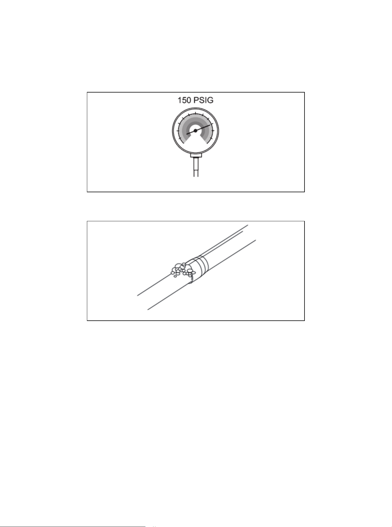
8.1 Check for Leaks
8. Refrigerant Pipeline Leakage Inspection
1. Use dry nitrogen to pressurize the refrigerant line and evaporator coil to 150 PSIG.
Figure 8.1
2. Use soapy water or foam at each brazing position to check for leaks.
Figure 8.2
01 02 03 04 05 06 07 08 09 10 11 12 13 14
16
16 17 18 19
20 21 22 23 24 25 26 27 28 29 30 31 32 33 34 35 36
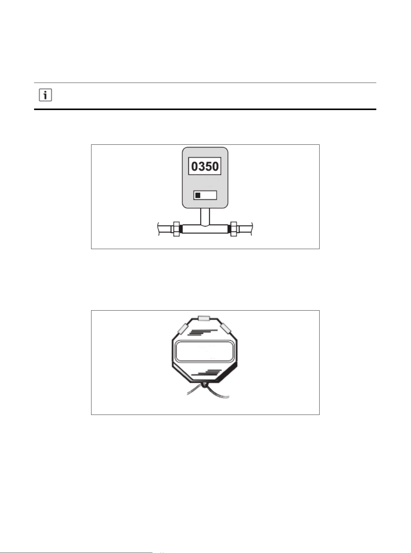
9.1 Emptying Refrigerant Pipeline and Indoor Coil
9. Emptying
Do not open the service valve until the leakage inspection and emptying of refrigerant
lines and indoor coils are completed.
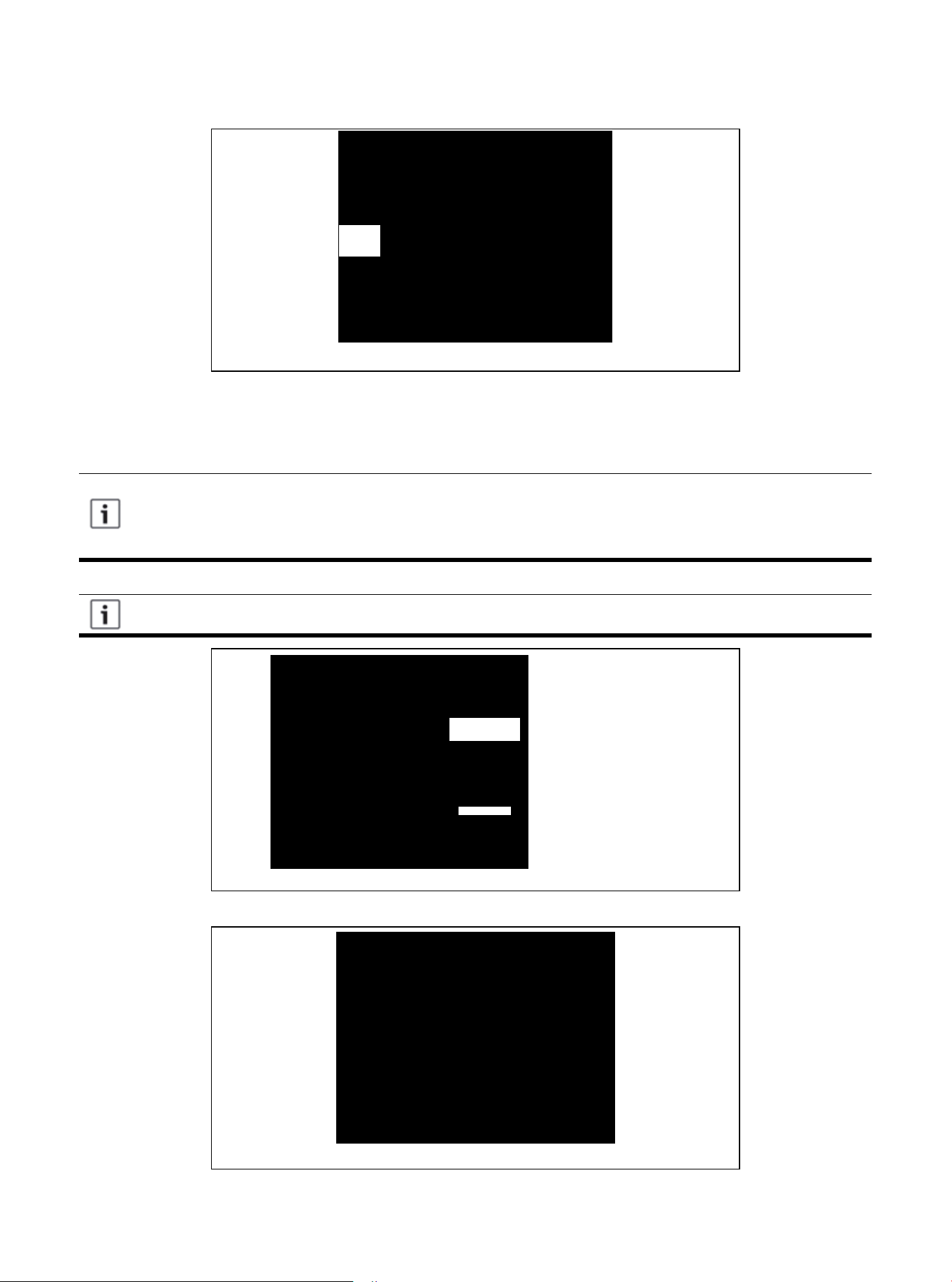
1. Evacuate until the micrometer reading is not higher than 350 micrometers, and then close the valve of
the vacuum pump.
2. Observe micrometer gauge. If the micrometer meter does not rise above 500 micrometers within one
(1) minute, the evacuation is completed.
After the evacuation, turn off the vacuum pump and micrometer, and close the valve on the manifold
instrument cluster.
Figure 9.1
Figure 9.2
01 02 03 04 05 06 07 08 09 10 11 12 13 14 15
17
17 18 19
20 21 22 23 24 25 26 27 28 29 30 31 32 33 34 35 36
Warning: Moderate to Severe Burns
● When opening the liquid side service valve, be extra careful. Turn counterclockwise until the
valve stem just touches the hem. No torque is required. Failure to observe this warning will
result in sudden release of system pressure, and may result in personal injury and/or proper-
ty damage.
10.1 Open the Service Valve
10. Service Valve
Before opening the service valve, the leakage inspection and emptying must be complet-
ed. The valve of copper welded pipe installation should be used for leakage inspection and
vacuum pumping. The use of a separate suction port in this process will lead to refrigerant
loss.
Before opening the liquid side service valve, the gas side service valve must be opened
first.
Figure 10.1
1. Remove the valve cover (Figure 10.1).
2. Insert the hex wrench into the valve stem completely and back out counterclockwise until the valve
stem just touches the bead (about five (5) turns).)
3. Replace the valve stem cap to prevent leakage. Tighten it with your fingers first, then, using a
crescent wrench, turn it for another 1/6 turn.
4. Repeat steps 1-3 for the liquid side service valve.
Cover
5/16 "Hexagon Wrench for Gas Measuring
and Repairing Valve
3/16 "Hexagon Wrench for
Liquid Side Service Valve
Device side of overhaul valve
Secure the rolled stem
Hexagon head valve system
01 02 03 04 05 06 07 08 09 10 11 12 13 14 15 16
18
18 19
20 21 22 23 24 25 26 27 28 29 30 31 32 33 34 35 36
11.1 Low Voltage Connection Diagram
11. Electrical-Low Voltage
The dotted line in the following thermostat wiring diagram indicates optional wiring (wiring
for passive dehumidification and/or electric heating). For the wiring of the thermostat,
please refer to the user manual of the thermostat.
Terminal B will be connected with the thermostat (O/B) wiring. The reversing valve is
energized during heating.
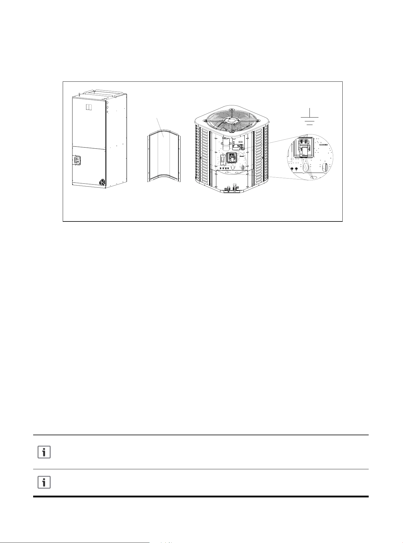
Figure 11.1 Connection of Low Voltage Device
11.2 Wiring Diagram of Thermostat
● Ensure that the power supply is consistent with the nameplate of the unit.
● The power connection and grounding of the unit must comply with local regulations.
● Low-voltage wiring is the smallest conductor of NO. 22AWG.
● "-----"On-site installation of electrical auxiliary thermal connection
● Single-stage electric auxiliary heating supported by 2H thermostat.
● Two-stage electric auxiliary heating supported by 3H thermostat.
● W1: The first stage of electric auxiliary heating installed in the indoor unit.
● W2: The second stage of electric auxiliary heating installed in the indoor unit.
● The W signal of the outdoor unit is connected to the electric auxiliary heating or the first-stage electric
auxiliary heat.
● The reference figure shows the selection of the low voltage wire hole of the 60K model, and the
selection of the wire hole of other models should be made according to the national, state, and local
regulations.
● The wires at the high and low voltage sides need to use different wire holes.
Control Board
Access Panel
01 02 03 04 05 06 07 08 09 10 11 12 13 14 15 16 17
19
19
20 21 22 23 24 25 26 27 28 29 30 31 32 33 34 35 36
NOTE: The reference figure shows the selection of the low voltage wire hole of the 60k model, and the
selection of the wire hole of other models should be made according to the national, state, and local
regulations.
The wires at the high and low voltage sides need to use different wire holes.
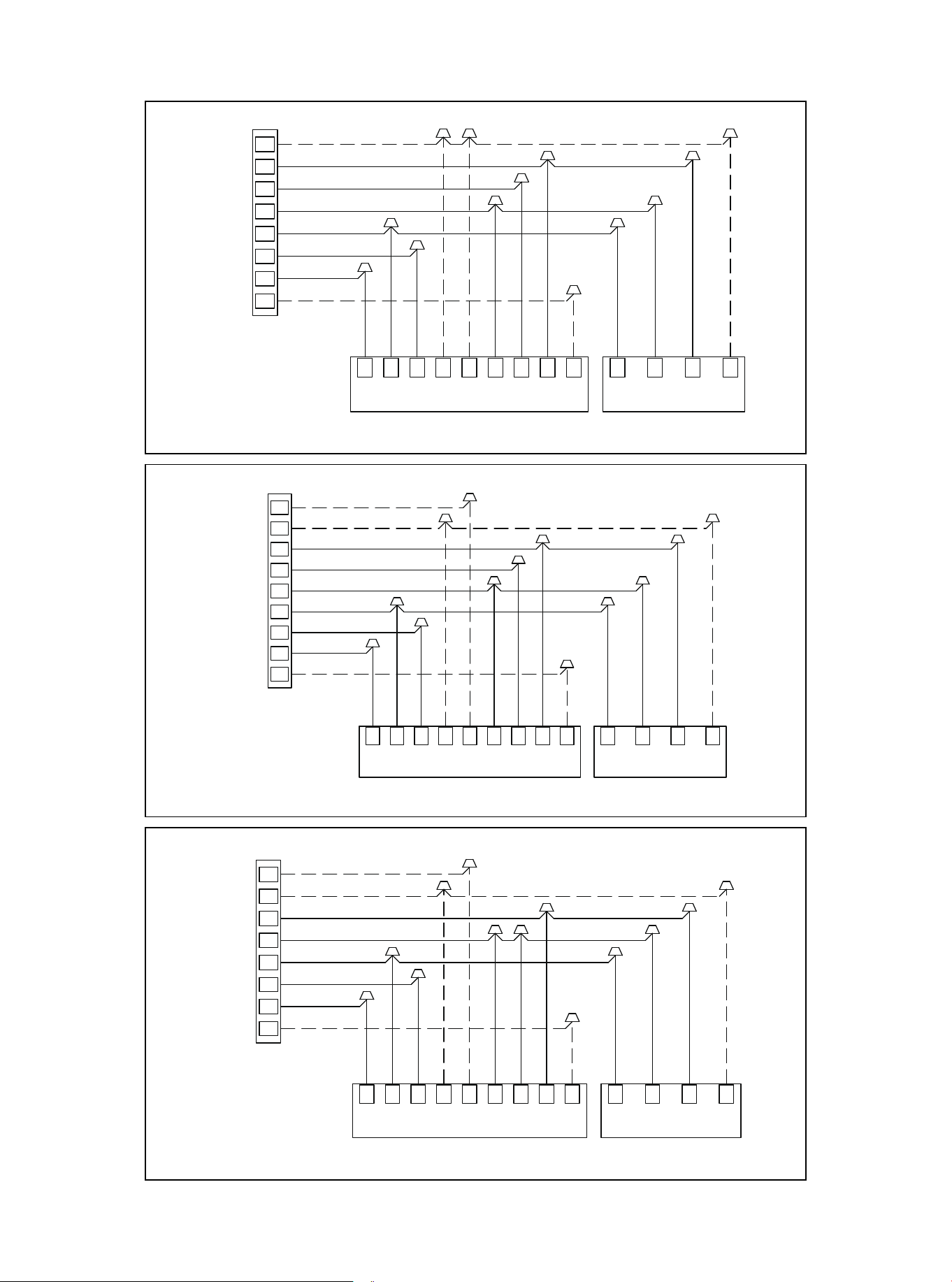
Figure 11.2 Control Wiring For HP Systems
Figure 11.3 Control Wiring For HP Systems
Figure 11.4 Control Wiring For HP Systems
01 02 03 04 05 06 07 08 09 10 11 12 13 14 15 16 17 18
20
20 21 22 23 24 25 26 27 28 29 30 31 32 33 34 35 36
W/E
THERMOSTAT
INDOOR UNIT
Y
R
G
C
H/DH
DHBC GR
Y1 Y2W1
W2
C Y B W
OUTDOOR UNIT
GRAY
BLUE
BROWN
GREEN
RED
YELLOW
PURPLE
WHITE
BLACK
BLACK
YELLOW
BLUE
PURPLE
Wiring for 4H and 2C thermostat
W2
Note: Any time the electric heat
elements are active,the indoor fan
will run in high stage.
Y2
O/B
W/E
THERMOSTAT
INDOOR UNIT
Y
R
G
C
O/B
H/DH
DHBC GR
Y1 Y2W1 W2
C Y B W
OUTDOOR UNIT
GRAY
BLUE
BROWN
GREEN
RED
YELLOW
PURPLE
WHITE
BLACK
BLACK
YELLOW
BLUE
PURPLE
Note: Because Y1 and Y2 are
jumped,the indoor fan will only run
in high stage.
Note: Any time the electric heat
elements are active,the indoor fan
will run in high stage.
Wiring for 3H and 1C thermostat
W2
Wiring for 3H and 2C thermostat
W/E
THERMOSTAT
INDOOR UNIT
Y
R
G
C
O/B
H/DH
DHBC GR
Y1 Y2W1 W2
C Y B W
OUTDOOR UNIT
GRAY
BLUE
BROWN
GREEN
RED
YELLOW
PURPLE
WHITE
BLACK
BLACK
YELLOW
BLUE
PURPLE
Note: Any time the electric heat
elements are active,the indoor fan
will run in high stage.
Y2
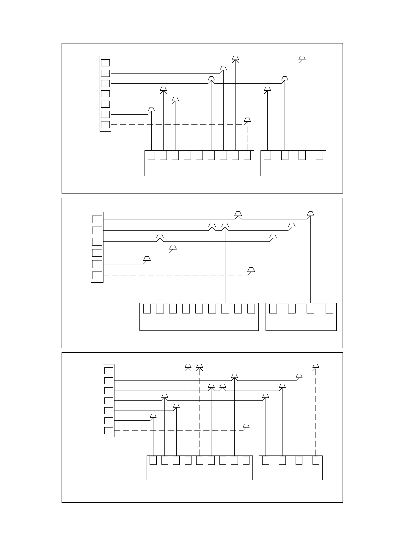
Figure 11.5 Control Wiring For HP Systems
Figure 11.6 Control Wiring For HP Systems
Figure 11.7 Control Wiring For HP Systems
01 02 03 04 05 06 07 08 09 10 11 12 13 14 15 16 17 18 19
21
21 22 23 24 25 26 27 28 29 30 31 32 33 34 35 36
THERMOSTAT
INDOOR UNIT
Y
R
G
C
O/B
H/DH
DHBC GR
Y1 Y2W1 W2
C Y B W
OUTDOOR UNIT
GRAY
BLUE
BROWN
GREEN
RED
YELLOW
PURPLE
BLACK
YELLOW
BLUE
Note: Because Y1 and Y2 are
jumped,the indoor fan will only run
in high stage.
Wiring for 1H and 1C thermostat
Y2
THERMOSTAT
INDOOR UNIT
Y
R
G
C
O/B
H/DH
DHBC GR
Y1 Y2W1 W2
C Y B W
OUTDOOR UNIT
GRAY
BLUE
BROWN
GREEN
RED
YELLOW
PURPLE
BLACK
YELLOW
BLUE
Wiring for 2H and 2C thermostat
Note: Any time the electric heat
elements are active,the indoor fan
will run in high stage.
W/E
THERMOSTAT
INDOOR UNIT
Y
R
G
C
O/B
H/DH
DHBC GR
Y1 Y2W1 W2
C Y B W
OUTDOOR UNIT
GRAY
BLUE
BROWN
GREEN
RED
YELLOW
PURPLE
WHITE
BLACK
BLACK
YELLOW
BLUE
PURPLE
Note: Because Y1 and Y2 are
jumped,the indoor fan will only run
in high stage.
Note: W1 and W2 are jumped,so
Electric Heat will only function in
high stage.
Wiring for 2H and 1C thermostat
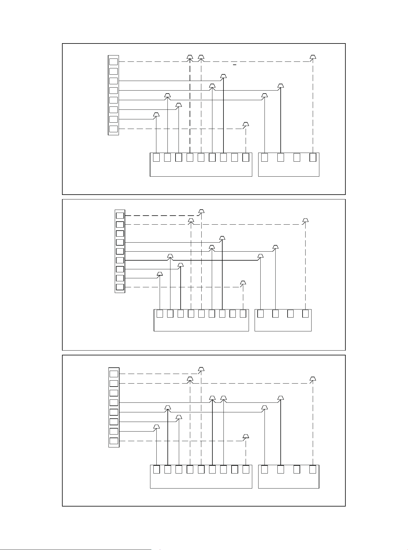
Figure 11.8 Control Wiring For AC Systems
Figure 11.9 Control Wiring For AC Systems
Figure 11.10 Control Wiring For AC Systems
01 02 03 04 05 06 07 08 09 10 11 12 13 14 15 16 17 18 19
20
22
22 23 24 25 26 27 28 29 30 31 32 33 34 35 36
W/E
THERMOSTAT
INDOOR UNIT
Y
R
G
C
O/B
H/DH
DHBC GR
Y1 Y2W1 W2
C Y B W
OUTDOOR UNIT
GRAY
BROWN
GREEN
RED
YELLOW
PURPLE
WHITE
BLACK
BLACK
YELLOW
PURPLE
Note: Because Y1 and Y2 are
jumped,the indoor fan will only run
in high stage.
Note: Any time the electric heat
elements are active,the indoor fan
will run in high stage.
Wiring for 3H and 1C thermostat
W2
Wiring for 3H and 2C thermostat
W/E
THERMOSTAT
INDOOR UNIT
Y
R
G
C
O/B
H/DH
DHBC GR
Y1 Y2W1 W2
C Y B W
OUTDOOR UNIT
GRAY
BROWN
GREEN
RED
YELLOW
PURPLE
WHITE
BLACK
BLACK
YELLOW
PURPLE
Note: Any time the electric heat
elements are active,the indoor fan
will run in high stage.
Y2
W/E
THERMOSTAT
INDOOR UNIT
Y
R
G
C
H/DH
DHBC GR
Y1 Y2W1
W2
C Y B W
OUTDOOR UNIT
GRAY
BROWN
GREEN
RED
YELLOW
PURPLE
WHITE
BLACK
BLACK
YELLOW
PURPLE
Wiring for 4H and 2C thermostat
W2
Note: Any time the electric heat
elements are active,the indoor fan
will run in high stage.
Y2
O/B
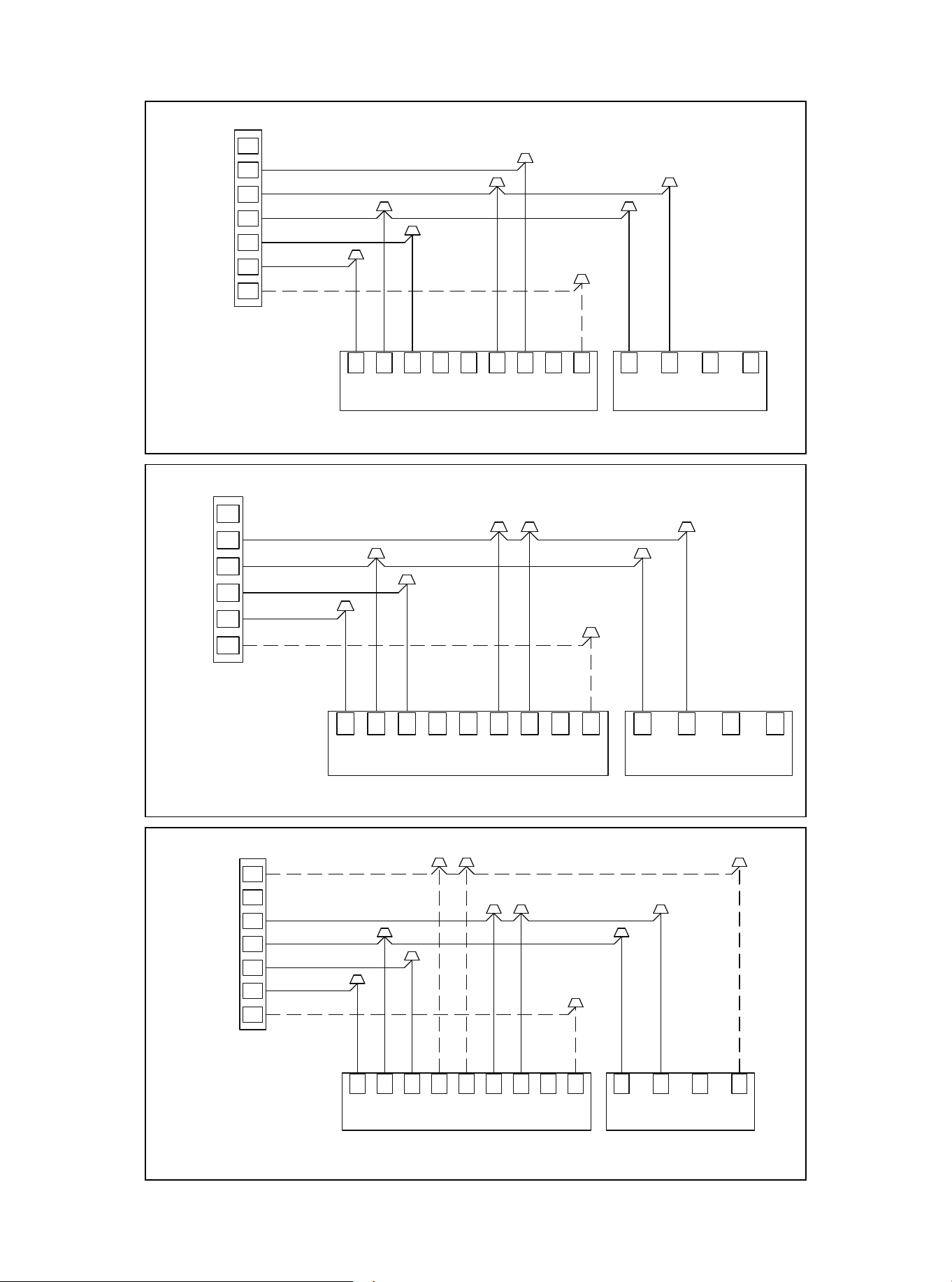
Figure 11.11 Control Wiring For AC Systems
Figure 11.12 Control Wiring For AC Systems
Figure 11.13 Control Wiring For AC Systems
01 02 03 04 05 06 07 08 09 10 11 12 13 14 15 16 17 18 19
20 21
23
23 24 25 26 27 28 29 30 31 32 33 34 35 36
Y2
THERMOSTAT
INDOOR UNIT
Y
R
G
C
O/B
H/DH
DHBC GR
Y1 Y2W1 W2
C Y B W
OUTDOOR UNIT
GRAY
BROWN
GREEN
RED
YELLOW
PURPLE
BLACK
YELLOW
Wiring for 2H and 2C thermostat
Note: Any time the electric heat
elements are active,the indoor fan
will run in high stage.
THERMOSTAT
INDOOR UNIT
Y
R
G
C
O/B
H/DH
DHBC GR
Y1 Y2W1 W2
C Y B W
OUTDOOR UNIT
GRAY
BROWN
GREEN
RED
YELLOW
PURPLE
BLACK
YELLOW
Note: Because Y1 and Y2 are
jumped,the indoor fan will only run
in high stage.
Wiring for 1H and 1C thermostat
W/E
THERMOSTAT
INDOOR UNIT
Y
R
G
C
O/B
H/DH
DHBC GR
Y1 Y2W1 W2
C Y B W
OUTDOOR UNIT
GRAY
BROWN
GREEN
RED
YELLOW
PURPLE
WHITE
BLACK
BLACK
YELLOW
PURPLE
Note: Because Y1 and Y2 are
jumped,the indoor fan will only run
in high stage.
Note: W1 and W2 are jumped,so
Electric Heat will only function in
high stage.
Wiring for 2H and 1C thermostat
Power supply wiring must comply with national, state and local regulations.
Warning: Live Electrical Parts
● During the installation, testing, maintenance and troubleshooting of this product, it may be
necessary to use live electrical parts. Failure to observe all electrical safety precautions
when exposed to live electrical parts may result in death or serious injury.
12.1 High Voltage Power Supply
12. Electrical-High Voltage
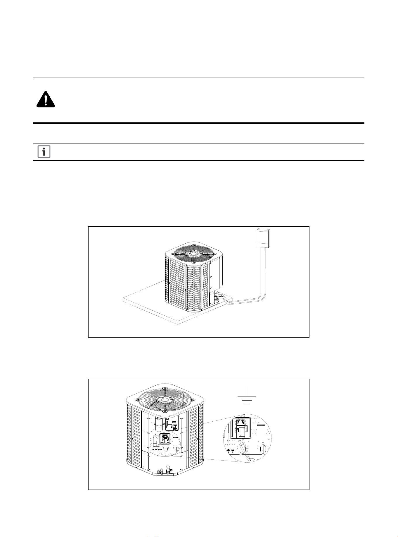
Figure 12.1
The high-voltage power supply must match the nameplate of the unit (208/230V, 1PH, 60Hz).
Follow the instructions of the unit wiring diagram located inside the access panel of the control box,
and refer to the wiring diagram in this manual.
12.2 High Voltage Isolating Switch
Install a separate disconnect switch on the outdoor unit.
High-voltage wiring must use flexible electrical conduit supplied on site.
12.3 High Voltage Grounding
Ground the outdoor unit according to the requirements of national, state, and local
regulations.
Figure 12.2
01 02 03 04 05 06 07 08 09 10 11 12 13 14 15 16 17 18 19
20 21 22
24
24 25 26 27 28 29 30 31 32 33 34 35 36
13.1 System Startup
1. Make sure that parts 7, 8, 9, 10, 11, and 12 have been completed.
2. Set the system thermostat to off.
13. Start
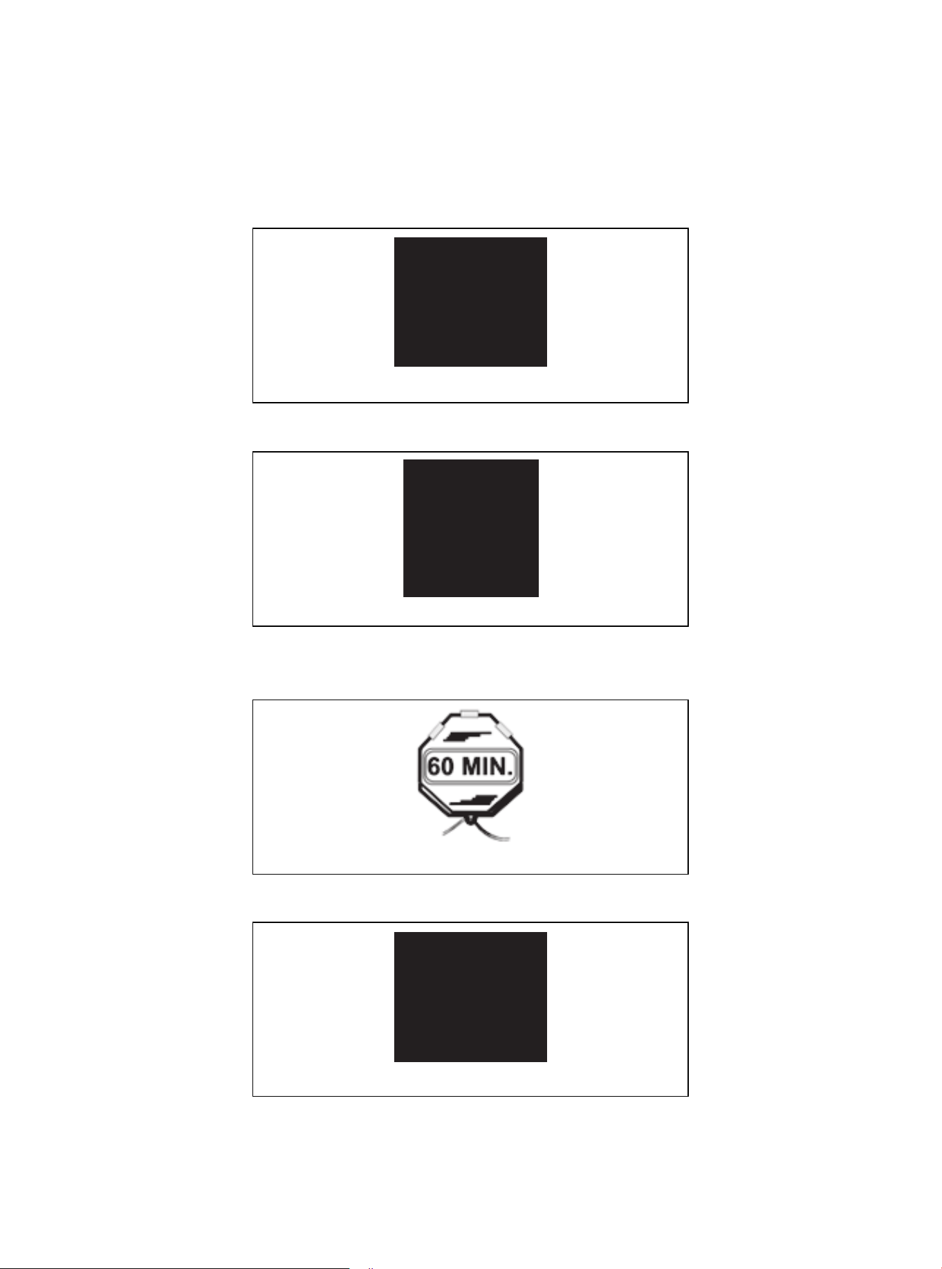
Figure 13.1
Figure 13.2
Figure 13.3
3. Turn on the disconnect switch and turn on the power to the indoor unit and outdoor unit.
4. When installing the unit for the first time, if the compressor crankshaft heater is used and the outdoor
ambient temperature is lower than 70°F, wait one (1) hour before starting the unit.
Figure 13.4
5. Set the system thermostat to ON.
01 02 03 04 05 06 07 08 09 10 11 12 13 14 15 16 17 18 19
20 21 22 23
25
25 26 27 28 29 30 31 32 33 34 35 36
14.1 Charging: Weighing Method
During the initial installation, or when the refrigerant quantity of the updated system is charged, the
weighing method is used. It must be used when there is no power supply at the site of the unit or the
operating condi-tions (indoor/outdoor temperature) are not within the range verified by Subcooling
charging method. All models have a charge factor of 0.6 oz / ft for refrigerant pipe length.
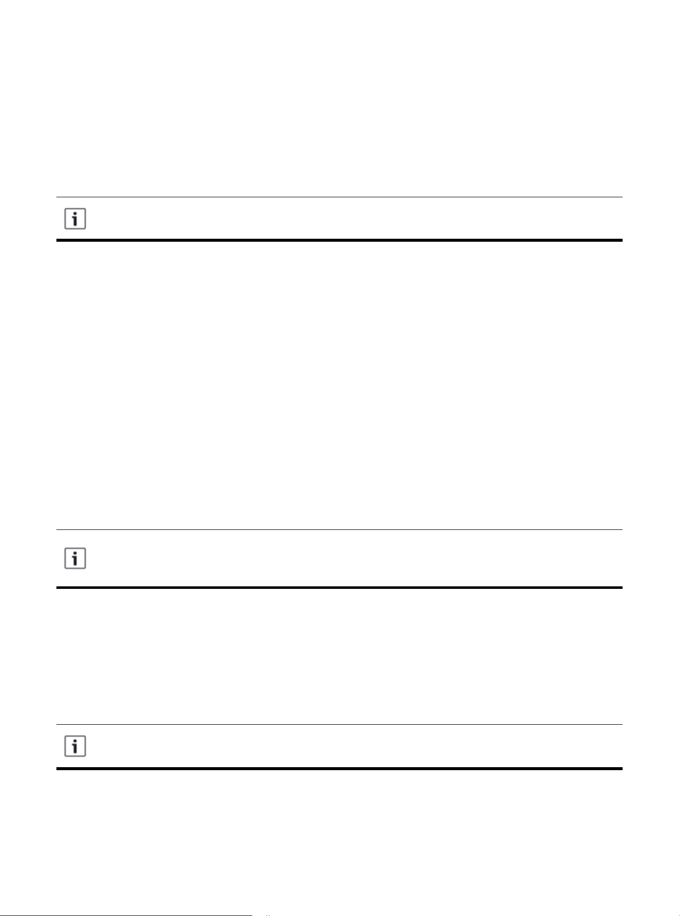
14.2 Subcooling Charging and Refrigerant Quantity Adjustment in Cooling
Mode
1. Check the outdoor ambient temperature.
Subcooling (cooling mode) is the only recommended charging method when the outdoor ambient
temperature is higher than 55°F.
For outdoor ambient temperature below 55°F, use the weighing charging method.
New installation-Calculate the charging amount of connecting pipes larger than 25 ft.
1. Total length of pipeline (ft) = _________(a)
2. Standard piping setup (ft) =25 (b)
3. (a) minus (b) = _________ (c)
4. Refrigerant multiplier = 0.6 oz/ft (d)
5. Additional refrigerant quantity (c*d) = _________(e)*
* If the line set is less than 25 feet, e=0
Closed system maintenance-calculate the total filling amount of the system.
1. Total length of pipeline (ft) = _________(a)
2. Standard piping setup (ft) =25 (b)
3. (a) minus (b) = _________ (c)
4. Refrigerant multiplier = 0.6 oz/ft (d)
5. Additional refrigerant quantity (c*d)= _________(e) *
6. Factory filling quantity (nameplate)= _________(f)
7. Total system charge (e +f) = ________
* If the line set is less than 25 feet, e =0
14. System Refrigerant Charging Regulation
For a 25-ft standard size interconnecting liquid pipe, the factory refrigerant charge of the
outdoor unit is sufficient.
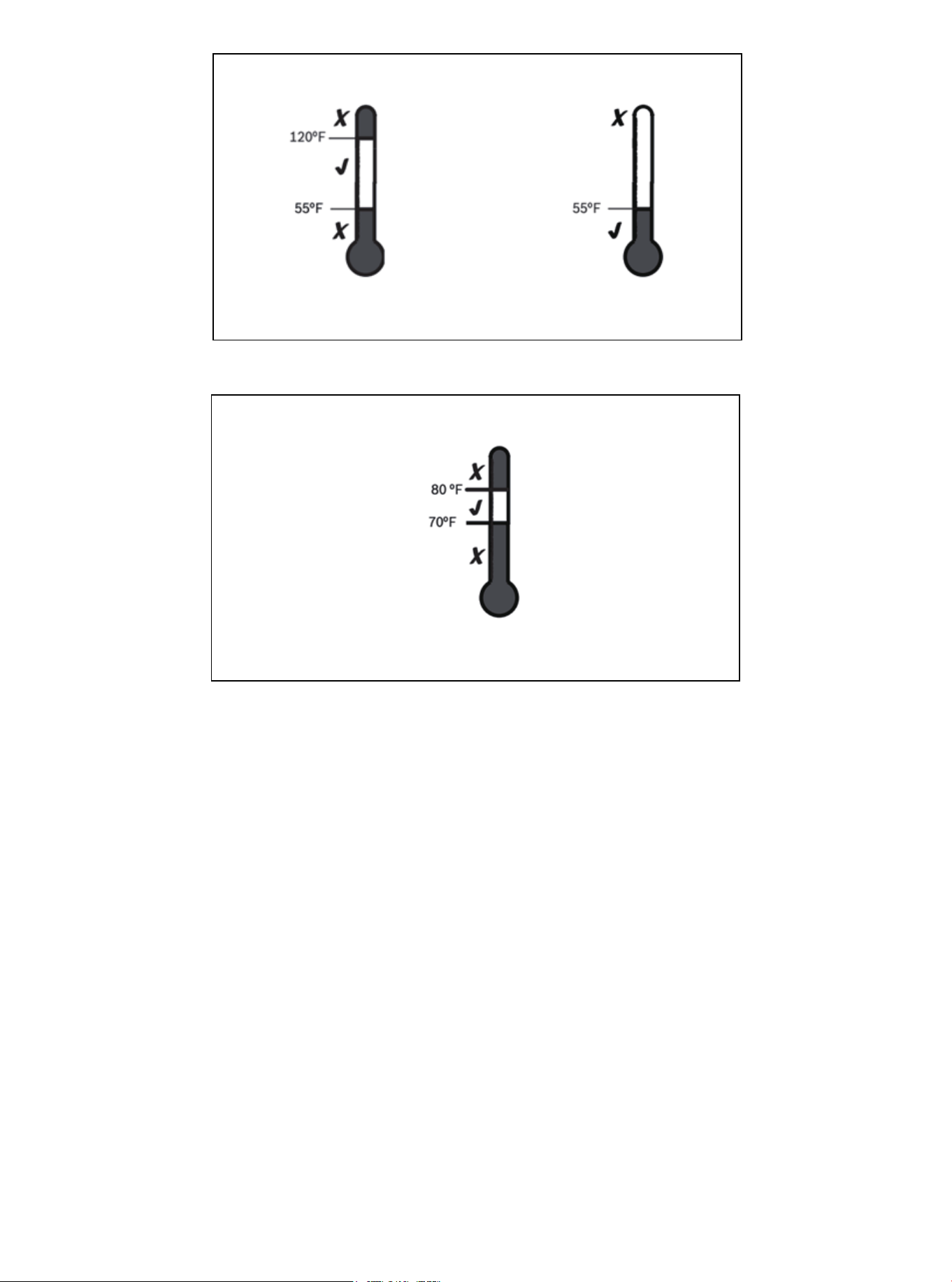
The only mode approved for verifying system charging is when the unit is in "forced cooling
mode". The outdoor temperature must be between 55°F and 120°F, and the indoor temperature
should be between 70°F and 80°F.
When the outdoor ambient temperature is higher than 55°F, be sure to return in spring or
summer, so as to accurately charge the system in cooling mode.
01 02 03 04 05 06 07 08 09 10 11 12 13 14 15 16 17 18 19
20 21 22 23 24
26
26 27 28 29 30 31 32 33 34 35 36
Outdoor temperature is
higher than 55°F.
Outdoor temperature
is below 55 °F.
Outdoor temperature 1 Outdoor temperature 2
Figure 14.1
Figure 14.2
For best results, the indoor temperature should be kept between 70°F and 80°F during installation.
Outdoor temperature is
higher than 55°F.
Indoor temperature
2. Make sure that parts 7, 8, 9, 10, 11, 12 and 13 have been completed.
01 02 03 04 05 06 07 08 09 10 11 12 13 14 15 16 17 18 19
20 21 22 23 24 25
27
27 28 29 30 31 32 33 34 35 36
15.1 Control Logic Description
● The system uses universal 24V control.
15.2 Sensors
● T3- Outdoor unit coil temperature (Table 15.3)
● T4- Ambient temperature (Table 15.3)
● T5- Compressor exhaust temperature (Table 15.4)
● TH-Compressor suction temperature (Table 15.3)
● HP- High pressure switch
● LP- Low pressure switch
15.3 Description of Defrosting
● Outdoor unit W terminal will output 24V signal during defrost mode.
● Unit will run defrost mode in the following conditions:
1) Unit run in heating mode
2) Compressor is running.
3) The defrost mode and cycle time is in relation to SW1-1 and SW1-2 dial switch
15. System Operation and Troubleshooting
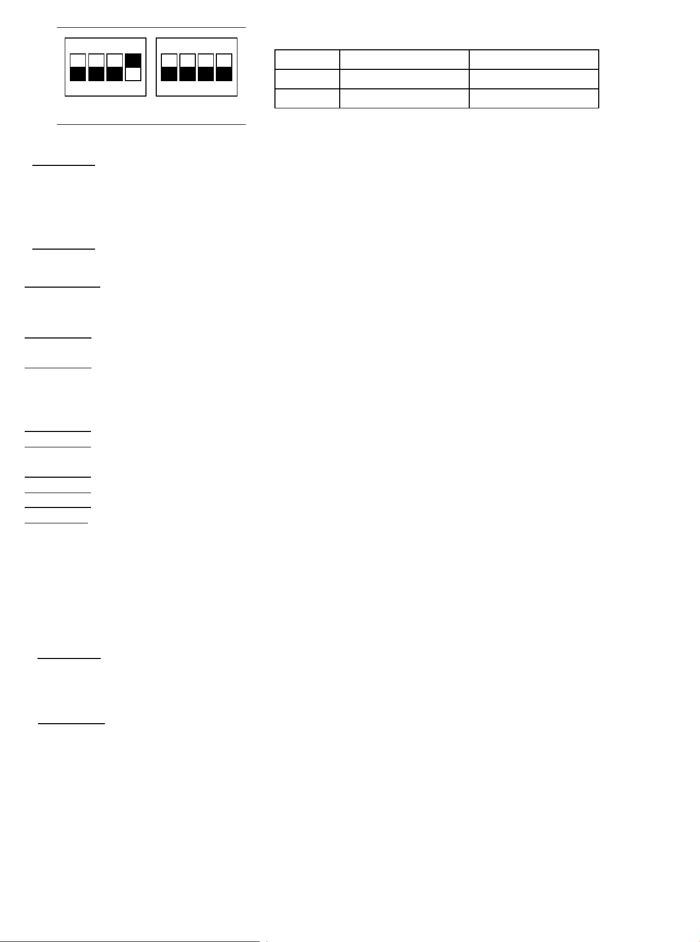
Dial switch SW1-1
OFF Defrost mode 1
ON Defrost mode 2
SW1-2
Cycle time: 60 min
Cycle time: 30 min
Table 15.1
Figure 15.1
ON KE
1 3 42
ON KE
1 3 42
① When SW1-1 is OFF, the unit will run defrost mode 1 when it meets any of the following conditions:
Condition 1: When compressor starts,
the unit will record minimum T3 which is named T30, and minimum
T4 which is named T40 during compressor runs 10-15mins.
When outdoor unit meets the following conditions, the unit will run defrost mode:
a) When T3<0, and compressor runs for 40mins;
b) Unit calculate ΔT4=T4-T40(If ΔT4≤2, unit will resultΔT4=0), and T3 + 2 < (T30+ΔT4) keep 30s.
Condition 2: When T3<0, and compressor run for 40mins, and T3<5°F (-15℃), unit will defrost.
② When SW1-1 is ON, unit will run defrost mode 1 when it meets any of the following conditions:
Condition 1:
a) SW1-2 is ON, and the compressor is running, when T3<5°F (-
1℃) and keep 30 mins, the unit will run defrost.
b) SW1-2 is OFF, and the compressor is running, when T3<5°F (-1℃) and keep 60 mins, the
unit will run defrost.
01 02 03 04 05 06 07 08 09 10 11 12 13 14 15 16 17 18 19
20 21 22 23 24 25 26
28
28 29 30 31 32 33 34 35 36
Condition 2: When the unit power is on, and compressor is starting for the first time, and T3<28.4°F (-2℃) , the unit
will run defrost.
Condition 3: When unit is on standby for 2 hours, and T3<28.4°F (-2℃) , unit will run defrost.
Quit defrost condition:
① When SW1-1 is OFF, unit will quit defrost when it meets any below condition.
Condition 1: Defrost time lasts
10 mins. per cycle.
Condition 2: T3≥ 50°F (10℃)
① When SW1-1 is ON, unit will quit defrost when it meets any below condition.
Condition 1: Defrost time lasts 10 mins.
per cycle.
Condition 2: T4≥28.4°F (-2℃) and T3≥77°F (25℃)
Condition 3: Compressor stops
Condition 4: T4<28.4°F (-2℃), T3≥77°F (25℃) and keep 60s.
15.4 Crankshaft Heater Control Function (Optional)
The crankshaft heater logic is below:
① Crankshaft heater ON condition:
When the unit meets any of the following conditions, the crankshaft heater will turn ON:
Condition 1
: Meet 3 of the following conditions at the
same time:
a) T5<73.4°F (23℃) or T5 sensor is abnormal.
b) Outdoor unit is in standby mode, and T4 was lower 50°F (10℃) before.
c) Outdoor unit stop time ≥4h(or 3.5h when unit power on first time).
Condition 2:
a) Outdoor unit power is
on, and T5<73.4°F (23℃)
;
b) Outdoor unit is in defrost mode, and T5<73.4°F (23℃)。
② Crankshaft heater OFF condition
T5≥82.4°F (28℃
)
and no T5 error
15.5 Four-way
Valve
Operating Condition
Four-way valve will power on in heating mode, and power off in cooling mode.
01 02 03 04 05 06 07 08 09 10 11 12 13 14 15 16 17 18 19
20 21 22 23 24 25 26 27
29
29 30 31 32 33 34 35 36
15.6 Anti-Freeze Protection: Effective Only in Cooling Mode
If the compressor suction temperature is less than 32°F, the compressor will be stopped. If the compressor
suction temperature is greater than 46.4°F, or the length of the shutdown has reached 6 minutes, the
compressor will start. (Minimum start interval of 5 minutes.)
15.7 Anti-High Temperature Protection: Effective Only in Heating Mode
High temperature protection will be effective in heat pump mode.
If the discharge temperature is over 179.6°F, and the fan motor is turned on over 3 minutes, then the
outdoor fan motor will be turned off. If the discharge temperature is less than 168.8°F, and the outdoor fan
motor is turned off for a maximum of 6 minutes, then the outdoor fan motor will be turned on again.
If the outdoor fan motor is turned off, and the discharge temperature is more than 221°F, and lasted for 2
minutes, then it's likely the system is severely lacking refrigerant. This will lead to unit shutdown.
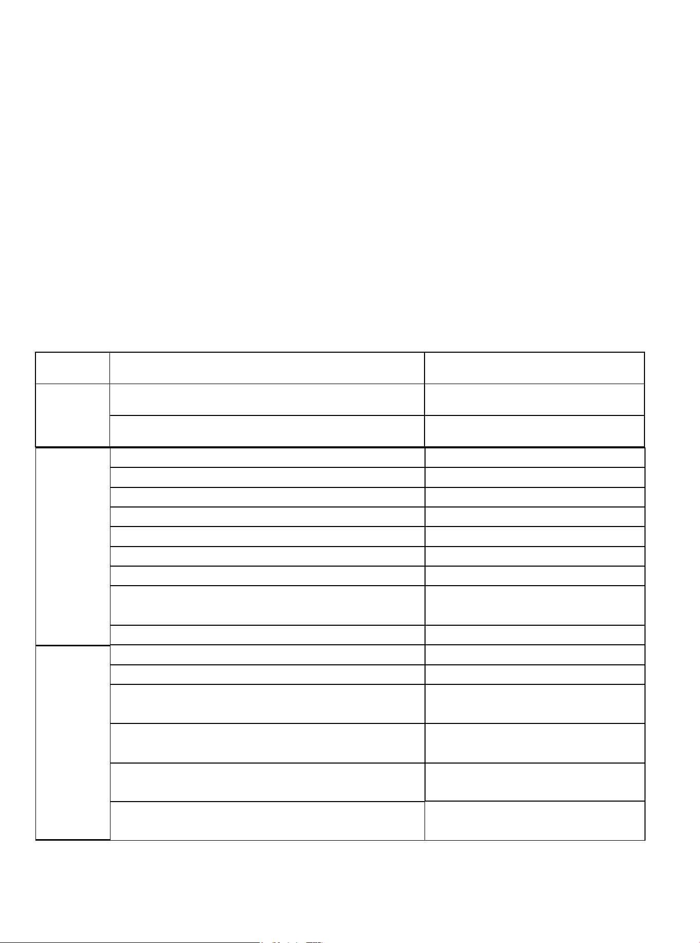
15.8 LED display function of the outdoor unit main PCB and fault table
Display
Content:
Content
Description
Display
Content:
T3 temperature sensor error
Yellow light flash 1 time for every 8s
T4 temperature sensor error Yellow light flash 2 time for every 8s
T5 temperature sensor error Yellow light flash 3 time for every 8s
Low pressure protection Yellow light flash 4 time for every 8s
High pressure protection Yellow light flash 5 time for every 8s
T3 high temperature protection Yellow light flash 6 time for every 8s
T5 high temperature protection Yellow light flash 7 time for every 8s
Low pressure protection occur 6 times within 60 mins. Yellow light flash 4 times for every 8s
High pressure protection occur 6 times within 60 mins. Yellow light flash 5 times for every 8s
T3 high temperature protection occur 6 times
within 60 mins.
Yellow light flash 6 times for every 8s
T5 high temperature protection occur 3 times
within 20 mins.
Yellow light flash 7 times for every 8s
Fan motor feedback error
Yellow light flash 8 times for every 8s
(Only for DC fan motor)
Normal
Display:
Yellow Light
OFF
Green light flash slow Unit standby
Green light ON Unit is running
Outdoor
unit error
and locked:
Green light
ON, Yellow
light flash.
Table 15.2
TH temperature sensor error
Yellow light flash 9 times for every 8s
Yellow light flash 8 times for every 8s
Yellow light flash 9 times for every 8s
Fan motor feedback error occur 3 times
within 20 minutes
Refrigerant leakage protection
1. W COMP R C terminal(24V)
2. W1 B Y terminal(
24V)
3. TH temperature sensor terminal
4. T3 temperature sensor terminal
5. T4 temperature sensor terminal
6. T5 temperature sensor terminal
7. Reserved
8. Low pressure switch terminal
9. High pressure switch terminal
10. TEST terminal
11. Dial switch
12. DC fan motor terminal
13. DEBUG terminal
14. Power input N terminal
15. Power input L terminal
16. Crankshaft heater terminal
17. Four-way valve terminal
Num
1
2
3
4
5
6
7
8
9
10
11
12
13
14
15
16
17
15.9 Outdoor Unit Main PCB Description
Outdoor Unit Main PCB
01 02 03 04 05 06 07 08 09 10 11 12 13 14 15 16 17 18 19
20 21 22 23 24 25 26 27 28
30
30 31 32 33 34 35 36
Figure 15.2
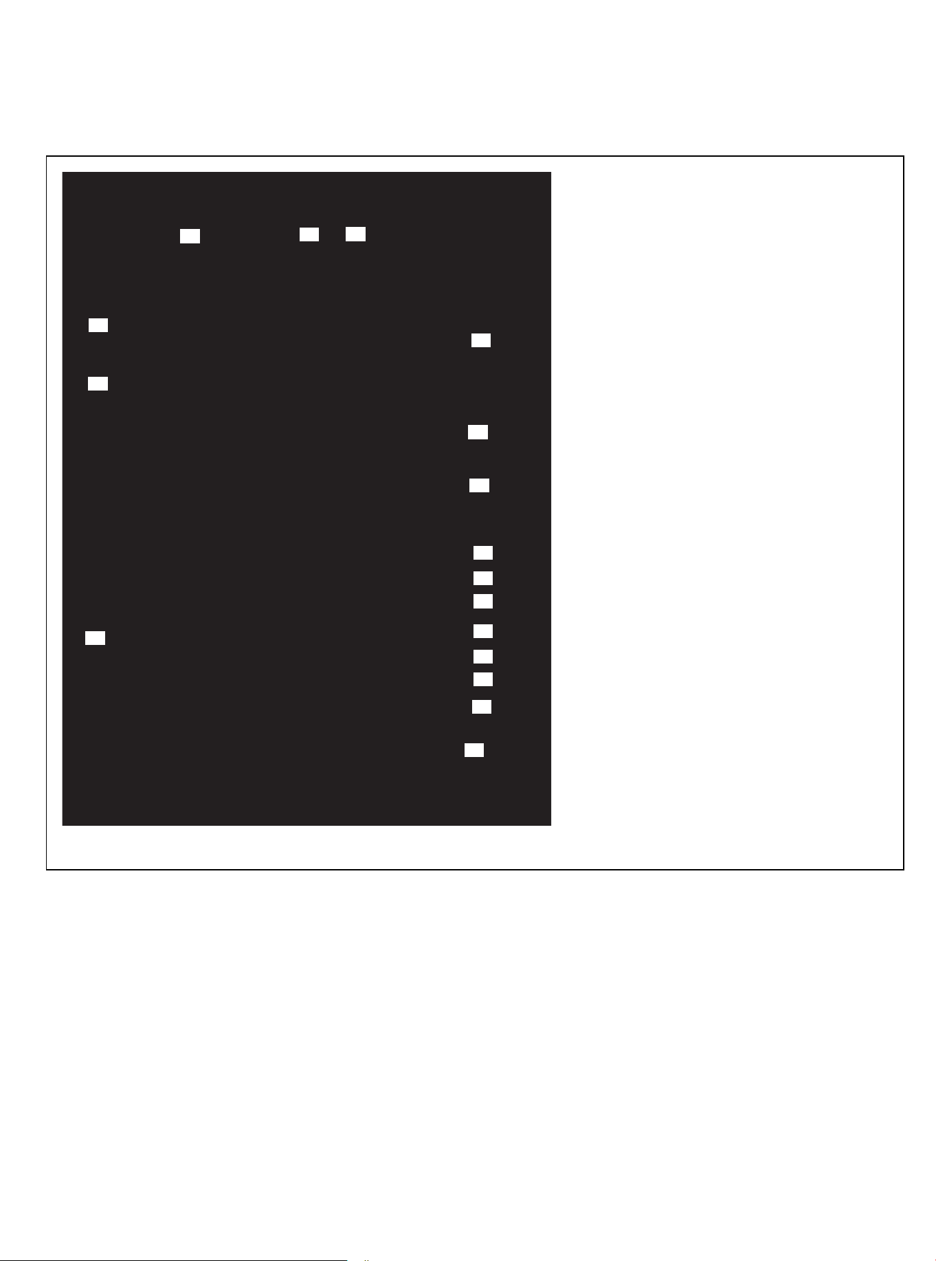
Functional Description
Condenser temp. sensor abnormal
Check the connection between
sensor and PCB
Well connected, then
replace the sensor or PCB
Check if the sensor is damaged? Replace it with a new sensor
Check PCB
Replace PCB
Sensor is open circuit?
Sensor is short circuit?
Component damaged?
Wet?
Error
Error
Error
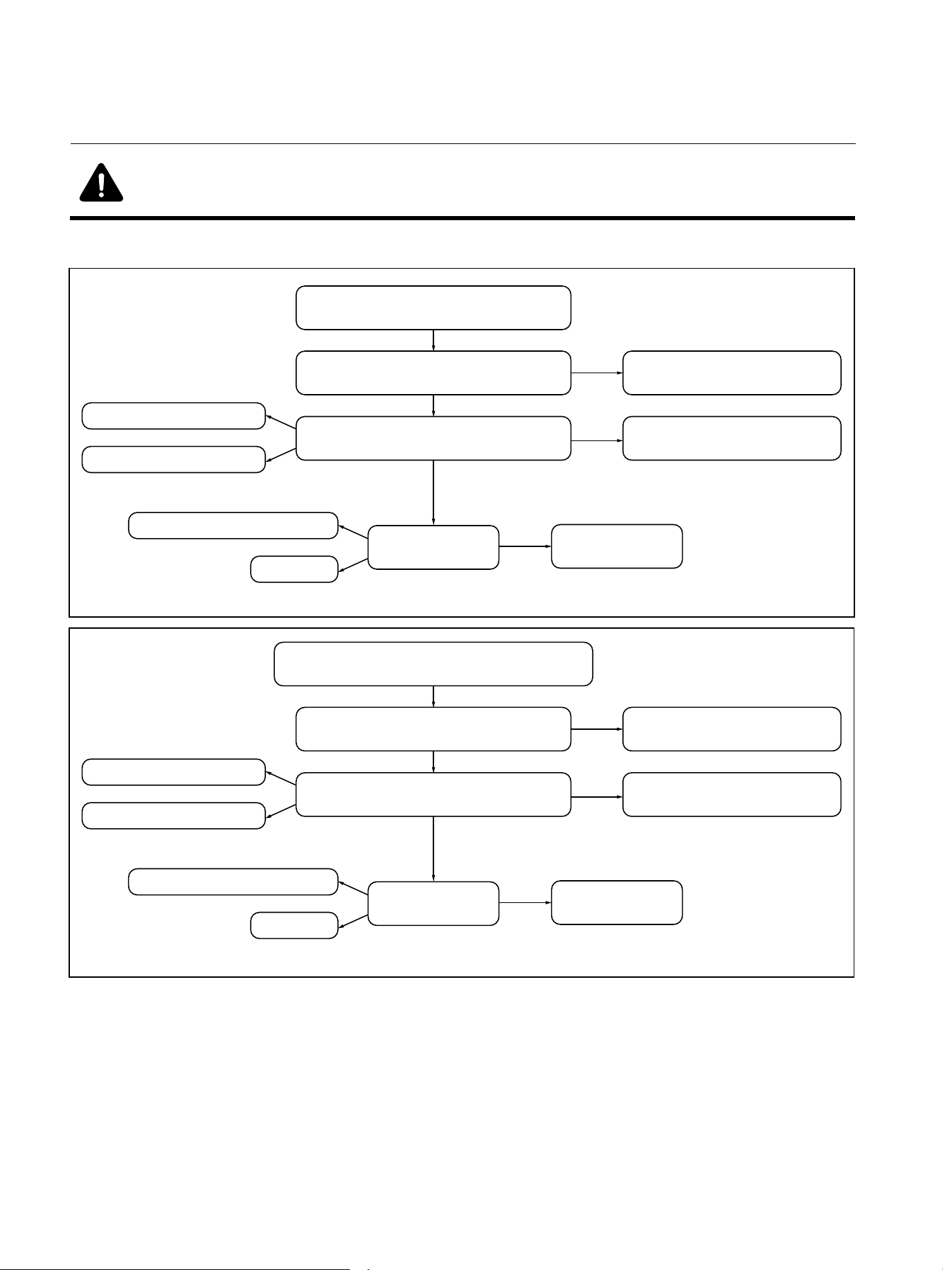
Figure 15.3 T3 Condenser Temperature sensor error
No
No
Outdoor ambient temp. sensor abnormal
Check the connection between
sensor and PCB
Well connected, then
replace the sensor or PCB
Check if the sensor is damaged? Replace it with a new sensor
Check PCB
Replace PCB
Sensor is open circuit?
Sensor is short circuit?
Component damaged?
Wet?
Error
Error
Error
Figure 15.4 T4 Outdoor Ambient Temperature sensor error
No
No
01 02 03 04 05 06 07 08 09 10 11 12 13 14 15 16 17 18 19
20 21 22 23 24 25 26 27 28 29
31
31 32 33 34 35 36
Warning: Dangerous Voltage
● When measuring the resistance, make sure that the power to the unit is turned off and wait
for 3 minutes before measuring.
15.10 Troubleshooting of Fault Codes
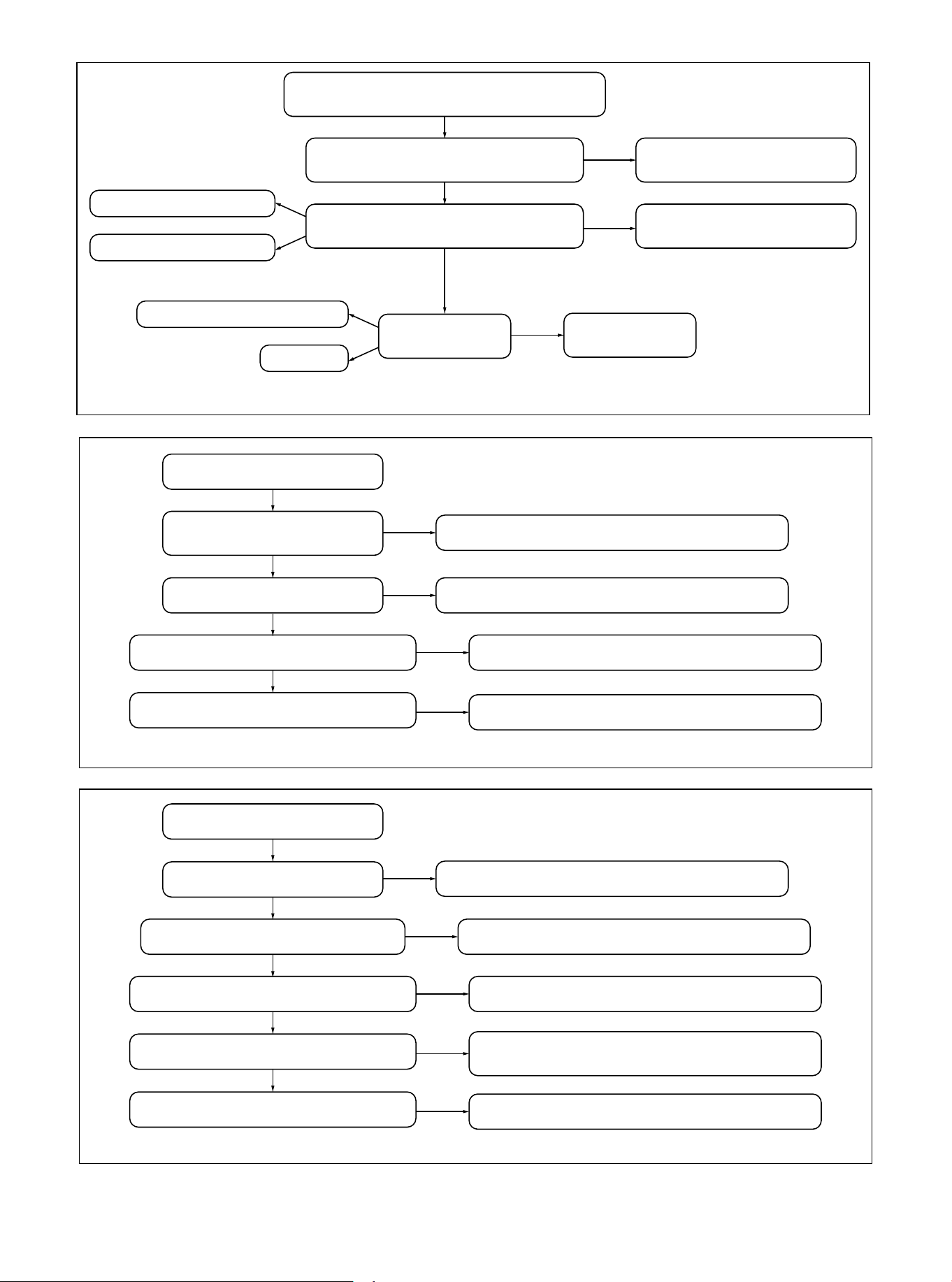
Low Pressure alarm
Lack of refrigerant
Check the gas side of the system
Heat exchanger is in poor condition
Replace PCB or low pressure switch
Check the PCB and
pressure switch
Error
Repair the leakage & charge refrigerant
Error
Remove the dirty and open the valve
Error
Repair the heat exchanger
Error
Figure 15.6 Low Pressure alarm
High Pressure alarm
Heat exchanger of outdoor is bad
Check the liquid side of the system
There is N2 or air in the system
Replace the switch and PCB
Check the switch and PCB
Error
Check and repair one by one
Error
Remove the dirty and open the valve
Error
Discharge the refrigerant & vacuum,
recharge the refrigerant
Error
Too much refrigerant in the system
Discharge some refrigerant
Error
Figure 15.7 High Pressure alarm
01 02 03 04 05 06 07 08 09 10 11 12 13 14 15 16 17 18 19
20 21 22 23 24 25 26 27 28 29 30
32
32 33 34 35 36
Discharge temp. sensor abnormal
Check the connection between
sensor and PCB
Well connected, then
replace the sensor or PCB
Check if the sensor is damaged? Replace it with a new sensor
Check PCB
Replace PCB
Sensor is open circuit?
Sensor is short circuit?
Component damaged?
Wet?
Error
Error
Error
Figure 15.5 T5 Discharge Temperature sensor error
No
No
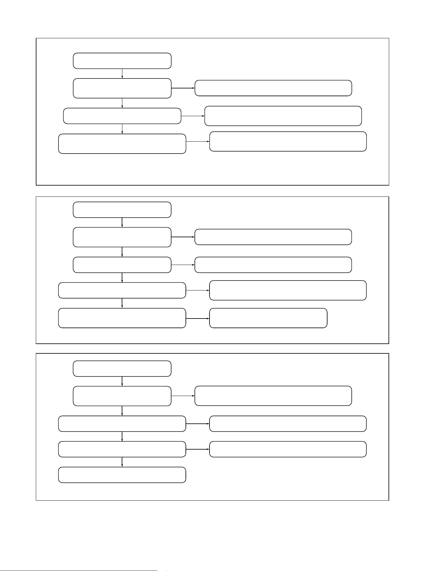
Fan motor feedback error
Check the DC fan driver board
Check the Fan8 port of main PCB
Replace the fan motor
It should be connect correctly
according to the wiring diagram
Check if the DC fan motor
wiring is correct
Error
Replace fan driver board
Error
Replace the main PCB
Error
Figure 15.10 Fan motor feedback error
Figure 15.9 T5 high temperature alarm
T5 high temp. alarm
Lack of refrigerant
There is N2 or air in the system
Power off and re-power on to
see whether it is normal
Remove the dirty and open the valve
Check if the gas side of
the system is blocked
Error
Repair the leakage & charge refrigerant
Error
Discharge the refrigerant & vacuum,
recharge the refrigerant
Error
If there is still abnormal,
replace the mainboard
OK
OK
OK
01 02 03 04 05 06 07 08 09 10 11 12 13 14 15 16 17 18 19
20 21 22 23 24 25 26 27 28 29 30 31
33
33 34 35 36
T3 high temp. alarm
There is N2 or air in the system
Power off and re-power on to
see whether it is normal
Remove the dirty and open the valve
Check if the liquid side of
outdoor system is blocked
Error
Discharge the refrigerant & vacuum,
recharge the refrigerant
Error
If there is still abnormal,
replace the mainboard
Error
Figure 15.8 T3 high temperature alarm
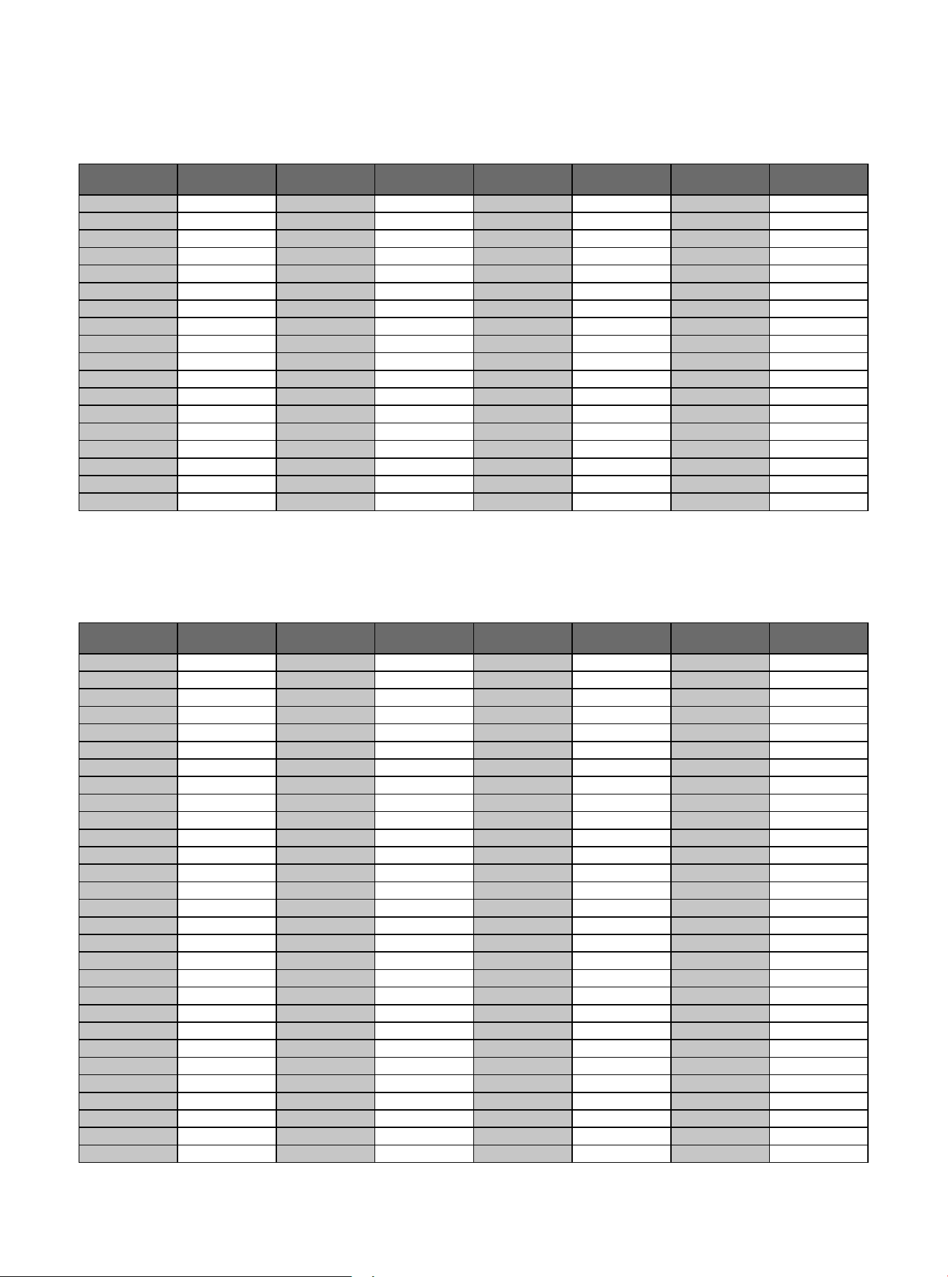
15.9 Temperature-Resistance Relationship Table (For T3 and T4 Sensors)
Temperature F Temperature C
Electric
Resistance kΩ
Volt DC
Electric
Resistance kΩ
Volt DCTemperature F Temperature C
Temperature F Temperature C
Electric
Resistance kΩ
Volt DC
Electric
Resistance kΩ
Volt DCTemperature F Temperature C
-5 -20.6
33.367 0.57
0 -17.8 29.227 0.64
5 -15.0 25.657 0.72
10 -12.2 22.595 0.80
15 -9.4 19.942 0.89
20 -6.7 17.697 0.98
25 -3.9 15.673 1.08
30 -1.1 13.917 1.18
40 4.4 11.060 1.40
45 7.2 9.867 1.52
50 10.0 8.823 1.64
55 12.8 7.884 1.76
60 15.6 7.101 1.89
65 18.3 6.409 2.01
70 21.1 5.767 2.14
75 23.9 5.150 2.28
80
-5 -20.6
-17.8
-15.0
-12.2
-9.4
-6.7
-3.9
-1.1
4.4
7.2
10.0
12.8
15.6
0
5
10
15
20
25
30
1.735
40
45
50
55
60
496.38 0.08
0.09
0.11
0.13
0.15
0.17
0.19
0.22
0.29
0.33
0.37
0.42
0.48
422.97
361.35
309.74
266.152
230.462
198.968
172.231
0.26149.467
130.642
113.87
99.456
87.095
76.425
60.0140 1.9712.348
62.8145 2.1011.164
65.6150 2.2210.106
68.3155 2.349.193
71.1160 2.468.344
73.9165 2.587.585
76.7
170
2.69
6.904
79.4175 2.806.313
82.2180 2.925.761
85.0185 3.025.263
87.8190 3.134.815
90.6195 3.234.410
93.3200 3.334.057
96.1205 3.423.724
65 18.3
21.1
23.9
26.7
29.4
32.2
35.0
37.8
43.3
46.1
48.9
51.7
54.4
70
75
80
85
90
95
100
40.6105
110
115
120
125
130
67.501 0.53
0.60
0.67
0.74
0.82
0.90
0.99
1.09
1.29
1.39
1.51
1.62
1.73
59.457
52.489
46.429
41.322
36.682
32.619
29.068
1.1925.948
23.291
20.855
18.708
16.809
15.184
57.2135 1.8513.682
98.9210 3.513.423
101.7215 3.603.149
104.4220 3.672.910
107.2225 3.752.689
110230 3.822.476
112.8235 3.892.288
115.6240 3.962.117
118.3245 4.021.965
121.1250 4.081.821
123.9
255
4.13
1.690
126.7260 4.191.569
129.4265 4.231.462
132.2270 4.281.360
135.0275 4.321.266
137.8280 4.361.180
26.7
4.700 2.39
85 29.4 4.266 2.51
90 32.2 3.865 2.63
95 35.0 3.508 2.75
100 37.8 3.187 2.87
105 40.6 2.900 2.99
110 43.3 2.652 3.09
115 46.1 2.421 3.20
120 48.9 2.214 3.30
125 51.7 2.025 3.40
130 54.4 1.861 3.49
135 57.2 1.706 3.58
140 60.0 1.567 3.66
145 62.8 1.442 3.74
150 65.6 1.327 3.82
155 68.3 1.226 3.89
160 71.1 1.132 3.96
165 73.9 1.046 4.02
170 76.7 0.967 4.08
Table 15.3 for T3, T4
15.10 Temperature-resistance relationship table (for T5 sensor)
Table 15.4 for T5
01 02 03 04 05 06 07 08 09 10 11 12 13 14 15 16 17 18 19
20 21 22 23 24 25 26 27 28 29 30 31 32
34
34 35 36
01 03 04 05 06 07 08
09 10 11 12 13 14 15 16 17 18
19 20 21 22 23 24 25 26 27 28
29 30 31 32 33 34
35 36 37
02
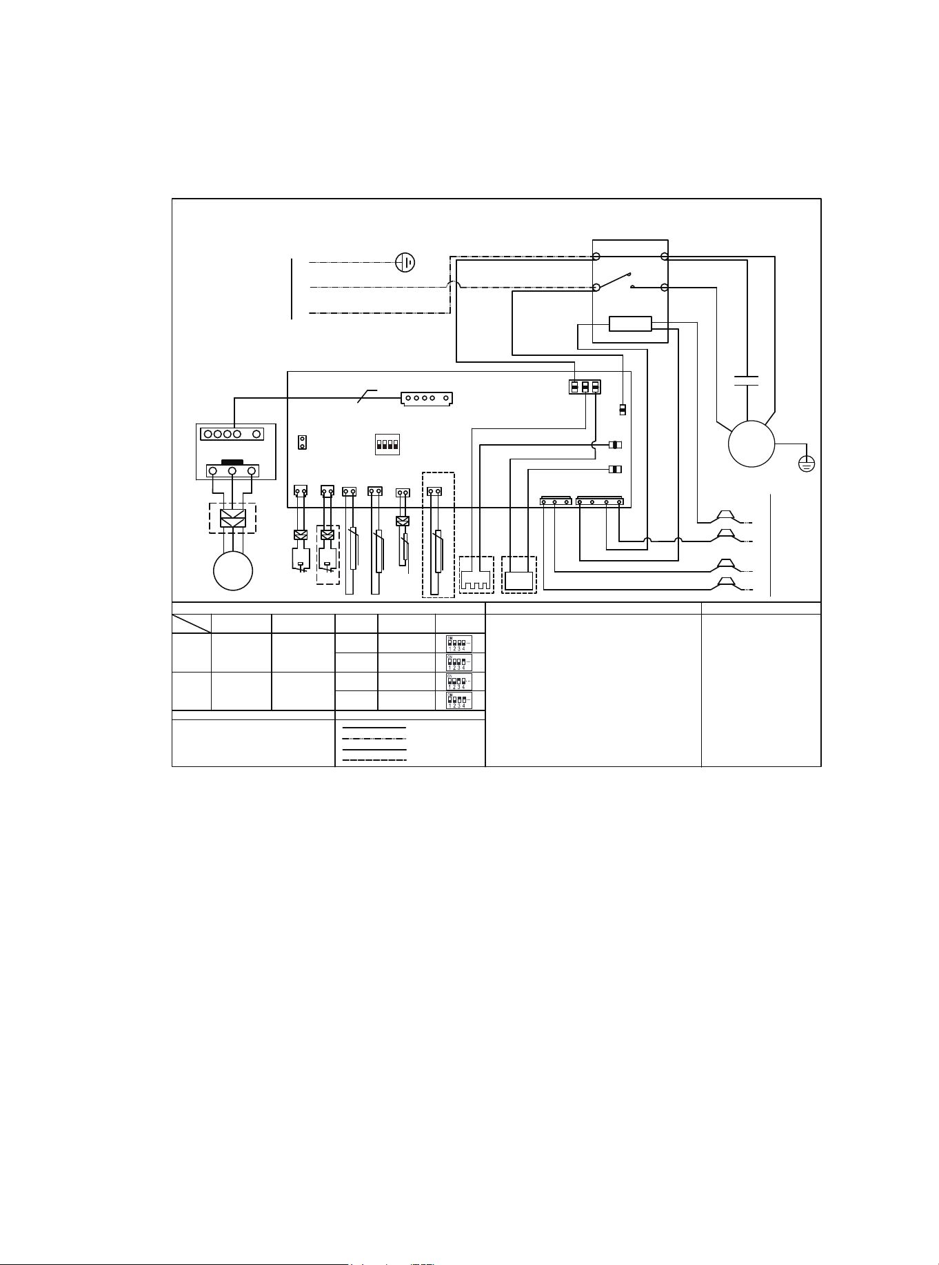
16 Wiring Diagram
WIRE COLOR CODE
NOTES
COMPONENT CODE
FACTORY CONNECTION
PROJECT CONNECTION
PRACTICALITY EXTERIOR
DASHED CIRCLE
L
DIP Switch Description
1#
T3
COMPRESSOR
TERMINAL BLOCK
CAPACITOR
CONTACTOR
WIRE INFORMATION
HP
LP
T5
DC FAN
5
N
2#
TEST
HP
HP
LP
DC DRIVER BOARD
P1
P4
LP
HEATER
T4
MEDIUM HIGH
MEDIUM
HIGH
LOW18K 24K
30K 36K 42K
48K 60K
Y
B
W1
C
R
COMP
W
L1
L2
T1
T2
A2
A1
KM
M
TB
C1
KM
YE YELLOW
BR BROWN
OR ORANGE
GN GREEN
BK BLACK
GY GREY
PR PURPLE
WH WHITE
HE HENNA
ON DP
1 2 3 4
SW1
HIGH PRESSURE SWITCH
LOW PRESSURE SWITCH
or brass wires.
3. The units should install the stated-cross-section earth wire and keep it
grounding unfailingly.
4.For indoor transformer, the current of 24V load voltage is not less than 1.5A.
Outdoor temp. sensor
Exhaust pipe temp. sensor
Ourdoor pipe temp. sensor
4-WAY 4-WAY VALVE COIL
HEATER CRANKSHAFT HEATING BAND
1. The units should use the unattached power switch, stated-cross-section
wires and matching-spec. breaker.
2. Use the fuse within the specified scope, it can not replaced by iron wires
Timed defrost(40min)
High vertical mode
NUMBER
Automatic Defrost Gerenal mode
BK
RD
BL
BL
BK
YE
BR
OR
OR
FAN B
TO POWER
BK
BL
YE/GN
BK
BL
C1
C
S
R
YE/GN
HEATER
Wiring Diagram
M
~
Model
FAN SPEED TAPS
C
Y
TO THERMOSTAT
/
SW1
BL BLUE
RD RED
DIAL STATE
ON
OFF
W
PR
B
BL
4-WAY
4-WAY
BL
BL
TH
Suction pipe temp. sensor
NOTE: For reference only, the actual wiring diagram shall prevail
Figure 16.1 Wiring Diagram for HP Systems
01 03 04 05 06 07 08
09 10 11 12 13 14 15 16 17 18
19 20 21 22 23 24 25 26 27 28
29 30 31 32 33 34 35
36 37
02
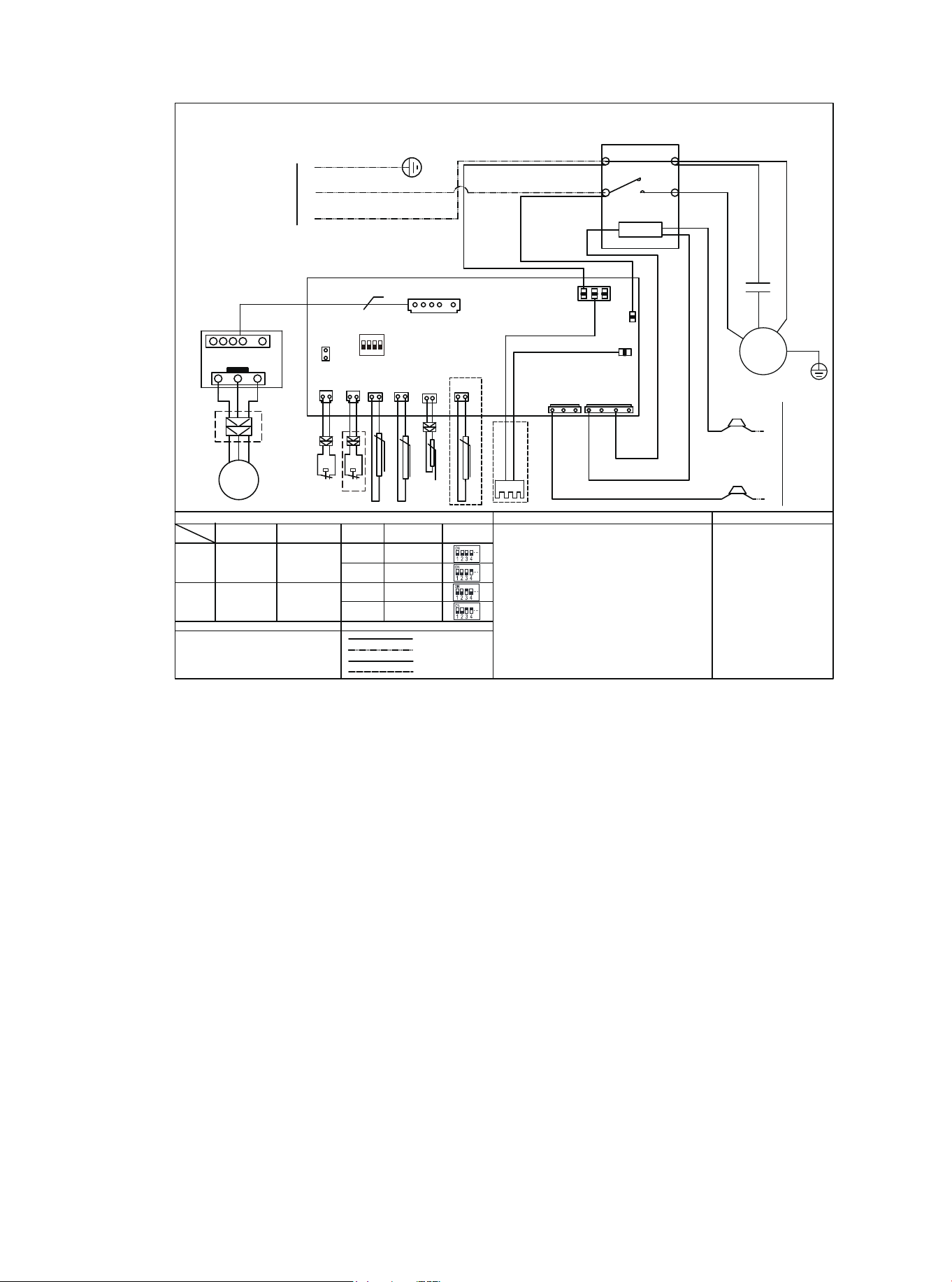
WIRE COLOR CODE
NOTES
COMPONENT CODE
FACTORY CONNECTION
PROJECT CONNECTION
PRACTICALITY EXTERIOR
DASHED CIRCLE
L
DIP Switch Description
1#
COMPRESSOR
TERMINAL BLOCK
CAPACITOR
CONTACTOR
WIRE INFORMATION
DC FAN
5
N
2#
TEST
HP
LP
DC DRIVER BOARD
P1
P4
HEATER
MEDIUM HIGH
MEDIUM
HIGH
LOW18K
24K 30K 36K
42K 48K
Y
B
W1
C
R
COMP
W
L1
L2
T1
T2
A2
A1
KM
M
TB
C1
KM
YE YELLOW
BR BROWN
OR ORANGE
GN GREEN
BL BLUE
BK BLACK
RD RED
GY GREY
PR PURPLE
WH WHITE
HE HENNA
ON DP
1 2 3 4
SW1
HIGH PRESSURE SWITCH
LOW PRESSURE SWITCH
or brass wires.
3. The units should install the stated-cross-section earth wire and keep it
grounding unfailingly.
4.For indoor transformer, the current of 24V load voltage is not less than 1.5A.
4-WAY 4-WAY VALVE COIL
HEATER CRANKSHAFT HEATING BAND
1. The units should use the unattached power switch, stated-cross-section
wires and matching-spec. breaker.
2. Use the fuse within the specified scope, it can not replaced by iron wires
Timed defrost(40min)
High vertical mode
DIAL STATE
ON
OFF
NUMBER
Automatic defrost General mode
BK
RD
BL
BL
BK
YE
BR
OR
OR
FAN B
TO POWER
BK
BL
YE/GN
BK
BL
C1
C
S
R
YE/GN
HEATER
Wiring Diagram
M
~
Model
FAN SPEED TAPS
C
Y
TO THERMOSTAT
60K
SW1
T3
HP
LP
T5
HP
LP
T4
Outdoor temp. sensor
Exhaust pipe temp. sensor
Ourdoor pipe temp. sensor
TH
Suction pipe temp. sensor
NOTE: For reference only, the actual wiring diagram shall prevail
Figure 16.2 Wiring Diagram for AC Systems
Warning:
● Any cleaning of outdoor units can only be carried out by qualified maintenance
personnel.
● Any unit maintenance can only be carried out by qualified maintenance personnel.
Caution: Electric Shock
● Be sure to turn off the unit and disconnect the power supply before cleaning or
maintenance.
Note:
● Do not use chemicals or chemically treated cloth to clean the unit.
● Do not use benzene, paint thinner, polishing powder or other solvents to clean this unit.
Caution:
● When removing the filter, avoid touching the metal parts inside the unit. Sharp metal
edges can cause bodily harm.
17.1 Cleaning Precautions
17 Cleaning and Maintenance
Table 17.1
17.2 Pre-Season Inspection and Maintenance
At the start of each heating or cooling season, do the following:
Turn off the unit and disconnect the power supply.
Check for damaged wires & leaks.
Make sure that all air inlets and outlets are not blocked.
01 02 03 04 05 06 07 08 09 10 11 12 13 14 15 16 17 18 19
20 21 22 23 24 25 26 27 28 29 30 31 32 33 34 35
37
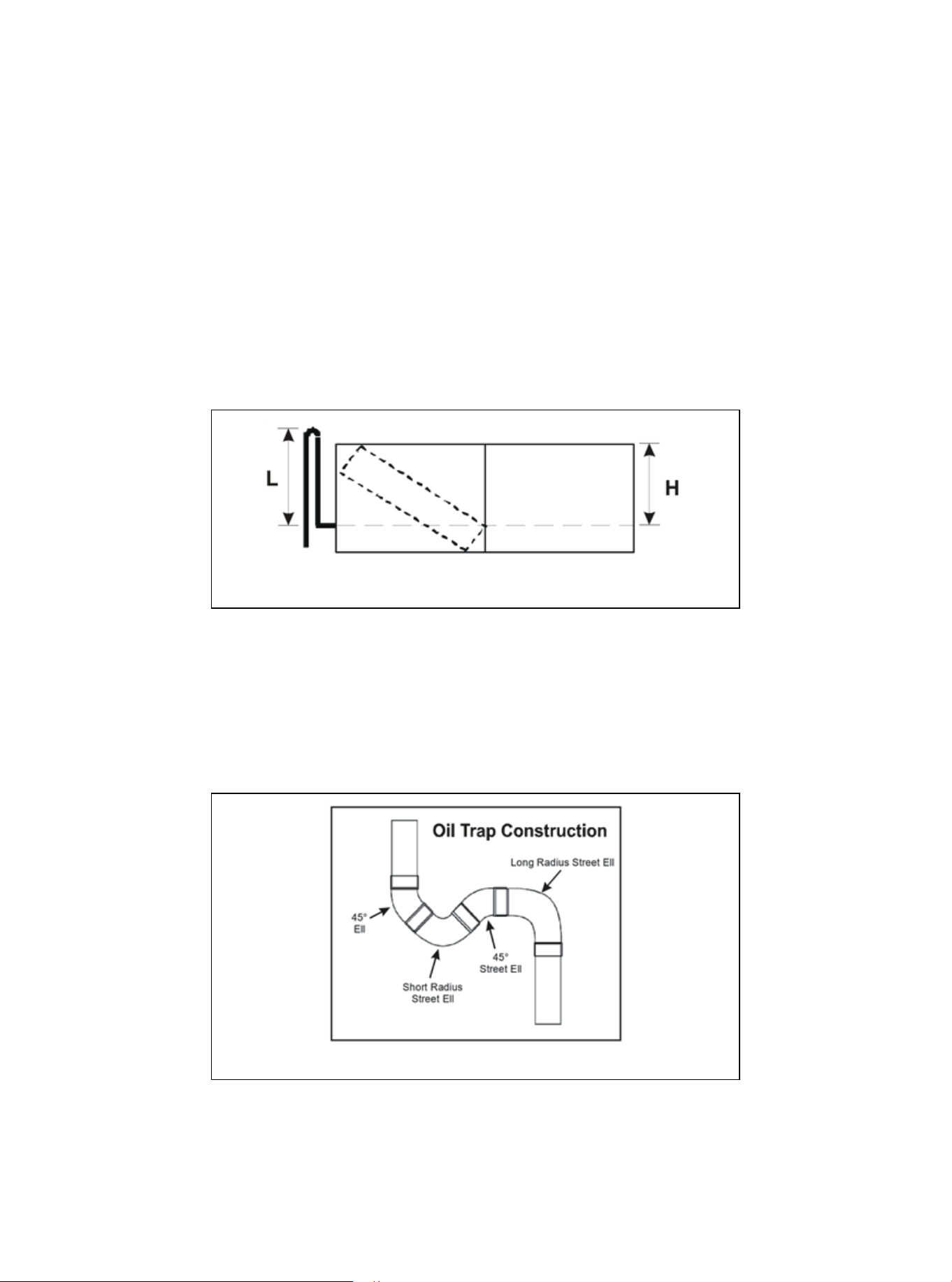
Figure 1
Figure 2
Appendix 1
High Vertical Lift Installation Requirements
1. In a completely horizontal long piping installation, if the evaporator and the condenser are at the same
height (or slightly lower than the condenser), the pipeline set should be inclined towards the evaporator.
This helps to reduce the refrigerant return to the condenser during the closed cycle of the air conditioning
system.
2. For the installation of the system where the evaporator is located above the condenser, a reversed
vapor line trap should be installed on the suction pipe before the evaporator inlet (see Figure 1). The top
of the reverse loop must be slightly higher than the top of the evaporator. If the bending tool cannot be
used, it can be created by brazing two 90 ° long radius elbows together. Correctly support the reverse
loop and fix it at the nearest point on the indoor unit or adjacent structure.
3. When the condenser is located above the evaporator and the height difference is greater than 15 ft, it
is necessary to set the oil trap at the evaporator. Most HVAC supply houses have preformed oil trap, or
pipe elbows can be brazed together to form oil trap(see the figure below).
Remember to add the equivalent length of the oil traps in the calculation of the equivalent length of the
suction pipe. For example, if two 45 ° elbows, a short elbow and a 90 ° long elbow are used in the
suction pipe with a diameter of ¾″ to construct the oil trap, the additional equivalent length is
0.7+0.7+1.7+1.5, which is equal to 4.6 feet.
01 03 04 05 06
07 08 09 10 11 12 13 14
15 16 17 18 19 20 21 22
23 24 25 26 27 28 29 30
31 32 33 34 35 36 37
02
38
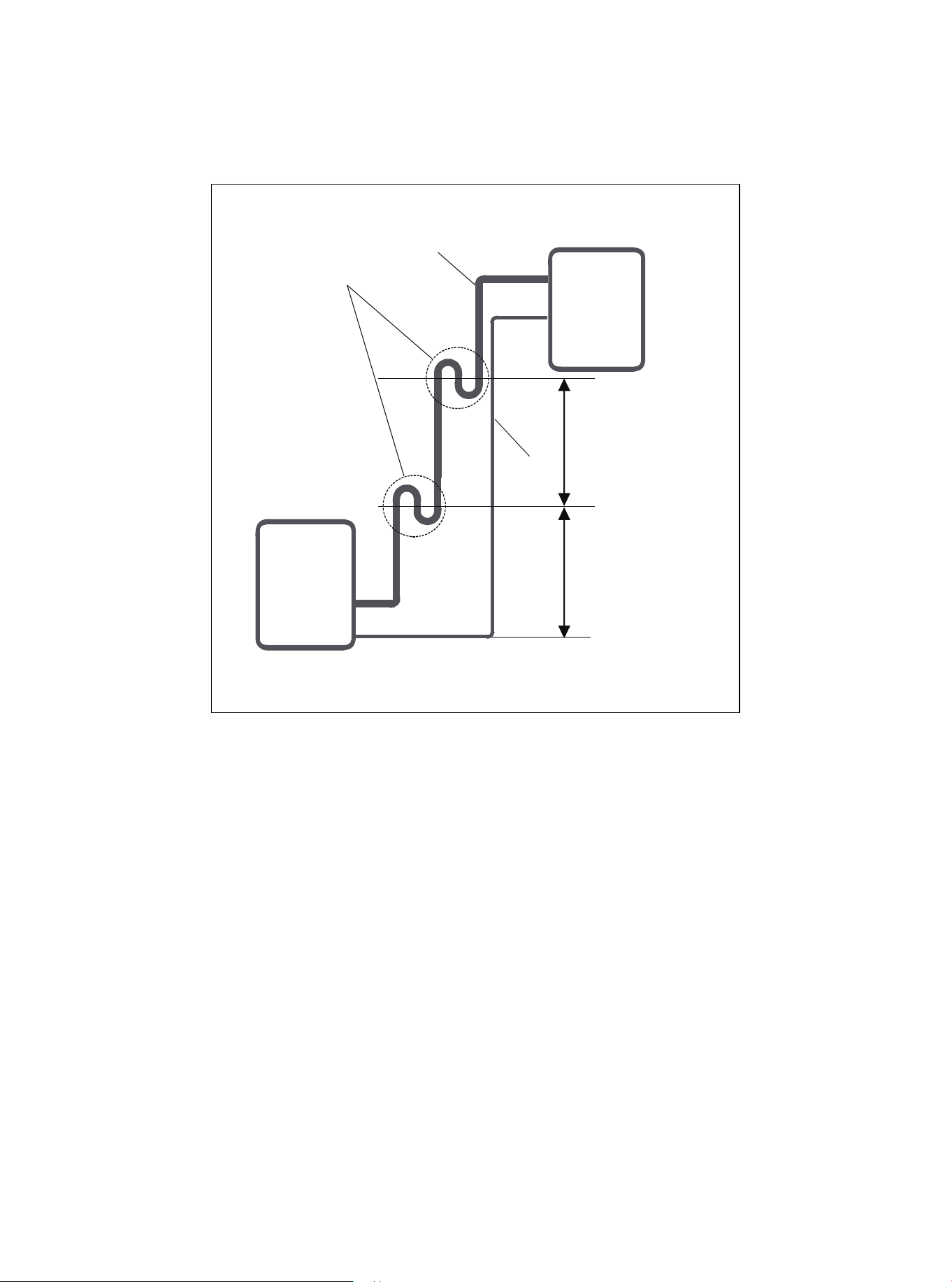
Figure 3
4.If oil flows back into the outdoor unit’s compressor, this might cause liquid compression or deteriora-
tion of oil return. Oil traps in the rising gas piping can prevent this.
An oil trap should be installed every 6 m (20ft) of vertical suction line riser.
6m/20ft
Liquid
piping
Gas piping
Oil trap
6m/20ft
Indoor unit/Outdoor unit
Indoor unit/
Outdoor unit
39

PRODIRECT™ Series
Split System Heat Pump & Air Conditioner
15SEER/ 14.3SEER2 1.5-5 Tons Model
HHP150* & HAC150*
The design and specifications of this product and/or manual are subject to change without prior notice.
Consult with the sales agency or manufacturer for details.