VersaPro™
Gas Package Unit
Installation Manual
MODELS:
Read this manual carefully before installation and keep it where
the operator can easily nd it for future reference.
Due to updates and constantly improving performance, the
information and instructions within this manual are subject to
change without notice.
Version Date: 07/16/24
Please visit www.mrcool.com/documentation
to ensure you have the latest version of this manual.
• MPG24S060M413B
• MPG30S060M413B
• MPG36S090M413B
• MPG42S090M413B
• MPG48S090M413B
• MPG60S110M413B

mrcool.com1
CONTENTS
SAFETY ............................................................................................................................... 2
UNIT OVERVIEW ................................................................................................................ 7
2.1 Inspection ............................................................................................................. 7
2.2 Limitations .......................................................................................................... 7
2.3 Unit Description ................................................................................................... 7
2.4 Dimensions ........................................................................................................... 8
INSTALLATION ................................................................................................................ 14
3.1 Pre-Installation Checkpoints ............................................................................ 14
3.2 Location Considerations ................................................................................... 14
3.3 Outside Installation ........................................................................................... 14
3.4 Attaching Exhaust & Combustion Air Inlet Hoods ......................................... 15
3.5 Cover Panel Installation / Conversion Procedure ......................................... 15
3.6 Clearance ............................................................................................................ 16
3.7 Rigging & Handling ............................................................................................ 17
3.8 Roof Curb ............................................................................................................ 19
3.9 Ductwork ............................................................................................................ 20
3.10 Return Air .......................................................................................................... 20
3.11 Filters ................................................................................................................. 20
GAS SUPPLY, CONDENSATE DRAIN, & PIPING ............................................................ 20
4.1 Gas Connection .................................................................................................. 20
4.2 Conversion ......................................................................................................... 22
4.3 Adjusting or Checking Furnace Input .............................................................. 23
4.4 Condensate Drain .............................................................................................. 24
WIRING ............................................................................................................................ 24
5.1 Power Supply ..................................................................................................... 24
5.2 Hook-Up .............................................................................................................. 25
5.3 Internal Wiring ................................................................................................... 26
5.4 Thermostat ......................................................................................................... 26
FURNACE SECTION CONTROLS & IGNITION SYSTEM ................................................. 27
6.1 Normal Furnace Operating System ................................................................. 27
6.2 Operating Instructions ...................................................................................... 27
6.3 Starting the Furnace ......................................................................................... 28
6.4 Shutting Down the Furnace ............................................................................. 28
6.5 Burners ............................................................................................................... 29
6.6 Manual Reset Over Temperature Control ...................................................... 29
6.7 Pressure Switch ................................................................................................. 29
6.8 Limit Control ...................................................................................................... 29
SYSTEM OPERATING INFORMATION ............................................................................ 29
7.1 User Reminders ................................................................................................. 29
7.2 Furnace Section Maintenance ......................................................................... 29
7.3 Lubrication ......................................................................................................... 31
7.4 Cooling Section Maintenance .......................................................................... 31
7.5 Replacement Parts ............................................................................................ 32
7.6 Wiring Diagram .................................................................................................. 32
7.7 Charging .............................................................................................................. 32
7.8 Blower Motor Speed Taps ................................................................................ 32
1
Contents
2
3
4
5
6
7
mrcool.com 2 2
Contents
OPERATION ..................................................................................................................... 33
8.1 Control System Operation ................................................................................ 33
8.2 Fan Delay Adjustment ....................................................................................... 33
SEER2 PHYSICAL DATA ................................................................................................... 35
AIRFLOW PERFORMANCE .............................................................................................. 37
10.1 Indoor Airow Performance-230 Volts .......................................................... 37
10.2 Motor Speed from Factory .............................................................................. 39
TROUBLESHOOTING & WIRING DIAGRAMS ................................................................ 40
11.1 Troubleshooting Chart .................................................................................... 40
11.2 High Altitude .................................................................................................... 42
11.3 Fuse Parameters .............................................................................................. 42
11.4 Wiring Diagrams .............................................................................................. 43
Safety Precautions
Read Before Using
Incorrect usage may cause serious damage or injury.
Keep this manual for future reference.
These instructions do not cover all of the dierent variations of systems nor does it provide for every possible
contingency to be met in connection with installation.
WARNING: FIRE & EXPLOSION
FAILURE TO FOLLOW SAFETY WARNINGS COULD RESULT IN SERIOUS INJURY, DEATH, OR PROPERTY
DAMAGE.
INSTALLATION & SERVICE MUST BE PERFORMED BY A LICENSED PLUMBER OR GAS FITTER FOR
APPROPRIATE FUEL.
DO NOT store gasoline or other ammable vapors and liquids in the vicinity of the unit or any
other appliance.
What to do if you smell gas:
• Do not attempt to light any appliance, touch any electrical switches, or use any phone in
the building.
• Immediately call your gas supplier from a phone outside of the building and follow the gas
supplier's instructions.
• If you cannot reach your gas supplier, call the re department.
• Do not return to your home until authorized by the gas supplier or re department.
CAUTION
Indicates the most serious hazards which will result in severe
personal injury, property and/or product damage, or death.
Indicates hazards which could result in moderate personal
injury and/or property and product damage.
Indicates suggestions which will result in enhanced
installation, reliability, or operation.
WARNING
NOTE
CONTENTS, CONTD.
10
11
8
9
mrcool.com3
SAFETY
1
CAUTION: LOCATION SELECTION
2. The unit is design-certied for use with natural and propane gases (see furnace rating plate) and
for installation outside only. The furnace is factory-shipped for use with natural gas only. A listed
accessory gas conversion kit is required to convert furnace for use with propane gas. The LP
conversion kit is included with the unit.
3. The furnaces must be kept free and clear of insulating materials. Inspect the surrounding area
to ensure insulation material is in safe distance when installing furnace or adding insulation
materials. Insulation materials may be combustible.
4. Furnace operation needs air for combustion and ventilation. Do not block or obstruct air openings
on furnace or spacing around furnace required for supplying sucient combustion air and
ventilation.
NOTE FOR OPTIMAL OPERATION
Before heating season begins, examine the furnace to determine that:
• All ue gas carrying areas external to the furnace (i.e. chimney, vent connector) are clear and free
of obstructions.
• The vent connector is in place, slopes upward, and is physically sound without holes or excessive
corrosion.
• The return-air duct connection(s) is physically sound, is sealed to the unit casing, and terminates
outside the space containing the unit.
• The physical support of the furnace is sound without sagging, cracks, gaps, etc. around the base so
as to provide a seal between the support and the base.
• There are no obvious signs of deterioration of the unit.
• The burner ames are adjusted appropriately.
WARNING: FIRE & EXPLOSION (CONTD.)
• The furnace is designed and approved for use with Natural Gas ONLY. DO NOT BURN ANY LIQUID
FUEL OR SOLID FUEL IN THIS UNIT.
• Burning any unapproved fuel will result in damage to the unit heat exchanger, which could result in
re, Carbon Monoxide poisoning, explosion, personal injury, property damage and/or death.
• Do not use this furnace if any part has been under water. A ood-damaged furnace is extremely
dangerous. Attempts to use the furnace can result in re or explosion. A qualied service agency
should be contacted to inspect the furnace and to replace all gas controls, control system parts, and
electrical parts that have been wet. Replacement of the furnace may be deemed necessary.
WARNING: PROPOSITION 65
• This appliance contains berglass insulation. Respirable particles of berglass are known to the
state of California to cause cancer. Exhaust gas from this appliance contains chemicals, including
carbon monoxide, known to the state of California to cause birth defects of other reproductive
harm.

mrcool.com 4
4
SAFETY
1
GENERAL WARNINGS FOR SAFETY
• Improper adjustment, alteration, service, maintenance or installation can cause serious injury or
death. Read and follow instructions and precaution in User’s Information Manual provided with
this furnace. Installation and service must be performed by a qualied service agency or the gas
supplier.
• Should the gas supply fail to shut o or if overheating occurs, shut o the manual gas valve to the
furnace before shutting o the electrical supply.
• Never test for gas leaks with an open ame. Use a commercially available soap solution made
specically for the detection of leaks to check all connections, as specied in this manual.
• This appliance is not intended for use by persons (including children) with reduced physical,
sensory, or mental capabilities, or lack of experience and knowledge, unless they have been given
supervision or instruction concerning use of the appliance by a person responsible for their safety.
• Children should be supervised to ensure they do not play with the unit.
• These instructions are intended as an aid to qualied, licensed service personnel for proper
installation, adjustment and operation of this unit. Read these instructions thoroughly before
attempting installation or operation. Failure to follow these instructions may result in improper
installation, adjustment, service or maintenance possibly resulting in re, electrical shock, property
damage, personal injury or death.
• The manufacturer’s warranty does not cover any damage or defect to the gas/electric unit caused
by the attachment or use of any components, accessories or devices (other than those authorized
by the manufacturer) into, onto or in conjunction with the gas/electric unit. You should be
aware that the use of unauthorized components, accessories or devices may adversely aect the
operation of the gas/electric unit and may also endanger life and property. The manufacturer
disclaims any responsibility for such loss or injury resulting from the use of such unauthorized
components, accessories or devices.
• Do not, under any circumstances, connect return ductwork to an other heat producing device
such as a replace insert, stove, etc. Unauthorized use of such devices may result in re, Carbon
Monoxide poisoning, explosion, property damage, severe personal injury or death.
• This unit is designed certied for outdoor installation only. Installation inside any part of a
structure can result in inadequate unit performance as well as property damage. Installation inside
can also cause recirculation of ue products into the conditioned space resulting in personal injury
or death.
• The spark igniter and ignition lead from the ignition control are high voltage. Keep hands or tools
away to prevent electrical shock. Shut o electrical power before servicing any of the controls.
Failure to adhere to this warning can result in personal injury or death.
• Never allow products of combustion or the ue products to enter the return air ductwork, or the
circulating air supply. All return ductwork must be adequately sealed and secured to the furnace
with sheet metal screws, and joints taped. All other duct joints must be secured with approved
connections and sealed airtight. Failure to prevent products of combustion from being circulated
into the living space can create potentially hazardous conditions, including Carbon Monoxide
poisoning that could result in personal injury or death.
• Holes in the exhaust transition or heat exchanger can cause toxic fumes to enter the home. The
exhaust transition or heat exchanger must be replaced if they have holes or cracks in them. Failure
to do so can cause Carbon Monoxide poisoning resulting in personal injury or death.
• All phases of this installation must comply with national, state, and local codes. If additional
information is required, contact your local distributor.
• Wear safety glasses, protective clothing, and work gloves.
• Have a re extinguisher available.
• Read these instructions thoroughly as well as those attached to the unit.
• Improper installation or misapplication of furnace may require excessive servicing or cause
premature component failure. Application of this furnace should be indoors with special attention
given to vent sizing and material, gas input rate, air temperature rise, unit leveling, and unit sizing.

mrcool.com5
SAFETY
1
GENERAL WARNINGS FOR SAFETY
• Always install furnace to operate within the furnace's intended temperature-rise range with a
duct system which has an external static pressure within the allowable range. Also see the furnace
rating plate.
• When the unit is installed so that supply ducts carry air circulated by the furnace to areas outside
the space containing the furnace, the return air shall also be handled by duct(s) sealed to the
furnace casing and terminating outside the space containing the unit.
• The furnace may be used for construction heat provided that the furnace installation and operation
complies with the requirements safety warnings within this manual.
• Do not attempt to manually light this furnace with a match or any open ame. Attempting to do so
can cause re or explosion resulting in property damage, personal injury or death.
• Disconnect all power to the unit before starting maintenance. Failure to do so can result in severe
electrical shock or death. Regular maintenance will reduce the buildup of contaminants and help to
protect the unit’s nish.
• Turn o the main electrical power at the branch circuit disconnect closest to the unit before attempting
any wiring. Failure to do so can cause electrical shock resulting in personal injury or death.
• DO NOT JUMPER THIS DEVICE! Do not reset the over temperature control without taking corrective
action to assure that an adequate supply of combustion air is maintained under all conditions of
operation. Failure to do so can result in Carbon Monoxide poisoning or death. Replace this control only
with the identical replacement part.
• Install this unit only in a location and position as specied in the location requirements and
considerations section of these instructions. Provide adequate combustion and ventilation air to the
unit space as specied in the venting section of these instructions.
• Do not use this unit during construction if air laden corrosive compounds are present such as chlorine
and uorine. Otherwise, provisions must be taken to provide clean, uncontaminated combustion and
ventilation air to the unit, combustion and ventilation air contaminated with these compounds forms
acids during combustion which corrodes the heat exchanger and component parts, some of these
contaminates are found in, but not limited to, paneling, dry wall, adhesives, paints, stains, varnishes,
sealers, and masonry cleaning materials.
• Improper installation, adjustment, alteration, service, maintenance or use could cause carbon
monoxide poisoning, explosion, re, electrical shock or other conditions which may cause personal
injury or property damage. Consult a qualied service agency,local gas supplier or your distributor or
branch for information or assistance. The qualied service agency must use only factory-authorized
and listed kits or accessories when modifying this product.
• R410A systems operate at higher pressures than R22 systems. Do not use R22 service equipment or
components on R410A equipment.
• Improper installation, adjustment, alteration, service, maintenance, or use can cause explosion, re,
electrical shock, or other conditions which may cause death, personal injury, or property damage.
Consult a qualied installer, service agency, or your distributor or branch for information or assistance.
The qualied installer or agency must use factory-authorized kits or accessories when modifying this
product.
• Refer to the individual instructions packaged with the kits or accessories when installing.
• Consult local building codes, the current editions of the National Fuel Gas Code (NFGC) NFPA 54/ANSI
Z223.1 and the National Electrical Code (NEC) NFPA 70.
• A manufactured (mobile) home installation must conform with the Manufactured Home Construction
and Safety Standard, Title 24 CFR, Part 3280, or when this Standard is not applicable, the Standard for
Manufactured Home Installations (Manufactured Home Sites, Communities and Set-Ups), ANSI/NCS
A225.1, and/or MH Series Mobile Homes, CAN/CSA Z240.
• In Canada, refer to the current editions of the National Standards of Canada CAN/CSA-BI49.1 and .2
Natural Gas and Propane Installation Codes, and Canadian Electrical Code CSA C22.1
• Use only with type of gas approved for this unit. Refer to the unit rating plate.
• Install this unit only in a location and position as specied in the "Installation" section of these
instructions.
• Provide adequate combustion and ventilation air to the unit space.
mrcool.com 6
6
SAFETY
1
FOR YOUR SAFETY, READ BEFORE OPERATING.
WARNING: If these instructions are not followed exactly, it may result in a re or explosion causing property
damage, personal injury, or loss of life.
A. This appliance does not have a pilot. It is equipped with an ignition device which automatically lights the
burner. DO NOT try to light the burner by hand.
B. Before operating, smell all around the appliance area for gas. Be sure to smell next to the oor as some gas
is heaver than air and will setting on the oor.
What to do if you smell gas:
• Do not try to light any appliance.
• Do not touch any electrical switch; do not use a phone inside the building.
• Immediately call your gas supplier from a phone outside of the building. Follow the gas supplier's
instructions.
• If you cannot reach your gas supplier, call the re department.
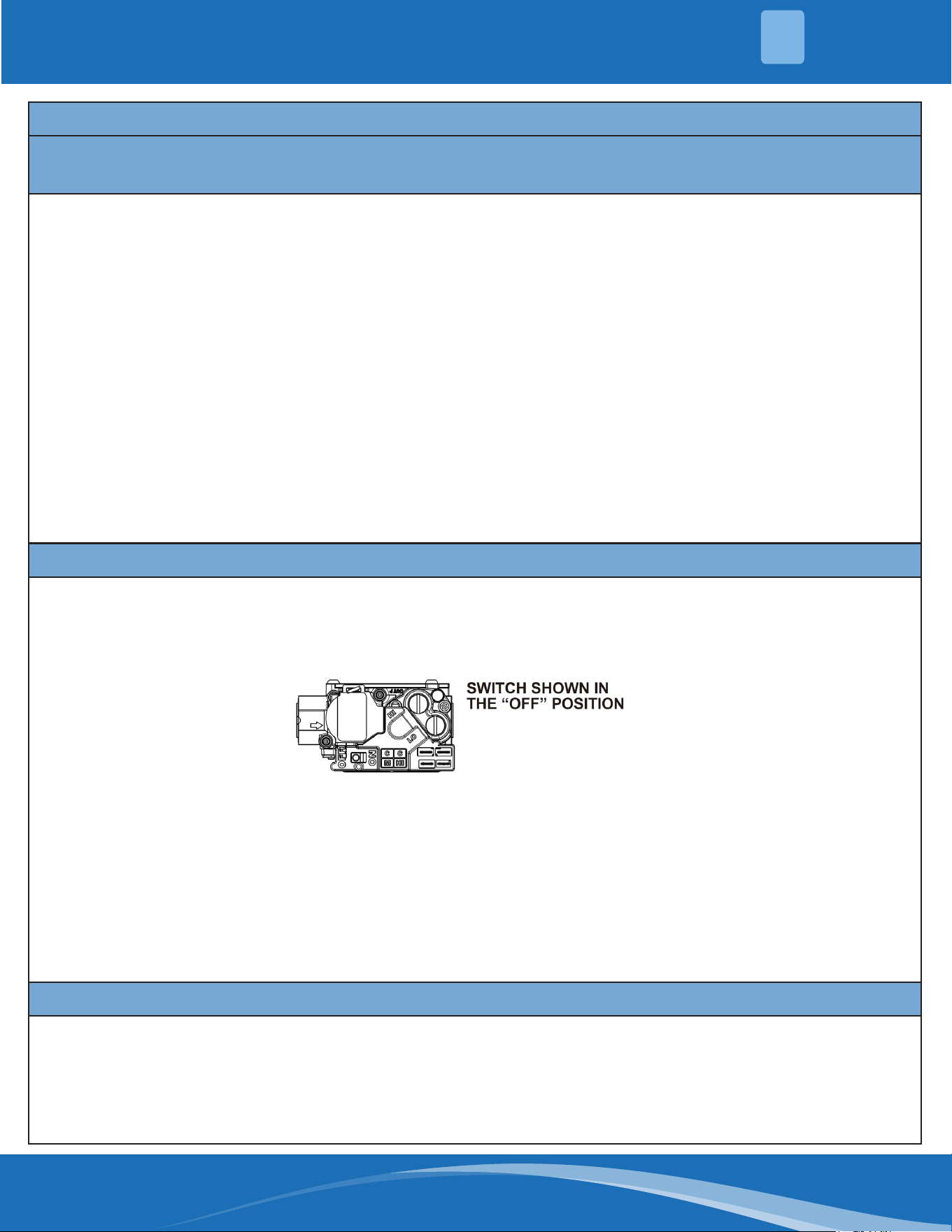
C. Use only your hand to turn the gas control switch. Never use tools. If the switch will not turn by hand, do not
try to repair it; call a qualied service technician. Force or attempted repair may result in a re or explosion.
D. Do not use this appliance if any part has been under water. Immediately call a qualied service technician
to inspect the appliance and to replace any part of the control system and any gas control which has been
under water.
OPERATING INSTRUCTIONS:
1. STOP! Read the safety information above on this label.
2. Set the thermostat to lowest setting.
3. Turn o all electric power to the appliance.
4. This appliance is equipped with an ignition device which automatically lights the burner. Do not try to light
the burner by hand.
5. Remove control access panel.
6. Wait ve (5) minutes to clear out any gas. If you smell gas, STOP. Follow "B" in the safety information above.
If you don't smell gas, go to the next step.
7. Push gas control switch to "ON". Do not force.
8. Replace control access panel.
9. Turn on all electric power to the appliance.
10. Set the thermostat to the desired setting.
11. If the appliance will not operate, follow the instructions below regarding turning o the gas to the
appliance and call your service technician or gas supplier.
TURNING OFF GAS TO APPLIANCE
1. Set the thermostat to its lowest setting.
2. Turn o all electric power to the appliance if service is to be performed.
3. Remove control access panel.
4. Push gas control to "OFF". Do not force.
5. Replace control access panel.

mrcool.com7
2.1 Inspection
As soon as unit is received, it should be inspected and noted for possible shipping damage during transportation.
It is shipper’s responsibility to cover the cost of shipping damage. Manufacturer or distributor will not accept the
claims from dealer for any transportation damage.
2.2 Limitations
If components are to be added to a unit they must meet local codes, they are to be installed at the dealer’s and /or
the customer’s expense. Size of unit for proposed installation should be based on heat loss / heat gain calculations
made in accordance with industry recognized procedures identied by the Air Conditioning Contractors of America.
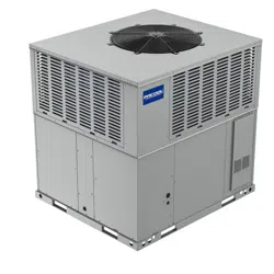
2.3 Unit Description
A Package Gas Electric Unit is a fully self-contained, combination gas heating/electric cooling unit designed
for outdoor installation. All unit sizes have return and discharge openings for both horizontal and downow
congurations, and are factory shipped with all downow duct openings covered. Units may be installed either on
a rooftop or on a cement slab.
In gas heating mode, this unit is designed for a minimum continuous return-air temperature and a maximum
continuous return-air temperature. Failure to follow these return-air temperature limits may aect reliability of
heat exchangers, motors, and other components.
This manual contains the installation and operating instructions for your Package Gas Electric Unit. There are
some precautions that should be taken to derive maximum satisfaction from it. Improper installation can result in
unsatisfactory operation or dangerous conditions. Read this manual and any instructions packaged with separate
equipment required to make up the system prior to installation. Give this manual to the owner and explain its
provisions.
The owner should retain this manual for future reference.
A Package Gas Electric Unit includes a hermetically-sealed refrigerating system consisting of a compressor,
condenser coil, evaporator coil with thermal expansion valve (TXV) or throttle valve, a circulation air blower, a
condenser fan, a heat exchanger assembly, gas burner and control assembly, combustion air motor and fan,
and all necessary internal electrical wiring. The cooling system of these units is factory-evacuated, charged and
performance tested. All units are factory charged with Refrigerant R410A.
The gures shown in this manual is for reference only and may be slightly dierent from the actual product.
UNIT OVERVIEW
2
mrcool.com 8
8
UNIT OVERVIEW
2
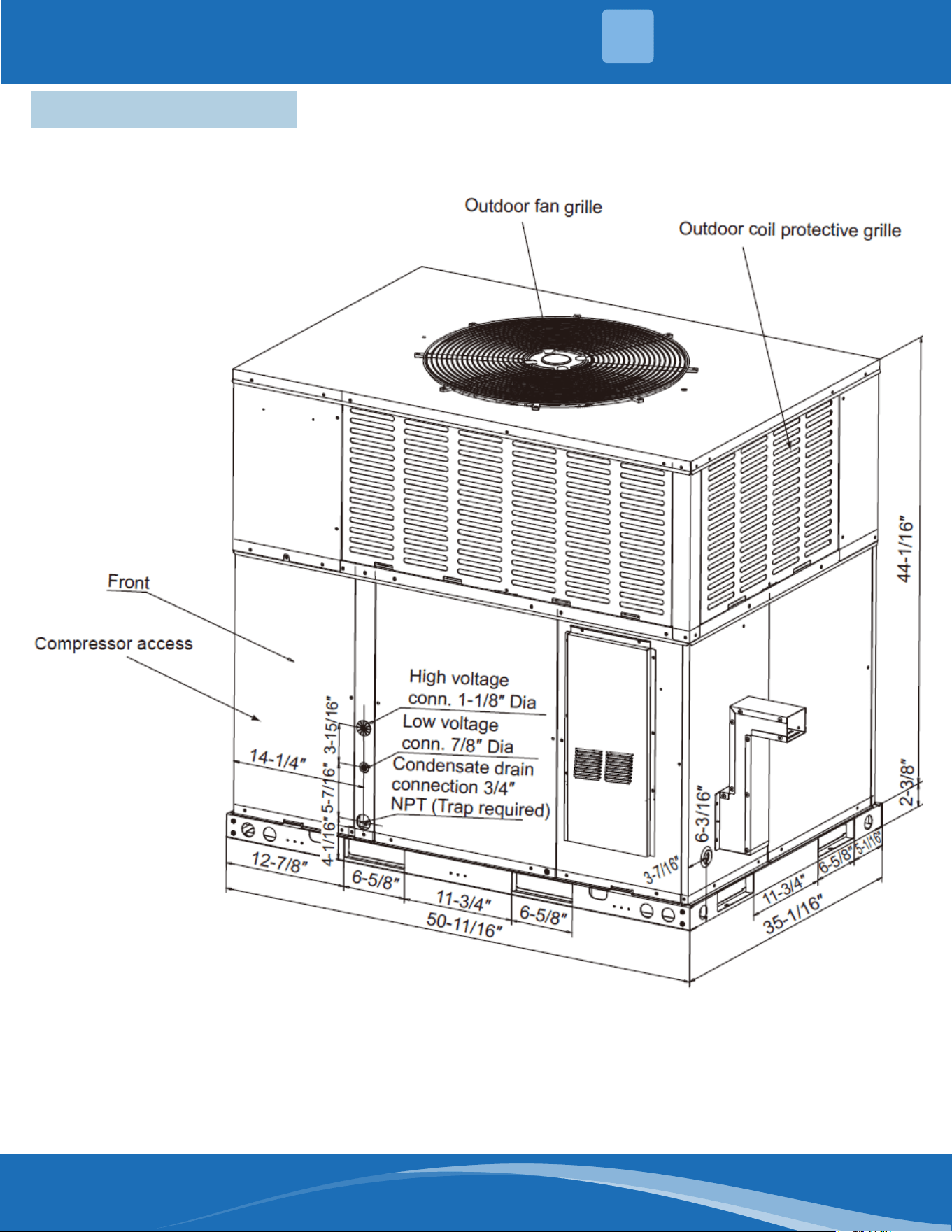
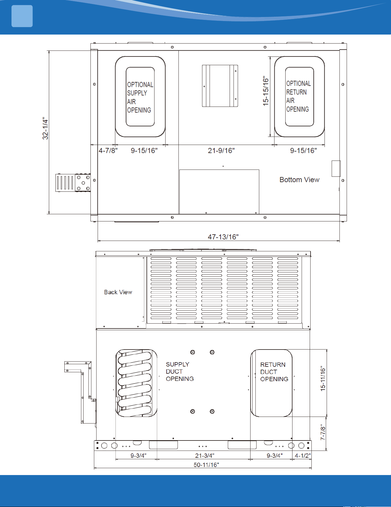
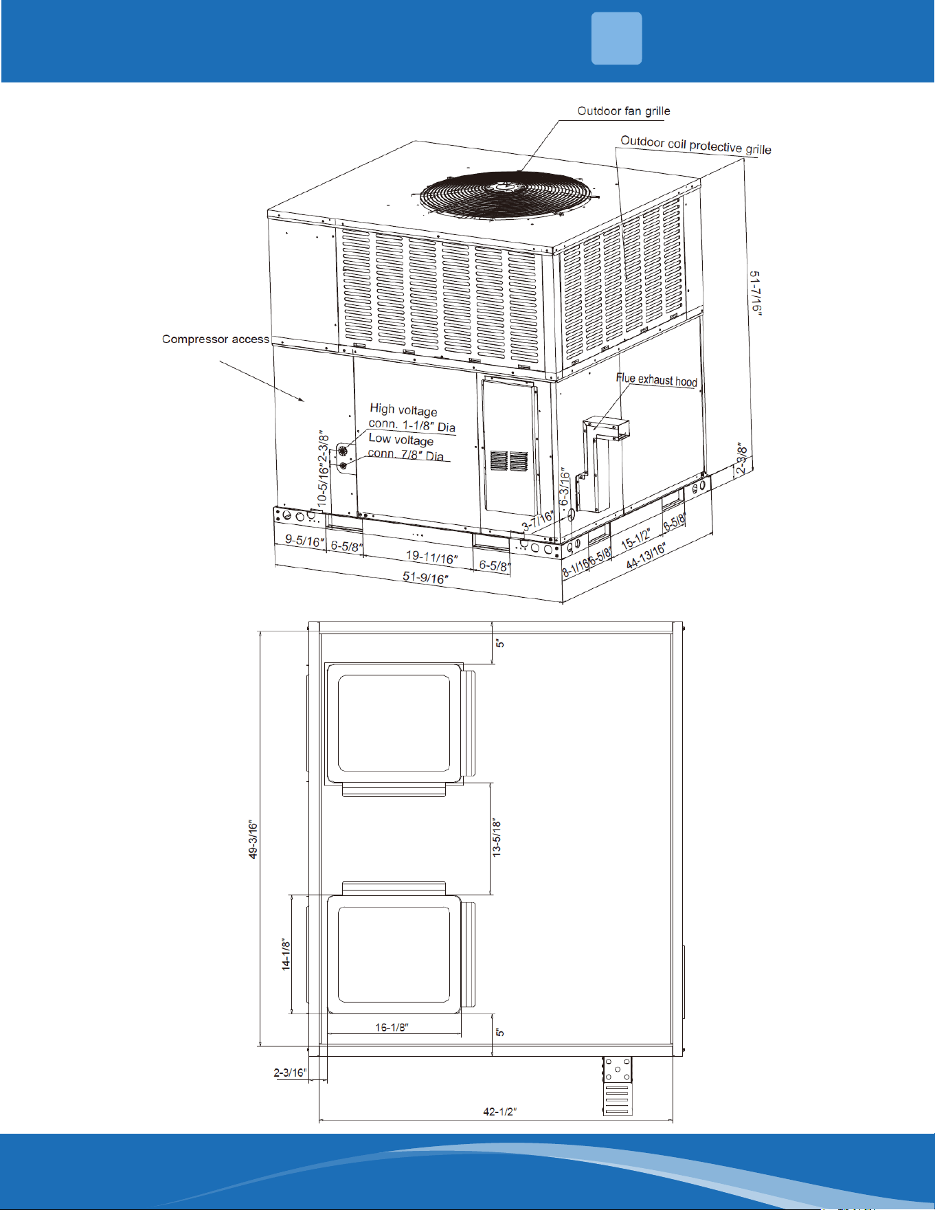
2.4 Dimensions
MPG24S060M413B, MPG30S060M413B, MPG36S090M413B, MPG42S090M413B
Figure 2.1a-
Unit Dimensions
*The above gure is for reference purposes only.
mrcool.com9
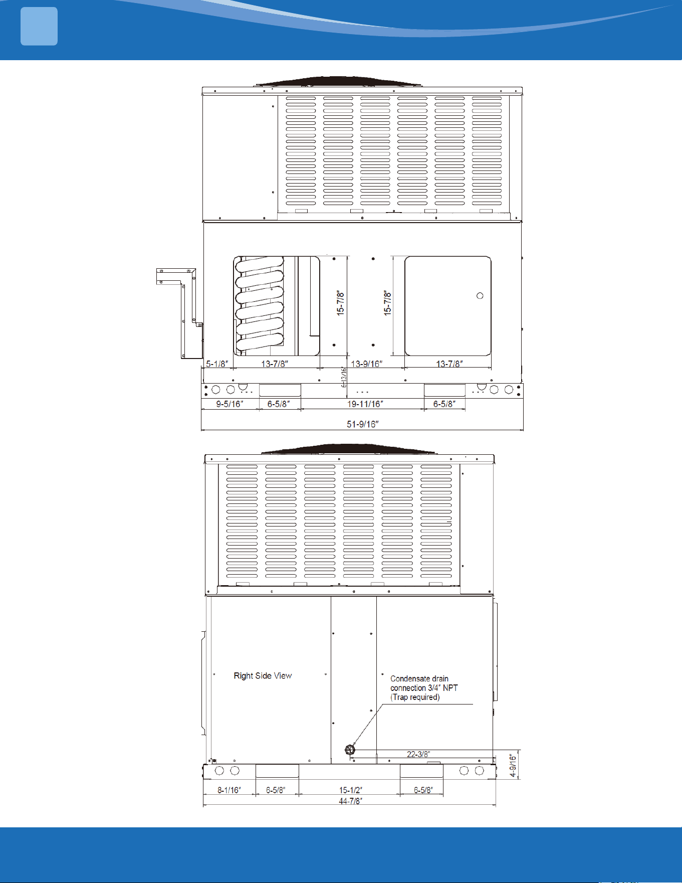
Figure 2.2b-
Dimensions Back and
Bottom
*The above
gures are
for reference
purposes only.
UNIT OVERVIEW
2
mrcool.com 10
10
*The above
gures are
for reference
purposes only.
MPG48S090M413B, MPG60S110M413B
Figure 2.3c-
Unit Dimensions
*The above
gures are
for reference
purposes only.
UNIT OVERVIEW
2
mrcool.com11
Figure 2.4d-
Dimensions Back &
Bottom
*The above
gures are
for reference
purposes only.
UNIT OVERVIEW
2
mrcool.com 12
12
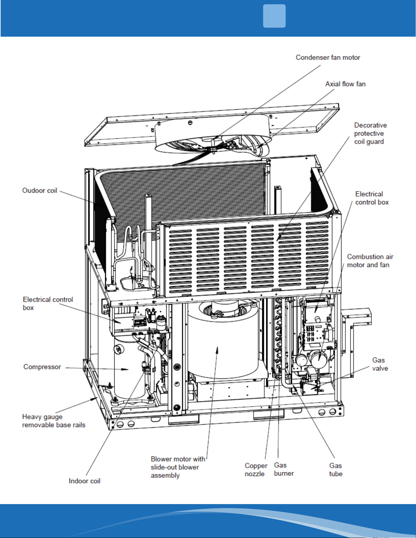
MPG24S060M413B, MPG30S060M413B, MPG36S090M413B, MPG42S090M413B
Figure 2.5a-
Component Location
*The above gure
is for reference
purposes only.
UNIT OVERVIEW
2

mrcool.com13
MPG48S090M413B, MPG60S110M413B
Figure 2.6b-
Component Location
*The above gure
is for reference
purposes only.
UNIT OVERVIEW
2

mrcool.com 14
14
INSTALLATION
3
3.1 Pre-Installation Checkpoints
Before installation, carefully check the following:
1. For rooftop installation, be sure the structure has enough strength to support the weight of unit.
2. Clearances and provision for servicing.
3. Power supply and wiring.
4. Gas supply and piping.
5. Air duct connections and sizing.
6. Drain facilities and connections.
7. Location for minimum noise and vibration.
8. The blue pearl cottons are for transportation protection and needs to be taken out.
3.2 Location Considerations
The metal parts of the unit may be subject to rust or deterioration in adverse environmental conditions. This
oxidation could shorten the equipment’s useful life. Salt spray, fog or mist in seacoast areas, sulfur or chlorine from
lawn watering systems, and various chemical contaminants from industries such as paper mills and petroleum
reneries are especially corrosive.
If the unit is to be installed in an area where contaminants are likely to be a problem, give special attention to the
equipment location and exposure:
1. Avoid having lawn sprinkler heads spray directly on the unit cabinet.
2. In coastal areas locate the unit on the side of the building away from the waterfront.
WARNING
• Disconnect all power to the unit before starting maintenance.
• Failure to do so can cause electrical shock resulting in personal injury or death.
3. Shielding by a fence or shrubs may give some protection.
4. Elevate the unit o its slab or base enough to allow air circulation and avoid holding water against the base
pan.
5. Frequent washing of the cabinet, fan blade and coil with fresh water will remove most of the salt or other
contaminants that build up on the unit.
6. Regular cleaning and waxing of the cabinet with a good automobile polish will provide some protection.
Several dierent types of protective coatings are oered in some areas. These coatings may provide some benet,
but the eectiveness of such coating materials cannot be veried by the equipment manufacturer. The best
protection is frequent cleaning, maintenance and minimal exposure to contaminants.
3.3 Outside Installation
WARNING
• This unit is designed certied for outdoor installation only.
• Installation inside any part of a structure can result in inadequate unit performance as well
as property damage. Installation inside can also cause recirculation of ue products into the
conditioned space resulting in personal injury or death.

mrcool.com15
INSTALLATION
3
3.4 Attaching Exhaust & Combustion Air Inlet Hoods
Do not operate this unit without the exhaust and combustion air inlet hood property installed. These hoods are
shipped in a carton in the return air compartment inside the unit and must be attached the unit is installed.
To attach exhaust and combustion air inlet hood:
1. Remove 3 screws securing lter access panel and remove lter access panel.
2. Remove both exhaust and combustion air inlet hoods from their carton, located inside the return air
compartment.
3. Attach lter access panel.
4. Attach the combustion air inlet hood and the exhaust hood with 4 and 6 screws. Screws are in parts bag
shipped in the burner compartment.
5. Vent the unit using the ue exhaust hood, as supplied from the factory, without alteration addition. The only
exception is with factory approved additions. Consult your local unity or other authority having jurisdiction for
accepted venting techniques.
3.5 Cover Panel Installation / Conversion Procedure
All unit sizes have return and discharge openings for both horizontal and downow congurations, and are factory
shipped with all downow duct openings covered, HORIZONTAL is factory shipped.
HORIZONTAL TO DOWNFLOW
1. Remove screws and covers from the supply and return bottom section.
2. Install gasket (supplied with parts bag) around perimeter of cover on the insulate side.
3. Secure covers to the side of the unit using existing screws and those supplied in the parts bag.
4. Seal duct covers with silicone caulk.
DOWNFLOW TO HORIZONTAL
1. Remove screws and covers from the supply and return bottom section.
2. Install gasket (factory shipped) around perimeter of cover on the insulate side.
3. Secure covers to the bottom of the unit using existing screws and those supplied in the parts bag.
1. Select a location where external water drainage cannot collect around unit.
2. Locate unit where operating sounds will not disturb owner or neighbors.
3. The location of the unit should allow proper access for inspection and servicing.
4. Locate unit so roof runo water does not pour directly on the unit. Provide gutter or other shielding at roof
level. Do not place unit in an area where excessive snow drifting may occur or accumulate.
5. Provide a concrete slab extending 3″ beyond all four sides of the unit. The slab should be suciently high
enough above grade to prevent surface water from entering the unit. The slab should be isolated from the
foundation wall.
6. Pitch the slab approximately 1/2″ so that the unit will be pitched toward the drain.
7. It is essential that the unit be elevated above the base pad to allow for defrost water runo, condensate
drainage, and possible refreezing or condensate. Route condensation o the base pad to an area that will not
become slippery and result in personal injury. Important: Do not interfere with opening in bottom of unit.
8. Where snowfall is anticipated, the height of the unit above the ground level must be considered. Mount unit
high enough to be above average area snowfall to prevent snow from blocking the outdoor coil, to allow
condensate runo, and to allow combustion air to enter the combustion air inlet.
mrcool.com 16
16
INSTALLATION
3
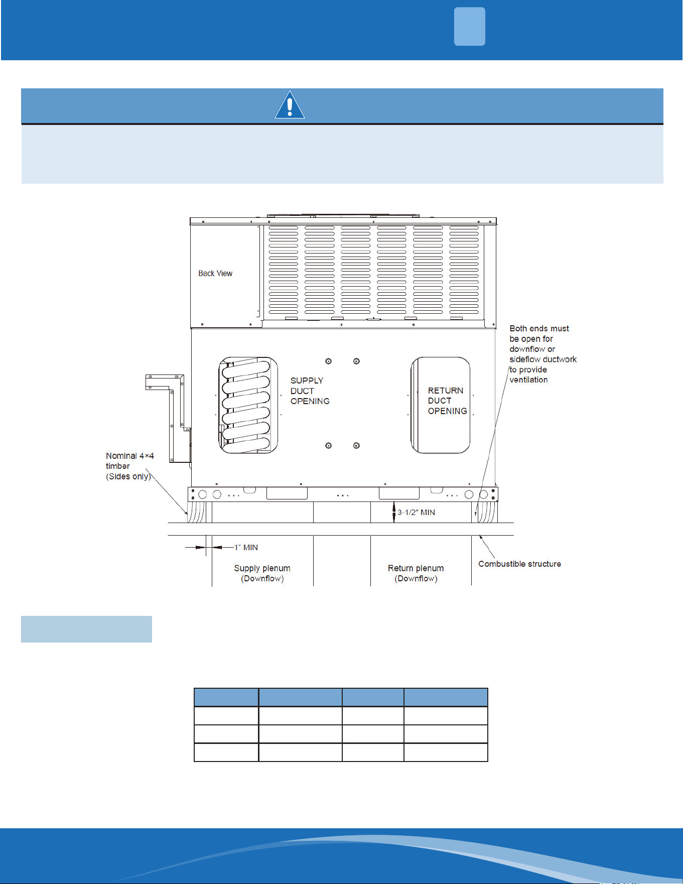
WARNING
• This unit must not be installed directly on wood ooring, Class A, Class B or Class C roof covering
materials, or any other combustion structure except as specied in these instructions. Failure to
adhere to this warning can cause a re or explosion resulting in property damage, personal injury
or death.
*The above gure is for reference purposes only.
Figure 3.5-
Exception to non-
combustible ooring
requirement
3.6 Clearance
All units require certain clearance for proper operation and service.
Refer to the following table for the minimum clearances required for construction, servicing, and proper unit
operation.
Direction Distance (in.) Direction Distance (in.)
Top
1
60 Right 24
Front 48 Left 12
4
Rear 18
2
Bottom
3
0
Table 3.6-
Unit Clearance
Duct clearance: 1 inch clearance for all sides of air supply duct.
1. Units must be installed outdoors. Over hanging structure or shrubs should not obscure condenser air discharge
outlet.
mrcool.com17
INSTALLATION
3
NOTE
For units applied with a roof curb, the minimum clearance may be reduced from 1 inch to 1/2 inch between
combustible roof curb material and this supply air duct.
3.7 Rigging & Handling
Exercise care when moving the unit. Do not remove any packaging until the unit is near the place of installation.
Rig the unit by attaching chain or cable slings to the lifting holes provided in the base rails. Spreader bars, whose
length exceeds the largest dimension across the unit, MUST be used across the top of the unit.
CAUTION
Before lifting, make sure the unit weight is distributed equally on the rigging cables so it will lift evenly.
Units may be moved or lifted with a forklift. Slotted openings in the base rails are provided for this purpose.
CAUTION
All panels must be secured in place when the unit is lifted. The condenser coils should be protected from
rigging cable damage with plywood or other suitable material.
2. The minimum clearance without economizer/fresh air damper. For distance with Economizer/fresh air damper,
please refer to the relevant install requirement.
3. Units may be installed on combustible oors made from wood or class A, B or C roof covering materials.
4. If Economizer/fresh air damper is used, a 24″ minimum clearance is required on left side of unit.
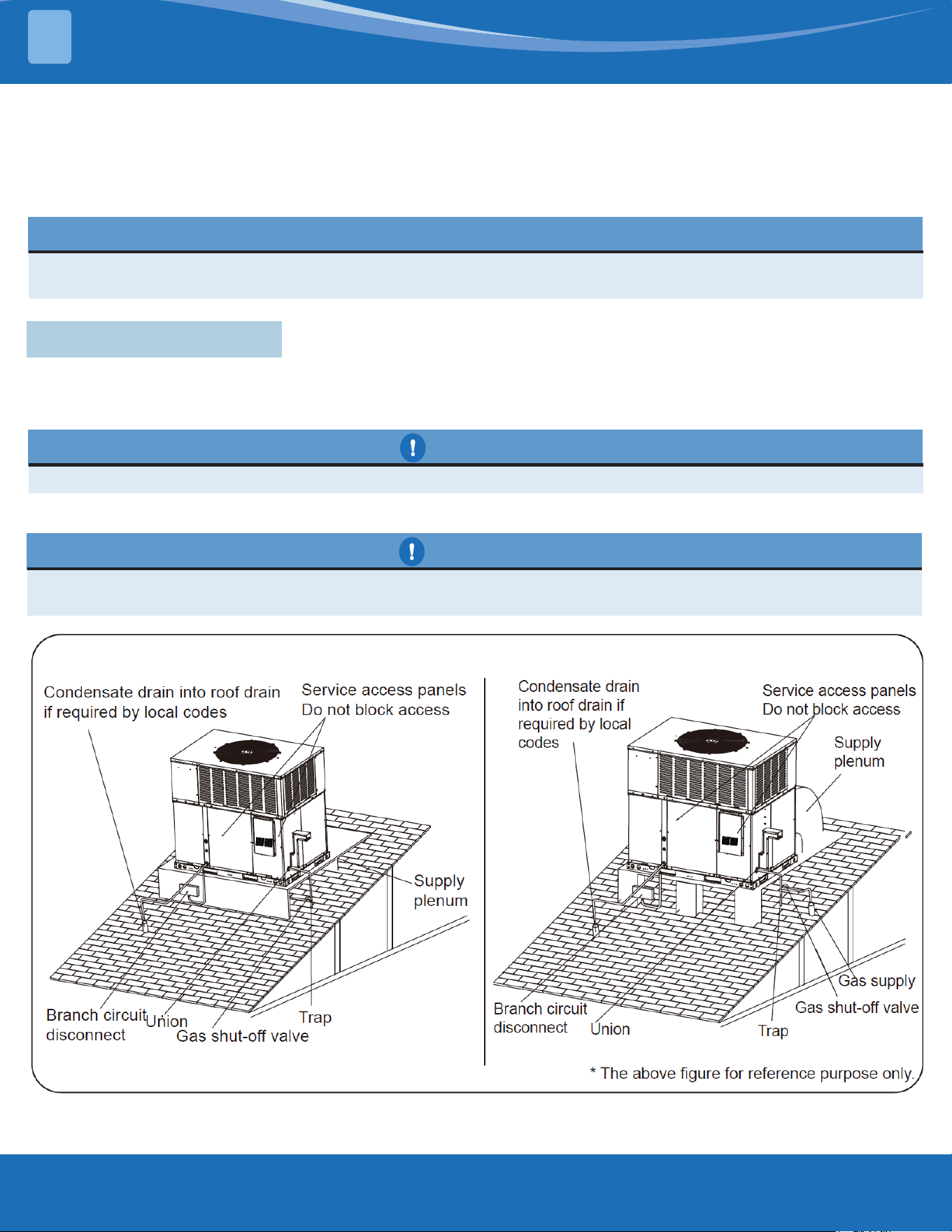
Figure 3.7a- Typical Installations
mrcool.com 18
18
INSTALLATION
3
Figure 3.7b-
Typical Installations
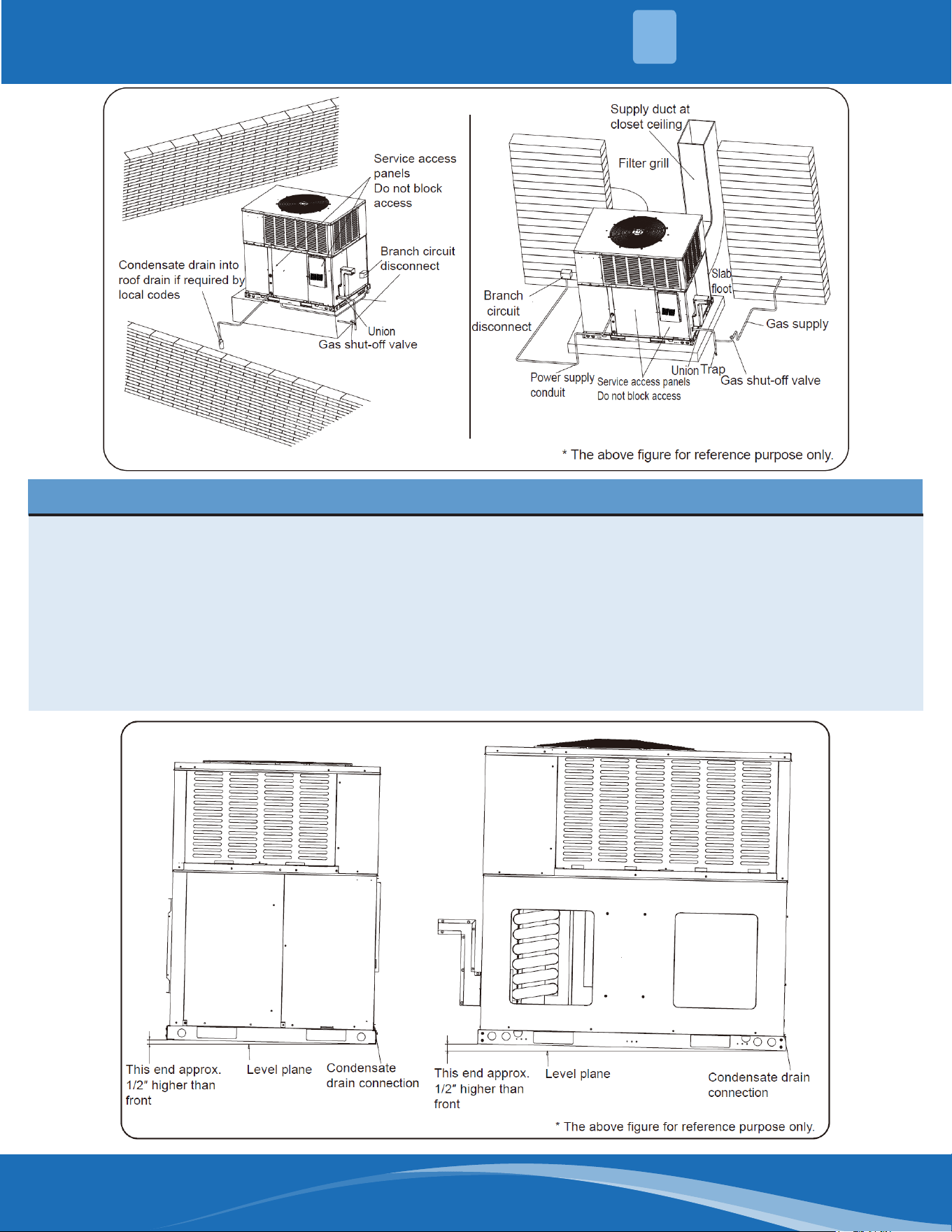
NOTE
A unit with electric heaters with an inlet or outlet duct that penetrates the building structure supporting the
unit shall be provided with a mounting base of noncombustible material so designed that, after the unit is
installed, there will be no open passages through the supporting structure that would permit ame or hot
gases from a re originating in the space below the supporting structure to travel to the space above that
structure. If the unit is intended to be installed on a supporting structure of combustible material, the base
shall be so designed that the required clearance will be maintained between the supporting structure and the
unit, plenum, and attached duct. Spacers necessary to provide required clearances shall be attached to the
unit mounting base, and shall extend not less than 76 mm (3 in.) below the upper surface of the supporting
structure, except that, in a unit designed for use only in a mobile home, the distance shall not be less than 19
mm (3/4 in.).
Figure 3.7c- Slab Installation
mrcool.com19
INSTALLATION
3
Table 3.8-
Unit
Clearance
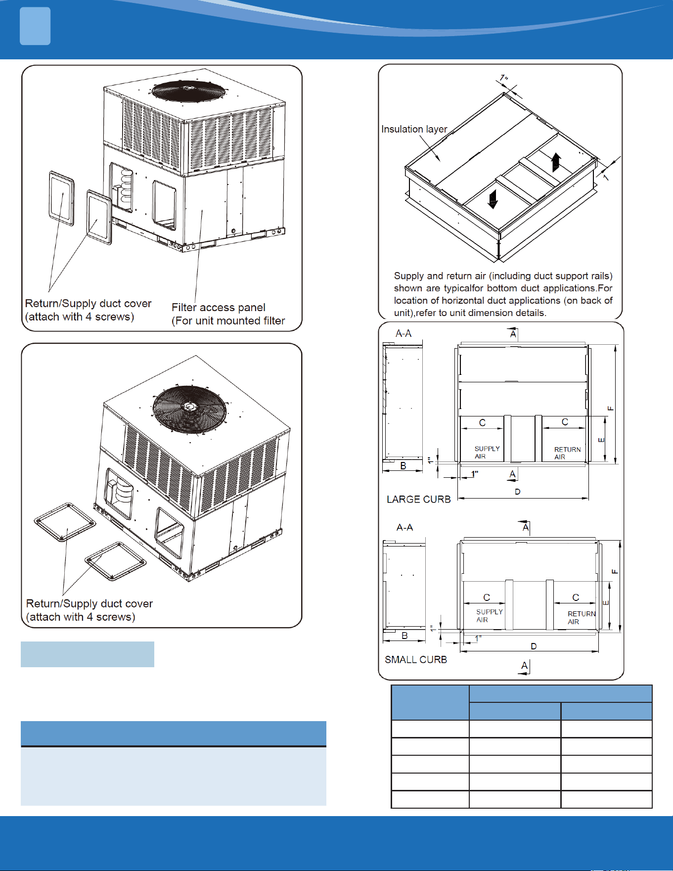
3.8 Roof Curb
In applications using roof curbs, the unit must be
placed on the curb so that the front of the unit is tightly
close to the curb. (See Fig. 3.8a- Roof Curb Dimension.)
NOTE
For units with a roof curb, the minimum clearance
may be reduced from 1 inch to 1/2 inch between
combustible roof curb material and this supply air
duct.
Dimensions
(In.)
Curb
Large Small
"B" in.[mm.] 14-1/4 [362] 14-1/4 [362]
"C" in.[mm.] 15-1/4 [387] 14 [356]
"D" in.[mm.] 46-1/16 [1170] 46-1/16 [1170]
"E" in.[mm.] 16 [406] 16 [406]
"F" in.[mm.] 42-3/16 [1070] 30-5/8 [778]
Figure 3.7d-
Duct cover
installation
side mounting
Figure 3.7e- Duct cover
installation base pan
mounting
Figure 3.8a-
Roof Curb Dimension
Figure 3.8b

mrcool.com 20
20
GAS SUPPLY, CONDENSATE DRAIN, & PIPING
4
3.9 Ductwork
Ductwork should be made and sized by installed and in accordance with Air Manual from Conditioning Contractors
of America and local codes.
NOTE
On ductwork exposed to outside air conditioning space, use at least 2" of insulation and a vapor barrier.
Flexible joint may be used to reduce noise.
These units are adaptable to horizontal use as well as rear supply and return air duct openings. To convert to
downow, use the steps is shown in 3.5.
A closed return duct system shall be used. This shall not preclude use of economizers or ventilation air intake.
Flexible joints may be used in the supply and return duct work to minimize the transmission of noise.
CAUTION
When fastening duct work to the side duct anges on the unit, insert the screws through the duct anges only.
DO NOT insert the screws through the casing. Outdoor duct work must be insulation and waterproofed.
3.10 Return Air
The installer must install eld supplied lters in the return air duct. A eld installed lter grille is\ recommended
for easy and convenient access to the lters for periodic inspection and cleaning. Filters must have adequate face
area for the rated air quantity of the unit. See air delivery tables for recommended lter size.
WARNING
Never allow products of combustion to the ue products to enter the return air ductwork, or the
circulating air supply.
All return ductwork must be adequately sealed and secured to the furnace with sheet metal screws,
and joints taped. All other duct joints must be secured with approved connections and sealed airtight.
Failure to prevent products of combustion from being circulated into the living space can create
potentially hazardous conditions, including carbon monoxide poisoning that could result in personal
injury or death.
3.11 Filters
IMPORTANT: Connect this unit only to gas supplied by a commercial utility.
1. Install gas piping in accordance with local codes and regulations of the local utility company. In the absence of
local codes, the installation must conform to the specications of the National Fuel Gas Code, ANSI Z223.1 - latest
edition.
4.1 Gas Connection
NOTE
The use of exible gas connectors is not permitted. If local codes allow the use of a corrugated stainless
steel exible gas appliance connector, always use a new listed connector. Do not use a connector which has
previously serviced another gas appliance.
NOTE
The Commonwealth of Massachusetts requires the gas shut-o valve to be a T-handle gas cock.
mrcool.com21
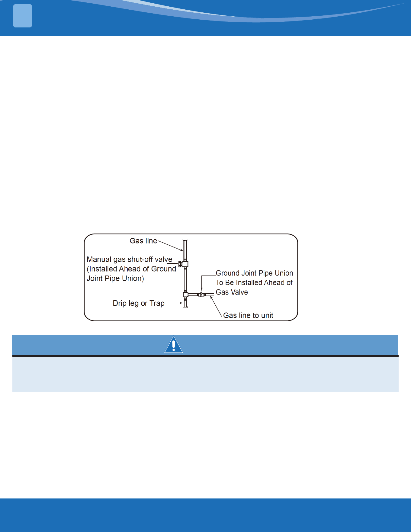
2. Connect the gas line to the gas pipe inlet opening provided into the 1/2″ inlet valve. See Fig. 4-1 for
typical piping.
3. Size the gas line to the furnace adequate enough to prevent undue pressure drop and never less than 1/2″
nominal pipe size.
4. Install a drip leg or sediment trap in the gas supply line as close to the unit as possible.
5. Install an outside ground joint union to connect the gas supply to the control assembly at the burner tray,
Unions may not be installed inside the unit.
6. Gas valves have been factory installed. Install a manual gas valve where local codes specify a shut-o valve
outside the unit casting.
7. Make sure piping is tight. A pipe compound resistant to the action of liqueed petroleum gases must be used
at all threaded pipe connections.
8. IMPORTANT: Any additions, changes or conversions required for the furnace to satisfactorily meet the application
should be made by a qualied installer, service agency or the gas supplier, using factory-specied or approved
parts. In the commonwealth of Massachusetts, installation must be performed by a licensed plumber or gas tter
for appropriate fuel.
IMPORTANT: Disconnect the furnace and its individual shuto valve the gas supply piping during any pressure
testing of that system at test pressures in excess of 1/2 psig or isolate the system from the gas supply piping
system by closing its individual manual shuto valve during any pressures equal to or less than 1/2 psig.
Figure 4.1-
Typical Gas Pipe
Arrangement
WARNING
Failure to follow the safety warnings exactly could result in serious injury, death of property damage.
Never test for gas leaks with an open ame. Use a commercially available soap solution made
specically for the detection of leaks to check all connections. A re or explosion may result causing
property damage, personal injury or loss of life.
TO CHECK FOR GAS LEAKS, USE A SOAP AND WATER SOLUTION OR OTHER APPROVED METHOD. DO NOT USE
AN OPEN FLAME.
IMPORTANT: Check the rating plate to make certain the appliance is equipped to burn the type of gas supplied.
Care should be taken after installation of this equipment that the gas control valve not be subjected to high gas
supply the pressure. In making gas connections, avoid strains as they may cause noise and damage the controls.
A backup wrench is required to be used on the valve to avoid damage.
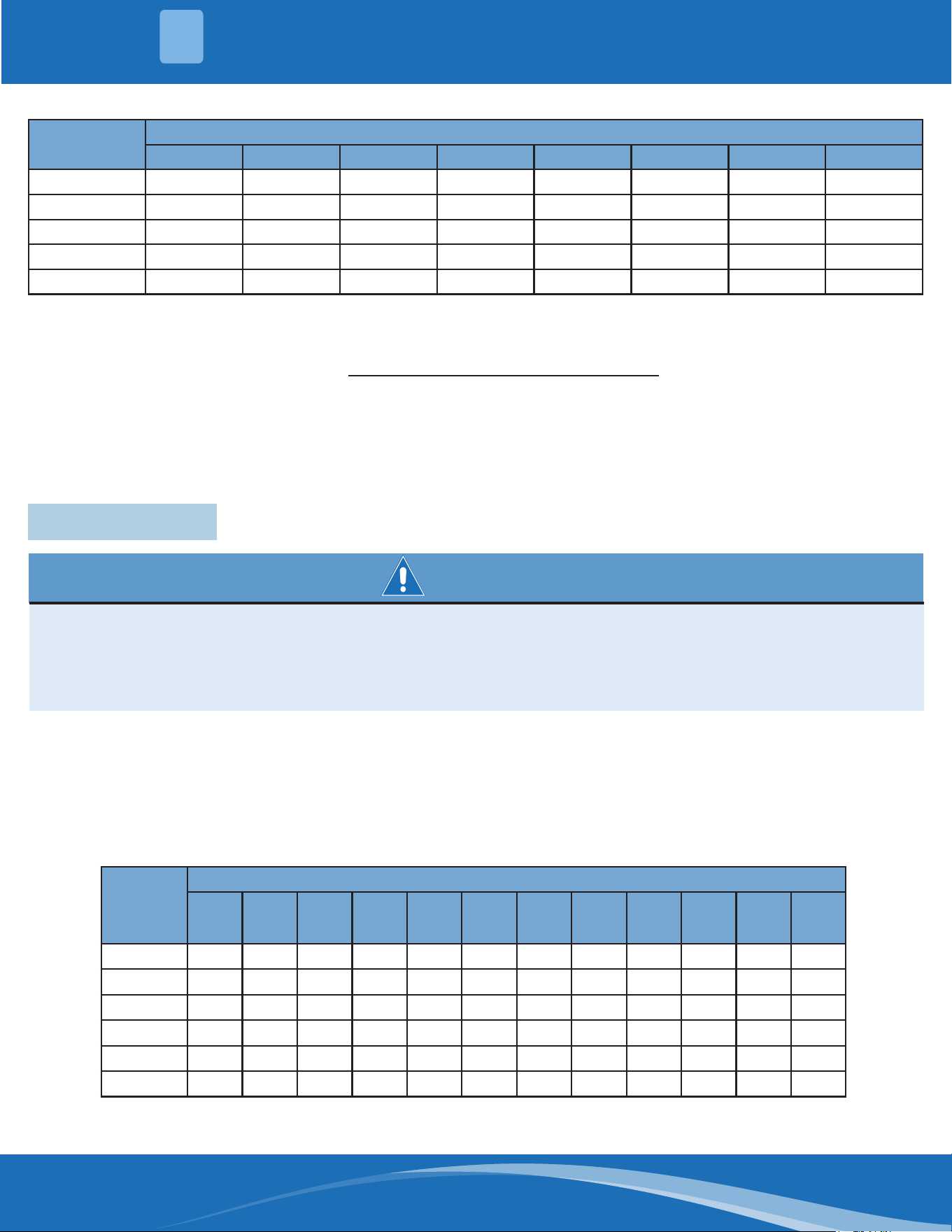
The capacity of gas pipe of dierent diameters and lengths in CFH with pressure drop of 0.5 in. and specic gravity
of 0.60 (natural gas) are shown in Table 4.1.
GAS SUPPLY, CONDENSATE DRAIN, & PIPING
4
mrcool.com 22
22
Nominal Iron
Pipe Size (in.)
Equivalent Length of Pipe (ft.)
10 20 30 40 50 60 70 80
1/2 132 92 73 63 56 50 46 53
3/4 278 190 152 130 115 105 95 90
1 520 350 285 245 215 195 180 170
1-1/4 1050 730 590 500 440 400 370 350
1-1/2 1600 1100 890 760 670 610 560 530
After determining the pipe length, select the pipe size which will provide the minimum cubic feet per hour required
for the gas input rating of the furnace. By formula:
CFH=
Furnace Input (Btu/h)
Heating Value of Gas (Btu/Cubic Foot)
The gas input of the furnace is marked on the furnace rating plate.
The heating value of the gas (Btu/Cubic Ft.) may be determined by consulting the local natural gas utility or the
L.P. gas supplier.
4.2 Conversion
WARNING
This unit is equipped at the factory for use on Natural Gas only.
Conversion to LP Gas requires a special kit which is included with the unit. DO NOT BURN ANY LIQUID
FUEL OR SOLID FUEL IN THIS UNIT. Burning any unapproved fuel will result in damage to this unit heat
exchanger, which could result in re, Carbon Monoxide poisoning, explosion, personal injury, property
damage or death.
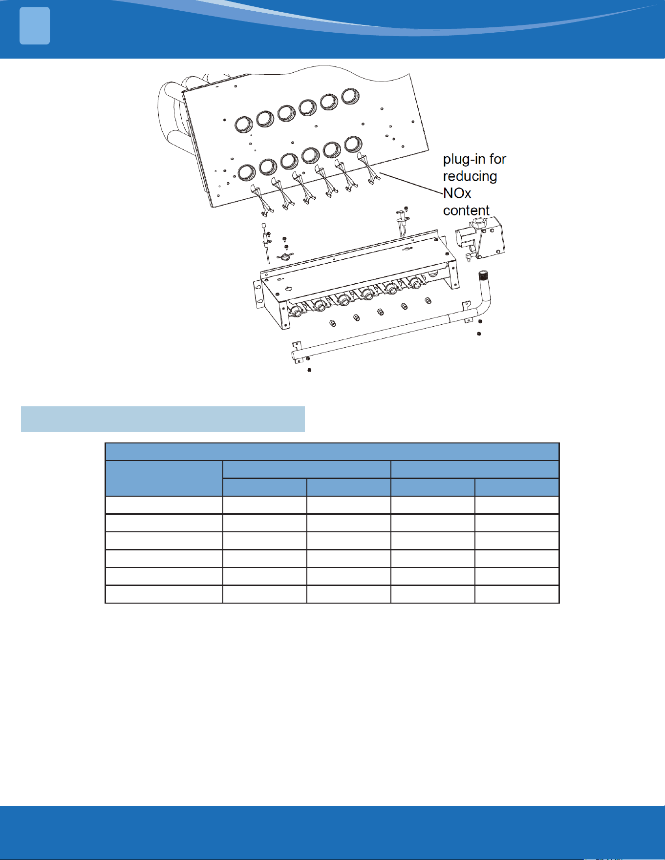
Convert the valve to use liqueed petroleum (LP) gas by replacing the pressure regulator spring with the conversion
kit spring. This LP kit spring allows the regulator to maintain the proper manifold pressure for LP gas. The correct
burner LP orices are included in the kit.
NOTE: The LP conversion kit is included with the unit. See Conversion Kit Index shipped with unit for proper
LP kit number. Furnace conversion to LP gas must be performed by a qualied technician.
Nominal
Iron
Pipe
Size (in.)
Equivalent Length of Pipe (ft.)
10 20 30 40 50 60 70 80 90 100 125 150
1/2 275 189 152 129 114 103 96 89 83 78 69 63
3/4 567 393 315 267 237 217 196 182 173 162 146 132
1 1071 732 590 504 448 409 378 346 322 307 275 252
1-1/4 2205 1496 1212 1039 913 834 771 724 677 630 567 511
1-1/2 3307 2299 1858 1559 1417 1275 1181 1086 1023 976 866 787
2 6221 4331 3465 2992 2646 2394 2205 2047 1921 1811 1606 1496
Example (LP): Input BTU requirement of unit, 150000 Equivalent length of pipe, 60 ft. = 3/4" IPS
Table 4.1: Natural Gas Pipe Capacity Table (CFH-Cubic Feet of Gas per hour)
Table 4.2: LP Gas Pipe Capacity Table (CFH-Cubic Feet of Gas per hour)
GAS SUPPLY, CONDENSATE DRAIN, & PIPING
4
mrcool.com23
*The above gure is for reference purposes
only.
Fig. 4.2: Burner & Gas Valve Arrangement
Supply and manifold pressure taps are located on the gas valve body 1/8″ N.P.T.
Use a properly calibrated manometer gauge for accurate gas pressure readings.
Only small variations in the gas ow should be made by means of the pressure regulator adjustment. Furnaces
functioning on LP gas must be set by means of the tank or branch supply regulators. The furnace outlet pressure
should be set at 10″ W.C. at the gas control valve.
To adjust the pressure regulator, remove the regulator cap and turn the adjustment screw clockwise to increase
pressure or counterclockwise to decrease pressure. Then replace the regulator cap securely. Any necessary major
changes in the gas ow rate should be made by changing the size of the burner orices. To change orice spuds,
shut o the manual main gas valve and remove the gas manifold.
For elevations up to 2000 feet, rating plate input rating apply. For high altitudes (elevations over 2000 feet), see
conversion kit index for derating and orice spud sizes.
4.3 Adjusting or Checking Furnace Input
Manifold Gas Pressure
Model
Range Orice
Natural Gas Propane Gas Natural Gas Propane Gas
MPG24S060M413B 3.1" W.C. 9.6" W.C. 51 59
MPG30S060M413B 3.1" W.C. 9.6" W.C. 51 59
MPG36S090M413B 3.2" W.C. 10.5" W.C. 51 59
MPG42S090M413B 3.2" W.C. 10.5" W.C. 51 59
MPG48S090M413B 3.3" W.C. 9.5" W.C. 49 56
MPG60S110M413B 3.45" W.C. 10.0" W.C. 49 56
GAS SUPPLY, CONDENSATE DRAIN, & PIPING
4
Table 4.3-
Manifold Gas
Pressure
mrcool.com 24
24
WIRING
5
Check of input is important to prevent over-ring of the furnace beyond its designated input, NEVER SET
INPUT ABOVE THAT SHOWN ON THE RATING PLATE. Use the following formula to determine input rate.
C.F.H.
Required
Heating Value of Gas (BTU/Cubic ft.) x3600
Time of Seconds (for 1 Cubic ft.) of gas
=
Start the furnace and measure the time required to burn on cubic foot of gas. Prior to checking the furnace input,
make certain that all other gas appliances are shut o, with the exception of pilot burners. Time the meter with
only the furnace in operation.
IMPORTANT NOTE FOR ALL ALTITUDES ABOVE 2000 FEET: The main burner orices in your furnace and in these
kits are sized for the nameplate input and intended for installations at elevations up to 2000 feet in the USA or
Canada, or for elevations of 2000-4500 feet in Canada if the unit has been derated at the factory. For elevations
above 2000 feet IN THE USA ONLY (see ANSI-Z223.1), the burner orices must be sized to reduce the input 4% for
each 1000 feet above sea level.
NOTICE: Derating of the heating input for high altitude in the eld is unlawful in Canada (refer to CAN/CGA 2.17).
Units installed in altitudes greater than 2000 feet must be shipped from the factory or from a factory authorized
conversion station with the heating input derated by 10% so as to operate properly in altitudes from 2000-4500
feet.
The evaporator coil condensate drain ends with a threaded 3/4″ nominal PVC stub. A trap is built in for proper
condensate drainage and to prevent debris from being drawn into the unit. Do not connect the drain to a closed
sewer line. It is recommended that a PVC cement not be used so that the drain line can be easily cleaned in the
future.
IMPORTANT: Do not install an external trap. Doing so can cause improper drainage of the condensate and result
in ooding within the unit.
4.4 Condensate Drain
5.1 Power Supply
WARNING
Turn o the main electrical power at the branch circuit disconnect closest to the unit before
attempting any wiring. Failure to do so can cause electrical shock resulting in personal injury or death.
1. All wiring should be made in accordance with the National Electrical Code. Consult the local power company
to determine the availability of sucient power to operate the unit. Check the voltage at power supply to
make sure it corresponds to the unit’s rated voltage requirement. Install a branch circuit disconnect near the
rooftop, in accordance with the N.E.C., C.E.C. or local codes.
2. It is important that proper electrical power is available at the unit. Voltage should not vary more than 10%
from that stamped on the unit nameplate. On three phase units, phases must be balanced within 3%.
3. For branch circuit wiring (main power supply to unit disconnect), the minimum wire size for the length of run
can be determined from Table 5-1 using the circuit ampacity found on the unit rating plate. Use the smallest
wire size allowable in Table 5-1 from the disconnect to unit. The disconnect must be in sight and readily
accessible of the unit.
mrcool.com25
Branch Circuit Ampacity
15 20 25 30 35 40 45 50
Supply
Wire
Length
(ft.)
200 6 4 4 4 3 3 2 2
150 8 6 6 4 4 4 3 3
100 10 8 8 6 6 6 4 4
50 14 12 10 10 8 8 6 6
Table 5.1a- Branch Circuit Copper Wire Size (in.)
NOTES:
1. Wire size based on 60°C rated wire insulation and 30°C Ambient Temp.
2. For more than 3 conductors in a raceway or cable, see the N.E.C. for derating the ampacity of each conductor.
When installed, the unit must be electrically grounded in accordance with local codes or, in the absence of
local codes, with the National Electrical Code, ANSI/NFPA 70, if an external electrical source is utilized.
IMPORTANT: This unit is approved for use with copper conductors only connected to unit contactor.
Warranty may be jeopardized if aluminum wire is connected to unit contactor.
Special instructions apply for power wiring aluminum conductors: Warranty is void if connections are not made
per instructions.
Attach a length (6″ or more) of recommended size copper wire to the unit contactor terminals L1 and L3 for single
phase.
Select the equivalent aluminum wire size from the table below:
Splice copper wire pigtails to aluminum wire with U.L. recognized connectors for copper-aluminum splices. Please
exercise the following instructions very carefully to obtain a positive and lasting connection:
1. Strip insulation from aluminum conductor.
2. Coat the stripped end of the aluminum wire with the recommended inhibitor, and wire brush the aluminum
surface through inhibitor.
3. INHIBITORS: Brundy-Pentex ”A”; Alcoa-No. 2EJC; T & B-KPOR Shield.
4. Clean and recoat aluminum conductor with inhibitor.
5. Make the splice using the below listed wire nuts or split bolt connectors.
6. Coat the entire connection with inhibitor and wrap with electrical insulating tape.
AWG Copper Wire Size AWG Aluminum Wire Size Connector Type & Size (or equivalent)
#12 #10 T & B Wire Nut PT2
#10 #8 T & B Wire Nut PT3
#8 #6 Sherman Split Bolt TSP6
#6 #4 Sherman Split Bolt TSP4
#4 #2 Sherman Split TSP2
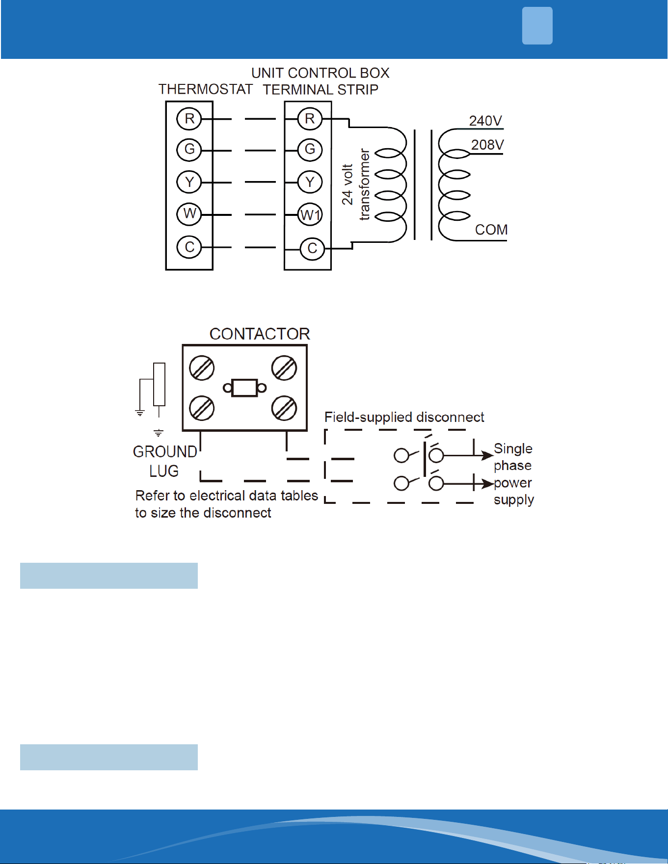
To wire unit, refer to the following Fig. 5-1.
Wiring to be done in the eld between the unit and devices not attached to the unit, or between separate devices
which are eld installed and located, shall conform with the temperature limitation for Type T wire [63°F rise]
when installed in accordance with the manufacturer’s instructions.
5.2 Hook-Up
WIRING
5
Table 5.1b- Aluminum Wire Sizes
mrcool.com 26
26
Fig, 5.2a - Typical Field Control Wiring Diagram
Fig. 5.2b - Typical Field Power Wiring Diagram
IMPORTANT: Some single phase units are equipped with a single pole contactor. Caution must be exercised when
servicing as only one leg of the power supply is broken with the contactor.
Some models are equipped with an electronically commutated blower motor which is constantly energized unless
the main unit disconnect is in the o position.
A diagram of the internal wiring of this unit is located under the electrical box cover and in this manual. If any of
the original wire as supplied with the appliance must be replaced, the wire gauge and insulation must be the same
as the original wiring.
Transformer is factory wired for 230 volt on 208/230 volt models and must be changed to 208 volt applications.
See unit wiring diagram for 208 volt wiring.
5.3 Internal Wiring
The room thermostat must be specically designed to control package gas electric units.
5.4 Thermostat
WIRING
5

mrcool.com27
FURNACE SECTION CONTROLS & IGNITION SYSTEM
6
1. This unit is equipped with an integrated direct spark ignition control.
2. The thermostat calls for gas heat.
3. The control board will run a self check to verify that the limit control and manual reset over temperature
control are closed and that the pressure switch is open. If so, the induced draft blower (inducer) begin a
prepurge cycle.
4. The air proving negative pressure switch closes.
5. 15 seconds after the pressure switch closes, the gas valve opens and the spark is initiated for a 7 second trial
for ignition.
6. Burners ignite and ame sensor proves all burners have lit.
7. The circulating air blower is energized after 45 seconds.
8. The control board enters a normal operation loop in which all safety controls are monitored continuously.
9. Thermostat is satised and opens.
10. The gas valve is de-energized and closes, shutting down the burner ame.
11. The control board will de-energized the inducer after a ve second post purge.
12. The circulating air blower BLOWER-LOW is de-energized after max. 90 seconds.
• The integrated control board has a three times ignition system.
• After a total of 3 trials for ignition without sensing main burner ame, the system goes into lockout mode.
• After 1 hour, the ignition control repeats the prepurge and ignition cycles for 3 tries and then goes into lockout
mode again.
• It continues this sequence of cycles and lockout each hour until ignition is successful or power is interrupted.
• During the lockout mode, neither the spark ignition control or gas valve will be energized until the system
is reset by turning the thermostat to the “OFF” position or interrupting the electrical power to the unit for 3
seconds or longer.
• The induced draft blower and main burner will shut o when the thermostat is satised.
• The circulating air blower will start and run on the heating speed if the thermostat fan switch is in the “ON”
position.
The integrated furnace control is equipped with diagnostic LED. The LED is lit continuously when there is power to
the control without a call for heat. If the LED is not lit, there is either no power to the control or there is an internal
component failure within the control, and the control should be replaced.
If the control detects the following failures, the LED will ash for designated failure detections.
2 Flash: Failed to detect or sustain ame,system locked out.
3 Flash: Pressure switch or induced draft blower problem detected.
4 Flash: High limit or auxiliary limit open.
5 Flash: Flame sensed and gas valve not energized or ame sensed with no “W” signal.
6 Flash: Over temperature switch open.
7 Flash: Thermostat miswired; W1 and W2 swapped. Slow ash rate: Normal,call for heat.
6.1 Normal Furnace Operating Sequence
This appliance is equipped with a direct spark intermittent ignition device. This device lights the main burners
each time the room thermostat (closes) calls for gas heat. See operating instructions on the back of the furnace/
controls access panel.
6.2 Operating Instructions

mrcool.com 28
28
WARNING
Do not attempt to manually light this furnace with a match or any open ame. Attempting to do so can
cause an explosion or re resulting in property damage, personal injury or death.
1. Set the thermostat to its lowest setting.
2. Turn o all electric power to the appliance.
3. This appliance does not have a pilot. It is equipped with an ignition device which automatically lights the
burner. Do not try to light the burner by hand.
4. Remove control door.
5. Turn the gas valve to the “OFF” position.
6. Wait ve (5) minutes to clear out any gas. Then smell for gas, including near the oor. If you smell gas, STOP!
Follow B in the safety information on the Operating Instructions located on the back of the controls/access
panel. If you don’t smell gas, go to the next step.
7. Turn the gas valve to the “ON” position.
8. Replace the control door.
9. Turn on all electric power to the appliance.
10. Set the thermostat to the desired setting.
11. If the appliance will not operate, follow the instructions below to shut down the furnace.
6.3 Starting the Furnace
WARNING
The spark igniter and ignition lead from the ignition control are high voltage. Keep hands or tools away
to prevent electrical shock. Shut o electrical power before servicing any of the controls. Failure to
adhere to this warning can result in personal injury or death.
The initial start-up on a new installation may require the control system to be energized in some time until any air
has bled through the system and fuel gas is available at the burners.
1. Set the thermostat to the lowest setting.
2. Turn o all electric power to the appliance if service is to be performed.
3. Remove control door.
4. Move gas valve to the“OFF”position.
5. Replace control door.
6.4 Shutting Down the Furnace
WARNING
Should overheating occur or the gas supply fail to shut o. Shut o the Manual Gas valve to the
appliance before shutting o the electrical supply. Failure to do so can result in an explosion or re
causing property damage, severe personal injury or death.
FURNACE SECTION CONTROLS & IGNITION SYSTEM
6

mrcool.com29
SYSTEM OPERATING INFORMATION
7
Burners for these units have been designed so that eld adjustment is not required. Burners are tray-mounted
and accessible for easy cleaning when required.
6.5 Burners
A manual reset over temperature control is located on the burner shield. This device senses blockage in the heat
exchanger or insucient combustion air. This shuts o the main burners if excessive temperatures occur in the
burner compartment.
Operation of this control indicates an abnormal condition. Therefore, the unit should be examined by a qualied
installer, service agency, or the gas supplier before being placed back into operation.
6.6 Manual Reset Over Temperature Control
WARNING
DO NOT JUMPER THIS DEVICE! Do not reset the over temperature control without taking corrective
action to assure that an adequate supply of combustion air is maintained under all conditions of
operation. Failure to do so can result in Carbon Monoxide poisoning or death. Replace this control only
with the identical replacement part.
This furnace has a negative pressure switch for sensing a blocked exhaust or a failed induced draft blower. It is
normally closed when the induced draft blower starts, indicating air ow through the combustion chamber.
6.7 Pressure Switch
The supply air high temperature limit cut-o is set at the factory and cannot be adjusted. It is calibrated to prevent
the air temperature leaving the furnace from exceeding the maximum outlet air temperature. WARNING: DO
NOT JUMPER THIS DEVICE! Replace this control only with the identical replacement part.
6.8 Limit Control
Advise the homeowner of the following:
1. Keep the air lters clean. The heating system operates better, more eciently and more economically.
2. Arrange the furniture and drapes so that the supply air registers and the return air grilles are unobstructed.
3. Close doors and windows. This reduces the heating load on the system.
4. Avoid excessive use of exhaust fans.
5. Do not permit the heat generated by television, lamps or radios to inuence the thermostat operation.
6. Except for the mounting platform, keep all combustible articles three feet from the unit and exhaust system.
7. IMPORTANT: Replace all blower doors and compartment after servicing the unit. Do not operate the unit
without all panels and doors securely in place.
8. Do not allow snow or other debris to accumulate in the vicinity of the appliance.
7.1 User Reminders
The unit’s furnace should operate for many years without excessive scale build-up in ue passageways; and
it should have a qualied installer, service agency, or gas supplier annually inspect the ue passageways, the
exhaust system and the burners for continued safe operation, paying particular attention to deterioration from
corrosion or other sources.
7.2 Furnace Section Maintenance
mrcool.com 30
30
If during inspection the ue passageways and exhaust system are determined to require cleaning, the following
procedures should be followed (by a qualied installer, service agency, or gas supplier)
1. Turn o the electrical power to the unit and set the thermostat to the lowest temperature.
2. Shut o the gas supply to the unit either at the meter or at manual valve in the supply piping.
WARNING
Label all wires prior to disconnection when servicing controls. Wiring errors can cause improper and
dangerous operation resulting in re ,electrical shock, property damage, personal injury or death.
3. Remove the furnace controls access panel and the control box cover.
4. Disconnect the gas supply piping from the gas valve.
5. Disconnect the wiring to the induced draft blower motor, gas valve, ame sensor, and ame roll-out control,
and igniter cable. Mark all wires disconnected for proper reconnection.
6. Remove the screws (4) connecting the burner tray to the heat exchanger mounting panel.
7. Remove the burner tray and the manifold assembly from the unit.
8. Remove the screws (4) connecting the induced draft blower to the collector box and screws (16) connecting
the collector box to the heat exchanger mounting panel. Remove the induced draft blower and the collector
box from the unit.
9. Remove the turbulators from inside the heat exchangers by inserting the blade of a screwdriver under the
locking tabs. Pop the tabs out of the expanded grooves of the heat exchanger. Slide the turbulators out of the
heat exchangers.
10. Direct a water hose into the outlet of the heat exchanger top. Flush the inside of each heat exchanger tube
with water. Blow out each tube with air to remove excessive moisture.
11. Reassemble (steps 1 through 10 in reverse order).
Be careful not to strip out the screw holes used to mount the collector box and inducer blower. Replace
inducer blower gasket and collector box gasket with factory replacements if damaged.
WARNING
Holes in the exhaust transition or heat exchanger can cause toxic fumes to enter the home. The
exhaust transition or heat exchanger must be replaced if they have holes or cracks in them. Failure to
do so can cause Carbon Monoxide poisoning resulting in personal injury or death.
The manufacturer recommends that a qualied installer, service agency or the gas suppler visually inspect the
burner ames for the desired ame appearance at the beginning of the heating season and approximately midway
in heating season.
The manufacturer also recommends that a qualied installer, service agency or the gas supplier clean the ame
sensor with steel wool at the beginning of the heating season.
WARNING
Disconnect main electrical power to the unit before attempting maintenance. Failure to do so may
result in electrical shock or severe personal injury or death.
SYSTEM OPERATING INFORMATION
7

mrcool.com31
IMPORTANT: DO NOT attempt to lubricate the bearings on the blower motor or the induced draft blower
motor. Addition of lubricants can reduce the motor life and void the warranty.
The blower motor and induced draft blower motor are prelubricated by the manufacturer and do not require
further attention.
A qualied installer, service agency or the gas supplier must periodically clean the motors to prevent the possibility
of overheating due to an accumulation of dust and dirt on the windings or on the motor exterior. And, as suggested
elsewhere in these instruct ions, the air lters should be kept clean because dirty lters can restrict air ow and
the motor depends upon sucient air owing across and through it to prevent overheating.
7.3 Lubrication
It is recommended that at the beginning of each cooling season a qualied installer or service agency inspect and
clean the cooling section of this unit. The following areas should be addressed: evaporator coil, condenser coil,
condenser fan motor and venturi area.
To inspect the evaporator coil:
1. Remove the lter access panel and the blower/evaporator coil access panel.
7.4 Cooling Section Maintenance
WARNING
Label all wires prior to disconnection when servicing controls. Wiring errors can cause improper and
dangerous operation resulting in re, electrical shock, property damage, personal injury or death.
2. Unplug the wires from the circulating air blower and the limit control. Remove the two screws and slide the
blower out of the unit sideways.
3. Shine a ashlight on the evaporator coil (both sides) and inspect for accumulation of lint, insulation, etc.
4. If coil requires cleaning, follow the steps shown below.
Cleaning Condenser Coil:
1. Remove screws from condenser fan grille assembly and lay grille over on the unit top panel.
2. Remove the controls access panel and the control box cover.
3. Disconnect the outdoor fan motor wiring from the compressor contactor and capacitor. Remove the strain
relief in the bulkhead and pull the fan motor wires through. Set grille assembly to the side.
4. Remove the screws that secure the unit top to the unit. Remove the top and set the unit top to the side.
5. The coil should be cleaned when it is dry. If the coil is coated with dirt or lint, vacuum it with a soft brush
attachment. Be careful not to bend the coil ns.
6. The recommended cleaning method for microchannel condenser coils is pressurized water or air with an on-
pinpoint nozzle and an ECU of at least 180 with pressure no greater than 600psi. To minimize the risk of coil
damage, approach the cleaning of the coil with the pressure washer aimed perpendicular to the face of the coil
during cleaning. Optimum clearance between the sprayer nozzle and the microchannel coil is 1”–3”.
Cleaning Evaporator Coil, Drain Pan, Condensate Drain, Condenser Fan, Circulation Air Blower & Venturi:
Remove the screws from the lter access panel and the blower/evaporator coil access panel from the unit. Remove
the lter access panel and the blower/evaporator coil access panel.
The coil should be cleaned when it is dry. If the coil is coated with dirt or lint, vacuum it with a soft brush attachment.
Be careful not to bend the Coil ns.
If the coil is coated with oil or grease, clean it with a mild detergent-and-water solution. Rinse the coil thoroughly
with water.
IMPORTANT: Do not use excessive water pressure. Excessive water pressure can bend the tins and tubing of the
coil and lead to inadequate unit performance. Be careful not to splash water excessively into unit.
SYSTEM OPERATING INFORMATION
7

mrcool.com 32
32
Inspect the drain pan and condensate drain at the same time the evaporator coil is checked. Clean the drain pan
by ushing with water and removing any matters of obstructions which may be present.
Flush the drain tube with water. If the drain tube is blocked, it can usually be cleared with high pressure water.
The venturi should also be inspected for items of obstruction such as collections of grass, dirt or spider webs.
Remove any that are present.
Inspect the circulating air blower wheel and motor for accumulation of lint, dirt or other obstruction and clean if
necessary. Inspect the blower motor mounts and the blower housing for loose mounts or other damage. Repair
or replace if necessary.
Re-assembly:
1. Place the condenser coil protective grille back on unit and replace all screws.
2. Place top panel back on unit and replace all screws.
3. Set condenser fan grille assembly on top of the unit with the fan on top and the motor wires on the venturi
side. Run the fan motor wires through the bulkhead and pull wires through the hole on the bottom of the
control box on the left side and into the control box. Reconnect fan motor wires per the wiring diagram
attached to the back of the control box cover.
4. Replace wire strain relief in bulkhead after the slack is pulled out of the wires on the fan side. This will assure
wires will not be damaged by the fan during unit operation.
5. Turn the condenser fan grille assembly over and into the recess in the unit top. Secure the grille to the unit
with the four long #8 screws removed earlier.
6. Replace the circulating air blower, making sure that all wires are properly reconnected per the unit wiring
diagram.
7. Replace the lter and blower/evaporator coil access panels.
8. Replace the control box cover and controls access panel.
9. Restore electrical power to the unit and check for proper operation, especially the condenser fan motor.
Contact your local distributor for a complete parts list.
7.5 Replacement Parts
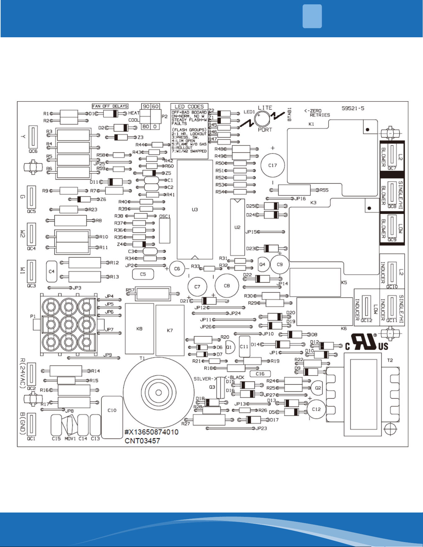
Refer to the appropriate wiring diagram included in this manual.
7.6 Wiring Diagrams
Refer to the appropriate charge chart included in this manual.
7.7 Charging
After determining necessary CFM and speed tap data, follow the steps below to change speeds.
1. Remove control door.
2. Please refer to the Table 10-1 & Table 10-2 and wiring diagram for the proper location of the wire on the speed
tap block of the indoor blower motor to obtain the speed you have chosen.
3. After adjusting the wires accordingly,replace control door.
7.8 Blower Motor Speed Taps
SYSTEM OPERATING INFORMATION
7
mrcool.com33
OPERATION
8
1. Heating mode
The wall thermostat “calls for heat,” closing the R--to--W circuit. The furnace control performs a “NORMAL FURNACE
OPERATING SEQUENCE”.
2.Cooling mode
In the cooling mode, The thermostat closes the R--to--G--and--Y circuits. The thermostat will energize the
compressor contactor and the indoor blower relay. The blower motor will operate on BLOWER-SINGLE/HI speed.
After the thermostat is satised, the compressor is de-energized and the cool mode delay-to-fan-o period begins.
After the delay-to-fan- o period ends, the circulator fan is de-energized. The indoor blower can be operated
continuously by setting the thermostat fan switch at the “ON” position.
3. Fan mode
When the circuit R--to--G is closed by the thermostat, the blower motor will operate on BLOWER-LOW speed , If
the thermostat fan switch is moved to the ON position, the circulator fan will be energized. When the fan switch
is returned to the AUTO position, the circulator fan will be de-energized.
8.1 Control System Operation
NOTE
Most single phase units are equipped with Permanent Split Capacitor (PSC) motors (no start relay or start
capacitor). It is important that such systems be o for a minimum of 5 minutes before restarting to allow
equalization of pressures. Do not move the thermostat to cycle unit without waiting ve minutes. To do so may
cause the compressor to stop on an automatic open overload device or blow a fuse. Poor electrical service can
cause nuisance tripping in overloads or blow fuses.
IMPORTANT: The compressor has an internal overload protector. Under some conditions, it can take up to 2
hours for this overload to reset. Make sure overload has had time to reset before condensing the compressor.
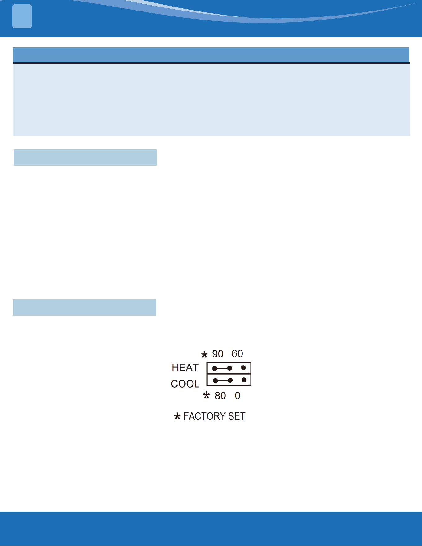
The control allows the blower to operate for up to 90 seconds after the thermostat is satised.
As shipped, the circulator blower fan will remain on for 90 seconds after the gas valve closes. When a call for
cooling occurs, the circulator fan comes on and remains on for 80 seconds after the call for cooling ends. During
normal heating operation, the circulator fan will come on approximately 45 seconds after the gas valve opens.
8.2 Fan Delay Adjustment
mrcool.com 34
34
OPERATION
8
mrcool.com35
SEER2 PHYSICAL DATA
9
Component Models
MPG24S060M413B MPG30S060M413B MPG36S090M413B
Nominal Tonnage 2.0 2.5 3.0
ARI Cooling
Performance
ARI Net Capacity (Btu) 22800 28400 34200
EER2 10.6 10.6 10.6
SEER2 13.4 13.4 13.4
Nominal CFM 720 940 1050
System Power (kW) 2.15 2.68 3.30
Refrigerant Type R410a R410a R410a
Refrigerant Charge (lb-oz) 3-0 3-5 3-5
Gas Heating
Performance
Heating Input (Btu) 60000 60000 90000
Heating Output (Btu) 48000 48000 72000
Temperature Rise Range (°F) 30-60 30-60 40-70
AFUE (%) 81 81 81
Steady State Eciency (%) 81 81 81
No. Burners 5 5 7
No. Stages 1 1 1
Gas Connection Pipe Size (in.) 1/2" NPT 1/2" NPT 1/2" NPT
Dimensions
(inches)
Length 50-11/16 50-11/16 50-11/16
Width 35-1/16 35-1/16 35-1/16
Height 46-13/16 46-13/16 46-13/16
Operating Weight (lbs) 428 437 443
Compressors Type Rotate Rotate Rotate
Quantity 1 1 1
Condenser Coil
Data
Type Microchannel Microchannel Microchannel
Coil Width (in.) 0.63 0.63 0.63
Face Area (sq. ft.) 14.11 14.11 14.11
Rows 1+1 1+1 1+1
FPI 23 23 23
Evaporator Coil
Data
Face Area (sq. ft.) 3.96 3.96 3.96
Rows 4 4 4
Fins per inch 17 17 17
Tube Diameter 9/32 9/32 9/32
Circuitry Type Interlaced Interlaced Interlaced
Refrigerant Control Orice Orice Orice
Condenser Fan
Data
Fan Diameter (in.) 23-5/8 23-5/8 23-5/8
Type Prop Prop Prop
Drive Type Direct Direct Direct
No. Speeds 1 1 1
Number of motors 1 1 1
Motor HP each 1/12 (60W) 1/6 (110W) 1/6 (110W)
RPM 840 840 840
Nominal Total CFM 2970 2770 2970
Direct Drive
Evaporator Fan
Data
Quantity 1 1 1
Fan Size (in.) 10x10 10x10 10x10
Type Centrifugal Centrifugal Centrifugal
No. Speeds 1 1 1
Motor HP each 1/2 (375W) 1/2 (375W) 1/2 (375W)
Table 9.1 - 13.4
SEER2 Physical
Data
mrcool.com 36
36
Component Models
MPG42S090M413B MPG48S090M413B MPG60S110M413B
Nominal Tonnage 3.5 4.0 5.0
ARI Cooling
Performance
ARI Net Capacity (Btu) 40000 48000 57500
EER2 10.6 10.6 10.6
SEER2 13.4 13.4 13.4
Nominal CFM 1200 1650 1850
System Power (kW) 3.77 4.53 5.42
Refrigerant Type R410a R410a R410a
Refrigerant Charge (lb-oz) 4-7 4-8 4-10
Gas Heating
Performance
Heating Input (Btu) 90000 90000 110000
Heating Output (Btu) 72000 72000 88000
Temperature Rise Range (°F) 35-65 30-60 30-60
AFUE (%) 81 81 81
Steady State Eciency (%) 81 81 8
No. Burners 7 6 7
No. Stages 1 1 1
Gas Connection Pipe Size (in.) 1/2" NPT 1/2" NPT 1/2" NPT
Dimensions
(inches)
Length 50-11/16 51-9/16 51-9/16
Width 35-1/16 44-13/16 44-13/16
Height 46-13/16 51-716 51-7/16
Operating Weight (lbs) 474 536 569
Compressors Type Scroll Scroll Scroll
Quantity 1 1 1
Condenser Coil
Data
Type Microchannel Microchannel Microchannel
Coil Width (in.) 0.63 0.63 0.63
Face Area (sq. ft.) 14.11 20.17 20.17
Rows 1+1 1+1 1+1
FPI 23 23 23
Evaporator Coil
Data
Face Area (sq. ft.) 3.96
Rows 4 4 4
Fins per inch 17 17 17
Tube Diameter 9/32 9/32 9/32
Circuitry Type Interlaced Interlaced Interlaced
Refrigerant Control Orice Orice Orice
Condenser Fan
Data
Fan Diameter (in.) 23-5/8 26-3/8 26-3/8
Type Prop Prop Prop
Drive Type Direct Direct Direct
No. speeds 1 1 1
Number of motors 1 1 1
Motor HP each 1/3 (290W) 1/3 (290W) 1/3 (290W)
RPM 840 1070 1070
Nominal Total CFM 2770 5170 5170
Direct Drive
Evaporator Fan
Data
Quantity 1 1 1
Fan Size (in.) 10x10 11x10-5/8 11x10-5/8
Type Centrifugal Centrifugal Centrifugal
No. Speeds 1 1 1
Motor HP each 3/4 (560W) 3/4 (560W) 3/4 (560W)
Table 9.1 - 13.4
SEER2 Physical
Data
SEER2 PHYSICAL DATA
9
mrcool.com37
AIRFLOW PERFORMANCE
10
Model
Number
Motor
Speed
External Static Pressure-Inches W.C. [kPa]
0[0] 0.1[.02] 0.2[.05] .3[.07] 0.4[.10] 0.5[.12] 0.6[.015] 0.7[.017] 0.8[.20] 0.9[.23] 1.0[.25]
24
Low
(Tap1)
CFM / 855 792 727 669 / / / / / /
Current/A / 1.39 1.44 1.46 1.5 / / / / / /
Power/W / 140 146 147 152 / / / / / /
Middle-1
(Tap2)
CFM / / / / 827 771 689 621 568 / /
Current/A / / / / 1.94 2.00 2.05 2.08 2.11 / /
Power/W / / / / 212 221 225 230 234 / /
Middle-2
(Tap3)
CFM / / / / / / / 846 774 710 660
Current/A / / / / / / / 2.72 2.73 2.82 2.86
Power/W / / / / / / / 317 312 330 335
Middle-3
(Tap4)
CFM / / / / / / / / / 844 797
Current/A / / / / / / / / / 3.24 3.28
Power/W / / / / / / / / / 385 391
30
Low
(Tap1)
CFM 917 855 792 / / / / / / / /
Current/A 1.37 1.39 1.44 / / / / / / / /
Power/W 137 140 146 / / / / / / / /
Middle-1
(Tap2)
CFM 1051 997 940 885 827 771 / / / / /
Current/A 1.78 1.81 1.86 1.88 1.94 2 / / / / /
Power/W 191 196 201 201 212 221 / / / / /
Middle-2
(Tap3)
CFM / / / 1049 995 947 898 846 774 710 /
Current/A / / / 2.51 2.57 5.60 2.67 2.72 2.73 2.82 /
Power/W / / / 288 297 299 311 317 312 330 /
Middle-3
(Tap4)
CFM / / / / / 1045 997 951 908 844 797
Current/A / / / / / 3.03 3.04 3.13 3.18 3.24 3.28
Power/W / / / / / 359 354 371 378 385 391
High
(Tap5)
CFM / / / / / / / / / 1032 991
Current/A / / / / / / / / / 4.03 3.98
Power/W / / / / / / / / / 495 482
36
Low
(Tap1)
CFM 917 855 / / / / / / / / /
Current/A 1.37 1.39 / / / / / / / / /
Power/W 137 140 / / / / / / / / /
Middle-1
(Tap2)
CFM 1051 997 940 885 / / / / / / /
Current/A 1.78 1.81 1.86 1.88 / / / / / / /
Power/W 191 196 201 201 / / / / / / /
Middle-2
(Tap3)
CFM 1204 1153 1100 1049 995 947 898 / / / /
Current/A 2.4 2.45 2.44 2.51 2.57 2.60 2.67 / / / /
Power/W 275 28 275 288 297 299 311 / / / /
Middle-3
(Tap4)
CFM 1281 1240 1190 1142 1092 1045 997 951 908 / /
Current/A 2.82 2.84 2.85 2.96 3 3.03 3.04 3.13 3.18 / /
Power/W 331 333 330 350 357 359 354 371 378 / /
High
(Tap5)
CFM / / / / 1280 1244 1194 1140 1083 1032 991
Current/A / / / / 3.95 4.08 4.07 4.00 4.06 4.03 3.98
Power/W / / / / 481 507 504 486 502 495 482
Table 10.1 - Indoor Airow Performance-230 Volts
Airow performance data is based on cooling performance with a coil and no lter in place. Use this performance
table for appropriate unit size, external static applied to unit and allow operation within the minimum and
maximum limits shown in table below for both cooling and electric heat operation.
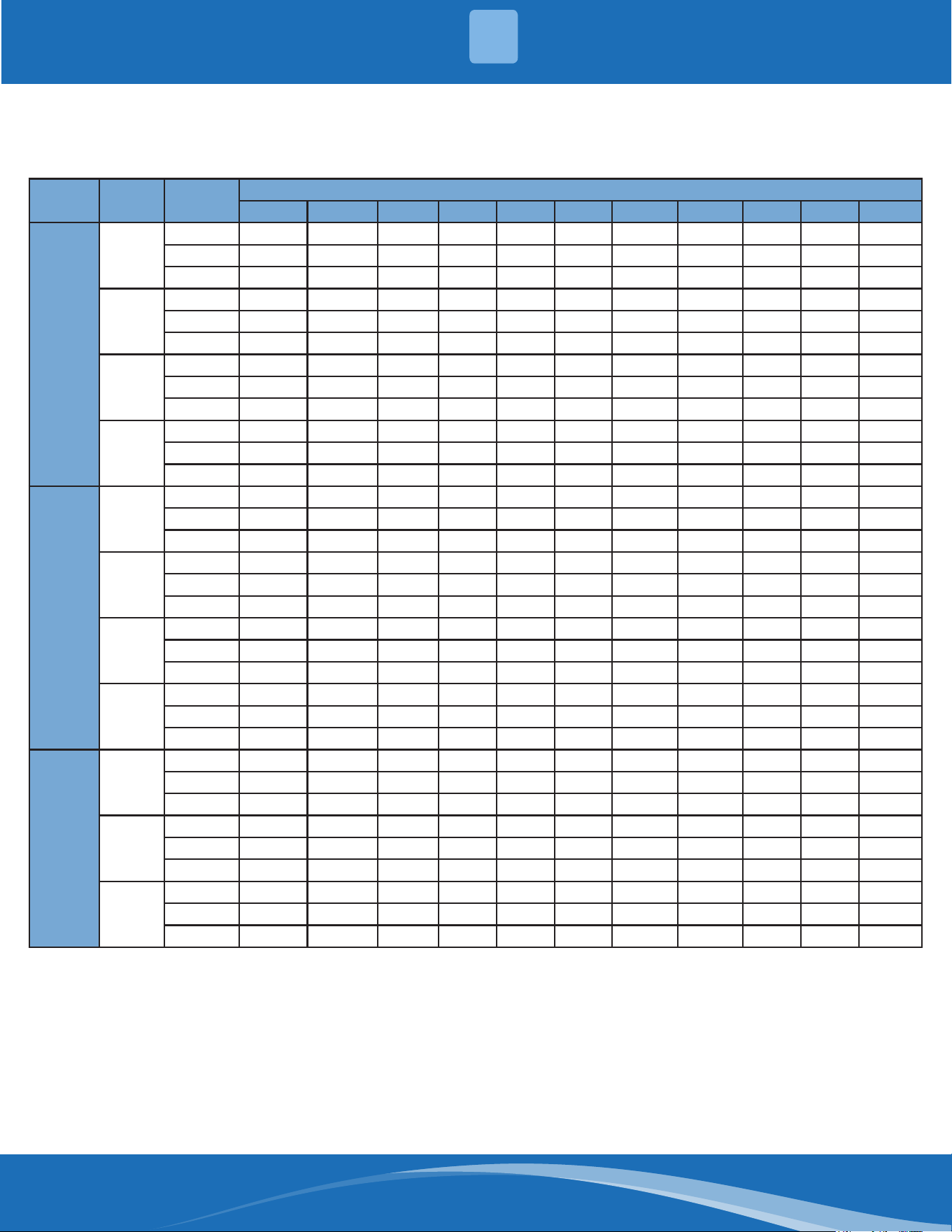
mrcool.com 38
38
Model
Number
Motor
Speed
External Static Pressure-Inches W.C. [kPa]
0[0] 0.1[.02] 0.2[.05] .3[.07] 0.4[.10] 0.5[.12] 0.6[.015] 0.7[.017] 0.8[.20] 0.9[.23] 1.0[.25]
42
Middle-1
(Tap2)
CFM 1153 1102 1056 / / / / / / / /
Current/A 2.09 2.13 2.18 / / / / / / / /
Power/W 227 233 239 / / / / / / / /
Middle-2
(Tap3)
CFM / 1388 1343 1306 1267 1229 1192 1156 1093 1066 1012
Current/A / 3.53 3.55 3.66 3.71 3.77 3.84 3.88 3.92 3.91 3.83
Power/W / 422 418 438 445 453 463 468 473 472 455
Middle-3
(Tap4)
CFM / / / / / / 1387 1354 1309 1231 1168
Current/A / / / / / / 5.09 5.13 2.12 4.90 4.73
Power/W / / / / / / 633 639 638 606 583
High
(Tap5)
CFM / / / / / / / / 1321 1251 1167
Current/A / / / / / / / / 5.19 4.90 4.60
Power/W / / / / / / / / 640 595 586
48
Middle-1
(Tap2)
CFM 1251 / / / / / / / / / /
Current/A 1.67 / / / / / / / / / /
Power/W 192 / / / / / / / / / /
Middle-2
(Tap3)
CFM 1547 1473 1424 1375 1323 1267 1213 / / / /
Current/A 2.8 2.87 2.95 3.04 3.12 3.21 3.3 / / / /
Power/W 340 350 360 371 382 394 407 / / / /
Middle-3
(Tap4)
CFM 1789 1741 1695 1649 1605 1559 1510 1460 1409 1359 1313
Current/A 4.11 4.19 4.28 4.36 4.45 4.54 4.64 4.74 4.83 4.92 5
Power/W 517 528 540 551 564 576 589 603 615 627 639
High
(Tap5)
CFM / / / / / 1755 1696 1630 1563 1490 1438
Current/A / / / / / 5.79 5.76 5.73 5.71 5.68 5.66
Power/W / / / / / 750 745 741 737 733 730
60
Middle-2
(Tap3)
CFM 1547 1473 / / / / / / / / /
Current/A 2.8 2.87 / / / / / / / / /
Power/W 340 350 / / / / / / / / /
Middle-3
(Tap4)
CFM 1789 1741 1695 1649 605 1559 1510 1460 / / /
Current/A 4.11 4.19 4.28 4.36 4.45 4.54 4.64 4.74 / / /
Power/W 517 528 540 551 564 576 589 603 / / /
High
(Tap5)
CFM 2035 1976 1927 1875 1815 1755 1696 1630 1563 1490 1438
Current/A 5.66 5.74 5.81 5.85 5.2 5.79 5.76 5.73 5.71 5.68 5.66
Power/W 733 744 754 758 754 750 745 741 737 733 730
Table 10.1 - Indoor Airow Performance-230 Volts
* The above airow data is for reference only.
AIRFLOW PERFORMANCE
10
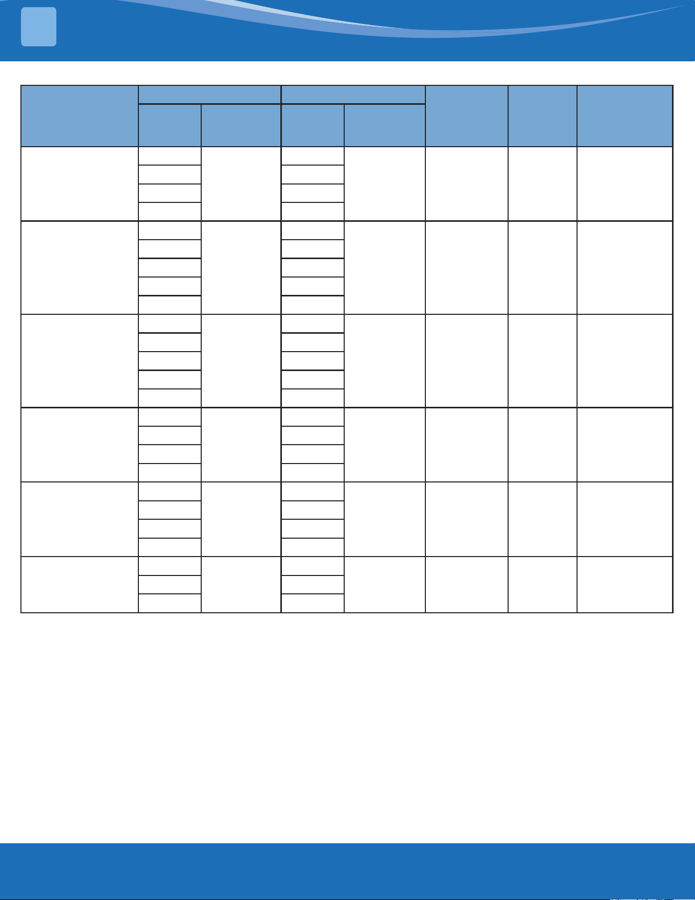
mrcool.com39
Model
Cooling Gas Heat
Blower Size Motor HP
Temperature
Rise Range
(°F)
Usable
Motor
Speed
Motor
Speed from
Factory
Usable
Motor
Speed
Motor
Speed from
Factory
MPG24S060M413B
Low
Middle-1
Low
Middle-1 10x10 1/2 30-60
Middle-1 Middle-1
Middle-2 Middle-2
Middle-3 Middle-3
MPG30S060M413B
Low
Middle-2
Low
Middle-1 10x10 1/2 30-60
Middle-1 Middle-1
Middle-2 Middle-2
Middle-3 Middle-3
High High
MPG36S090M413B
Low
Middle-3
Low
Middle-1 10x10 1/2 40-70
Middle-1 Middle-1
Middle-2 Middle-2
Middle-3 Middle-3
High High
MPG42S090M413B
Middle-1
Middle-2
Middle-1
Middle-3 10x10 3/4 35-65
Middle-2 Middle-2
Middle-3 Middle-3
High High
MPG48S090M413B
Middle-1
Middle-3
Middle-1
Middle-2 11x10-5/8 3/4 30-60
Middle-2 Middle-2
Middle-3 Middle-3
High High
MPG60S110M413B
Middle-2
High
Middle-2
Middle-3 11x10-5/8 3/4 30-60Middle-3 Middle-3
High High
• The air distribution system has the greatest eect on airow. The duct system is totally controlled by the
contractor. For this reason, the contractor should use only industry-recognized procedures.
• Each ton of cooling requires between 350 and 450 cubic feet of air per minute (CFM), or 400 CFM nominally.
• Duct design and construction should be carefully done. System performance can be lowered dramatically
through bad planning or workmanship.
• Air supply diusers must be selected and located carefully. They must be sized and positioned to deliver
treated air along the perimeter of the space. If they are too small for their intended airow, they become noisy.
If they are not located properly, they cause drafts. Return air grilles must be properly sized to carry air back to
the blower. If they are too small, they also cause noise.
• The installers should balance the air distribution system to ensure proper quiet airow to all rooms in the
home. This ensures a comfortable living space.
• An air velocity meter or airow hood can give a reading of system CFM.
• When installation, installer should select the air speed according to the actual setting static pressure. Please
refer to the Table 10.1 & Table 10.2.
Table 10.2 - Motor Speed from Factory
AIRFLOW PERFORMANCE
10
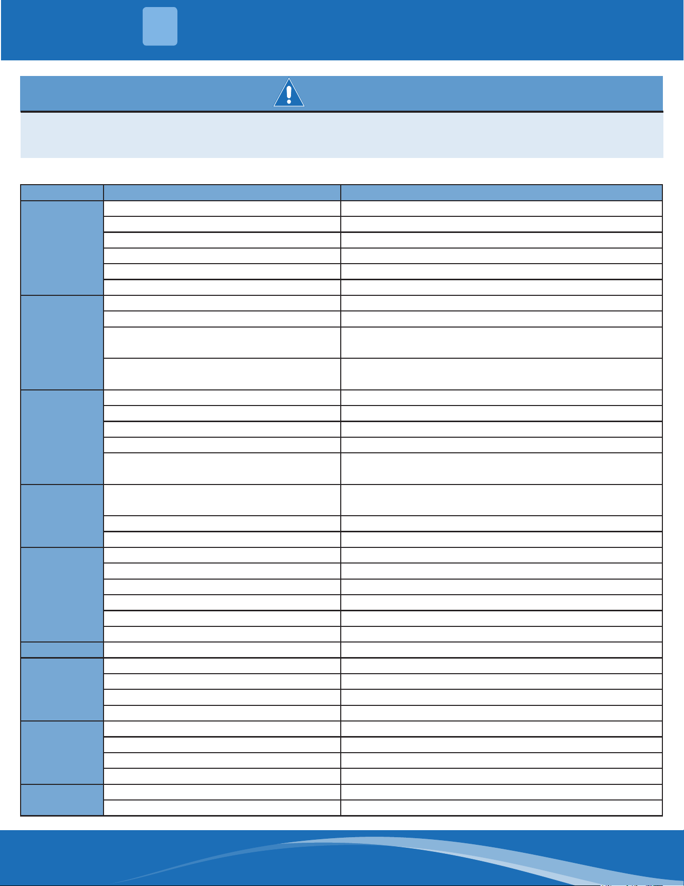
mrcool.com 40
40
WARNING
Components trouble shooting requires opening control box with power on. Use extreme care while
working on this condition.
Check nameplate and this instruction when making wire connections.
Table 11.1 - Troubleshooting Chart
Symptom Possible Cause Remedy
Unit will not run
Power o or loose electrical connection Check for correct voltage at compressor contactor in control box.
Thermostat out of calibration; set too high Reset
Failed Contactor Check for 24 volts at contactor coil; replace if contacts are open
Blown fuses Replace fuses
Transformer defective Check wiring; replace transformer
Interconnecting low voltage wiring damaged Replace thermostat wiring
Condenser
fan runs but
compressor
doesn't
Run or start capacitor failed (single phase only) Replace
Loose connection Check for correct voltage at compressor; check and tighten all connections
Compressor stuck, grounded, or motor winding open
internal overload
Wait at least 2 hours for overload to reset. If still open, replace the
compressor.
Low voltage condition
Determine cause and correct. At compressor terminals, voltages must be
within 10% of rating plate volts when unit is operating.
Insucient
Cooling
Improperly sized unit Recalculate load
Improper airow Check; should be approximately 400 CFM per ton.
Incorrect refrigerant charge Charge per procedure attached to unit service panel
Air, non-condensible or moisture in system Recover refrigerant, evacuate & recharge, add lter drier
Incorrect voltage
Determine cause and correct. At compressor terminals, voltages must be
within 10% of rating plate volts when unit is operating.
Compressor
Short Cycles
Incorrect voltage
At compressor terminals, voltage must be ±10% or nameplate marking
when unit is operating.
Defective overload protector Replace; Check for correct voltage
Refrigerant undercharge Add refrigerant
Compressor
Operates
Continuously
Dirty air lter Replace lter
Unit undersized for load Decrease load or increase unit size
Thermostat temperature set too low Reset thermostat
Low refrigerant charge Locate leak, repair, and recharge
Air in system Recover refrigerant, evacuate system, and recharge
Outdoor coil dirty or restricted Clean coil or remove restriction
Registers sweat Low evaporator airow Increase speed of blower to reduce restriction; replace air lter
High head-low
vapor pressure
Restriction in liquid line, expansion device or lter drier Remove or replace defective component
Flow check piston size too small Change to correct sized piston
Incorrect capillary tubes Change coil assembly
TXV does not open Replace TXV
High head-
high or normal
vapor pressure
(Cooling Mode)
Dirty condenser coil Clean coil
Refrigerant overcharge Correct system charge
Condenser fan not running Repair or replace
Air or non-condensible in system Recover refrigerant, evacuate, and recharge
Low head-high
vapor pressures
Defective compressor valves Replace compressor
Incorrect capillary tubes Replace coil assembly
TROUBLESHOOTING & WIRING DIAGRAMS
11
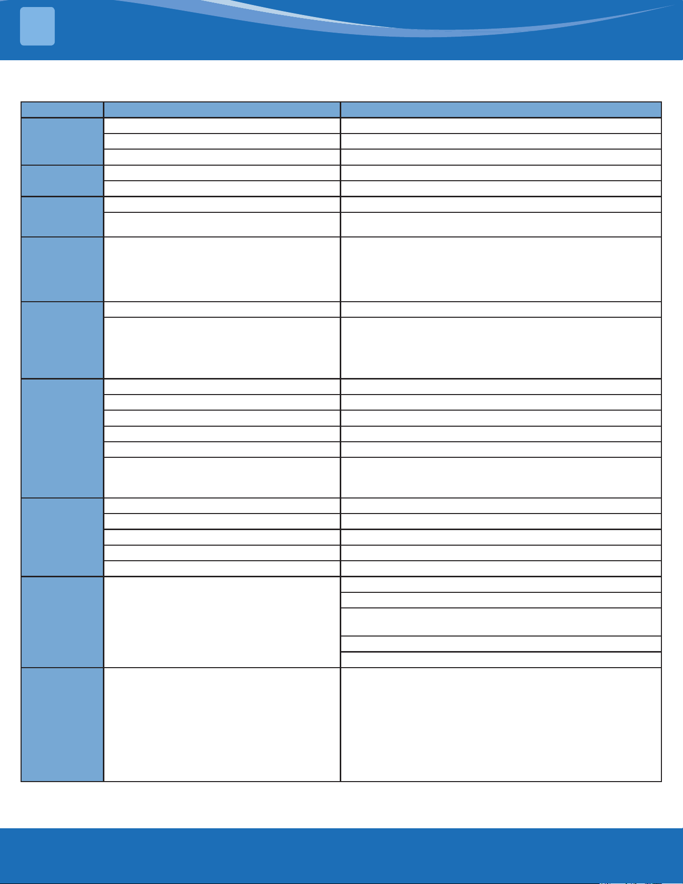
mrcool.com41
Symptom Possible Cause Remedy
Low vapor-cool
compressor-iced
evaporator coil
Low evaporator airow Increase speed of blower or reduce restriction; replace air lter
Operating below 65°F outdoors Add Low Ambient Kit
Moisture in system Recover refrigerant; evacuate and recharge; add lter drier
High Vapor
Pressure
Excessive load Recheck load calculation
Defective compressor Replace
Fluctuating
Head & Vapor
Pressure
TXV Hunting Check TXV bulb clamp; check air distribution on coil; replace TXV
Air or non-condensible in system Recover refrigerant; evacuate and recharge
Gurgle or
pulsing noise
at expansion
device or liquid
line
Air or non-condensible in system Recover refrigerant; evacuate and recharge
Circulating
air blower &
inducer run
continuously,
compressor will
not start
Manual reset over-temperature control tipped Reset or replace
Wire loose in limit circuit Check wiring
Burners will not
ignite
Water in gas line Drain. Install drip leg.
No power to furnace Check power supply fuses, wiring, or circuit breaker.
No 24 volts power supply to control circuit Check transformer.
Mis-wired or loose connections Check all wiring and wire nut connections
Misaligned spark electrodes Check ame ignition and sense electrode positioning. Adjust as necessary.
No gas at main burners
Check gas line for air. Purge as necessary. NOTE: After purging gas line of
air, wait at least 5 minutes for any gas to dissipate before attempting to
light unit. Check gas valve.
Inadequate
heating
Dirty air lter Clean or replace lter as necessary
Gas input to furnace too low Check gas pressure at manifold with that on unit nameplate.
Unit undersized for application Replace with proper unit or add additional unit.
Restricted airow Clean or replace lter; remove any restriction
Limit switch cycles main burners Check rotation of blower, temperature rise of unit. Adjust as necessary.
Poor ame
characteristics
Incomplete combustion results in: Aldehyde odors, carbon
monoxide, sooting ame, oating ame
Tighten all screws around burner compartment
Cracked heat exchanger. Replace as necessary.
Unit over-red. Reduce input (change orices or adjust gas line or manifold
pressure).
Check burner alignment
Inspect heat exchanger for blockage. Clean as necessary.
Both condenser
fan and
compressor
startup and
shutdown
frequently
(about three
minutes per
cycle)
Abnormal high discharge pressure caused the high
pressure switch act
Refer to the remedy of "High head-high or normal vapor pressure-cooling
mode".
Table 11.1 - Troubleshooting Chart (Continued)
TROUBLESHOOTING & WIRING DIAGRAMS
11
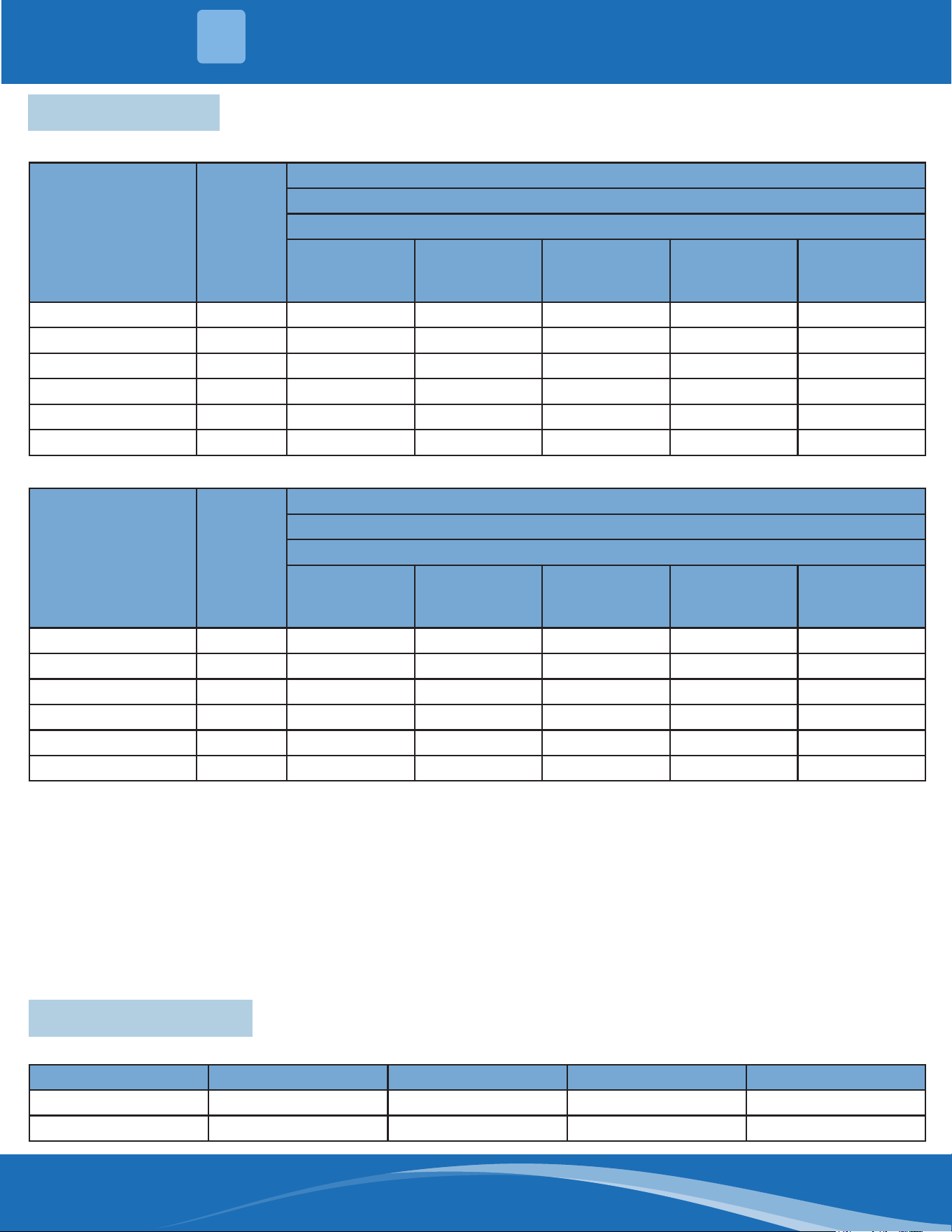
mrcool.com 42
42
Model
Number
of
Burners
Natural Gas
Heating Valve 1075 Btu/Cu.Ft.
Specic Gravity 0.65/Manifold Pressure @ 3.5" W.C.
Elevation
0-2000' (USA/
Canada)
Elevation
4000' (USA
Only)
Elevation
6000' (USA
Only)
Elevation
8000' (USA
Only)
Elevation
2000-4500'
(Canada)
MPG24S060M413B 5 51 53 53 54 51
MPG30S060M413B 5 51 53 53 54 51
MPG36S090M413B 7 51 52 53 53 51
MPG42S090M413B 7 51 52 53 53 51
MPG48S090M413B 6 49 50 51 52 49
MPG60S110M413B 7 49 50 51 51 49
Model
Number
of
Burners
Natural Gas
Heating Valve 2500 Btu/Cu.Ft.
Specic Gravity 0.65/Manifold Pressure @ 10" W.C.
Elevation
0-2000' (USA/
Canada)
Elevation
4000' (USA
Only)
Elevation
6000' (USA
Only)
Elevation
8000' (USA
Only)
Elevation
2000-4500'
(Canada)
MPG24S060M413B 5 59 63 64 64 59
MPG30S060M413B 5 59 63 64 64 59
MPG36S090M413B 7 59 62 63 64 59
MPG42S090M413B 7 59 62 63 64 59
MPG48S090M413B 6 56 59 60 61 56
MPG60S110M413B 7 56 58 59 60 56
For addressing derating at altitudes above 2000 ft. (610 m), the instructions shall indicate one of the following:
1. Installation of this furnace at altitudes above 2000 ft (610 m) shall be in accordance with local codes, or in the
absence of local codes, the National Fuel Gas Code, ANSI Z223.1/NFPA 54 or National Standard of Canada,
Natural Gas and Propane Installation Code, CSA B149.1.
2. For furnaces requiring modications other than only gas orice and/or manifold pressure adjustment for
installation at high altitude, “Installation of this furnace at altitudes above 2000 ft (610 m) shall be made in
accordance with the Listed High Altitude Conversion Kit available with this furnace.”
3. For furnaces requiring only gas orice and/or manifold pressure adjustment for installation at high altitude, the
furnace installation instructions shall provide adequate details on proper adjustments for various altitudes.
Model Type Rated Voltage Rated Current Dimensions
50T / 250Vac 3.15A 5.2x20mm
522 Time Delay 250Vac 3.15A 5x20mm
11.2 High Altitude
11.3 Fuse Parameters
TROUBLESHOOTING & WIRING DIAGRAMS
11
Table 11.2a- 1075 Btu/Cu. Ft; 3.5" W.C.
Table 11.2b- 2500 Btu/Cu. Ft; 10" W.C.
Table 11.3- Fuse Specications
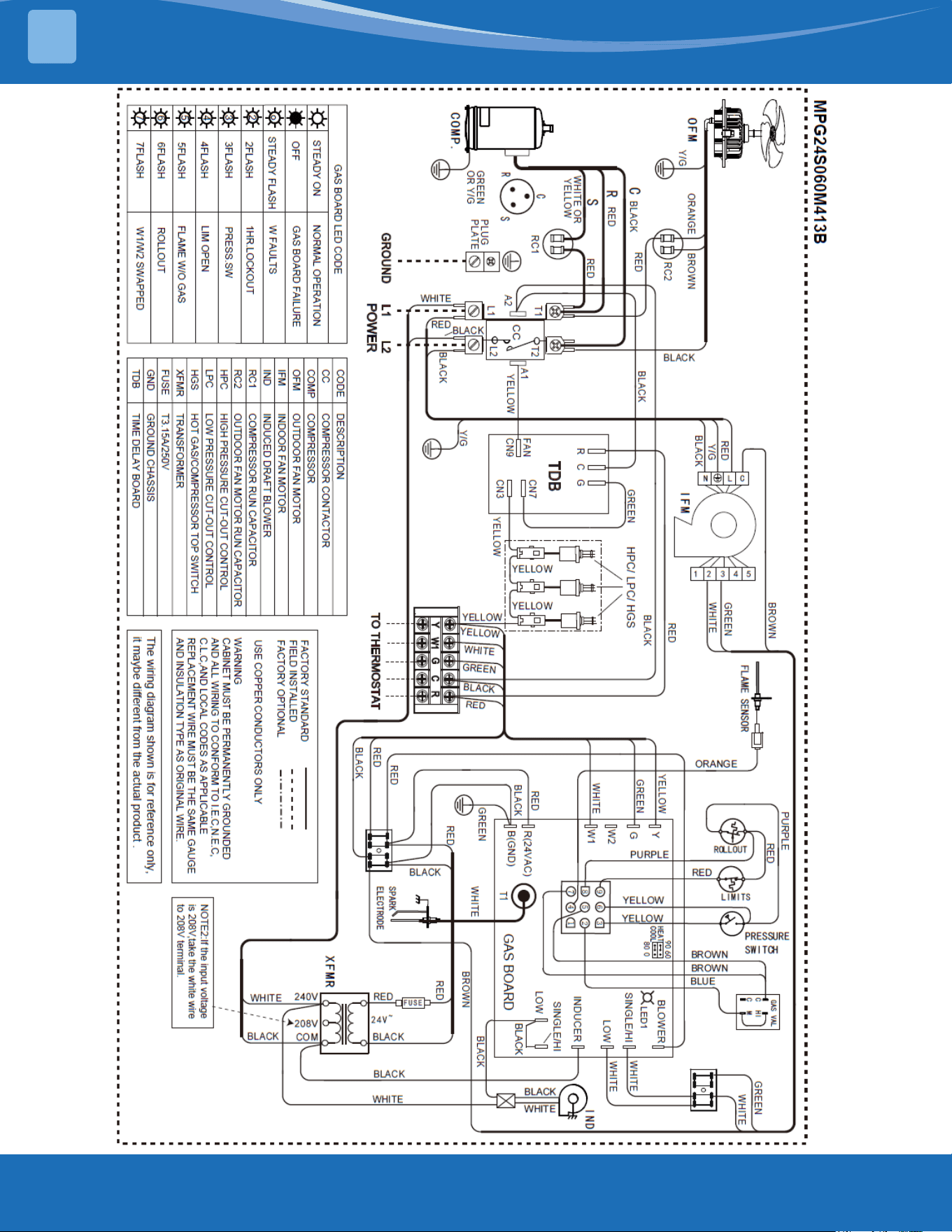
mrcool.com43
TROUBLESHOOTING & WIRING DIAGRAMS
11
Figure 11a-
MPG24
Wiring
Diagram
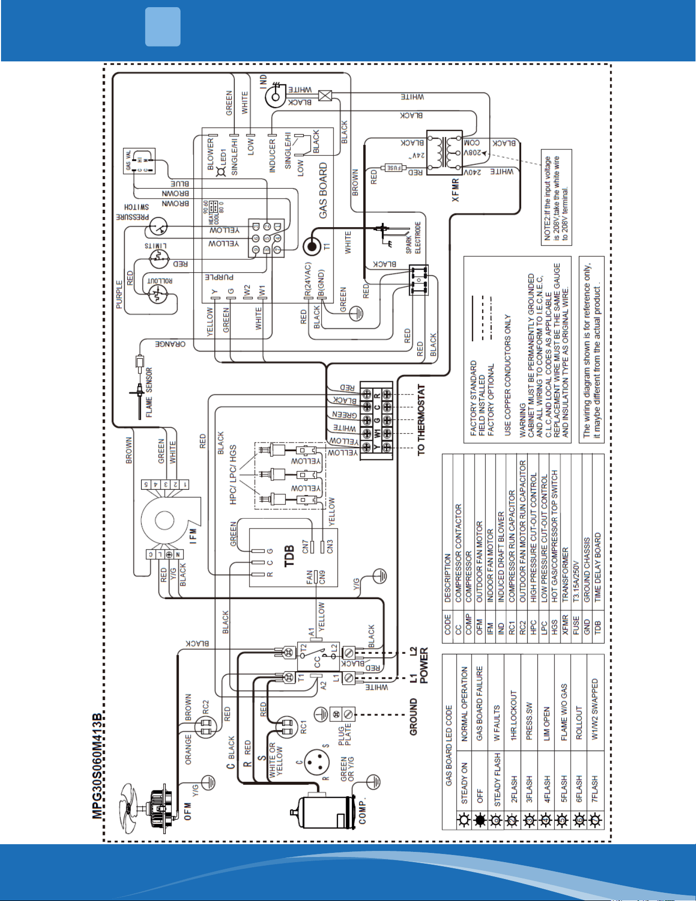
mrcool.com 44
44
TROUBLESHOOTING & WIRING DIAGRAMS
11
Figure 11b-
MPG30
Wiring
Diagram
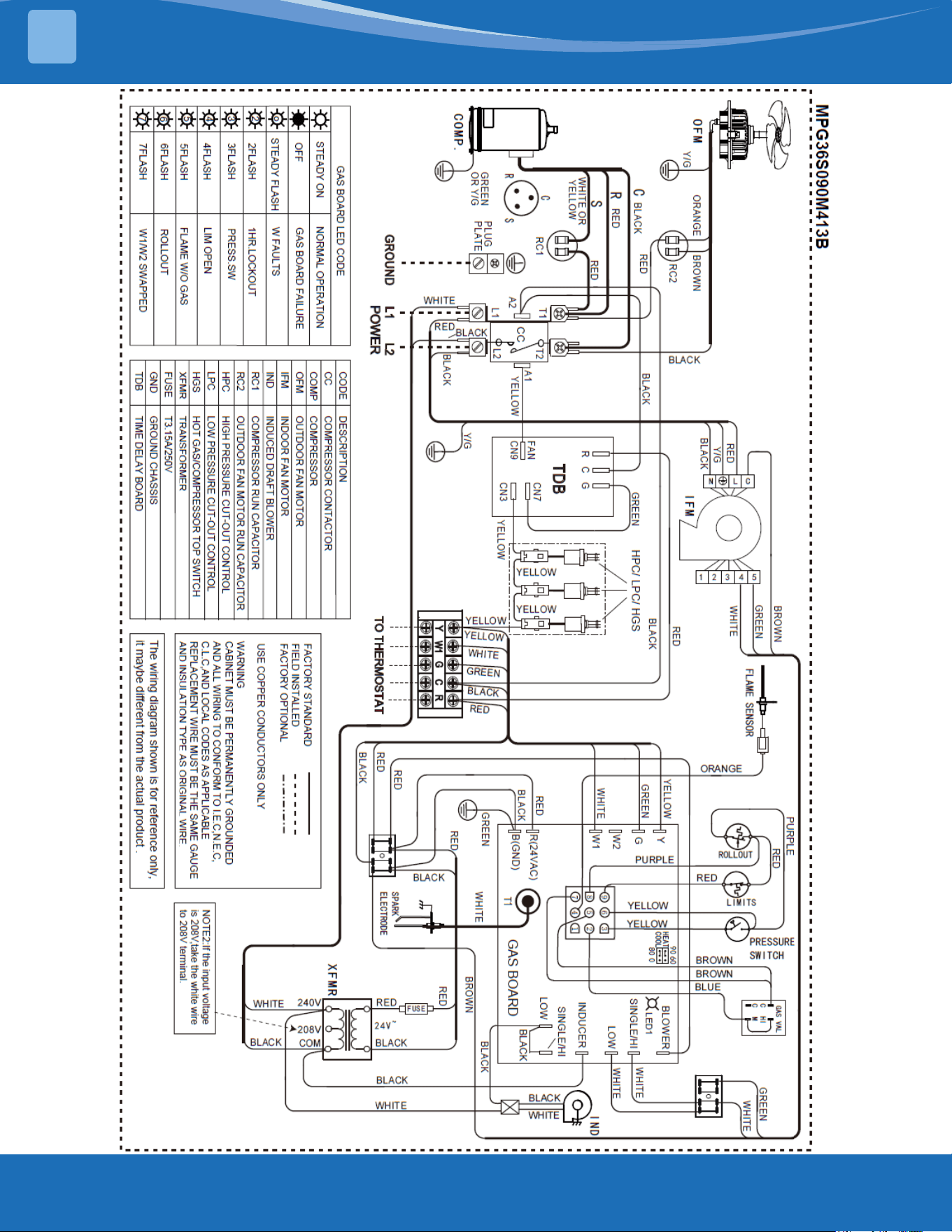
mrcool.com45
TROUBLESHOOTING & WIRING DIAGRAMS
11
Figure 11c-
MPG36
Wiring
Diagram

mrcool.com 46
46
TROUBLESHOOTING & WIRING DIAGRAMS
11
Figure 11b-
MPG342
Wiring
Diagram
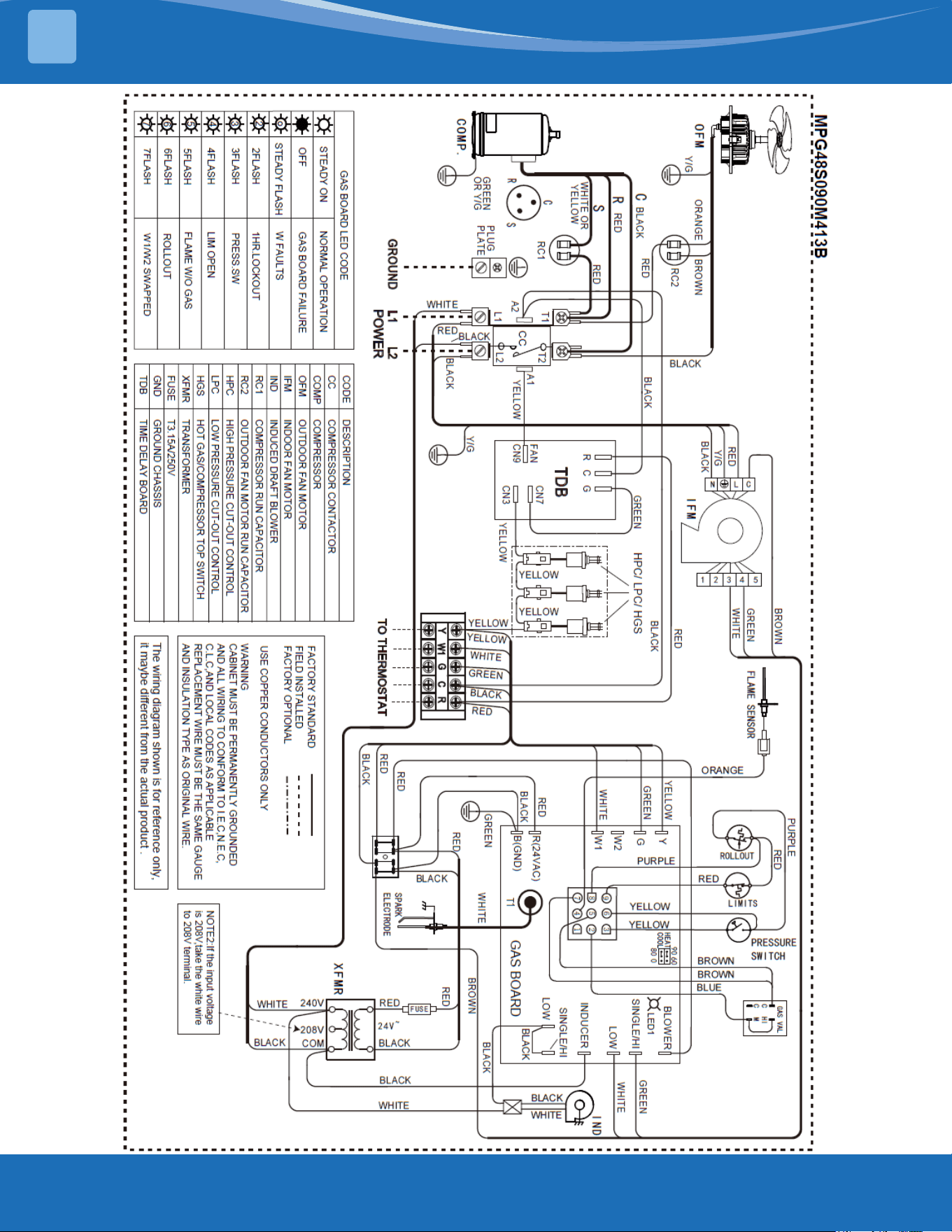
mrcool.com47
TROUBLESHOOTING & WIRING DIAGRAMS
11
Figure 11b-
MPG48
Wiring
Diagram
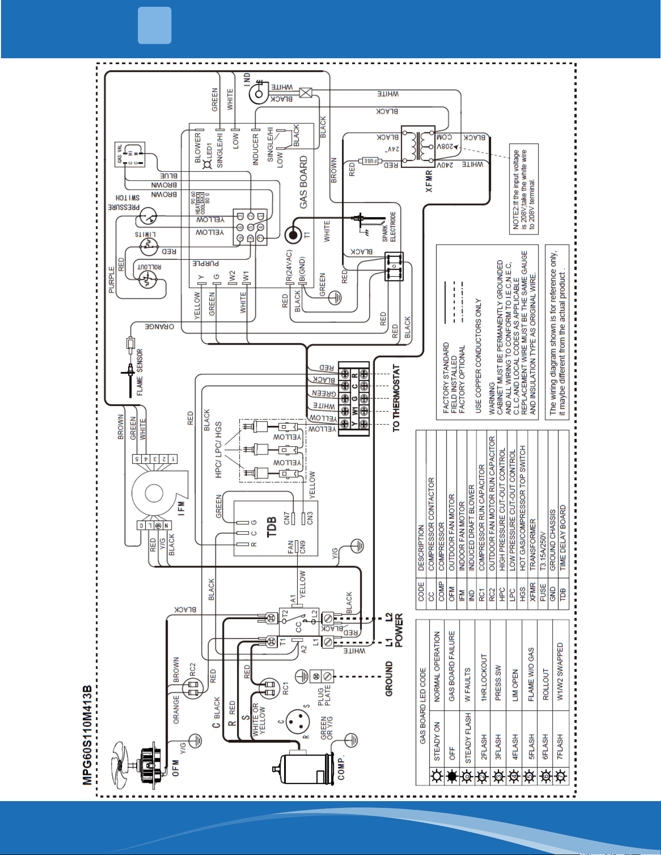
mrcool.com 48
48
TROUBLESHOOTING & WIRING DIAGRAMS
11
Figure 11b-
MPG60
Wiring
Diagram

VersaPro™
Gas Package Unit
Installation Manual
The design and specications of this product and/or manual are subject to change without prior notice.
Consult with the sales agency or manufacturer for details.