The Signature Series is NOT designed for amateur installation. Installation SHOULD be performed by an authorized technician.
Please read this manual carefully before installation and keep it for future reference.
The Signature Series is NOT designed for amateur installation. Installation SHOULD be performed by an authorized technician.
Please read this manual carefully before installation and keep it for future reference.
Owner & Installation
Manual
MGM80*SE-XA Warm Air Gas Furnace
Signature Series
507330-02C mrcool.com Page 1 of 35
INSTALLATION INSTRUCTIONS
MGM80*SE*XA
Warm Air Gas Furnace
Save these instructions for future reference
(P) 507330-02C
*P507330-02C*
This manual must be left with the homeowner for future reference.
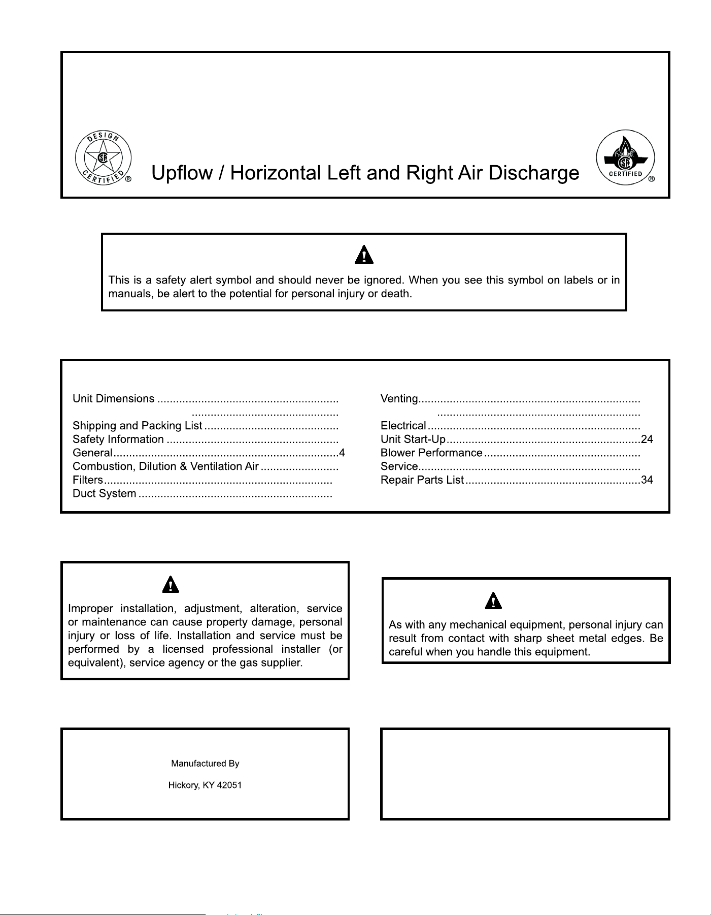
WARNING
CAUTION
Table of Contents
2
MGM80*EGas Furnace 3
3
3
5
10
10
11
Gas Piping 18
20
29
33
MRCOOL, LLC
507330-02CPage 2 of 35 mrcool.com
Top
View
Right Side
View
Bottom
View
Front View
C
23-1/2
(597)
25 (635)
D
3-1/4
(83)
23
(584)
14
(356)
15-1/2
(394)
23-7/8
(606)
30
(762)
26
(660)
19-1/2 (495)
28-3/8 (721)
B
33
(838)
A
1
NOTE -C*20 5
2
3
*
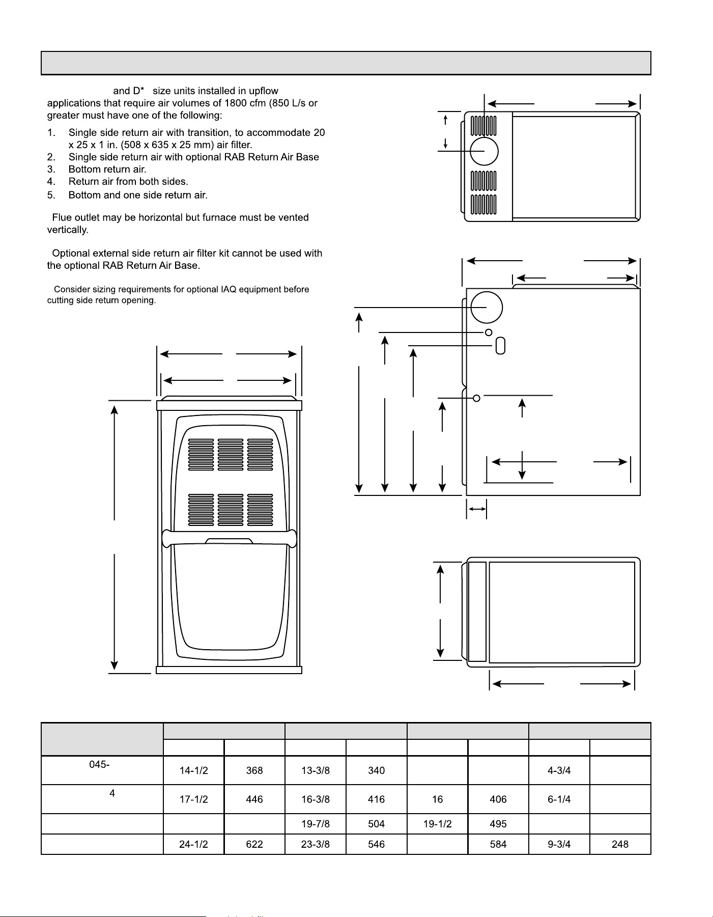
Unit Dimensions
Capacity
A B C D
in. mm in. mm in. mm in. mm
3
070-3
13 330 121
090-
090-5
159
110-5 21 533
8 203
135-5 23
507330-02C mrcool.com Page 3 of 35
MGM80*SE*XA Gas Furnace
MGM80*E
Shipping and Packing List
Safety Information
DANGER OF EXPLOSION!
DANGER
Clearances
Installed Locations
Temperature Rise
NOTE: Furnace must be adjusted to obtain a temperature
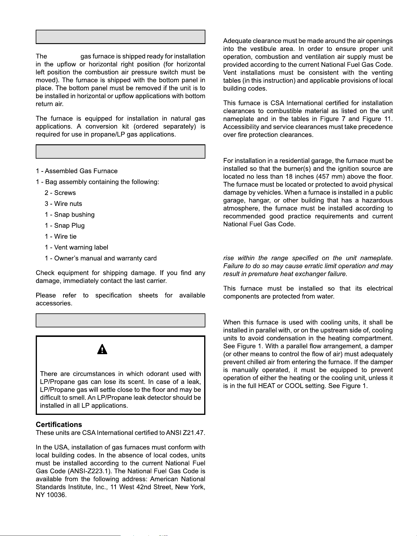
Installed in Combination with a Cooling Coil
507330-02Cmrcool.com
Figure 1.
Heating Unit Installed Parallel to Air Handler Unit
Heating Unit Installed Upstream of Cooling Unit
NOTE:
Use of Furnace as a Construction Heater
DO NOT USE THE UNIT FOR CONSTRUCTION HEAT
UNLESS ALL OF THE FOLLOWING CRITERIA ARE
MET:
COMPONENT FAILURE AS A RESULT OF FAILURE TO
General
507330-02C mrcool.com Page 5 of 35
•
•
•
•
NOTE:
•
•
•
Combustion, Dilution & Ventilation Air
•
•
•
•
•
•
•
•
•
•
•
•
WARNING
507330-02Cmrcool.com
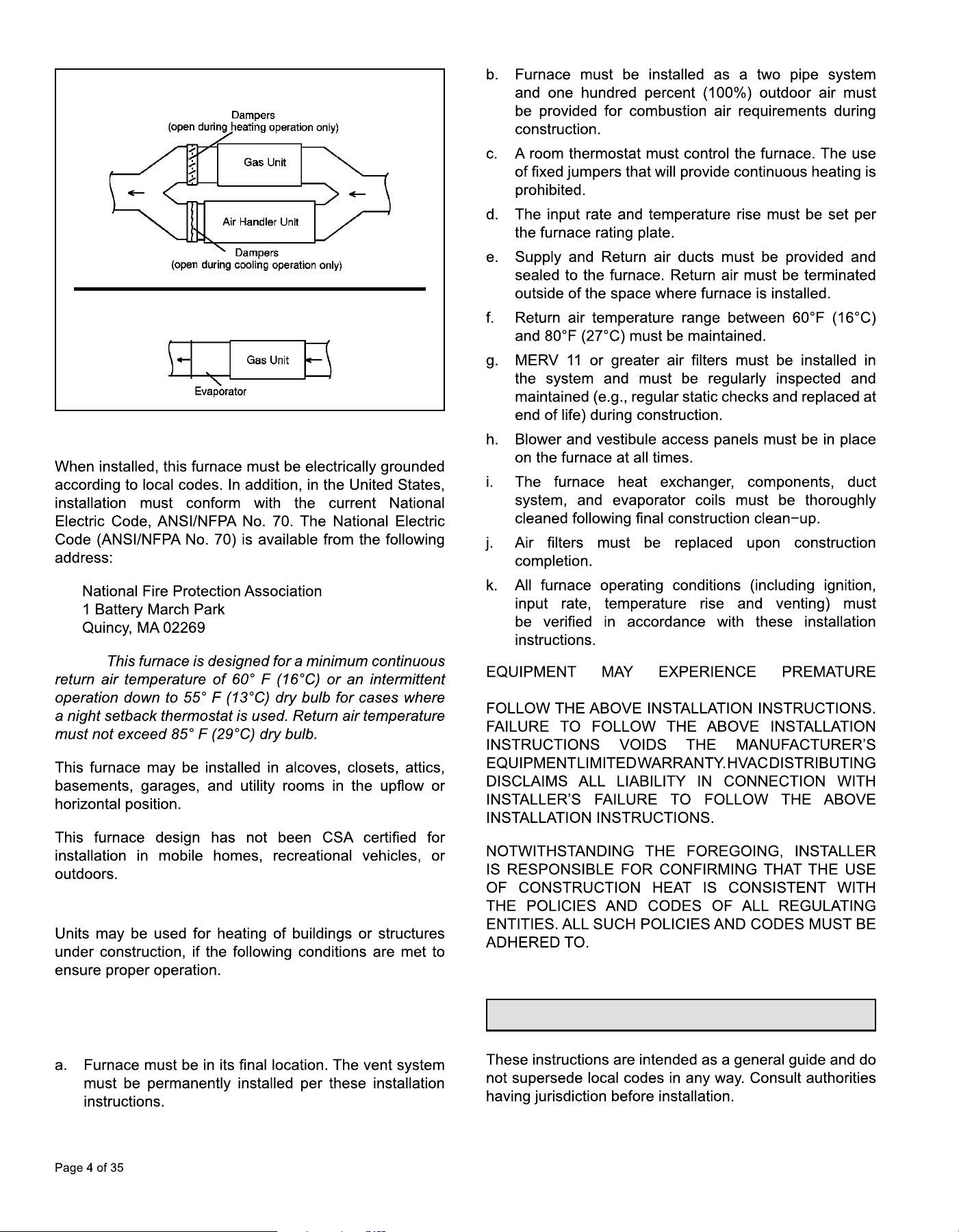
Figure 2.
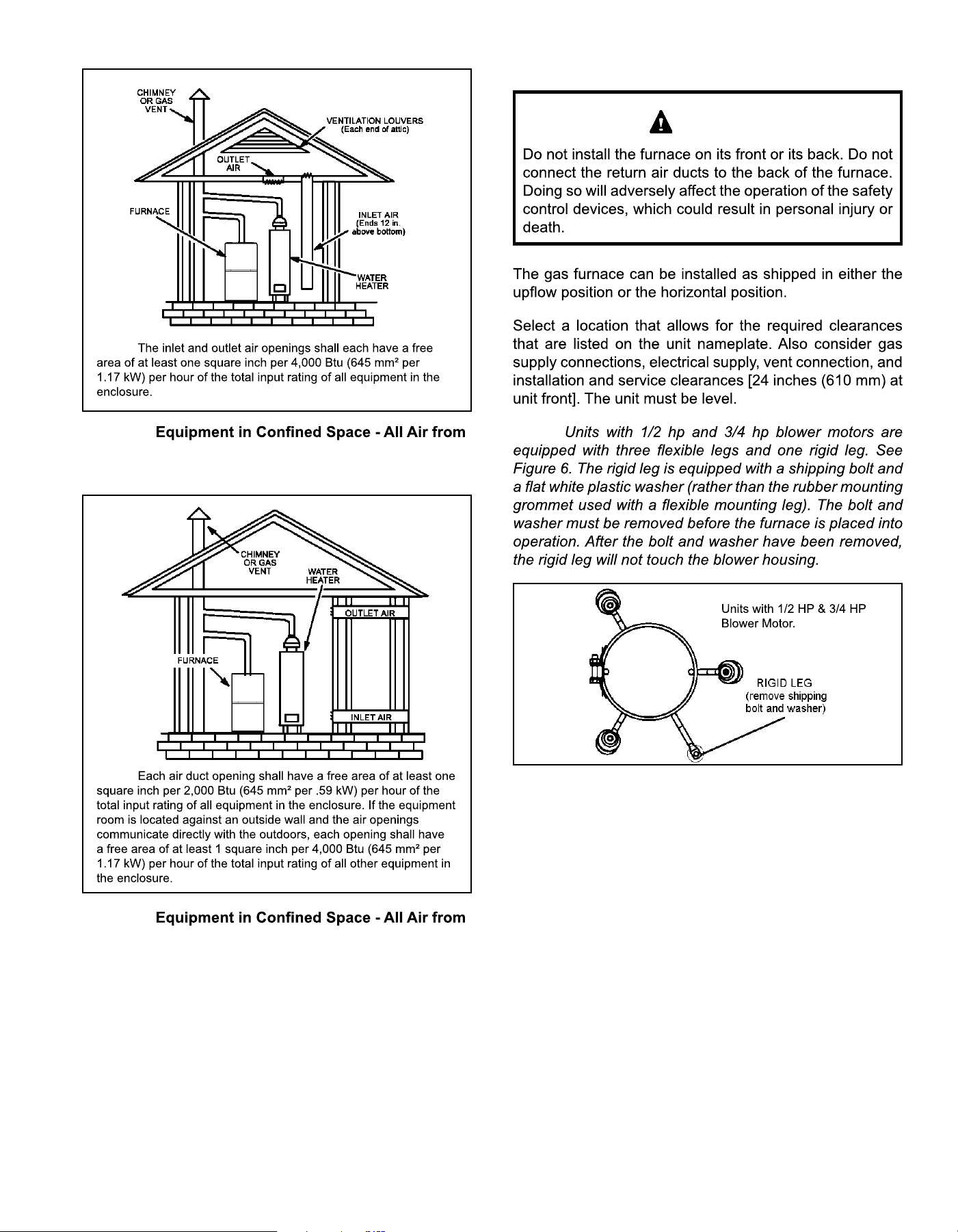
Inside
NOTE:
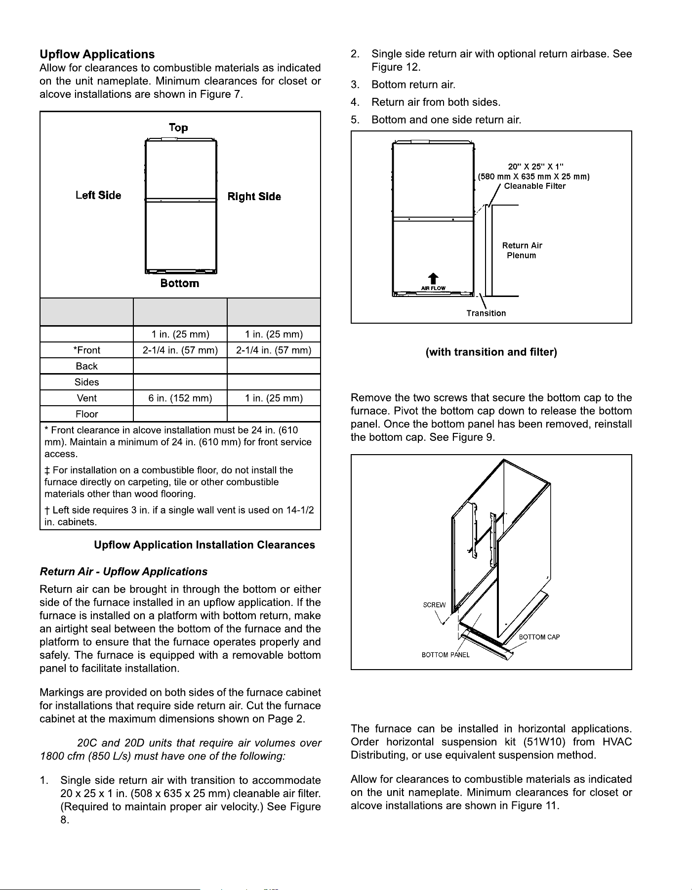
Air from Inside
Air from Outside
Figure 3.
Outside
(Inlet Air from Crawl Space & Outlet Air to Ventilated
Attic)
NOTE:
507330-02C mrcool.com Page 7 of 35
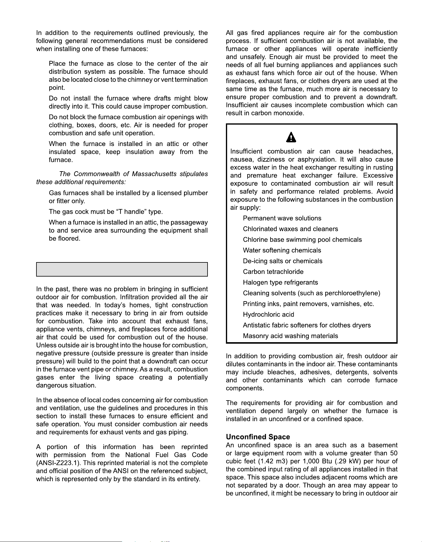
Figure 4.
Outside
(All Air through Ventilated Attic)
NOTE:
Figure 5.
Outside
NOTE:
Setting Equipment
WARNING
NOTE:
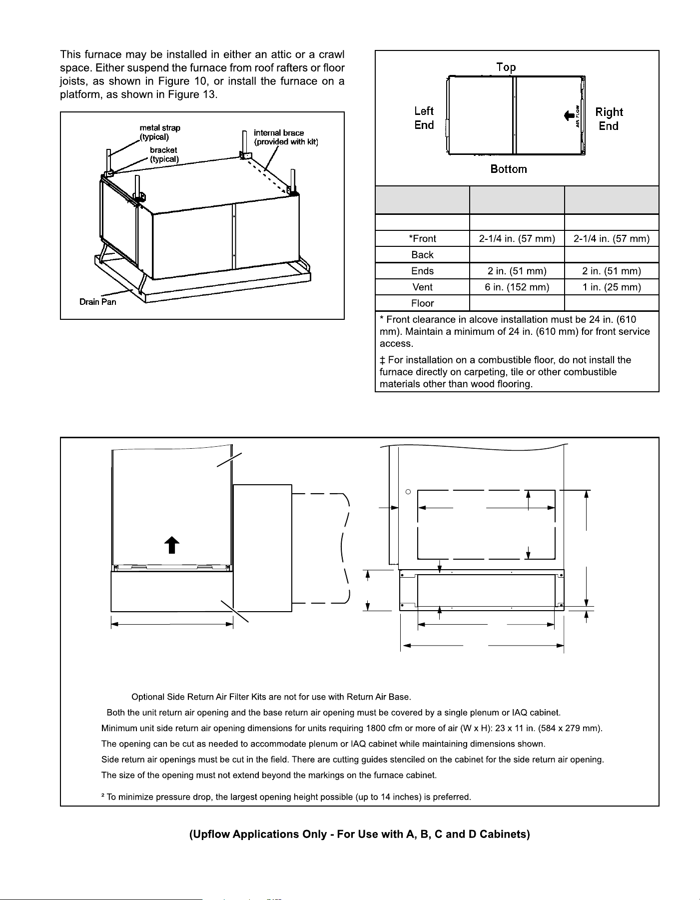
Figure 6.
507330-02CPage 8 of 35 mrcool.com
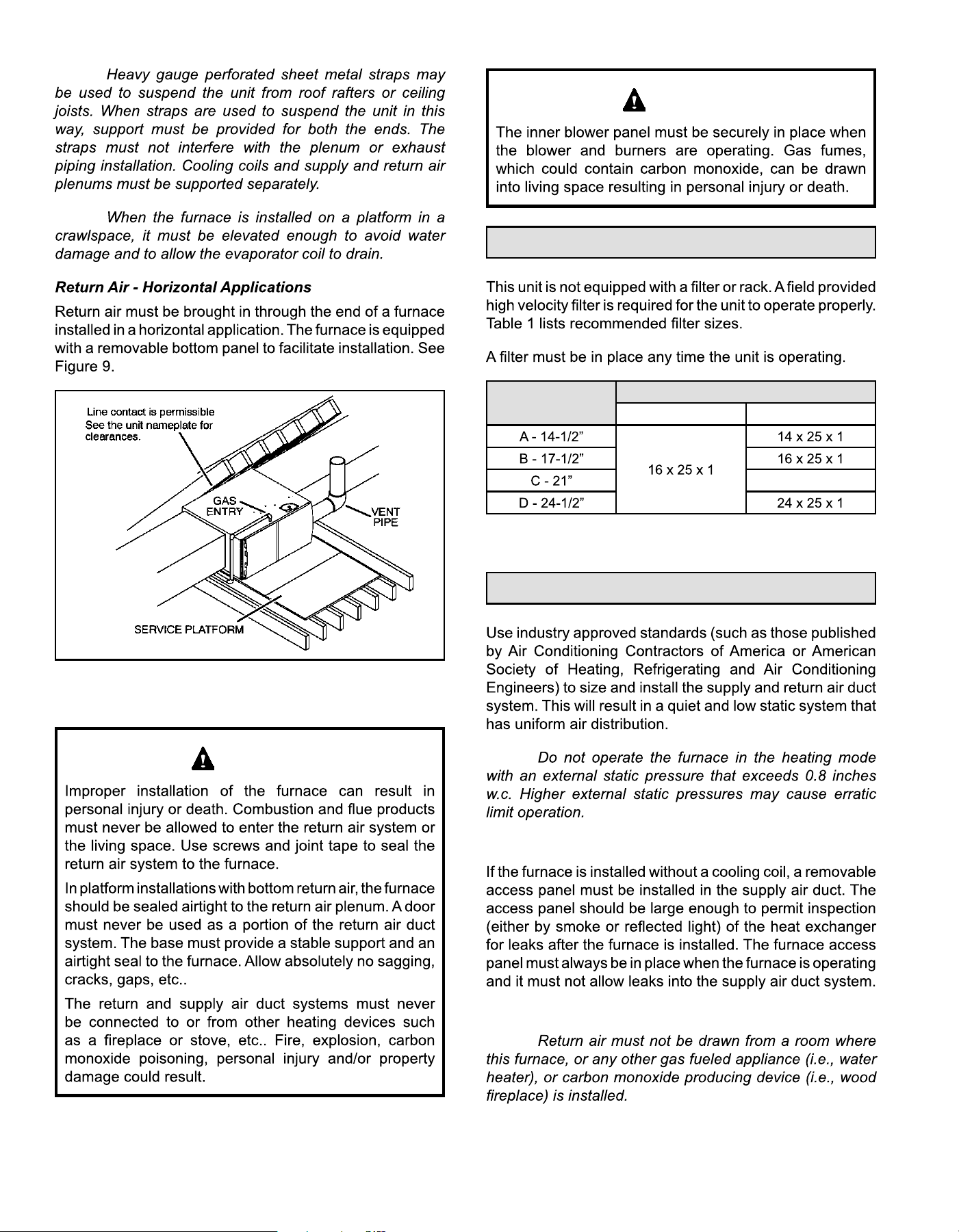
Figure 7.
Type of Vent
Connector
Type C Type B
1
Top
0 0
0† 0
0‡ 0‡
NOTE:
Figure 8. Single Side Return Air
Removing the Bottom Panel
Figure 9. Removing the Bottom Panel
Horizontal Applications
507330-02C mrcool.com Page 9 of 35
Figure 10. Typical Horizontal Application
Unit Suspended in Attic or Crawl Space
Figure 11. Horizontal Application Installation
Clearances
Type of Vent
Connector
Type C Type B
1
Top 0 0
0 0
0‡ 0‡
Figure 12. Optional Return Air Base
FRONT VIEW
1
Unit side return air
Opening
SIDE VIEW
3−1/4
(83)
1
23 (584)
Overall
(Maximum)
(584)
23
3/4
(19)
1
22−7/16
(570)
Overall
(Maximum)
SIDE RETURN
AIR OPENINGS
(Either Side)
5−5/8
(143)
1
Minimum
11 (279)
2
Maximum
14 (356)
(683)
26−7/8
7−1/4
(184)
FURNACE
FRONT
AIR FLOW
IF BASE
IS USED
WITHOUT
IAQ CABINET,
A SINGLE
RETURN AIR
PLENUM
MUST
COVER BOTH
UNIT AND
RETURN
AIR BASE
OPENINGS
INDOOR AIR
QUALITY
CABINET
AIR BASE
OPTIONAL
RETURN
17-1/2 (446) B Width (68W62)
21 (533) C Width (68W63)
24-1/2 (622) D Width (68W64)
14-1/2 (368) A Width (65W75)
NOTE:
1
507330-02CPage 10 of 35 mrcool.com
NOTE:
NOTE:
Figure 13. Horizontal Application
Unit Installed on Platform
WARNING
WARNING
Filters
Furnace Cabinet
Width
Filter Size
Side Return Bottom Return
20 x 25 x 1
Table 1.
Duct System
NOTE:
Supply Air Plenum
Return Air Plenum
NOTE:
507330-02C mrcool.com Page 11 of 35
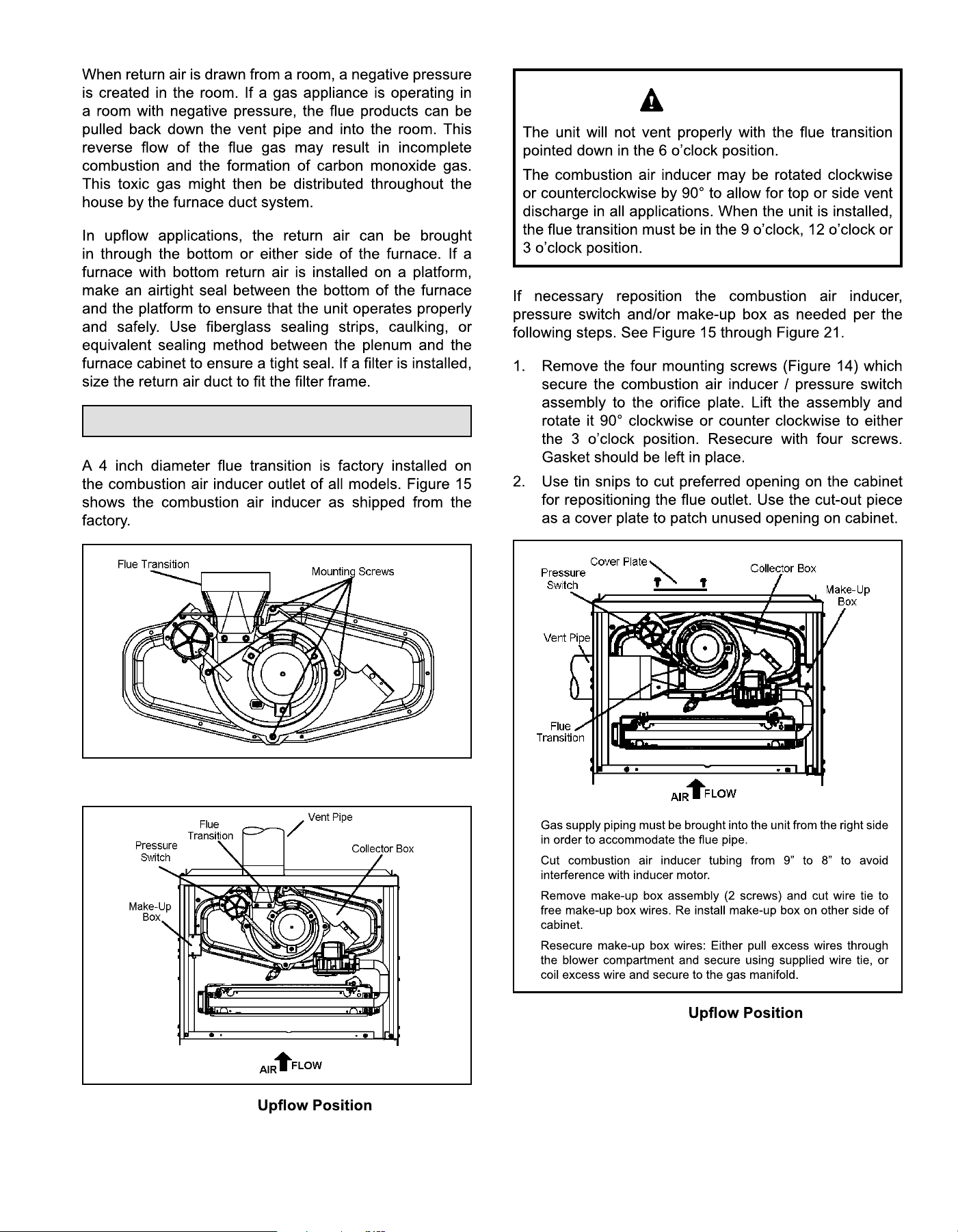
Venting
Figure 14. Mounting Screws Location
Figure 15.
Top Vent Discharge
IMPORTANT
•
•
•
•
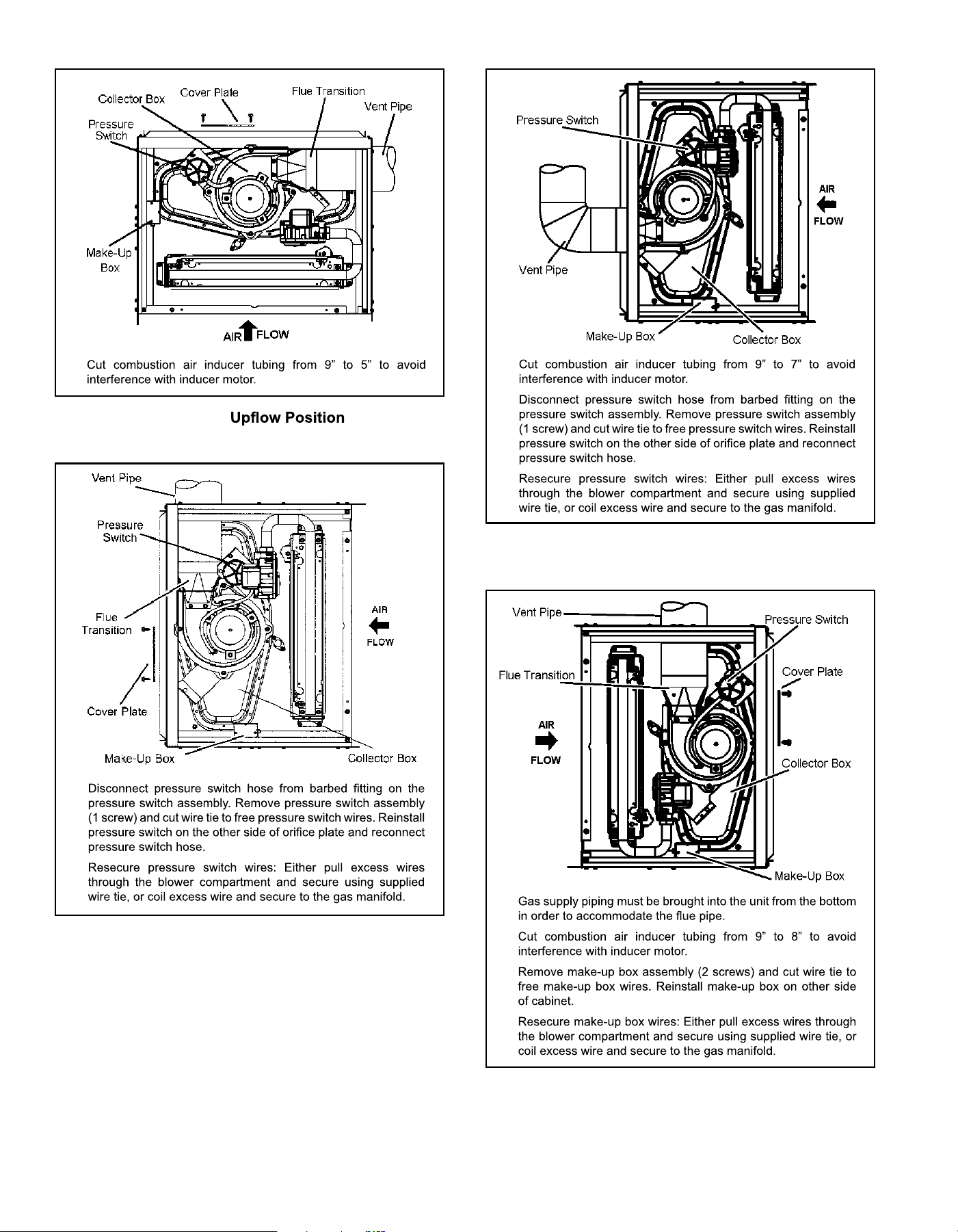
Figure 16.
Left Side Vent Discharge
507330-02CPage 12 of 35 mrcool.com
Figure 17.
Right Side Vent Discharge
•
Figure 18. Horizontal Left Position
Top Vent Discharge
•
•
Figure 19. Horizontal Left Position
Side Vent Discharge
•
•
•
Figure 20. Horizontal Right Position
Top Vent Discharge
•
•
•
•
507330-02C mrcool.com Page 13 of 35
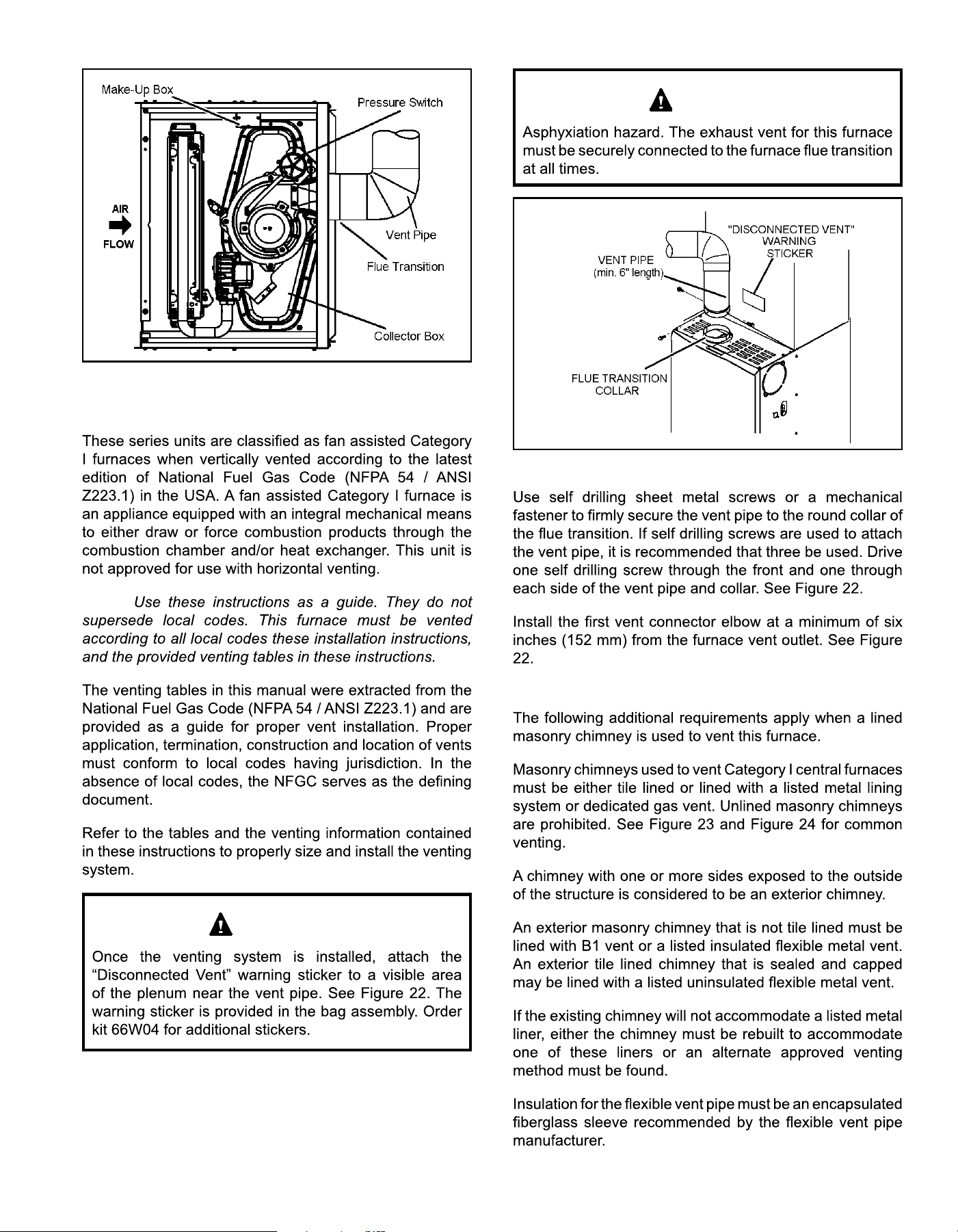
Figure 21. Horizontal Right Position
Side Vent Discharge
NOTE:
IMPORTANT
WARNING
Figure 22. Vent Connection
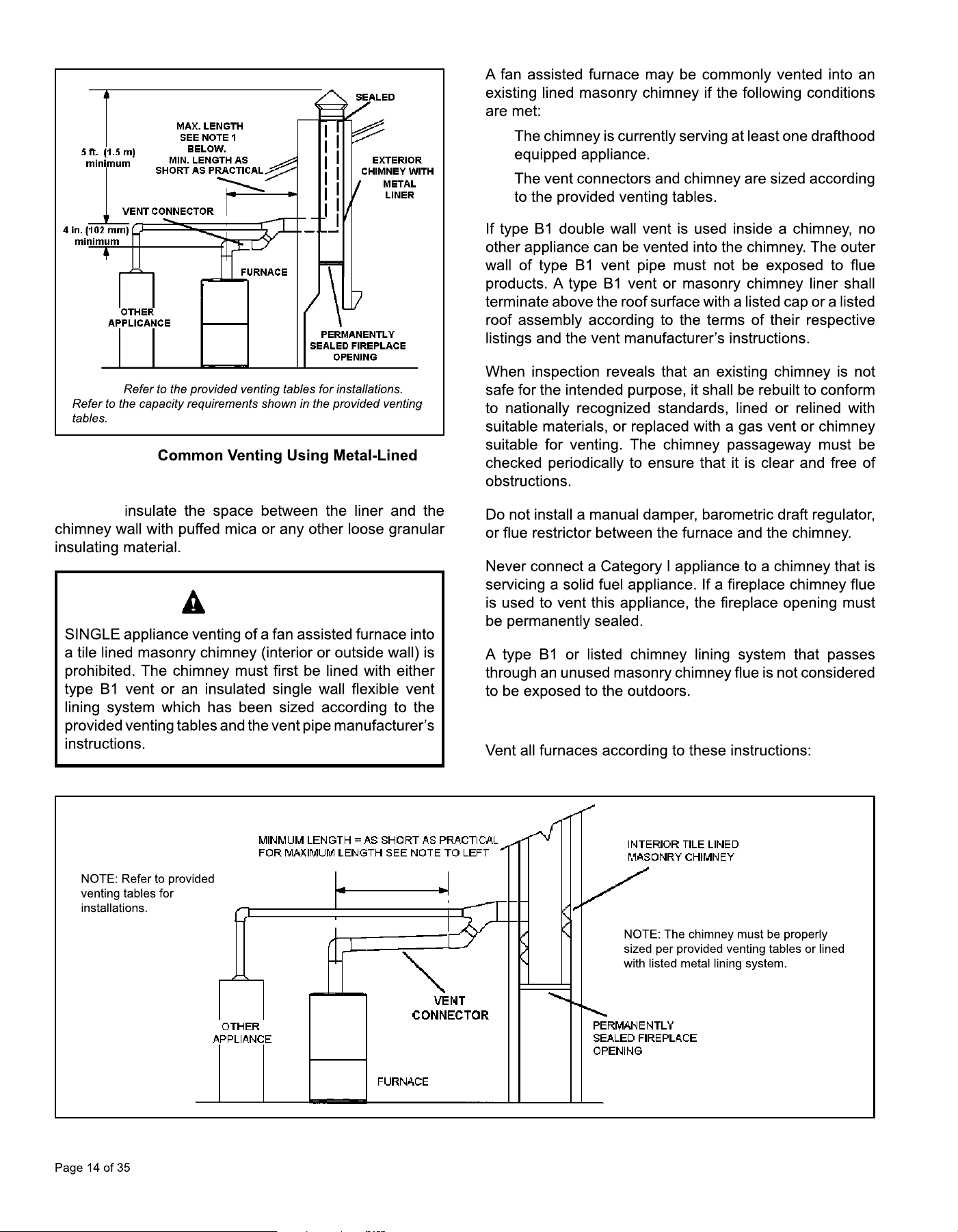
Venting Using a Masonry Chimney
507330-02Cmrcool.com
Figure 23.
Masonry Chimney
NOTE 1:
DO NOT
IMPORTANT
•
•
General Venting Requirements
Figure 24. Common Venting Using Tile Lined Interior Masonry Chimney and Combined Vent Connector
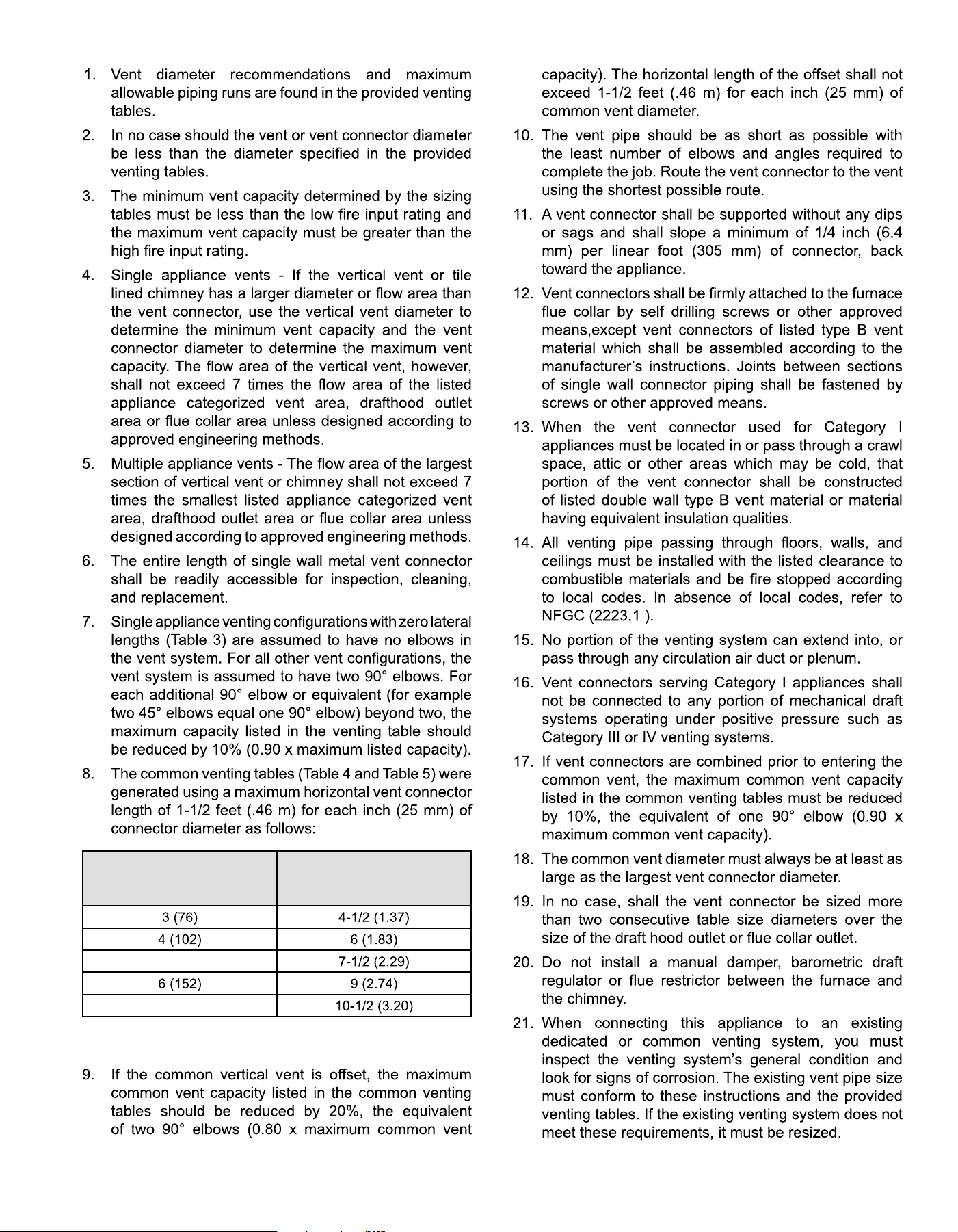
507330-02C mrcool.com Page 15 of 35
Table 2.
Connector Diameter
in. (mm)
Maximum Horizontal
Connector Length
ft. (m)
5 (127)
7 (178)
507330-02Cmrcool.com
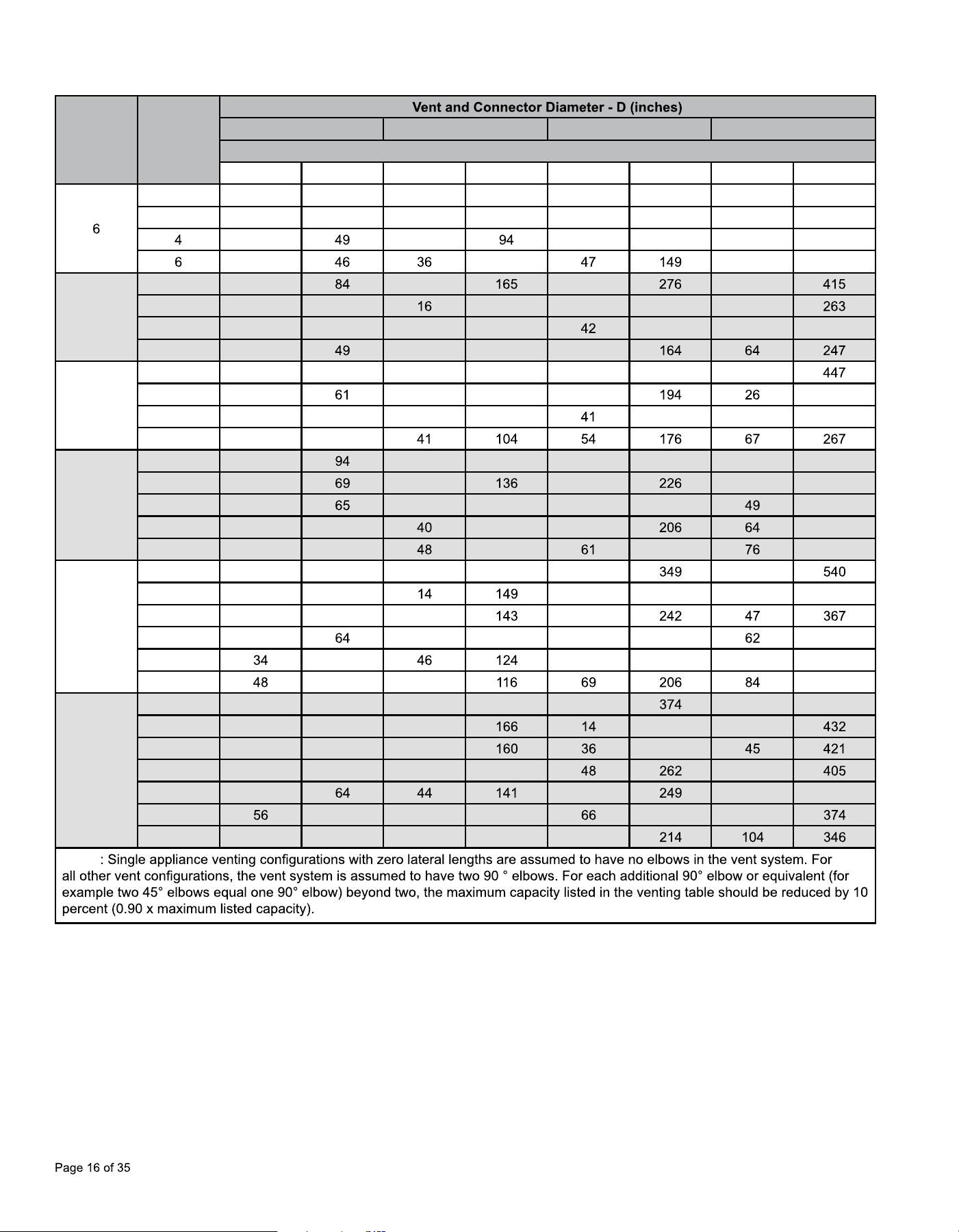
Table 3.
Capacity of Type B Double Wall Vents with Type B Double Wall Connectors Serving a Single Category I Appliance
Height
H
(feet)
Lateral
L
(feet)
3 inch 4 inch 5 inch 6 inch
Appliance Input Rating in Thousands of Btu per Hour
MIN MAX MIN MAX MIN MAX MIN MAX
0 0 78 0 152 0 251 0 375
2 13 51 18 97 27 157 32 232
21 30 39 153 50 227
25 91 59 223
8
0 0
0 0 0
2 12 57 109 25 178 28
5 23 53 32 103 171 53 255
8 28
39 98 51
10
0 0 88 0 175 0 295 0
2 12 17 118 23 289
5 23 57 32 113
187 52 280
10 30 51
15
0 0
0 191 0 327 0 502
2 11
15 20 22 339
5 22
30 130 39 219 330
10 29 59
121 51 315
15 35 53
112 195 301
20
0 0 97 0 202 0
0
2 10 75 18 250 20 377
5 21 71 29
38
10 28 38 133 50 229 351
15
58 59 217 73 337
20
52 55 322
30
0 0 100 0 213 0
0 587
2 9 81 13
283 18
5 21 77 28 275
10 27 70 37 150 59
15 33 57 70 389
20
58 53 132 237 80
30 NR NR 73 113 88
NOTE
507330-02C mrcool.com Page 17 of 35
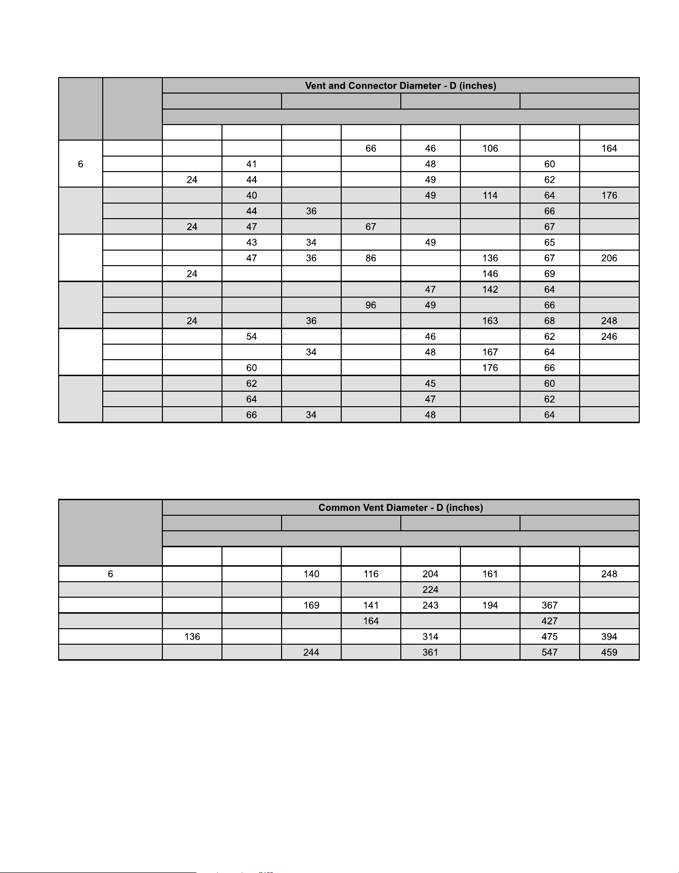
Vent Connector Capacity
Type B Double Wall Vents with Type B Double Wall Connectors Serving Two or More Category I Appliances
Vent
Height
H
(feet)
Connector
Rise
R
(feet)
3 inch 4 inch 5 inch 6 inch
Appliance Input Rating in Thousands of Btu per Hour
MIN MAX MIN MAX MIN MAX MIN MAX
1 22 37 35 58
2 23 37 75 121 183
3
38 81 132 199
8
1 22
35 72
2 23 80 51 128 195
3
37 53 139 210
10
1 22
78 123 189
2 23
51
3 50 37 92 52 220
15
1 21 50 33 89
220
2 22 53 35
153 235
3
55 102 51
20
1 21
33 99 157
2 22 57 105 259
3 23
35 110 50 271
30
1 20
31 113 181 288
2 21
33 118 190 299
3 22
123 198 309
Table 4.
Common Vent Capacity
Type B Double Wall Vents with Type B Double Wall Connectors Serving Two or More Category I Appliances
Vent Height
H
(feet)
4 inch 5 inch 6 inch 7 inch
Appliance Input Rating in Thousands of Btu per Hour
FAN + FAN FAN + NAT FAN + FAN FAN + NAT FAN + FAN FAN + NAT FAN + FAN FAN + NAT
92 81 309
8 101 90 155 129 178 339 275
10 110 97
299
15 125 112 195
283 228 352
20
123 215 183 255
30 152 138 210 297
Table 5.
507330-02CPage 18 of 35 mrcool.com
Removal of the Furnace from Common Vent
CARBON MONOXIDE POISONING HAZARD
WARNING
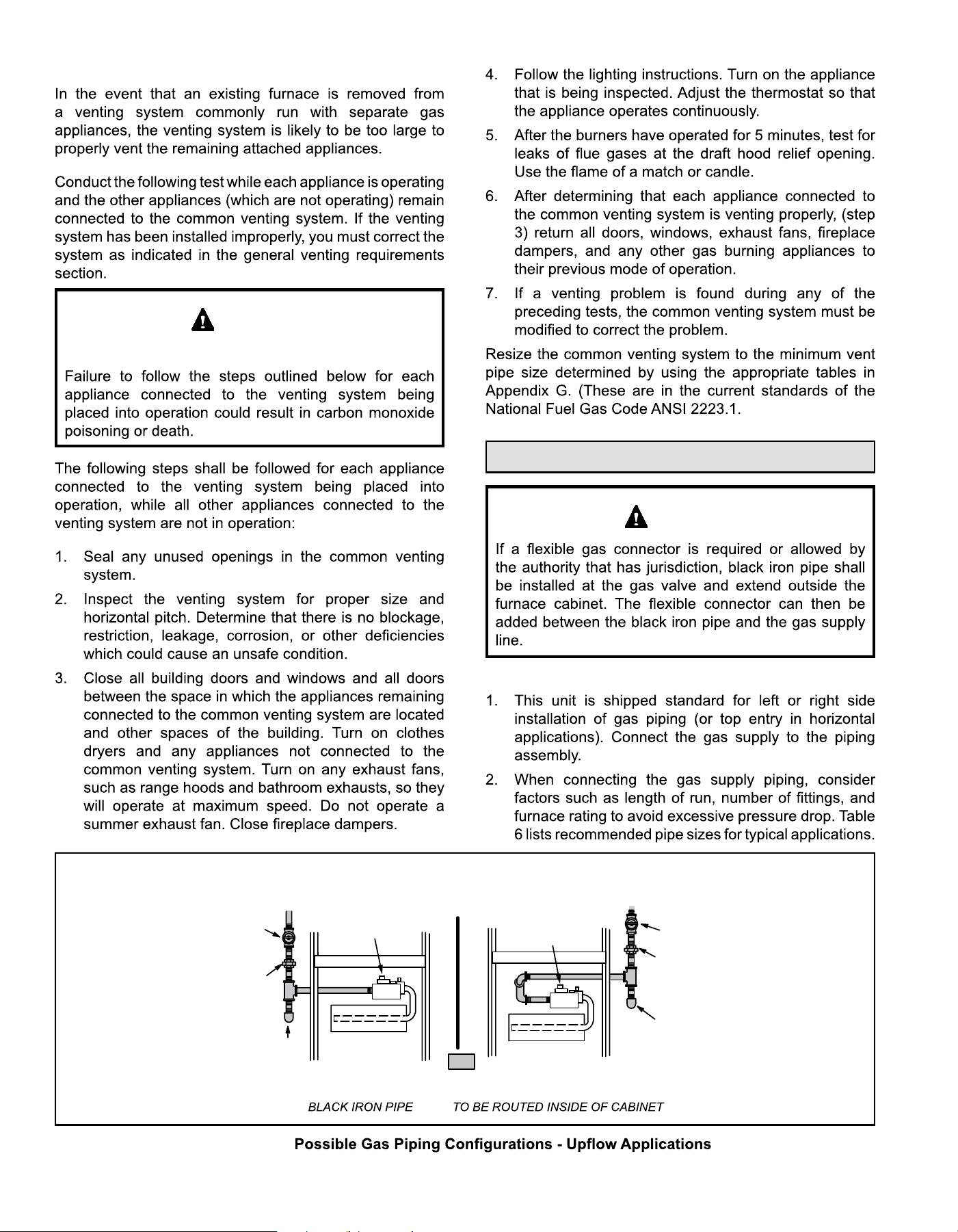
Gas Piping
CAUTION
Gas Supply
FIELD
PROVIDED
AND INSTALLED
Left Side Piping
(Standard)
Right Side Piping
(Alternate)
GROUND
JOINT
UNION
DRIP LEG
MANUAL
MAIN SHUT-OFF
VALVE
AUTOMATIC
GAS VALVE
(with manual
shut-off valve)
GROUND
JOINT
UNION
DRIP LEG
MANUAL
MAIN SHUT-OFF
VALVE
AUTOMATIC
GAS VALVE
(with manual
shut-off valve)
NOTE: ONLY
Figure 25.
507330-02C mrcool.com Page 19 of 35
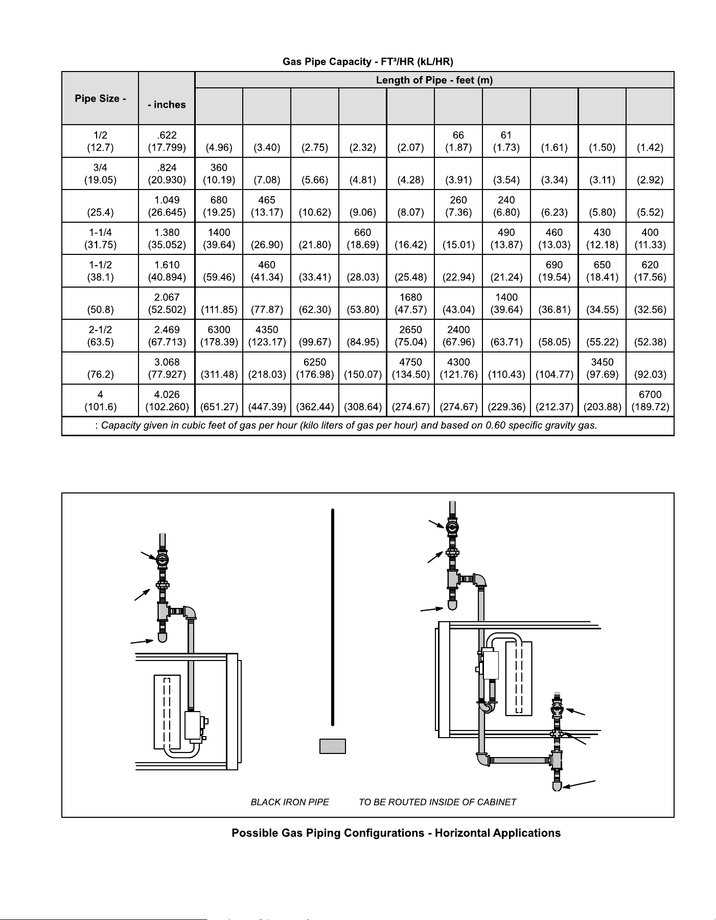
Table 6.
Nominal Iron
inches (mm)
Internal
Diameter
(mm)
10
(3.048)
20
(6.096)
30
(9.144)
40
(12.192)
50
(15.240)
60
(18.288)
70
(21.336)
80
(24.384)
90
(27.432)
100
(30.480)
175 120 97 82 73 57 53 50
250 200 170 151 138 125 118 110 103
1 375 320 285 220 205 195
950 770 580 530
2100 1180 990 900 810 750
2 3950 2750 2200 1900 1520 1300 1220 1150
3520 3000 2250 2050 1950 1850
3 11000 7700 5300 3900 3700 3250
23000 15800 12800 10900 9700 9700 8100 7500 7200
NOTE
Figure 26.
GROUND
JOINT
UNION
DRIP LEG
MANUAL
MAIN SHUT-OFF
VALVE
GROUND
JOINT
UNION
DRIP LEG
MANUAL
MAIN SHUT-OFF
VALVE
GROUND
JOINT
UNION
DRIP LEG
MANUAL
MAIN SHUT-OFF
VALVE
Horizontal Application
Left-Side Air Discharge
Horizontal Application
Right-Side Air Discharge
FIELD
PROVIDED
AND INSTALLED
NOTE: ONLY
507330-02CPage 20 of 35 mrcool.com
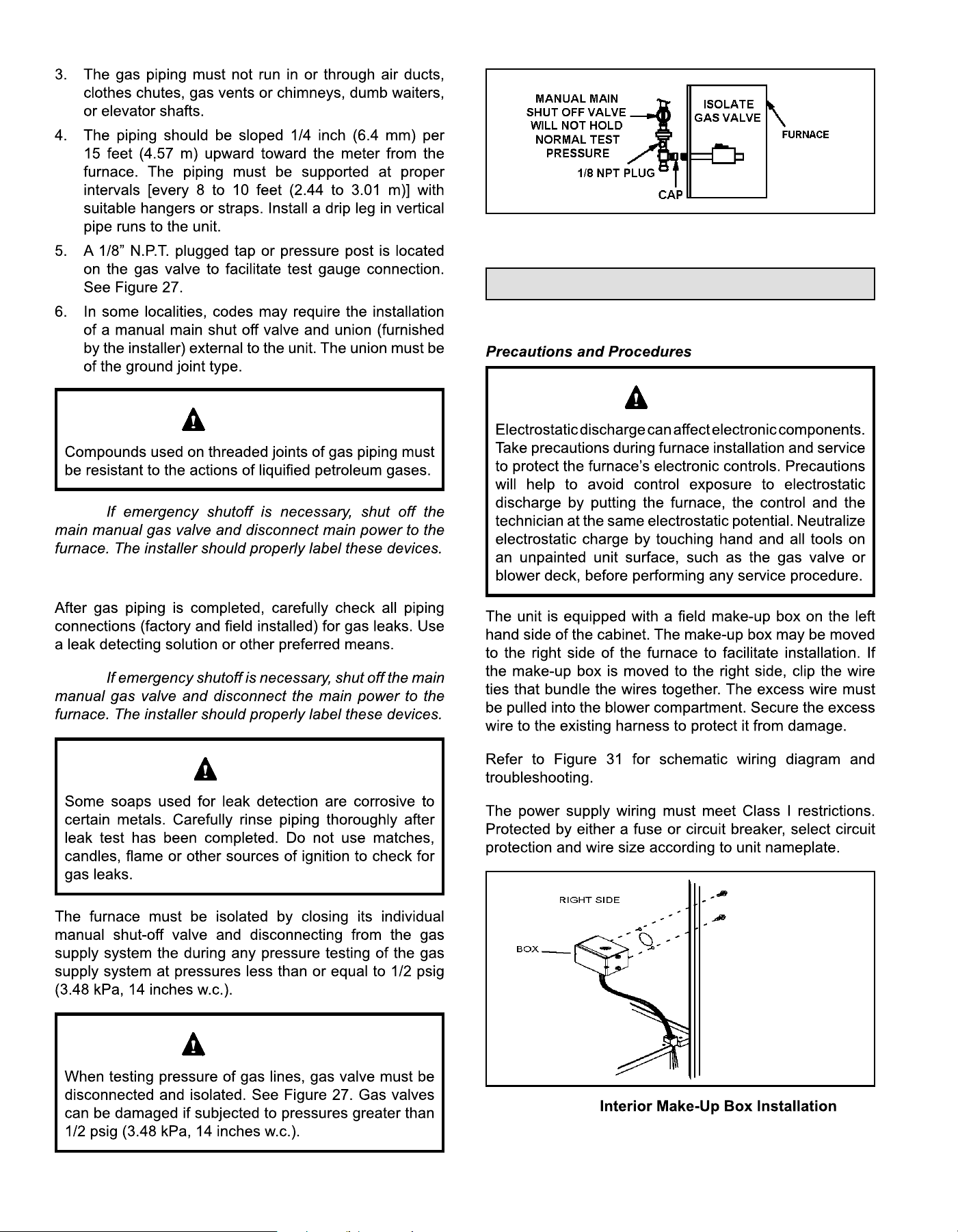
IMPORTANT
NOTE:
Leak Check
NOTE:
CAUTION
IMPORTANT
Figure 27.
Electrical
ELECTROSTATIC DISCHARGE (ESD)
CAUTION
Figure 28.
507330-02C mrcool.com Page 21 of 35
Figure 29.
NOTE:
NOTE:
Accessory Terminals
•
•
•
•
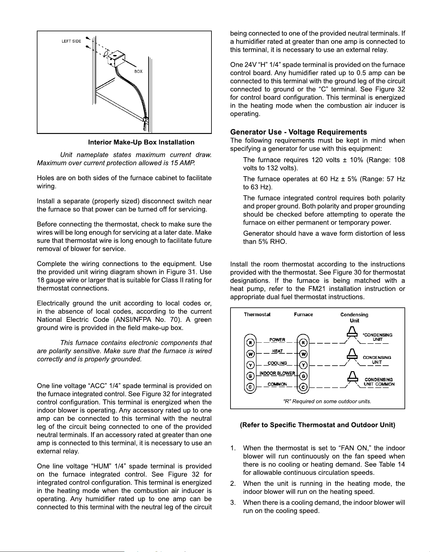
Thermostat
Figure 30. Condensing Unit Thermostat Designations
* Note:
Indoor Blower Speeds
507330-02CPage 22 of 35 mrcool.com
E045A3
E070B3
E090B4
E090C5
E110C5
E135D5
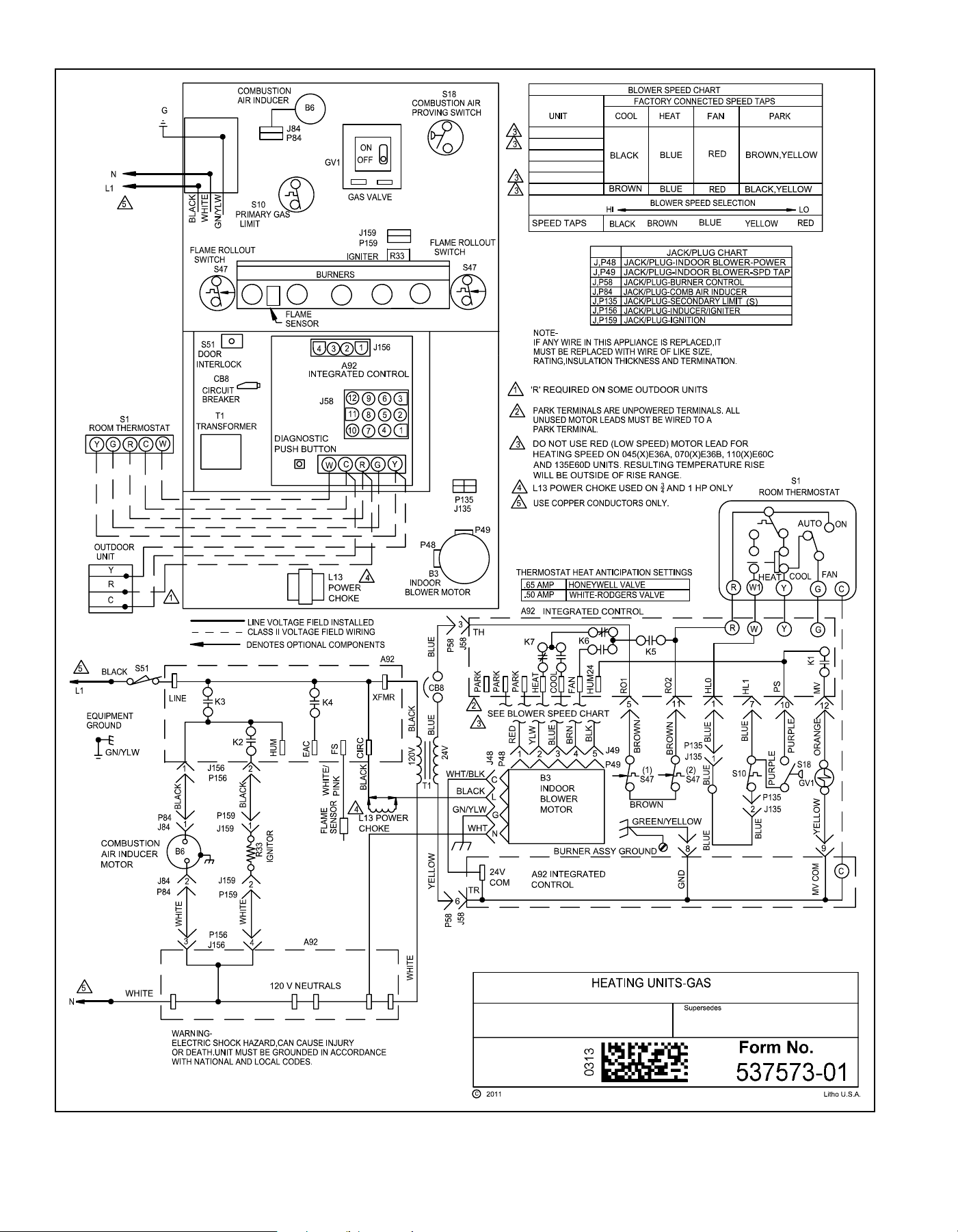
Figure 31. Wiring Diagram
507330-02C mrcool.com Page 23 of 35
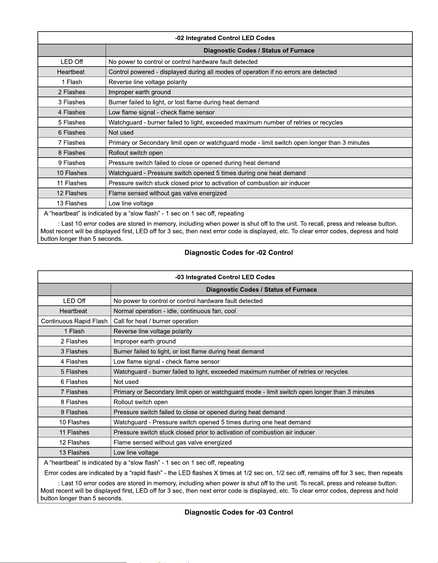
Table 7.
Red LED Flash Code
1
1
NOTE
Table 8.
Red LED Flash Code
2
1
1
2
NOTE
507330-02Cmrcool.com
FOR YOUR SAFETY, READ BEFORE LIGHTING UNIT
WARNING
WARNING
CAUTION
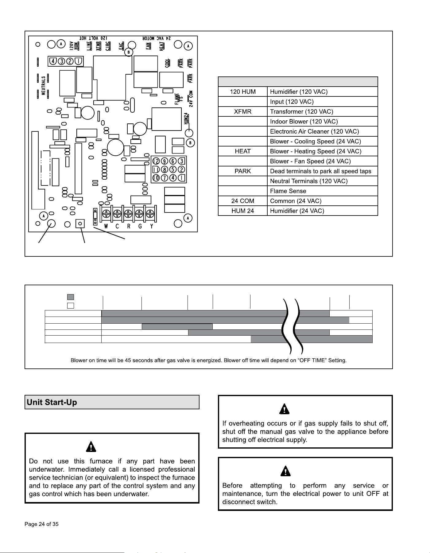
Figure 32. Integrated Control
(Automatic Hot Surface Ignition System)
Terminal Designations
LINE
CIRC
EAC
COOL
FAN
NEUTRALS
FS
RED LED
RECALL BUTTON
BLOWER OFF DELAY
Figure 33. Heating Sequence of Operation
Demand
15
ON
OFF
CAI
35
1
Pre-Purge
Ignitor Warm-up
Blower
“On” Delay
Post
Purge
5 SEC80
Ignitor
Gas Valve
Indoor Blower
39
Trial for
Ignition
507330-02C mrcool.com Page 25 of 35
BEFORE LIGHTING
Placing the Furnace into Operation
WARNING
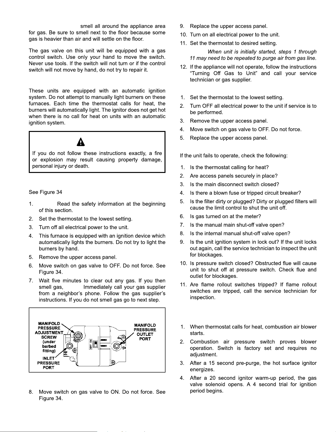
Gas Valve Operation
STOP!
STOP!
Figure 34.
Gas Valve Shown in “ON” Position
NOTE:
Turning Off Gas to Unit
Failure to Operate
Heating Sequence of Operation
See Figure 33
507330-02Cmrcool.com
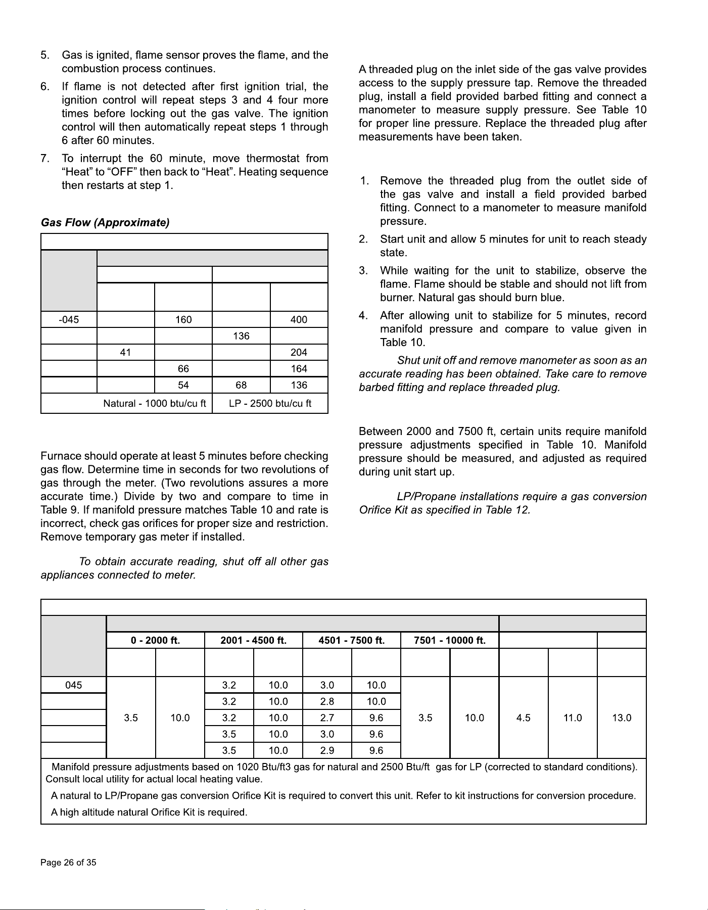
Gas Pressure Adjustment
Gas Meter Clocking Chart
Capacity
Seconds for One Revolution
Natural LP
1 cu ft
Dial
2 cu ft
Dial
1 cu ft
Dial
2 cu ft
Dial
80 200
-070 55 110 272
-090
82 102
-110 33 82
-135 27
Table 9.
NOTE:
Supply Pressure Measurement
Manifold Pressure Measurement
NOTE:
Manifold Pressure
NOTE:
Manifold Pressure and Line Pressure at Various Altitudes
Capacity
Manifold Pressure (in. w.c.)
1
Line Pressure (in. w.c.)
Minimum Max.
Nat.
Gas
LP
Gas
2
Nat.
Gas
LP
Gas
2
Nat.
Gas
LP
Gas
2
Nat.
Gas
3
LP
Gas
2
Nat.
Gas
LP
Gas
2
Nat. &
LP
070
090
110
135
1 3
2
3
Table 10.
507330-02C mrcool.com Page 27 of 35
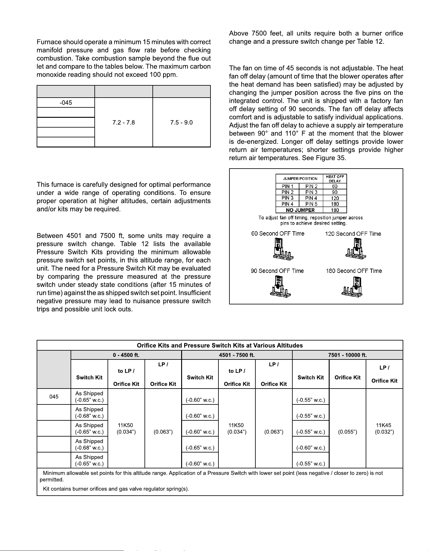
Proper Combustion
Capacity CO
2
% for Nat CO
2
% for LP
-070
-090
-110
-135
Table 11.
High Altitude
Pressure Switch
Fan Control
Figure 35. Heat Fan Off Time in Seconds
Capacity
Pressure
1
Natural
Propane
Propane
to Natural
Pressure
1
Natural
Propane
Propane
to Natural
Pressure
1
Natural
Propane
2
73W80
2
80W52
2
73W80
2
80W51
51W01
2
070
80W52 80W51
090
80W52 80W51
110
80W57 80W52
135
80W52 80W51
1
2
Table 12.
507330-02CPage 28 of 35 mrcool.com
Constant Torque Motor
Thermostat Heat Anticipation
NOTE:
Electrical
Blower Speeds
NOTE:
Other Unit Adjustments
507330-02C mrcool.com Page 29 of 35
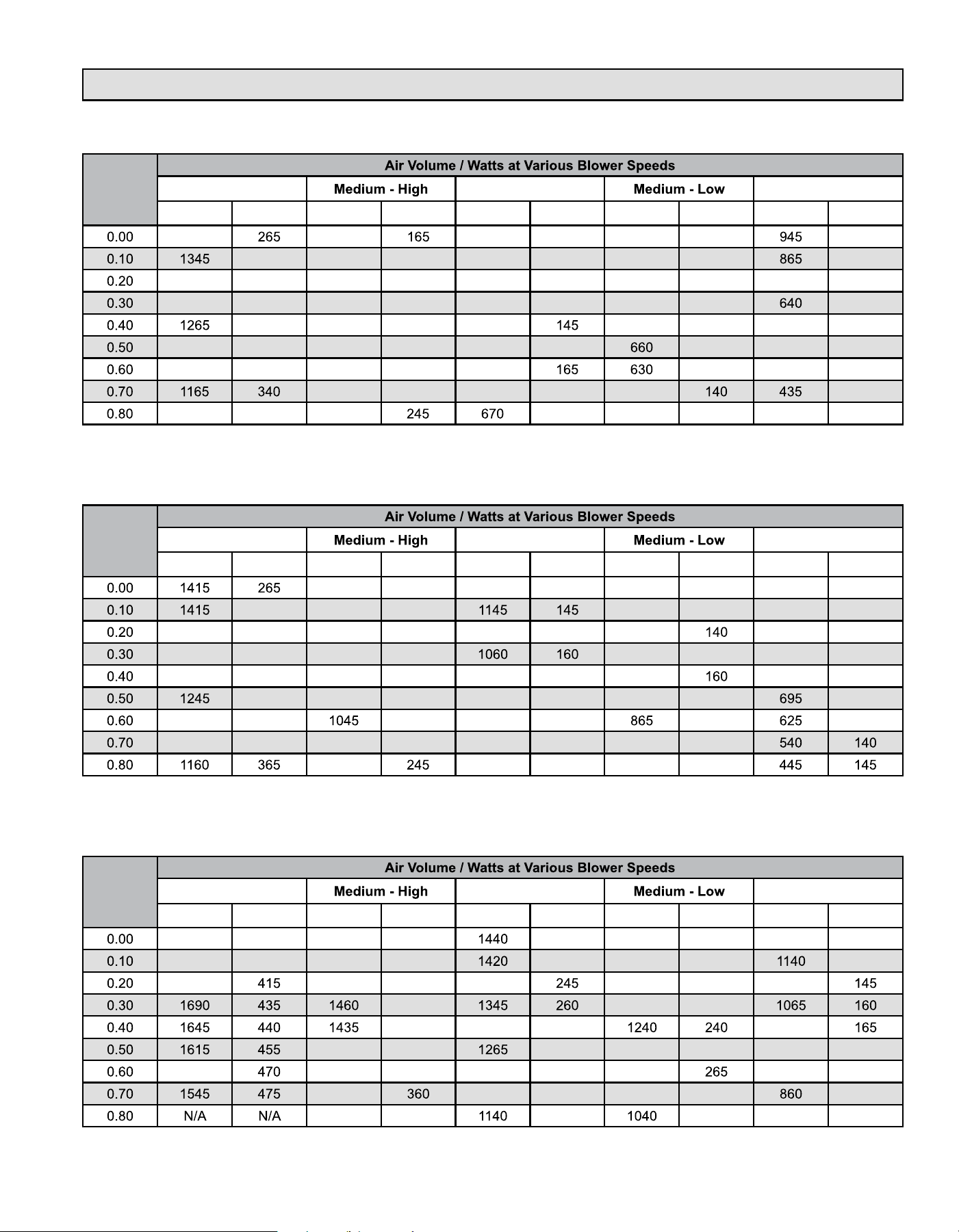
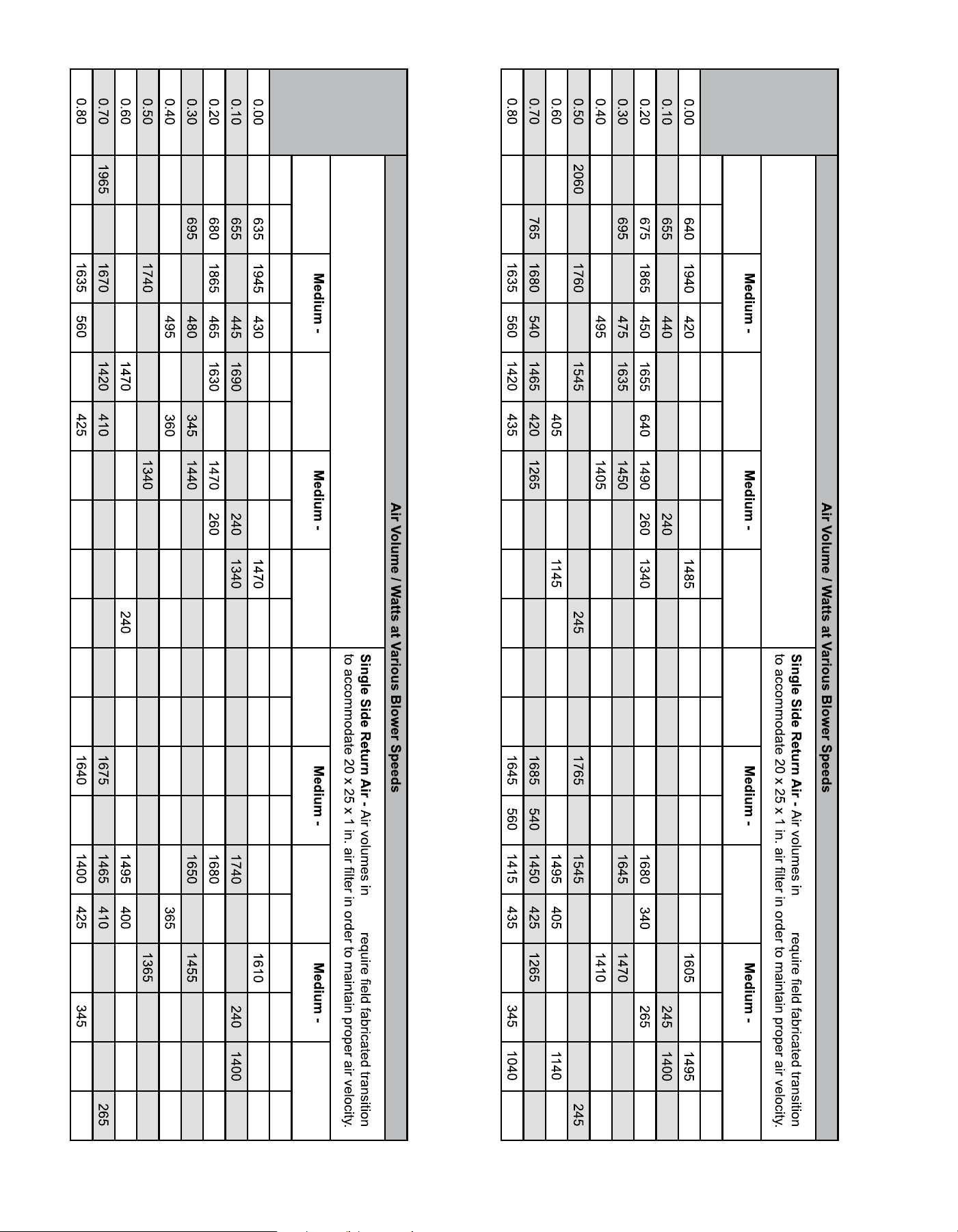
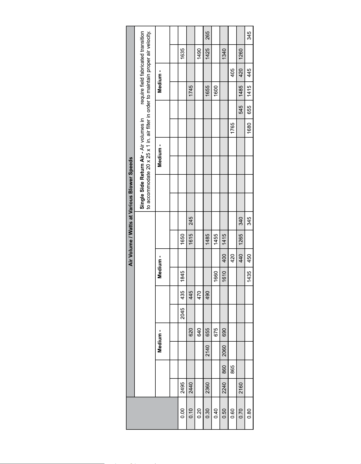
Blower Performance
MGM80SE045A3A Performance (Less Filter)
External
Static
Pressure
in. w.c.
High Medium Low
cfm watts cfm watts cfm watts cfm watts cfm watts
1380 1155 995 120 975 115 105
270 1120 175 950 120 880 105 100
1320 285 1080 190 900 125 805 105 700 85
1290 295 1055 200 875 135 750 110 90
310 1010 205 825 710 120 595 95
1230 315 990 215 790 155 125 535 100
1190 330 990 230 750 135 500 100
915 235 705 170 570 115
1130 350 880 180 535 150 380 120
MGM80SE070B3A Performance (Less Filter)
External
Static
Pressure
in. w.c.
High Medium Low
cfm watts cfm watts cfm watts cfm watts cfm watts
1330 170 1215 135 1175 125 1075 85
280 1295 170 1130 130 955 95
1355 290 1225 185 1110 150 1080 885 100
1330 300 1190 200 1035 155 825 110
1290 310 1155 205 1015 175 970 770 120
325 1115 215 980 180 930 170 125
1225 335 230 920 190 180 135
1190 350 1000 235 855 205 790 190
925 790 205 735 200
MGM80SE090B4A Performance (Less Filter)
External
Static
Pressure
in. w.c.
High Medium Low
cfm watts cfm watts cfm watts cfm watts cfm watts
1785 380 1570 270 220 1395 190 1190 125
1755 395 1535 275 230 1350 205 135
1730 1505 290 1380 1310 215 1110
305 1275 230
320 1310 270 1010
1395 335 285 1180 255 955 175
1590 1350 350 1210 290 1150 915 190
1300 1175 305 1095 275 200
1270 370 310 285 820 210
507330-02CPage 30 of 35 mrcool.com
MGM80SE110C5A Performance (Less Filter)
External
Static
Pressure
in. w.c.
Bottom Return Air, Side Return Air with Optional Return Air Base, Return
Air from Both Sides or Return Air from Bottom and One Side.
bold
High
High
Medium
Low
Low High
High
Medium
Low
Low
cfm watts cfm watts cfm watts cfm watts cfm watts cfm watts cfm watts cfm watts cfm watts cfm watts
2230
1715 295 1555 230 185 2315 645 1990 415 1780 300
230 1510 200
2180
1905
305 1510 175 2260 655 1945 425 315 1550 185
2135 330
1280 190 2210 680 1895 460
335 1510 255 1350 200
2090
1830
1595
275 1235 200 2165 700 1850 465
355
275 1285 210
2050 715 1785
1550
1385 285 1175 210 2135 715 1830 485 1585 1395 285 1230 225
2025 730
520 1500 375
300 1130 225 2095 730 1770 500 1535 385 300 1175 235
2010 750 1710 535 390 1305 320 1080 2055 755 1725 515
1305 315 1135 250
755
555
1255 330 1015 255 2000 765 535 1255 325 1080
1905 785
1380
1215 350 975 270 1965 785
555
1210
1025 275
MGM80SE090C5A Performance (Less Filter)
External
Static
Pressure
in. w.c.
Bottom Return Air, Side Return Air with Optional Return Air Base, Return
Air from Both Sides or Return Air from Bottom and One Side.
bold
High
High
Medium
Low
Low High
High
Medium
Low
Low
cfm watts cfm watts cfm watts cfm watts cfm watts cfm watts cfm watts cfm watts cfm watts cfm watts
2255
1750 310 1580 230 185 2290 655 1980 425 1775 310
235
195
2200
1910
1705 315 1535 1385 190 2250 675 1945 445 1730 320 1555 190
2150
205 2210 695 1885 465
1510
1350 205
2125
1835
355
275 1285 215 2165 715 1850 475
355
275 1285 215
2090 715 1800
1585 370 285 1235 230 2135 720 1810 490 1595 370 290 1225 230
735
510
385 1370 305 1200 2070 735
515
390 1370 305 1180
2020 750 1725 525 1515
1320 320
255 2030 760 1715 530
1325 320
255
1980
330 1105 270 1990 775 330 1095 270
1935 785 1225 350 1055 285 1950 795 1225
285
507330-02C mrcool.com Page 31 of 35
MGM80SE135D5A Performance (Less Filter)
External
Static
Pressure
in. w.c.
Bottom Return Air, Side Return Air with Optional Return Air Base, Return
Air from Both Sides or Return Air from Bottom and One Side.
bold
High
High
Medium
Low
Low High
High
Medium
Low
Low
cfm watts cfm watts cfm watts cfm watts cfm watts cfm watts cfm watts cfm watts cfm watts cfm watts
755 2295 590 315 230 2365 725 2295 575 2005 410 1820 300 235
780 2220 2015 1820 330 2350 745 2210 595 2000 435
320 1530 230
2390 790 2175
1935 1735 350 1550 255 2330 775 2175 625 1945 455 1730 330 250
805 1895 1720 370 275 2245 785 2135 645 1895 475
355
2285 835 2125 1850 510 380 290 2215 810 2085 660 1840 495 375 1385 285
1815 535 310 2175 825 2045 680 1815 505 1590 390 290
2225 2015 715 1785 550 1535 1330 320 2125 845 1995 700 530 1525 1300 310
895 1955 735 1755 570 1500 2095 865 1950 710 1700
325
2105 905 1925 750 1715 580
1215
2065 880 1880 725
1205
507330-02CPage 32 of 35 mrcool.com
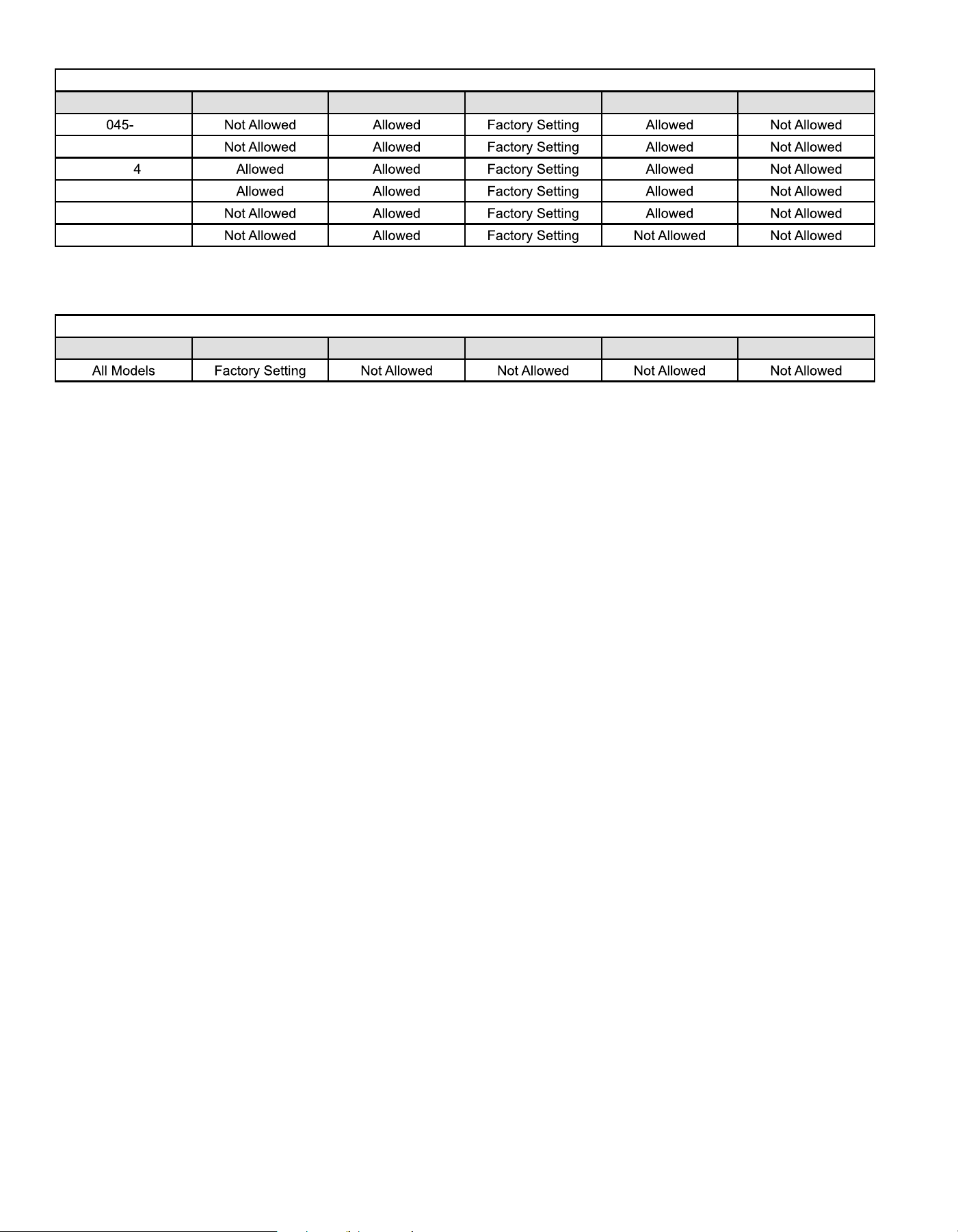
Allowable Heating Speeds
Models Red Yellow Blue Brown Black
3
070-3
090-
090-5
110-5
135-5
Table 13.
Allowable Circulation Speeds
Models Red Yellow Blue Brown Black
Table 14.
507330-02C mrcool.com Page 33 of 35
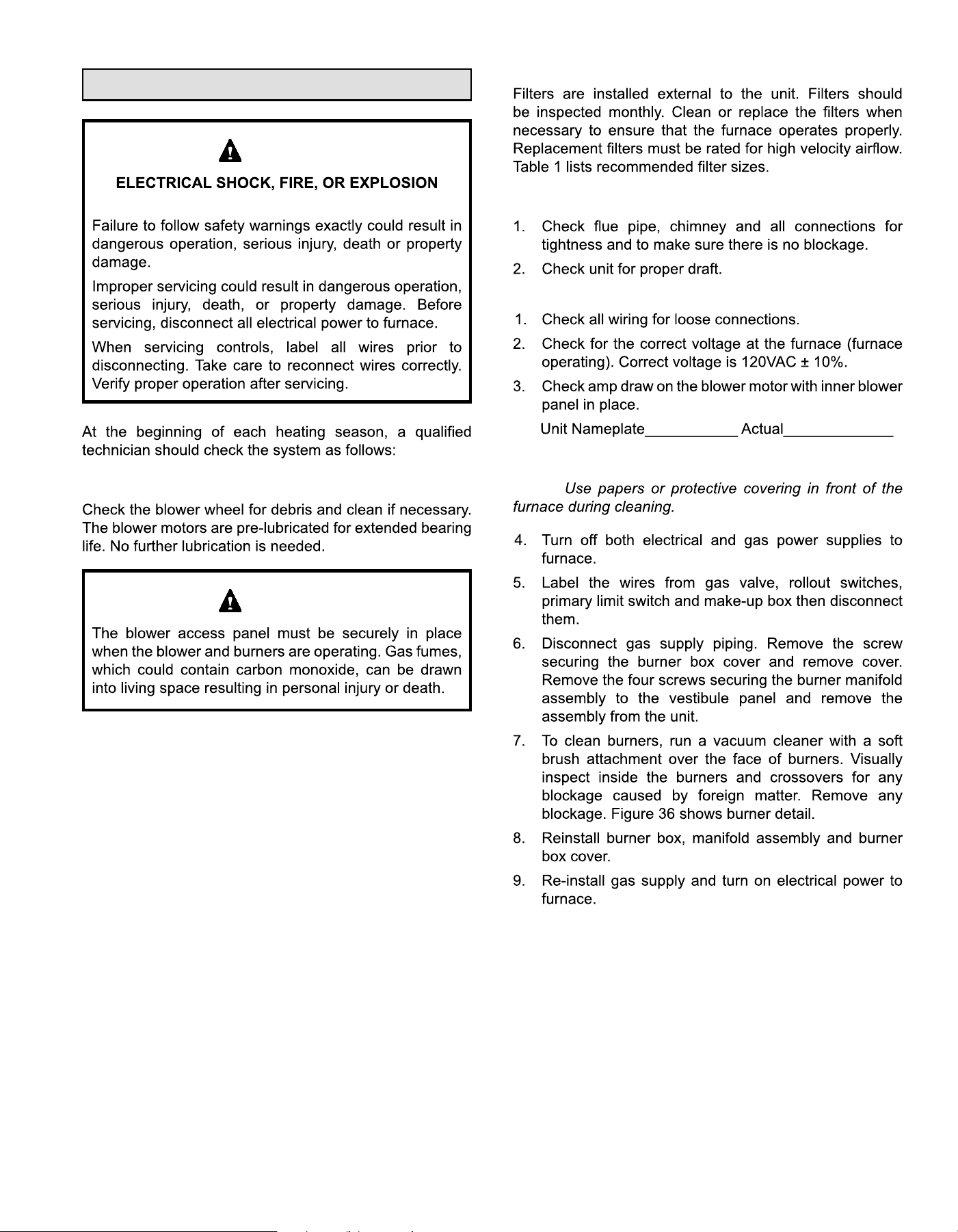
Service
HAZARD.
WARNING
Blower
WARNING
Filters
Flue and Chimney
Electrical
Cleaning the Burners
NOTE:
507330-02Cmrcool.com
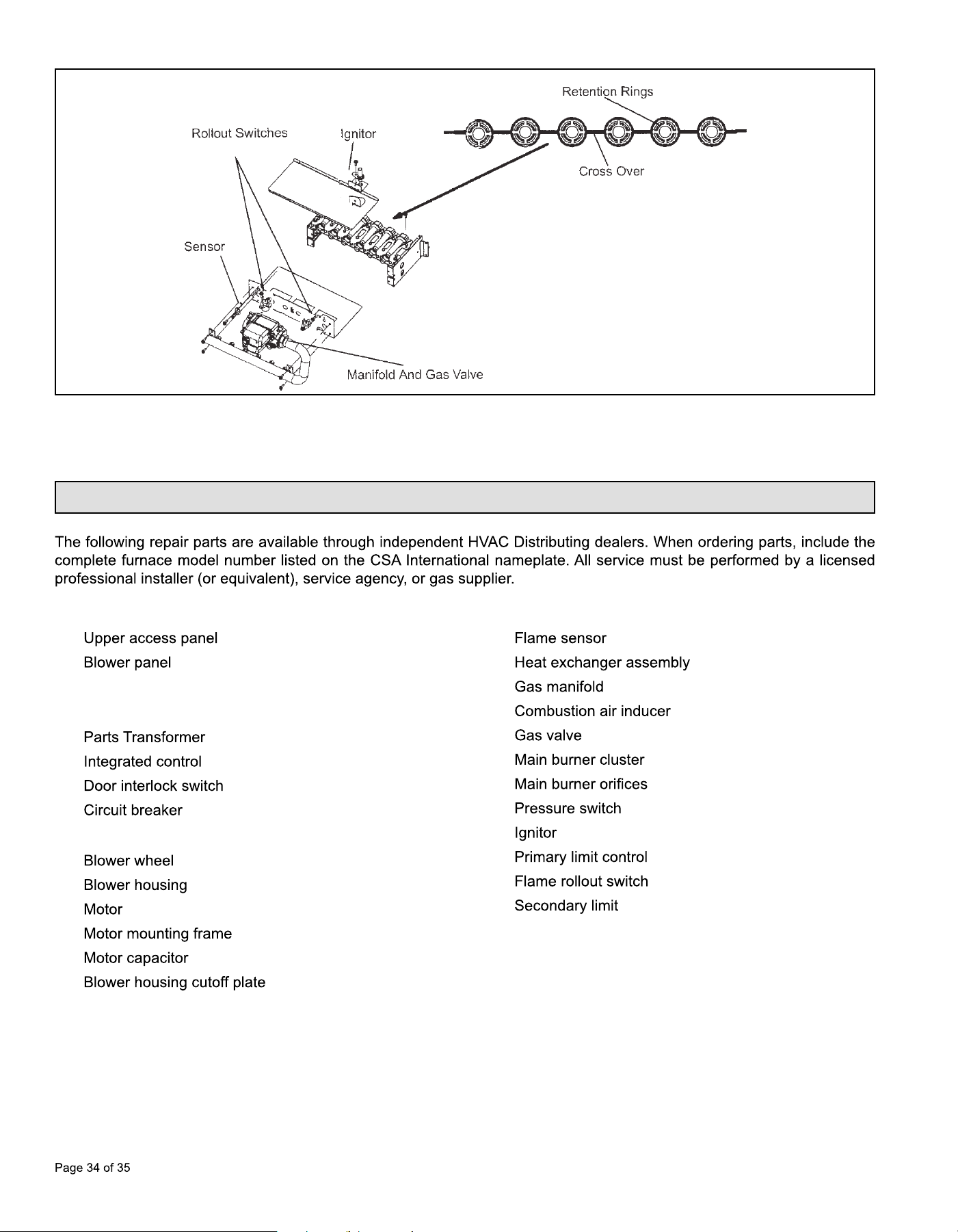
Figure 36. Burner Assembly Removal
Repair Parts List
Cabinet Parts
•
•
• Top cap
Control Panel
•
•
•
•
Blower Parts
•
•
•
•
•
•
Heating Parts
•
•
•
•
•
•
•
•
•
•
•
•
507330-02C mrcool.com Page 35 of 35
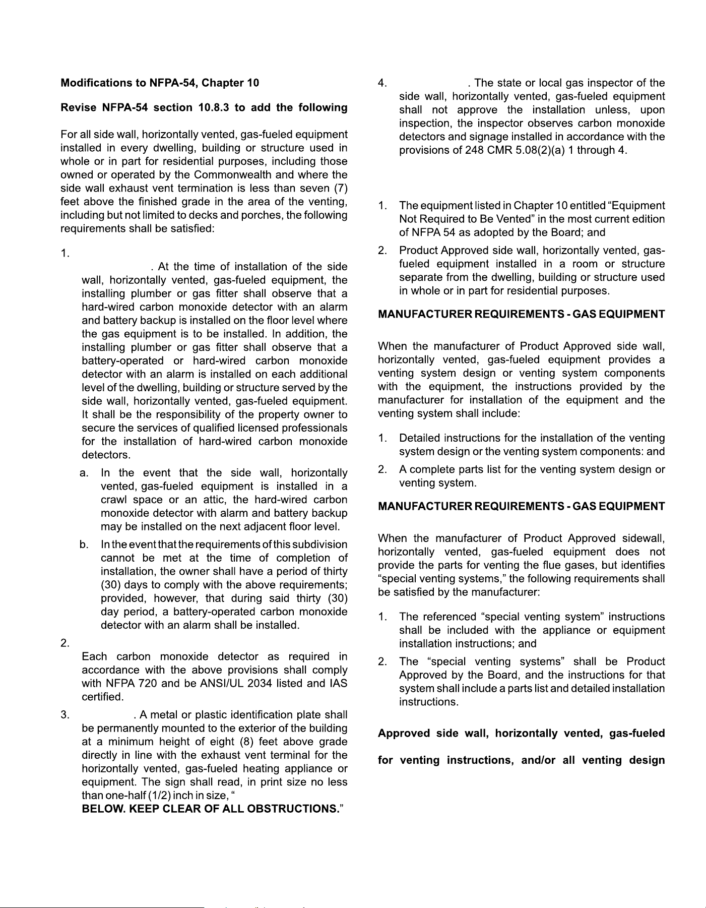
Requirements for Commonwealth of Massachusetts
requirements:
INSTALLATION OF CARBON MONOXIDE
DETECTORS
APPROVED CARBON MONOXIDE DETECTORS.
SIGNAGE
GAS VENT DIRECTLY
INSPECTION
EXEMPTIONS: The following equipment is exempt
from 24 CMR 5.08(2)(a) 1 through 4:
VENTING SYSTEM PROVIDED.
VENTING SYSTEM NOT PROVIDED.
A copy of all installation instructions for all Product
equipment, all venting instructions, all parts lists
instructions shall remain with the appliance or
equipment at the completion of the installation.

The design and specifications of this product and/or manual are subject to change without prior notice.
Consult with the sales agency or manufacturer for details.
Signature Series
MGM80*SE*XA Warm Air Gas Furnace
ELECTRICIAN and/or HVAC TECHNICIAN:
LICENSE #:
INSTALLATION DATE:
INSTALLATION LOCATION:
SERIAL NUMBER: