
Radio Activity S.r.l.
Via privata Cascia, 11 - 20128 Milano- Italy – email: comm@radioactivity-tlc.it - www.radioactivity-tlc.com
Tel. +39.02.36514205 - FAX/Voicebox +39.1782.242408 - CCIAA Milano N° 1728248 - VAT Id. 04135130963
KAIROS enhanced User Manual
Version 1.1

Radio Activity S.r.l. 2 / 37
Summary
1 FOREWORD ..................................................................................................................................... 7
1.1 LOCAL LAWS RESTRICTIONS ........................................................................................................................ 7
1.2 DOCUMENT COPYRIGHTS .......................................................................................................................... 7
1.3 DISCLAIMER ............................................................................................................................................ 7
1.4 MODIFICATIONS ...................................................................................................................................... 7
2 PRODUCT SAFETY ............................................................................................................................ 8
2.1 RF EXPOSURE COMPLIANCE ...................................................................................................................... 8
2.2 IMPROPER USE ........................................................................................................................................ 9
2.3 POWER SUPPLY ....................................................................................................................................... 9
2.4 ANTENNA SYSTEM / LIGHTNING .................................................................................................................. 9
3 RADIO DESCRIPTION ...................................................................................................................... 10
3.1 FRONTAL PANEL .................................................................................................................................... 10
3.2 REAR PANEL .......................................................................................................................................... 12
3.2.1 RX inputs specifications ............................................................................................................. 12
3.2.2 TX output specifications ............................................................................................................. 14
3.2.3 GPS antenna .............................................................................................................................. 15
3.2.4 Power supply .............................................................................................................................. 18
3.2.5 I/O ports ..................................................................................................................................... 19
4 INSTALLATION AND MAINTENANCE ............................................................................................... 22
4.1 IMPROPER USE ...................................................................................................................................... 22
4.2 THERMAL DISSIPATION............................................................................................................................ 22
4.3 POWER SUPPLY SYSTEM .......................................................................................................................... 23
4.4 ANTENNA ............................................................................................................................................. 23
4.4.1 Maximum permitted antenna gain for mobile usage ................................................................ 23
4.4.2 Maximum permitted antenna gain for fixed usage ................................................................... 24

Radio Activity S.r.l. 3 / 37
4.5 AF INTERFACE ....................................................................................................................................... 24
4.6 MANUAL SETTINGS ................................................................................................................................ 24
4.7 SELF-TEST PROCESS ................................................................................................................................ 24
4.8 PPS SIGNAL .......................................................................................................................................... 24
4.9 ON SITE CHECK LIST ................................................................................................................................ 24
4.10 IP DISCOVER ...................................................................................................................................... 26
4.11 PREVENTIVE MAINTENANCE ................................................................................................................ 26
5 PARAMETERS CONFIGURATION AND REMOTE CONTROL ................................................................ 27
5.1 GATEWAY FOR DIGITAL CONSOLE .............................................................................................................. 27
6 ENGINEERING SPECIFICATIONS ...................................................................................................... 28
6.1 KAE MAIN SPECIFICATIONS ...................................................................................................................... 28
6.2 RADIO FREQUENCY ................................................................................................................................. 29
6.2.1 Transmitter ................................................................................................................................ 29
6.2.2 Receiver ...................................................................................................................................... 29
6.3 IP INTERFACING ..................................................................................................................................... 30
6.3.1 LAN protocols ............................................................................................................................. 30
6.3.2 Ports and connectors ................................................................................................................. 30
6.3.3 LAN requirements ...................................................................................................................... 31
6.3.4 Codec VoIP ................................................................................................................................. 31
6.3.5 SNMP protocol ........................................................................................................................... 31
6.4 GPS/GLONASS ANTENNA ..................................................................................................................... 32
6.4.1 GPS/GLONASS antenna requirements ....................................................................................... 32
6.5 FREQUENCY BANDS ................................................................................................................................ 32
6.6 BRANCHING REQUIREMENTS .................................................................................................................... 33
6.6.1 TX to antenna duplex isolation requirements @10W TX RF power ........................................... 33
6.6.2 Suggested RX max input limits on unwanted signals ................................................................ 33
6.7 OTHER SPECIFICATIONS ........................................................................................................................... 33
6.7.1 Environmental parameters ........................................................................................................ 33

Radio Activity S.r.l. 4 / 37
6.7.2 Power supply .............................................................................................................................. 34
6.7.3 Mechanical characteristics ........................................................................................................ 34
6.7.4 Audio balanced interfaces ......................................................................................................... 34
7 REGULATIONS COMPLIANCE .......................................................................................................... 34
7.1 NOTICE FOR EC USERS ............................................................................................................................ 35
7.2 NOTICE FOR US USERS ............................................................................................................................ 36
7.3 NOTICE FOR CANADIAN USERS ................................................................................................................. 36

Radio Activity S.r.l. 5 / 37
KAIROS enhanced – User manual
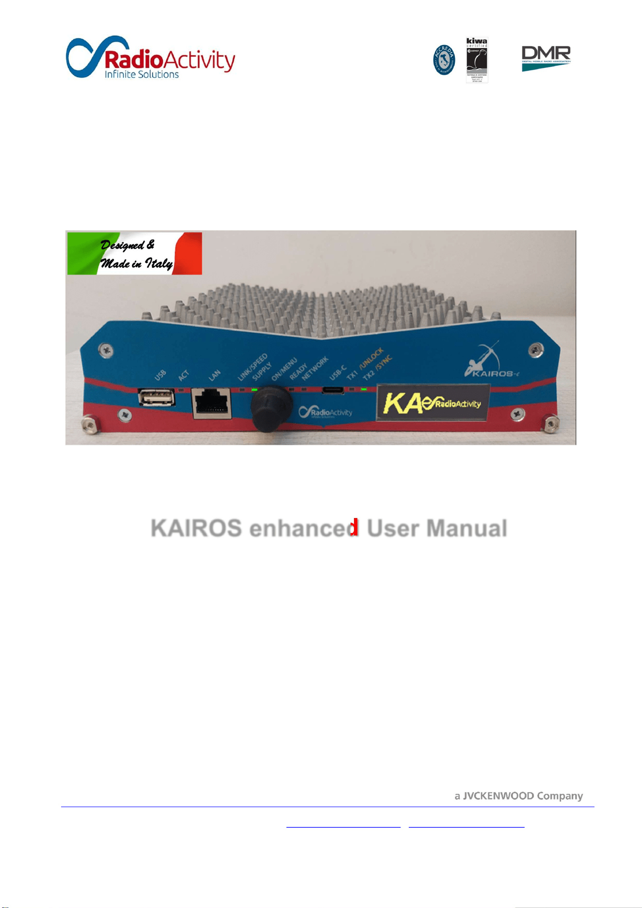
KAIROS enhanced (KAe) is an evolution of the KAIROS transceiver, which is present on the worldwide market
since 2014. The previous series has been completely renewed, in terms of components, performances and
applications and a new look has been designed, keeping the same overall shape of its previous model.
KAe transceiver is a professional software defined radio station, the right building block for a number of
applications ranging from a simple standalone repeater to a national wide network system, thanks to its
extreme flexibility. We solved the complexity to ease your creativity.
Main characteristics:
Available Models
Model
KA
-
080
KA
-
160
KA
-
040
KA
-
450
KA
-
500
KA
-
900
MHz 72-76
From
136 EU/
150 FCC/
138 ISED
to 174
39-50
406.1-
470
From 450
to 512
FCC /
470 ISED
806-941
Channelization
25/20/12,5/6,25 k
Hz
RF output power
1
-
5
0
W / 100% duty cycle / selectable per channel
Synthesis step
50Hz
Frequency stability
0,1 p.p.m.
Synchronization sources
Internal ref., GPS/GLONASS, Ethernet IEE
-
1588v2, 2 wire, Digital RX, External
Operating temperature
-
30°C ÷ +60°C
Power supply (negative
ground)
Min.
Typ.
Max.
1
0,8
V
13,6
V
15
,4
V
Power consumption
TX: 120 W @
5
0
W RF / RX:
6
W @Main+Div enabled
Dimensions & weight
160x200x45mm / 1.5
k
g
Audio lines
2x 4 wires + E&M
, RTP over IP
LAN port
Ethernet 10/100/1000
(auto MDI/MDI X) on an RJ45 socket
IP multisite bandwidth
70 kb/s in analog to/from Master
24 kb/s in DMR to/from Master (both DMR timeslots)

Radio Activity S.r.l. 6 / 37
Max tolerable IP delay
1080
ms (round trip)
Alarm
I/O
2xInput + 1
xOutput
Command
I/O
2xInput + 2
xOutput + 1xAnalog input

Radio Activity S.r.l. 7 / 37
1 Foreword
This manual is intended for use by experienced technicians familiar with RF and IP technology. It contains
information required for installation, setup and maintenance of a KAe based radio infrastructure.
1.1 Local laws restrictions
The use of this product is subjected to the local laws and in most cases requires a specific license. As example,
it may be prohibited in some RF bands or part of them, or may be limited in the RF power. Please, verify the
local law requirement before to use the equipment.
1.2 Document Copyrights
No distribution or duplication of this document or any portion of it shall take place without the express
written permission of Radio Activity. No part of this manual may be reproduced, distributed, or transmitted
in any form for any purpose without the express written permission of Radio Activity.
1.3 Disclaimer
The information in this document are carefully controlled, up-dated and are believed to be entirely reliable.
However, no responsibility is assumed for inaccuracies. Furthermore, Radio Activity reserves the right to
make changes to any products herein to improve readability, function, or design. Radio Activity does not
assume any liability arising out of the applications or use of any product or circuit described herein; nor does
it cover any license under its patent rights nor the rights of others.
1.4 Modifications
CAUTION: Changes or modifications not expressly approved by Radio Activity may void the user’s authority
to operate the equipment legally, as well as any warranty provided.

Radio Activity S.r.l. 8 / 37
2 Product Safety
2.1 RF Exposure Compliance
The device is intended for use in controlled / professional conditions in which users have full knowledge of
the level of exposure and can reduce it to meet the requirements of national and international regulations.
This device is not authorized for use by general people and consumers.
FCC Guidelines described in the OET Bulletin 65, state limits for maximum permissible exposure (MPE) and
specify the maximum power density for “General Population/Uncontrolled Exposure”.
This limit is:
In USA, according to FCC rules, 2 W/m² for VHF band (30-300 MHz); f/1500 for UHF band (300-1500
MHz), that is 3 W/m² at 500MHz.
In Canada, according to IC rules, 1.291 W/m² for VHF band (30-300 MHz); and f/1500 for UHF band
(300-1500 MHz), that is 3 W/m² at 500MHz.
It implies a constraint in terms of the minimum distance which people must keep from transmitting antenna,
in order to maintain the human exposure under the allowed limit.
With the assumption that a collinear omnidirectional antenna is used with a medium gain of 6dBi and that
the transmitter is set at 50W power (47dBm), it is possible to calculate the minimum distance of people from
the antenna by using the following equation for RF power decay in free space (far field):
S = ( P x G / 4 x π r
2
)
where:
S = maximum power density
P = maximum transmitted RF power
G = antenna gain
R = distance from antenna.
This gives:
r = ( P x G / S x 4 x π )
For VHF (39-50 MHz, 72-76 MHz and 150-174MHz) equipment the minimum safety distance is r = 2,8 m for
FCC and 3.5 m for ISED.
For UHF (407-470MHz) equipment the minimum safety distance is r = 2,3 m.
For further information on human RF exposure, contact your local health department. For example, Health
Canada’s Safety Code 6 provides a comprehensive set of guidelines.
For mobile usage, this transmitter must not be co-located or operating in conjunction with any other antenna
or transmitter.

Radio Activity S.r.l. 9 / 37
2.2 Improper use
The equipment is intended for use only in restricted access area. It is recommended to install the equipment
in closed cabinet, to allow only authorized people to access to them, in order to avoid handling or improper
use of equipment and to avoid accidental contact with hot surfaces.
This equipment is not suitable for use in rooms where children are likely to be present.
2.3 Power supply
The equipment requires a 13.6Vdc/10A, negative grounded, power supply. It is recommended to insert a 20A
fuse in the power supply cable near the power supply source (e.g.: a battery) to avoid dangerous damage
due to lightening event or to accidental short circuits along power supply cables.
The equipment is designed to be powered by a safe supply source which grants a double insulation of output
voltage from dangerous voltages. The electric plant must contain a switch to cut off power supply lines,
according to national law and directives.
Use only certified power supply devices and connect a ground cable to the GND Ø4MA nut to avoid lightning
and rescue problems. Remember that a lightning on the antenna system could pass the RF discharger arriving
to the chassis of the equipment. A robust GND cable short the energy preserving the other equipment in the
same site.
2.4 Antenna system / lightning
Providing adequate lightning protection is critical to a safe reliable communications site. Although KAe
embeds many protections, RF transmission cables, and AC and DC power lines must all be protected to
prevent excessive lightning energy from entering the site.
To reduce lightning problems, use lightning rod on the top of the radiating tower; anchor strongly the metallic
parts of the tower to the GND plane.
Insert, in coaxial cables coming from the antennas, adequate RF dischargers before to enter in the shelter
and connect them shortly to the extern GND plane.
Radio Activity S.r.l. 10 / 37
3 Radio description
KAe is a very sophisticated digital transceiver, target for high performance professional use.
Its architecture provides the capability of supporting a number of features resulting in a extremely flexible
two-way radio communications solution. Due to its flexibility, the complete parameters programming is not
an easy task. To perform a perfect programming to match the desired application, it is required a very skilled
and expert technician. Radio Activity strongly suggest to require a complete programming of the equipment
from Factory before the expedition.
In the following, we suppose that the equipment are already programmed for the application. Only the setup
of minor items will be described.
3.1 Frontal panel
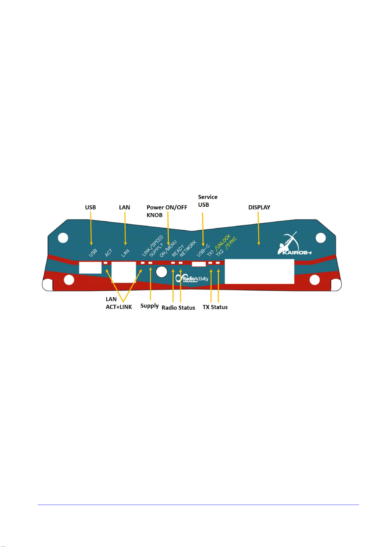
The following picture shows the frontal panel of KAIROS.
The frontal panel hosts:
1. 10/100/1000 Ethernet connector for the remote control of the equipment and for data/audio
packets communication;
2. USB port for optional additional devices for special purposes;
3. Micro USB for service aim only;
4. Knob with push button, in order to power on/off equipment and to select and confirm options on
the display; pressing this button once for 150ms to 4 seconds the equipment is powered on. To switch
off the equipment, press the button for at least 2 sec: the Radio Status led will start a RED fast blinking
for 2 sec to advise the user that the equipment is starting the shutdown procedure, then the blinking
becomes GREEN and slow to indicate that the equipment is ready to switch off. Now, releasing the
button, the equipment switches off. Note that the last on/off condition will be saved also in case of
power supply break therefore the equipment will automatically switch on after a black out.
5. Optional display for monitoring base parameters and selecting basic options.

Radio Activity S.r.l. 11 / 37
The frontal panel also hosts dual color LEDs for monitoring the status of the equipment:
∞ LAN Activity led; the LINK/SPEED led indicates the Ethernet signal presence and the Ethernet speed
(green = 10/100Mb/s, red=1000Mb/s), the ACT led indicates the LAN traffic.
∞ Supply led; when green it indicates that the equipment is correctly supplied. When the input voltage
is outside the equipment limits (too low or too high), this led becomes red. When off it indicates that
the equipment is switched off or an inverted polarity of power supply connection.
∞ Radio status led; the READY led becomes green when the LINUX O.S. and DSP are running correctly
and the equipment is ready for operation. The led NETWORK is:
o blinking slowly (1 sec) green when the equipment is correctly registered to its Master station
o blinking red when a Master station is defined but the equipment isn’t correctly registered to
it
o off when in standalone mode (e.g.: single repeater / mobile)
∞ TX status led; these led reports many run-time information about the status of the equipment. During
the regular functioning, Radio Led carry the following information:
Led
Status
TX 1
green
=>
TX
DMR
Timeslot 1
is on air
red
=> internal VCO
is
unlock
blinking
green
=> self
-
test at start
-
up fails(1 flash / 1 sec)
TX 2
green
=>
TX
DMR
Timeslot 2
is on air
red
=> SWR alarm
blinking
green
=> synchronized to primary source (1 flash / 9 sec)
blinking
red
=>
not synchronized to primary source (1 flash / 9 sec)
TX 1
and
TX 2
both green => analog TX is on air
both orange => P25 TX is on air
ALL
LED
orange for 1 sec every 9 sec => The TRX is not active (in a 1+1 assembly only)
These led report also the equipment status during the boot/startup phase and successive self-test; TX status
LED off and Radio Status LED blinking green indicate the correct conclusion of this phase.
Radio Activity S.r.l. 12 / 37
3.2 Rear panel
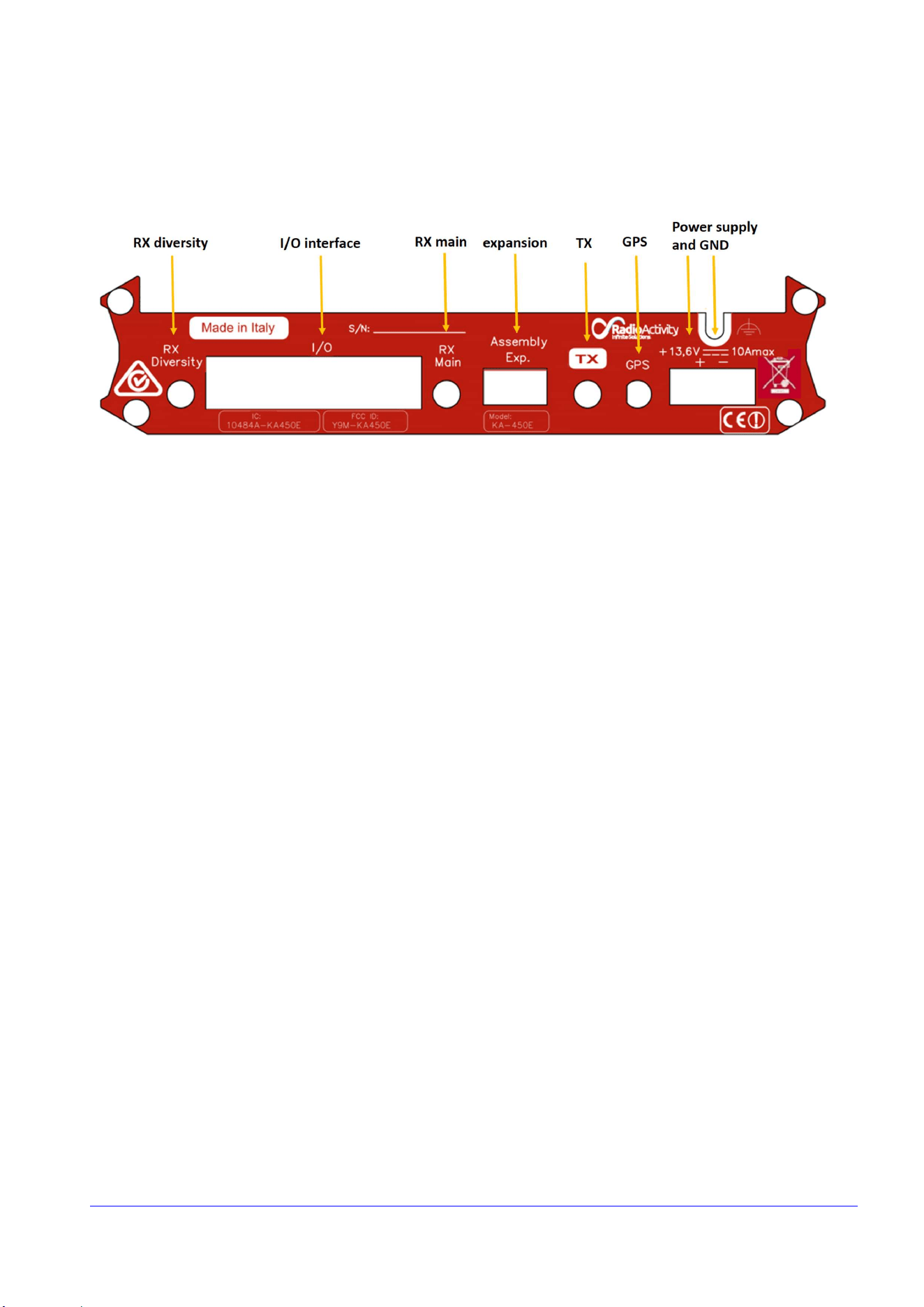
The following picture shows the rear panel of KAe.
The rear panel hosts the following connectors:
∞ RX diversity/main – female SMA-type connector. They are the input of the diversity/main channels
of the receiver. they are ground referred to discharge eventual static voltage, 50 Ohm of RF
impedance. Don’t apply continuous voltage to these inputs.
∞ TX – female SMA-type connector. It is the output of the transmitter. It is ground referred, 50 Ohm of
RF impedance. Don’t activate the transmitter without a proper load (50 Ohm) at this connector.
∞ GPS Antenna – female SMA-type connector (optional). A 5Vcc @ max 100mA is superimposed into
this connector to supply an external amplified GPS antenna. See the antenna details in the related
paragraph.
∞ I/O interface - 25 pin D-SUB. This connector holds a 12Vdc power supply, the balanced audio
interfaces, alarm I/O and some signals useful to interface KAe with external devices. For further
information about the use of these I/O see the related paragraph.
∞ Expansion connector - 6 pins. This connector holds the signals for GPS interfacing and for 1+1
assembly realizations. For further information about the use of these I/O see the related paragraph.
∞ Power supply – 2 pins. A 13,6Vdc @10A max should be applied to this connector. The polarity is
indicated on the panel.
Finally don’t forget to connect a ground cable to the GND Ø4MA nut to avoid lightning and rescue problems.
3.2.1 RX inputs specifications
KAe has got two RX inputs, one named “main” and the other named “diversity”. The contemporary use of
both receivers gives excellent performances over fading events. For further information, see the “ENB33 -
Soft diversity reception” document.
Both inputs have the following characteristics (typical):
Radio Activity S.r.l. 13 / 37
Nominal impedance 50 Ohm
Operating maximum input -10 dBm
Maximum input without permanent damages +10 dBm
Received signal band 0..5000 Hz
Blocking level (>1MHz far from RX frequency)
-
32 dBm
RSSI measurement range -130 to -60 dBm
Synthesis step 50 Hz
Connector type SMA
In duplex applications an external duplexer filter is requested. Using standard European duplex spacing, this
filter must attenuate at least 75dB between TX and RX to avoid noise and TX/RX instability during transitions.
For lower duplex spacing or when an external power amplifier is used, increase the attenuation to assure the
maximum levels indicated in the KAe manual.
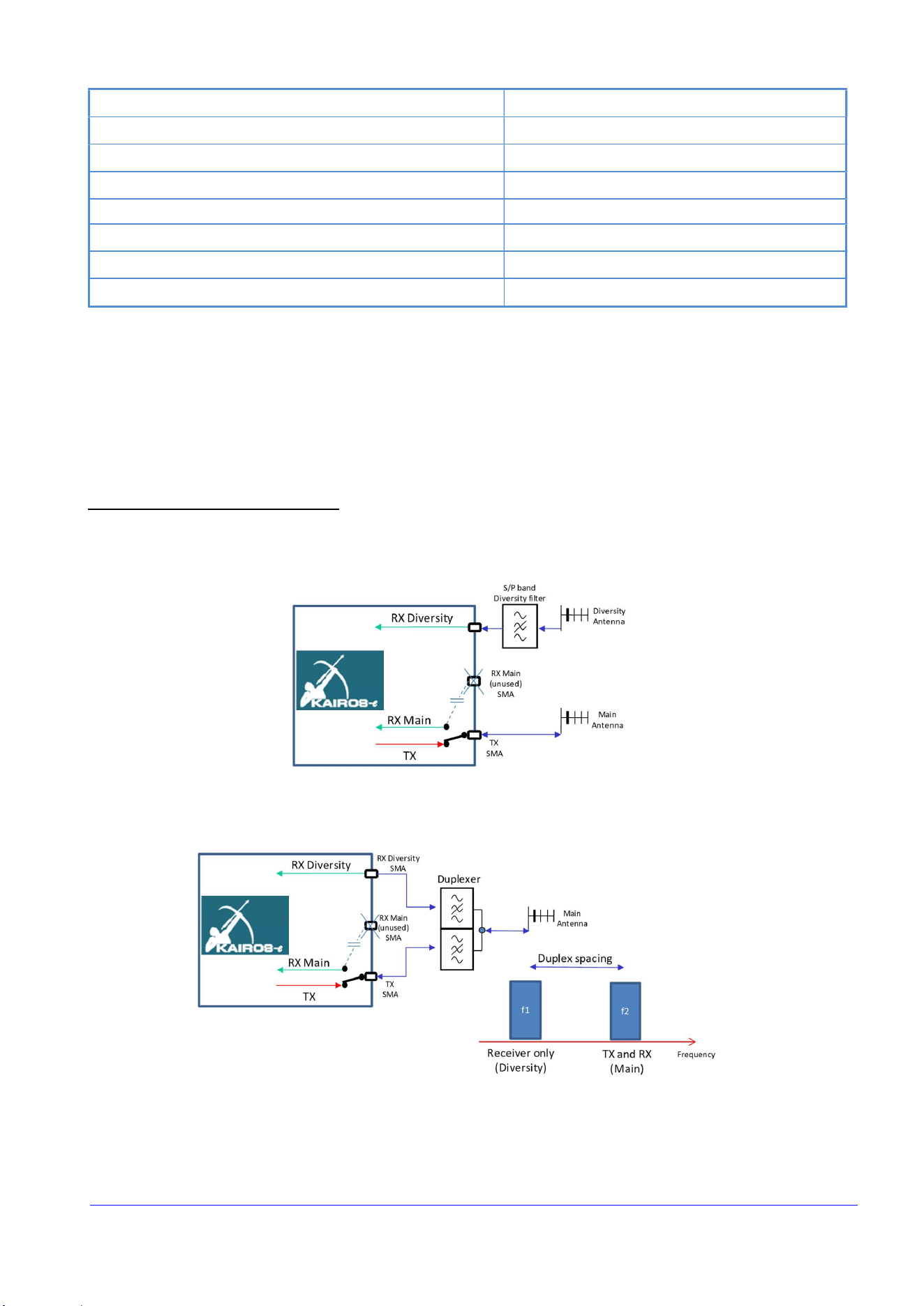
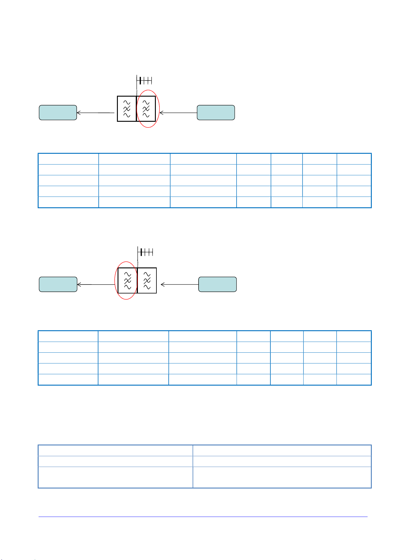
When KAe operates in simplex/half duplex mode, it is needed to mount the internal TX/RX RF switch as
indicated in the following figure. Note that this switch can’t be enabled/installed outside Factory. This feature
must be requested directly at order. In this case the TX connector assumes the role of Antenna connector
and the RX main is internally switched to the antenna when the TX isn’t active. The RX diversity in such
condition can be used regularly as diversity channel:
The internal isolation between the Diversity channel and the TX is around 80dB. This allow special realization
like a duplex/simplex station:
This realization allow to operate like a normal duplex station on f1=f_rx and f2=f_tx, and also in simplex/direct
mode at f2. The soft diversity feature, obviously, in this special application is lost. More details can be asked
to Factory.

Radio Activity S.r.l. 14 / 37
3.2.2 TX output specifications
Direct and reflected output powers are measured by a directional coupler. Power control circuit acts in a
closed loop and keeps constant the total power at MOSFET drain. If reflected power or mosfet temperature
exceeds protection threshold, regulation circuit will lower output power up to safe levels for transmitter.
Even though the TX implements many internal protections, it is recommended to connect a 50 Ohm load to
the TX port before to transmit.
An impedance mismatch at this port may produce unwanted intermodulation products or instability. So it is
recommended to verify accurately the branching system tuning before to place in service the equipment.
Play attention: a ports reversal between TX and RX or transmitting in a channel outside the branching tuning,
may destroy the RX and damage the TX!
Connector type
SMA
Nominal impedance
50 Ohm
Output power at the connector
1
to
5
0
W
RF final transistor protection to high temperature
85°C +/
-
5°C progressively reducing the RF power
Maximum power dissipation
75
W
Modulation bandwidth
0 .. 5000 Hz
Synthesis step
50 Hz
Transmitting duty cycle
Continued 100%
ROS protection
Min.10’ in short circuit as well as in open circuit
F
requency stability
0.1
p.p.m.
Max reverse input signal
-
20dBm to avoid intermodulation products
+30dBm no damage
Power amplifier works in C class and ensures a very high efficiency, lowering the needed power from supply
system and lowering the thermal dissipation inside the cabinet. When used at full power and high duty cycle
rate, the temperature of the equipment can increase some tens of °C over the ambient temperature. Inside
KAe a thermal sensor is hosted and it is directly connected to the internal microcontroller which enables the
command for air forced cooling fan of the cabinet if the temperature rises over 90°C. For heavy duty
applications it is recommended to assure appropriate ventilation and to protect users to accidentally touch
the equipment when hot.
The current flowing into final amplifier transistor is continuously monitored by microcontroller to verify the
correct functioning and to reveal an eventual efficiency degradation.
KAe is equipped with a harmonic filter to lower spurious emissions under required levels by existing
regulations.
In some applications, for example in multi carriers assembly or in sites with many transmitters, it is
recommended to use isolators/circulators to reduce possible intermodulation problems. Note that an
isolator assures only a limited isolation bandwidth: it can’t isolate a VHF TX from a UHF one! In similar cases
diplexers or cavity filters should be used.

Radio Activity S.r.l. 15 / 37
Unless the TX has got a built-in protection to a load mismatching, it is strongly recommended to achieve at
the TX output connector a VSWR (referenced to 50 Ohm) between 1 to 1.3.
3.2.3 GPS antenna
KAe is equipped with an embedded receiver for GPS service, with high precision Pulse Per Second (PPS)
output function in order to synchronize the station. Only an external active antenna is required.
The specifications of the external GPS antenna are:
Connector (RF + remote power supply)
SMA
Impedance
50 Ohm
Sensitivity Tracking
up to
-
159 dBm
Antenna gain
From 20 to 45
dB, depending on cable length, to obtain a total gain
between 12 dB and 26 dB (assumes a 3 dBic patch antenna).
A typical value of 25 dB is best in most cases.
Frequency band
GPS L1 1575.42 +/
-
10 MHz
;
Glonass G1 1589.0625 to 1605.375 MHz
Maximum Noise Figure
< 2.5 dB including pre
-
selector
DC Voltage
5Vcc @ max 100mA superimposed into the SMA RF connector
Out of Band Rejection
-
60 dB @ +/
-
50 MHz off center frequency
Lightening Protection
90 V, 20 kA, 8/20
-
S
Suggested model
GPS
-
TMG
-
SP
-
40N from PCTEL Broadband Technology
The PPS acquisition time is around 1 minute with good GPS signals (the frontal led “TX2” flashes red until the
PPS is ready). Once the PPS is acquired (the frontal led “TX2” flashes orange), another minute is request to
synchronize in time and frequency the equipment (than the frontal led “TX2” flashes green synchronously
with the arriving PPS).
KAe has the ability to automatic switch the synch source selecting the best available. The synch priority is
settable using the synch mask of the setup tool.
In multi equipment assembly like a multicarrier trunking application, it is possible to use only 1 GPS receiver
shearing the PPS signals to the other equipment via the 6pin connector placed in the back of the equipment
as shown in the following paragraphs.
3.2.3.1 In site GPS sharing
A special technique is implemented to allow also the use contemporary 2 or more GPS receivers for
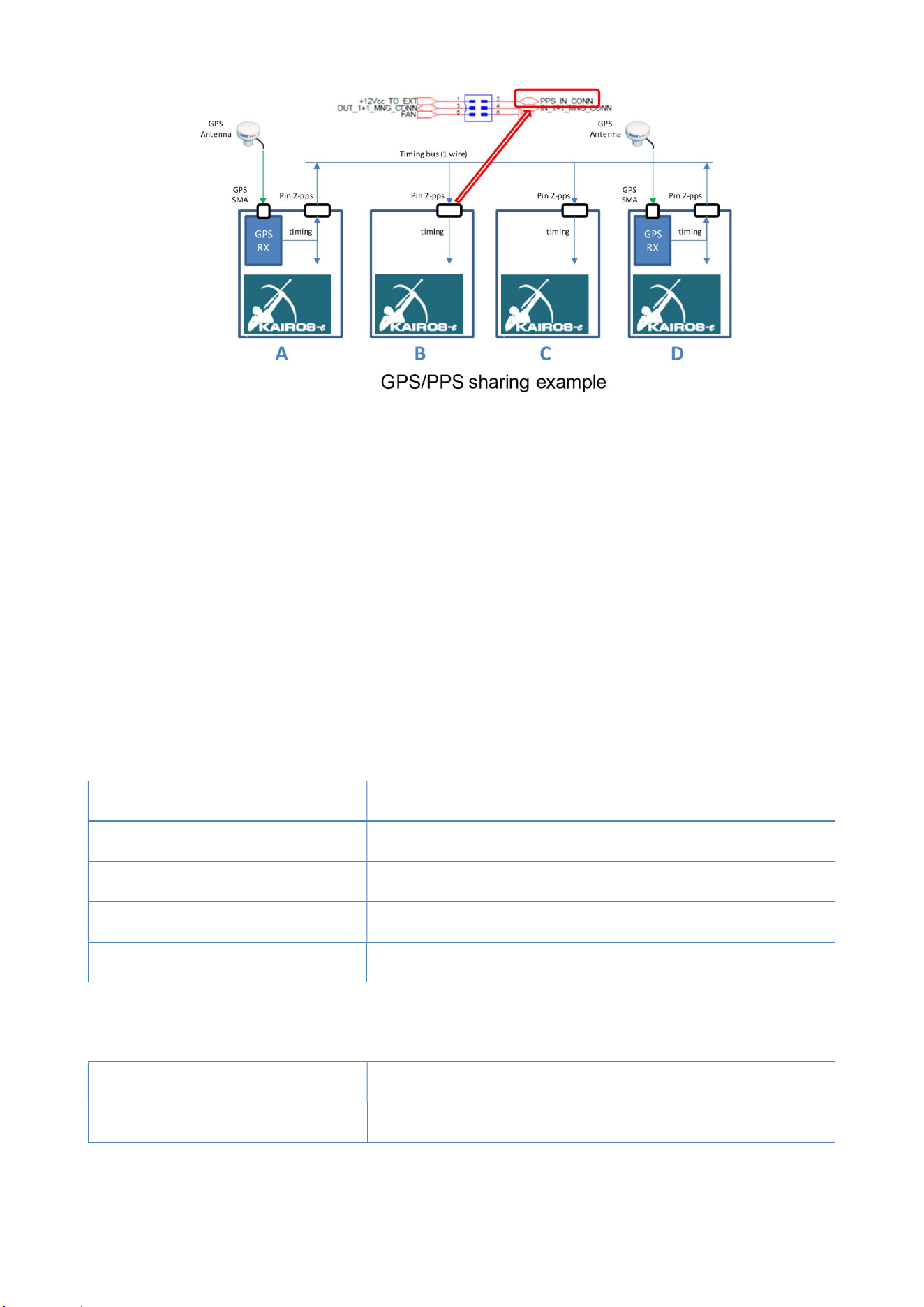
redundancy. The following figure explains how to share the PPS:
Radio Activity S.r.l. 16 / 37
In the example above, 4 KAe are assembled in the same cabinet. Two GPS antennas are used realizing a 1+1
redundancy in the synchronization source. The timing signal, sent out from both KAe equipped with the GPS
receiver, is used from all the other ones. A special protocol on the 1-wire timing bus allows automatic 1+1
redundancy management.
Since the timing bus (pin2-PPS and pin6-GND) carries a very high precision signal, this cable must be as short
as possible and placed away from high power RF antennas. Strong RF signals applies near this cable may
corrupts the synchronization integrity.
Since the frontal led “TX2” flashes green synchronously with the PPS signal, this led should flash in the same
instant on all the equipment connected together. This immediately gives a feedback about the right
connection in the rack.
This configuration requires the following setup in the equipment:
KAe “A” and “D”:
1
st
choice
Internal PPS (GPS/GLONASS)
2
nd
choice
External PPS (full)
3
rd
choice
Internal PTP (if this protocol is supported by the IP network)
4
th
choice
Internal ref (full)
PPS to rear plug
Internal ref
KAe “B” and “C”:
1
st
choice
External PPS (full)
2
nd
choice
Internal PTP (if this protocol is supported by the IP network)

Radio Activity S.r.l. 17 / 37
3
rd
choice
Internal ref (full)
4
th
choice
Internal ref (full)
PPS to rear
plug
Insulated
3.2.3.2 GPS sharing in RF linked stations
The main synchronization source in a RF linked simulcast network should be the GPS. In case of GPS failure,
the link transceiver is able to recover a time and frequency reference from the DMR signaling coming from
the Master station. This reference isn’t as precise as the GPS one but it is enough accurate to assure simulcast
operation with small degradations in the overlap area.
KAe has the ability to automatic switch the synch source selecting the best available. The GPS sharing
configuration is identical of the previous figure “GPS/PPS sharing example” where:
Slave
Master
A
Link transceiver
Link transceiver
B
Broadcast simulcast transceiver
Broadcast simulcast transceiver
C
-
Additional link receivers
D
Broadcast simulcast transceiver
Broadcast simulcast transceiver
The Broadcast transceiver can be equipped of the GPS receiver in case it is needed a redundancy in the GPS
signal (position “B” of the previous table).
Since the frontal led “TX2” flashes green synchronously with the PPS signal, this led should flash in the same
instant on all the equipments connected together. This immediately gives a feedback about the right
connection in the rack.
This configuration requires the following setup in the equipments:
KAe “A”:
Slave
Master
1
st
choice
Internal
PPS (GPS/GLONASS)
Internal PPS (GPS/GLONASS)
2
nd
choice
External PPS (full)
External PPS (full)
3
rd
choice
RF link (DMR)
Internal ref (full)
4
th
choice
Internal ref (full)
Internal ref (full)

Radio Activity S.r.l. 18 / 37
PPS to rear plug
Internal ref
Internal ref
KAe “B” and “C”:
Slave
Master
1
st
choice
External PPS (full)
External PPS (full)
2
nd
choice
Internal ref (full)
Internal ref (full)
3
rd
choice
Internal ref (full)
Internal ref (full)
4
th
choice
Internal ref (full)
Internal ref (full)
PPS to rear plug
Insulated
Insulated
KAe “D”:
Slave
Master
1
st
choice
Internal PPS (GPS/GLONASS)
Internal PPS (GPS/GLONASS)
2
nd
choice
External PPS (full)
External PPS (full)
3
rd
choice
Internal ref (full)
Internal ref (full)
4
th
choice
Internal ref (full)
Internal ref (full)
PPS to rear plug
Internal ref
Internal ref
3.2.4 Power supply
The equipment requires a 13.6Vdc nominal power supply with negative to ground. KAe switches off when a
polarity inversion or an out of range Vdc values are detected to its power supply input.
An internal circuit protects the equipment during fast voltage transients (e.g.: in mobile application) and
during accidental short circuit. It allows also a “soft start” limiting the in-rush current during the power-on
phase.
KAe implements also a non-restoring protection (internal fuse) to save the equipment from heavy transients
due to lightening. This protection acts absorbing the excess energy incoming from the power supply cable.
Note that, after a lightening event, this protection may short the power supply input. Therefore it is
recommended to insert a 20A fuse in the power supply cable near the power supply source (e.g.: a battery)
to avoid dangerous damage due to lightening event or to accidental short circuits along power supply cables.

Radio Activity S.r.l. 19 / 37
Internal power supply is not isolated. KAe must be supplied by an isolated power supply (from mains) with a
minimum isolation equal to the one of an IEC 61558-2-6 compliant safety transformer or equivalent.
The power supply input has the following characteristics:
Input Voltage
10.8
–
15.
4 Vdc, neg. ground, Nominal 13.6
V
Max ripple
30 mVpp
Polarity reversal protection
up to
-
70 V
Power supply protections
Electronic protection with automatic restore for
overvoltage
and
undervoltage events
Short
-
circuit protection
Electronic protection with automatic restore
Power supply connector
2 pole model Phoenix Contact
Power consumption @160MHz
13.6Vdc – typical values for both DMR
timeslot used
Power off : 1mA
GPS Receiver (without external antenna) : 30mA
LINUX & LAN + RX main
+ RX Diversity on : 450
mA
LINUX & LAN + RX mai
n + RX Diversity + TX @50W : 9
A
The DMR TIER 2 standard doesn’t require a continuous transmission from the repeater. Thus it’s easy to
calculate the battery’s autonomy as the following example:
Considering a simple KAe repeater operating at 50W for the 25% of time, the mean power requirement is:
I_mean=9*25% + 0.45*70% = 625 + 230 = 2.565mA
In case of a main power supply failure, a small 65Ah battery pack gives more than 1 days of full operation.
3.2.5 I/O ports
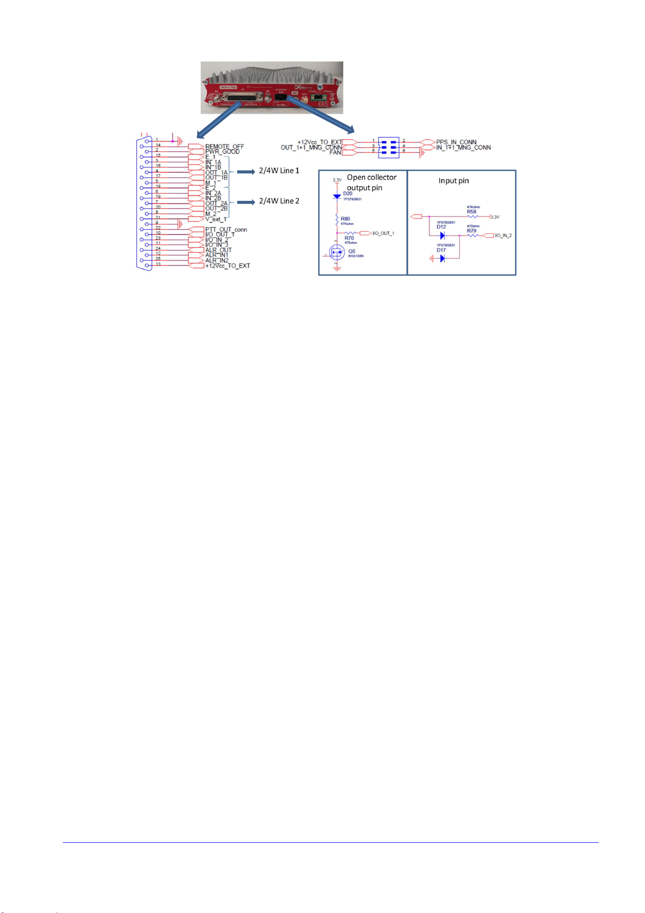
KAe provides some I/O ports fitted into the 25 pin D-SUB connector and the 6 pins connector placed in the
back. Some of these I/O are specialized (e.g.: PTT_out or ALRM_out) but can be re-defined for special
applications.
I/O contacts are not isolated from ground, they are referred to ground and pre-polarized by +3.3V. Due to
this configuration, for safety reason, they can be connected to very low voltage external circuits only.
Here following it is descripted the standard applications of these auxiliary pins.
Radio Activity S.r.l. 20 / 37
3.2.5.1 Digital I/O
The I/O output pins (PWR_GOOD, M_1, M_2, PTT_OUT_conn, I/O_OUT_1, ALR_OUT, FAN,
OUT_1+1_MNG_CONN) are open collector type able to switch up to 20mA/40Vdc. A 470 Ohm resistor limits
the maximum current and a 47K resistor refers the output to the internal 3.3V.
The I/O input pins (REMOTE_OFF, E_1, E_2, I/O_IN_2, I/O_IN_3, ALR_IN1, ALR_IN2, PPS_IN_CONN) are
internally pull-upped to the 3.3V. A pair of diodes protect the input from voltage below zero. This input switch
on closing it to GND.
The function of such pins are:
REMOTE_OFF : [IN] it is equivalent to push the on/off button in the front of the equipment. When KAe is in
on condition, closing this pin to GND for at least 3 seconds produces a switch off condition. When in off
condition, closing this pin to GND for at least 250 milliseconds produce a switch on. See the Power on/off
button description for further details using this pin.
PWR_GOOD : [OUT] it is closed to GND when the equipment is regularly switched on
E_1, E_2 : [IN] closing them to GND advise the equipment that a valid audio signal is incoming from the Line
(like a PTT signal)
M_1, M_2 : [OUT] they are closed to GND when a valid audio signal is sent to the Line (like a SQUELCH advise)
I/O_IN_2, I/O_IN_3 : [IN] general purpose inputs; they can be used in special applications that need to acquire
external status like: opening cabinet detection, opening site door, main power supply presence (with external
switch)
I/O_OUT_1 : [OUT] general purpose output; it can be used in special applications that need to set an external
device/relays
ALR_IN1, ALR_IN2 : [IN] alarm input; closing them to GND produces an alarm advise to the Supervisor Centre.
Each alarm can be configured via the setup tool; it is possible to define a DMR TXT message or a SNMP trap
for the 0 to 1 transition and for the 1 to 0. Typical application is the open site/cabinet event.

Radio Activity S.r.l. 21 / 37
ALR_OUT : [OUT] it is open from GND when the equipment detects an alarm condition. Power off is an alarm
condition.
FAN : [OUT] it is closed to GND when the temperature of the internal RF power amplifier rises above the
threshold (typ 65°C). It can be used to switch on cooling fans in a cabinet.
PTT_OUT_conn : [OUT] it is closed to GND when the transmitter goes on air. It is possible to insert a pre-time
to allow the right switching on time to an external RF power amplifier.
PPS_IN_CONN : [IN/OUT] this pin supports an external PPS signal or can share the internal PPS (from GPS
receiver or from the PTP or from other sourced synch). As described previously, a bus connection between
different co-located KAe realizes a multiple GPS reception with automatic backup. This pin can also be
configured to accept an external synchronous clock or an external pulse per second signal. Contact Factory
for further details.
IN/OUT_1+1_MNG_CONN : [IN/OUT] these pins support a simple protocol to allow two KAe to functioning
as 1+1 (main and spare) equipment.
V_ext_1 : [IN analog] not isolated inputs for voltage sensing (10KOhm / 0..24V referred to ground); the value
of this voltage can be seen via the remote control tool.
+12Vcc_TO_EXT : [OUT aux supply] this pin provides 13.2V, limited at 400mA, to supply a general purpose
external device
3.2.5.2 Audio I/O
KAe provides two 4 wires + E&M balanced interface for external audio consoles. These audio ports carry
analog, or DMR, or P25 communications.
The inputs are IN_1A/IN_1B for the Audio Line 1 and IN_2A/IN_2B for the Audio Line 2 (Z_in = 20KOhm
differential / 10KOhm single ended). The outputs are OUT_1A/ OUT_1B for the Audio Line 1 and OUT_2A/
OUT_2B for the Audio Line 2. These two outputs have different impedance:
∞ Audio Line 1 Z_out = 600 Ohm differential / 300 Ohm single ended.
∞ Audio Line 2 Z_out = 150 Ohm differential / 75 Ohm single ended.
These IN/OUT ports are balanced and ground referred (NOT FLOAT! don’t apply to these pins more than
20Vdc). For long line use, it is recommended to insert an external 1:1 transformer in order to isolate the port
from static voltage difference that can be arise between the line ends.
They can be used as balanced (suggested method) or as single ended using only one of the IN/OUT pin. The
nominal level of the audio signal in/out is -10dBm and can be regulated via setup tool between -20 and 0
dBm (-14 to -6dBm in single ended).
These Audio ports, in conjunction with the E_1, E_2, M_1, M_2 I/O signals described before, realize a double
4Wire+E&M interface.
In analog communications the standard settings of these ports are:

Radio Activity S.r.l. 22 / 37
∞ Audio Line 1 is the audio port for Console; it is a PM (phase modulated = the incoming audio is
emphasized) audio port
∞ Audio Line 2 is the audio port for External modem (e.g.: paging interface); this port is a FM (frequency
modulated = the incoming audio is “flat”) audio port
In digital communication, these ports have the following roles:
∞ Audio Line 1: this port is connected to the DMR timeslot 1.
∞ Audio Line 2: this port is connected to the DMR timeslot 2, or P25.
The audio line settings (levels, filters, …) are configurable with the setup tool.
4 Installation and maintenance
4.1 Improper use
It is recommended to install the equipment in closed cabinet, to allow only authorized people to access to
them, in order to avoid handling or improper use of equipment and to avoid accidental contact with hot
surfaces.
4.2 Thermal dissipation
The repeater may be installed in any location suitable for electronic communications equipment, provided
that the environmental conditions do not exceed the equipment specifications for temperature and
humidity. Humidity conditions should not exceed 95% relative humidity at 50 °C (122 °F).
The temperature, measured in close proximity to the equipment, should not exceed -30 °C (-22 °F) to +60 °C
(+140 °F). Therefore, if the equipment is mounted in a cabinet, the temperature within the cabinet should be
maintained within this range.
When planning the installation, observe the following ventilation guidelines:
∞ Outlet cabinet containing the equipment should be designed to ensure a good internal air flux for
heating dissipation. A free slot of at least 1TU is recommended between two adjacent equipment.
∞ If several equipment are installed in a single cabinet, ensure adequate cooling/ventilation to each
equipment. The cabinets should be equipped with ventilation slots or openings in the front (for air
entry) and back or side panels (for air to exit). The cabinet must have a least 15 cm (6 inches) of open
space between the air vents and any wall or other objects.
∞ In case RF transmitter is set for its maximum power, it is active with a duty-cycle near to 100% and
ambient temperature could be above 40°C, a larger respect area must be considered around the rack
and an air forced cooling system should be eventually designed (“FAN” contact of the equipment can
be used to switch on and off an external cooling system). The transmitter is protected against over-
temperature: if the RF mosfet temperature arises over 90°C, the microprocessor will automatically

Radio Activity S.r.l. 23 / 37
decrease the generated RF power in order to make the amplifier work in safety conditions. The
nominal RF power will be restored as soon as the mosfet temperature will decrease below 60°C.
4.3 Power supply system
Internal power supply voltage is nominally set to 13.6V dc from battery, with negative pole connected to
ground, and it is protected against polarity inversion, over-voltage, under-voltage, short-circuits.
It is recommended to use power supply sources with low impedance output stage to make the hot swap
controller of PSU properly work. For example, if the power supply line is very long a capacitor should be
added in parallel in order to reduce the resulting output impedance.
The power supply input has a built-in RF filter that reduce the inout noise. A ferrite bead should be inserted
in the power supply cable for very low noise applications or for cable length that exceeds 3 meters.
Note: use cable with adequate section and don’t insert inductive devices because they could produce extra-
voltage that activate internal electronic protections giving on/off instability.
Power supply cable dimensions must be calculated for a maximum current absorption of 10A @13.6V DC, in
order to avoid significant voltage drop, especially after fast transient. They must be protected by a fuse or a
short circuit protection system which should be placed as near as possible to each power supply source
(AC/DC and battery).
It is also recommended to connect a good ground reference to the rack, to its metal components and to KAe
by using the screw on the rear side of the equipment.
4.4 Antenna
Antenna discharger are recommended to prevent damages due to eventual atmospheric discharges. These
devices should be placed on antenna connection cable, just before equipment installation shelter, and they
must be connected to an good ground reference.
Attention must be paid also to connect the eventual diversity receiver to the radiant system: the input of this
receiver is directly connected to a SMA connector on the back side of the rack, without any filter. The
corresponding antenna must be placed far enough from the transmitting antenna in order to avoid receiver
desensitization and to get the correct isolation. To avoid any problem, it is recommended to insert a notch
or a pass-band cavity to protect the receiver.
If an external branching is connected to the equipment, it must be designed to ensure minimum reflected
power at the TX port (VSWR referenced to 50 Ohm less than 1.3) and the needed isolations between
transmitter and receivers. See the branching paragraph in the engineering specification appendix.
4.4.1 Maximum permitted antenna gain for mobile usage
Please note that there is an ERP limit in both SRSP-500 specifications by IC and in FCC Part 90 I, equal to 30
Watts (that is 44.8dBm) ERP, for mobile equipment. As KAe can generate a maximum RF power of 50W
(47dBm), for mobile usage of KAe transmitted power must be reduced to 30W.

Radio Activity S.r.l. 24 / 37
4.4.2 Maximum permitted antenna gain for fixed usage
Please note that there is an ERP limit in both SRSP-500 specifications by IC and in FCC Part 90 I, equal to 125
Watts (that is 51dBm) ERP, for fixed equipment. As KAe can generate a maximum RF power of 47.3 dBm, the
margin between maximum radiated ERP power and transmitted power is 3.7dB (corresponding to 5.85dBi).
The consequence is that for fixed usage of KAe, the maximum permitted antenna gain (by IC and FCC) is
5.85dBi.
4.5 AF interface
These IN/OUT ports are balanced and ground referred (NOT FLOAT! don’t apply to these pins more than
20Vdc). For long line use, it is recommended to insert an external 1:1 transformer in order to isolate the port
from static voltage difference that can be arise between the line ends.
4.6 Manual settings
No manual settings are required for KAe repeaters.
4.7 Self-test process
During self-test process internal parameters of modulator and demodulators are tuned by generating a signal
through the synthesizer of the transmitter, by automatically connecting its output to the input of the receiver
and by analyzing the received signal. If a strong signal is received by the external antenna during self-test, it
is possible that the process ends with errors (a corresponding “warning” alarm will be displayed on both
frontal led and monitor of PC for remote control). In this case the DSP will load from flash memory the
previously saved parameters without any problem for the transceiver.
4.8 PPS signal
For applications in simulcast networks where the source of synchronization is the PPS signal by GPS, if this
signal is missing, the radio coverage of the areas which are reached by several repeaters with the same field
strength, is not ensured. Attention must be paid in choosing and placing the GPS antenna.
The GPS quality and the effective antenna efficiency can be checked connecting to the equipment through
the setup tool.
4.9 On site check list
Once the equipment is placed in the transmission site it is a good practice to measure some parameters to
be sure that the site is ready and for future reference.
The main measures should be:
∞ Power supply voltage; it should be 13,6Vdc measured at the KAe input. The internal monitor,
accessible via the setup tool, should indicate around 13,6V +/- 300mV in standby; this standby value
should not decrease for more than -600mV in TX @10W and -800mV in TX @25W (values valid for

Radio Activity S.r.l. 25 / 37
VHF model). Be sure that, at the nominal RF power, the power supply be at least 12Vdc. Remember
that noisy power supply may produce unwanted disturbs both in TX and in RX.
∞ TX power to the antenna; keeping in account the branching loss, it should be within +/-1 dB (+/-2W
@10W) respect to the nominal power set.
∞ Antenna and branching system; verify the reflected power at the TX output and at the branching
output to the antenna. Unless the TX has got a built-in protection to a load mismatching, it is strongly
recommended to achieve at the TX output connector a VSWR (referenced to 50 Ohm) between 1 to
1.3. In presence of higher value of VSWR, the system performance will be degraded. In this case a
variety of symptoms might appear, like:
1. The reflected power might change varying the length of cable between transmitter and the
branching system.
2. The transmitter might generate spurious radiations.
3. The transmitter might increase its floor noise; this can produce de-sensitivity on the receiver
path.
4. The transmitter output power might become erratic, either too high or too low as measured on
a wattmeter.
In case of a poor branching system, the use of a ferrite isolator at the output of the transmitter should
solve the reflected power problem.
∞ RX sensitivity; since KAe is a digital transceiver, the sensitivity should be measured in digital. Anyway,
considering that the digital demodulation is only a SW algorithm, it is enough to measure the
sensitivity in analog. The sensitivity should be measured on both channels, Main and Diversity, with
the branching filters. The S/N should be better than 20dB with a RF field of -113dBm @12.5KHz of
channel spacing.
∞ RX de-sensitivity; this measure verifies the RF pollution that influences the antenna. Connect the RX
input to the antenna inserting a directional coupler. The sensitivity measured with the antenna and
substituting it with a dummy load should differ for few dB (typical value: 2-6 dB @160MHz, 1-3dB
@450MHz). If the measured value is not satisfactory, you can try to insert a band pass cavity filter.
∞ RX de-sensitivity when the TX is on; this measure verify the correct isolation of the TX/RX filter
system. Connect the antenna input to a duplex test set analyzer. The sensitivity with the TX on
respect when off, should differ for less than 3 dB (this value may vary with the TX/RX band
separation). If the measured value is not satisfactory, the TX/RX isolation of the branching filter
should be increased; the problem may be also in the noise of the power supply when the equipment
is in TX.
∞ Verify the IP network functionality (if the equipment is a part of a network); if the Master station is
present, a KAe slave should register itself to the master within 1 minute. The led “NETWORK” in the
frontal panel should blink green. Verify all the signal path: a signal received locally must arrive to the
Master (see its voter mask), must be selected in the master and must be transmitted locally. Be sure
that the signal re-transmitted is effectively the signal coming from the Master and not a local copy.

Radio Activity S.r.l. 26 / 37
∞ At the end remember to save on your PC all configuration parameters of the base station; these
parameters can be very useful to clone a substituting unit in case of fail.
4.10 IP discover
When KAe is placed in field or comes back from a site, its IP address could be unknown. A simple way to
discover the IP is to connect to KAe through its standard alias IP address, which is 172.33.15.140.
Writing that IP address on web browser, it is possible to read the programmed IP address. Please, make sure
that only one device can be reached, when using the alias IP.
4.11 Preventive Maintenance
KAe does not require a scheduled preventive maintenance program; however, periodic visual inspection and
cleaning is recommended. Check that the external surfaces of the radio are clean, and that all external
controls and switches are functional. It is not recommended to inspect the interior electronic circuitry.

Radio Activity S.r.l. 27 / 37
5 Parameters configuration and Remote Control
Working parameter of the station are completely programmable through a web browser and a PC
connection. The visible (and programmable) parameters set is very wide and extends from radio channel
setting to tuning voltage measure of each local oscillator. No specific SW is needed for connection.
Remote diagnostic of radio stations from PC can be performed through the Ethernet interface of the station.
Each operation can be remotely performed, exactly the same as in local connection, including FW down-
loading, configuration Down-loading and up-loading, station check, parameters changing.
If defined “self-alarming” events happen, device is able to generate spontaneous alarms to transmit by SNMP
traps, digital radio messages, status messages to remote control PC.
For further details about remote control software, refer to proper documentation (KAe operational manuals).
5.1 Gateway for digital console
KAe embeds a RTP interface for connecting to PC-based digital dispatching systems and an extended SIP
agent for managing connection to advanced digital consoles, VoIP systems and telephone devices, which
work with standard protocols like SIP, AIS for DMR, DFSI for P25, and so on.
KAe acts as Gateway for interfacing both analog and digital radio communications with several external
networks (vocoder functionality is embedded for transcoding digital voice to analog and vice-versa). It allows
radio users to easily communicate and interoperate with:
∞ External telephone applications like VoIP systems (SIP IPBX, SIP Handphones, Softphones, Open Source
SIP platforms).
∞ Dispatching systems and control room applications like analog 4-wire + E&M consoles, RTP based
consoles, SIP (and other similar protocols derived from SIP) based dispatching systems for control room
applications, to connect a Base Station (or a radio network) to a local operator desk.
∞ Other users under different radio networks/repeater (Wide Area Mobility).
The digital Gateway Agent translates Voice (full duplex audio streams from/to digital coded audio to G.711
-law or a-law) and Data streams, along with the associated signaling (for example SIP RequestsDMR or
DTMFDMR) to provide the interconnection between these communication systems.
This audio can be easily managed using standard audio program and application on a PC. Radio Activity will
provide the protocol descriptions to allow his partners to develop their own applications.
See the SIP/RTP Gateway document for more details.

Radio Activity S.r.l. 28 / 37
6 Engineering specifications
6.1 KAe main specifications
KAe
Mechanic
Single module
Weight
1,5
k
g
Operative System
LINUX
Internal Memory (RAM/FLASH)
1Gbyte (256Mx32)/8Gbyte
Diversity RX
Always present
Power supply
13,6Vdc (10.8 to 15.4V)
RX power consumption
<6W
TX Power
50W (30W at 900MHz band)
Simulcast
Yes (as option)
Channelization
25/20/12,5/6,25 k
Hz
Bands
72
-
76
; 136
-
174
EU / 150
-
174 FCC / 138
-
174 ISED
;
39-50; 406.1-470; 450-512 FCC/470 ISED; 806-941 MHz
Multiprotocol digital/analog
Yes (as option)
DMR TIER 3
Yes (as option)
P25 phase 1 conventional
Yes (as option)
Operation
duplex / half duplex / simplex
Vehicular/mobile repeater
Yes
Built in audio lines
2
User I/O
4 not insulated
Internal GPS Receiver
yes
SIP/RTP Gateway
Internal
1+1 (Main/Spare) operation
Yes (as option)
USB Port
Yes

Radio Activity S.r.l. 29 / 37
6.2 Radio frequency
6.2.1 Transmitter
Output power
at the connector
1 .. 50 W
Connector
SMA
RF final
transistor protection to high temperature
90°
C +/
-
5°C progressively reducing the RF power
Available modulation
FM,
PM, GFSK, 4FSK
, 2DFSK
Modulation bandwidth
0
.. 50
00 Hz
Synthesis step
50
Hz
Transmitting duty
cycle
Continued
100%
ROS protection
Min.
10’ in short circuit as well as in
open circuit
Adjacent channel
noise
-
75
dBc @25k
Hz
/
-
65 dBc @12.5k
Hz
FM distortion
<
1.5 %
Noise
-
56
dBp @25k
Hz
/
-
47
dBp @12.5k
Hz
Frequency stability
0.1
p.p.m.
Max reverse input signal
-
20dBm
to avoid intermodulation products
+30dBm no damage
Emission Designator (ITU)
4FSK
Digital Modulation
(DMR)
12.5 kHz Data Only: 7K60FXD
12.5 kHz Data and Voice: 7K60FXE
C4FM Digital Modulation (P25)
12.5 kHz Data Only: 8K10F1D
12.5 kHz Data and Voice: 8K10F1E
FM Modulation
12.5 kHz: 11K0F3E (voice); 11K0G3E (data)
25 kHz: 16K0F3E (voice); 16K0G3E (data)
20 kHz: 14K0F3E (voice); 14K0G3E (data)
6.2.2 Receiver
Maximum sensitivity
-
116
dBm @20 dBp SINAD
-118dBm @5% BER without diversity
-121dBm @5% BER with diversity
Operating maximum
input
-
10
dBm
Maximum input
without permanent damages
+10
dBm
Reception mode
Vector
I &
Q
Received signal
band
0..5000
Hz
Synthesis step
50
Hz
Co
-
channel protection
8
dB @25 KHz
/
12 dB @12.5k
Hz
Adjacent channel
selectivity
73
dB @25 k
Hz
/
6
3
dB @12.5 k
Hz
Blocking protection
80
dB
Intermodulation protection
75
dB

Radio Activity S.r.l. 30 / 37
Intercept 3°
order IP3in
+15
dBm
Distortion
<2
%
@1k
Hz
Noise
-
53
dBp @25
k
Hz
/
-
47 dBp @12.5 k
Hz
Frequency stability
0.1
p.p.m.
6.3 IP interfacing
6.3.1 LAN protocols
6.3.2 Ports and connectors
UTP LAN
Port
Ethernet
10
/100
/1000
(auto MDI/MDI
-
X) on an RJ45 socket
USB Port
A
type
Protocols for voice packets
Proprietary
among base stations
:
UDP/IP (ipv4), selectable from multicast/unicast/broadcast
(from master to Slave), with DSCP set to “EF” (
Telephony
service class), according to RFC 4594
Between gateway and dispatching applications:
RTP (Real Time Protocol) according to RFC 3550
Protocols for BS “internal” network control
UDP/
IP (ipv4), unicast and multicast, with DSCP set to
“CS6” (Network Control service class), according to RFC
4594
Protocols for remote control, setup and
surveillance
UDP/
IP and TCP/IP (ipv4) unicast and broadcast with DSCP
set to “AF13” (High-Throughput Data service class),
according to RFC 4594
PTP Precision Time Protocol over IP
Selectable
as compliant with
IEEE 1588 standard
or unicast
proprietary.
Audio format
Analog:
64 kb/s
–
8 bit x 8 KHz selectable linear or mu
-
law
coded
DMR: AMBE II+
TM
(Advanced Multi-Band Excitation)
P25: IMBE (AMBE full rate)
RTP 64 kb/s – 8 bit x 8 kHz selectable A or mu-law coded
Messaging for PC/SIP application
variable
length
RTP for text messaging according to RFC
4103

Radio Activity S.r.l. 31 / 37
6.3.3 LAN requirements
6.3.4 Codec VoIP
Uncoded audio
source
64
kbps
–
8bitx8k
Hz
Net bit
-
rate
(1CH)
2450
bps
FEC Coded
bit
-
rate (1CH)
3600
bps
Audio frame
block
20ms
Coder algorithm
AMBE
II+
TM
(Advanced
Multi
-
Band Excitation
)
6.3.5 SNMP protocol
Version compatibility
2.0
Maximum number
of managed server ports
8
Traps description
On
MIB file included in the standard SW package
Jitter (deviation of averaged packet time delay)
The
Base Station is able to compensate Jitter delay up to
200 ms. The total delay averaged + jitter must not exceeds
500ms (each way)
Maximum delay
The
Base Station is able to compensa
te round trip delay
less then 1080ms (jitters included)
Packet loss
<
0.1 %
Minimum bandwidth (network signaling and
remote control polling inclusive)
SLAVE:
70 kb/s in analog to/from Master
24 kb/s in DMR to/from Master (both timeslots)
MASTER
to serve
N
SLAVES or RA
-
TI
-
XX (both timeslots):
Using multicast (preferred method) or broadcast:
70 kb/s in analog to Slaves, 70 kb/s x N from Slaves
24 kb/s in DMR to Slaves, 24 kb/s x N from Slaves
Using unicast:
70 kb/s x N in analog to Slaves, 70 kb/s x N from Slaves
24 kb/s x N in DMR to Slaves, 24 kb/s x N from Slaves

Radio Activity S.r.l. 32 / 37
6.4 GPS/GLONASS antenna
6.4.1 GPS/GLONASS antenna requirements
Connector (RF
+ remote power supply)
SMA
Impedance
50
Ohm
Sensitivity Tracking
up
to
-
159 dBm
Antenna gain
From
20 to 45 dB, depending on cable length, to obtain a
total gain between 12 dB and 26 dB (assumes a 3 dBic
patch antenna).
A typical value of 25 dB is best in most cases.
Frequency band
GPS
L1
1575.42 +/
-
10 MHz
Maximum Noise
Figure
<
2.5 dB
including pre
-
selector
DC Voltage
5Vcc
@
max 100mA
superimposed into the SMA RF
connector
Out of
Band Rejection
-
60
dB @ +/
-
50 MHz off
center frequency
Lightening Protection
90
V, 20 kA, 8/20
-
S
Note: It is necessary only 1 antenna per site independently from the number of base stations. The pps
signal received from one base station can be shared to the other ones in the same cabinet via the 6-pins
bus on the back of KAe.
6.5 Frequency bands
Model
Frequency
band
KA
-
900
E
UHF
–
HH
=> 806
-
9
41
MHz
KA
-
500
E
UHF
–
H => 450
-
512 FCC / 470 ISED
MHz
KA
-
450
E
UHF
–
M => 40
6.1
-
470 MHz
KA
-
040E
LOW =
> 3
9
-
50
MHz
KA
-
160
E
VHF
–
H =>
136
-
174 EU / 150
-
174 FCC / 138
-
174 ISED
MHz
KA
-
080
E
VHF
–
L =>
72
-
76
MHz
KA
-
040
E
*
VHF
–
LL => 30
-
40 MHz
* please, ask to Factory the availability
Radio Activity S.r.l. 33 / 37
6.6 Branching requirements
6.6.1 TX to antenna duplex isolation requirements @10W TX RF power
Band
+/
-
40MHz
+/
-
9MHz
+/
-
4.5MHz
+/
-
3MHz
+/
-
1.5MHz
+/
-
0.8MHz
UHF
–
HH
75dB
UHF
–
H/L
75dB
76dB
VHF
–
H
75dB
75dB
76dB
78dB
81dB
85dB
VHF
–
L
75dB
75dB
75dB
75dB
78dB
81dB
6.6.2 Suggested RX max input limits on unwanted signals
Band
+/
-
1MHz
+/
-
500k
Hz
+/
-
100k
Hz
+/
-
50k
Hz
+/
-
25k
Hz
+/
-
12.5k
Hz
UHF
–
HH
-
32dBm
-
43dBm
-
45dBm
-
47dBm
-
49dBm
-
58dBm
UHF
–
H/L
-
32dBm
-
41dBm
-
43dBm
-
44dBm
-
48dBm
-
56dBm
VHF
–
H
-
32dBm
-
40dBm
-
42dBm
-
43dBm
-
47dBm
-
54dBm
VHF
–
L
-
32dBm
-
36dBm
-
38dBm
-
40dBm
-
43dBm
-
50dBm
6.7 Other specifications
6.7.1 Environmental parameters
Operating Temperature
-
30
÷ +60 °C
Storage Temperature
-
40
÷ +70 °C
Relative Humidity
(operating and storage)
Max 80% not condensed
TX
RX main
TX
RX main

Radio Activity S.r.l. 34 / 37
6.7.2 Power supply
Input Voltage
10.8
–
15.
4
Vcc, neg. ground, Nominal 13.
6
V
Max ripple
30
mVpp
Polarity reversal protection
up
to
-
70 V
Power supply protections
Electronic
protection with automatic restore for
overvoltage and undervoltage events
Short-circuit protection
Electronic
protection with automatic restore
Power supply connector
2
pole model Phoenix Contact
Ground connections
A
Ø
4
MA nut on the rear side of the base station
The central contact on the power supply connector
Power consumption
TX:
120 W @50
W RF
RX: 5 W (with both RX main and diversity enabled)
6.7.3 Mechanical characteristics
Dimensions (including connectors)
48
x 197x 220 mm
19” Rack mount assembly for up to 2 transceivers
87
(2TU) x 426 x 220 mm
19” Rack mount assembly for up to 6 transceivers
215
(5TU) x 426 x 220 mm
Weight (1 transceiver)
1.5
k
g
6.7.4 Audio balanced interfaces
Interface type
2x4+E&
M
balanced line
s
Line isolation
20
V
Used audio
bandwidth
300÷
3400 Hz
Input/output Impedance
Line1
=>
600 Ohm differential / 300 Ohm single ended
Line2 => 150 Ohm differential / 75 Ohm single ended
Side tone
reflection
<
-
20 dB
Output nominal
level
-
30
.. 0 dBm
Input nominal
level
-
30
.. 0 dBm
Level adjust
software
by 0.1dB step
7 REGULATIONS COMPLIANCE
KAe is compliant with the existing regulations, in particular:

Radio Activity S.r.l. 35 / 37
∞ EN 300 086-2: Technical characteristics and test conditions for radio equipment for analogue speech.
∞ EN 300 113-2: Technical characteristics and test conditions for non speech radio equipment for the
transmission of data.
∞ EN 62368-1: Audio/video, information and communication technology equipment - Safety
requirements
∞ EN 301489-1/5: Electromagnetic compatibility
∞ FCC: Part 90; subpart I
∞ P25 CAP
∞ ISED: RSS119
∞ ETSI TS 102361 (part 1;2;3): Electromagnetic compatibility and Radio spectrum Matters (ERM);
Digital Mobile Radio (DMR) Systems. The equipment is able to manage OSI stack layers 1–2–3 of the
DMR protocol, offering an active interaction with mobile terminals.
∞ European Directive 2014/53/EU (RED)
The product is conformed to the Directive 2002/95/CE - RoHs (“ro-has”). It doesn’t contain concentrations
exceeding the permitted limits for the following substances:
∞ Lead (Pb)
∞ Mercury (Hg)
∞ Cadmium (Cd)
∞ Hexavalent chromium (Cr (VI))
∞ Polybrominated biphenyls (PBB)
∞ Polybrominated diphenyl ethers (PBDEs)
The use of this equipment may be subject to the specific authorization by the national authority responsible
for spectrum management, and it should operate under the local government laws.
Errore. Il segnalibro non è definito.
Please refer to the document “Declaration of conformity KA-xxx.doc” (where “xxx” is the specific model,
which is referred to) for signed certification of compliance of the KAe to normatives.
7.1 Notice for EC users
KAIROS products have been certified according to the essential requirements stated by Directive
2014/53/EU. It satisfies the following standards:
- EN 62368-1:2014 and EN 50385:2002
- EN 301489-1 V2.1.1 and EN 301489-5 V2.2.0
- EN 300113 V2.2.1 and EN 300086 V2.1.2
Please make sure to have the needed permissions by local Authorities to work on the desired frequencies:
some frequency ranges of the full usable band may be not permitted in some Countries for any application.

Radio Activity S.r.l. 36 / 37
The following table shows the list of EU Countries where the equipment is intended to be used:
AT
BE
BG CH
CY
CZ
DE
DK
EE
EL
ES
FI FR HR
HU
IE IS IT LI LT
LU
LV
MT NL
NO
PL
PT
RO
SE
SI
SK
TR
UK(NI)
7.2 Notice for US users
The equipment is compliant with the FCC Part 90 and 22 Radio standards and with the CFR 47 Part 15
Subpart B EMC standard.
Changes or modifications not expressly approved by Radio Activity may void the FCC authorization to operate
the equipment.
This equipment has been tested and found to comply with the limits for a Class B digital device, pursuant to
part 15 of the FCC Rules. These limits are designed to provide reasonable protection against harmful
interference in a residential installation. This equipment generates, uses and can radiate radio frequency
energy and, if not installed and used in accordance with the instructions, may cause harmful interference to
radio communications. However, there is no guarantee that interference will not occur in a particular
installation. If this equipment does cause harmful interference to radio or television reception, which can be
determined by turning the equipment off and on, the user is encouraged to try to correct the interference
by one or more of the following measures:
—Reorient or relocate the receiving antenna.
—Increase the separation between the equipment and receiver.
—Connect the equipment into an outlet on a circuit different from that to which the receiver is connected.
—Consult the dealer or an experienced radio/TV technician for help.
7.3 Notice for Canadian users
This radio transmitter has been approved by Innovation, Science and Economic Development Canada to
operate with the antenna types reported in the section 2.1 RF Exposure Compliance, with the maximum
permissible gain indicated. Antenna types not included in this list that have a gain greater than the maximum
gain indicated for any type listed are strictly prohibited for use with this device.
Le présent émetteur radio a été approuvé par Innovation, Sciences et Développement économique Canada
pour fonctionner avec les types d'antenne énumérés dans la section 2.1 RF Exposure Compliance et ayant un
gain admissible maximal. Les types d'antenne non inclus dans cette liste, et dont le gain est supérieur au gain
maximal indiqué pour tout type figurant sur la liste, sont strictement interdits pour l'exploitation de
l'émetteur.

Radio Activity S.r.l. 37 / 37
This device complies with Health Canada's Safety Code 6. The installer of this device should ensure that RF
radiation is not emitted in excess of the Health Canada's requirement.
Cet appareil est conforme avec Santé Canada Code de sécurité 6. Le programme d'installation de cet appareil
doit s'assurer que les rayonnements RF n'est pas émis au-delà de I'exigence de Santé Canada.
ICES-003 Class B Notice - Avis NMB-003 Classe B:
This Class B digital device complies with Canadian ICES-003.
Cet appareil numerique classe B est conforme à la norme NMB-003 du Canada.
CAN ICES-3(B) / NMB-3(B)

