

Owner´s Manual
Mode d´emploi
Power Amplifier
Amplificateur de Puissance
Français
English

2
Thank you and congratulations on your purchase of this Yamaha product.
¡
You can enjoy the high-quality stereo sound of this power amplier at home.
¡
This Owner’s Manual describes the unit’s features and connection procedures.
¡
To use the product properly and safely, we suggest that you read this manual and Safety Brochure
(separate booklet) thoroughly.
Keep the manual in a safe, accessible place for future reference.
You can download a PDF version of this manual from the following Yamaha website.
https://download.yamaha.com/
Features
¡
Full oating and balanced transmission from input to output
¡
High-rigidity lever selectors
¡
Stable mechanical grounding construction dramatically lessens the impact of external vibrations
¡
Left-right symmetrical design
¡
Large power supply with four separate circuits, and large capacitors of 33000 μF
Í
4
¡
Newly-designed brass spiked feet
¡
Powerful 400 W/8Ω output driven in monaural
About this manual
¡
The illustrations as shown in this manual are for instructional purposes only.
¡
The company names and product names in this manual are the trademarks or registered trademarks of
their respective companies.
¡
“
WARNING
” describes precautions to be followed to avoid the possibility of serious injury or
even death.
¡
“
CAUTION
” describes precautions to be followed to avoid the possibility of injury.
¡
“
NOTICE
” describes precautions to be followed to avoid the possibility of malfunction/damage to the
product, or damage to data.
¡
“
Note
” describes supplemental information about the product.
¡
Before starting to use the product, please be sure to read the separate “Safety Brochure”.
English

3
English
Table of contents
Features 2
About this manual 2
Supplied accessories 4
Maintenance 4
Mirror-nish side panels. . . . . . . . . . . . . . . . . . . . . . . . . . . . 4
Surfaces other than the mirror-nish side panels . . . . . . . . . . . . 4
Part Names and Functions
Front panel 6
Rear panel 8
Balanced and unbalanced connections . . . . . . . . . . . . . . . . . 10
Connections
Connecting a preamplier 12
Trigger connections 13
Basic speaker connections 14
Connecting speaker cables 16
Using standard speaker cables. . . . . . . . . . . . . . . . . . . . . . . 16
Using banana plug cables. . . . . . . . . . . . . . . . . . . . . . . . . . 17
Using Y-shaped lug cables . . . . . . . . . . . . . . . . . . . . . . . . . 17
Bi-wiring connections 18
Bi-amp connections 20
Bridge connections 22
Connecting the power cord 24
Reference Materials
General specications 26
Block diagram 27
Audio characteristics 28
Total harmonic distortion (8Ω). . . . . . . . . . . . . . . . . . . . . . . 28
Total harmonic distortion (4Ω). . . . . . . . . . . . . . . . . . . . . . . 28
Total harmonic distortion (monaural 8Ω) . . . . . . . . . . . . . . . . 29
Frequency response . . . . . . . . . . . . . . . . . . . . . . . . . . . . . 29
Troubleshooting 30
Index 32
4
Supplied accessories
Please make sure that the following accessories are included in the package.
• Power cord
• System cable
• Owner’s Manual (this book)
• Safety Brochure (separate booklet)
WARNING
Do not use the supplied power cord for other devices.
Maintenance
To use this product for an extended period of time, we recommend that you maintain it regularly.
WARNING
• Check the power cord regularly to see if it is dusty. If so, wipe o the dust completely. Otherwise, re or electric shock might be
caused.
• Do not use aerosol or ammable gas spray for cleaning or lubrication. Otherwise, ammable gas will build up inside the unit,
causing possible explosion or re.
NOTICE
• Use a dry soft cloth to clean the unit. Using cleaning agents, such as benzene or thinner, detergent, or chemically-treated cloth
might cause color changes or deterioration of the surface. If the surface gets very dirty, damp a cloth with detergent (diluted
with water), wring the cloth tightly, and wipe o the dirt.
• If you wipe the surface area in the vicinity of the Yamaha logo with force, the logo might peel o or ber from the cloth might
stick to the surface.
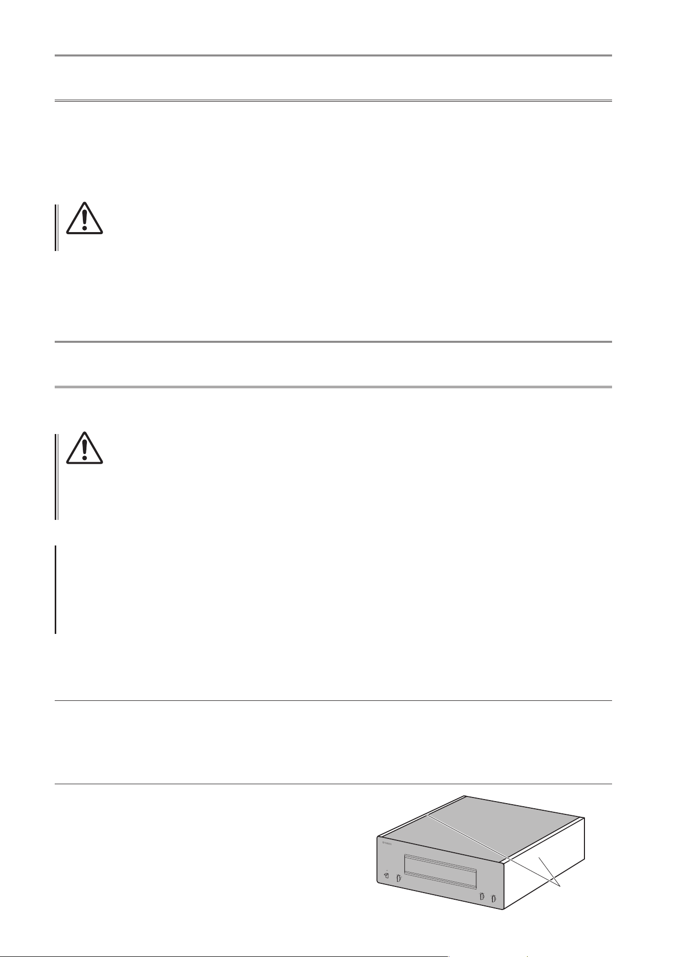
Mirror-nish side panels
We recommend that you use a cleaning cloth such as those made for pianos. If the surface is very dirty, use a soft cloth
that is damp with water and wrung tightly.
Surfaces other than the mirror-nish side panels
Wipe other surfaces using a soft dry cloth. If the surface gets
very dirty, dampen a cloth with detergent diluted in water,
wring the cloth tightly, and then wipe the dirt from the surface.
Mirror-nish
side panels

5
English
Part Names and Functions
This section describes the names and functions of the parts
on the front and rear panel.

6
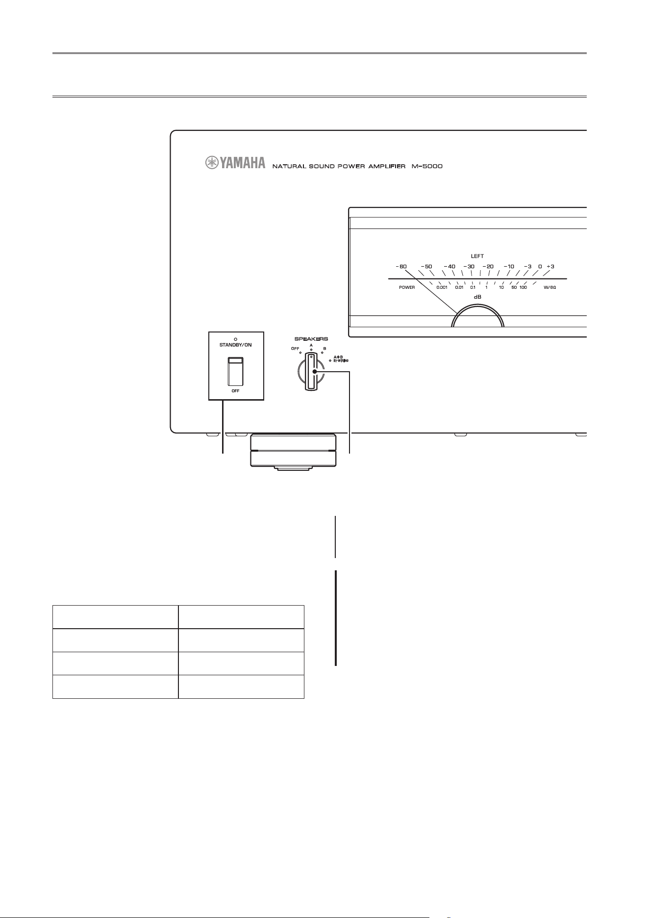
Front panel
A.
STANDBY/ON/OFF (Power)
switch/indicator
Turns the power to the unit on or off.
STANDBY/ON
: Turns the power to the unit on.
OFF
: Turns the power to the unit off.
Power status Indicator
On mode Lit brightly
Standby mode Lit dimly
O mode Off
The unit will enter standby mode in one of the following
events:
• If the unit is powered on but not operated for eight
hours while the auto power standby function is turned
on, or
• If you turn off the power to the device that is connected
to this unit’s TRIGGER IN jack.
For more information, refer to “
G
AUTO POWER
STANDBY switch” in the “Rear panel” section
(page 9) and to “Trigger connections” (page 13).
Note
After you turn on the unit, it will take a few seconds before
the unit can reproduce sound.
NOTICE
If you plan not to use the unit for an extended period of
time, be sure to unplug the power cord from the AC outlet.
Even when the STANDBY/ON/OFF (Power) switch is turned
o (the power indicator is dark), a minimal amount of
electric current is still owing to the unit.
B.
SPEAKERS selector
Turns on or off two sets of speakers connected to the
SPEAKERS A and B terminals on the rear panel.
OFF
: Both sets of speakers are off.
A
: The set of speakers connected to the A terminal is on.
B
: The set of speakers connected to the B terminal is on.
A+B/BI-WIRING
: Both sets of speakers are on.
A MPLIFIER
POWER
NATURAL SOUND
SPEAKERS
OFF
A
B
A
+
B
WIRING
BI
METER
OFF
PEAK
INPUT
LINE
BAL
VU
DIMMER
7
English
NOTICE
Make sure that the impedance of each speaker is
appropriate for the system conguration. For more
information, refer to “Basic speaker connections”
(page14), “Bi-wiring connections” (page18), “Bi-
amp connections” (page20), and “Bridge connections”
(page22).
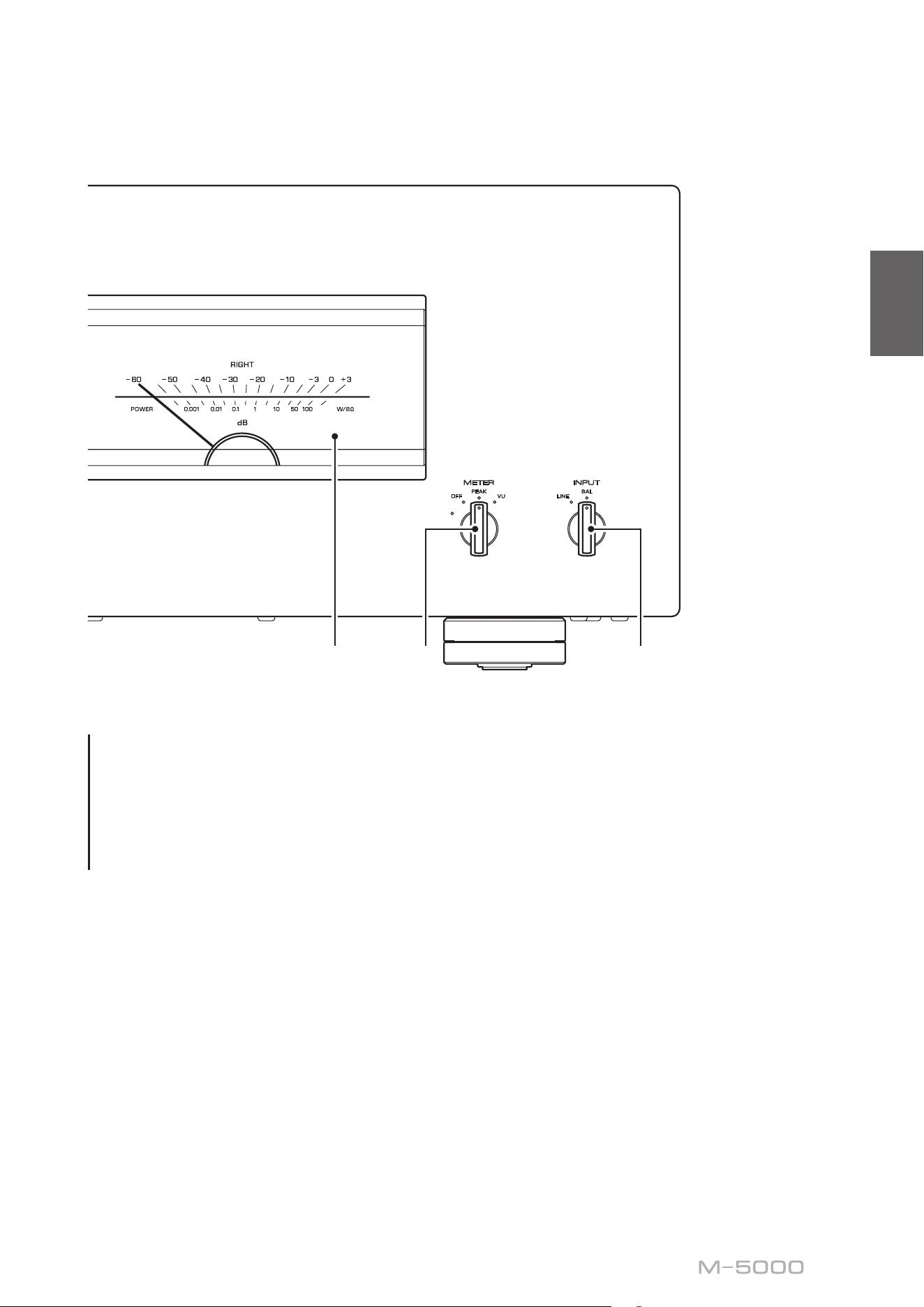
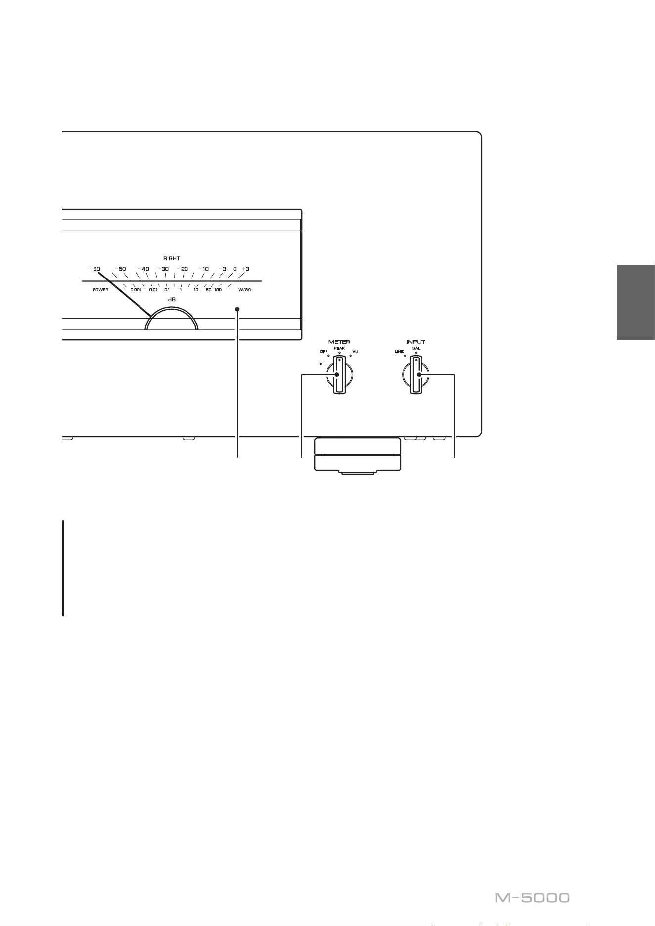
C.
Meter display (LEFT/RIGHT)
Indicates the audio output level of the left and right
channels.
D.
METER selector
Switches the meter display type to OFF, PEAK, or VU.
DIMMER
: Adjusts the brightness of the meter display.
The brightness will change slowly between the brightest
and darkest (off). When you select the meter type by
turning the METER selector, the brightness at that point
will be used for the display.
OFF
: Turns off meter operation and display illumination.
PEAK
: Switches the meter display type to a peak
level meter. The peak level meter shows the highest
instantaneous level of an audio output signal.
VU
: Switches the meter display type to a VU (Volume
Unit) level meter. The VU level meter shows an effective
audio output value that represents the way sound is
perceived by human ears.
E.
INPUT selector
Enables you to select jacks to play back an audio source.
LINE
: Audio source input from the LINE jacks will be
played back.
BAL
: Audio source input from the BAL jacks will be
played back.
A MPLIFIER
POWER
NATURAL SOUND
SPEAKERS
OFF
A
B
A
+
B
WIRING
BI
METER
OFF
PEAK
INPUT
LINE
BAL
VU
DIMMER

8
Note
For information regarding the connection procedure, refer
to “Connections” (page11).
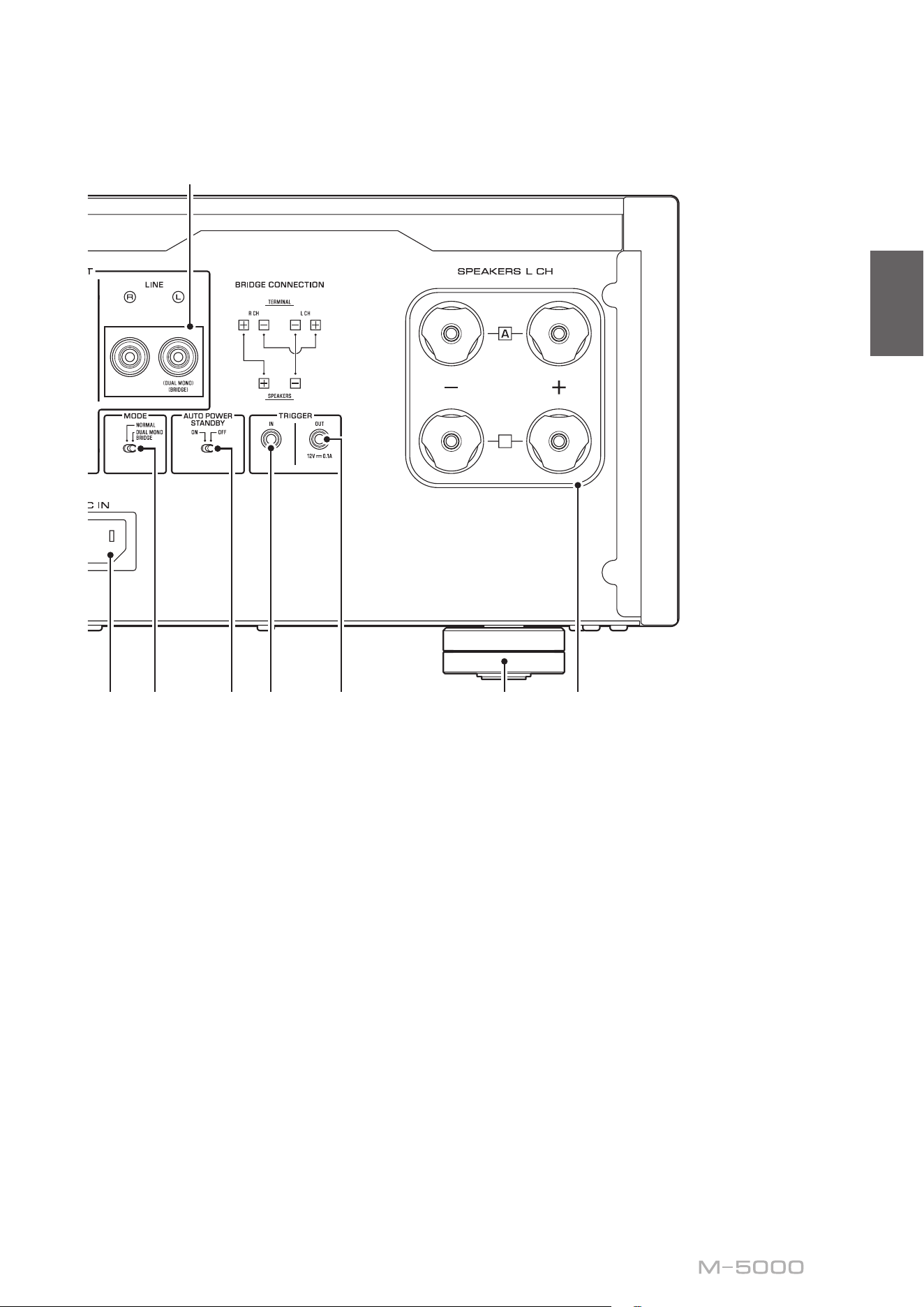
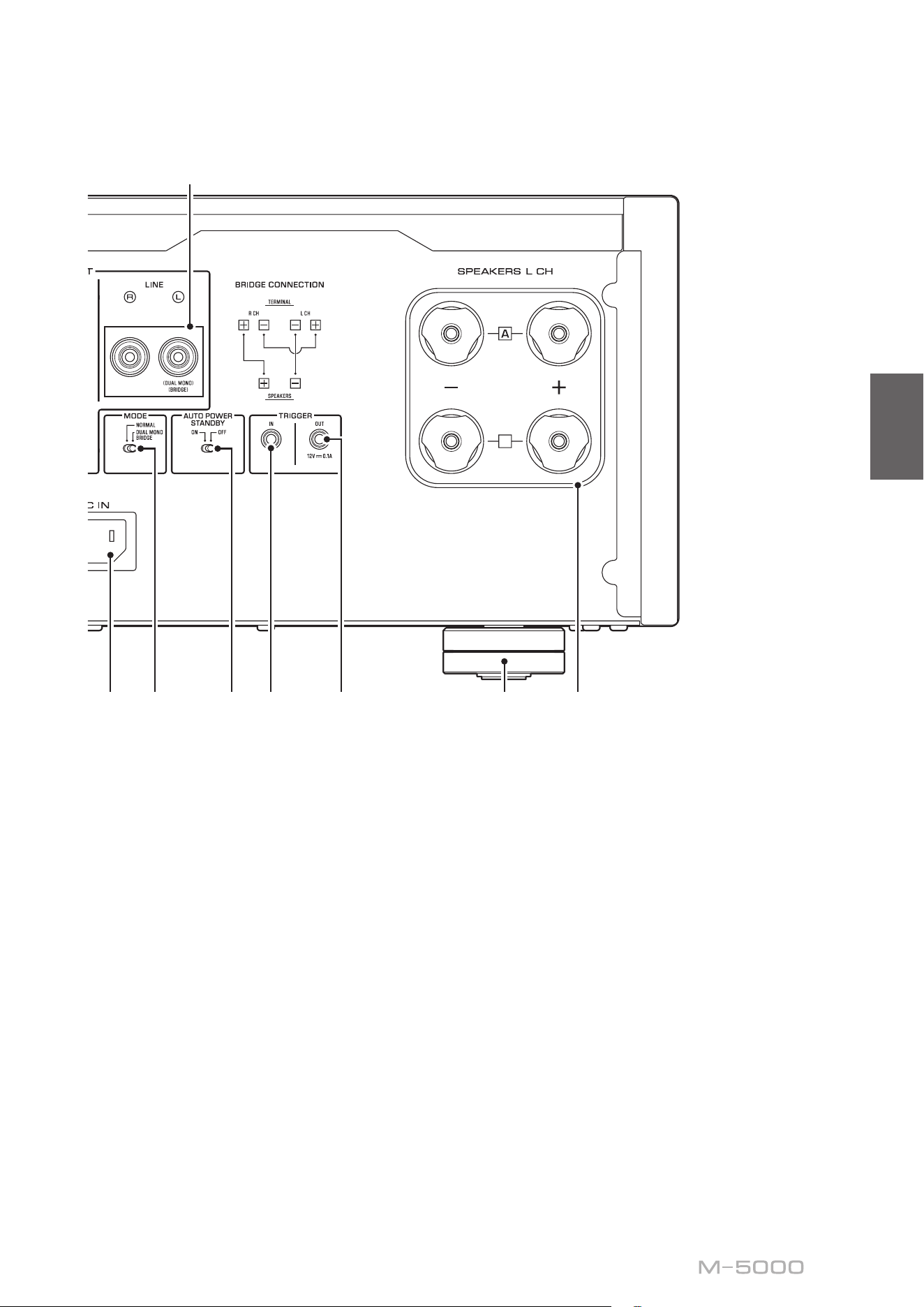
A.
SPEAKERS R CH output terminals
B.
SPEAKERS L CH output terminals
Use the included speaker cables to connect speakers to
the terminals. For information regarding the connection
procedure, refer to “Connections” (page 11).
C.
BAL input jacks
These are XLR-type balanced input jacks. Connect your
preamplier here. Set the PHASE selector appropriately
for the connected preamplier.
D.
PHASE selector
Sets the position (polarity) of the HOT pin at the BAL
input jacks according to the connected preamplier. For
more information, refer to “Balanced and unbalanced
connections” (page 10).
NORMAL
: Pin #2 is specied as HOT.
INVERTED
: Pin #3 is specied as HOT.
Refer to the instruction manual for the connected
component to nd out the position of the HOT pin at the
balanced output jacks on the component.
E.
LINE input jacks
These are RCA-type unbalanced input jacks. Connect
your preamplier here.
Rear panel
B
B
9
English
F.
MODE selector
Switches the speaker output between stereo and
monaural. For more information, refer to “Basic speaker
connections” (page 14), “Bi-wiring connections”
(page 18), “Bi-amp connections” (page 20), and
“Bridge connections” (page 22).
NORMAL
: The unit is used as a stereo amplier. This is
the standard setting.
DUAL MONO/BRIDGE
: The unit is used as a monaural
amplier. Select this setting for bi-amp or bridge
connections.
G.
AUTO POWER STANDBY switch
ON
: The unit enters standby mode automatically if it
is powered on but not operated for eight hours. This
function is disabled if the system cable is connected to
the TRIGGER IN jack.
OFF
: The unit does not enter standby mode automatically.
H.
TRIGGER IN jack
I.
TRIGGER OUT jack
Used to connect a component that supports the trigger
function so that you can control the unit’s power on and
off from that component. For more information, refer to
“Trigger connections” (page 13).
J.
SERVICE jack
This jack is used to test the product.
K.
AC IN jack
Connect the supplied power cord here. For more
information, refer to “Connecting the power cord”
(page 24).
L.
Feet
If the unit is unstable, adjust the height of the feet as
needed by rotating them.
B
B
10
Balanced and unbalanced
connections
This unit features balanced input jacks (BAL) and
unbalanced input jacks (LINE).
NOTICE
Do not use balanced and unbalanced connections between
two components simultaneously. Doing so would create a
ground loop that could generate static and noise.
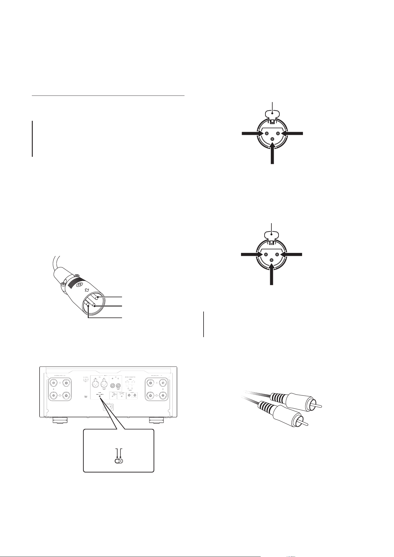
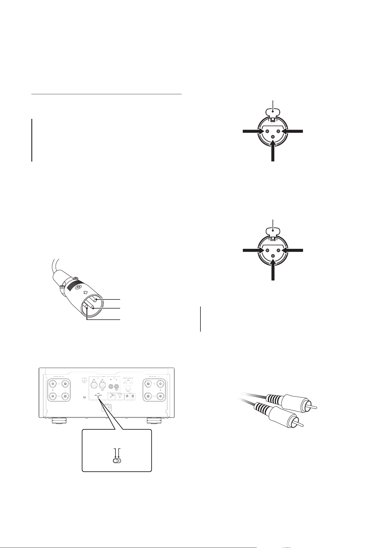
Balanced connection
A balanced connection is a great advantage against
external noise. For a balanced connection, use a cable
with male XLR connectors. When connecting a cable, be
sure to align the pins on the connector with the holes on
the jack, and then insert the connector into the jack until
you hear a click. To remove the cable, while pressing
and holding down the lever on the BAL jack, pull out the
male XLR connector from the jack.
Pin #2
Pin #3
Pin #1
When making a balanced connection, you must set the
polarity correctly. To set the polarity, use the PHASE
selector on the rear panel.
B
B
B
B
PHASE
NORMAL
INVERTED
If the PHASE selector is set to NORMAL, pin #2
becomes HOT.
1: ground (earth)
3: cold
2: hot
Lever
If the PHASE selector is set to INVERTED, pin #3
becomes HOT.
1: ground (earth)
3: hot
2: cold
Lever
Note
Select NORMAL (pin #2 is HOT) for a Yamaha player or
preamplier.
Unbalanced connection
For an unbalanced connection, use RCA-type pin cables.
They do not transmit phase information.

11
English
Connections
This section explains how to connect the unit
to a preamplier and speakers.
CAUTION
Turn o the power to all components before making any connections.
NOTICE
Before you connect external components, read and follow the instruction manuals for those components. Otherwise, this unit or
external components might malfunction.

12
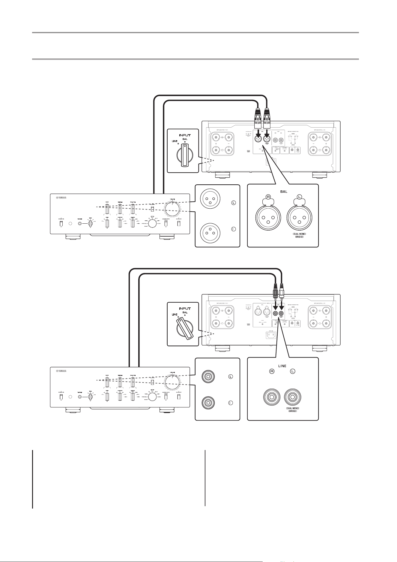
Connecting a preamplier
Connect your preamplier to the unit’s input jacks. For this connection, use XLR-type balanced cables or RCA-type
unbalanced cables.
Balanced connection
Unbalanced connection
INPUT
LINE
BAL
B
B
B
B
M-5000
R
BAL
Preamplier
XLR-type balanced cable
INPUT
LINE
BAL
B
B
B
B
LINE 1
M-5000
R
Preamplier
RCA-type pin cable
NOTICE
The unit’s volume level is xed. Do not connect a
component that does not feature volume adjustment to
the unit’s input jacks. Otherwise, a loud sound might be
emitted, resulting in malfunction of the unit or damage to
the speakers.
Note
• If the preamplier supports both balanced and
unbalanced connections, use a balanced connection.
• Do not use balanced and unbalanced connections
between two components simultaneously. Doing so
would create a ground loop that could generate static and
noise.
Front panel
Front panel
13
English
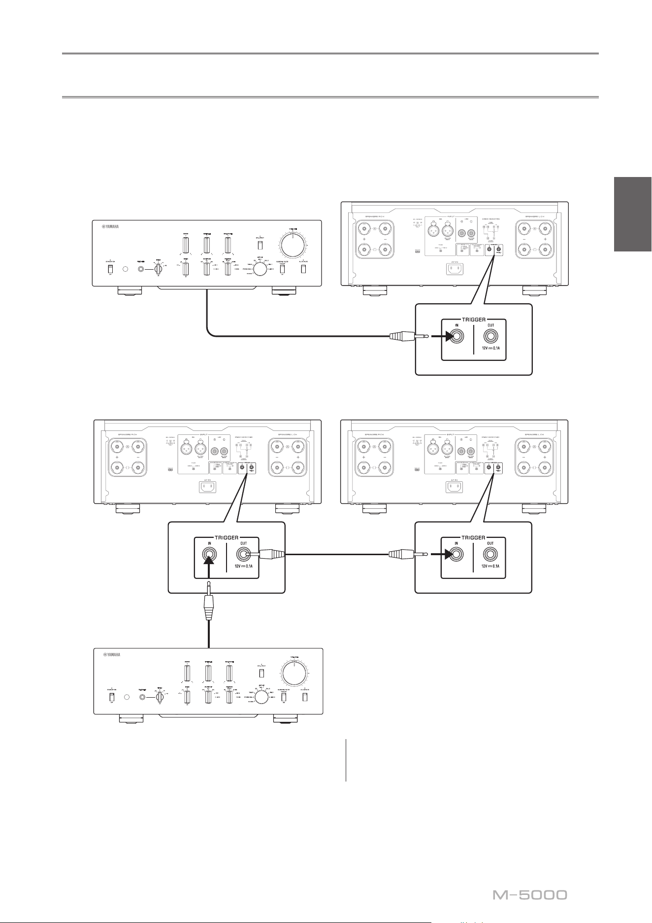
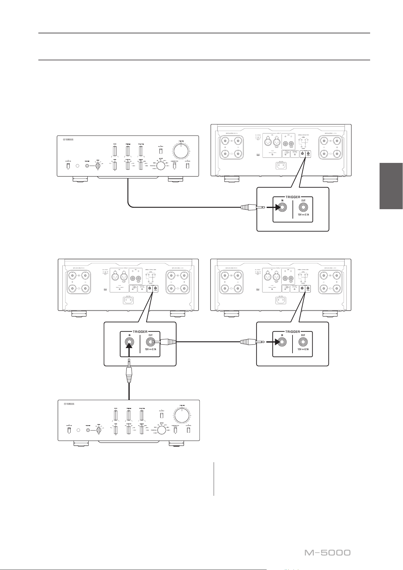
Trigger connections
You can control the unit’s power on and off in sync with a connected Yamaha component, such as a preamplier or AV
receiver.
Use the supplied system cable to make connections as shown in the following diagram.
Example (one M-5000 unit is used)
B
B
B
B
M-5000
Preamplier, etc
System cable
Example (two M-5000 units are used)
B
B
B
B
B
B
B
B
M-5000M-5000
Preamplier, etc
System cable
System cable
To control the unit in a trigger connection conguration,
set the STANDBY/ON/OFF (Power) switch to
STANDBY/ON.
When the power to the connected component is turned
on, the power to this unit is also turned on. When the
power to the connected component is turned off, this unit
enters standby mode.
Note
When the power switch on this unit is turned OFF, the
power to the unit will not be triggered.
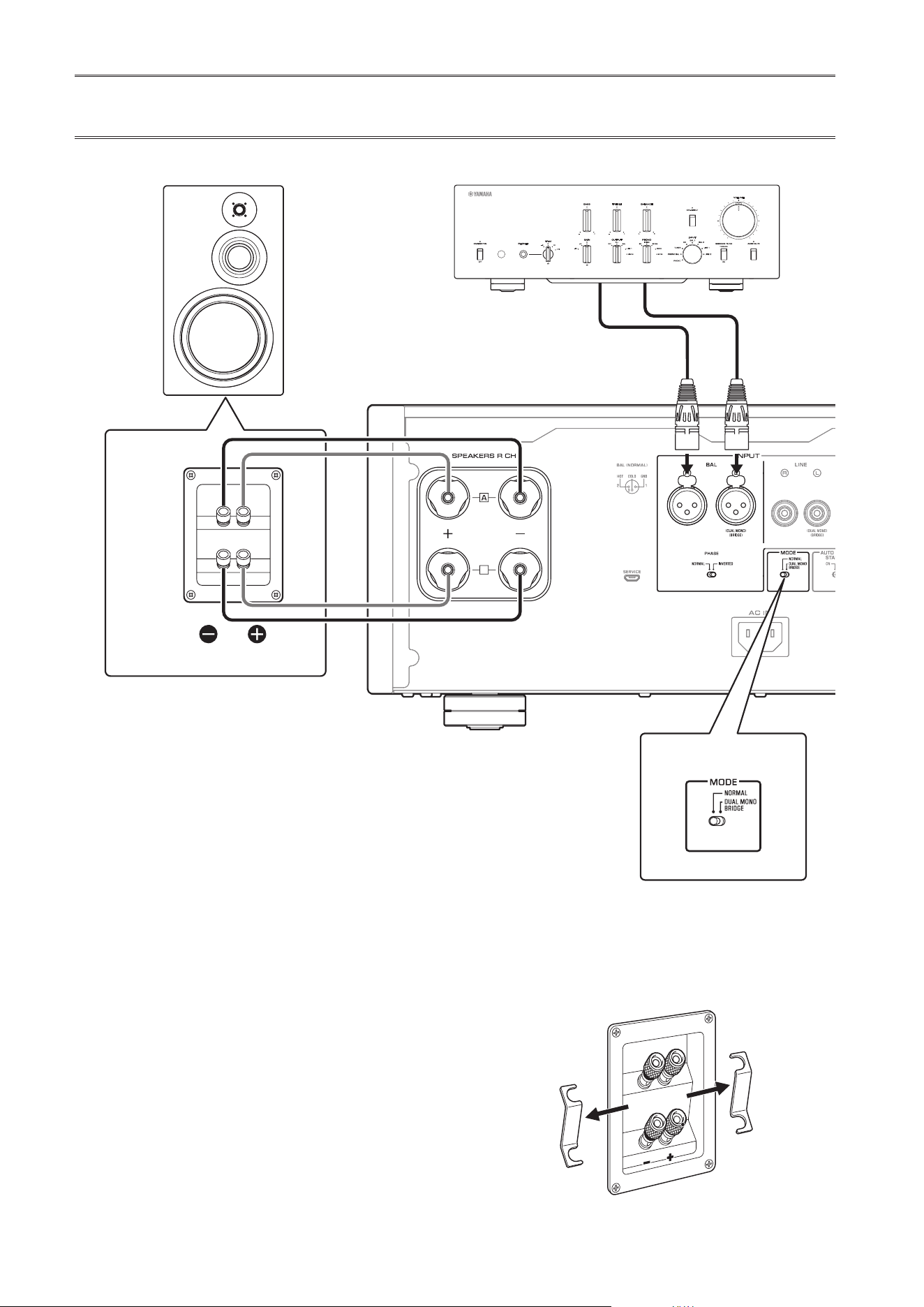
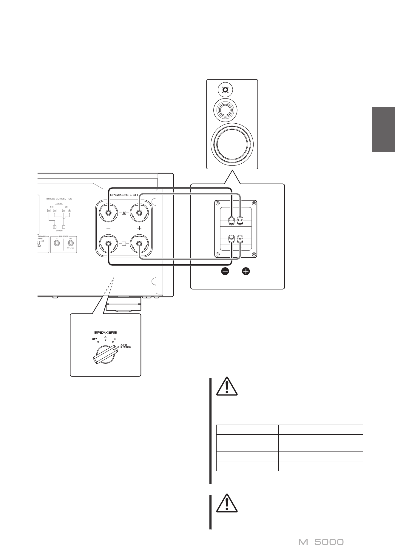
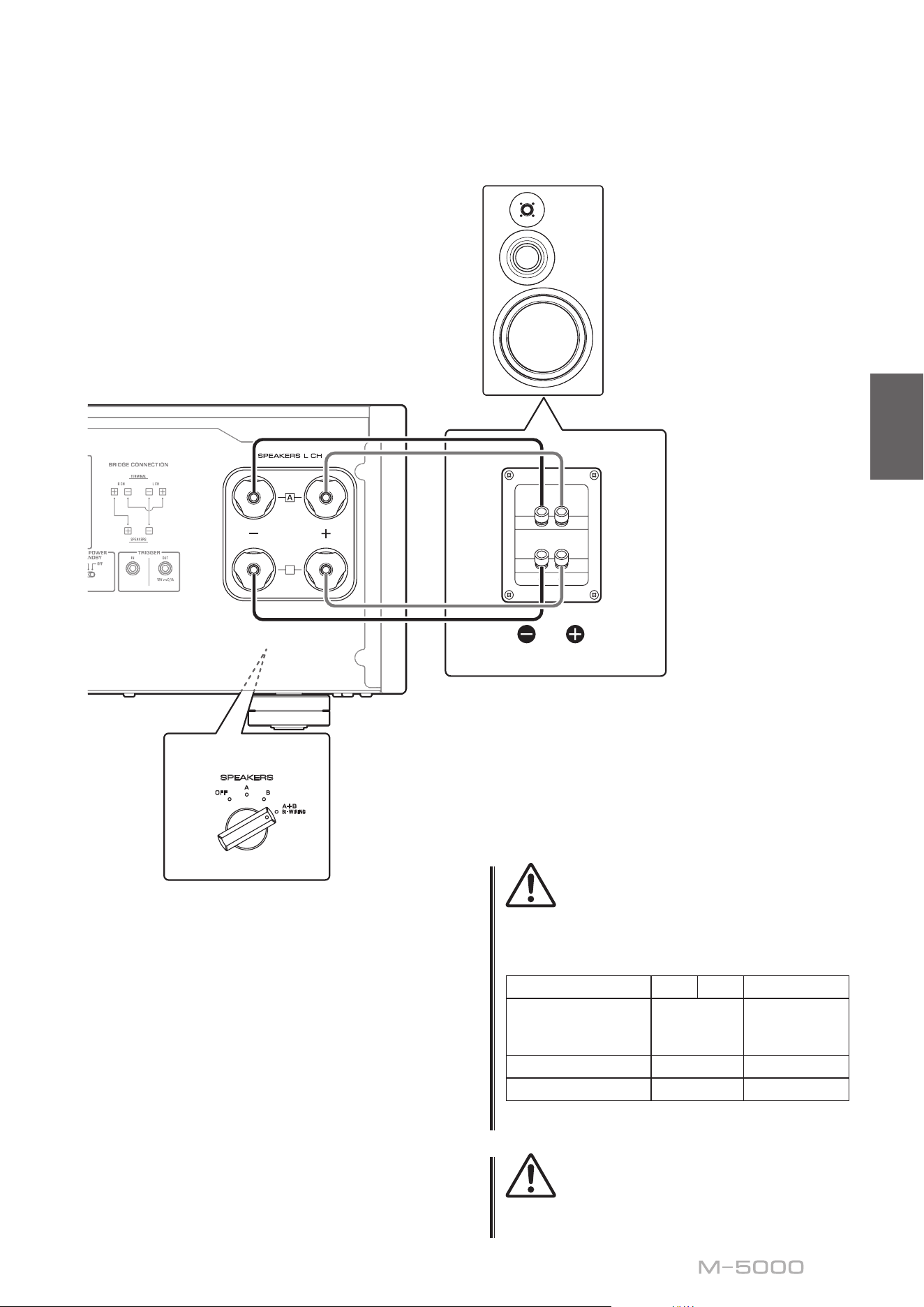
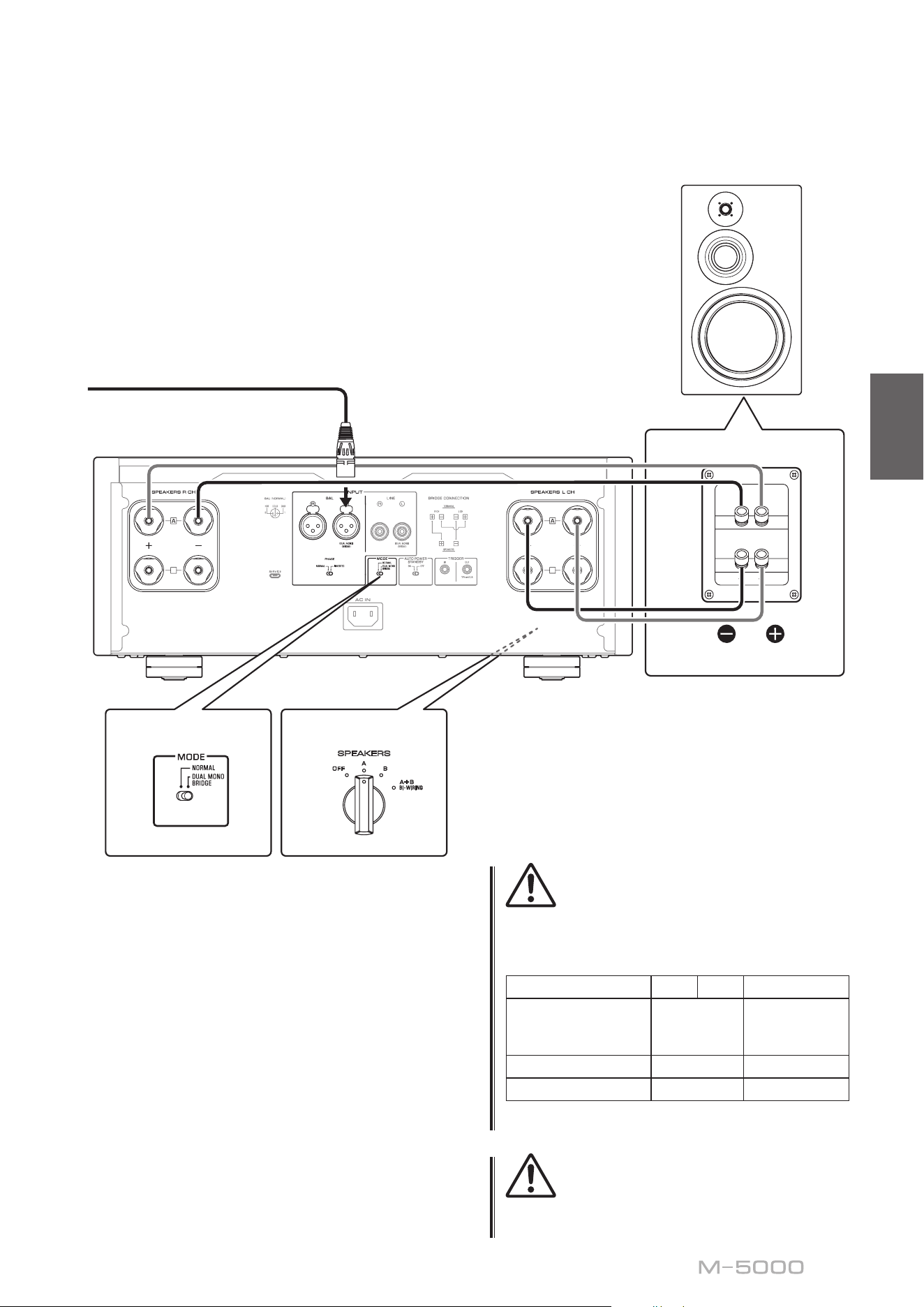
14
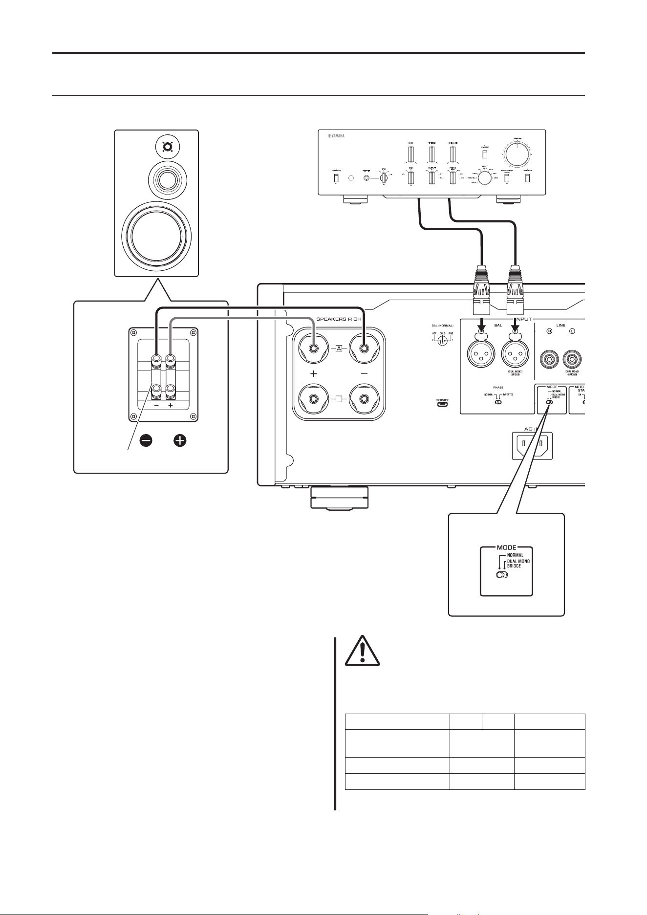
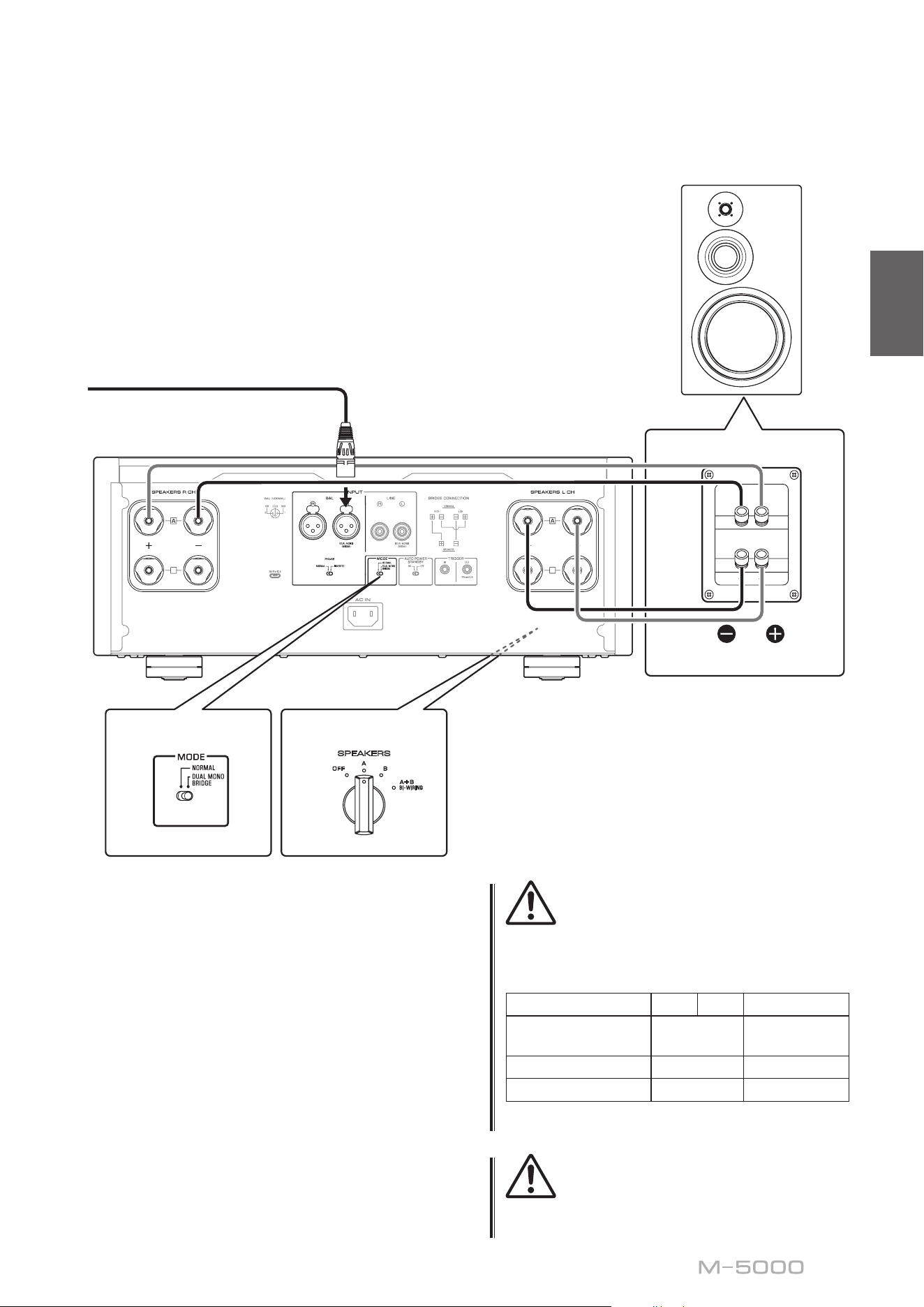
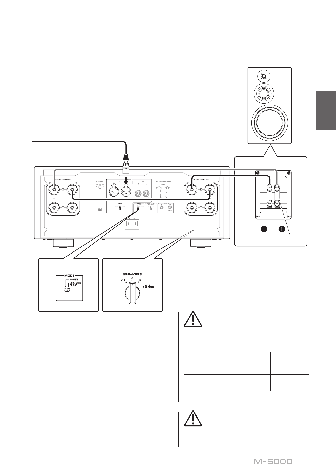
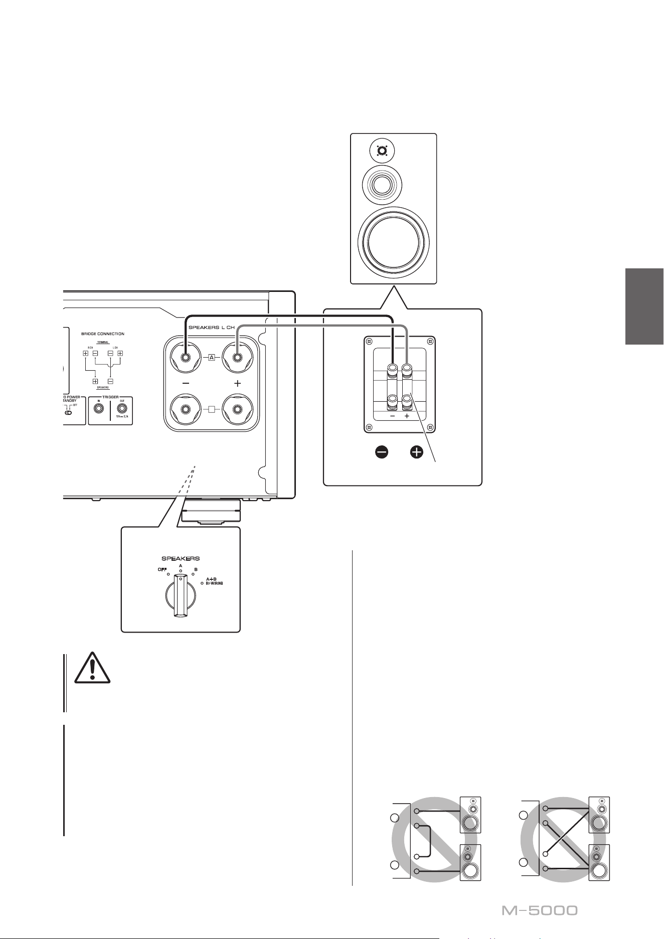
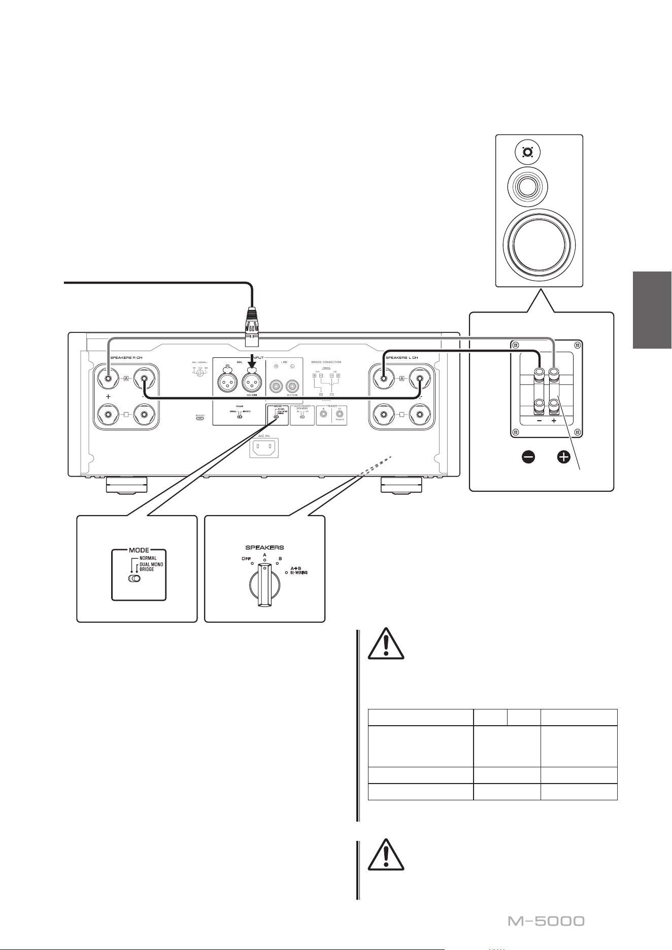
Basic speaker connections
1
Turn o the power to the unit and all
connected components
2
Set the MODE selector on the rear panel to
NORMAL
3
Set the SPEAKERS selector on the front
panel to A, B, or A+B BI-WIRING
The diagram shows the selector set to A.
4
Connect the power amplier to the “+” and
“−” terminals of the speakers
CAUTION
Be sure to use speakers that feature the impedance shown
in the table below.
Speaker impedance
SPEAKERS selector A B A+B
Basic connection/
Bi-wiring connection
4Ω or higher 8Ω or higher
Bi-amp connection 4Ω or higher 8Ω or higher
Bridge connection 8Ω or higher 16Ω or higher*
* Excluding models for U.S.A. and Canada
B
B
SPEAKERS
OFF
A
B
A
+
B
WIRING
BI
High
Low
High
Low
MODE: NORMAL
M-5000
MODE selector
Shorting bar
Preamplier
R channel
R channel L channel
R channel signal L channel signal
R channel
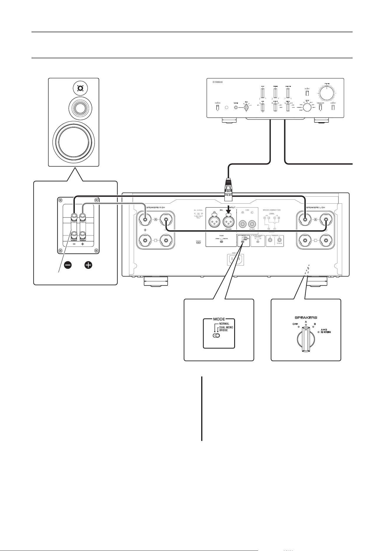
15
English
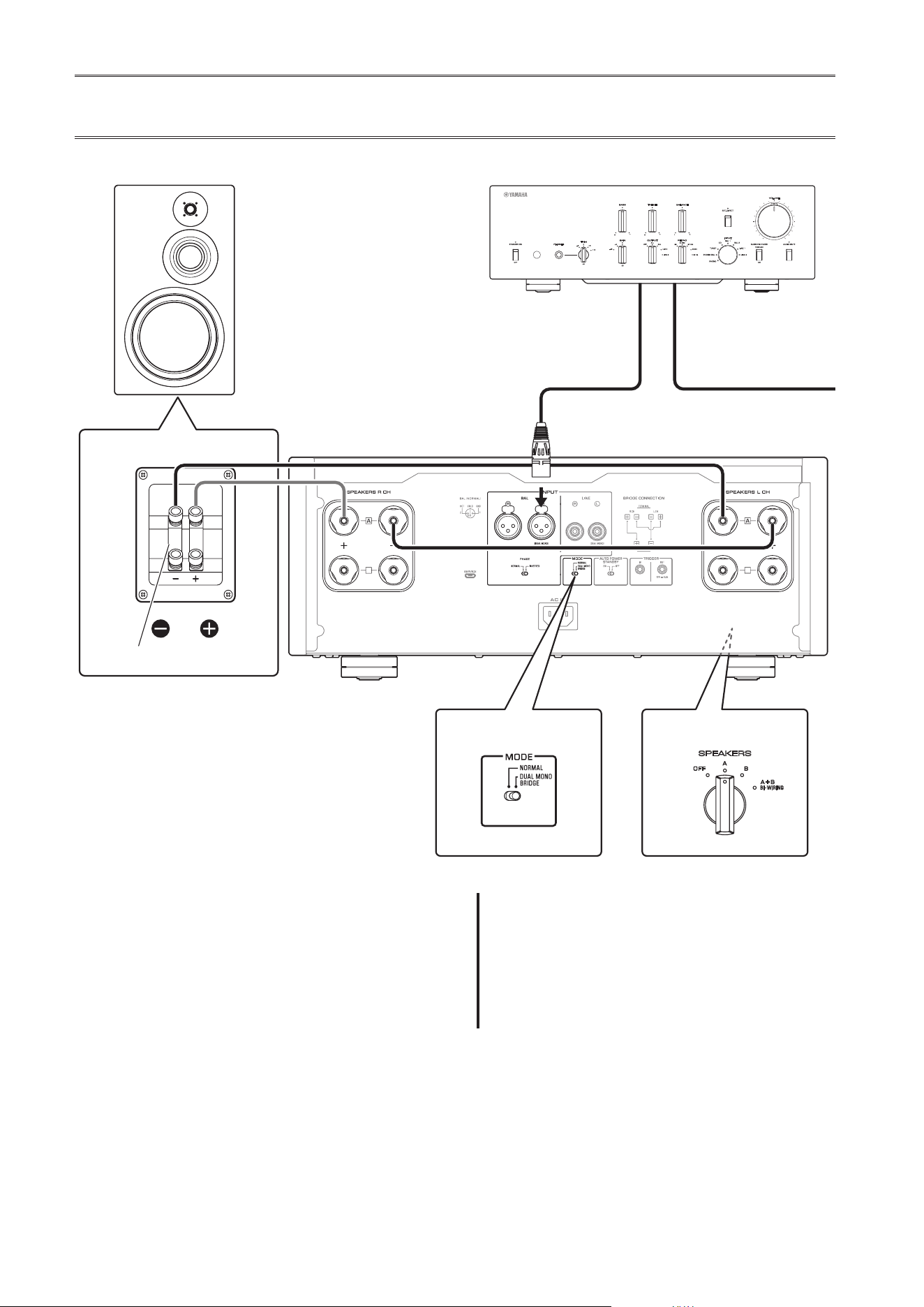
CAUTION
Before turning the power back on to the source
component, rst lower the volume level on that
component.
NOTICE
• Do not let the bare speaker wires touch each other, nor
let them touch any metal part of this unit. Otherwise, the
unit and/or the speakers might be damaged.
• Do not connect an active subwoofer to this unit. Connect
the subwoofer to the preamplier.
B
B
SPEAKERS
OFF
A
B
A
+
B
WIRING
BI
High
Low
High
Low
MODE: NORMAL
M-5000
Shorting bar
L channel
L channel
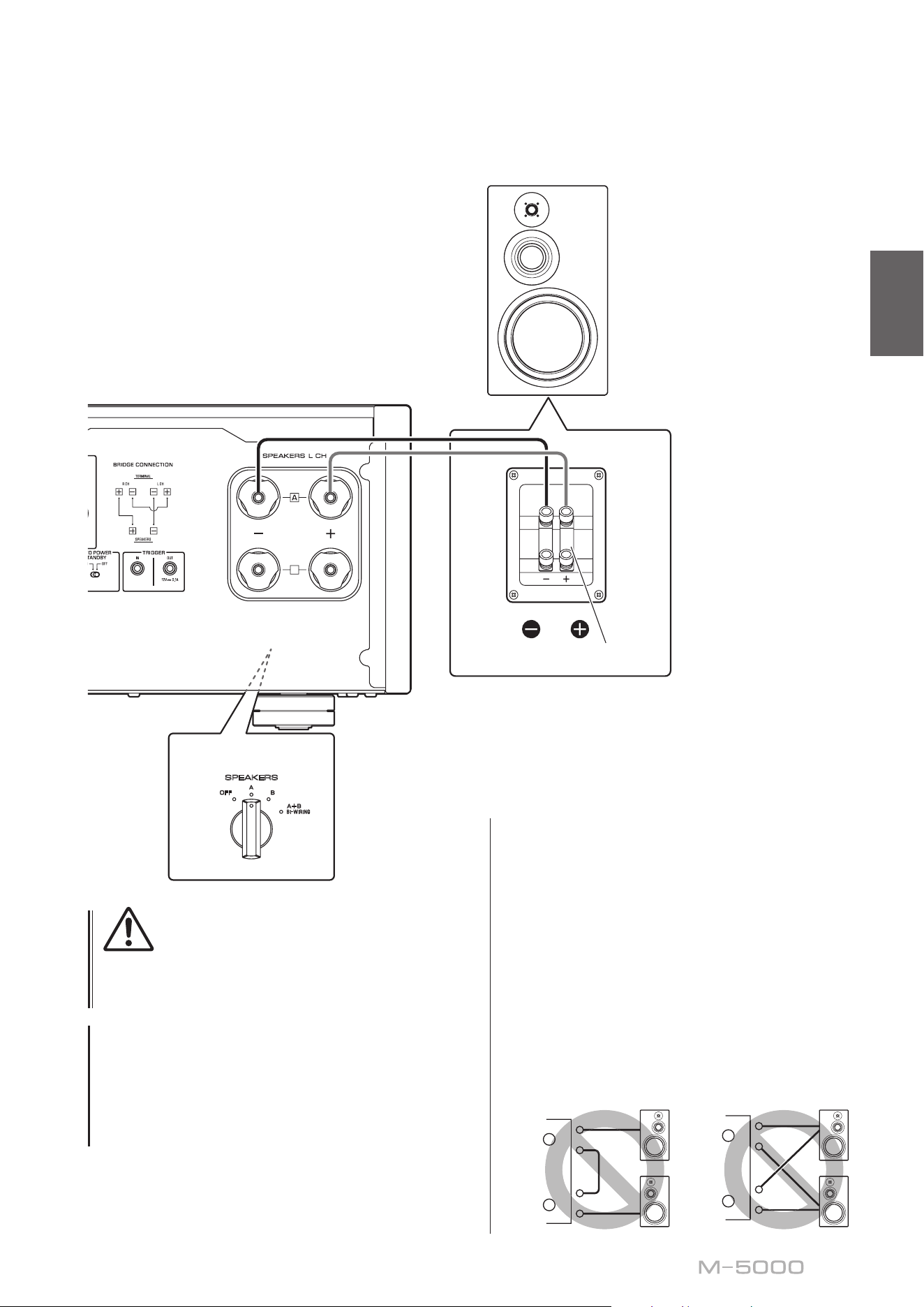
Note
• All connections must be correct: L (left) to L, R (right) to
R, “+” to “+”, and “−” to “−”. If the connections are faulty,
no sound will be heard from the speakers. Also, if the
polarity of the speaker connections is incorrect, the
sound will be unnatural and lack bass.
• Because this power amplier is of the oating balanced
type, the following types of connections are not possible.
- Connecting between two “+” (or two “−”) terminals of
the left and right channels (Fig. 1).
- Connecting each “−” terminal of the unit’s left and
right channels to the opposite channel speakers
(cross connection, Fig. 2).
- Connecting the left/right channel “−” terminals (or
accidentally allowing them to come in contact) with
the metal part of the rear panel of this unit.
+
–
+
–
L
R
+
–
+
–
L
R
+
–
+
–
L
R
+
–
+
–
L
R
Figure
1
Figure
2
SPEAKERS selector
(front panel)
16
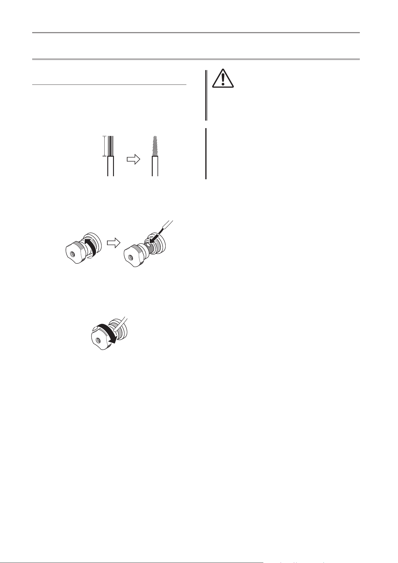
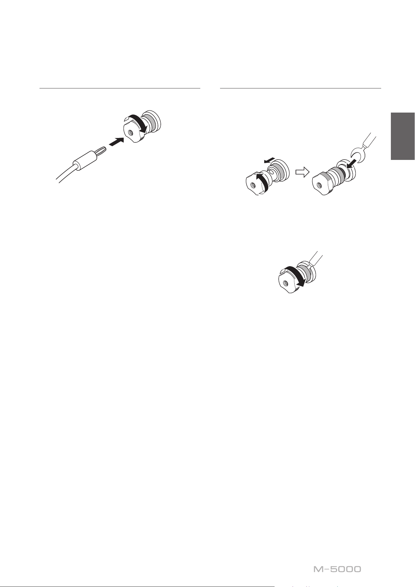
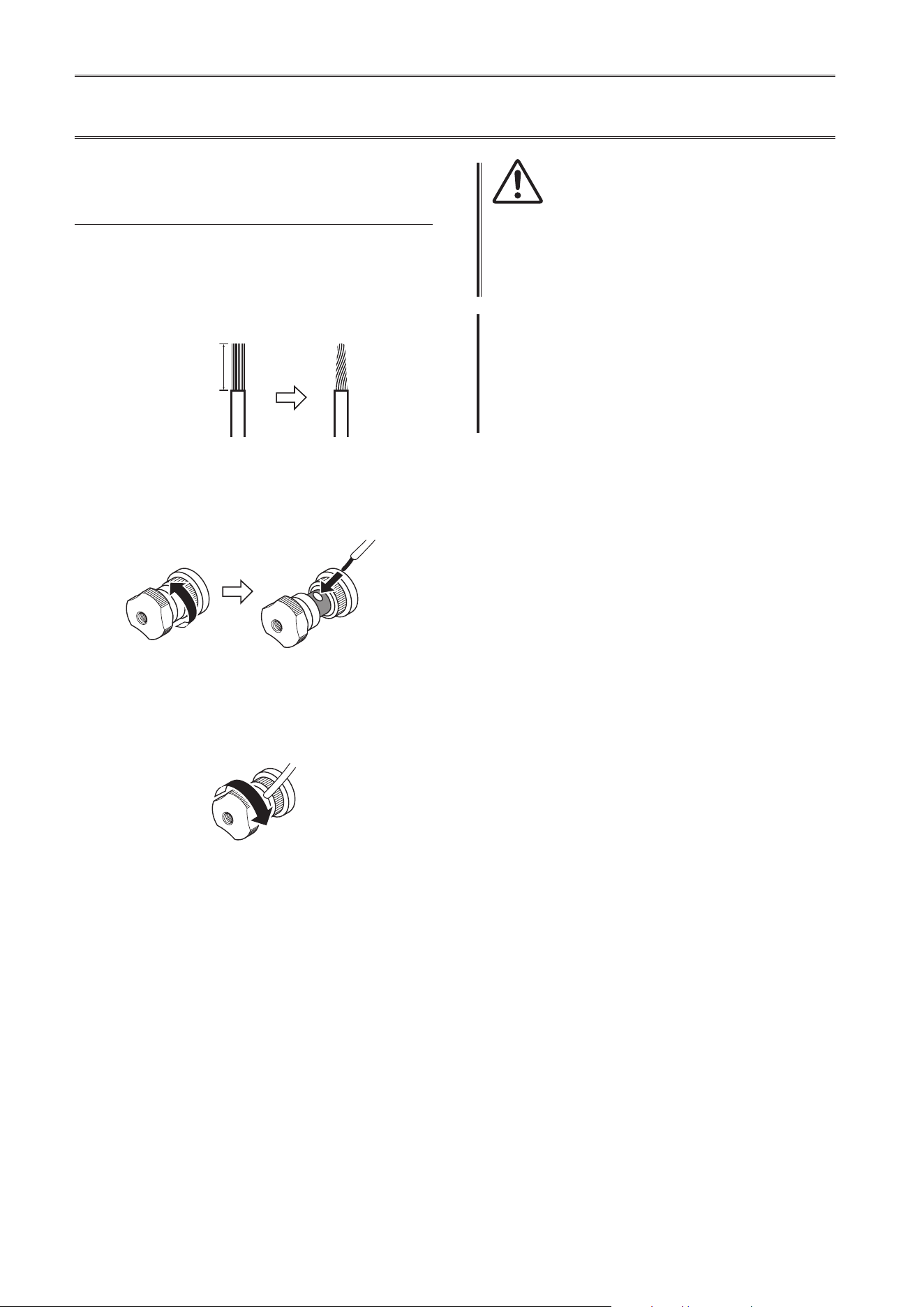
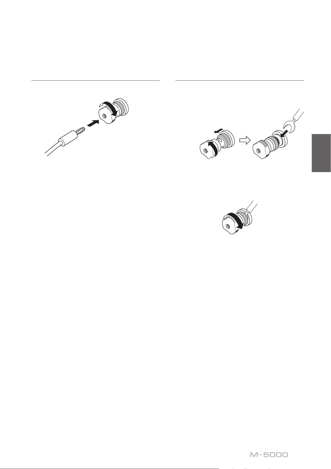
Connecting speaker cables
Using standard speaker cables
1
Remove approximately 10 mm (0 4 in) of
insulation from the end of each speaker
cable, and twist the exposed wires
together tightly to prevent short circuits
10 mm (0 4 in)
2
Unscrew the knob on each SPEAKERS
terminal, and then insert the bare wire into
the side hole on the terminal
Diameter of the speaker cable
wire hole: 6 0 mm (0 24 in)
3
Tighten the knob
CAUTION
• Do not loosen the knob excessively. Otherwise, the knob
might come o and a child might swallow it accidentally.
• To reduce the risk of electric shock, do not touch the
SPEAKERS terminals while the power to the unit is on.
NOTICE
If the SPEAKERS terminals come into contact with a metallic
rack, a short circuit might occur, resulting in damage to this
unit. When installing the unit in a rack, maintain a sucient
clearance to prevent the SPEAKERS terminals from coming
into contact with the rack.
17
English
Using banana plug cables
First, tighten the knob, and then insert the banana plug
into the head of the knob.
Diameter of the banana
plug hole: 5 5 mm (0 22 in)
Using Y-shaped lug cables
1
Unscrew the knob, and then sandwich the
Y-shaped lug between the ring part and
base of the terminal
Thickness of the
terminal core: 5 0 mm (0 20 in)
Slide
Y-shaped lug
2
Tighten the knob
18
Bi-wiring connections
To bi-wire your speakers, separate cables are used to
connect the mid/high-frequency speaker driver (tweeter)
and the low-frequency driver (woofer) on each bi-
wireable speaker to the amplier. Running separate
cables from the amplier can have a profound impact on
relieving the tweeter circuit from the back ush of EMF
(electromotive force) generated by the woofer’s voice
coil, resulting in less interference between HF and LF
ranges and better sound quality.
You need to use speakers that feature two sets of
terminals (total of four) that allow each speaker to be split
into two sections (low-frequency and mid/high-frequency
ranges).
1
Turn o the power to the unit and all
connected components
2
Remove the shorting bars or bridges on
the speakers
The LPF (low pass lter) and HPF (high pass
lter) crossovers will be separated.
B
B
High
Low
High
Low
MODE: NORMAL
M-5000
SPEAKERS
OFF
A
B
A
+
B
WIRING
BI
MODE selector
Remove the shorting bar
PreamplierR channel
R channel L channel
R channel signal L channel signal
R channel
19
English
3
Connect the power amplier to the
speakers
For each channel speaker, connect the cables
from the speaker’s mid/high range terminals
to the amplier’s SPEAKERS A jacks of the
corresponding channel, and from the speaker’s
low range terminals to the amplier’s SPEAKERS
B jacks of the corresponding channel respectively.
4
Set the MODE selector on the rear panel to
NORMAL
5
Set the SPEAKERS selector on the front
panel to A+B BI-WIRING
CAUTION
Be sure to use speakers that feature the impedance shown
in the table below.
Speaker impedance
SPEAKERS selector A B A+B
Basic connection/
Bi-wiring connection
4Ω or higher 8Ω or higher
Bi-amp connection 4Ω or higher 8Ω or higher
Bridge connection 8Ω or higher 16Ω or higher*
* Excluding models for U.S.A. and Canada
CAUTION
Before turning the power back on to the source component,
rst lower the volume level on that component.
B
B
High
Low
High
Low
MODE: NORMAL
M-5000
SPEAKERS
OFF
A
B
A
+
B
WIRING
BI
Remove the shorting bar
L channel
L channel
SPEAKERS selector
(front panel)
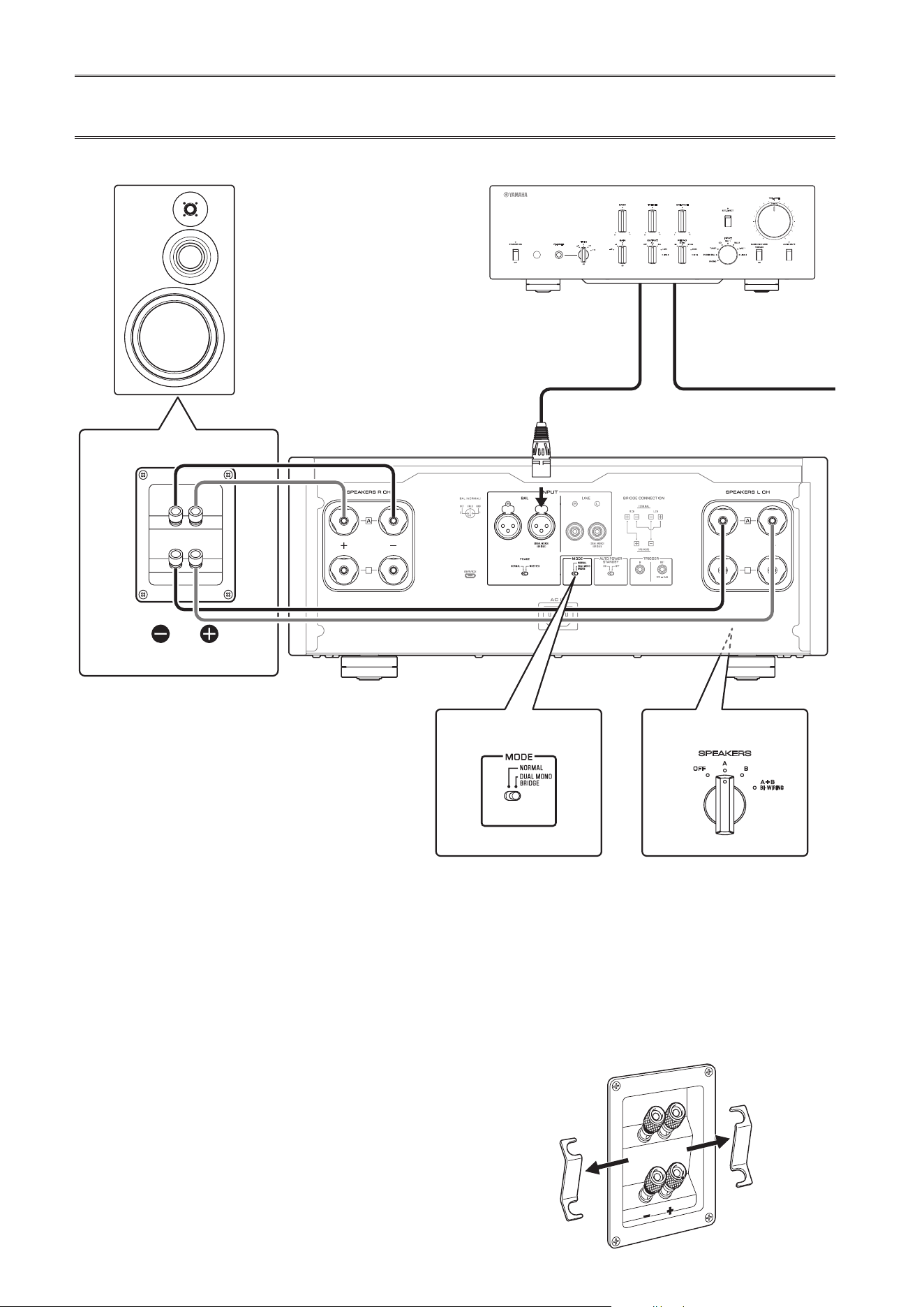
20
Bi-amp connections
To congure a bi-amp stereo system, you need two
M-5000 units.
The M-5000 features two built-in ampliers. Each of
these amps is connected to the mid/high-frequency
speaker driver (tweeter) and the low-frequency driver
(woofer) on the speaker of the corresponding channel.
You need to use speakers that feature two sets of
terminals (total of four) that allow each speaker to be split
into two sections (low-frequency and mid/high-frequency
ranges). Bi-amping speakers can prevent the back ush of
EMF (electromotive force) generated by the woofer from
affecting the signal, resulting in improved sound quality
in some cases.
Connect the input source to the L-channel input jacks on
both M-5000 units.
1
Turn o the power to the unit and all
connected components
2
Remove the shorting bars or bridges on
the speakers
The LPF (low pass lter) and HPF (high pass
lter) crossovers will be separated.
B
B
B
B
SPEAKERS
OFF
A
B
A
+
B
WIRING
BI
High
Low
High
Low
M-5000
M-5000
MODE: DUAL MONO/BRIDGE
SPEAKERS
OFF
A
B
A
+
B
WIRING
BI
MODE: DUAL MONO/BRIDGE
MODE selector
Remove the shorting bar
PreamplierR channel
R channel L channel
R channel signal L channel signal
R channel
SPEAKERS selector
(front panel)
21
English
3
Set the MODE selector on the rear panel to
DUAL MONO/BRIDGE
4
Set the SPEAKERS selector on the front
panel to A, B, or A+B BI-WIRING
The diagram shows the selector set to A.
5
Connect the power amplier (this unit) to
the speakers
For each channel speaker, connect the cables
from the speaker’s mid/high range terminals to
the amplier A jacks for the SPEAKERS R CH,
and from the speaker’s low range terminals to the
amplier A jacks for the SPEAKERS L CH.
CAUTION
Be sure to use speakers that feature the impedance shown
in the table below.
Speaker impedance
SPEAKERS selector A B A+B
Basic connection/
Bi-wiring connection
4Ω or higher 8Ω or higher
Bi-amp connection 4Ω or higher 8Ω or higher
Bridge connection 8Ω or higher 16Ω or higher*
* Excluding models for U.S.A. and Canada
CAUTION
Before turning the power back on to the source component,
rst lower the volume level on that component.
B
B
B
B
SPEAKERS
OFF
A
B
A
+
B
WIRING
BI
High
Low
High
Low
M-5000
M-5000
MODE: DUAL MONO/BRIDGE
SPEAKERS
OFF
A
B
A
+
B
WIRING
BI
MODE: DUAL MONO/BRIDGE
Remove the shorting bar
L channel
MODE selector
L channel
SPEAKERS selector
(front panel)
22
Bridge connections
In a bridge connection conguration, the M-5000 is used
as a monaural amplier. To create a stereo system, you
need two M-5000 units.
On each amplier, connect the “+” terminal of the
SPEAKERS L CH to the “−” terminal of the SPEAKERS
R CH. For this connection, use a cable that features the
same material as the speaker cables, and a length of 1.0 m
or less and a cross-sectional area of 1.0 mm
2
or larger. Do
not bundle the cable.
Connect the input source to the L-channel input jacks on
both M-5000 units.
NOTICE
Since amplication will be doubled in this conguration,
adjust the volume level appropriately on the connected
preamplier. If you are using a Yamaha preamplier that
features a GAIN selector, adjust the volume level using this
selector so that you will be able to use volume controls on
other components in the usual way.
1
Turn o the power to the unit and all
connected components
2
Set the MODE selector on the rear panel to
DUAL MONO/BRIDGE
B
B
B
B
MODE: DUAL MONO/BRIDGE
SPEAKERS
OFF
A
B
A
+
B
WIRING
BI
SPEAKERS
OFF
A
B
A
+
B
WIRING
BI
High
Low
High
Low
MODE: DUAL MONO/BRIDGE
M-5000
M-5000
Shorting bar
MODE selector
PreamplierR channel
R channel L channel
R channel signal L channel signal
R channel
SPEAKERS selector
(front panel)
23
English
3
Set the SPEAKERS selector on the front
panel to A, B, or A+B BI-WIRING
The diagram shows the selector set to A.
4
On each amplier, connect the “+” terminal
of the SPEAKERS L CH to the “−” terminal
of the SPEAKERS R CH
5
Connect the “+” terminal of the SPEAKERS
R CH to the speaker’s “+” terminal, and the
“−” terminal of the SPEAKERS L CH to the
speaker’s “−” terminal
CAUTION
Be sure to use speakers that feature the impedance shown
in the table below.
Speaker impedance
SPEAKERS selector A B A+B
Basic connection/
Bi-wiring connection
4Ω or higher 8Ω or higher
Bi-amp connection 4Ω or higher 8Ω or higher
Bridge connection 8Ω or higher 16Ω or higher*
* Excluding models for U.S.A. and Canada
CAUTION
Before turning the power back on to the source
component, rst lower the volume level on that
component.
B
B
B
B
MODE: DUAL MONO/BRIDGE
SPEAKERS
OFF
A
B
A
+
B
WIRING
BI
SPEAKERS
OFF
A
B
A
+
B
WIRING
BI
High
Low
High
Low
MODE: DUAL MONO/BRIDGE
M-5000
M-5000
Shorting bar
MODE selector
L channel
L channel
SPEAKERS selector
(front panel)
24
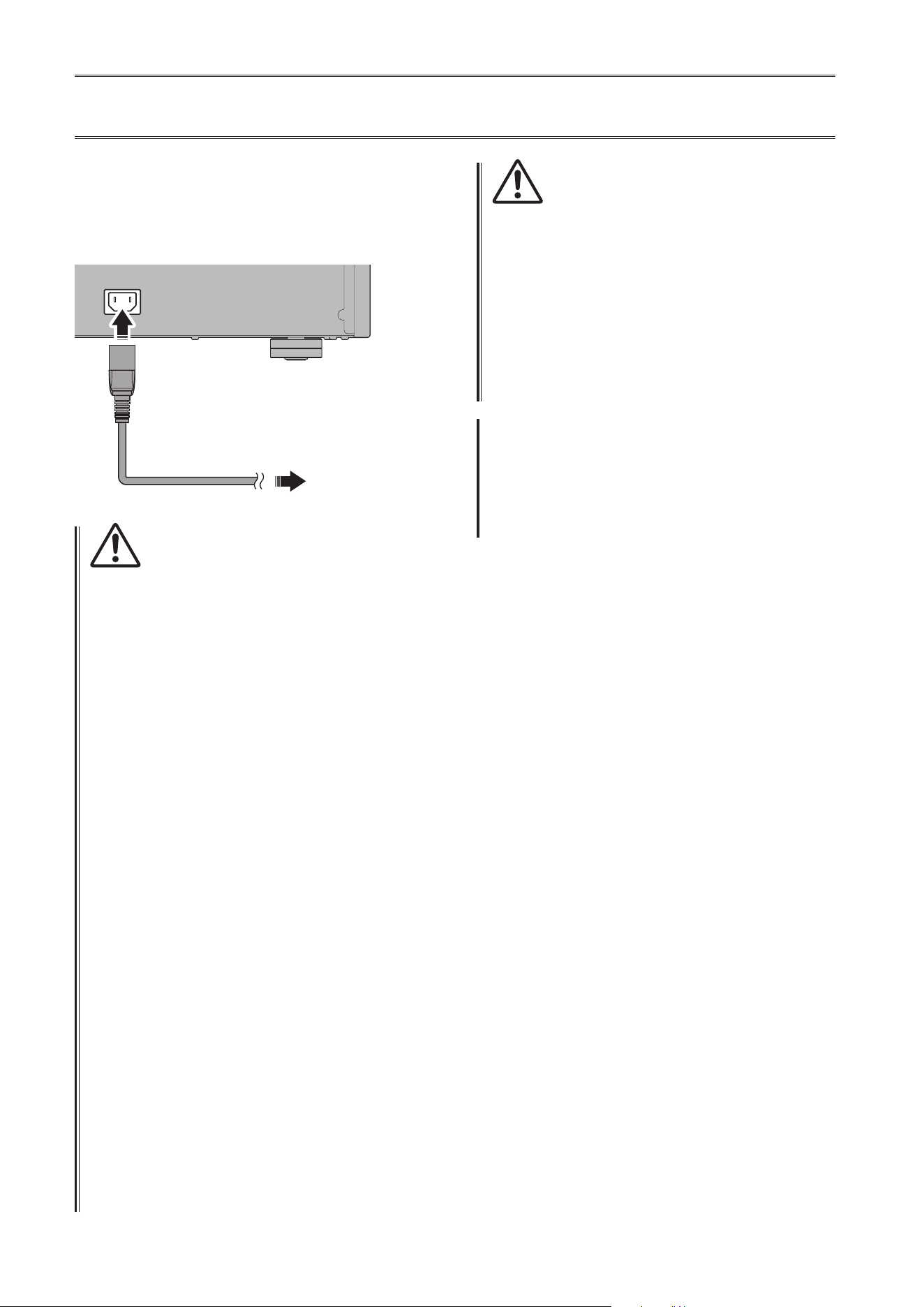
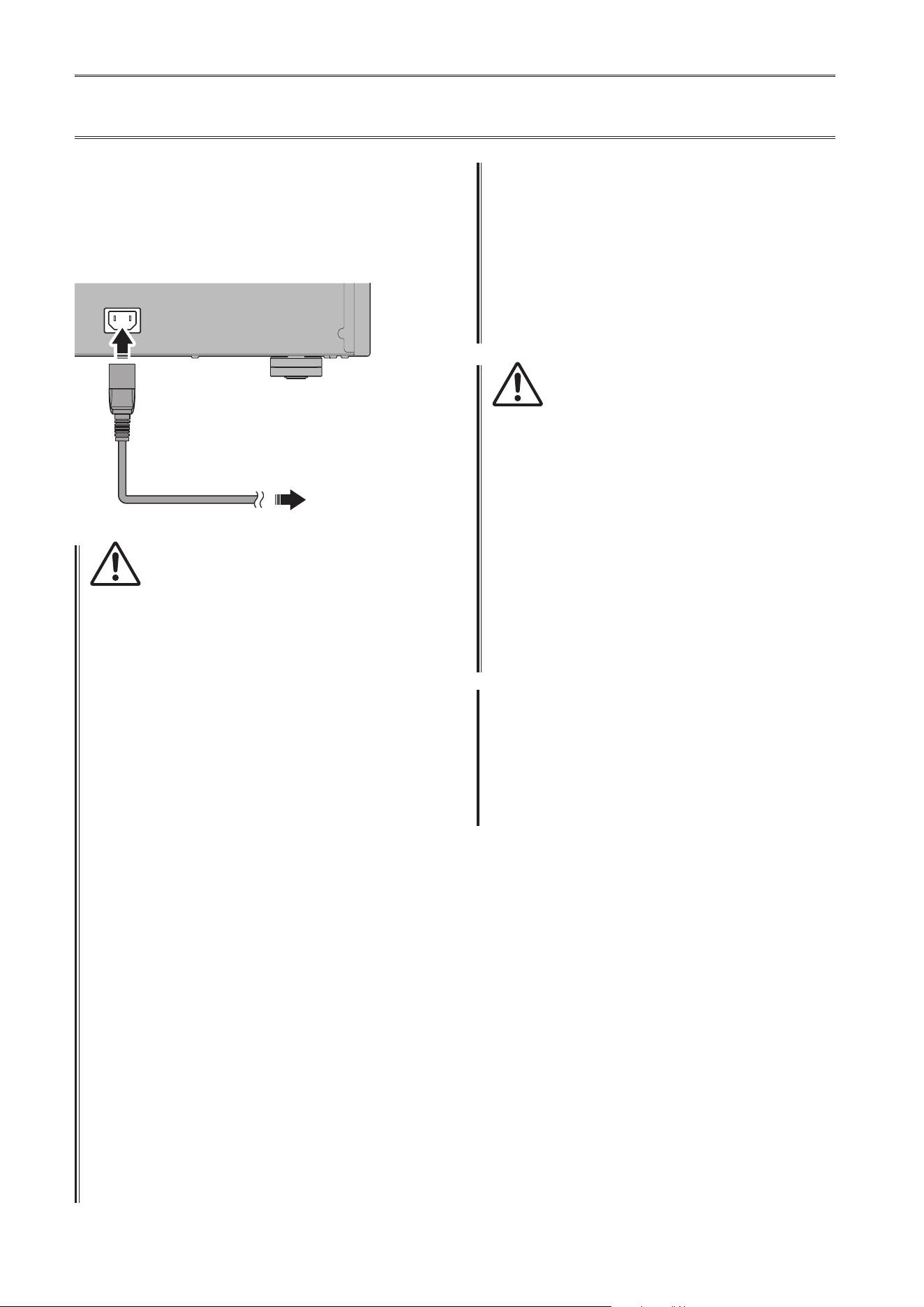
Connecting the power cord
After all connections are complete, make sure that the
STANDBY/ON/OFF (Power) switch is turned off, then
plug the power cord into the AC IN connector of the unit,
and then plug the power cord into the AC outlet.
AC IN
To AC outlet
M-5000
Rear panel
Supplied
power cord
WARNING
• If you notice any of the following abnormal conditions,
turn o the power to the unit immediately, and
disconnect the power plug from the AC outlet.
- The power cord or plug is damaged.
- The unit is emitting odor, strange noise, or smoke.
- Liquid has been spilled or objects have fallen into the
unit.
- Sound is muted all of a sudden during the operation.
- The unit is cracked or damaged.
Otherwise, continued use of the unit might lead to
electric shock, re, or malfunction. Contact your nearest
Yamaha dealer or service center for check-up or repair.
• Do not touch the power cord or plug during lightning
storms. Otherwise, an electric shock might be caused.
• Be sure to use a power outlet with the power voltage
labeled on the unit. If the unit is plugged into an outlet
of an inappropriate voltage, re, electric shock, or
malfunction might be caused.
• Use only the supplied power cord. Do not use the
supplied power cord for other devices.
Otherwise, re, burning, or malfunction might be caused.
• Plug the unit into an AC outlet that is clearly visible and
easily reached, so that you can unplug the unit easily and
quickly from the AC outlet in case of emergency.
Even when the power switch is turned o, a minimal
amount of electric current is still owing to the unit,
unless you unplug the unit from the AC outlet.
• If a lightning storm is approaching, turn o the power
to the unit immediately, and disconnect the power plug
from the AC outlet.
Otherwise, re or malfunction might be caused.
• If you plan not to use the unit for an extended period
of time, be sure to unplug the power cord from the AC
outlet.
Otherwise, re or malfunction might be caused.
CAUTION
• Do not use an AC outlet that is so loose that the plug
does not stay rmly in place. Otherwise, re, electric
shock, or burning might be caused.
• When disconnecting the power cord from the AC outlet,
grasp the plug; do not pull the cord. Otherwise, the
power cord may be damaged, causing an electric shock
or re.
• Insert the power plug into the AC outlet all the way
rmly. If the plug is not inserted completely, use of the
unit might cause an electric shock. Or, dust might build
up on the plug, causing re or burning.
NOTICE
If you plan not to use the unit for an extended period of
time, be sure to unplug the power cord from the AC outlet.
Even when the STANDBY/ON/OFF (Power) switch is turned
o (the power indicator is dark), a minimal amount of
electric current is still owing to the unit.

25
English
Reference Materials

26
General specications
Driven in monaural,
LINE to SPEAKERS, 200 W/8Ω .......... 0.05%
Driven in monaural,
BAL to SPEAKERS, 200 W/8Ω ...........0.05%
Channel separation (Input 1.0 kΩ terminated)
1 kHz/10 kHz ................. ≥90 dB/ ≥70 dB
Signal to noise ratio (IHF-A network, input 1.0 kΩ
shorted, reference level 200 W/4Ω)
.................................... 110 dB
Residual noise (IHF-A network)
BAL .............................. 40 μVrms
LINE ............................. 50 μVrms
Meter accuracy
...................................Class 2.5
Power supply
[Models for U.S.A. and Canada] .. AC 120 V, 60 Hz
[Model for China] ............. AC 220 V, 50 Hz
[Model for Korea] ............. AC 220 V, 60 Hz
[Model for Australia] ....... AC 230–240 V, 50 Hz
[Models for U.K. and Europe] ... AC 230 V, 50 Hz
[Model for Asia] .....AC 220–240 V, 50 Hz/60 Hz
[Models for Central and South America,
and Taiwan] .................. AC 110 V, 60 Hz
Power consumption
.....................................400 W
Standby power consumption
O mode ............................. 0.1 W
Standby mode ......................... 0.2 W
Maximum power consumption (1 kHz, 4Ω 10% THD)
[Models for Central and South America,
and Taiwan] ...........................800 W
Dimensions (W x H x D)
......................... 435 × 180 × 464 mm
(17-1/8" × 7-1/8" × 18-1/4")
Weight
............................ 26.9 kg (59.3 lbs)
* The contents of this manual apply to the latest
specications as of the publishing date. To obtain
the latest manual, access the Yamaha website then
download the manual le.
Rated output power (20 Hz to 20 kHz, 0.07% THD)
2-channel driven, 8Ω ............ 100 W + 100 W
2-channel driven, 4Ω ............ 200 W + 200 W
Driven in monaural, 8Ω ..................400 W
Dynamic power
8Ω .......................... 125 W + 125 W
6Ω .......................... 170 W + 170 W
4Ω .......................... 250 W + 250 W
2Ω .......................... 500 W + 500 W
Maximum output power (1 kHz, 0.7% THD)
[Models for U.K. and Europe]
4Ω .......................... 220 W + 220 W
IEC output power (1 kHz, 0.02% THD)
[Models for U.K. and Europe]
8Ω .......................... 125 W + 125 W
Maximum eective output power
(JEITA, 1 kHz, 10% THD)
[Models for China, Korea, U.K., Asia, Central and
South America, and Taiwan]
8Ω .......................... 135 W + 135 W
4Ω .......................... 270 W + 270 W
Power bandwidth (MAIN L/R, 0.1% THD, 45 W)
8Ω ..........................10 Hz to 50 kHz
Damping factor (1 kHz)
8Ω ................................... ≥300
Input sensitivity/input impedance (1 kHz, 100 W/8Ω)
BAL ......................... 2.0 Vrms/47 kΩ
LINE ........................ 1.0 Vrms/47 kΩ
Maximum input signal voltage (1 kHz, 0.5% THD)
BAL ..............................2.20 Vrms
LINE .............................1.10 Vrms
Frequency response
5 Hz to 100 kHz .................... +0/−3 dB
20 Hz to 20 kHz ...................+0/−0.3 dB
Total harmonic distortion plus noise (20 Hz to 20 kHz)
2-channel driven,
LINE to SPEAKERS, 50 W/8Ω .......... 0.035%
2-channel driven,
BAL to SPEAKERS, 50 W/8Ω ...........0.035%
27
English
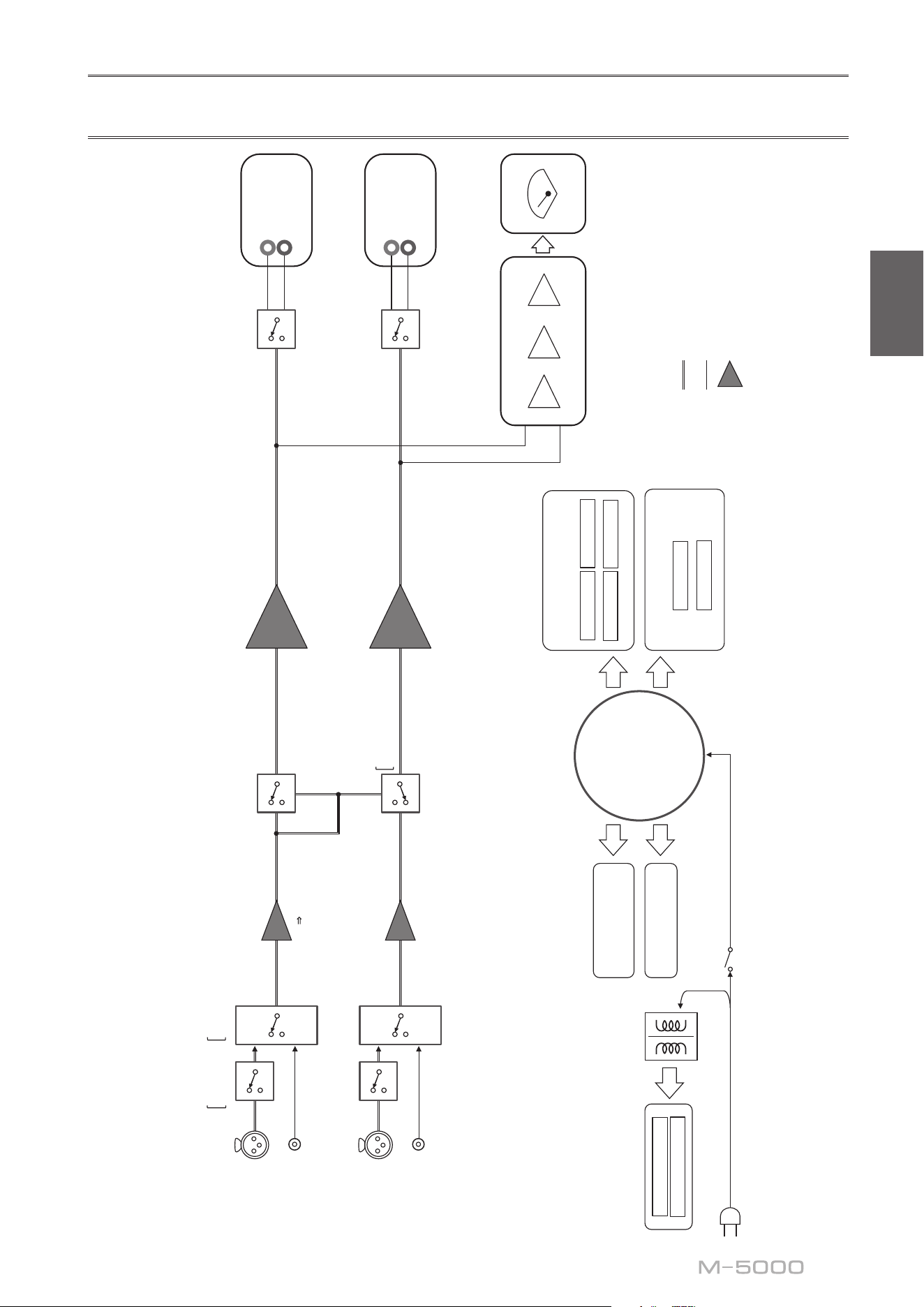
Block diagram
BAL
L
(DUAL MONO)
(BRIDGE)
LINE
L
(DUAL MONO)
(BRIDGE)
BAL
R
LINE
R
POWER AMP
BALANCE
UNBALANCE
FLOATING BALANCE AMPLIFIER
MODE
PHASE
NORMAL
INVERTED
UNBAL
BALANCE
CONVERTER
FLOATING INDEPENDENT
POWER SUPPLY
CONSTANT CURRENT
POWER SUPPLY
FOR AUDIO
SUB TRANSFORMER
L CH +
L CH -
R CH +
R CH -
POWER AMP PRE STAGE
L +/-
R +/-
CPU/LOGIC
STANDBY POWER
POWER SUPPLY
FOR CONTROL
NORMAL
DUAL MONO/BRIDGE
TOROIDAL
TRANSFORMER
PEAK/VU
LOG AMP
DRIVER
METER CIRCUIT
METER
SPEAKERS
L CH
+
−
SPEAKERS
R CH
+
−
INPUT
BAL
LINE
28
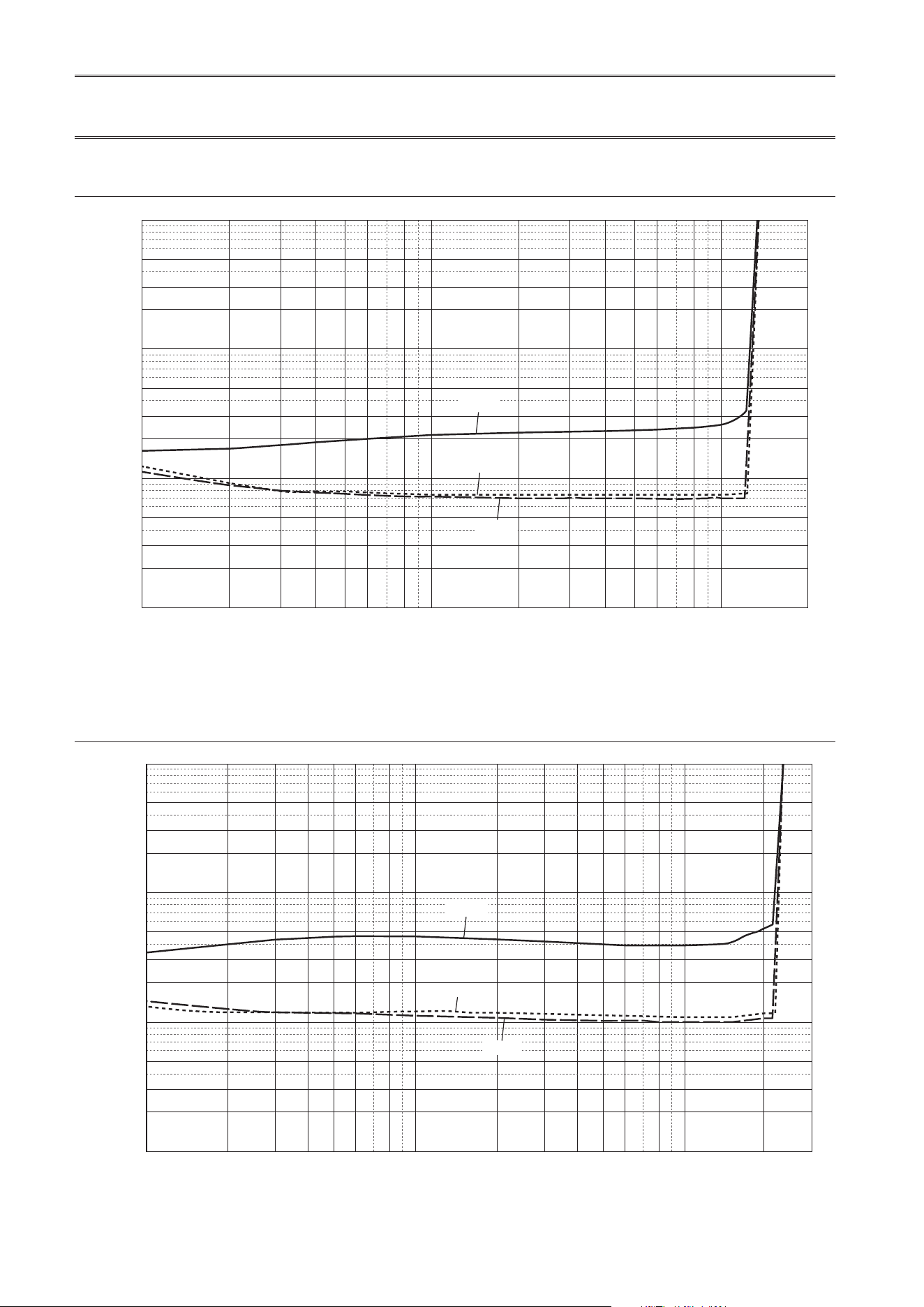
Audio characteristics
Total harmonic distortion (8Ω)
0.5
0.3
1
0.2
0.1
0.05
0.03
0.02
0.01
0.005
0.003
0.002
0.001
123456 810
200
20 30 40 50 60 80 100
THD + N Ratio (%)
Output (W)
20 kHz
20 Hz
1 kHz
Total harmonic distortion (4Ω)
0.5
0.3
1
0.2
0.1
0.05
0.03
0.02
0.01
0.005
0.003
0.002
0.001
1 23456810 200
300
20 30 40 50 60 80 100
THD + N Ratio (%)
Output (W)
20 kHz
20 Hz
1 kHz
29
English
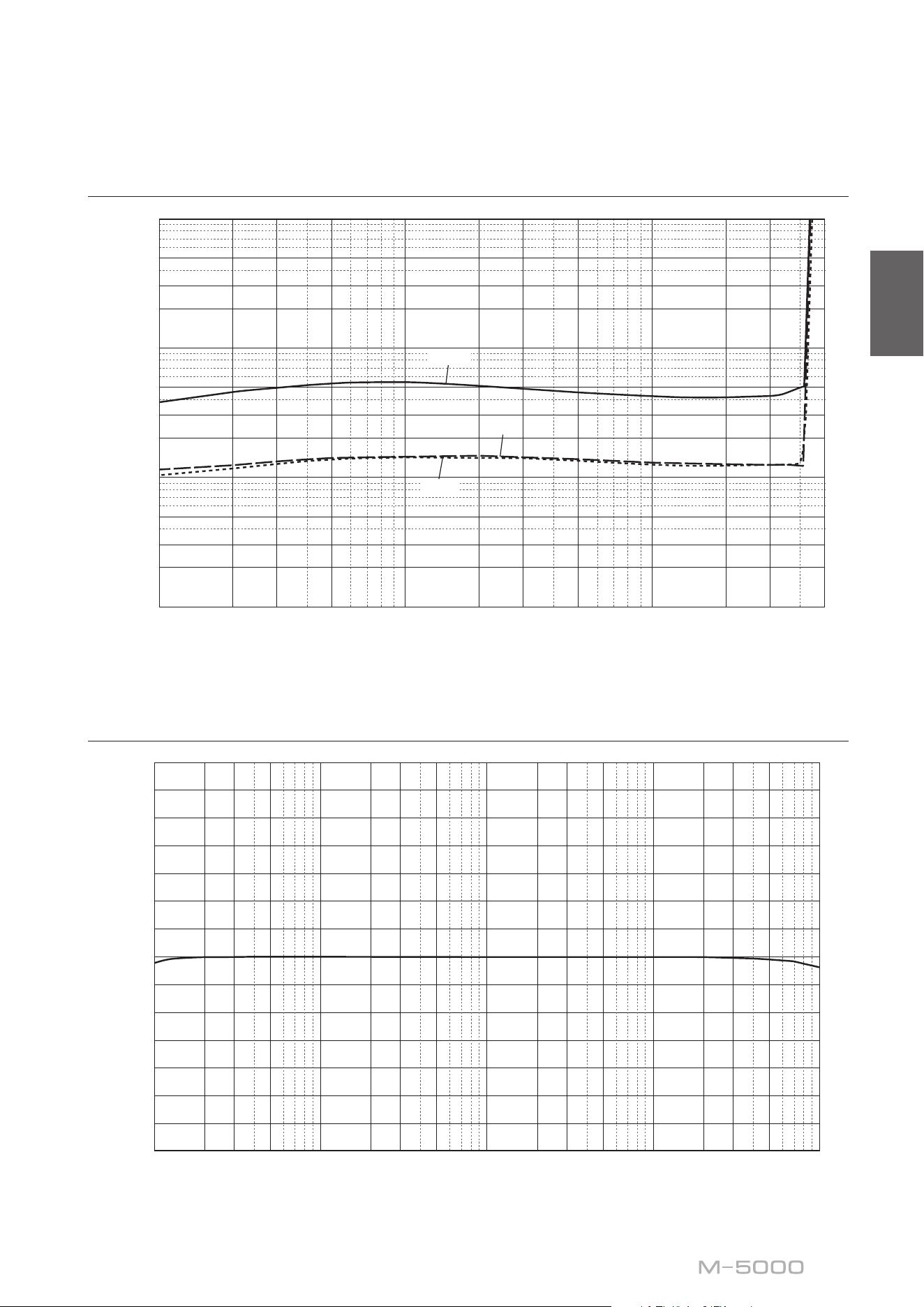
Total harmonic distortion (monaural 8Ω)
0.5
0.3
1
0.2
0.1
0.05
0.03
0.02
0.01
0.005
0.003
0.002
0.001
1 23 5 10 200 300
500
20 30 50 100
THD + N Ratio (%)
Output (W)
20 kHz
20 Hz
1 kHz
Frequency response
14
12
10
8
6
4
2
0
–2
–4
–6
–8
–10
–12
–14
10 20 30 50 100 200 300 20k500 1k 2k 3k 30k 50k 100
k
5k 10k
Response (dB)
Frequency (Hz)

30
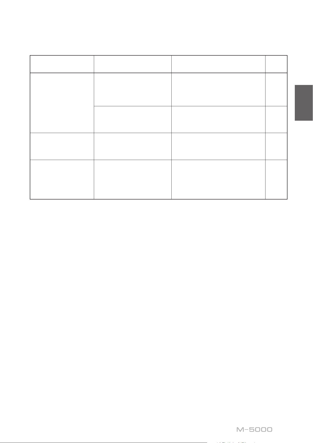
Troubleshooting
Refer to the table below if this unit does not function properly. If the instructions below do not help, or if the problem
you are experiencing is not listed below, turn off the unit, disconnect the power cord, and contact the nearest authorized
Yamaha dealer or service center.
Problem Cause Remedy
See
page
Power does not turn
on.
The power cord is not connected
to the AC IN connector on the
rear panel or is not plugged into
an AC outlet.
Connect the power cord firmly. 24
The protection circuitry has
been activated because of a
short circuit, etc.
Make sure that the speaker wires are
not touching each other or shorting out
against the rear panel of the unit, and
then turn on the power to the unit.
16
The unit has been exposed to
a strong external electric shock
(such as lightning or strong
static electricity).
Turn off the unit, disconnect the power
cord from the AC outlet, wait for about
30 seconds, and then plug the unit in
again.
24
The STANDBY/ON
indicator on the front
panel ashes.
The protection circuitry has
been activated because of a
short circuit, etc.
Make sure that the speaker wires are
not touching each other or shorting out
against the rear panel of the unit, and
then turn on the power to the unit.
16
There is a problem with the
internal circuitries of this unit.
Disconnect the power cord from the
AC outlet and contact the nearest
authorized Yamaha dealer or service
center.
24
The unit is turned on
but no sound is heard.
The protection circuitry has
been activated because of a
short circuit, etc.
Make sure that the speaker wires are
not touching each other or shorting out
against the rear panel of the unit, and
then turn on the power to the unit.
16
The SPEAKERS selector is set to
OFF.
Set the SPEAKERS selector to the
appropriate position.
6
The speaker cables are not
connected properly.
Make sure that the speaker cables are
connected properly.
16
The INPUT selector setting does
not match the connected input
source.
Select an appropriate input source with
the INPUT selector on the front panel.
12
31
English
Problem Cause Remedy
See
page
The sound is suddenly
muted.
The protection circuitry has
been activated because of a
short circuit, etc.
Make sure that the speaker wires are
not touching each other or shorting out
against the rear panel of the unit, and
then turn on the power to the unit.
16
The speakers are not connected
properly.
Make sure that the speakers are
connected properly. If the problem
persists, the cables might be defective.
16
There is a lack of bass
and no ambience.
The + and − wires are connected
in reverse at the amplifier or the
speakers.
Connect the speaker wires to the correct
+ and − polarity.
15
A “humming” noise is
heard.
Both balanced and unbalanced
cables are being used
simultaneously between two
components.
Do not use both balanced and
unbalanced cables simultaneously
between two components. Doing so
would create a ground loop that could
generate static and noise.
12

32
Index
A
AUTO POWER STANDBY switch ............ 9
B
Balanced connection ....................... 10
Balanced input jack ........................ 12
BAL input jack ........................... 12
Banana plug cable ......................... 17
Bi-amp connection ......................... 20
Bi-wiring connection ....................... 18
Bridge connection ......................... 22
C
Connecting a preamplier ................... 12
Connecting the speaker cables ................ 16
Connecting the speakers .................... 14
F
Feet ..................................... 9
I
INPUT selector ........................... 12
L
LINE input jack ........................... 12
M
METER selector ........................... 7
MODE selector ............................ 9
P
PHASE selector ........................... 10
Power cord ............................... 24
Power indicator ............................ 6
Power switch .............................. 6
S
SERVICE jack ............................. 9
SPEAKERS selector ........................ 6
STANDBY/ON/OFF indicator ................ 6
STANDBY/ON/OFF switch .................. 6
T
Trigger connection ......................... 13
TRIGGER jack ........................... 13
Turning the power on ........................ 6
U
Unbalanced connection ..................... 10
Y
Y-shaped lug cable ......................... 17

33
English

34
Nous vous remercions et vous félicitons d’avoir choisi ce produit Yamaha.
¡
Cet amplicateur de puissance vous permet de bénécier chez vous d’un son stéréo de haute qualité.
¡
Ce Mode d’emploi décrit les fonctions de l’appareil et les procédures de connexion.
¡
An de garantir une utilisation correcte et sûre du produit, nous vous conseillons de lire ce Mode
d’emploi ainsi que la Brochure sur la sécurité (document séparé).
Conservez ce Mode d’emploi dans un endroit sûr et facile d’accès en vue de références futures.
Vous pouvez télécharger la version électronique (PDF) de ce Mode d’emploi sur le site Internet Yamaha ci-
dessous.
https://download.yamaha.com/
Fonctions
¡
Transmission à symétrie ottante à tous les étages
¡
Sélecteurs à levier hautement rigides
¡
Construction stable à masse mécanique réduisant radicalement l’effet des vibrations externes
¡
Conception symétrique gauche-droite
¡
Alimentation de haute capacité disposant de quatre circuits distincts et gros condensateurs de 33000 μF
Í
4
¡
Pieds à crampon en laiton de conception neuve
¡
Puissance massive de 400 W/8Ω en mono
À propos de ce manuel
¡
Les illustrations dans ce manuel sont uniquement fournies à des ns explicatives.
¡
Les noms de sociétés et de produits gurant dans ce manuel sont des marques commerciales ou des
marques déposées de leurs détenteurs respectifs.
¡
«
AVERTISSEMENT
» décrit des précautions à suivre impérativement pour éviter les risques
de blessures graves, voire de décès.
¡
«
ATTENTION
» décrit des précautions à suivre impérativement pour éviter les risques de
blessures.
¡
«
AVIS
» décrit des précautions à suivre impérativement pour éviter les risques de dysfonctionnement/
d’endommagement de ce produit, ainsi que l’endommagement des données.
¡
«
Note
» fournit des informations complémentaires sur le produit.
¡
Avant la première utilisation de ce produit, veuillez lire le document annexe « Brochure sur la sécurité ».
Français

35
Français
Sommaire
Fonctions 34
À propos de ce manuel 34
Accessoires fournis 36
Entretien 36
Panneaux latéraux de ni miroir. . . . . . . . . . . . . . . . . . . . . . 36
Autres surfaces . . . . . . . . . . . . . . . . . . . . . . . . . . . . . . . . 36
Commandes et fonctions
Panneau avant 38
Panneau arrière 40
Connexions symétriques et asymétriques . . . . . . . . . . . . . . . 42
Raccordements
Connexion d’un préamplicateur 44
Connexions Trigger 45
Connexions conventionnelles d’enceintes 46
Connexion des câbles d’enceinte 48
Connexion via des câbles d’enceinte conventionnels . . . . . . . . 48
Connexion via des câbles avec ches bananes . . . . . . . . . . . . 49
Connexion via des câbles à cosse en Y . . . . . . . . . . . . . . . . . . 49
Connexions bilaires 50
Connexions biampliées 52
Connexion pontée 54
Raccordement du cordon d’alimentation 56
Références techniques
Caractéristiques générales 58
Schéma fonctionnel 59
Caractéristiques sonores 60
Distorsion harmonique totale (8Ω) . . . . . . . . . . . . . . . . . . . . 60
Distorsion harmonique totale (4Ω) . . . . . . . . . . . . . . . . . . . . 60
Distorsion harmonique totale (mono 8Ω). . . . . . . . . . . . . . . . 61
Réponse en fréquence . . . . . . . . . . . . . . . . . . . . . . . . . . . . 61
Guide de dépannage 62
Index 64

36
Accessoires fournis
Veuillez vous assurer que l’emballage contient tous les éléments suivants.
• Cordon d’alimentation
• Câble système
• Mode d’emploi (ce document)
• Brochure sur la Sécurité (document séparé)
AVERTISSEMENT
N’utilisez pas le cordon d’alimentation fourni avec d’autres appareils.
Entretien
Pour garantir une longévité optimale de ce produit, nous vous conseillons d’en prendre soin et de l’inspecter
régulièrement.
AVERTISSEMENT
• Vériez régulièrement le cordon d’alimentation pour vous assurer qu’il n’est pas empoussiéré. Éliminez toute poussière du
cordon. Un cordon d’alimentation empoussiéré peut causer un incendie ou un choc électrique.
• N’utilisez ni aérosol ni vaporisateur de gaz inammable pour le nettoyage ou la lubrication. L’accumulation de gaz
inammable à l’intérieur de l’appareil pourrait causer une explosion ou un incendie.
AVIS
• Nettoyez la surface de l’appareil avec un chion doux et sec. L’emploi de produits de nettoyage tels que du benzène, du du
diluant ou des chions imprégnés de produits chimiques pourrait causer la décoloration ou l’endommagement de la surface
de l’appareil. Si la surface de l’appareil est très encrassée, frottez-la avec un chion imbibé de détergent (dilué dans de l’eau) et
préalablement soigneusement essoré.
• Ne frottez pas avec force la zone du logo Yamaha, car celui-ci risquerait de se détacher ou des bres du chion pourraient
s’accrocher à sa surface.
Panneaux latéraux de ni miroir
Nous vous conseillons d’utiliser un chiffon de nettoyage tel que ceux pour piano. Si la surface est fort encrassée, utilisez
un chiffon doux imbibé d’eau et correctement essoré.
Autres surfaces
Nettoyez toutes les autres surfaces de l’appareil avec un chiffon
doux et sec. Si la surface de l’appareil est très encrassée,
frottez-la avec un chiffon imbibé de détergent dilué dans de
l’eau et préalablement soigneusement essoré.
Panneaux
latéraux de ni
miroir

37
Français
Commandes et fonctions
Cette section décrit les noms et fonctions des éléments équipant
les panneaux avant et arrière de l’appareil.
38
Panneau avant
A.
Interrupteur/témoin STANDBY/ON/OFF
(alimentation)
Permet de mettre l’appareil sous tension et hors tension.
STANDBY/ON
: Met l’appareil sous tension.
OFF
: Met l’appareil hors tension.
Statut d’alimentation Témoin
Mode sous tension Fortement allumé
Mode veille Faiblement allumé
Mode hors tension Éteint
L’appareil entre en mode veille dans un des cas suivants :
• Quand l’appareil est sous tension mais n’est pas
manipulé pendant huit heures lorsque la fonction de
mise en veille automatique est active, ou
• quand vous mettez hors tension l’appareil raccordé à la
prise TRIGGER IN de cet appareil.
Pour plus d’informations, voyez«
G
Commutateur
AUTO POWER STANDBY » dans la section « Panneau
arrière » (page 41) et « Connexions Trigger »
(page 45).
Note
Après la mise sous tension de l’appareil, celui-ci met
quelques secondes à restituer le son.
AVIS
Si vous ne comptez pas utiliser l’appareil pendant une
période prolongée, débranchez son cordon d’alimentation
de la prise de courant. Même quand l’appareil est mis
hors tension avec son commutateur STANDBY/ON/OFF
(alimentation), une faible quantité de courant électrique
transite toujours dans l’appareil.
B.
Sélecteur SPEAKERS
Active ou désactive les deux paires d’enceintes
raccordées aux bornes SPEAKERS A et B sur le panneau
arrière.
OFF
: Les deux paires d’enceintes sont désactivées.
A
: La paire d’enceintes connectée aux bornes A est
activée.
B
: La paire d’enceintes connectée aux bornes B est
activée.
A+B/BI-WIRING
: Les deux paires d’enceintes sont
activées.
A MPLIFIER
POWER
NATURAL SOUND
SPEAKERS
OFF
A
B
A
+
B
WIRING
BI
METER
OFF
PEAK
INPUT
LINE
BAL
VU
DIMMER
39
Français
AVIS
Veillez à ce que l’impédance de chaque enceinte
corresponde à la conguration du système. Pour plus
d’informations, voyez «Connexions conventionnelles
d’enceintes» (page46), «Connexions bilaires»
(page50), «Connexions biampliées» (page52) et
«Connexion pontée» (page54).
C.
Indicateur de niveau (LEFT/RIGHT)
Indique le niveau de sortie audio des voies gauche et
droite.
D.
Sélecteur METER
Commute l’indicateur de niveau sur OFF, PEAK ou VU.
DIMMER
: Règle la luminosité de l’indicateur de niveau.
La luminosité change lentement du niveau maximum au
niveau minimum (éteint). Quand vous sélectionnez le
type d’indicateur de niveau avec le sélecteur METER, le
degré de luminosité atteint au moment de la sélection est
adopté.
OFF
: Désactive l’indicateur de niveau et son
illumination.
PEAK
: Active l’indicateur de niveau de type PEAK-
mètre. Le PEAK-mètre ou indicateur du niveau de crête
indique les pics de niveau instantanés du signal audio.
VU
: Active l’indicateur de niveau de type VU-mètre
(« VU » signie « unité de volume »). Le VU-mètre
afche une valeur de sortie audio effective correspondant
à la perception humaine du volume.
E.
Sélecteur INPUT
Permet de sélectionner les prises d’entrée pour la lecture
d’une source audio.
LINE
: Reproduit le signal de la source audio connectée
aux prises LINE.
BAL
: Reproduit le signal de la source audio connectée
aux prises BAL.
A MPLIFIER
POWER
NATURAL SOUND
SPEAKERS
OFF
A
B
A
+
B
WIRING
BI
METER
OFF
PEAK
INPUT
LINE
BAL
VU
DIMMER

40
Note
Pour des informations sur la procédure de connexion, voyez
«Raccordements» (page43).
A.
Bornes SPEAKERS R CH
B.
Bornes SPEAKERS L CH
Branchez les enceintes à ces bornes avec les câbles
d’enceinte fournis. Pour des informations sur la procédure
de connexion, voyez « Raccordements » (page 43).
C.
Prises d’entrée BAL
Il s’agit de prises d’entrée symétriques de type XLR.
Branchez votre préamplicateur à ces prises. Réglez
le sélecteur PHASE sur la position appropriée pour le
préamplicateur raccordé.
D.
Sélecteur PHASE
Permet de régler l’affectation (polarité) de la broche
point CHAUD aux prises d’entrée BAL en fonction du
préamplicateur connecté. Pour plus d’informations,
voyez « Connexions symétriques et asymétriques »
(page 42).
NORMAL
: La broche 2 correspond au point CHAUD.
INVERTED
: La broche 3 correspond au point CHAUD.
Reportez-vous au manuel de l’appareil connecté pour
vérier l’affectation de la broche point CHAUD sur les
prises de sortie symétriques de l’appareil en question.
E.
Prises d’entrée LINE
Il s’agit de prises d’entrée asymétriques de type RCA .
Branchez votre préamplicateur à ces prises.
Panneau arrière
B
B
41
Français
F.
Sélecteur MODE
Permet d’alterner entre le mode de fonctionnement mono
et stéréo de l’amplicateur. Pour plus d’informations,
voyez « Connexions conventionnelles d’enceintes »
(page 46), « Connexions bilaires » (page 50),
« Connexions biampliées » (page 52) et « Connexion
pontée » (page 54).
NORMAL
: L’appareil fonctionne comme un amplicateur
stéréo. Il s’agit du réglage normal.
DUAL MONO/BRIDGE
: L’appareil fonctionne comme un
amplicateur mono. Choisissez cette position pour des
connexions biampliées ou pontées (« bridgées »).
G.
Commutateur AUTO POWER STANDBY
ON
: L’appareil entre automatiquement en mode veille
s’il est sous tension mais n’est pas manipulé pendant
huit heures. Cette fonction est désactivée quand le câble
système est branché à la prise TRIGGER IN.
OFF
: L’appareil n’entre pas automatiquement en mode
veille.
H.
Prise TRIGGER IN
I.
Prise TRIGGER OUT
Cette prise permet de brancher un appareil compatible
avec la fonction de déclenchement (Trigger) an
de commander la mise sous tension et hors tension
de cet appareil depuis l’appareil connecté. Pour
plus d’informations, voyez « Connexions Trigger »
(page 45).
J.
Prise SERVICE
Cette prise est utilisée pour tester l’appareil.
K.
Prise AC IN
Branchez le cordon d’alimentation fourni à cette prise.
Pour plus d’informations, voyez « Raccordement du
cordon d’alimentation » (page 56).
L.
Pieds
Si l’appareil n’est pas stable, ajustez sa hauteur en
tournant ses pieds.
B
B
42
Connexions symétriques et
asymétriques
Cet appareil comporte des prises d’entrée symétriques
(BAL) et asymétriques (LINE).
AVIS
N’utilisez pas simultanément une connexion symétrique
et une connexion asymétrique entre deux appareils. Cela
génère une boucle de masse susceptible de causer des
interférences et du bruit.
Connexion symétrique
Une connexion symétrique offre un avantage considérable
contre le bruit externe. Pour effectuer une connexion
symétrique, utilisez un câble à ches XLR mâles. Pour
brancher un câble, alignez les broches de la che avec
les orices de la prise, puis insérez la che dans la prise
jusqu’à ce que vous entendiez un déclic. Pour débrancher
le câble, appuyez sur le levier de la prise BAL tout en
tirant la che du câble XLR hors de la prise.
Broche 2
Broche 3
Broche 1
Dans le cas d’une connexion symétrique, il est impératif
de régler correctement la polarité. Pour régler la polarité,
utilisez le sélecteur PHASE sur le panneau arrière.
B
B
B
B
PHASE
NORMAL
INVERTED
Quand le sélecteur PHASE est sur la position NORMAL,
la broche 2 correspond au point CHAUD.
1 : masse (terre)
3 : point froid
2 : point chaud
Levier
Quand le sélecteur PHASE est sur la position
INVERTED, la broche 3 correspond au point CHAUD.
1 : masse (terre)
3 : point chaud
2 : point froid
Levier
Note
Sélectionnez la position NORMAL (broche 2=point CHAUD)
pour un lecteur ou préamplicateur Yamaha.
Connexion asymétrique
Pour une connexion asymétrique, utilisez des câbles
avec ches RCA. Ces câbles ne transmettent pas les
informations de phase.

43
Français
Raccordements
Cette section décrit la connexion de l’appareil à un
préamplicateur et des enceintes.
ATTENTION
Mettez tous les appareils hors tension avant d’eectuer toute connexion.
AVIS
Avant de brancher des appareils externes, lisez les manuels de ces appareils et suivez leurs consignes. Sinon, vous risquez un
dysfonctionnement de cet appareil ou des composants externes.
44
Connexion d’un préamplicateur
Branchez votre préamplicateur aux prises d’entrée de cet appareil. Pour cette connexion, utilisez des câbles XLR
symétriques ou RCA asymétriques.
Connexion symétrique
Connexion asymétrique
INPUT
LINE
BAL
B
B
B
B
M-5000
R
BAL
Préamplicateur
Câble XLR symétrique
INPUT
LINE
BAL
B
B
B
B
LINE 1
M-5000
R
Préamplicateur
Câble RCA
AVIS
Le niveau de volume de cet appareil est xe. Ne branchez
pas de composant ne comportant pas de réglage de
volume aux prises d’entrée de cet appareil. Le non-respect
de cette consigne pourrait causer la production d’un son
de niveau extrême causant un dysfonctionnement de
l’appareil ou un endommagement des enceintes.
Note
• Si le préamplicateur ore des connexions symétrique et
asymétrique, utilisez la connexion symétrique.
• N’utilisez pas simultanément une connexion symétrique
et une connexion asymétrique entre deux appareils. Cela
génère une boucle de masse susceptible de causer des
interférences et du bruit.
Panneau avant
Panneau avant
45
Français
Connexions Trigger
La fonction Trigger permet de commander la mise sous tension et hors tension de cet appareil depuis un composant Yamaha
connecté, tel qu’un préamplicateur ou récepteur AV.
Utilisez le câble système fourni pour effectuer les connexions illustrées ci-dessous.
Exemple (avec un seul M-5000)
B
B
B
B
M-5000
Préamplicateur, etc
Câble système
Exemple (avec deux M-5000)
B
B
B
B
B
B
B
B
M-5000M-5000
Préamplicateur, etc
Câble système
Câble système
Pour commander l’appareil depuis un autre composant
via la connexion Trigger, réglez le commutateur
STANDBY/ON/OFF (alimentation) sur STANDBY/ON.
Quand le composant connecté est mis sous tension, cet
appareil est automatiquement mis sous tension. Quand le
composant connecté est mis hors tension, cet appareil est
automatiquement mis hors tension.
Note
Si l’interrupteur d’alimentation de cet appareil est en
position OFF, la commande à distance de l’alimentation ne
fonctionnera pas.

46
Connexions conventionnelles d’enceintes
1
Mettez l’appareil et tous les composants
connectés hors tension
2
Réglez le sélecteur MODE du panneau
arrière sur NORMAL
3
Réglez le sélecteur SPEAKERS en face
avant sur A, B ou A+B BI-WIRING
L’illustration suivante montre le sélecteur en
position A.
4
Raccordez l’amplicateur de puissance aux
bornes «+» et «−» des enceintes
ATTENTION
Veillez à utiliser des enceintes de l’impédance gurant dans
le tableau ci-dessous.
Impédance des enceintes
Sélecteur SPEAKERS A B A+B
Connexion
conventionnelle/
connexion bilaire
4Ω ou plus 8Ω ou plus
Connexion biamplifiée 4Ω ou plus 8Ω ou plus
Connexion pontée 8Ω ou plus 16Ω ou plus*
* Sauf les modèles pour les États-Unis et le Canada
B
B
SPEAKERS
OFF
A
B
A
+
B
WIRING
BI
High
Low
High
Low
MODE: NORMAL
M-5000
Sélecteur MODE
Barre de court-circuit
Préamplicateur
Voie R
Voie R Voie L
Signal de la voie
R
Signal de la voie
L
Voie R
47
Français
ATTENTION
Avant de remettre le composant source sous tension,
réduisez d’abord son volume au minimum.
AVIS
• Faites en sorte que la partie dénudée d’un conducteur
du câble d’enceinte ne puisse pas venir en contact avec
la partie dénudée de l’autre conducteur, ni avec une
pièce métallique de cet appareil. Sinon, l’appareil et/ou
les enceintes risquent d’être endommagés.
• Ne raccordez pas de subwoofer amplié à cet appareil.
Branchez le subwoofer au préamplicateur.
B
B
SPEAKERS
OFF
A
B
A
+
B
WIRING
BI
High
Low
High
Low
MODE: NORMAL
M-5000
Sélecteur SPEAKERS
(panneau avant)
Barre de court-circuit
Voie L
Voie L
Note
• Toutes les connexions doivent être correctes: L (gauche)
à L, R (droite) à R, «+» à «+» et «−» à «−». Si les
connexions sont incorrectes, aucun son ne sera produit
pas les enceintes. En outre, si la polarité des connexions
d’enceinte est incorrecte, le son manquera de naturel et
de grave.
• Vu que cet amplicateur de puissance est à symétrie
ottante, il n’est pas possible d’eectuer les types de
connexions ci-dessous.
- Une connexion entre les deux bornes «+» (ou les
deux broches «−») des voies gauche et droite (g. 1).
- Une connexion de chaque borne «−» des voies
gauche et droite de l’appareil à la borne d’enceinte
de la voie opposée (connexion croisée, g. 2).
- Une connexion des bornes «−» des voies gauche/
droite (ou un contact accidentel de ces bornes)
avec une partie métallique sur la face arrière de cet
appareil.
+
–
+
–
L
R
+
–
+
–
L
R
+
–
+
–
L
R
+
–
+
–
L
R
Figure
1
Figure
2
48
Connexion des câbles d’enceinte
Connexion via des câbles
d’enceinte conventionnels
1
Enlevez environ 10mm de la gaine isolante
à l’extrémité de chaque câble d’enceinte
et torsadez les ls exposés du câble pour
éviter les courts-circuits
10mm
2
Dévissez chaque borne SPEAKERS et
insérez la portion dénudée du l dans
l’orice sur le côté de la borne
Diamètre de l’orice du l de
câble d’enceinte : 6,0 mm
3
Revissez la borne
ATTENTION
• Ne desserrez pas trop la borne. Sinon, la borne risque de
se détacher et de tomber, posant un risque d’ingestion
accidentelle pour les enfants en bas âge.
• Pour réduire le risque de choc électrique, ne touchez pas
les bornes SPEAKERS lorsque l’appareil est sous tension.
AVIS
Si les bornes SPEAKERS entrent en contact avec un rack
métallique, cela pourrait causer un court-circuit susceptible
d’endommager cet appareil. Si vous installez l’appareil dans
un rack, maintenez une distance susante pour éviter que
les bornes SPEAKERS ne touchent le rack.
49
Français
Connexion via des câbles avec
ches bananes
Serrez d’abord la borne puis insérez la che banane dans
l’orice de la borne.
Diamètre de l’orice pour
che banane : 5,5 mm
Connexion via des câbles à cosse
en Y
1
Dévissez la borne et insérez la cosse en Y
entre l’anneau et la base de la borne
Épaisseur du centre
de la borne : 5,0 mm
Faites glisser
Cosse en Y
2
Revissez la borne

50
Connexions bilaires
Pour effectuer une connexion bilaire, vous devez utiliser
des câbles indépendants pour connecter le tweeter et le
woofer de chaque enceinte bilaire à l’amplicateur. La
connexion via des câbles indépendants permet d’alléger
considérablement l’effet de la force électromotrice
produite par la bobine du woofer sur le circuit du tweeter,
réduisant ainsi les interférences entre le grave et l’aigu et
produisant un meilleur son.
Pour ce type de connexion, vous devez utiliser des
enceintes comportant deux jeux de bornes (quatre bornes
au total) permettant de diviser chaque enceinte en deux
sections (grave et médium/aigu).
1
Mettez l’appareil et tous les composants
connectés hors tension
2
Retirez les barres de court-circuit ou les
pontages des enceintes
Les ltres passe-bas (LPF) et passe-haut (HPF)
sont alors séparés.
B
B
High
Low
High
Low
MODE: NORMAL
M-5000
SPEAKERS
OFF
A
B
A
+
B
WIRING
BI
Sélecteur MODE
Retirez la barre de court-circuit
PréamplicateurVoie R
Voie R Voie L
Signal de la voie
R
Signal de la voie
L
Voie R
51
Français
3
Raccordez les enceintes à l’amplicateur
de puissance
Pour chaque voie, raccordez les câbles des bornes
médium/aigu aux prises SPEAKERS A de la voie
correspondante de l’amplicateur, et les câbles des
bornes grave aux bornes SPEAKERS B de la voie
correspondante de l’amplicateur.
4
Réglez le sélecteur MODE du panneau
arrière sur NORMAL
5
Réglez le sélecteur SPEAKERS en face
avant sur A+B BI-WIRING
ATTENTION
Veillez à utiliser des enceintes de l’impédance gurant dans
le tableau ci-dessous.
Impédance des enceintes
Sélecteur SPEAKERS A B A+B
Connexion
conventionnelle/
connexion bilaire
4Ω ou plus 8Ω ou plus
Connexion biamplifiée 4Ω ou plus 8Ω ou plus
Connexion pontée 8Ω ou plus 16Ω ou plus*
* Sauf les modèles pour les États-Unis et le Canada
ATTENTION
Avant de remettre le composant source sous tension,
réduisez d’abord son volume au minimum.
B
B
High
Low
High
Low
MODE: NORMAL
M-5000
SPEAKERS
OFF
A
B
A
+
B
WIRING
BI
Retirez la barre de court-circuit
Voie L
Voie L
Sélecteur SPEAKERS
(panneau avant)

52
Connexions biampliées
La conguration d’un système stéréo biamplié requiert
deux amplicateurs M-5000.
Le M-5000 comporte deux amplicateurs intégrés.
Chacun de ces amplicateurs est connecté au tweeter et
au woofer de l’enceinte de la voie en correspondante.
Pour ce type de connexion, vous devez utiliser des
enceintes comportant deux jeux de bornes (quatre
bornes au total) permettant de diviser chaque enceinte en
deux sections (grave et médium/aigu). Les connexions
biampliées permettent d’éviter que l’effet de la force
électromotrice produite par le woofer n’affecte le son, et
produisent une amélioration du son dans certains cas.
Branchez la source d’entrée aux bornes de la voie gauche
(L) sur les deux amplicateurs M-5000.
1
Mettez l’appareil et tous les composants
connectés hors tension
2
Retirez les barres de court-circuit ou les
pontages des enceintes
Les ltres passe-bas (LPF) et passe-haut (HPF)
sont alors séparés.
B
B
B
B
SPEAKERS
OFF
A
B
A
+
B
WIRING
BI
High
Low
High
Low
M-5000
M-5000
MODE: DUAL MONO/BRIDGE
SPEAKERS
OFF
A
B
A
+
B
WIRING
BI
MODE: DUAL MONO/BRIDGE
Sélecteur MODE
Retirez la barre de court-circuit
PréamplicateurVoie R
Voie R Voie L
Signal de la voie
R
Signal de la voie
L
Voie R
Sélecteur SPEAKERS
(panneau avant)
53
Français
3
Réglez le sélecteur MODE du panneau
arrière sur DUAL MONO/BRIDGE
4
Réglez le sélecteur SPEAKERS en face
avant sur A, B ou A+B BI-WIRING
L’illustration suivante montre le sélecteur en
position A.
5
Raccordez les enceintes à l’amplicateur
de puissance (cet appareil)
Pour chaque voie, raccordez les câbles des bornes
médium/aigu aux bornes A de la voie SPEAKERS
R CH de l’amplicateur, et les câbles des bornes
grave aux bornes A de la voie SPEAKERS L CH
de l’amplicateur.
ATTENTION
Veillez à utiliser des enceintes de l’impédance gurant dans
le tableau ci-dessous.
Impédance des enceintes
Sélecteur SPEAKERS A B A+B
Connexion
conventionnelle/
connexion bifilaire
4Ω ou plus 8Ω ou plus
Connexion biampliée
4Ω ou plus 8Ω ou plus
Connexion pontée 8Ω ou plus 16Ω ou plus*
* Sauf les modèles pour les États-Unis et le Canada
ATTENTION
Avant de remettre le composant source sous tension,
réduisez d’abord son volume au minimum.
B
B
B
B
SPEAKERS
OFF
A
B
A
+
B
WIRING
BI
High
Low
High
Low
M-5000
M-5000
MODE: DUAL MONO/BRIDGE
SPEAKERS
OFF
A
B
A
+
B
WIRING
BI
MODE: DUAL MONO/BRIDGE
Retirez la barre de court-circuit
Voie L
Sélecteur MODE
Voie L
Sélecteur SPEAKERS
(panneau avant)
54
Connexion pontée
En mode ponté, le M-5000 est utilisé comme
amplicateur mono. Pour obtenir un système stéréo, il
faut donc deux amplicateurs M-5000.
Sur chaque amplicateur, reliez la borne « + » de la
voie SPEAKERS L CH à la borne « − » de la voie
SPEAKERS R CH. Effectuez cette connexion avec
un câble composé du même matériau que les câbles
d’enceintes, en veillant à ce que sa longueur ne dépasse
pas 1,0 m et sa section 1,0 mm
2
. N’attachez pas les câbles
en faisceau.
Branchez la source d’entrée aux bornes de la voie gauche
(L) sur les deux amplicateurs M-5000.
AVIS
L’amplication étant double dans cette conguration,
veillez à régler le niveau de volume de manière appropriée
sur le préamplicateur connecté. Si vous utilisez un
préamplicateur Yamaha équipé d’un sélecteur GAIN,
réglez le niveau de volume avec ce sélecteur de sorte à
permettre l’utilisation normale des commandes de volume
sur les autres appareils.
1
Mettez l’appareil et tous les composants
connectés hors tension
2
Réglez le sélecteur MODE du panneau
arrière sur DUAL MONO/BRIDGE
B
B
B
B
MODE: DUAL MONO/BRIDGE
SPEAKERS
OFF
A
B
A
+
B
WIRING
BI
SPEAKERS
OFF
A
B
A
+
B
WIRING
BI
High
Low
High
Low
MODE: DUAL MONO/BRIDGE
M-5000
M-5000
Barre de court-circuit
Sélecteur MODE
PréamplicateurVoie R
Voie R Voie L
Signal de la voie
R
Signal de la voie
L
Voie R
Sélecteur SPEAKERS
(panneau avant)
55
Français
3
Réglez le sélecteur SPEAKERS en face
avant sur A, B ou A+B BI-WIRING
L’illustration suivante montre le sélecteur en
position A.
4
Sur chaque amplicateur, reliez la borne
«+» de la voie SPEAKERS L CH à la borne
«−» de la voie SPEAKERS R CH
5
Reliez la borne «+» de la voie SPEAKERS R
CH à la borne «+» de l’enceinte et la borne
«
−» de la voie SPEAKERS L CH à la borne
«
−» de l’enceinte
ATTENTION
Veillez à utiliser des enceintes de l’impédance gurant dans
le tableau ci-dessous.
Impédance des enceintes
Sélecteur SPEAKERS A B A+B
Connexion
conventionnelle/
connexion bifilaire
4Ω ou plus 8Ω ou plus
Connexion biamplifiée 4Ω ou plus 8Ω ou plus
Connexion pontée 8Ω ou plus 16Ω ou plus*
* Sauf les modèles pour les États-Unis et le Canada
ATTENTION
Avant de remettre le composant source sous tension,
réduisez d’abord son volume au minimum.
B
B
B
B
MODE: DUAL MONO/BRIDGE
SPEAKERS
OFF
A
B
A
+
B
WIRING
BI
SPEAKERS
OFF
A
B
A
+
B
WIRING
BI
High
Low
High
Low
MODE: DUAL MONO/BRIDGE
M-5000
M-5000
Barre de court-circuit
Sélecteur MODE
Voie L
Voie L
Sélecteur SPEAKERS
(panneau avant)
56
Raccordement du cordon d’alimentation
Quand toutes les connexions sont terminées, vériez que le
commutateur STANDBY/ON/OFF (alimentation) est sur
OFF, puis raccordez le cordon d’alimentation à la prise AC
IN de l’appareil et la che secteur du cordon à une prise de
courant.
AC IN
Vers une prise secteur
M-5000
Panneau arrière
Cordon
d’alimentation fourni
AVERTISSEMENT
• Si vous remarquez une des anomalies suivantes, mettez
immédiatement l’appareil hors tension et débranchez
son cordon d’alimentation de la prise de courant.
- Le cordon d’alimentation ou sa che est endommagé.
- L’appareil émet une odeur, un bruit anormal ou de la
fumée.
- Du liquide ou des objets ont pénétré à l’intérieur de
l’appareil.
- Le son est brusquement coupé pendant l’utilisation.
- Le châssis de l’appareil est ssuré ou endommagé.
Si vous continuez d’utiliser l’appareil quand il présente
un de ces symptômes, cela pourrait causer un choc
électrique, un incendie ou un dysfonctionnement.
Contactez le revendeur ou SAV Yamaha le plus proche
pour faire vérier ou réparer l’appareil.
• Ne touchez jamais le cordon d’alimentation ni sa
che durant un orage. Sinon, vous risqueriez d’être
électrocuté.
• Veillez à brancher l’appareil à une prise de courant
fournissant la tension correcte mentionnée sur l’appareil.
La connexion de l’appareil à une prise de courant de
tension inappropriée peut causer un incendie, un choc
électrique ou un dysfonctionnement.
• Utilisez uniquement le cordon d’alimentation fourni.
N’utilisez pas le cordon d’alimentation fourni avec
d’autres appareils.
Sinon, cela pourrait causer un incendie, des brûlures ou
un dysfonctionnement.
• Branchez l’appareil à une prise de courant visible et
facile d’accès, de sorte à pouvoir débrancher l’appareil
rapidement et facilement en cas d’urgence.
À moins que vous ne débranchiez l’appareil du secteur,
une faible quantité de courant électrique transite
toujours dans l’appareil quand il est hors tension.
• En cas de risque d’orage, mettez immédiatement
l’appareil hors tension et débranchez son cordon
d’alimentation de la prise de courant.
Sinon, cela pourrait causer un incendie ou un
dysfonctionnement.
• Si vous ne comptez pas utiliser l’appareil pendant
une période prolongée, débranchez son cordon
d’alimentation de la prise de courant.
Sinon, cela pourrait causer un incendie ou un
dysfonctionnement.
ATTENTION
• N’utilisez pas de prise de courant ne permettant pas de
brancher fermement la che du cordon d’alimentation.
Sinon, cela pourrait causer un incendie, un choc
électrique ou des brûlures.
• Saisissez toujours la che du cordon d’alimentation pour
le débrancher de la prise de courant ; ne tirez jamais sur
le cordon. Sinon, vous risquez d’endommager le cordon
d’alimentation, ce qui pourrait causer un choc électrique
ou un incendie.
• Insérez la che du cordon d’alimentation fermement et
jusqu’au bout dans la prise de courant. Si la che n’est
pas insérée à fond dans la prise de courant, l’utilisation
de l’appareil pourrait causer un choc électrique. En outre,
de la poussière pourrait s’accumuler sur la che et poser
un risque d’incendie ou de brûlures.
AVIS
Si vous ne comptez pas utiliser l’appareil pendant une
période prolongée, débranchez son cordon d’alimentation
de la prise de courant. Même quand l’appareil est mis
hors tension avec son commutateur STANDBY/ON/OFF
(alimentation), une faible quantité de courant électrique
transite toujours dans l’appareil.

57
Français
Références techniques

58
Caractéristiques générales
Excité en mono,
LINE vers SPEAKERS, 200 W/8Ω ........0,05%
Excité en mono,
BAL vers SPEAKERS, 200 W/8Ω .........0,05%
Séparation des voies (entrée terminée à 1,0 kΩ)
1 kHz/10 kHz ................. ≥90 dB/ ≥70 dB
Rapport signal/bruit (réseau IHF-A, entrée court-
circuitée à 1,0 kΩ, niveau de référence de 200 W/4Ω)
.................................... 110 dB
Bruit résiduel (réseau IHF-A)
BAL .............................. 40 μVrms
LINE ............................. 50 μVrms
Précision de l’indicateur de niveau
.................................. Classe 2.5
Alimentation
[Modèles pour les États-Unis et le Canada]
............................ 120 V CA, 60 Hz
[Modèle pour la Chine] ........ 220 V CA, 50 Hz
[Modèle pour la Corée] ........ 220 V CA, 60 Hz
[Modèle pour l’Australie] ... 230–240 V CA, 50 Hz
[Modèles pour le Royaume-Uni et l’Europe]
............................ 230 V CA, 50 Hz
[Modèle pour l’Asie]
.................. 220–240 V CA, 50 Hz/60 Hz
[Modèles pour l’Amérique Centrale,
l’Amérique du Sud et Taïwan] ... 110 V CA, 60 Hz
Consommation
.....................................400 W
Consommation en veille
Mode hors tension ..................... 0,1 W
Mode veille ........................... 0,2 W
Consommation maximale (1 kHz, 4Ω, DHT 10%)
[Modèles pour l’Amérique Centrale,
l’Amérique du Sud et Taïwan] ............800 W
Dimensions (L × H × P)
......................... 435 × 180 × 464 mm
Poids
.................................... 26,9 kg
* Le contenu de ce mode d’emploi s’applique aux
dernières caractéristiques techniques connues à la date
de publication du manuel. Pour obtenir la version la
plus récente du manuel, accédez au site Web de Yamaha
puis téléchargez le chier du manuel concerné.
Puissance de sortie nominale
(20 Hz à 20 kHz, DHT 0,07%)
2 voies excitées, 8Ω ............. 100 W + 100 W
2 voies excitées, 4Ω ............. 200 W + 200 W
Excité en mono, 8Ω .....................400 W
Puissance dynamique
8Ω .......................... 125 W + 125 W
6Ω .......................... 170 W + 170 W
4Ω .......................... 250 W + 250 W
2Ω .......................... 500 W + 500 W
Puissance de sortie maximale (1 kHz, 0,7% DHT)
[Modèles pour le Royaume-Uni et l’Europe]
4Ω .......................... 220 W + 220 W
Puissance de sortie selon CEI (1 kHz, 0,02% DHT)
[Modèles pour le Royaume-Uni et l’Europe]
8Ω .......................... 125 W + 125 W
Puissance de sortie eective maximale
(JEITA, 1 kHz, DHT 10%)
[Modèles pour la Chine, la Corée, le Royaume-Uni,
l’Asie, l’Amérique Centrale, l’Amérique du Sud et
Taïwan]
8Ω .......................... 135 W + 135 W
4Ω .......................... 270 W + 270 W
Bande passante (MAIN L/R, DHT 0,1%, 45 W)
8Ω ...........................10 Hz à 50 kHz
Coecient d’amortissement (1 kHz)
8Ω ................................... ≥300
Sensibilité et impédance d’entrée (1 kHz, 100 W/8Ω)
BAL ......................... 2,0 Vrms/47 kΩ
LINE ........................ 1,0 Vrms/47 kΩ
Tension
maximale
du signal d’entrée (1 kHz, DHT 0,5%)
BAL ..............................2,20 Vrms
LINE .............................1,10 Vrms
Réponse en fréquence
5 Hz à 100 kHz ..................... +0/−3 dB
20 Hz à 20 kHz .................... +0/−0,3 dB
Distorsion harmonique totale plus bruit
(20 Hz à 20 kHz)
2 voies excitées,
LINE vers SPEAKERS, 50 W/8Ω ........0,035%
2 voies excitées,
BAL vers SPEAKERS, 50 W/8Ω .........0,035%
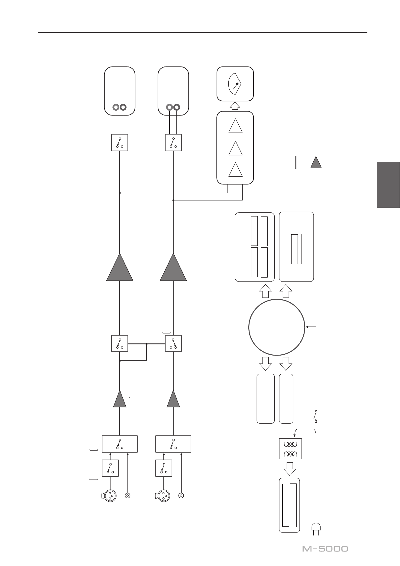
59
Français
Schéma fonctionnel
BAL
L
(DUAL MONO)
(BRIDGE)
LINE
L
(DUAL MONO)
(BRIDGE)
BAL
R
LINE
R
POWER AMP
BALANCE
UNBALANCE
FLOATING BALANCE AMPLIFIER
MODE
PHASE
NORMAL
INVERTED
UNBAL
BALANCE
CONVERTER
FLOATING INDEPENDENT
POWER SUPPLY
CONSTANT CURRENT
POWER SUPPLY
FOR AUDIO
SUB TRANSFORMER
L CH +
L CH -
R CH +
R CH -
POWER AMP PRE STAGE
L +/-
R +/-
CPU/LOGIC
STANDBY POWER
POWER SUPPLY
FOR CONTROL
NORMAL
DUAL MONO/BRIDGE
TOROIDAL
TRANSFORMER
PEAK/VU
LOG AMP
DRIVER
METER CIRCUIT
METER
SPEAKERS
L CH
+
−
SPEAKERS
R CH
+
−
INPUT
BAL
LINE

60
Caractéristiques sonores
Distorsion harmonique totale (8Ω)
0.5
0.3
1
0.2
0.1
0.05
0.03
0.02
0.01
0.005
0.003
0.002
0.001
123456 810
200
20 30 40 50 60 80 100
THD + N Ratio (%)
Output (W)
20 kHz
20 Hz
1 kHz
Distorsion harmonique totale (4Ω)
0.5
0.3
1
0.2
0.1
0.05
0.03
0.02
0.01
0.005
0.003
0.002
0.001
1 23456810 200
300
20 30 40 50 60 80 100
THD + N Ratio (%)
Output (W)
20 kHz
20 Hz
1 kHz
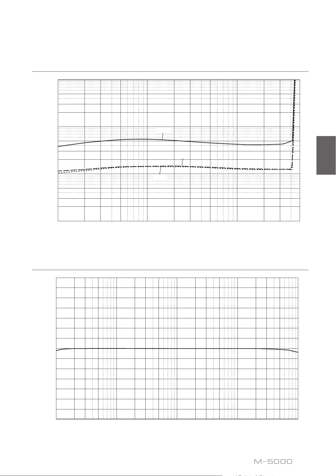
61
Français
Distorsion harmonique totale (mono 8Ω)
0.5
0.3
1
0.2
0.1
0.05
0.03
0.02
0.01
0.005
0.003
0.002
0.001
1 23 5 10 200 300
500
20 30 50 100
THD + N Ratio (%)
Output (W)
20 kHz
20 Hz
1 kHz
Réponse en fréquence
14
12
10
8
6
4
2
0
–2
–4
–6
–8
–10
–12
–14
10 20 30 50 100 200 300 20k500 1k 2k 3k 30k 50k 100
k
5k 10k
Response (dB)
Frequency (Hz)

62
Guide de dépannage
Reportez-vous au tableau suivant si l’appareil ne fonctionne pas comme il devrait. Si les actions correctives suggérées
ci-dessous ne permettent pas de résoudre le problème, ou si le problème rencontré ne gure pas dans le tableau, mettez
l’appareil hors tension, débranchez son cordon d’alimentation et contactez le revendeur ou SAV Yamaha le plus proche.
Anomalies Causes possibles Actions correctives
Voir
page
Impossible de mettre
l’appareil sous tension.
Le cordon d’alimentation n’est
pas raccordé à la prise AC IN du
panneau arrière de l’appareil ou
à une prise secteur.
Branchez fermement le cordon
d’alimentation.
56
Le circuit de protection a été
actionné du fait de la présence
d’un court-circuit, etc.
Assurez-vous que les câbles d’enceintes
ne sont pas en contact entre eux ou en
court-circuit avec le panneau arrière de
cet appareil, et remettez cet appareil
sous tension.
48
L’appareil a été soumis à un choc
électrique puissant (provoqué
par exemple par un orage ou
une décharge d’électricité
statique).
Mettez l’appareil hors tension,
débranchez son cordon d’alimentation
de la prise de courant et attendez
environ 30 secondes avant de le
brancher à nouveau au secteur.
56
Le témoin STANDBY/
ON du panneau avant
clignote.
Le circuit de protection a été
actionné du fait de la présence
d’un court-circuit, etc.
Assurez-vous que les câbles d’enceintes
ne sont pas en contact entre eux ou en
court-circuit avec le panneau arrière de
cet appareil, et remettez cet appareil
sous tension.
48
Il y a un problème au niveau des
circuits internes de cet appareil.
Débranchez le cordon d’alimentation
de la prise de courant et prenez contact
avec le revendeur ou SAV agréé Yamaha
le plus proche.
56
L’appareil est sous
tension mais ne produit
pas de son.
Le circuit de protection a été
actionné du fait de la présence
d’un court-circuit, etc.
Assurez-vous que les câbles d’enceintes
ne sont pas en contact entre eux ou en
court-circuit avec le panneau arrière de
cet appareil, et remettez cet appareil
sous tension.
48
Le sélecteur SPEAKERS est réglé
sur OFF.
Réglez le sélecteur SPEAKERS sur la
position appropriée.
38
Les connexions des câbles
d’enceinte sont incorrectes.
Vérifiez que les câbles d’enceinte sont
correctement connectés à l’appareil.
48
Le réglage du sélecteur INPUT
ne correspond pas à la source
d’entrée connectée.
Sélectionnez une source d’entrée
appropriée avec le sélecteur INPUT en
face avant.
44

63
Français
Anomalies Causes possibles Actions correctives
Voir
page
Le son est brusquement
coupé.
Le circuit de protection a été
actionné du fait de la présence
d’un court-circuit, etc.
Assurez-vous que les câbles d’enceintes
ne sont pas en contact entre eux ou en
court-circuit avec le panneau arrière de
cet appareil, et remettez cet appareil
sous tension.
48
Les connexions des câbles
d’enceintes sont incorrectes.
Vérifiez que les câbles d’enceintes sont
correctement connectés à l’appareil.
Si le problème persiste, les câbles sont
peut-être défectueux.
48
Grave insusant et
absence d’ambiance.
Les fils + et − sont inversés sur
l’amplificateur ou les enceintes.
Raccordez les fils d’enceintes en
respectant la polarité + et −.
47
Un «ronement» est
audible.
Des câbles symétriques et
asymétriques sont utilisés
simultanément entre deux
composants.
N’utilisez pas simultanément des câbles
symétriques et asymétriques entre deux
composants. Cela génère une boucle
de masse susceptible de causer des
interférences et du bruit.
44

64
Index
A
AUTO POWER STANDBY, Commutateur ..... 41
B
BAL, Prise d’entrée ........................ 44
Bilaire, Connexion ....................... 50
C
Câble avec cosse en Y ...................... 49
Câble avec che banane .................... 49
Câbles d’enceintes, Connexion ............... 48
Connexion asymétrique ..................... 42
Connexion biampliée ...................... 52
Connexion pontée ......................... 54
Connexion symétrique ...................... 42
Cordon d’alimentation ...................... 56
E
Enceintes, Connexion ...................... 46
I
INPUT, Sélecteur .......................... 44
Interrupteur d’alimentation .................. 38
L
LINE, Prise d’entrée ....................... 44
M
METER, Sélecteur ......................... 39
Mise sous tension ......................... 38
MODE, Sélecteur ......................... 41
P
PHASE, Sélecteur ......................... 42
Pieds ................................... 41
Préamplicateur, Connexion ................. 44
Prise d’entrée symétrique ................... 44
S
SERVICE, Prise ........................... 41
SPEAKERS, Sélecteur ..................... 38
STANDBY/ON/OFF, Interrupteur ............ 38
STANDBY/ON/OFF, Témoin ................ 38
T
Témoin d’alimentation ..................... 38
Trigger, Connexion ........................ 45
TRIGGER, Prise .......................... 45

65
Français

66

67
Français

10-1 Nakazawa-cho, Chuo-ku, Hamamatsu, 430-8650 Japan
Yamaha Downloads
https://download.yamaha.com/
Yamaha Global Site
https://www.yamaha.com/
© 2018 Yamaha Corporation
Published 01/2024
IPKK-E0
VGC8950