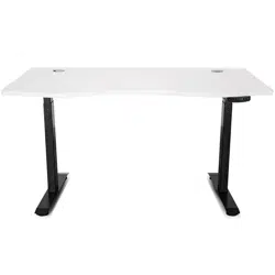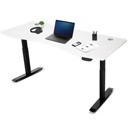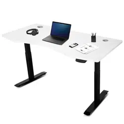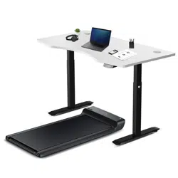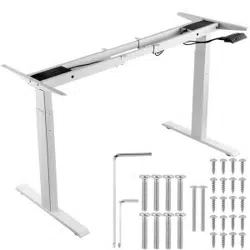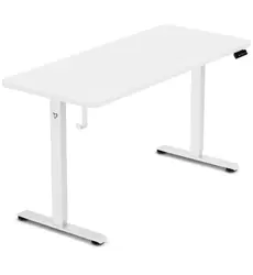
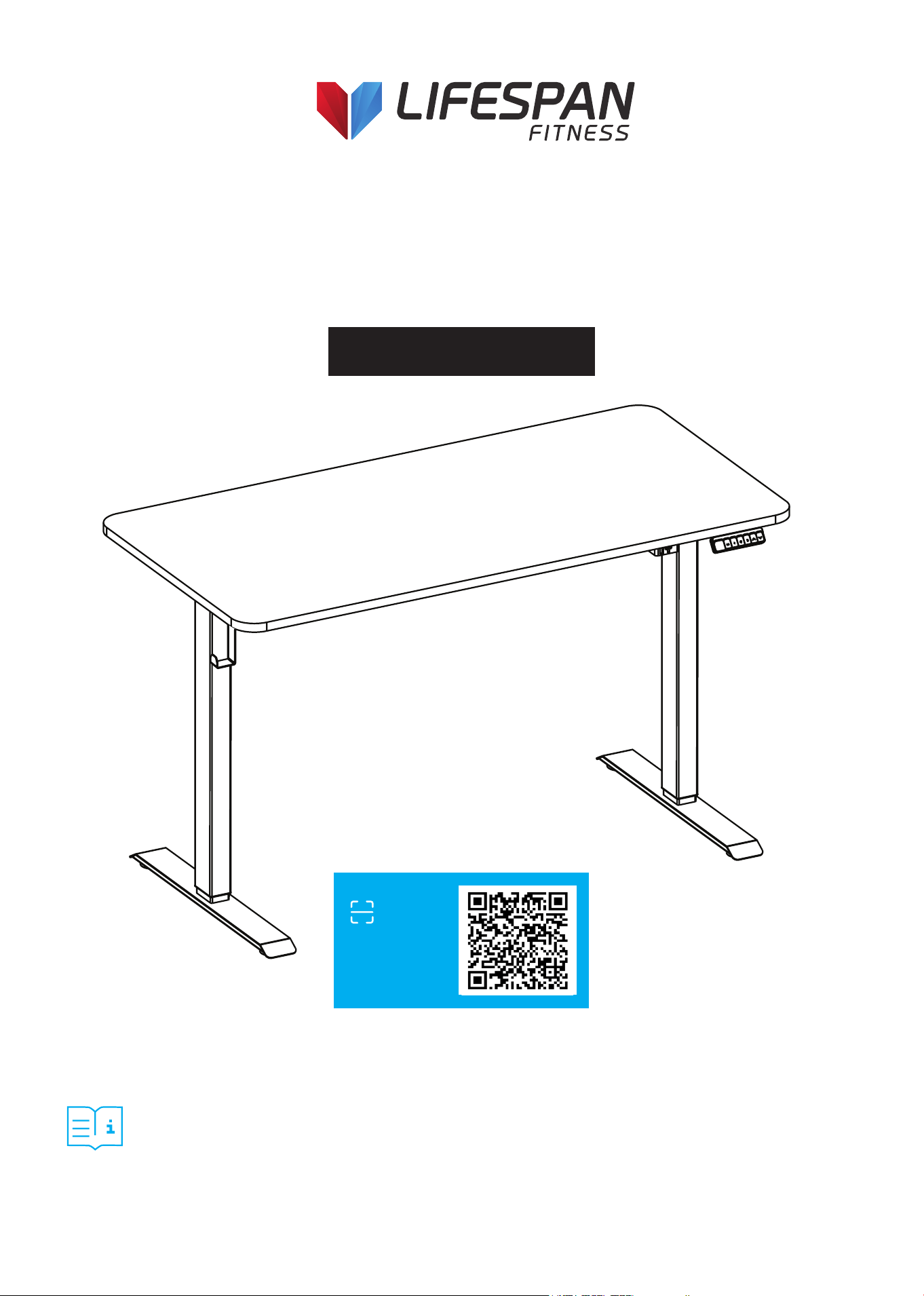
Product may vary slightly from the item pictured due to model upgrades.
Read all instructions carefully before using this product.
Retain this owner’s manual for future reference.
NOTE:
This manual may be subject to updates or changes. Up to date manuals are available through our
website at www.lifespanfitness.com.au
ErgoDesk Electric Standing
Desk Top (120cm/140cm)
and Frame
USER MANUAL
Find the
Digital Manual
Online

2
TABLE OF
CONTENTS
I. Setup and Installation . . . . . . . . . . . . . . . . . . . . . . . . . . . . . . . . . . . . . . . . 03
II. Important Safety Instructions . . . . . . . . . . . . . . . . . . . . . . . . . . . . . . . . 04
III. Assembly Instructions . . . . . . . . . . . . . . . . . . . . . . . . . . . . . . . . . . . . . . . . 05
IV. Operation Guide . . . . . . . . . . . . . . . . . . . . . . . . . . . . . . . . . . . . . . . . . . . . . . . 13
V. Warranty . . . . . . . . . . . . . . . . . . . . . . . . . . . . . . . . . . . . . . . . . . . . . . . . . . . . . . . 14
| TABLE OF CONTENTS

3
I. SETUP AND INSTALLATION
• Once the desk has been assembled, adjust the feet so that the desk is level and does not shift during
use.
• After leveling, connect the desk to a 110V or 240V outlet. The desk is now ready for use.
• Check that no cables can get jammed or pinched during movement.
• Choose a placement for the desk that is a safe distance from window frames, radiators, furniture, and
walls to avoid people getting stuck or trapped.
• Ensure the desktop does not touch the wall during movement.
• Do not place any objects taller than 50 cm (20") underneath the desk.
• After assembly, when moving the desk, DO NOT lift the desk by the desktop. This can stress the
fasteners connecting the desk base to the desktop.
• To move the desk, lower it completely and lift from the desk base, or remove the desktop first.
SETUP AND INSTALLATION |

4
| ASSEMBLY INSTRUCTIONS
II. IMPORTANT SAFETY
INSTRUCTIONS
GENERAL SAFETY
• Improper use may cause property damage or bodily injury.
• Keep children and pets away from the desk during operation.
• These desks are designed only for the purposes described in this manual. Any other use is at the
user’s risk.
• Do not use in environments with high humidity or dampness.
• Do not sit, stand, or lie on the desk.
• Do not move around, crawl, or lie under the desk frame.
• Do not place objects over 80 kg on the desktop.
• Avoid adjusting the desk height more than 20 times in a short period. Allow a 10-minute rest before
reuse.
• Unplug the power cord during thunderstorms or if the desk will not be used for an extended period.
• Do not immerse in water. Keep the desk away from liquids and heat sources.
• Do not disassemble or repair the product yourself. Only certified personnel may perform repairs.
WARNING: Read this manual carefully before operating this equipment.
NOTE: Follow all instructions to prevent accidents, injury, or equipment damage.
OPERATION SAFETY
• Ensure there are no obstacles in the desk’s path and no objects within 20 inches (500 mm)
underneath the desk.
• Body parts or items can be crushed if trapped between the desk and an immovable object.
• Keep hands and body parts clear of moving components to prevent pinching.
• Although the desk includes anti-collision protection, always supervise movement.
• NOTE: The anti-collision function is disabled during the reset process.
• Keep an eye on the desk while lowering or raising it.
• Ensure all cables and device cords are long enough for full range of motion. Items that are pulled off
the desk may fall and cause damage or injury.
• Do not use the desk if it malfunctions.
ENVIRONMENT & MAINTENANCE
• Operating temperature: 0 °C – 40 °C.
• Keep away from excessive humidity, extreme temperatures, corrosive gases, liquids, and dust.
• Turn off and unplug power before cleaning or inspection.
• Do not use water, alcohol, or strong cleaning chemicals. Use a dry or slightly damp cloth only.
• A manual reset is required after initial installation or power loss.
• The company accepts no liability or warranty for damage or injury caused by improper or abnormal
operation.
USAGE
• The desk height is adjustable to promote ergonomic working posture.
• Designed for indoor use only as described in this manual.
• Children should only use the desk under adult supervision.
• Under no circumstances does the manufacturer accept warranty or liability claims for damages
caused by improper use or handling of the desk beyond what is described in this operation manual.
5
III. ASSEMBLY INSTRUCTIONS
Installation Tips
• Do not fully tighten the screws during initial assembly. Once all parts are properly aligned, go back
and tighten all screws securely.
• Lay down a soft mat or old blanket before assembly to protect both the floor and the furniture from
scratches or damage.
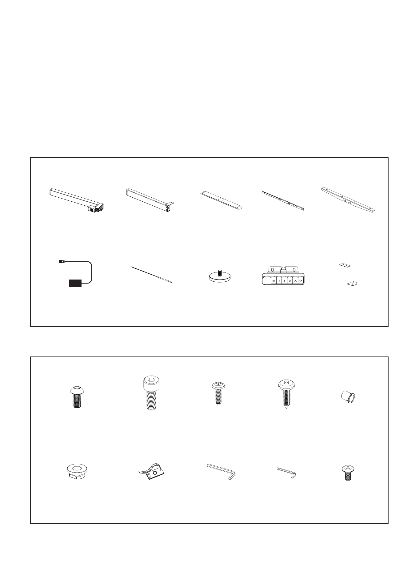
PARTS LIST
ASSEMBLY INSTRUCTIONS |
PARTS LIST
1
Lift Column A x 1
2
Lift Column B x 1
3
Foot x 2
4
Frame x 1
5
Side Bracket x 2
6
Power Cord x 1
7
Motor Rod x 1
8
Leveling Studs x 4
9
Handset x 1
10
Desk Hook x 1
A
Qty x 9
M6x12 Screws
B
Qty x 8
M6x16 Screws
C
Qty x 2
M4x12 Screws
D
Qty x 12
M5x12 Screws
E
Qty x 1
Guide Sleeve
F
Qty x 10
Washers
G
Qty x 5
Cable Clips
H
4mm
Allen Wrench
I
2mm
Allen Wrench
J
Qty x 4
M6x10 Screws
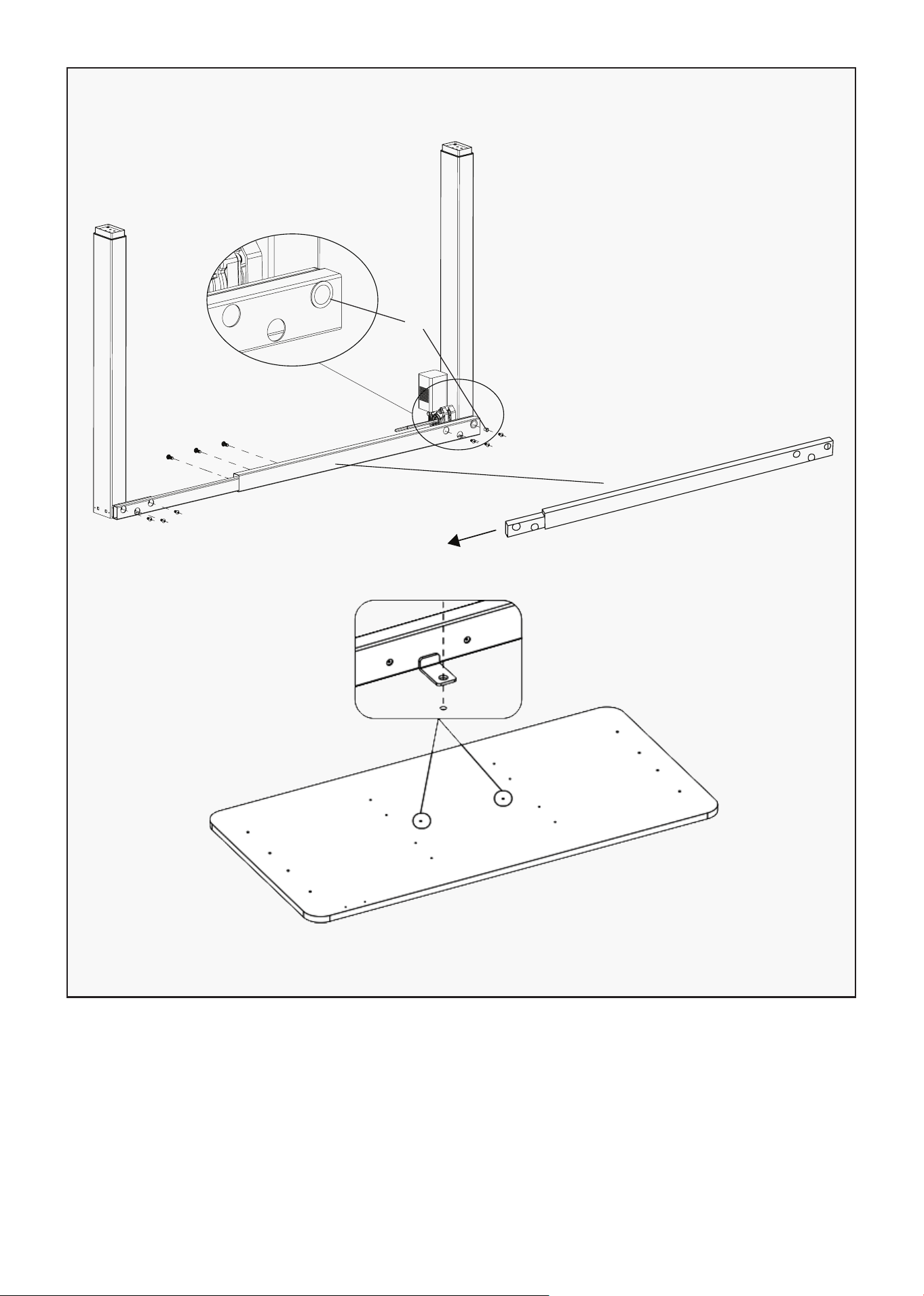
6 | ASSEMBLY INSTRUCTIONS
1. Place the frame(4) on a flat surface amd extend the bar to the suitable place ( desktop with pre
drilled hole for frame) then secure with M6*12 Screws(A).
2. Attach Lift Column A (1) and Lift Column B (2) to each end of the Frame (4) using M6x12 Screws (A).
3. Insert the Guide Sleeve (E) into the corresponding slot on Lift Column A (1) as shown in the diagram.
4. Once all components are aligned, securely tighten all screws.
STEP 1: Assemble the Lift Columns and Frame
2
A
A
4
E
1
A
1 Lift Column A x 1
2 Lift Column B x 1
4 Frame x 1
A M6x12 Screws x 9
E Guide Sleeve x 1
7
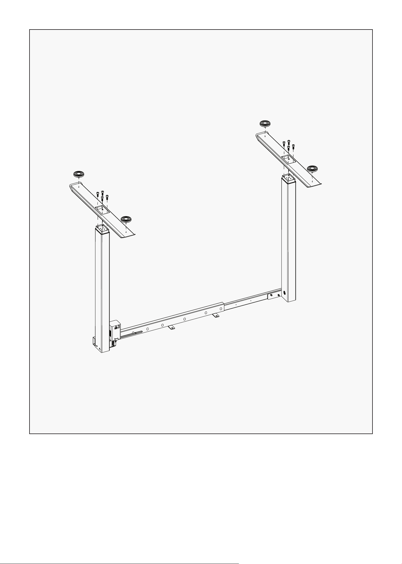
1. Position the Feet (3) at the bottom of each Lift Column as shown in the diagram.
2. Secure each Foot (3) using M6x16 Screws (B) — four screws per foot. Insert all screws before
tightening to ensure proper alignment.
3. Screw the Leveling Studs (8) into the threaded holes located at the ends of each Foot (3).
4. Adjust the Leveling Studs as needed to ensure the desk stands evenly on the floor.
STEP 2: Attach the Feet and Leveling Studs
8
8
B
B
3
3
3 Foot x 2
8 Leveling Studs x 4
B M6x16 Screws x 8
ASSEMBLY INSTRUCTIONS |
8
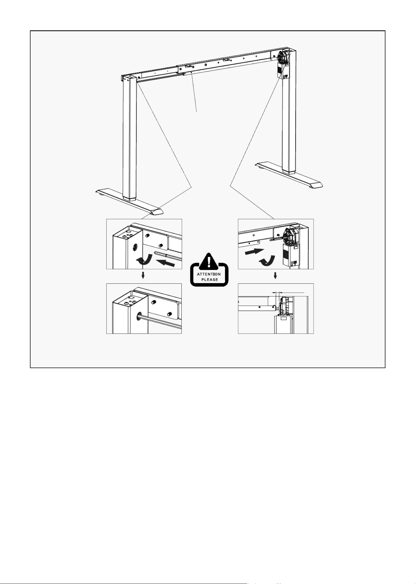
1. Place the table frame onto the feet.
2. Extend the Motor Rod (7) to its full length using 2mm Allen Key on the second hole as indicated on the
image. Turn the Allen Key clockwise to loose.
3. Insert the Motor Rod (7) into the gearbox completely, ensuring it is properly seated (refer to the
illustration).
4. Make sure there is less than 1 inch of distance between the motor rod and the motor after installation.
5. Once the rod is fully inserted, tighten the Motor Rod on the second hole using 2mm Allen key and
turning counter clockwise.
ATTENTION:
• Ensure the motor rod is fully inserted into the gearbox before operation.
• Improper insertion or excessive gap between components may cause malfunction or noise during
adjustment.
STEP 3: Install the Motor Rod
7
Tighten the screws with
the 2mm Allen Wrench
1 inch
Please insert motor
rod into the gear
box completely,
under the help of
circlip.
Please keep less
1 inch distance
between the
motor rod and
motor.
7 Motor Rod x 1
| ASSEMBLY INSTRUCTIONS
9
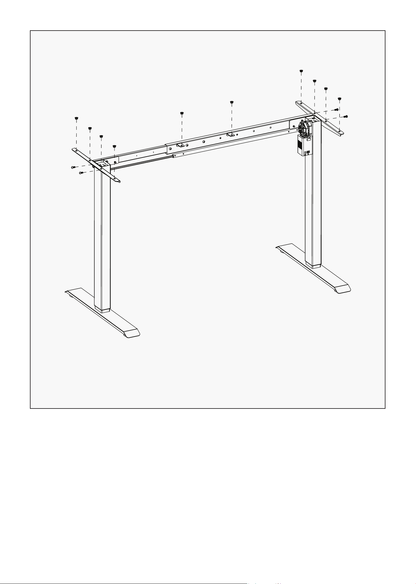
1. Align each Side Bracket (5) with the mounting holes located at both ends of the Frame.
2. Secure each Side Bracket (5) using M6x10 Screws (J), two screws per bracket. Insert all screws before
tightening to ensure proper alignment. Once both brackets are positioned correctly, tighten the
screws firmly.
3. Place 4x Washers (F) on top of each Side Bracket as pictured.
4. Place another 2x Washers (F) on the tabs in the middle of the Frame (4).
TIP: Ensure that both side brackets are level and securely fastened to maintain the stability of the desk
frame.
STEP 4: Attach the Side Brackets
F
F
F
J
J
5
5 Side Bracket x 2
F Washers x 10
J M6x10 Screws x 4
ASSEMBLY INSTRUCTIONS |
10
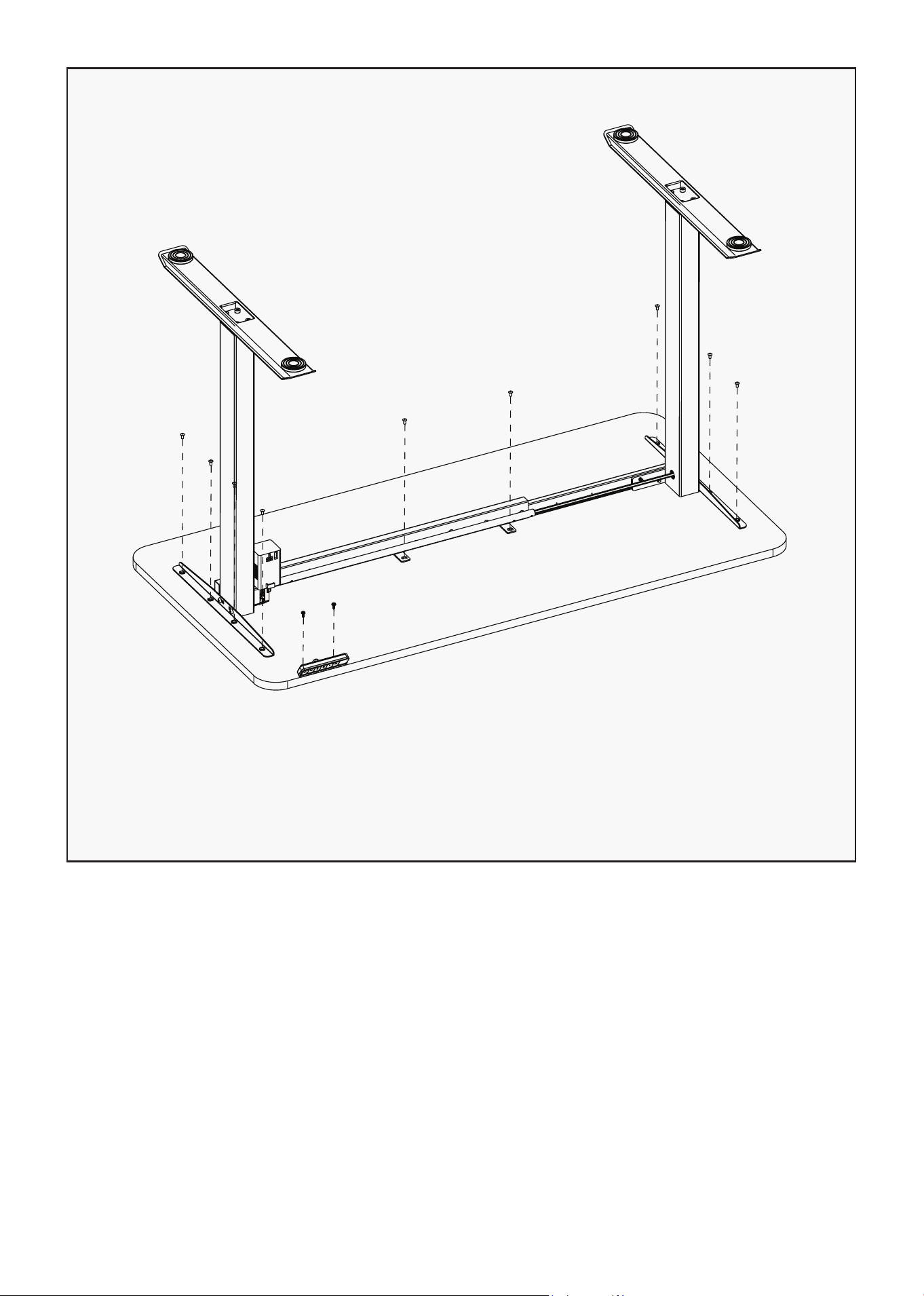
1. Carefully place the assembled desk frame upside down on the underside of the desktop as shown in
the diagram.
2. Align the Side Brackets and Frame with the pre-drilled holes on the desktop.
3. Secure the frame to the desktop using M5x12 Screws (D) — use all 10 screws.
4. Insert all screws loosely at first to ensure correct alignment, then tighten them securely once all are
in place.
5. Position the handset in a convenient location where it can be easily reached during desk operation.
Secure the Handset (9) using M4 x 12 Screws (C).
TIP: Ensure the desktop is positioned evenly so that the frame is centered before tightening all screws
completely.
STEP 5: Attach the Desktop
D
D
D
C
9
9 Handset x 1
C M4x12 Screws x 2
D M5x12 Screws x 10
| ASSEMBLY INSTRUCTIONS
11
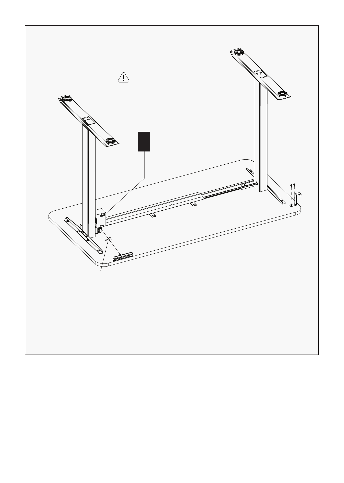
1. Attach the Desk Hook (10) using M5 x 12 Screws (D).
2. Connect the Handset Cord and Power Cord (6) to the motor and ensure it is firmly plugged in.
4. Use the Cable Pads (G) to neatly secure and organize all cables along the underside of the desk frame.
5. Press the cable clips firmly onto clean surfaces to ensure proper adhesion.
TIP: Avoid stretching or tangling the cables. Leave enough slack to allow smooth height adjustment
without pulling on the cords.
STEP 6: Install the Handset and Power Cord
6
D
G
Hook and Handset can be
mounted on the left or right.
6 Power Cord x 1
10 Desk Hook x 1
D M5x12 Screws x 2
G Cable Clips x 5
ASSEMBLY INSTRUCTIONS |

12
Before plugging the desk into a power outlet, ensure the following:
• The lift columns are level and set to their lowest position.
• All screws are securely tightened to prevent noise or wobbling during operation.
Activate the desk by following these steps:
• Press and hold the down button for 10–15 seconds until the desk stutters and beeps.
• Release the button — your desk is now ready for use.
Ready to Use
| ASSEMBLY INSTRUCTIONS

13
IV. OPERATION GUIDE
1. Memory Desired Height
• Press the "M" button — the display will flash "S–".
• Press a number key (1–3) to set and save the desired height position.
2. Advanced Safety Feature – Lock and Unlock the Table
• Press and hold both the Up (▲) and Down (▼) buttons simultaneously for 5 seconds.
• The display will show "LOC", and all single buttons will become inactive — the desk will not move.
• To unlock, press and hold the Up (▲) and Down (▼) buttons together again for 5 seconds until the
"LOC" indicator disappears.
3. Reset the Table
If the display shows an Error Code or "RST", please reset the table as follows:
1. Unplug the power cord from the control box.
2. Unplug the keypad cable from the control box.
3. Wait 30 seconds, then reconnect all cables.
4. Press and hold the Down (▼) button for 10–15 seconds until the desk stutters and beeps.
5. Release the Down (▼) button — the desk is now reset.
CAUTION: If the keypad displays "HOT"
Unplug the desk and allow it to cool for a few minutes before plugging it back in and resuming
operation.
OPERATION GUIDE |

14
V. WARRANTY
AUSTRALIAN CONSUMER LAW
Many of our products come with a guarantee or warranty from the manufacturer. In addition, they come
with guarantees that cannot be excluded under the Australian Consumer Law. You are entitled to a
replacement or refund for a major failure and compensation for any other reasonably foreseeable loss
or damage.
You are entitled to have the goods repaired or replaced if the goods fail to be of acceptable quality and
the failure does not amount to a major failure. Full details of your consumer rights may be found at
www.consumerlaw.gov.au.
Please visit our website to view our full warranty terms and conditions:
http://www.lifespanfitness.com.au/warranty-repairs
WARRANTY AND SUPPORT
Any claim against this warranty must be made through your original place of purchase.
Proof of purchase is required before a warranty claim may be processed.
If you have purchased this product from the Official Lifespan Fitness website, please visit
https://lifespanfitness.com.au/warranty-form
For support outside of warranty, if you wish to purchase replacement parts or request a repair or
service, please visit https://lifespanfitness.com.au/warranty-form and fill in our Repair/Service
Request Form or Parts Purchase Form.
Scan this QR code with your device to go to lifespanfitness.com.au/warranty-form
| WARRANTY


WWW.LIFESPANFITNESS.COM.AU