
i
Vigor2928 Series
Multi-WAN Security Router
Quick Start Guide
(for RF Model)
Version: 1.0
Firmware Version: V5.4.0
(For future update, please visit DrayTek web site)
Date: 13 August 2026

iii
Intellectual Property Rights (IPR) Information
Copyrights
© All rights reserved. This publication contains information that is protected by
copyright. No part may be reproduced, transmitted, transcribed, stored in a retrieval
system, or translated into any language without written permission from the copyright
holders.
Trademarks
The following trademarks are used in this document:
Microsoft is a registered trademark of Microsoft Corp.
Windows, 8, 10, 11 and Explorer are trademarks of Microsoft Corp.
Apple and Mac OS are registered trademarks of Apple Inc.
Other products may be trademarks or registered trademarks of their respective
manufacturers.
Safety Instructions and Approval
Safety Instructions
Read the installation guide thoroughly before you set up the router.
The router is a complicated electronic unit that may be repaired only be
authorized and qualified personnel. Do not try to open or repair the router yourself.
Do not place the router in a damp or humid place, e.g. a bathroom.
Do not stack the routers.
The router should be used in a sheltered area, within a temperature range of 0 to
+40 Celsius.
Do not expose the router to direct sunlight or other heat sources. The housing and
electronic components may be damaged by direct sunlight or heat sources.
Do not deploy the cable for LAN connection outdoor to prevent electronic shock
hazards.
Do not power off the router when saving configurations or firmware upgrades. It
may damage the data in a flash. Please disconnect the Internet connection on
the router before powering it off when a TR-069/ ACS server manages the router.
Keep the package out of reach of children.
When you want to dispose of the router, please follow local regulations on
conservation of the environment.
Warranty
We warrant to the original end user (purchaser) that the router will be free from any
defects in workmanship or materials for a period of two (2) years from the date of
purchase from the dealer. Please keep your purchase receipt in a safe place as it
serves as proof of date of purchase. During the warranty period, and upon proof of
purchase, should the product have indications of failure due to faulty workmanship
and/or materials, we will, at our discretion, repair or replace the defective products or
components, without charge for either parts or labor, to whatever extent we deem
necessary tore-store the product to proper operating condition. Any replacement will
consist of a new or re-manufactured functionally equivalent product of equal value,
and will be offered solely at our discretion. This warranty will not apply if the product is
modified, misused, tampered with, damaged by an act of God, or subjected to
abnormal working conditions. The warranty does not cover the bundled or licensed
software of other vendors. Defects which do not significantly affect the usability of the
product will not be covered by the warranty. We reserve the right to revise the manual
and online documentation and to make changes from time to time in the contents
hereof without obligation to notify any person of such revision or changes.
v
Declaration of Conformity
Hereby, DrayTek Corporation declares that the equipment type Vigor2928 is in compliance with Radio Equipment Directive
2014/53/EU, Low Voltage Directive 2014/35/EU and RoHS 2011/65/EU.
The full text of the EU Declaration of Conformity is available at the following internet address:
https://fw.draytek.com.tw/Vigor2928/Document/CE/
Manufacturer: DrayTek Corp.
Address: No. 26, Fushing Rd., Hukou, Hsinchu Industrial Park, Hsinchu 303, Taiwan
Product: Vigor2928 Wireless Series
Frequency Information for Europe area:
2.4GHz WLAN 2402MHz - 2482MHz, max. TX power: 19.98dBm *1
5GHz WLAN
5150MHz - 5350MHz, max. TX power: 22.8dBm *2
5470MHz - 5725MHz, max. TX power: 30dBm *2
5725MHz - 5850MHz, max. TX power: 13.9dBm *2
5G-NR
n1[1920-1980 MHz (TX); 2110-2170 MHz (RX)]; n3[1710-1785 MHz (TX); 1805-1880 MHz (RX)]; n7[2500-2570
MHz (TX); 2620-2690 MHz (RX)]; n8[880-915 MHz (TX); 925-960 MHz (RX)]; n20[832-862 MHz (TX);
791-821 MHz (RX)]; n28[703-748 MHz (TX); 758-803 MHz (RX)]; n38[2570-2620 MHz (TX/RX)];
n40[2300-2400 MHz (TX/RX)] ; n77[3300-4200 MHz (TX/RX)] ; n78[3300-3800 MHz (TX/RX)] *4
LTE
B1[1920-1980 MHz (TX); 2110-2170 MHz (RX)]; B3[1710-1785 MHz (TX); 1805-1880 MHz (RX)]; B7[2500-2570
MHz (TX); 2620-2690 MHz (RX)]; B8[880-915 MHz (TX); 925-960 MHz (RX)]; B20[832-862 MHz (TX);
791-821 MHz (RX)]; B28[703-748 MHz (TX); 758-803 MHz (RX)]; B38[2570-2620 MHz (TX); 2570-2620 MHz
(RX)]; B40[2300-2400 MHz (TX); 2300-2400 MHz (RX)] *3
3G B1[1920-1980 MHz (TX); 2110-2170 MHz (RX)]; B8[880-915 MHz (TX); 925-960 MHz (RX)] *3
Requirements in AT/BE/BG/CZ/DK/EE/FR/DE/IS/IE/IT/EL/ES/CY/LV/LI/LT/LU/HU/MT/NL/NO/PL/PT/RO/SI/
SK/TR/FI/SE/CH/HR/UK(NI). 5150MHz~5350MHz is for indoor use only.
(*1: for 2.4GHz WLAN model; *2: for 5GHz WLAN model; *3: for LTE model; *4: for 5G-NR model)
This product is designed for 5G-NR, LTE and 2.4GHz /5GHz WLAN network throughout the EC region.
Declaration of Conformity
Hereby, DrayTek Corporation declares that the equipment type Vigor2928 is in compliance with the Radio Equipment Regulations
2017 (SI 2017 No.1206, The Electrical Equipment (Safety) Regulations 2016 (SI 2016 No.1101), and The Restriction of the Use of Certain
Hazardous Substances in Electrical and Electronic Equipment Regulations 2012 (SI 2012 No. 3032).
The full text of the UKCA Declaration of Conformity is available at the following internet address:
https://fw.draytek.com.tw/Vigor2928/Document/CE/
Manufacturer: DrayTek Corp.
Address: No. 26, Fushing Rd., Hukou, Hsinchu Industrial Park, Hsinchu 303, Taiwan
Product: Vigor2928 Wireless Series
Importer: UK - CMS Distribution Limited, 15 Worship Street, London, EC2A 2DT
Ireland - CMS Distribution Limited, Bohola Road, Kiltimagh, Co Mayo, Ireland
Frequency Information for UK area:
2.4GHz WLAN 2402MHz - 2482MHz, max. TX power: 19.98dBm *1
5GHz WLAN
5150MHz - 5350MHz, max. TX power: 22.8dBm *2
5470MHz - 5725MHz, max. TX power: 30dBm *2
5725MHz - 5850MHz, max. TX power: 13.9dBm *2
5G-NR
n1[1920-1980 MHz (TX); 2110-2170 MHz (RX)]; n3[1710-1785 MHz (TX); 1805-1880 MHz (RX)]; n7[2500-2570
MHz (TX); 2620-2690 MHz (RX)]; n8[880-915 MHz (TX); 925-960 MHz (RX)]; n20[832-862 MHz (TX);
791-821 MHz (RX)]; n28[703-748 MHz (TX); 758-803 MHz (RX)]; n38[2570-2620 MHz (TX/RX)];
n40[2300-2400 MHz (TX/RX)] ; n77[3300-4200 MHz (TX/RX)] ; n78[3300-3800 MHz (TX/RX)] *4
LTE
B1[1920-1980 MHz (TX); 2110-2170 MHz (RX)]; B3[1710-1785 MHz (TX); 1805-1880 MHz (RX)]; B7[2500-2570
MHz (TX); 2620-2690 MHz (RX)]; B8[880-915 MHz (TX); 925-960 MHz (RX)]; B20[832-862 MHz (TX);
791-821 MHz (RX)]; B28[703-748 MHz (TX); 758-803 MHz (RX)]; B38[2570-2620 MHz (TX); 2570-2620
MHz (RX)]; B40[2300-2400 MHz (TX); 2300-2400 MHz (RX)] *3
3G B1[1920-1980 MHz (TX); 2110-2170 MHz (RX)]; B8[880-915 MHz (TX); 925-960 MHz (RX)] *3
Requirements in UK. 5150MHz~5350MHz is for indoor use only.
(*1: for 2.4GHz WLAN model; *2: for 5GHz WLAN model; *3: for LTE model;*4: for 5G-NR model)
This product is designed for 5G-NR, LTE and 2.4GHz /5GHz WLAN network use in the UK & Ireland.
vi
UK PSTI STATEMENT OF COMPLIANCE
We, DrayTek Corp., office at No.26, Fushing Rd., Hukou, Hsinchu Industrial Park, Hsinchu 303, Taiwan, declare under
our sole responsibility that the product
The full text of the PSTI Declaration of Conformity is available at the following internet address:
https://fw.draytek.com.tw/UK/PSTI/
Product name: Dual-WAN Security Router
Model number: Vigor2928be, Vigor2928be-4G, Vigor2928be-5G, Vigor2928-4G, Vigor2928-5G
Manufacturer: DrayTek Corp.
Address: No.26, Fushing Rd., Hukou, Hsinchu Industrial Park, Hsinchu 303, Taiwan
is in conformity with the relevant UK Statutory Instruments: The Product Security and Telecommunications
Infrastructure (Security Requirements for Relevant Connectable Products) Regulations 2023 (“Security
Requirements”).
Standard Version
The Product Security and
Telecommunications Infrastructure
Regulations
2023 Schedule 1
Support Period 5 years after the EOS notification
Please note that this statement of compliance, including the Defined Support Period stated herein, is only
applicable to products sold in the UK.
This Statement of Compliance is retained by DrayTek for 10 years after date of issue.
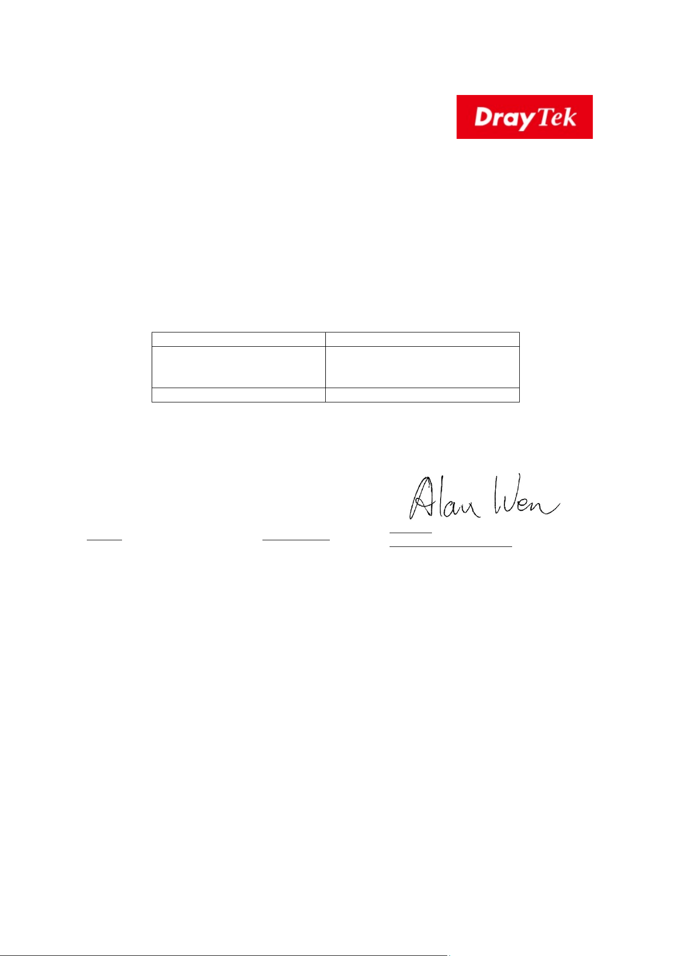
Hsinchu 25th Dec., 2025
Alan Wen
Chief Executive Officer, CEO
(place) (date) (Legal Signature)
vii
Regulatory Information
Federal Communication Commission Interference Statement
This equipment has been tested and found to comply with the limits for a Class B digital device, pursuant to Part 15
of the FCC Rules. These limits are designed to provide reasonable protection against harmful interference in a
residential installation. This equipment generates, uses and can radiate radio frequency energy and, if not installed
and used in accordance with the instructions, may cause harmful interference to radio communications. However,
there is no guarantee that interference will not occur in a particular installation. If this equipment does cause
harmful interference to radio or television reception, which can be determined by turning the equipment off and on,
the user is encouraged to try to correct the interference by one of the following measures:
Reorient or relocate the receiving antenna.
Increase the separation between the equipment and receiver.
Connect the equipment into an outlet on a circuit different from that to which the receiver is
connected.
Consult the dealer or an experienced radio/TV technician for help.
This device complies with Part 15 of the FCC Rules. Operation is subject to the following two conditions:
(1) This device may not cause harmful interference, and
(2) This device may accept any interference received, including interference that may cause undesired operation.
Company name ABP International Inc.
Address 13988 Diplomat Drive Suite 180 Dallas TX 75234
ZIP Code 75234 E-mail henry@abptech.com
USA Local
Representative
Contact Person Mr. Henry N Castillo Tel. (972)831-1600 140
Caution
Any changes or modifications not expressly approved by the grantee of this device could void the user's authority
to operate the equipment.
The antenna/transmitter should be kept at least 24 cm away from human body.
This product is an industrial/enterprise-grade networking device. It is designed and marketed for industrial and
commercial network environments, and is intended to be installed, configured, and maintained by qualified IT or
network professionals.
It is not intended, marketed, or sold for residential or consumer use, and is not designed for end-user
self-installation in a residential environment.
viii
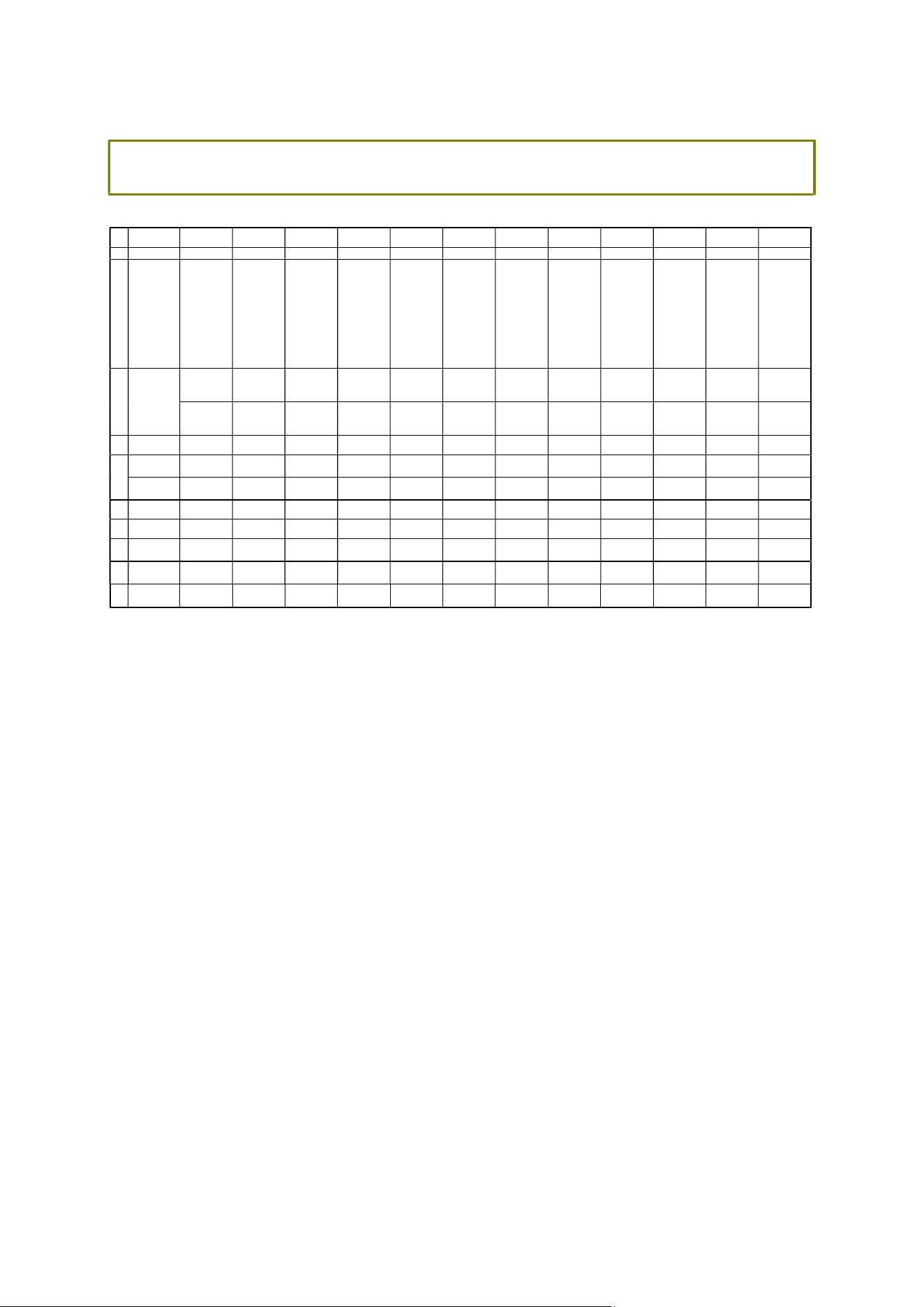
External Power Supply ErP Information
*The external power supply used for each product will be model dependent.
1 2 3 4 5 6 7 8 9 10 11 12
A Manufacturer
CWT CWT CWT CWT CWT APD APD APD APD MOSO MOSO MOSO
B
Address
No. 222, Sec. 2,
Nankan Rd., Lujhu
Township,
Taoyuan County
338, Taiwan
No. 222, Sec. 2,
Nankan Rd., Lujhu
Township,
Taoyuan County
338, Taiwan
No. 222, Sec. 2,
Nankan Rd., Lujhu
Township,
Ta
oyuan County
338, Taiwan
No. 222, Sec. 2,
Nankan Rd., Lujhu
Township,
Taoyuan County
338, Taiwan
No. 222, Sec. 2,
Nankan Rd., Lujhu
Township,
Taoyuan County
338, Taiwan
No.5, Lane 83,
Lung-Sou St.,
Taoyuan City
330, Taiwan
No.5, Lane 83,
Lung-Sou St.,
Taoyuan City
330, Taiwan
No.5, Lane 83,
Lung-Sou St.,
Taoyuan City
330, Taiwan
No.5, Lane 83,
Lung-Sou St.,
Taoyuan City
330, Taiwan
Sangtai
Industrial Park,
Guanwai
Xiaobaimang
Songbai Road,
Nanshan
District, 518108
Shenzhen,
Guangdong,
China
Sangtai
Industrial Park,
Guanwai
Xiaobaimang
Songbai Road,
Nanshan
District, 518108
Shenzhen,
Guangdong,
China
Sangtai
Industrial Park,
Guanwai
Xiaobaimang
Songbai Road,
Nanshan
District, 518108
Shenzhen,
Guangdong,
China
2ABB012F UK 2ABB018F UK 2ABL024F UK 2ABL030F UK 2ABN036F UK
WA-12M12FG WB-18D12FG WA-24Q12FG WA-36A12FG
MS-
V2000R120-
024Q0-GB
MSS-
V2500WR120-
030E0-GB
V30-V3000R12
0-036T0-GB
C
Model identifier
2ABB012F EU 2ABB018F EU 2ABL024F EU 2ABL030F EU 2ABN036F EU
WA-12M12FK WB-18D12FK WA-24Q12FK WA-36A12FK
MS-
V2000R120-
024Q0-DE
MSS-
V2500WR120-
030E0-DE
V30-V3000R12
0-036T0-DE
D
Input voltage
100~240V 100~240V 100~240V 100~240V 100~240V 100~240V 100~240V 100~240V 100~240V 100~240V 100~240V 100~240V
Input AC
frequency
50/60Hz 50/60Hz 50/60Hz 50/60Hz 50/60Hz 50/60Hz 50/60Hz 50/60Hz 50/60Hz 50/60Hz 50/60Hz 50/60Hz
E
Output voltage
DC
12.0V 12.0V 12.0V 12.0V 12.0V 12.0V 12.0V 12.0V 12.0V 12.0V 12.0V 12.0V
F
Output current
1.0A 1.5A 2.0A 2.5A 3.0A 1.0A 1.5A 2.0A 3.0A 2.0A 2.5A 3.0A
G
Output power
12.0W 18.0W 24.0W 30.0W 36.0W 12.0W 18.0W 24.0W 36.0W 24.0W 30.0W 36.0W
H
Average active
efficiency
84.9% 86.2% 87.6% 87.8% 89.8% 83.7% 85.4% 88.6% 88.2% 87.8% 89.5% 89.3%
I
Efficiency at low
load 10%
73.6% 78.0% 81.3% 83.3% 83.7% 74.5% 80.5% 86.4% 85.4% 85.4% 84.7% 87.7%
J
No-load power
consumption
0.07W 0.07W 0.07W 0.07W 0.07W 0.07W 0.10W 0.07W 0.10W 0.10W 0.08W 0.10W
For more update, please visit www.draytek.com.

ix
T
T
a
a
b
b
l
l
e
e
o
o
f
f
C
C
o
o
n
n
t
t
e
e
n
n
t
t
s
s
1. Package Content..................................................................................................1
2. Panel Explanation............................................................................................... 2
2.1 Vigor2928be..................................................................................................................................................................................................2
2.2 Vigor2928be-4G......................................................................................................................................................................................5
2.3 Vigor2928be-5G......................................................................................................................................................................................8
2.4 Vigor2928-4G.............................................................................................................................................................................................11
2.5 Vigor2928-5G............................................................................................................................................................................................13
3. Hardware Installation ......................................................................................15
3.1 Network Connection............................................................................................................................................................................15
3.2 Wall-Mounted Installation............................................................................................................................................................16
3.3 Antenna Installation...........................................................................................................................................................................17
4. Software Configuration .................................................................................. 20
5. Customer Service............................................................................................. 22
1
1
1
.
.
P
P
a
a
c
c
k
k
a
a
g
g
e
e
C
C
o
o
n
n
t
t
e
e
n
n
t
t
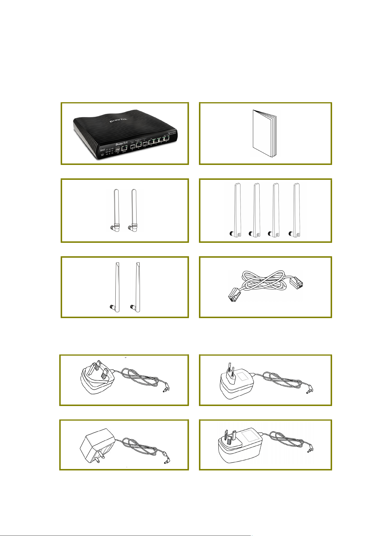
Take a look at the package content. If there is anything missed or damaged,
please contact DrayTek or dealer immediately.
Vigor Router Quick Start Guide
Antenna (4G)
Antenna (5G)
Antenna RJ-45 Cable (Ethernet)
The type of the power adapter depends on the country that the router will be
installed.
UK-type Power Adapter EU-type Power Adapter
USA/Taiwan-type Power Adapter AU/NZ-type Power Adapter
2
2
2
.
.
P
P
a
a
n
n
e
e
l
l
E
E
x
x
p
p
l
l
a
a
n
n
a
a
t
t
i
i
o
o
n
n
2
2
.
.
1
1
V
V
i
i
g
g
o
o
r
r
2
2
9
9
2
2
8
8
b
b
e
e
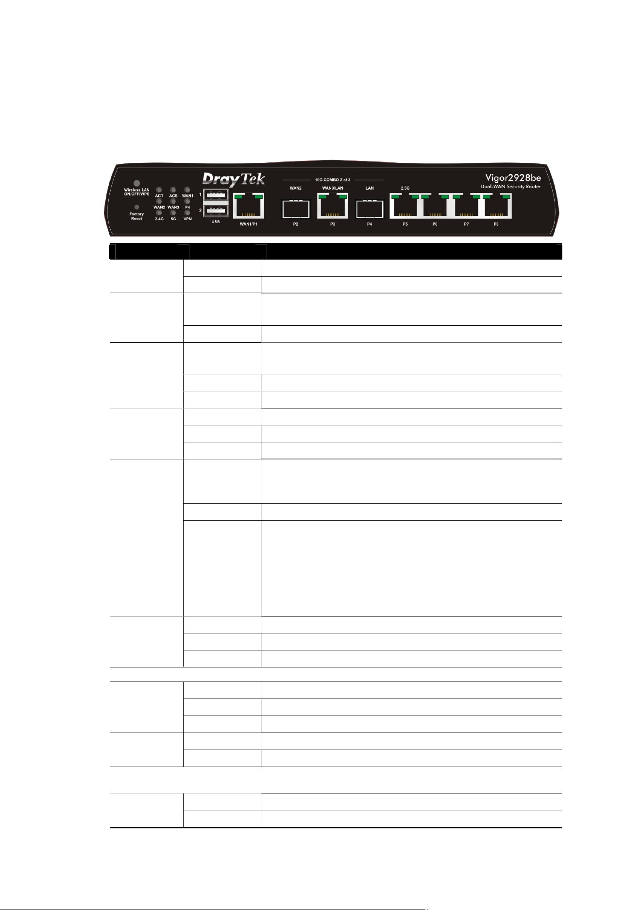
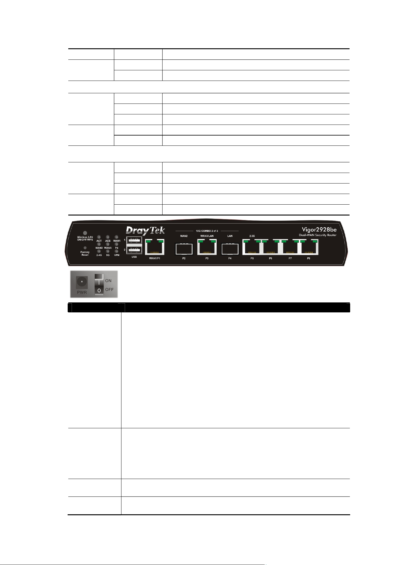
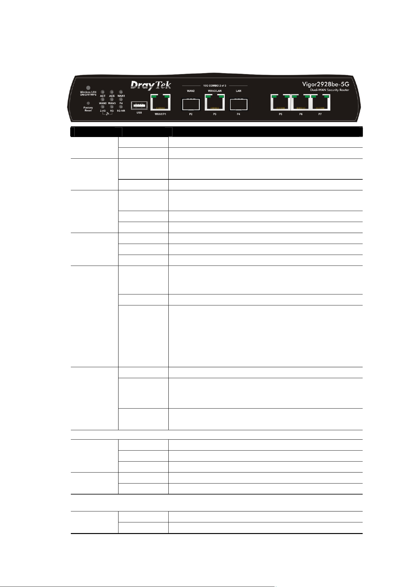
LED Status Explanation
Off The router is powered off.
ACT
Blinking The router is powered on and running normally.
On The router has registered and connected to
VigorACS server.
ACS
Off The router has not connected to VigorACS server.
On The interface is enabled on Configuration>>WAN
Connections.
Off Internet connection is not ready.
WAN1~3
Blinking The data is transmitting.
On The LAN port is connected.
Off The LAN port is disconnected.
P4
Blinking The data is transmitting.
On
2.4G/5G: Wireless access point with bandwidth
of 2.4GHz/5GHz is ready.
WLAN: Wireless access point is ready.
Off Wireless function is disabled.
2.4G/5G
Blinking
It will blink slowly while wireless traffic goes
through.
ACT and 2.4GHz/5GHz LEDs blink quickly and
simultaneously when WPS is working, and will
return to normal condition after two minutes.
(You need to setup WPS within 2 minutes.)
On The VPN tunnel is active.
Off VPN services are disabled
VPN
Blinking Traffic is passing through VPN tunnel.
WAN1/P1
On The port is connected.
Off The port is disconnected.
Left LED
Blinking The data is transmitting.
On The port is connected with 1000 Mbps.
Right LED
Off The port is connected with 10/100 Mbps.
WAN3/LAN/P3
On The port is connected.
Left LED
Off The port is disconnected.
3
Blinking The data is transmitting.
On The port is connected with 2.5/5/10 Gbps.
Right LED
Off The port is connected with 100/1000 Mbps.
LAN P5
On The port is connected.
Off The port is disconnected.
Left LED
Blinking The data is transmitting.
On The port is connected with 2.5 Gbps.
Right LED
Off The port is connected with 100/1000 Mbps
LAN P6-P8
On The port is connected.
Off The port is disconnected.
Left LED
Blinking The data is transmitting.
On The port is connected with 1000 Mbps.
Right LED
Off The port is connected with 10/100 Mbps
Interface Description
Wireless LAN
ON/OFF/WPS
Wireless band will be switched /changed according to the
button pressed and released. For example,
2.4G (On) and 5G (On) – in default.
2.4G (Off) and 5G (On) – pressed and released the
button once.
2.4G (On) and 5G (Off) – pressed and released the
button twice.
2.4G (Off) and 5G (Off) – pressed and released the
button three times.
When WPS function is enabled by web user interface, press
this button for more than 2 seconds to wait for client’s device
making
network connection through WPS.
Factory
Reset
Restore the default settings. Usage: Turn on the router (ACT
LED is blinking). Press the hole and keep for more than 5
seconds. When you see the ACT LED begins to blink rapidly
than usual, release the button. Then the router will restart
with the factory default configuration.
USB1~2
Connecter for a USB device (for 3G/4G USB Modem or printer
or thermometer).
WAN1 / P1
Connecter for the local network devices or modem for
accessing the Internet.

4
10G COMBO
2 of 3
Select any two ports to be the WAN port (either SPF+ or
Ethernet) and the LAN port. In this configuration, P2(SPF+) is
designated as the WAN port, and P4(SPF+) is designated as
the LAN port. Only P3 is a switchable Ethernet port, which can
be used for either WAN or LAN connections.
For example,
Selecting P2/P3: P2 is WAN2 port; P3 is LAN port.
Selecting P3/P4: P3 is WAN3 port; P4 is LAN port.
WAN# - Connecter for a modem for accessing the Internet.
LAN - Connecter for the local network device.
LAN P5-P8
Connecters for the local network devices.
In which, only P5 is available for 2.5G connection.
PWR
Connecter for a power adapter.
ON/OFF
Power Switch.
5
2
2
.
.
2
2
V
V
i
i
g
g
o
o
r
r
2
2
9
9
2
2
8
8
b
b
e
e
-
-
4
4
G
G
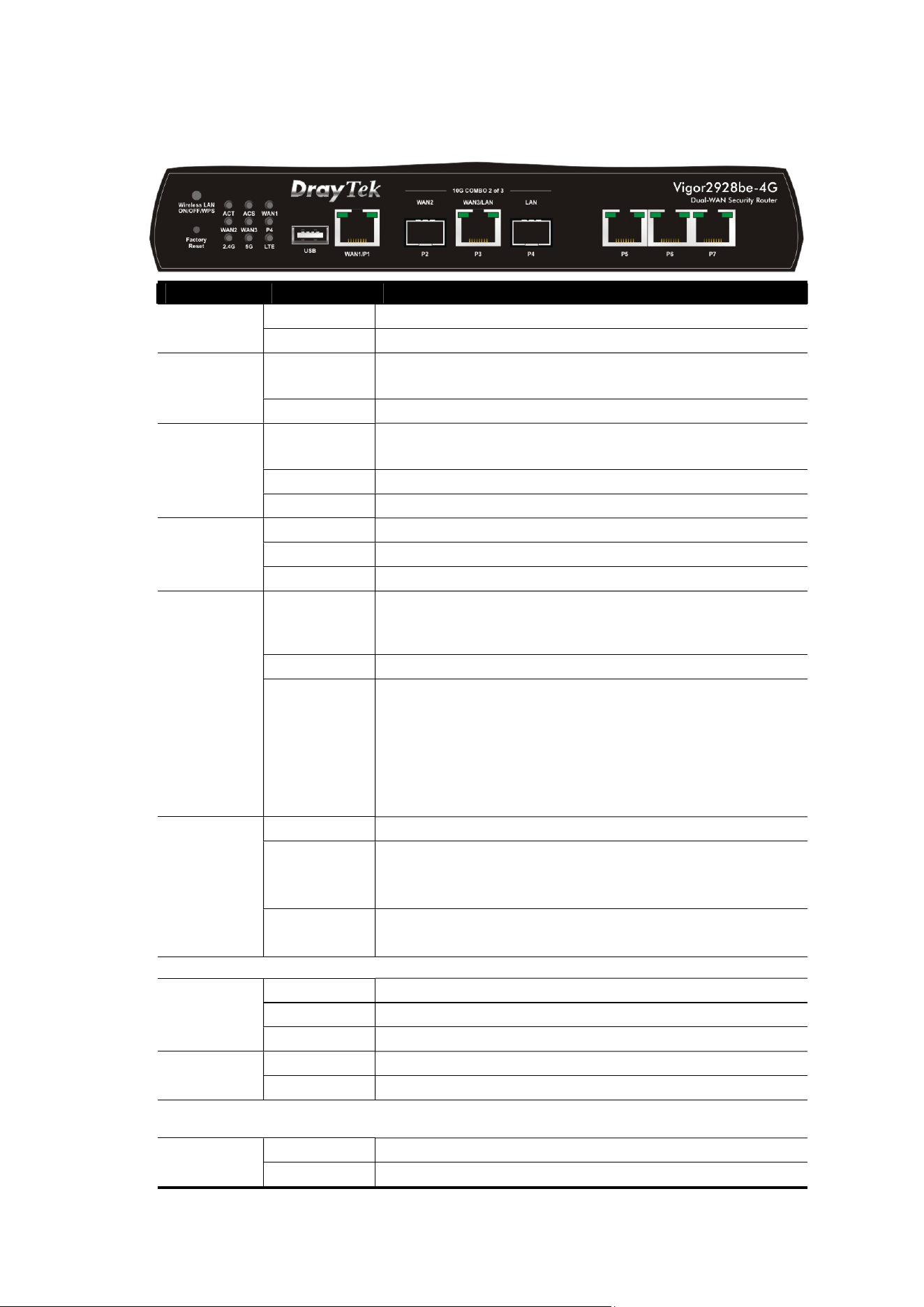
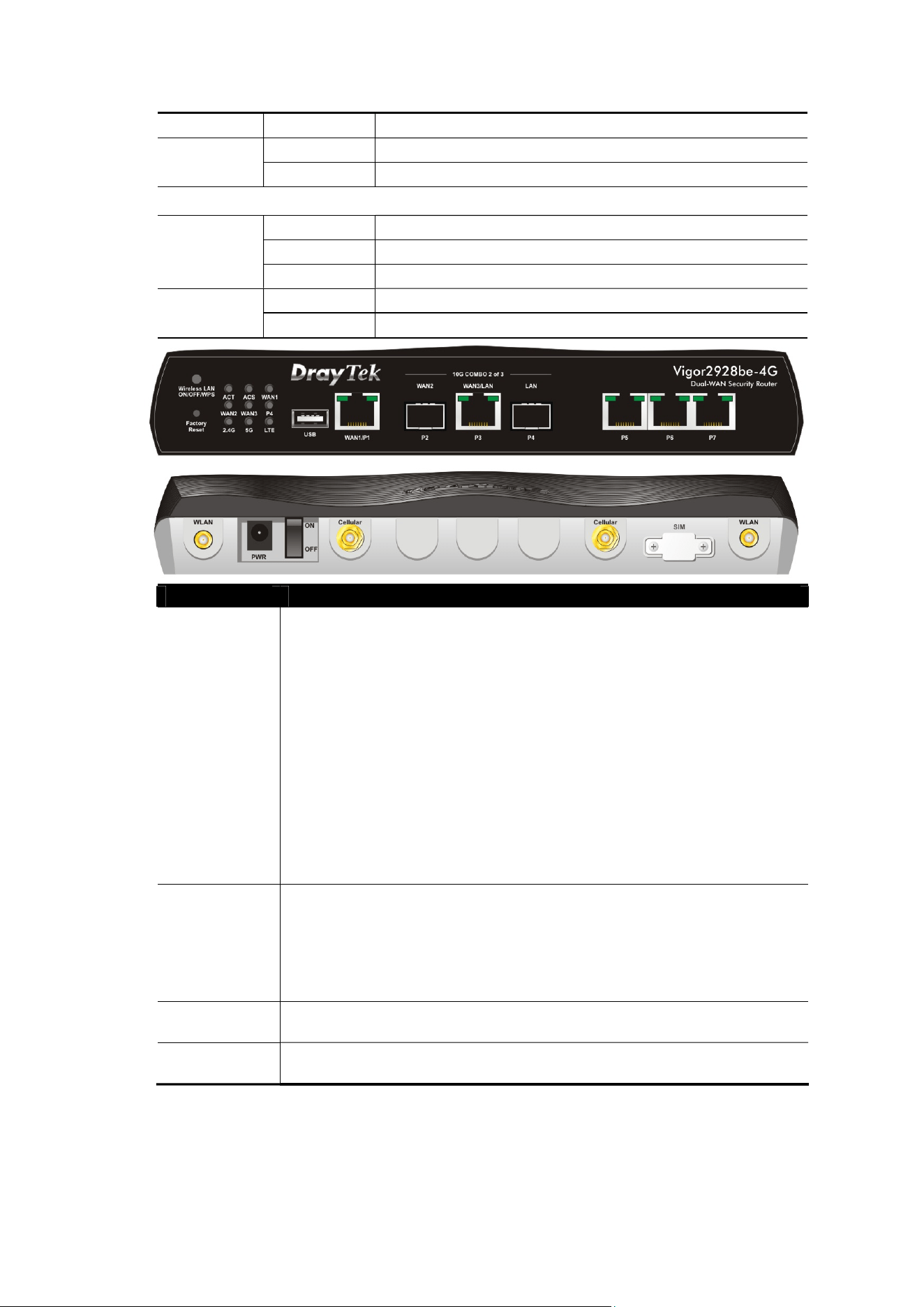
LED Status Explanation
Off The router is powered off.
ACT
Blinking The router is powered on and running normally.
On The router has registered and connected to
VigorACS server.
ACS
Off The router has not connected to VigorACS server.
On The interface is enabled on Configuration>>WAN
Connections.
Off Internet connection is not ready.
WAN1~3
Blinking The data is transmitting.
On The LAN port is connected.
Off The LAN port is disconnected.
P4
Blinking The data is transmitting.
On
2.4G/5G: Wireless access point with bandwidth
of 2.4GHz/5GHz is ready.
WLAN: Wireless access point is ready.
Off Wireless function is disabled.
2.4G/5G
Blinking
It will blink slowly while wireless traffic goes
through.
ACT and 2.4GHz/5GHz LEDs blink quickly and
simultaneously when WPS is working, and will
return to normal condition after two minutes.
(You need to setup WPS within 2 minutes.)
On LTE device is connected and ready for use.
Off LTE device is not detected, or has serious
problem (e.g., no SIM card, SIM pin error, SIM
deactivated, and etc.).
LTE
Blinking Slowly: LTE device is in dialing up.
Quickly: The data is transmitting.
WAN1/P1
On The port is connected.
Off The port is disconnected.
Left LED
Blinking The data is transmitting.
On The port is connected with 1000 Mbps.
Right LED
Off The port is connected with 10/100 Mbps.
WAN3/LAN/P3
On The port is connected.
Left LED
Off The port is disconnected.
6
Blinking The data is transmitting.
On The port is connected with 2.5/5/10 Gbps.
Right LED
Off The port is connected with 100/1000 Mbps.
LAN P5-P7
On The port is connected.
Off The port is disconnected.
Left LED
Blinking The data is transmitting.
On The port is connected with 2.5 Gbps.
Right LED
Off The port is connected with 100/1000 Mbps
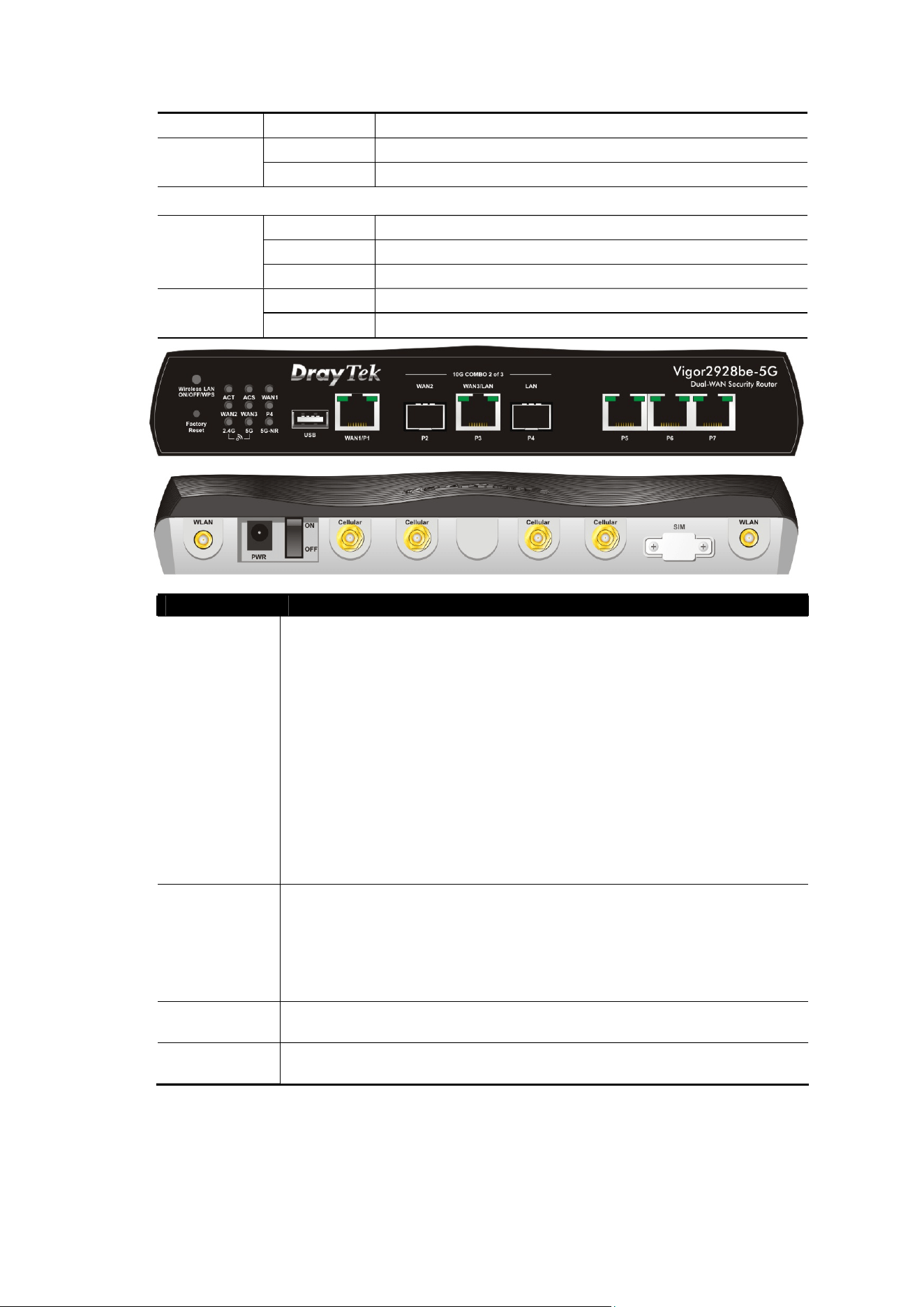
Interface Description
Wireless LAN
ON/OFF/WPS
Wireless band will be switched /changed according to the
button pressed and released. For example,
2.4G (On) and 5G (On) – in default.
2.4G (Off) and 5G (On) – pressed and released the
button once.
2.4G (On) and 5G (Off) – pressed and released the
button twice.
2.4G (Off) and 5G (Off) – pressed and released the
button three times.
When WPS function is enabled by web user interface, press
this button for more than 2 seconds to wait for client’s device
making
network connection through WPS.
Factory
Reset
Restore the default settings. Usage: Turn on the router (ACT
LED is blinking). Press the hole and keep for more than 5
seconds. When you see the ACT LED begins to blink rapidly
than usual, release the button. Then the router will restart
with the factory default configuration.
USB
Connecter for a USB device (for 3G/4G USB Modem or printer
or thermometer).
WAN1 / P1
Connecter for the local network devices or modem for
accessing the Internet.
7
10G COMBO
2 of 3
Select any two ports to be the WAN port (either SPF+ or
Ethernet) and the LAN port. In this configuration, P2(SPF+) is
designated as the WAN port, and P4(SPF+) is designated as
the LAN port. Only P3 is a switchable Ethernet port, which can
be used for either WAN or LAN connections.
For example,
Selecting P2/P3: P2 is WAN2 port; P3 is LAN port.
Selecting P3/P4: P3 is WAN3 port; P4 is LAN port.
WAN# - Connecter for a modem for accessing the Internet.
LAN - Connecter for the local network device.
LAN P5-P7 Connecters for the local network devices.
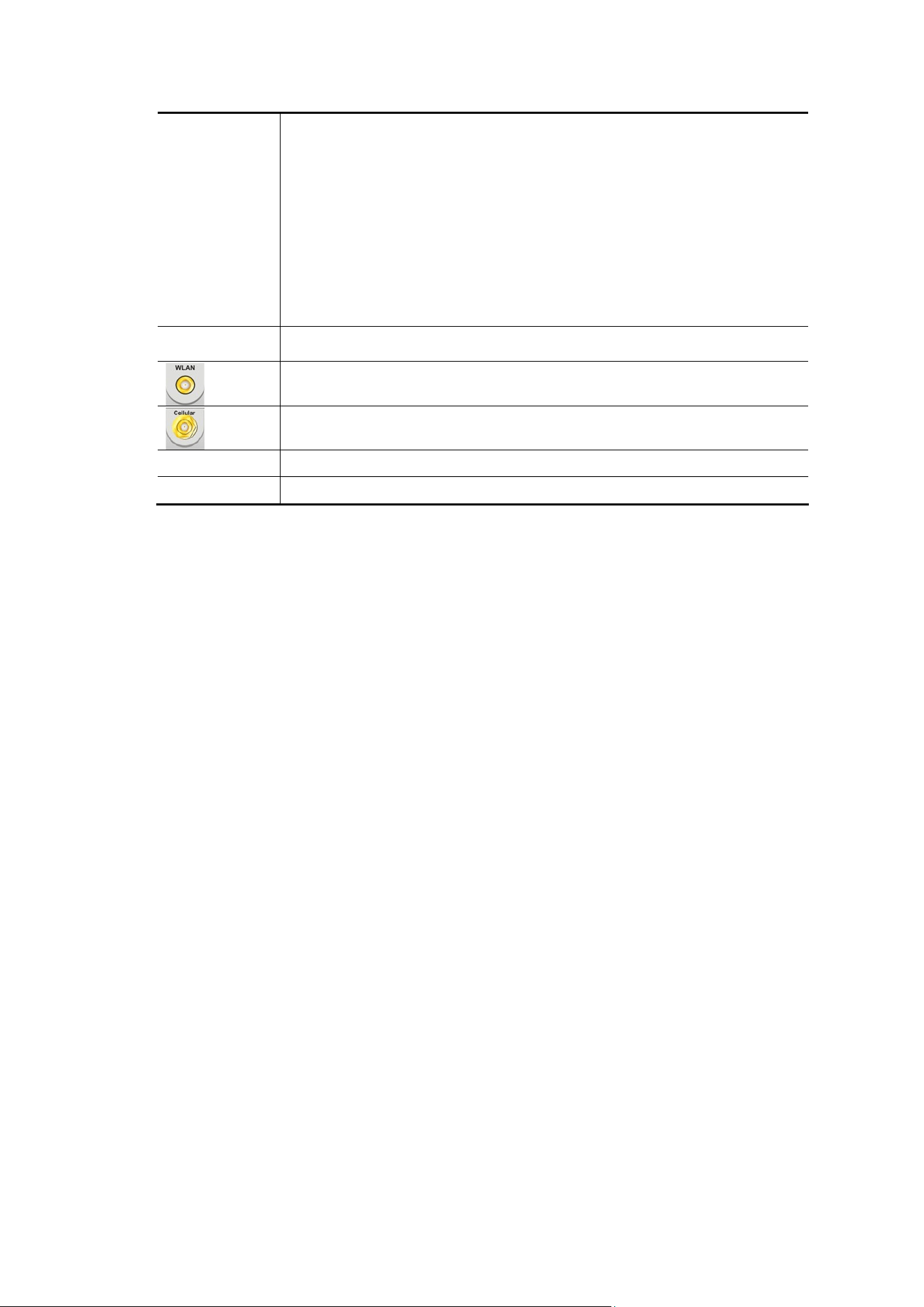
Connecter for installing WLAN antennas.
Connecter for installing antennas for the SIM application.
PWR
Connecter for a power adapter.
ON/OFF
Power Switch.
8
2
2
.
.
3
3
V
V
i
i
g
g
o
o
r
r
2
2
9
9
2
2
8
8
b
b
e
e
-
-
5
5
G
G
LED Status Explanation
Off The router is powered off.
ACT
Blinking The router is powered on and running normally.
On The router has registered and connected to
VigorACS server.
ACS
Off The router has not connected to VigorACS server.
On The interface is enabled on Configuration>>WAN
Connections.
Off Internet connection is not ready.
WAN1~3
Blinking The data is transmitting.
On The LAN port is connected.
Off The LAN port is disconnected.
P4
Blinking The data is transmitting.
On
2.4G/5G: Wireless access point with bandwidth
of 2.4GHz/5GHz is ready.
WLAN: Wireless access point is ready.
Off Wireless function is disabled.
2.4G/5G
Blinking
It will blink slowly while wireless traffic goes
through.
ACT and 2.4GHz/5GHz LEDs blink quickly and
simultaneously when WPS is working, and will
return to normal condition after two minutes.
(You need to setup WPS within 2 minutes.)
On 5G-NR device is connected and ready for use.
Off 5G-NR device is not detected, or has serious
problem (e.g., no SIM card, SIM pin error, SIM
deactivated, and etc.).
5G-NR
Blinking Slowly: 5G-NR device is in dialing up.
Quickly: The data is transmitting.
WAN1/P1
On The port is connected.
Off The port is disconnected.
Left LED
Blinking The data is transmitting.
On The port is connected with 1000 Mbps.
Right LED
Off The port is connected with 10/100 Mbps.
WAN3/LAN/P3
On The port is connected.
Left LED
Off The port is disconnected.
9
Blinking The data is transmitting.
On The port is connected with 2.5/5/10 Gbps.
Right LED
Off The port is connected with 100/1000 Mbps.
LAN P5-P7
On The port is connected.
Off The port is disconnected.
Left LED
Blinking The data is transmitting.
On The port is connected with 2.5 Gbps.
Right LED
Off The port is connected with 100/1000 Mbps
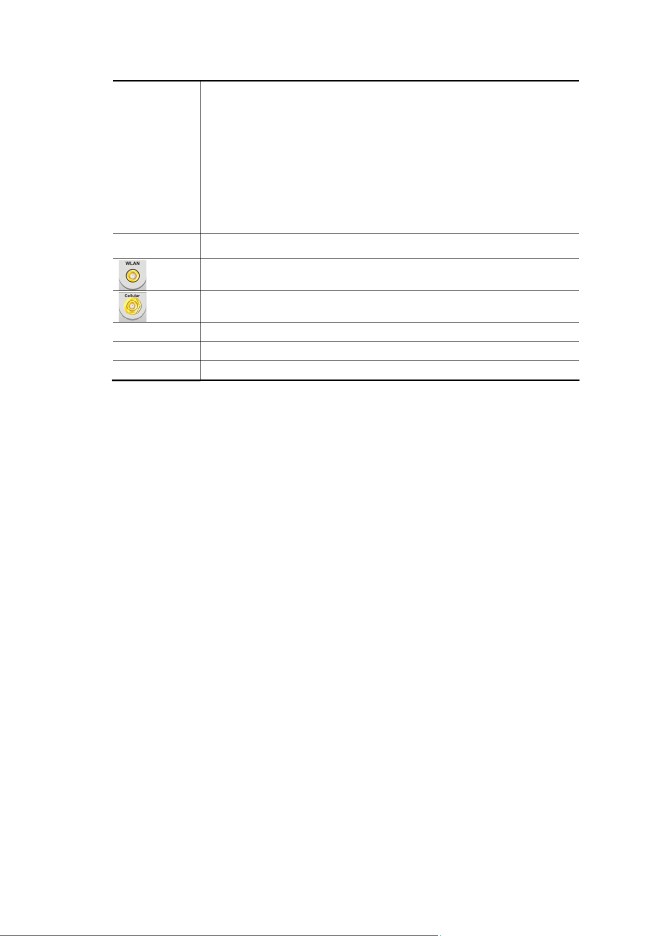
Interface Description
Wireless LAN
ON/OFF/WPS
Wireless band will be switched /changed according to the
button pressed and released. For example,
2.4G (On) and 5G (On) – in default.
2.4G (Off) and 5G (On) – pressed and released the
button once.
2.4G (On) and 5G (Off) – pressed and released the
button twice.
2.4G (Off) and 5G (Off) – pressed and released the
button three times.
When WPS function is enabled by web user interface, press
this button for more than 2 seconds to wait for client’s device
making
network connection through WPS.
Factory
Reset
Restore the default settings. Usage: Turn on the router (ACT
LED is blinking). Press the hole and keep for more than 5
seconds. When you see the ACT LED begins to blink rapidly
than usual, release the button. Then the router will restart
with the factory default configuration.
USB
Connecter for a USB device (for 3G/4G USB Modem or printer
or thermometer).
WAN1 / P1
Connecter for the local network devices or modem for
accessing the Internet.
10
10G COMBO
2 of 3
Select any two ports to be the WAN port (either SPF+ or
Ethernet) and the LAN port. In this configuration, P2(SPF+) is
designated as the WAN port, and P4(SPF+) is designated as
the LAN port. Only P3 is a switchable Ethernet port, which can
be used for either WAN or LAN connections.
For example,
Selecting P2/P3: P2 is WAN2 port; P3 is LAN port.
Selecting P3/P4: P3 is WAN3 port; P4 is LAN port.
WAN# - Connecter for a modem for accessing the Internet.
LAN - Connecter for the local network device.
LAN P5-P7
Connecters for the local network devices.
Connecter for installing WLAN antennas.
Connecter for installing antennas for the SIM application.
PWR
Connecter for a power adapter.
ON/OFF
Power Switch.
SIM Card Slots for installing SIM card(s).
11
2
2
.
.
4
4
V
V
i
i
g
g
o
o
r
r
2
2
9
9
2
2
8
8
-
-
4
4
G
G
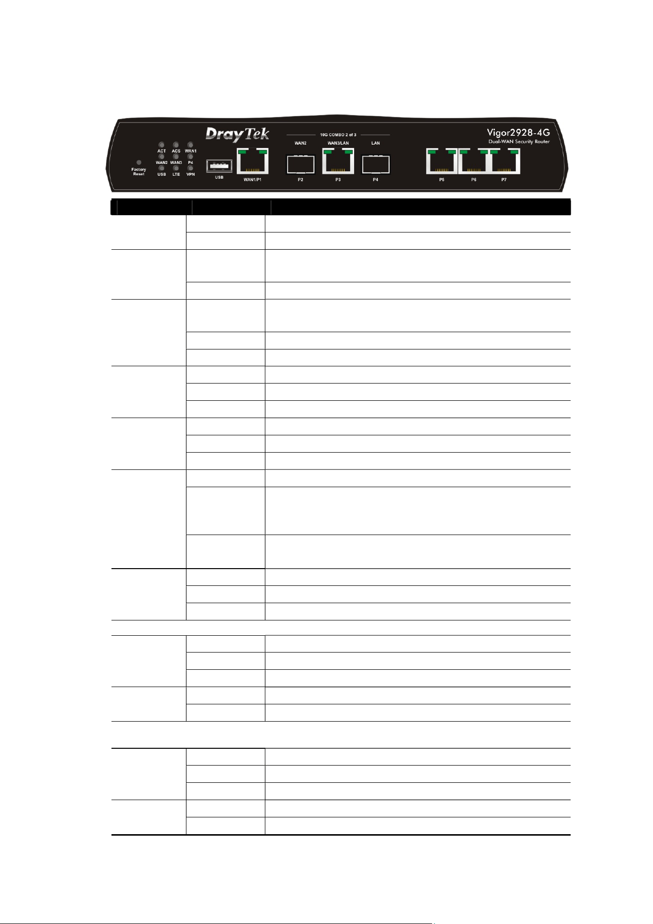
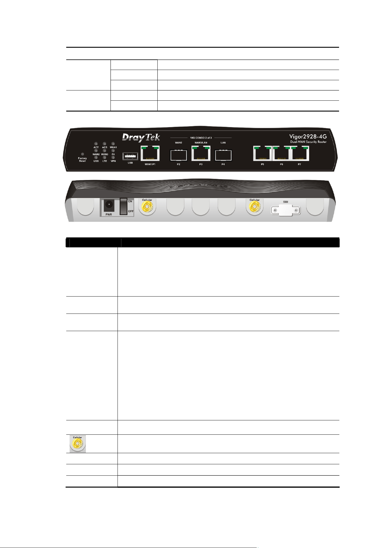
LED Status Explanation
Off The router is powered off.
ACT
Blinking The router is powered on and running normally.
On The router has registered and connected to
VigorACS server.
ACS
Off The router has not connected to VigorACS server.
On The interface is enabled on Configuration>>WAN
Connections.
Off Internet connection is not ready.
WAN1~3
Blinking The data is transmitting.
On The LAN port is connected.
Off The LAN port is disconnected.
P4
Blinking The data is transmitting.
On
USB device is connected and ready for use.
Off
No USB device is connected.
USB
Blinking
The data is transmitting.
On LTE device is connected and ready for use.
Off LTE device is not detected, or has serious
problem (e.g., no SIM card, SIM pin error, SIM
deactivated, and etc.).
LTE
Blinking Slowly: LTE device is in dialing up.
Quickly: The data is transmitting.
On The VPN tunnel is active.
Off VPN services are disabled
VPN
Blinking Traffic is passing through VPN tunnel.
WAN1/P1
On The port is connected.
Off The port is disconnected.
Left LED
Blinking The data is transmitting.
On The port is connected with 1000 Mbps.
Right LED
Off The port is connected with 10/100 Mbps.
WAN3/LAN/P3
On The port is connected.
Off The port is disconnected.
Left LED
Blinking The data is transmitting.
On The port is connected with 2.5/5/10 Gbps.
Right LED
Off The port is connected with 100/1000 Mbps.
12
LAN P5-P7
On The port is connected.
Off The port is disconnected.
Left LED
Blinking The data is transmitting.
On The port is connected with 1 Gbps.
Right LED
Off The port is connected with 100/1000 Mbps
Interface Description
Factory
Reset
Restore the default settings. Usage: Turn on the router (ACT
LED is blinking). Press the hole and keep for more than 5
seconds. When you see the ACT LED begins to blink rapidly
than usual, release the button. Then the router will restart
with the factory default configuration.
USB
Connecter for a USB device (for 3G/4G USB Modem or printer
or thermometer).
WAN1 / P1
Connecter for the local network devices or modem for
accessing the Internet.
10G COMBO
2 of 3
Select any two ports to be the WAN port (either SPF+ or
Ethernet) and the LAN port. In this configuration, P2(SPF+) is
designated as the WAN port, and P4(SPF+) is designated as
the LAN port. Only P3 is a switchable Ethernet port, which can
be used for either WAN or LAN connections.
For example,
Selecting P2/P3: P2 is WAN2 port; P3 is LAN port.
Selecting P3/P4: P3 is WAN3 port; P4 is LAN port.
WAN# - Connecter for a modem for accessing the Internet.
LAN - Connecter for the local network device.
LAN P5-P7
Connecters for the local network devices.
Connecter for installing antennas for the SIM application.
PWR
Connecter for a power adapter.
ON/OFF
Power Switch.
SIM Card Slots for installing SIM card(s).
13
2
2
.
.
5
5
V
V
i
i
g
g
o
o
r
r
2
2
9
9
2
2
8
8
-
-
5
5
G
G
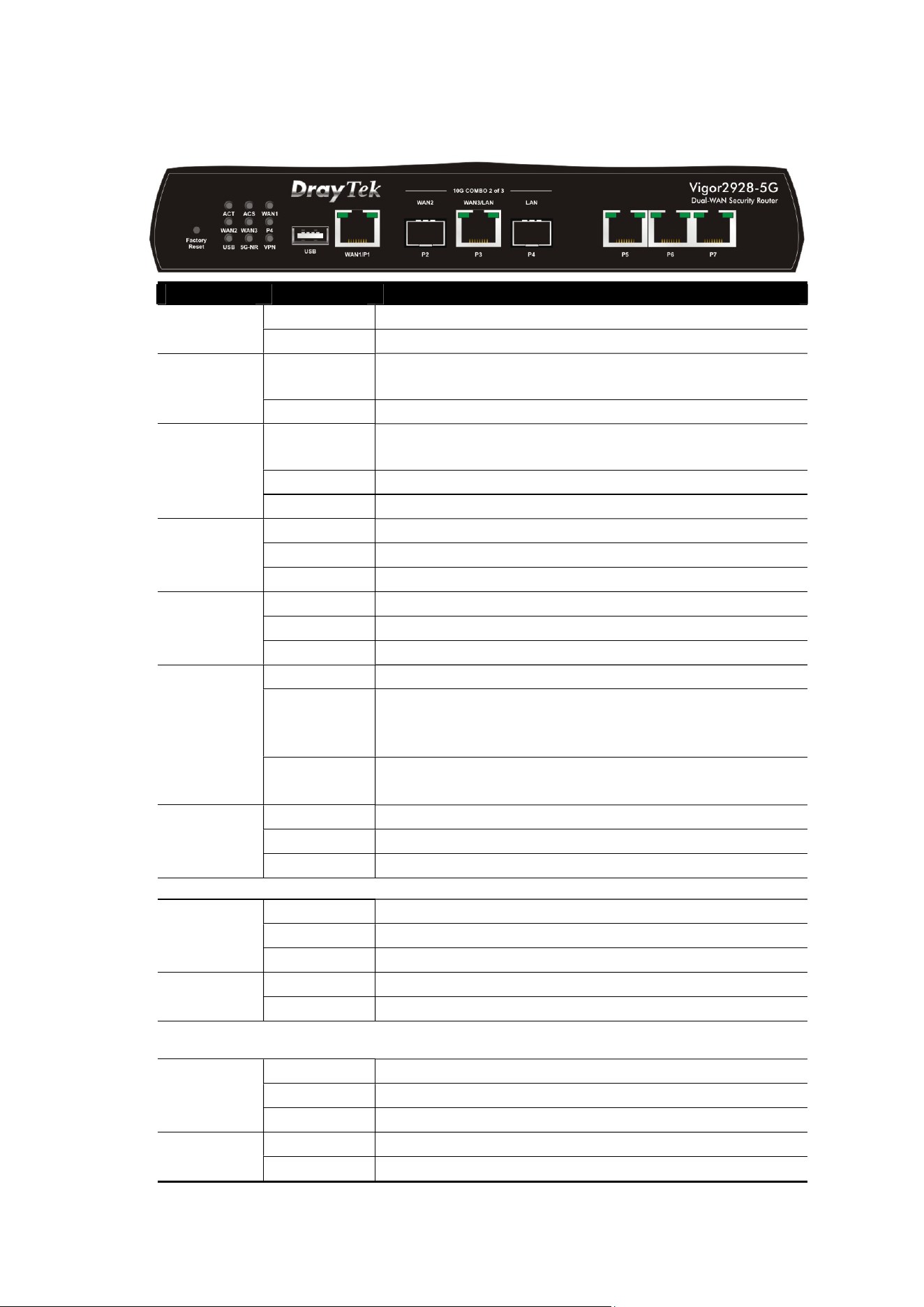
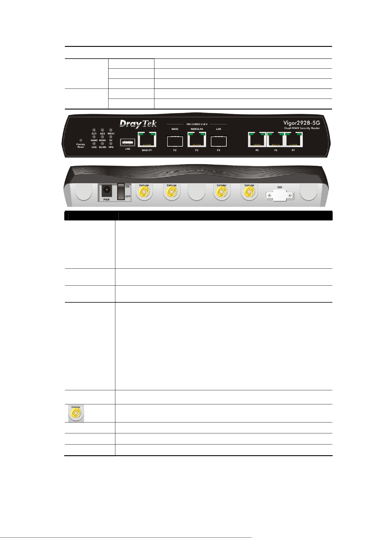
LED Status Explanation
Off The router is powered off.
ACT
Blinking The router is powered on and running normally.
On The router has registered and connected to
VigorACS server.
ACS
Off The router has not connected to VigorACS server.
On The interface is enabled on Configuration>>WAN
Connections.
Off Internet connection is not ready.
WAN1~3
Blinking The data is transmitting.
On The LAN port is connected.
Off The LAN port is disconnected.
P4
Blinking The data is transmitting.
On
USB device is connected and ready for use.
Off No USB device is connected.
USB
Blinking The data is transmitting.
On 5G-NR device is connected and ready for use.
Off 5G-NR device is not detected, or has serious
problem (e.g., no SIM card, SIM pin error, SIM
deactivated, and etc.).
5G-NR
Blinking Slowly: 5G-NR device is in dialing up.
Quickly: The data is transmitting.
On The VPN tunnel is active.
Off VPN services are disabled
VPN
Blinking Traffic is passing through VPN tunnel.
WAN1/P1
On The port is connected.
Off The port is disconnected.
Left LED
Blinking The data is transmitting.
On The port is connected with 1000 Mbps.
Right LED
Off The port is connected with 10/100 Mbps.
WAN3/LAN/P3
On The port is connected.
Off The port is disconnected.
Left LED
Blinking The data is transmitting.
On The port is connected with 2.5/5/10 Gbps.
Right LED
Off The port is connected with 100/1000 Mbps.
14
LAN P5-P7
On The port is connected.
Off The port is disconnected.
Left LED
Blinking The data is transmitting.
On The port is connected with 1 Gbps.
Right LED
Off The port is connected with 100/1000 Mbps
Interface Description
Factory
Reset
Restore the default settings. Usage: Turn on the router (ACT
LED is blinking). Press the hole and keep for more than 5
seconds. When you see the ACT LED begins to blink rapidly
than usual, release the button. Then the router will restart
with the factory default configuration.
USB
Connecter for a USB device (for 3G/4G USB Modem or printer
or thermometer).
WAN1 / P1
Connecter for the local network devices or modem for
accessing the Internet.
10G COMBO
2 of 3
Select any two ports to be the WAN port (either SPF+ or
Ethernet) and the LAN port. In this configuration, P2(SPF+) is
designated as the WAN port, and P4(SPF+) is designated as
the LAN port. Only P3 is a switchable Ethernet port, which can
be used for either WAN or LAN connections.
For example,
Selecting P2/P3: P2 is WAN2 port; P3 is LAN port.
Selecting P3/P4: P3 is WAN3 port; P4 is LAN port.
WAN# - Connecter for a modem for accessing the Internet.
LAN - Connecter for the local network device.
LAN P5-P7
Connecters for the local network devices.
Connecter for installing antennas for the SIM application.
PWR
Connecter for a power adapter.
ON/OFF
Power Switch.
SIM Card Slots for installing SIM card(s).
15
3
3
.
.
H
H
a
a
r
r
d
d
w
w
a
a
r
r
e
e
I
I
n
n
s
s
t
t
a
a
l
l
l
l
a
a
t
t
i
i
o
o
n
n
This section will guide you to install the router through hardware connection
and configure the router’s settings through web browser.
Before starting to configure the router, you have to connect your devices
correctly.
3
3
.
.
1
1
N
N
e
e
t
t
w
w
o
o
r
r
k
k
C
C
o
o
n
n
n
n
e
e
c
c
t
t
i
i
o
o
n
n
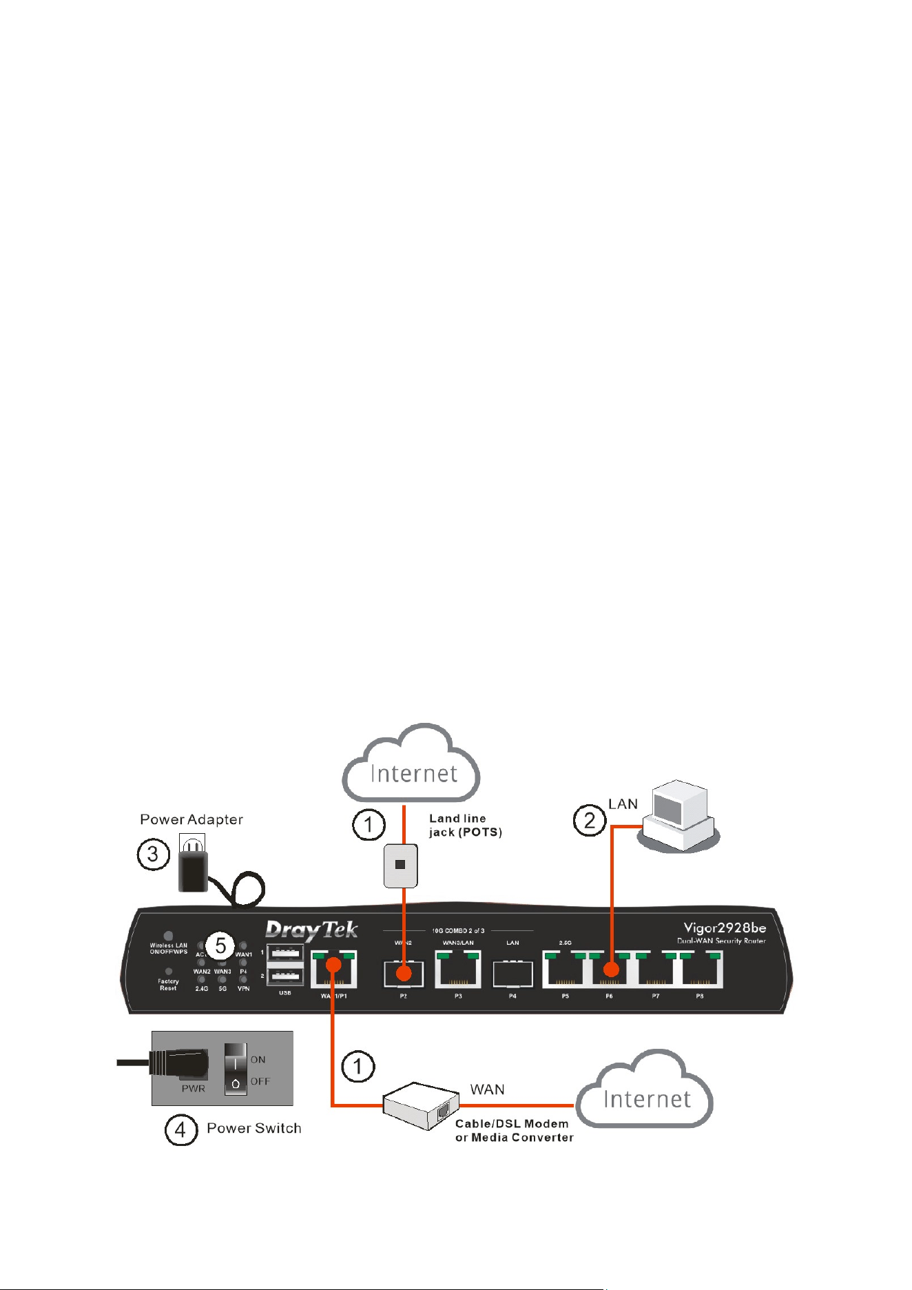
1. Connect the cable Modem/DSL Modem/Media Converter to any WAN port
of router with Ethernet cable (RJ-45).
2. Connect one end of an Ethernet cable (RJ-45) to one of the LAN ports of
the router and the other end of the cable (RJ-45) into the Ethernet port on
your computer.
3. Connect one end of the power cord to the power port of this device.
Connect the other end to the wall outlet of electricity.
4. Power on the device by pressing down the power switch on the rear panel.
5. The system starts to initiate. After completing the system test, the ACT LED
will light up and start blinking.
(For the detailed information of LED status, please refer to section 2. Panel
Explanation)
16
3
3
.
.
2
2
W
W
a
a
l
l
l
l
-
-
M
M
o
o
u
u
n
n
t
t
e
e
d
d
I
I
n
n
s
s
t
t
a
a
l
l
l
l
a
a
t
t
i
i
o
o
n
n
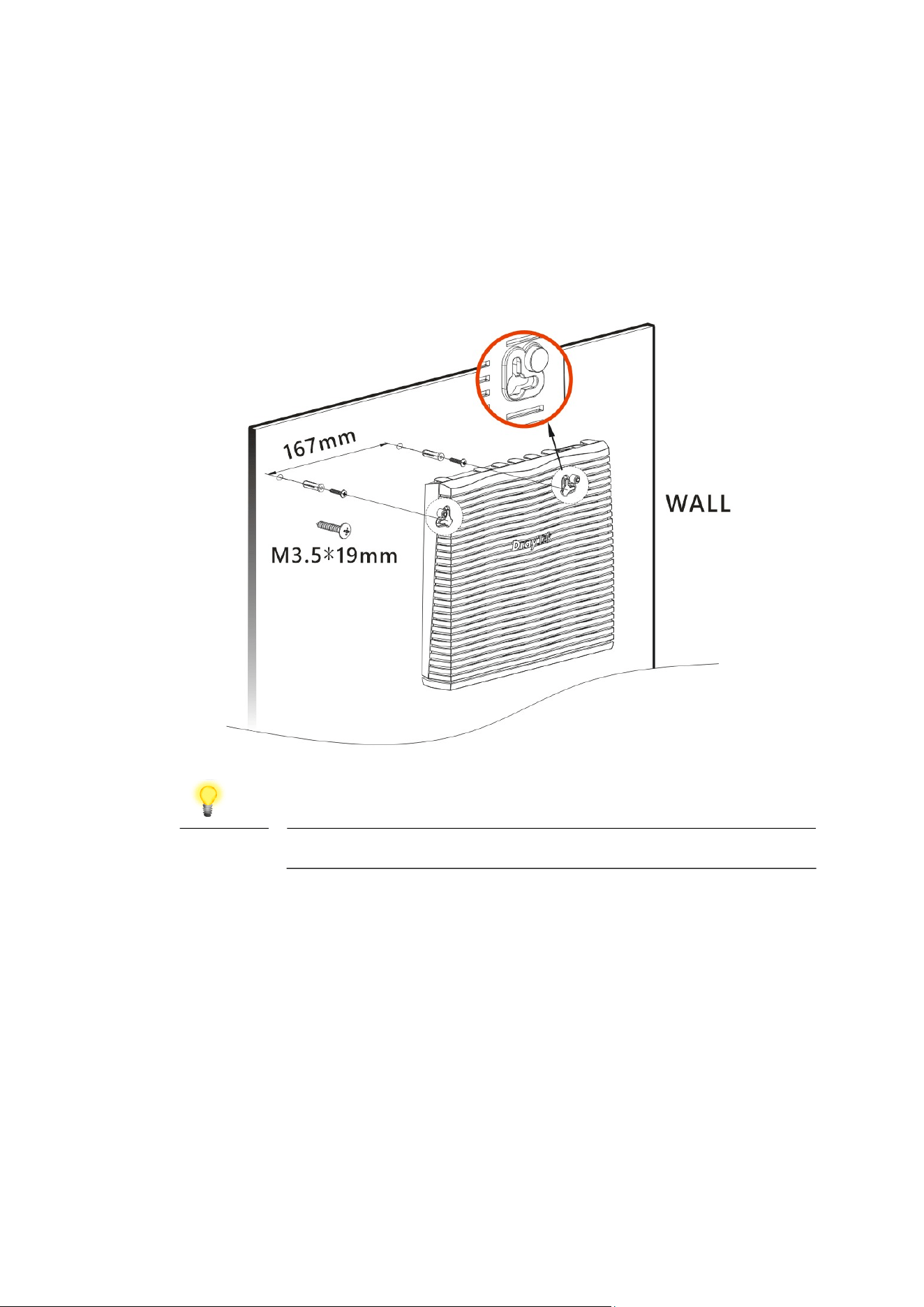
Vigor router has keyhole type mounting slots on the underside.
1. Drill two holes on the wall. The distance between the holes shall be 167mm.
2. Fit screws into the wall using the appropriate type of wall plug.
Note
The recommended drill diameter shall be 6.5mm (1/4”).
3. When you finished about procedure, the router has been mounted on the
wall firmly.
17
3
3
.
.
3
3
A
A
n
n
t
t
e
e
n
n
n
n
a
a
I
I
n
n
s
s
t
t
a
a
l
l
l
l
a
a
t
t
i
i
o
o
n
n
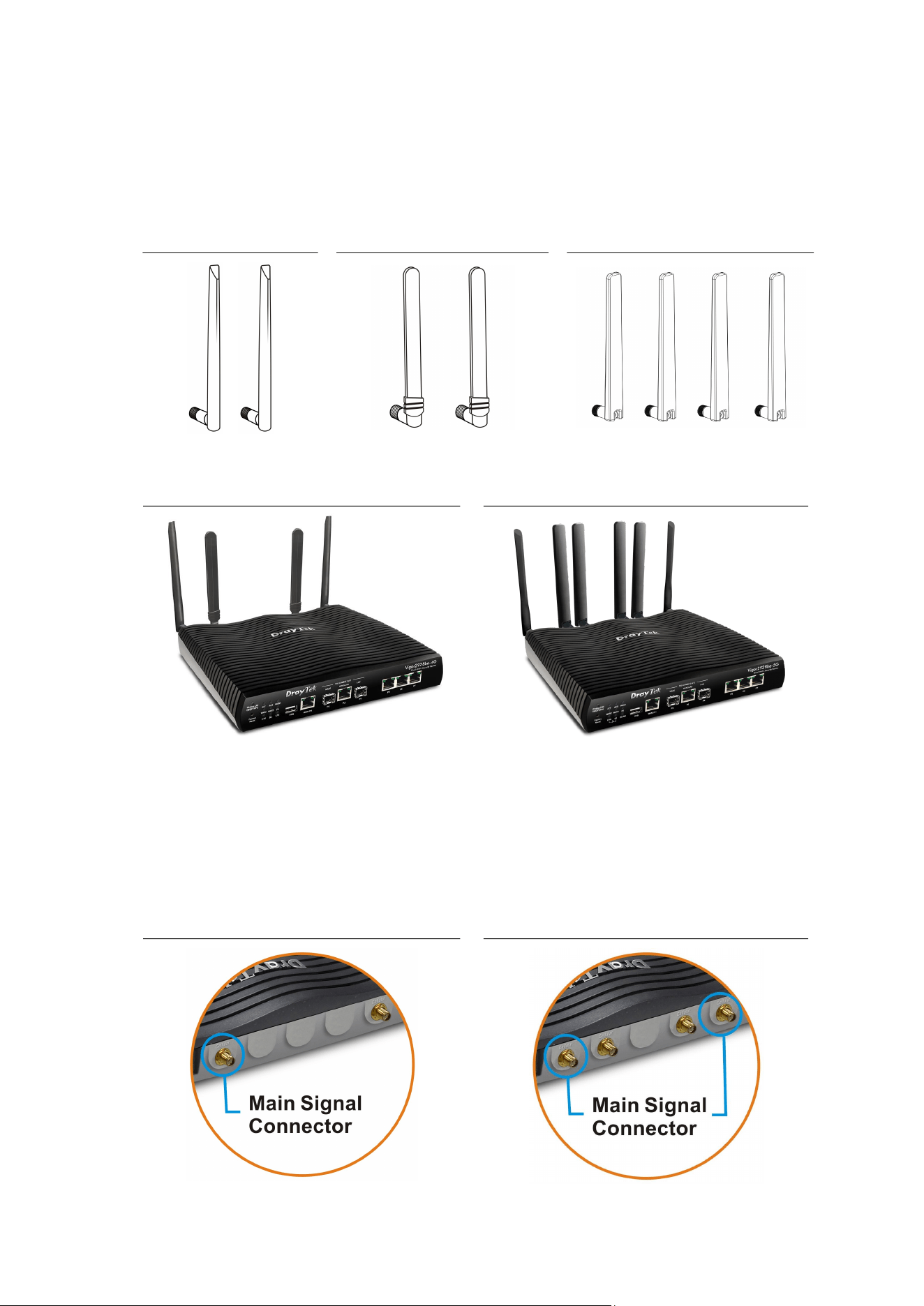
Antenna must be installed on Vigor router correctly to obtain the transmission
signal.
For be models
For 4G model
For 5G-NR model
The number of antenna used for 4G and 5G-NR models are different.
4G Model
5G-NR Model
For optimal wireless connectivity and data transmission performance, it is
recommended to connect all available antennas.
However, if you only need to install one or a pair of antennas to meet the needs
of certain environments (which may affect network performance), please refer
to the main signal connector diagram below for antenna installation.
4G Model
5G-NR Model
18
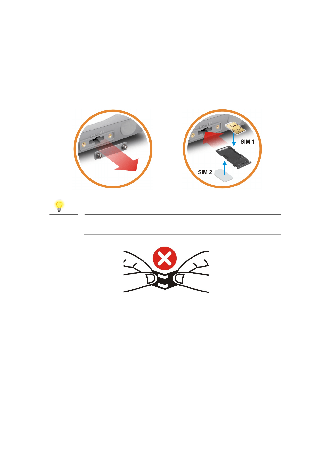
For installing the SIM card into the card slot,
(1) While installing the SIM card into the card slot, note that the back plate of
the SIM card slot must be removed first.
(2) Assemble the SIM1 and SIM2 with the SIM tray. Then insert the SIM tray into
the SIM card slot of the router.
Note
If you need to remove SIM1 or SIM2, carefully take them out of the
card slot without bending the SIM tray.
19
W
W
a
a
r
r
n
n
i
i
n
n
g
g
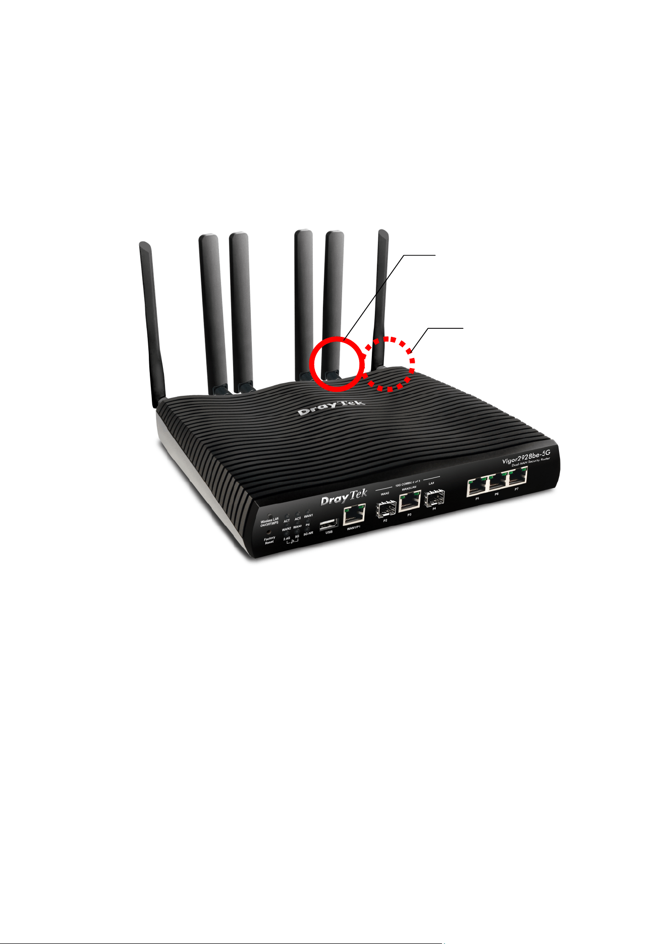
There are two types of antennas provided for Vigor2928be-5G, which must be
installed in different locations carefully and correctly. Wrong installation might
cause bad signal of wireless connection. Therefore, pay attention to the
installation of antennas by referring to the following illustration.
RP
-
SMA jack
for
WLAN Antenna
SMA jac
k for
LTE/NR
Antenna
20
4
4
.
.
S
S
o
o
f
f
t
t
w
w
a
a
r
r
e
e
C
C
o
o
n
n
f
f
i
i
g
g
u
u
r
r
a
a
t
t
i
i
o
o
n
n
To access Internet, please finish basic configuration after completing the
hardware installation.
The Quick Start Wizard is designed for you to easily set up your router for Internet
access. You can directly access the Quick Start Wizard via Web User Interface.
Make sure your PC connects to the router correctly.
Note
You may either simply set up your computer to get IP
dynamically from the router or set up the IP address of the
computer to be the same subnet as the default IP address of
Vigor router 192.168.1.1. For the detailed information, please refer
to - Trouble Shooting of the user’s guide.
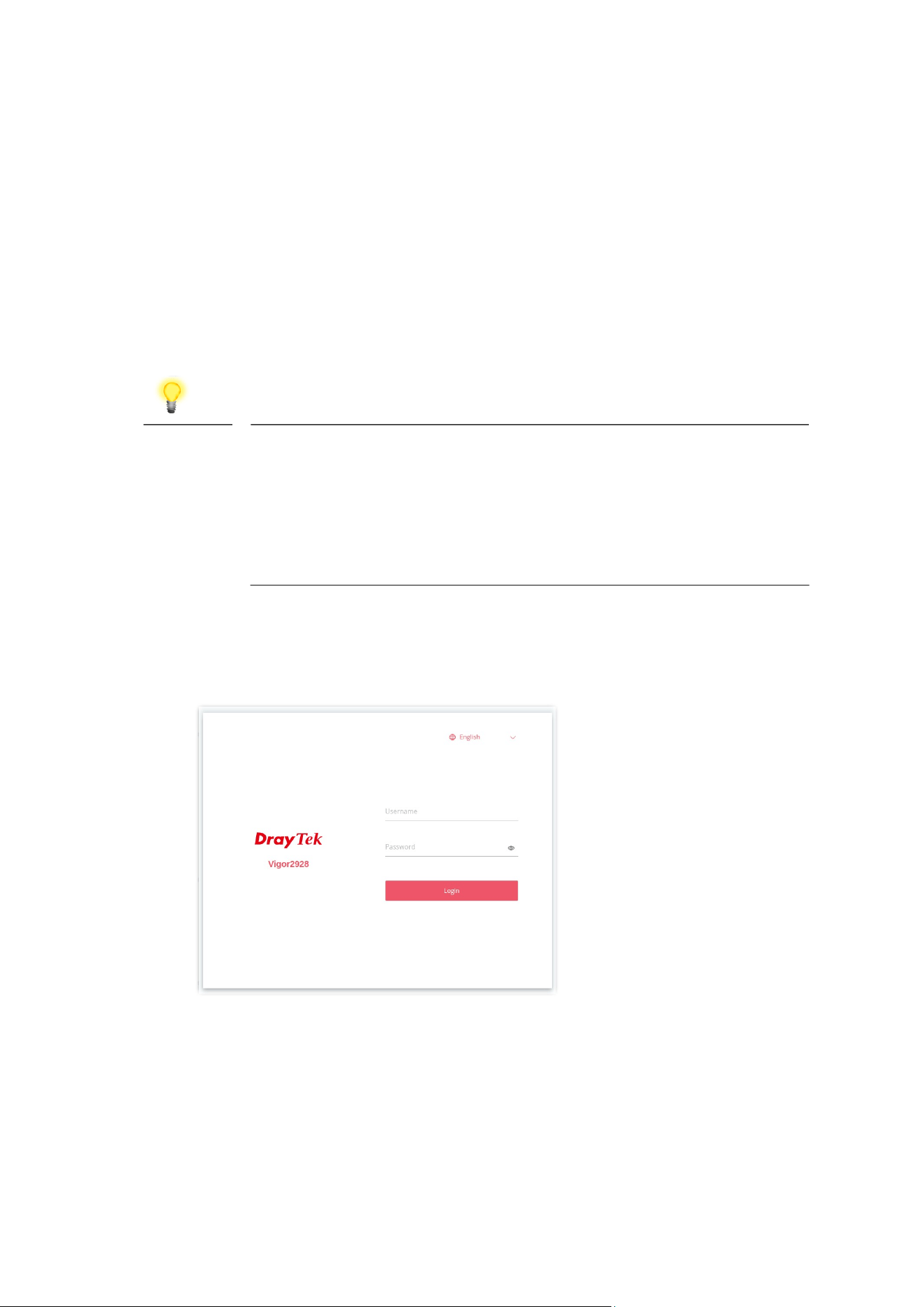
1. Open a web browser on your PC and type https://192.168.1.1. A pop-up
window will open to ask for username and password. Please enter
“admin/admin” as the Username/Password and click Login.
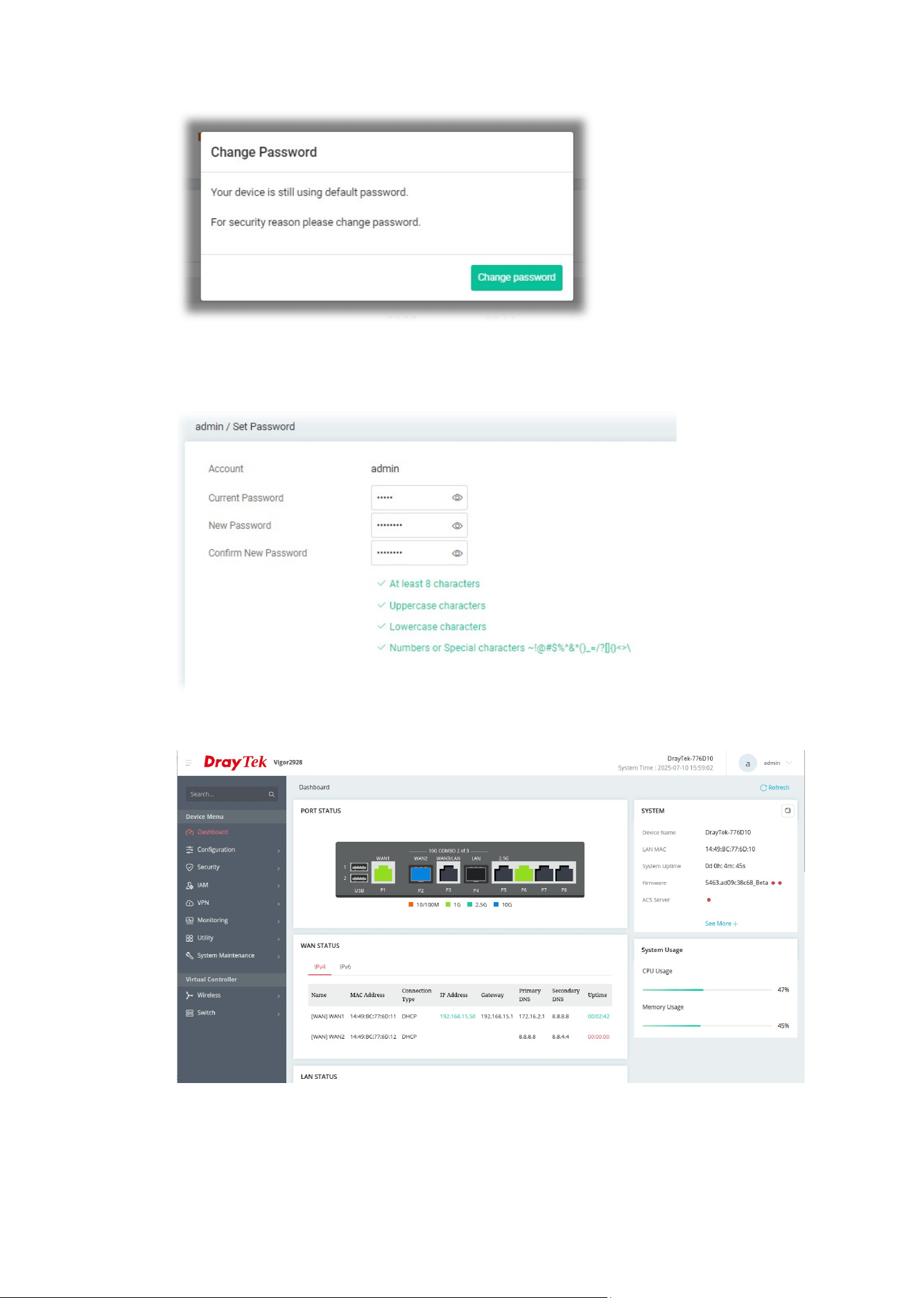
2. Next, the page will appear to guide you change the login password.
21
3. You MUST change the login password before accessing the web user
interface. Please set a new password for network security.
4. After clicking Apply, the Main Screen will pop up.

22
5
5
.
.
C
C
u
u
s
s
t
t
o
o
m
m
e
e
r
r
S
S
e
e
r
r
v
v
i
i
c
c
e
e
If the router cannot work correctly after trying many efforts, please contact your
dealer for further help right away. For any questions, please feel free to send
e-mail to sup[email protected].
B
B
e
e
a
a
R
R
e
e
g
g
i
i
s
s
t
t
e
e
r
r
e
e
d
d
O
O
w
w
n
n
e
e
r
r
Web registration is preferred. You can register your Vigor router via
https://myvigor.draytek.com.
F
F
i
i
r
r
m
m
w
w
a
a
r
r
e
e
&
&
T
T
o
o
o
o
l
l
s
s
U
U
p
p
d
d
a
a
t
t
e
e
s
s
Due to the continuous evolution of DrayTek technology, all routers will be
regularly upgraded. Please consult the DrayTek web site for more information
on newest firmware, tools and documents.
https://www.draytek.com