Installation and Set Up Guide
0620-D-00003 Rev 2
Page 2/4 1. Safety
(Sécurité)
Page 3/5 1.1 Safety Requirement –
Maximum Conductor Lengths /
Termination Requirements
(Exigences de sécurité – exigences
relatives à la longueur maximale et aux
terminaisons des conducteurs)
Page 6 1.2 Explanation of Graphical Symbols
on the Product
Page 6 2. Installation
Page 6 2.1 Mount the PSU
Page 6 2.2 Connections to the PSU
Page 7 2.2.1 Mains electrical supply input
connection
Page 7 2.2.2 Illuminator Cable / aux Power
Output Connections inside the PSU
Page 8 2.2.3 Customer Signal Cable
Connections inside the PSU
Page 9 2.2.4 Conduit Connection
(Mains electrical supply input)
Page 9 2.2.5 Cable Gland Plugs
Page 9 2.2.6 PSU Lid Attachment
Page 10 3. Specications Table
Page 12 4. Troubleshooting
Page 12 4.1 Warranty
Contents
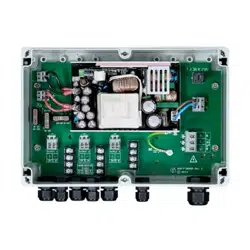
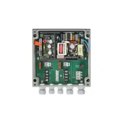
PSU-VAR2-100W-3
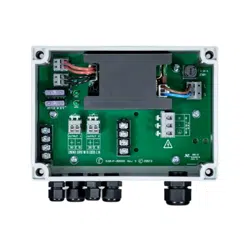
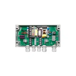
PSU-VAR2-20W-1
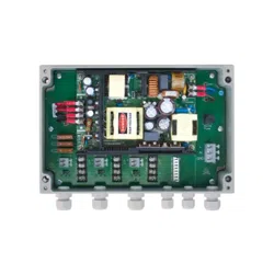
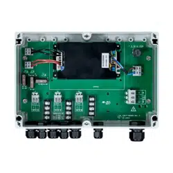
PSU-VAR2-150W-3
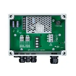
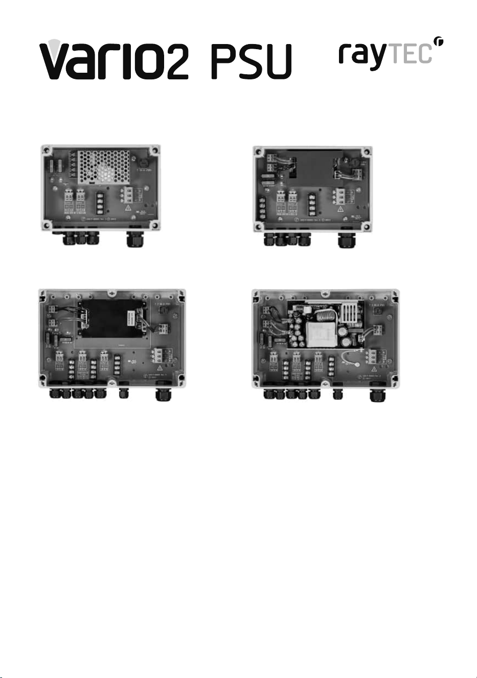
PSU-VAR2-50W-2
2
raytecled.com
Raytec Global Tel: +44 (0) 1670 520055
Americas Tel: +1 613 270 9990
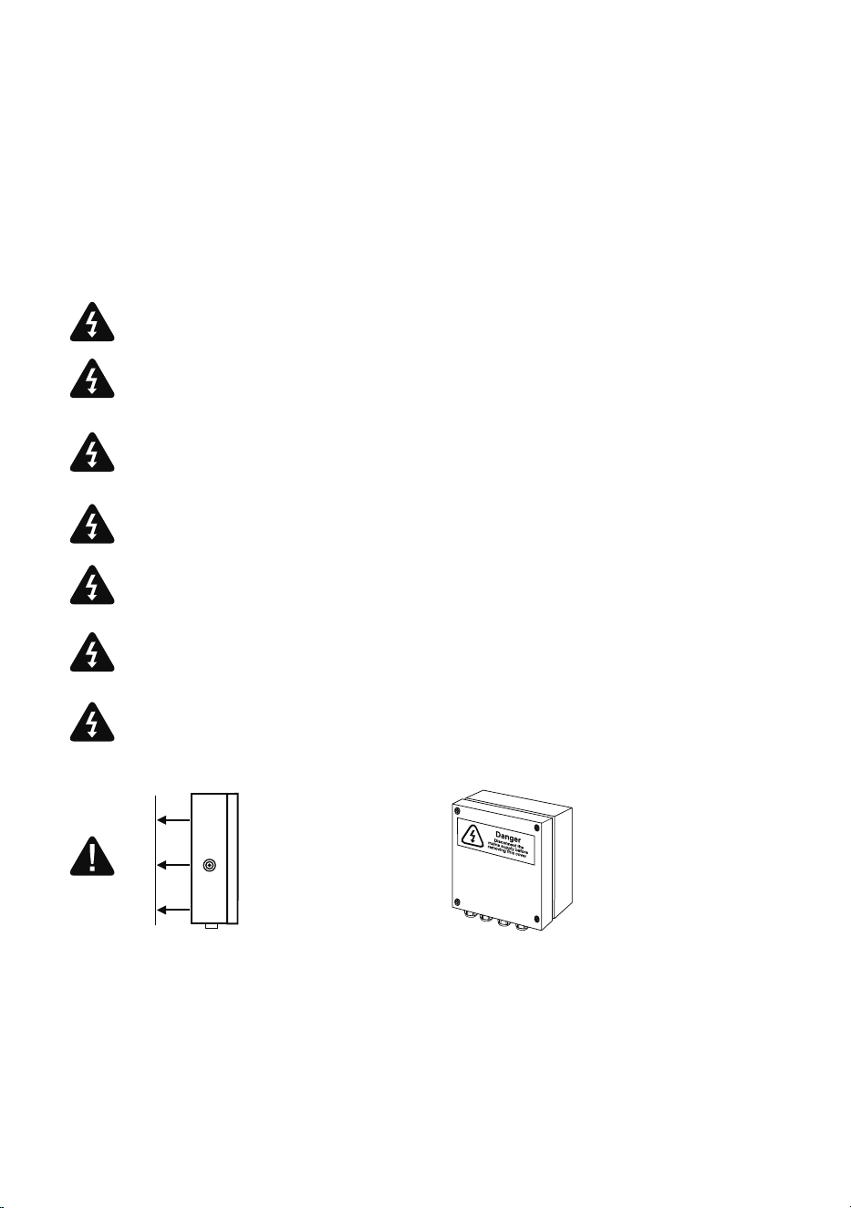
1. Safety
Safety related details in this installation guide are in English and
French language. If another language is required to understand
the instructions, please arrange for an appropriate translation
before proceeding
WARNINGS
Product Installation and maintenance must be by a suitably skilled
person / qualied electrician
Isolate mains electrical supply input before removing PSU lid / cover
Mains electrical supply input to PSU and all wiring to be in
accordance with the relevant regional codes and regulations
Maximum length limit and xing of conductors inside the PSU must
be complied with when connecting cables, to maintain the safety
approval of the product - see Fig 1.1
This equipment must be earthed
A suitably rated Residual Current Protective Device (RCD) must be
used in the Mains electrical supply input to this product
A suitable external current limiting / overcurrent protective device
must be used
The Mains electrical supply input to the PSU shall be tted with an all
pole disconnect device (device not included)
NOTE: Any connections made to the PSU must be tight and
secure and provide an environmental seal. All cable glands must
be tightened and a plug fitted if no cable installed
NOTE: This equipment is not suitable for use in locations where
children are likely to be present
Mount PSU
to flat surface
PSU must be
orientated in the
vertical plane with
cable glands at the
bottom, lid facing
outwards
3
raytecled.com
Raytec Global Tel: +44 (0) 1670 520055
Americas Tel: +1 613 270 9990
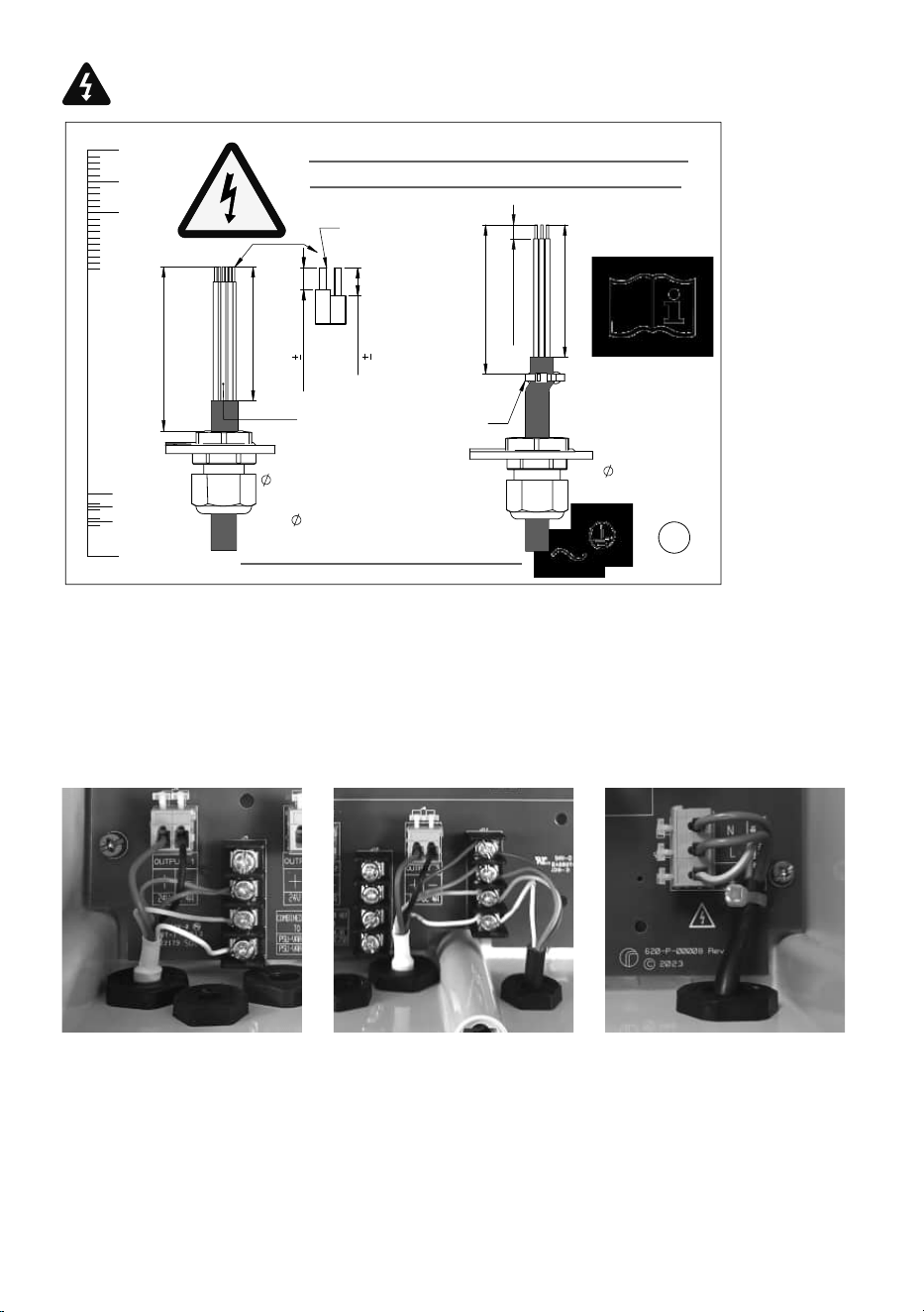
1.1 Safety Requirement –
Maximum Conductor Lengths / Termination Requirements
5.5
0.5mm
5.5 ± 0.5mm
CABLE TIE
60mm +0/-2 (2.36")
10mm
55mm +0/-2 (2.16")
55mm
8mm
2-4 OR 6
CONDUCTORS
0mm
5.5mm
L, N,
1:1 SCALE
REMOVE THIS CARD PRIOR TO USE
MAX 65mm +0/-2 (2.56")
MAX 65mm +0/-2 (2.56")
M20:
6-12mm
MAX 2.5sqmm/
14 AWG
FULL DETAILS
MAX CONDUCTOR LENGTHS INSIDE
UNIT / TERMINATION REQUIREMENTS
65mm
60mm
24V +VE/-VE
8
0.5mm
M16:
(ILLUMINATOR)
4-8mm
MAX 2.5sqmm/14 AWG
M12:
3-6.5mm
MAX 2.5sqmm /14 AWG
5.5
0.5mm
REVISION
ALL DIMENSIONS IN MM.
Tel: 01670 520055.
Fax: 01670 819760 .
DRAWN
CHK'D
UNLESS OTHERWISE SPECIFIED:
DIMENSIONS ARE IN MILLIMETERS
TOLERANCES: (LINEAR)
XXX +/- 0.5mm
XXX.X +/- 0.1mm
ANGULAR: +/- 0.5°
FINISH:
DEBUR AND
BREAK SHARP
EDGES
NAME
SIGNATURE
DATE
MATERIAL:
DO NOT SCALE DRAWING
TITLE:
DWG NO.
SCALE
1
A3
WEIGHT:
A
B
A
8
7
6
4
D
C
5
1
2
3
A
B
4
3
2
1
C
F
E
D
F
E
IF IN DOUBT ASK
8
7
6
5
2
SHEET
OF
SHEETS
D.Bloxham
Unit 3 Wansbeck Business Park,
Rotary Parkway.
Ashington.
Northumberland. NE63 8QW. UK.
SEE NOTES
SEE NOTES
SHEET
J
22/03/2024
VARIO PSU PAPER LABEL
620-M-00029
1:1
NOTE: The above Max conductor length and Termination requirements
must be complied with for the product safety approval to be maintained
NOTE: Where required conductors on the cable supplied with the
illuminator will need to be reduced in length
NOTE: Mains electrical supply input conductor colours in photo nominal -
dependent on installation supply
NOTE: All conductors fitted to be attached securely
Fig 1.1
4
raytecled.com
Raytec Global Tel: +44 (0) 1670 520055
Americas Tel: +1 613 270 9990
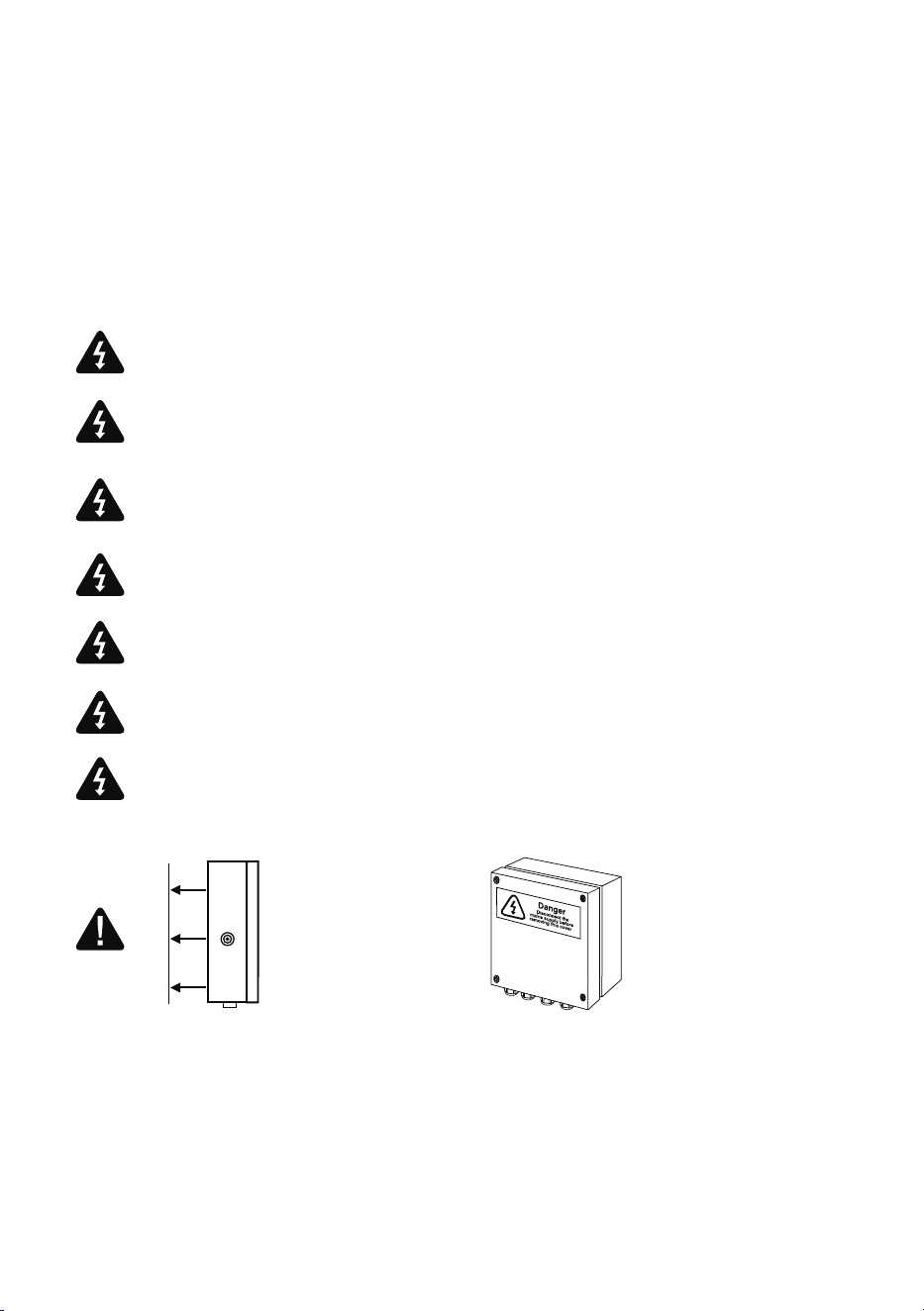
1. Sécurité
Les détails relatifs à la sécurité dans ce guide d’installation sont en anglais et
en français. Si une autre langue est requise pour comprendre les instructions,
veuillez prendre les dispositions nécessaires pour obtenir une traduction
appropriée avant de poursuivre
AVERTISSEMENTS
L’installation et l’entretien du produit doivent être effectués par une personne ou
un électricien qualifié.
Isoler l’alimentation électrique du secteur avant de retirer le couvercle du bloc
d’alimentation PSU.
L’alimentation électrique principale du produit et l’ensemble du câblage doivent
être conformes aux codes et aux réglementations en vigueur de chaque pays.
La longueur maximale et la fixation des conducteurs à l’intérieur du bloc
d’alimentation doivent être respectées lors de la connexion des câbles, afin de
maintenir la conformité du produit aux normes de sécurité - voir Fig 1.1.
Cet équipement doit être relié à la terre
Un dispositif de protection contre les courants résiduels (RCD) de valeur nominale
appropriée doit être utilisé pour la protection du produit.
Un dispositif externe approprié de limitation de courant/de protection contre les
surintensités doit être utilisé.
L’alimentation électrique du bloc d’alimentation PSU doit être équipée d’un
dispositif de coupure omnipolaire (dispositif non inclus).
REMARQUE : Toutes les connexions au bloc d’alimentation doivent être étanches.
Tous les presse-étoupes doivent être serrés et un bouchon doit être installé si
aucun câble n’est installé.
REMARQUE : Cet équipement ne convient pas à une utilisation dans des endroits où
des enfants sont susceptibles d’être présents.
Fixer le bloc
d’alimentation sur
une surface plane
Le bloc d’alimentation
doit être orienté dans
le plan vertical, les
presse-étoupes en
bas, le couvercle
tourné vers l’extérieur.
5
raytecled.com
Raytec Global Tel: +44 (0) 1670 520055
Americas Tel: +1 613 270 9990
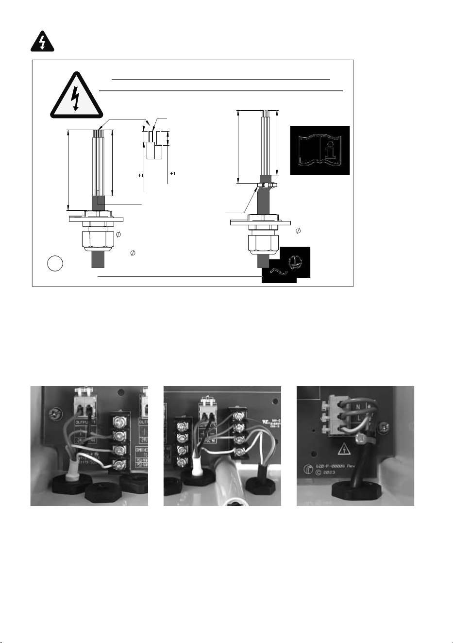
1.1 Exigences de sécurité – exigences relatives à la longueur maximale et aux
terminaisons des conducteurs
5.5
0.5mm
ATTACHE DE
CÂBLE
60mm +0/-2 (2.36")
55mm +0/-2 (2.16")
2-4 OU 6
CONDUCTEURS
L, N,
UTILISER L'ÉCHELLE AU VERSO
RETIREZ CETTE CARTE AVANT UTILISATION
MAX 65mm +0/-2 (2.56")
MAX 65mm +0/-2 (2.56")
M20:
6-12mm
MAX 2.5sqmm/
14 AWG
RENSEIGNEMENTS
COMPLETS
LONGUEURS MAXIMALES DES CONDUCTEURS À
L'INTÉRIEUR DU BOÎTIER/ EXIGENCES DE TERMINAISON
24V +VE/-VE
8
0.5mm
M16:
(PROJECTEUR)
4-8mm
MAX 2.5sqmm/14 AWG
M12:
3-6.5mm
MAX 2.5sqmm /14 AWG
5.5
0.5mm
REVISION
ALL DIMENSIONS IN MM.
Tel: 01670 520055.
Fax: 01670 819760 .
DRAWN
CHK'D
UNLESS OTHERWISE SPECIFIED:
DIMENSIONS ARE IN MILLIMETERS
TOLERANCES: (LINEAR)
XXX +/- 0.5mm
XXX.X +/- 0.1mm
ANGULAR: +/- 0.5°
FINISH:
DEBUR AND
BREAK SHARP
EDGES
NAME
SIGNATURE
DATE
MATERIAL:
DO NOT SCALE DRAWING
TITLE:
DWG NO.
SCALE
2
A3
WEIGHT:
A
B
A
8
7
6
4
D
C
5
1
2
3
A
B
4
3
2
1
C
F
E
D
F
E
IF IN DOUBT ASK
8
7
6
5
2
SHEET
OF
SHEETS
D.Bloxham
Unit 3 Wansbeck Business Park,
Rotary Parkway.
Ashington.
Northumberland. NE63 8QW. UK.
SEE NOTES
SEE NOTES
SHEET
J
22/03/2024
VARIO PSU PAPER LABEL
620-M-00029
1:1
REMARQUE : Les exigences relatives à la longueur maximale et aux terminaisons des
conducteurs ci-dessus doivent être respectées pour que l’approbation de sécurité du produit
soit maintenue
REMARQUE : Au besoin, la longueur des conducteurs du câble fourni avec l’illuminateur
devra être réduite
REMARQUE : Couleur des conducteurs d’entrée au réseau électrique en photo (nominal) –
selon l’installation
REMARQUE : Tous les conducteurs doivent être fixés solidement
Figure 1,1
6
raytecled.com
Raytec Global Tel: +44 (0) 1670 520055
Americas Tel: +1 613 270 9990
1.2 Explanation of Graphical Symbols on the Product
AC Voltage
(Tension alternative)
Class 1 Insulation;
Protective Earth
(Isolation de classe 1 ;
terre de protection)
WEEE (Electronic Waste
to be re-cycled)
2. Installation
2.1 Mount the PSU
• Mount PSU to at surface
(Monter PSU sur une surface plane)
• PSU must be orientated in the vertical plane with cable glands at the bottom, lid
facing outwards
(Le bloc d’alimentation doit être orienté dans le plan vertical, les presse-étoupes en bas,
le couvercle tourné vers l’extérieur)
• See illustration in section 1
(Voir l’illustration dans la section 1)
• A screw pack is provided with the PSU
• 3.5mm x 40mm Pozi-Pan Screw – Stainless Steel (A2) Qty 4
• Before mounting the PSU the customer/ installer must ensure that the mounting
material is suitable and the correct xings are used to securely attach the PSU
(Avant de monter le bloc d’alimentation, le client ou l’installateur doit s’assurer que le matériel
de montage et les fixations sont appropriés pour fixer solidement le bloc d’alimentation)
• Product packaging base has holes present to act as a drilling template
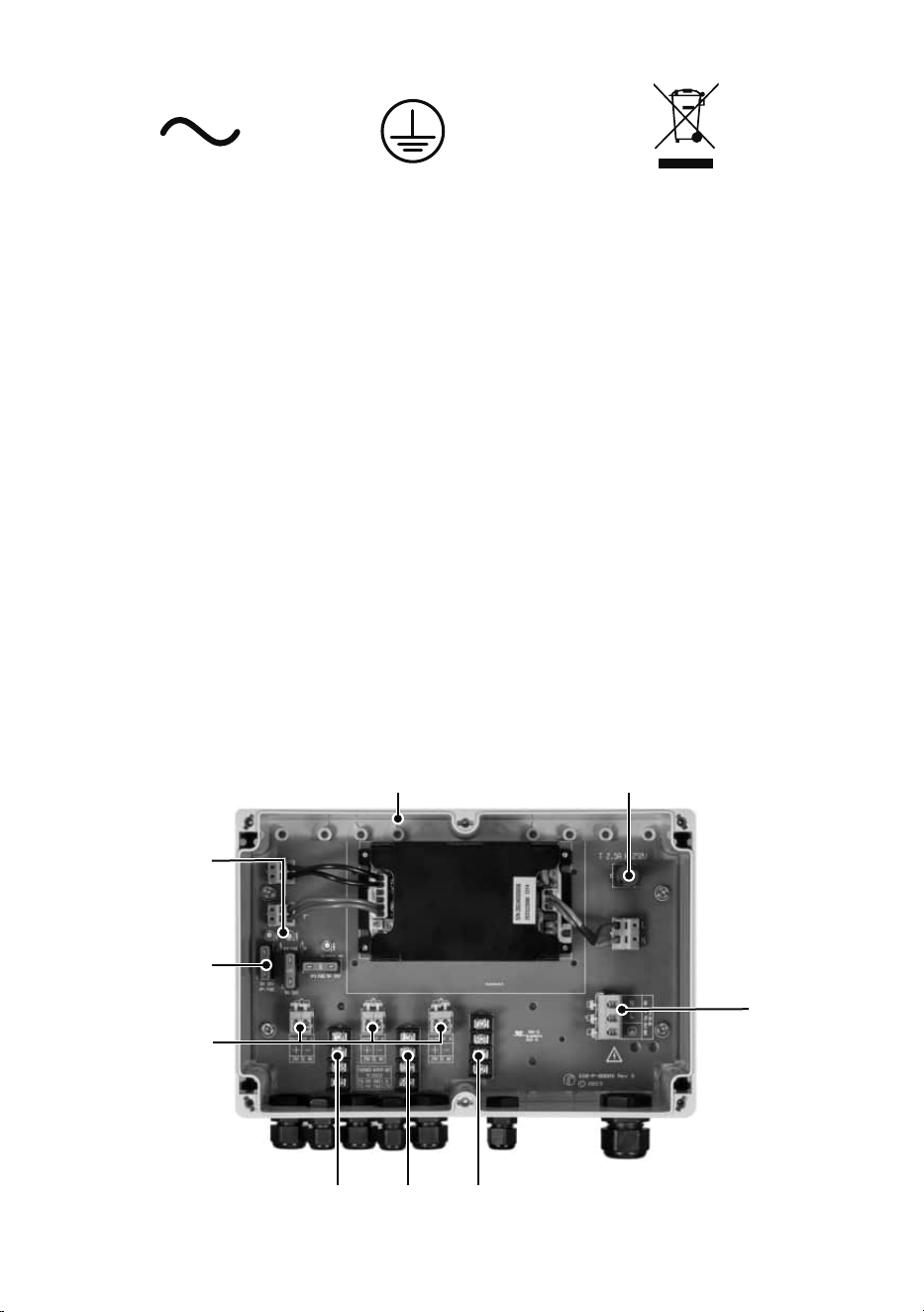
2.2 Connections to the PSU
Example PSU-VAR2-100W-3
Mains electrical
supply input
Automative
blade output
fuses
Power Output
Status Indicator
LEDs
Lightweight UV stable
polycarbonate enclosure
Slowblow
input fuse
Multiple wiring terminals
(inc. telemetry input and photocell following output)
Multiple
Illuminator
Power Outputs
7
raytecled.com
Raytec Global Tel: +44 (0) 1670 520055
Americas Tel: +1 613 270 9990
2.2.1 Mains Electrical Supply Input Connection
(Raccord d’entrée au réseau électrique)
All cable conductors must not exceed the maximum length specied and be attached
securely to maintain the safety of the product – see Safety section / Fig 1.1
(Aucun conducteur de câble ne doit dépasser la longueur maximale indiquée et tous les conducteurs doivent
être solidement xés pour assurer la sécurité du produit – voir la section Sécurité ou la Figure 1.1)
Cable Gland: M20 Gland Nut A/F (Across Flats): 24mm
Cable outer diameter range: 6mm to 12mm (0.24” to 0.47”)
Max conductor size: 2.5mm
2
/ 14 AWG
Earth conductor length from cable sheath to be equal to length of L and N conductors from
cable sheath
Connect Mains electrical supply input power using terminal block provided. Depress lever on
relevant terminal, insert wire and release lever. Ensure connection is secure
Secure the Mains electrical supply input cable to the PCB by tightening the cable tie around
it. The max length requirement between the cable tie and the conductor ends must be
complied with to maintain the safety approval of the product - See Fig 1.1
Cut out and discard the excess cable tie
All connections, including cable glands to be checked as tight and secure
(Tous les raccords, y compris les presse-étoupes, doivent être vérifiés et fixés solidement)
2.2.2 Illuminator Cable / aux Power Output Connections
(Raccords de sortie d’alimentation auxiliaire ou de câble d’illuminateur)
All cable conductors must not exceed the maximum length specied and be attached
securely to maintain the safety of the product – see Safety section / Fig 1.1
(Aucun conducteur de câble ne doit dépasser la longueur maximale indiquée et tous les conducteurs doivent
être solidement xés pour assurer la sécurité du produit – voir la section Sécurité ou la Figure 1.1)
Cable Gland: M16 Gland Nut A/F (Across Flats): 19mm
Cable outer diameter range: 4mm to 8mm (0.16” to 0.31”)
Max conductor size: 2.5mm2 / 14 AWG
NOTE: For the VARIO2 and VARIO2 POE Premium illuminators to come on automatically via
the Photocell the telemetry wires (orange and purple conductors in illuminator cable) must
be joined /shorted
NOTE: Some other Illuminators may respond differently to telemetry and photocell functions,
please check the relevant illuminator Installation Guide
8
raytecled.com
Raytec Global Tel: +44 (0) 1670 520055
Americas Tel: +1 613 270 9990
The illuminator cable has 6 colour coded conductors
Red and Black Conductors (Illuminator Power):
Connect 24V DC power using power output connectors
• Red conductor connected to +ve terminal on the PSU illuminator output connector 24V DC
• Black conductor connected to -ve terminal on the PSU illuminator output connector 24V DC
Depress lever on the relevant connector terminal, insert wire and release lever. Ensure
connection is secure.
Orange and Purple Wires (Telemetry Input):
Allows the VARIO2 and VARIO2 POE Premium illuminators to be turned on and off from
a separate external Volt free/dry contact; TTL input. Or they need to be electrically joined
together / short circuited for the illuminators to come on automatically via the photocell.
Please see the illuminator installation guide
White and Yellow Wires (Photocell Following Contact):
Allows the photocell state output (Daylight or darkness) from the illuminator to be used as a
signal if required (Volt free output; Non polarity sensitive)
NOTE: Some other Illuminators may respond differently to telemetry and photocell functions,
please check the relevant illuminator installation guide
Any remaining unused control wires inside the PSU should be securely connected to the 4
way screw terminal block
PSU-VAR2-20W-1 spare 8W aux 24V DC power only output - Output 2:
(PSU-VAR2-20W-1 sortie auxiliaire de 8W 24V DC alimentation uniquement - Sortie 2)
The above conductor length requirements and 24V DC connector details apply
(Les exigences relatives à la longueur des conducteurs et les détails des connecteurs 24V DC ci-dessus
s’appliquent)
All connections, including cable glands to be checked as tight and secure
(Tous les raccords, y compris les presse-étoupes, doivent être vérifiés et fixés solidement)
2.2.3 Customer Signal Cable Connections
(Raccords du câble de signal du client)
All cable conductors must not exceed the maximum length specied and be attached
securely to maintain the safety of the product – see Safety section / Fig 1.1
(Aucun conducteur de câble ne doit dépasser la longueur maximale indiquée et tous les conducteurs doivent
être solidement xés pour assurer la sécurité du produit – voir la section Sécurité ou la Figure 1.1)
Cable Gland: M12 Gland Nut A/F (Across Flats): 15mm
Cable outer diameter range: 3mm to 6.5mm (0.12” to 0.25”)
Conductor size: 0.34mm2 to 2.5mm2 / 22AWG to 14AWG
Allows the customer to connect to the illuminator signal wires to turn the illuminator(s) On/Off
separately and use the photocell state (Day/Night) signal from the illuminator – Refer to illuminator
Installation Guide for full operation details
All connections, including cable glands to be checked as tight and secure
(Tous les raccords, y compris les presse-étoupes, doivent être vériés et xés solidement)
9
raytecled.com
Raytec Global Tel: +44 (0) 1670 520055
Americas Tel: +1 613 270 9990
2.2.4 Conduit Connection (Mains electrical supply input)
(Raccord de conduit (entrée au réseau électrique))
If a conduit connection is used instead of the M20 gland for the Mains electrical
supply input cable, it is the installers responsibility to ensure the following:
(Si un raccord de conduit est utilisé au lieu d’un presse-étoupe M20 pour le câble d’entrée au réseau
électrique, les éléments suivants tombent sous la responsabilité de l’installateur.)
-
IP66 / Environmental seal rating to be maintained between the conduit and the
PSU enclosure and at the other end of the conduit
(L’indice de protection IP66 relatif à l’étanchéité pour l’environnement doit être maintenu entre
le conduit et le boîtier du bloc d’alimentation ainsi qu’a l’autre extrémité du conduit)
-
If Metal conduit being used, it must be earthed in accordance with local
regulations or code
(Si un conduit métallique est utilisé, il doit être mis à la terre conformément aux
réglementations ou au code locaux)
All connections to be checked as tight and secure to the manufacturer’s recommendations
(Tous les raccords doivent être vériés et sécurisés conformément aux recommandations du fabricant)
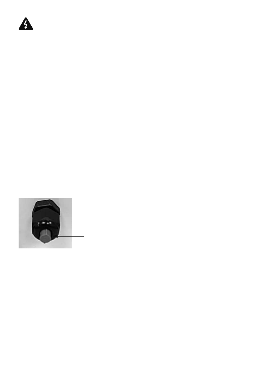
2.2.5 Cable Gland Plugs
The VARIO2 PSUs have cable gland plugs tted to a number of the cable glands. The plugs
are present to maintain the environmental sealing of the unit if the gland is not in use
If the installer is required to re-install these plugs for any reason the following assembly
process is required
•
Mount the plug into the cable gland as shown below
•
Tighten the cable gland whilst maintaining the level of the protrusion of the plug from the
front of the gland
All connections, including cable glands to be checked as tight and secure
(Tous les raccords, y compris les presse-étoupes, doivent être vériés et xés solidement)
2.2.6
PSU Lid Attachment
(Fixation du couvercle du bloc d’alimentation)
Make sure the ‘Maximum Conductor Length’ detail card is removed from inside the unit
before re-tting the PSU lid
(Assurez-vous que la carte des informations détaillées sur la « Longueur maximale du conducteur »
est retirée de l’intérieur de l’unité avant de remettre le couvercle du bloc d’alimentation en place)
Lid xing screws to be tightened, so the lid is tight and secure and the unit is
environmentally sealed
(Les vis de xation du couvercle doivent être serrées de façon à ce que le couvercle soit xé de
manière sécuritaire et que le bloc soit étanche en respect de l’environnement)
NOTE: Make sure the plug is positioned within the gland,
so it is protruding with the bottom of its side ribs located
against the front of the main body of the gland
(M12 glands - Locate the gland nut rst)
(M16 glands - Tighten the gland nut slightly rst)
10
raytecled.com
Raytec Global Tel: +44 (0) 1670 520055
Americas Tel: +1 613 270 9990
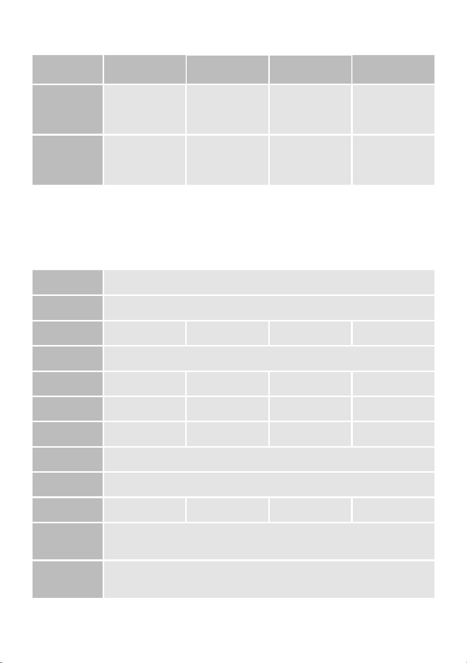
3. Specications Table
Illuminator
Congurations
PSU-VAR2-20W-1
(small)
PSU-VAR2-50W-2
(medium)
PSU-VAR2-100W-3
(large)
PSU-VAR2-150W-3
(x-large)
Illuminators
1 x VARIO 2 series
Plus aux output (max 8w)
up to 2 x VARIO 4 series
up to 2 x VARIO 6 series
1 x VARIO 8 series
up to 3 x VARIO 4 series
up to 3 x VARIO 6 series
up to 2 x VARIO 8 series
up to
3 x VARIO 8 series
Other Illuminator
options
up to 4 x VARIO 2 series *
up to 8 x VARIO 2 series *
up to 4 x VARIO 4 series *
up to 4 x VARIO 6 series *
1 x VARIO 16 series
up to 6 x VARIO 4 series*
up to 6 x VARIO 6 series *
1 x VARIO 16 series
Please note: for medium, large and x-large PSUs powering an increased number of VARIO illuminators, the total power
of the illuminators must not exceed the PSU max output
(Remarque : pour les blocs d’alimentation moyens, grands et très grands alimentant un nombre accru d’illuminateurs VARIO, la puissance
totale des illuminateurs ne doit pas dépasser la puissance de sortie maximale du bloc d’alimentation)
*illuminator output cables may also need to be commoned together to suit the number of available glands.
Mixed model sizes of VARIO illuminators can be powered from the same PSU
e.g. PSU-VAR2-50W-2 can also run 2 x VARIO 2 series and 1 x VARIO 4 series.
Input 100-230V AC +/-10%
Frequency 50-60Hz
In Rush 45A (230V AC) 100A (230V AC) 150A (230V AC) 80A (230V AC)
Input Fuse Type 20mm, slow blow, user replaceable
Input Fuse Rating 1A 2.5A 2.5A 2.5A
Max PSU
Consumption
25W 57W 110W 170W
Max PSU Output 20W 50W 100W 150W
Output Voltage 24V DC
Output Fuse Type Automotive, blade, user replaceable
Output Fuse Rating 3A 3A 5A 5A
Operating and
storage Temperature
-40 to +50°C (-40 to 122°F)
Telemetry and
Photocell Following
output wiring
Quick and easy wiring for VARIO input and output connections -
4-way robust terminal for telemetry input and photocell following output
11
raytecled.com
Raytec Global Tel: +44 (0) 1670 520055
Americas Tel: +1 613 270 9990
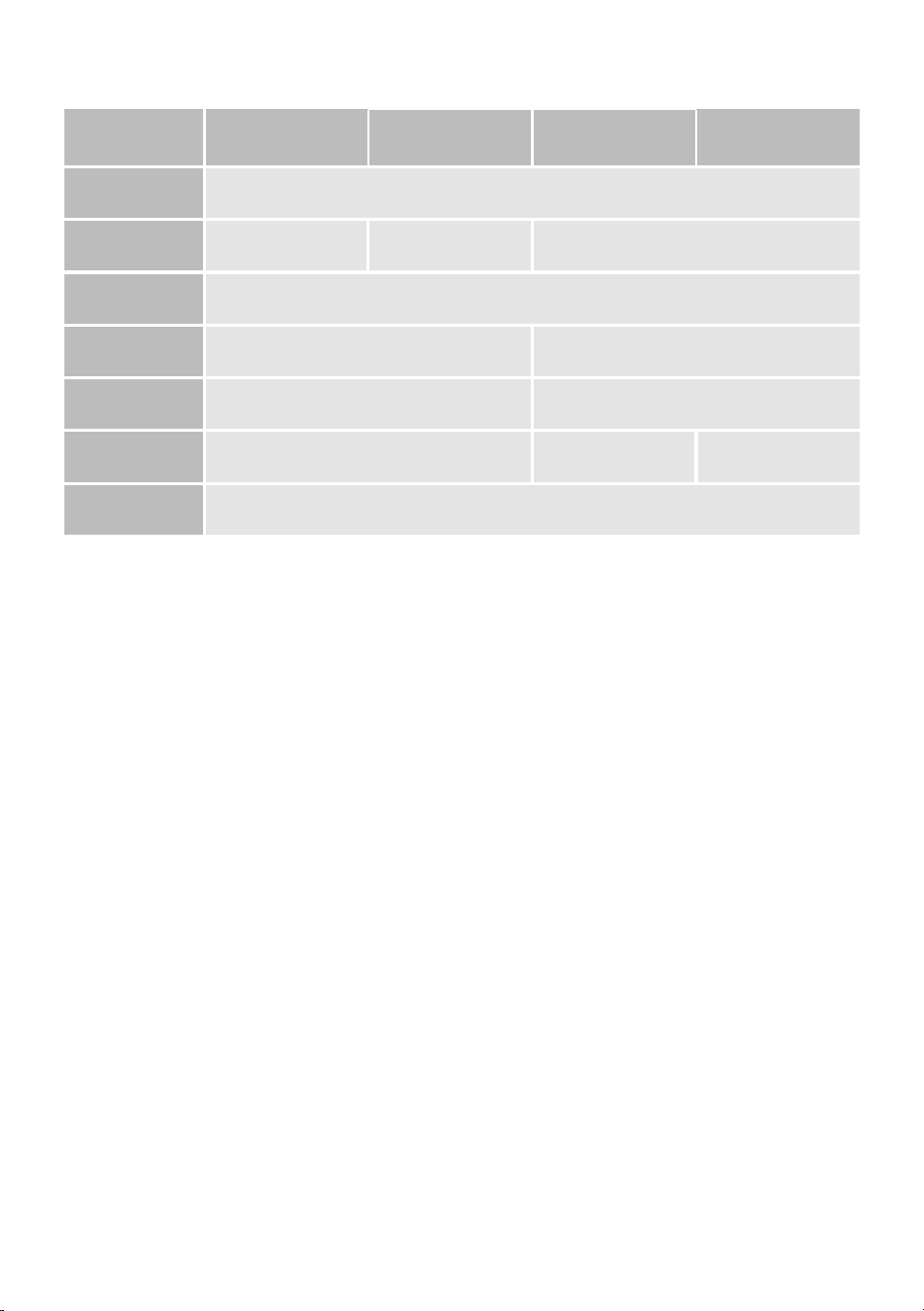
Illuminator
Congurations
PSU-VAR2-20W-1
(small)
PSU-VAR2-50W-2
(medium)
PSU-VAR2-100W-3
(large)
PSU-VAR2-150W-3
(x-large)
Status LEDs Status LEDs to indicate status of each output
Glands
1x M20, 2x M16,
1x M12, IP66
1x M20, 2x M16,
2x M12, IP66
1xM20, 3x M16, 3x M12, IP66
Enclosure
construction
Lightweight UV stable polycarbonate with integrated sealing gasket
PSU Dimensions
(excluding glands)
180 x 130 x 60 mm (7.1 x 5.1 x 2.4 inch) 244 x 164 x 90 mm (9.6 x 6.5 x 3.5 inch)
Mounting hole
positions
163mm x 113mm (6.44” x 4.47”) 229mm x 130mm (9.02” x 5.12”)
Weight 0.65kg (1.44lb) 1.24kg (2.74lb) 1.52kg (3.36lb)
IP Rating IP66

12
raytecled.com
Raytec Global Tel: +44 (0) 1670 520055
Americas Tel: +1 613 270 9990
4. Troubleshooting
Ensure all investigations and tests are undertaken by a skilled person
(Toutes les investigations et tous les tests doivent être effectués par une personne qualifiée)
Ensure safe working practices are followed at all times
(Les pratiques de travail sûres doivent être respectées à tout moment)
• Check that the output status LED indicators in the PSU for the power out connector(s)
are illuminated (if not check the output fuses. Replace the fuses as necessary.)
If the output LEDs in the PSU are illuminated check that 24V DC is present on the output
power terminals
• Ensure the telemetry wires (orange and purple conductors in the illuminator cable) are
joined /shorted or closed contact input (zero volt) is applied (VARIO2 and VARIO2 POE
Premium products)
• Check photocell is working. Cover illuminator photocell fully, illuminator should turn on
NOTE: Some other illuminators may respond differently to telemetry and photocell
functions, please check the relevant illuminator Installation Guide
• If longer cables used, ensure sufcient voltage is provided to allow for drops across
the cable
For further fault nding refer to the Illuminator Installation Guide.
If the problem persists, please call Raytec for further assistance. Note down:
• Nature of the problem
• Model and serial number of PSU and illuminator
4.1 Warranty
All VARIO2 PSUs are provided with a 5-year warranty. Contact Raytec for more details.
Please detail the model and serial number of the PSU and illuminators you are using

13
raytecled.com
Raytec Global Tel: +44 (0) 1670 520055
Americas Tel: +1 613 270 9990

14
raytecled.com
Raytec Global Tel: +44 (0) 1670 520055
Americas Tel: +1 613 270 9990

15
raytecled.com
Raytec Global Tel: +44 (0) 1670 520055
Americas Tel: +1 613 270 9990

Raytec Global (excluding Americas)
Tel: +44 (0) 1670 520055
Raytec Ltd.
Unit 15 Wansbeck Business Park, Rotary Parkway
Ashington, Northumberland, NE63 8QW, United Kingdom
DISCLAIMER: The information provided in this document was accurate at the time of its creation.
However, due to the evolving nature of our products and continuous improvements, there may be
changes or updates that occur after its publication. For the most current and detailed information
about our products, please contact our sales team at [email protected]
CLAUSE DE NON-RESPONSABILITÉ : Les informations fournies dans ce document étaient exactes au moment de sa
création. Toutefois, en raison de la nature évolutive de nos produits et des améliorations continues, des changements
ou des mises à jour peuvent intervenir après sa publication. Pour obtenir les informations les plus récentes et les plus
détaillées sur nos produits, veuillez contacter notre équipe commerciale à l’adresse suivante : sales@raytecled.com
Raytec Americas
Tel: +1 613 270 9990
Raytec Systems Inc.
800-300 Terry Fox Drive, Ottawa, Ontario
2K 0E3, Canada
raytecled.com