Operating / Safety Instructions
Consignes d’utilisation / de sécurité
Instrucciones de funcionamiento y seguridad
Call Toll Free for Consumer Information & Service Locations
Pour obtenir des informations et les adresses de nos centres de service après-vente, appelez ce numéro gratuit
Llame gratis para obtener información para el consumidor y ubicaciones de servicio
For English Version
See page 2
●
Version française
Voir page 23
●
Versión en español
Ver la página 44
IMPORTANT
Read Before Using
●
IMPORTANT
Lire avant usage
●
IMPORTANTE
Leer antes de usar
1-877-BOSCH99 (1-877-267-2499) www.boschtools.com
GLF55-25
16099221WG GLF55-25 OSI Final 20250228.indd 116099221WG GLF55-25 OSI Final 20250228.indd 1 2/28/2025 8:49:23 AM2/28/2025 8:49:23 AM
2
Safety Symbols
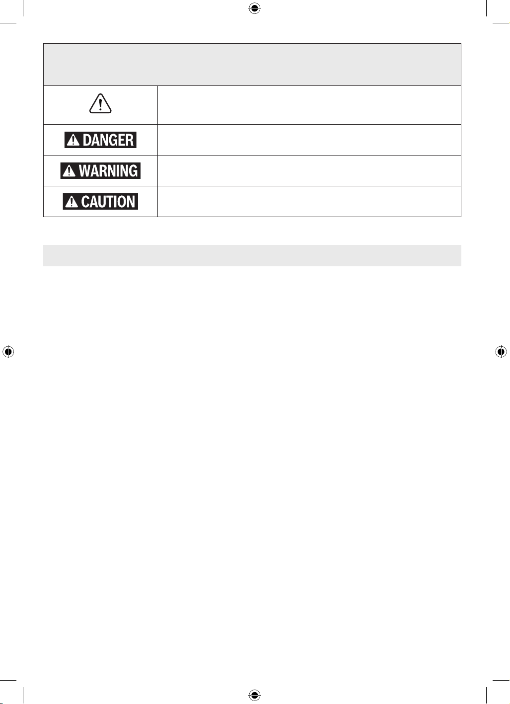
The definitions below describe the level of severity for each signal word.
Please read the manual and pay attention to these symbols.
This is the safety alert symbol. It is used to alert you to potential
personal injury hazards. Obey all safety messages that follow this
symbol to avoid possible injury or death.
DANGER indicates a hazardous situation which, if not avoided, will
result in death or serious injury.
WARNING indicates a hazardous situation which, if not avoided,
could result in death or serious injury.
CAUTION indicates a hazardous situation which, if not avoided,
could result in minor or moderate injury.
Table of Contents
General Power Tool Safety Warnings ......3
Safety Instructions for Routers...........4
Additional Safety Warnings .............5
Disposal.........................6
Intended Use ........................6
Symbols............................7
Specications .......................8
Getting to Know Your GLF55-25 Trim
Router ..........................9
Assembly and Adjustments.............11
Router Bits ......................11
Replacing the Collet ...............12
Installing and Removing the Trim
Router in the Fixed Base ......... 12
Installing Dust Extraction Hood
(GLF001) (optional accessory) .... 13
Installing the Template Guide
(optional accessory) ............13
Assembling the Straight Edge Guide
(optional accessory) ............14
Attaching the Straight Edge Guide
(optional accessory) ............14
Attaching the Roller/Bushing Guide
(PR003) (optional accessory) .....14
Operation .........................15
Setting Depth of Cut ..............15
Operating the Trim Router .......... 15
Using the Fixed Base ..............17
Using the Straight Edge Guide
(optional accessory) ............17
Using the Template Guide (optional
accessory).................... 18
Using Self-Piloted Bits (sold
separately) ...................18
Using the Roller/Bushing Guide
(PR003) (optional accessory) .....19
Maintenance .......................20
General Maintenance ..............20
Service .........................20
Tool Lubrication ..................20
Carbon Brushes ..................20
Bearings ........................20
Cleaning........................20
Storage and Maintenance ...........20
Extension Cords.....................21
Accessories ........................21
Troubleshooting..................... 22
16099221WG GLF55-25 OSI Final 20250228.indd 216099221WG GLF55-25 OSI Final 20250228.indd 2 2/28/2025 8:49:24 AM2/28/2025 8:49:24 AM
3
General Power Tool Safety Warnings
Read all safety warnings, instructions, illustrations and specications pro-
vided with this power tool. Failure to follow all instructions listed below may
result in electric shock, re and/or serious injury.
SAVE ALL WARNINGS AND INSTRUCTIONS FOR FUTURE REFERENCE.
The term "power tool" in the warnings refers to your mains-operated (corded) power tool or bat-
tery operated (cordless) power tool
1. Work area safety
a. Keep work area clean and well lit. Clut-
tered or dark areas invite accidents.
b. Do not operate power tools in explosive
atmospheres, such as in the presence of
ammable liquids, gases or dust. Power
tools create sparks which may ignite the
dust or fumes.
c. Keep children and bystanders away while
operating a power tool. Distractions can
cause you to lose control.
2. Electrical safety
a. Power tool plugs must match the outlet.
Never modify the plug in any way. Do
not use any adapter plugs with earthed
(grounded) power tools. Unmodied plugs
and matching outlets will reduce risk of
electric shock.
b. Avoid body contact with earthed or
grounded surfaces, such as pipes, radia-
tors, ranges and refrigerators. There is an
increased risk of electric shock if your body
is earthed or grounded.
c. Do not expose power tools to rain or wet
conditions. Water entering a power tool
will increase the risk of electric shock.
d. Do not abuse the cord. Never use the cord
for carrying, pulling or unplugging the
power tool. Keep cord away from heat,
oil, sharp edges or moving parts. Dam-
aged or entangled cords increase the risk of
electric shock.
e. When operating a power tool outdoors,
use an extension cord suitable for outdoor
use. Use of a cord suitable for outdoor use
reduces the risk of electric shock.
f. If operating a power tool in a damp loca-
tion is unavoidable, use a Ground Fault
Circuit Interrupter (GFCI) protected
supply. Use of a GFCI reduces the risk of
electric shock.
3. Personal safety
a. Stay alert, watch what you are doing and
use common sense when operating a
power tool. Do not use a power tool while
you are tired or under the inuence of
drugs, alcohol or medication. A moment
of inattention while operating power tools
may result in serious personal injury.
b. Use personal protective equipment.
Always wear eye protection. Protective
equipment such as a dust mask, non-skid
safety shoes, hard hat or hearing protection
used for appropriate conditions will reduce
personal injuries.
c. Prevent unintentional starting. Ensure the
switch is in the off-position before con-
necting to power source and/or battery
pack, picking up or carrying the tool. Car-
rying power tools with your nger on the
switch or energizing power tools that have
the switch on invites accidents.
d. Remove any adjusting key or wrench be-
fore turning the power tool on. A wrench
or a key left attached to a rotating part
of the power tool may result in personal
injury.
e. Do not overreach. Keep proper footing and
balance at all times. This enables better
control of the power tool in unexpected
situations.
f. Dress properly. Do not wear loose cloth-
ing or jewelry. Keep your hair and clothing
away from moving parts. Loose clothes,
jewelry or long hair can be caught in mov-
ing parts.
g. If devices are provided for the connec-
tion of dust extraction and collection
facilities, ensure these are connected and
SAVE THESE INSTRUCTIONS
16099221WG GLF55-25 OSI Final 20250228.indd 316099221WG GLF55-25 OSI Final 20250228.indd 3 2/28/2025 8:49:24 AM2/28/2025 8:49:24 AM

4
SAVE THESE INSTRUCTIONS
General Power Tool Safety Warnings
Safety Instructions for Routers
properly used. Use of dust collection can
reduce dust-related hazards.
h. Do not let familiarity gained from fre-
quent use of tools allow you to become
complacent and ignore tool safety prin-
ciples. A careless action can cause severe
injury within a fraction of a second.
4. Power tool use and care
a. Do not force the power tool. Use the
correct power tool for your application.
The correct power tool will do the job bet-
ter and safer at the rate for which it was
designed.
b. Do not use the power tool if the switch
does not turn it on and off. Any power tool
that cannot be controlled with the switch is
dangerous and must be repaired.
c. Disconnect the plug from the power
source and/or remove the battery pack,
if detachable, from the power tool before
making any adjustments, changing ac-
cessories, or storing power tools. Such
preventive safety measures reduce the risk
of starting the power tool accidentally.
d. Store idle power tools out of the reach
of children and do not allow persons
unfamiliar with the power tool or these
instructions to operate the power tool.
Power tools are dangerous in the hands of
untrained users.
e. Maintain power tools and accessories.
Check for misalignment or binding of
moving parts, breakage of parts and any
other condition that may affect the power
tool's operation. If damaged, have the
power tool repaired before use. Many
accidents are caused by poorly maintained
power tools.
f. Keep cutting tools sharp and clean. Prop-
erly maintained cutting tools with sharp
cutting edges are less likely to bind and are
easier to control.
g. Use the power tool, accessories and tool
bits etc. in accordance with these instruc-
tions, taking into account the working
conditions and the work to be performed.
Use of the power tool for operations differ-
ent from those intended could result in a
hazardous situation.
h. Keep handles and grasping surfaces dry,
clean and free from oil and grease. Slip-
pery handles and grasping surfaces do not
allow for safe handling and control of the
tool in unexpected situations.
5. Service
a. Have your power tool serviced by a quali-
ed repair person using only identical
replacement parts. This will ensure that
the safety of the power tool is maintained.
Hold the power tool by insulated gripping sur-
faces only, because the cutter may contact its
own cord. Cutting a "live" wire may make ex-
posed metal parts of the power tool ″live″ and
could give the operator an electric shock.
Use clamps or another practical way to secure
and support the workpiece to a stable plat-
form. Holding the work by your hand or against
the body leaves it unstable and may lead to
loss of control.
16099221WG GLF55-25 OSI Final 20250228.indd 416099221WG GLF55-25 OSI Final 20250228.indd 4 2/28/2025 8:49:24 AM2/28/2025 8:49:24 AM
5
SAVE THESE INSTRUCTIONS
Additional Safety Warnings
If cutting into existing walls or other blind
areas where electrical wiring may exist is
unavoidable, disconnect all fuses or circuit
breakers feeding this worksite.
Always make sure the work surface is free
from nails and other foreign objects. Cutting
into a nail can cause the bit and the tool to
jump and damage the bit.
Never hold the workpiece in one hand and the
tool in the other hand when in use.
Never place hands near or below cutting sur-
face. Clamping the material and guiding the
tool with both hands is safer.
Never lay workpiece on top of hard surfaces,
like concrete, stone, etc. Protruding cutting bit
may cause tool to jump.
Always wear safety goggles and dust mask.
Use only in well ventilated area. Using personal
safety devices and working in safe environment
reduces risk of injury.
After changing the bits or making any adjust-
ments, make sure the collet nut and any other
adjustment devices are securely tightened.
Loose adjustment device can unexpectedly
shift, causing loss of control, loose rotating
components will be violently thrown.
Never start the tool when the bit is engaged in
the material. The bit cutting edge may grab the
material causing loss of control of the cutter.
The direction of feeding the bit into the ma-
terial is very important and it relates to the
direction of bit rotation. When viewing the
tool from the top, the bit rotates clockwise.
Feed direction of cutting must be counter-
clockwise.
Note: Inside and outside cuts will require
different feed direction, refer to section on
feeding the router. Feeding the tool in the
wrong direction, causes the cutting edge
of the bit to climb out of the work and pull
the tool in the direction of this feed.
Never use dull or damaged bits. Sharp bits
must be handled with care. Damaged bits can
snap during use. Dull bits require more force to
push the tool, possibly causing the bit to break.
Never touch the bit during or immediately af-
ter the use. After use the bit is too hot to be
touched by bare hands.
Never lay the tool down until the motor has
come to a complete standstill. The spinning
bit can grab the surface and pull the tool out
of your control.
Do not use Cutter diameter larger than 1-1/8".
Using cutter larger than 1-1/8" may result in
personal injury.
Use only router bits that have shank diame-
ters that match the installed collet. Using a
router bit that has a smaller shank could cause
the bit to come loose during operation and be-
come a projectile.
Never operate router bits at speeds that are
higher than their maximum rated speed. Rout-
er bits running faster than their rated speed can
break and y apart.
GFCI and personal protection devices like
electrician’s rubber gloves and footwear will
further enhance your personal safety.
Keep handles dry, clean and free from oil and
grease. Slippery hands cannot safely control
the power tool.
Develop a periodic maintenance schedule for
your tool. When cleaning a tool be careful not
to disassemble any portion of the tool since
internal wires may be misplaced or pinched
or safety guard return springs may be improp-
erly mounted. Certain cleaning agents such as
gasoline, carbon tetrachloride, ammonia, etc.
may damage plastic parts.
Some dust created by
power sanding, sawing,
grinding, drilling, and other construction ac-
tivities contains chemicals known to cause
cancer, birth defects or other reproductive
harm. Some examples of these chemicals are:
• Lead from lead-based paints,
• Crystalline silica from bricks and cement
and other masonry products, and
• Arsenic and chromium from chemically-
treated lumber.
Your risk from these exposures varies, depend-
ing on how often you do this type of work. To
reduce your exposure to these chemicals: work
in a well ventilated area, and work with ap-
proved safety equipment, such as those dust
masks that are specially designed to lter out
microscopic particles.
16099221WG GLF55-25 OSI Final 20250228.indd 516099221WG GLF55-25 OSI Final 20250228.indd 5 2/28/2025 8:49:24 AM2/28/2025 8:49:24 AM
6
Additional Safety Warnings
Use this trim router only as intended. Unintended use may result in personal
injury and property damage.
SAVE THESE INSTRUCTIONS
Disposal
This section is part of Robert Bosch Tool Cor-
poration’s commitment to preserving our envi-
ronment and conserving our natural resources.
Tool Disposal
Do not dispose of power tools and batteries/
rechargeable batteries into household waste!
This trim router is intended for edge trimming,
edge forming, template routing as well as rout-
ing grooves, edges, proles and elongated
holes in wood, plastic and drywall using 1/4"
(6.35mm) shank router bits having a diameter
of up to 1 1/8" (28.6mm).
This trim router is not intended for routing in
metals. This trim router is not intended for use
in a router table.
Intended Use
16099221WG GLF55-25 OSI Final 20250228.indd 616099221WG GLF55-25 OSI Final 20250228.indd 6 2/28/2025 8:49:24 AM2/28/2025 8:49:24 AM
7
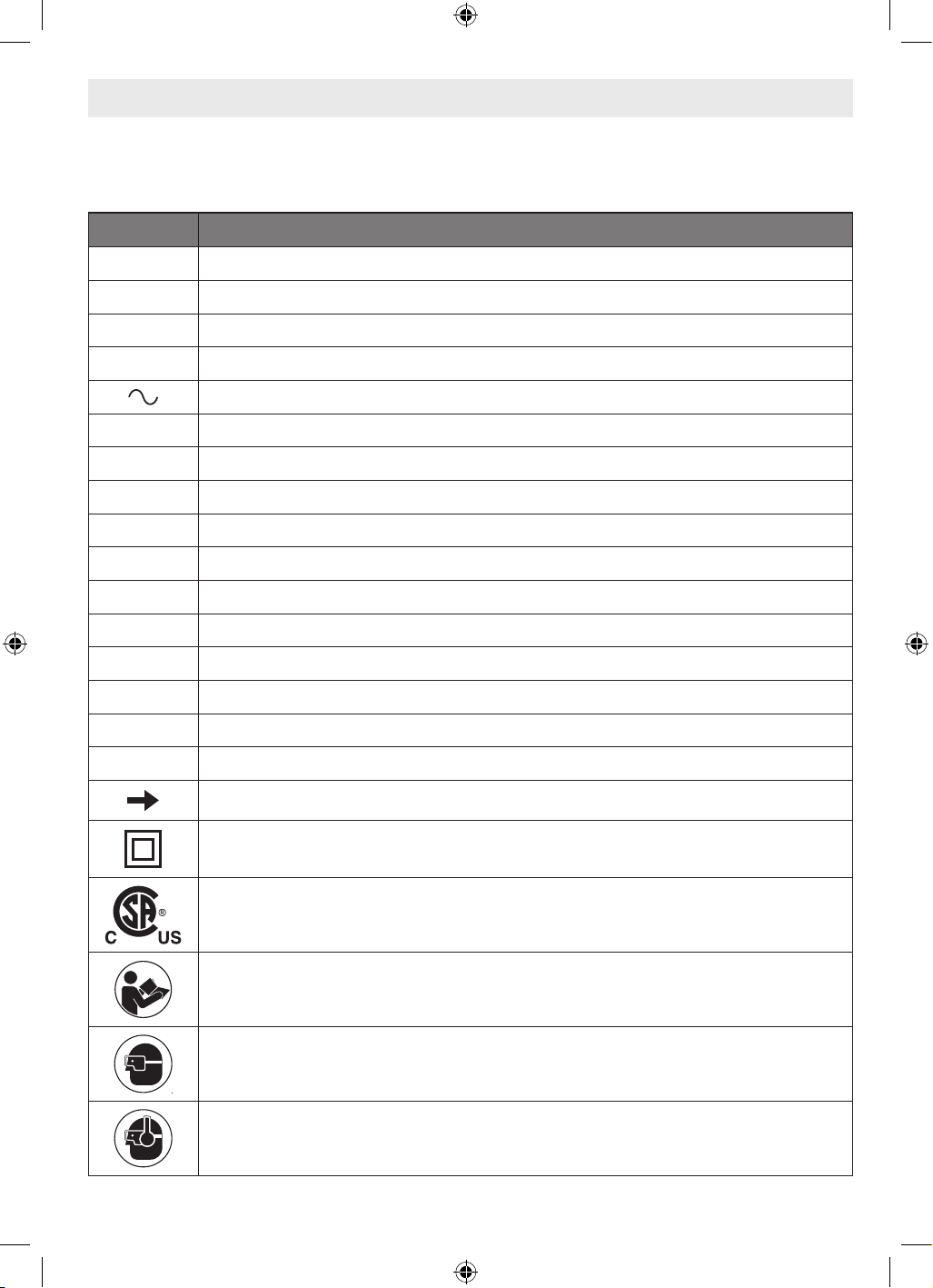
Symbols
Important: Some of the following symbols may be used on your tool. Please study them and
learn their meaning. Proper interpretation of these symbols will allow you to operate the tool
better and safer.
Symbol Designation/Explanation
V Volts (voltage)
A Amperes (current)
Hz Hertz (frequency)
W Watt (power)
Alternating current (type or a characteristic of current)
lb Pounds (weight)
kg Kilograms (weight)
ft Feet (length)
in Inches (length)
m Meter (length)
cm Centimeter (length)
mm Millimeters (length)
F Fahrenheit (temperature)
C Celsius (temperature)
n0 No load speed (rotational speed, at no load)
RPM Revolutions per minute (speed)
Arrow (action in the direction of arrow)
Class II construction (designates double insulated construction tools)
This symbol designates that this tool is listed by the Canadian Standards Asso-
ciation, to United States and Canadian Standards.
Alerts user to read manual.
Alerts user to wear eye protection.
Alerts user to wear hearing protection.
16099221WG GLF55-25 OSI Final 20250228.indd 716099221WG GLF55-25 OSI Final 20250228.indd 7 2/28/2025 8:49:25 AM2/28/2025 8:49:25 AM
8
Symbols
Important: Some of the following symbols may be used on your tool. Please study them and
learn their meaning. Proper interpretation of these symbols will allow you to operate the tool
better and safer.
Symbol Designation/Explanation
Alerts user to wear respiratory protection.
Alerts user to use eye, hearing, and respiratory protection.
Specifications
Model number GLF55-25
Rated current 4.3 A
No load speed 33,000 RPM
Max bit size 1-1/8 in
Collet size 1/4 in
16099221WG GLF55-25 OSI Final 20250228.indd 816099221WG GLF55-25 OSI Final 20250228.indd 8 2/28/2025 8:49:25 AM2/28/2025 8:49:25 AM
9
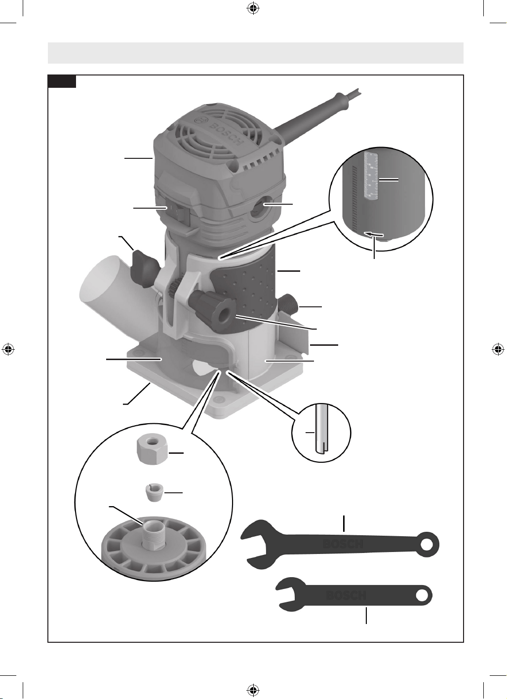
Getting to Know Your GLF55-25 Trim Router
2
1
6
11
15
14
19
16
8
8
13
3
7
18
17
4
5
12
9
10
Fig. 1
16099221WG GLF55-25 OSI Final 20250228.indd 916099221WG GLF55-25 OSI Final 20250228.indd 9 2/28/2025 8:49:25 AM2/28/2025 8:49:25 AM
10
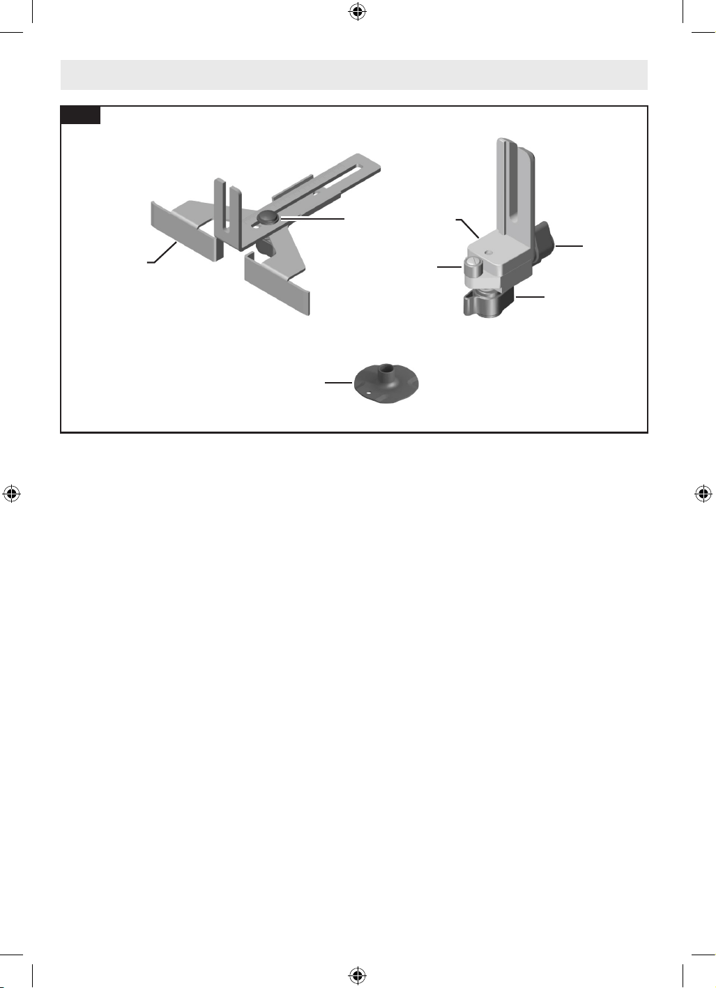
Getting to Know Your GLF55-25 Trim Router
1 On/Off Switch
2 Trim Router
3 Handle (insulated gripping surface)
4 Rear Accessory Thumb Screw
5 Chip Guard
6 Clamping Knob
7 Depth Adjustment Knob
8 Depth Scale
9 Router Bit*
10 Direction of Rotation
11 Subbase
12 Fixed Base
13 Carbon Brush Bracket
14 Collet
15 Collet Nut
16 Spindle
17 Spindle Lock Wrench (10 mm)
18 Collet Nut Wrench (17 mm)
19 Dust Extraction Hood (GLF001)
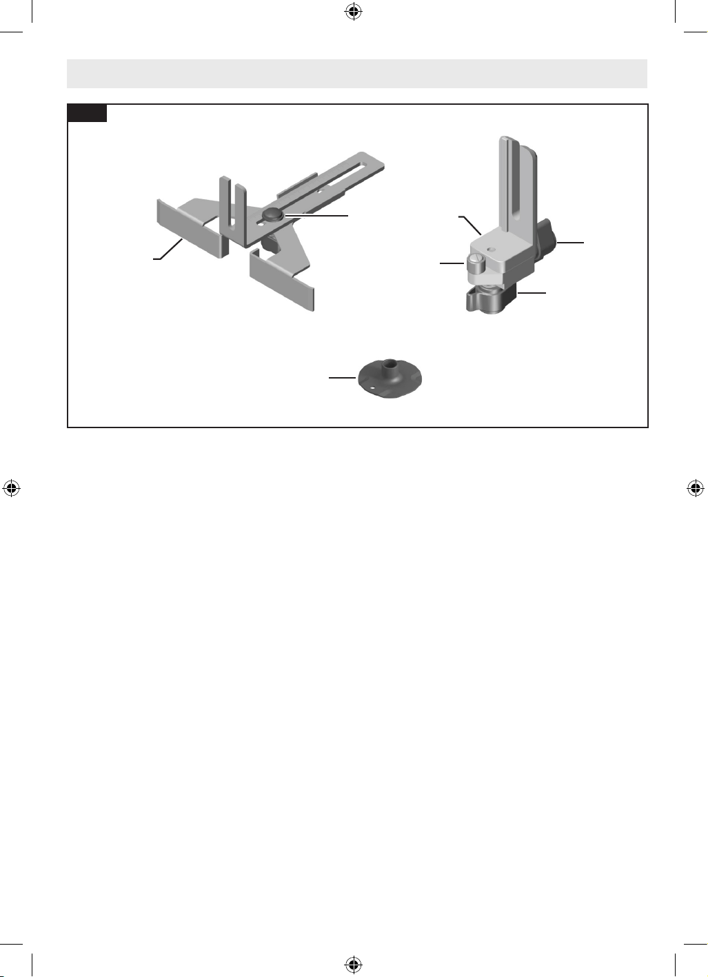
20 Template Guide
21 Straight Edge Guide
22 Wing Bolt for Straight Edge Guide
23 Fixed Base Roller/Bushing Guide (PR003)
24 Wing Nut for Horizontal Alignment of the
Roller/Bushing Guide (Bottom)
25 Wing Nut for Horizontal Alignment of the
Roller/Bushing Guide (Rear)
26 Roller/Bushing
* Sold separately.
20
22
24
21
23
25
26
Fig. 2
16099221WG GLF55-25 OSI Final 20250228.indd 1016099221WG GLF55-25 OSI Final 20250228.indd 10 2/28/2025 8:49:26 AM2/28/2025 8:49:26 AM
11
straight, undamaged, and an appropriate size in
relation to the Collet 14.
1. Follow the steps in “Installing and Remov-
ing the Trim Router in the Fixed Base” on
page 12 to remove the Trim Router 2
from the Fixed Base 12.
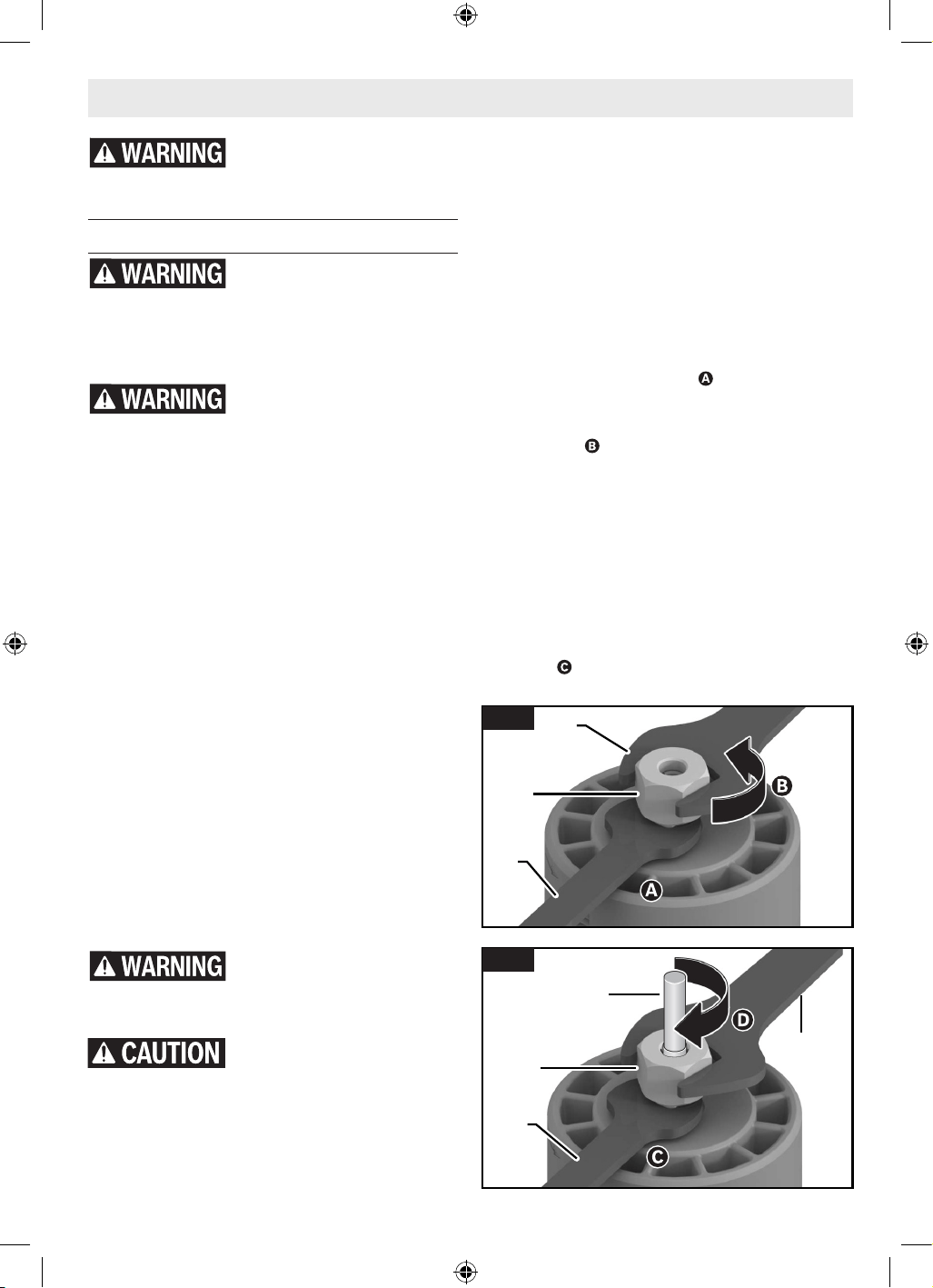
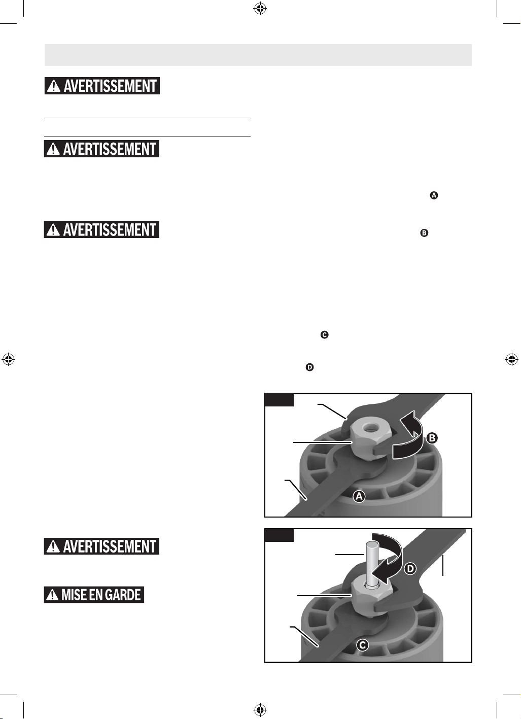
2. Using the Spindle Lock Wrench 17, hold
the Spindle 16 in place .
3. Use the Collet Nut Wrench 18 to loosen
the Collet Nut 15 in a counter-clockwise
direction .
4. If necessary, remove the installed Router
Bit 9.
5. Insert the shank of the Router Bit 9 into
the Collet 14 as far as it will go, then back
the shank out until the cutters are approxi-
mately 1/8” to 1/4” away from the Collet
Nut 15 face.
6. With the Router Bit 9 inserted and Spindle
Lock Wrench 17 holding the Spindle 16 in
place , use the Collet Nut Wrench 18 to
Router Bits
Use only router bits that
have shank diameters that
match the installed collet. Using a router bit
that has a smaller shank could cause the bit to
come loose during operation and become a pro-
jectile.
Never operate router bits at
speeds that are higher than
their maximum rated speed. Router bits run-
ning faster than their rated speed can break
and y apart.
Selecting Router Bits
This tool is designed for a wide variety of rout-
ing applications that use 1/4” shank bits. These
include woodworking applications such as edge
forming and trimming. This router is also ideal
for trimming laminates, phenolics, and other
materials that have been bonded to a substrate
typically with an overhang of the substrate by
about 1/8" (3 mm). A wide assortment of router
bits with different proles are available as ac-
cessories. Only use good quality bits.
Note: Though the router bit may be installed
and removed from the trim router while it is
installed in a base, it is recommended that the
trim router is removed from the base before in-
stalling a bit. See the corresponding section for
the selected base in use on how to separate the
trim router from the base.
Installing/Removing a Router Bit
(Fig. 3, Fig. 4)
Do not use Cutter diameter
larger than 1-1/8". Using
cutter larger than 1-1/8" may result in personal
injury.
Do not tighten collet with-
out a bit. Tightening collet
without a bit inserted may cause damage to the
tool.
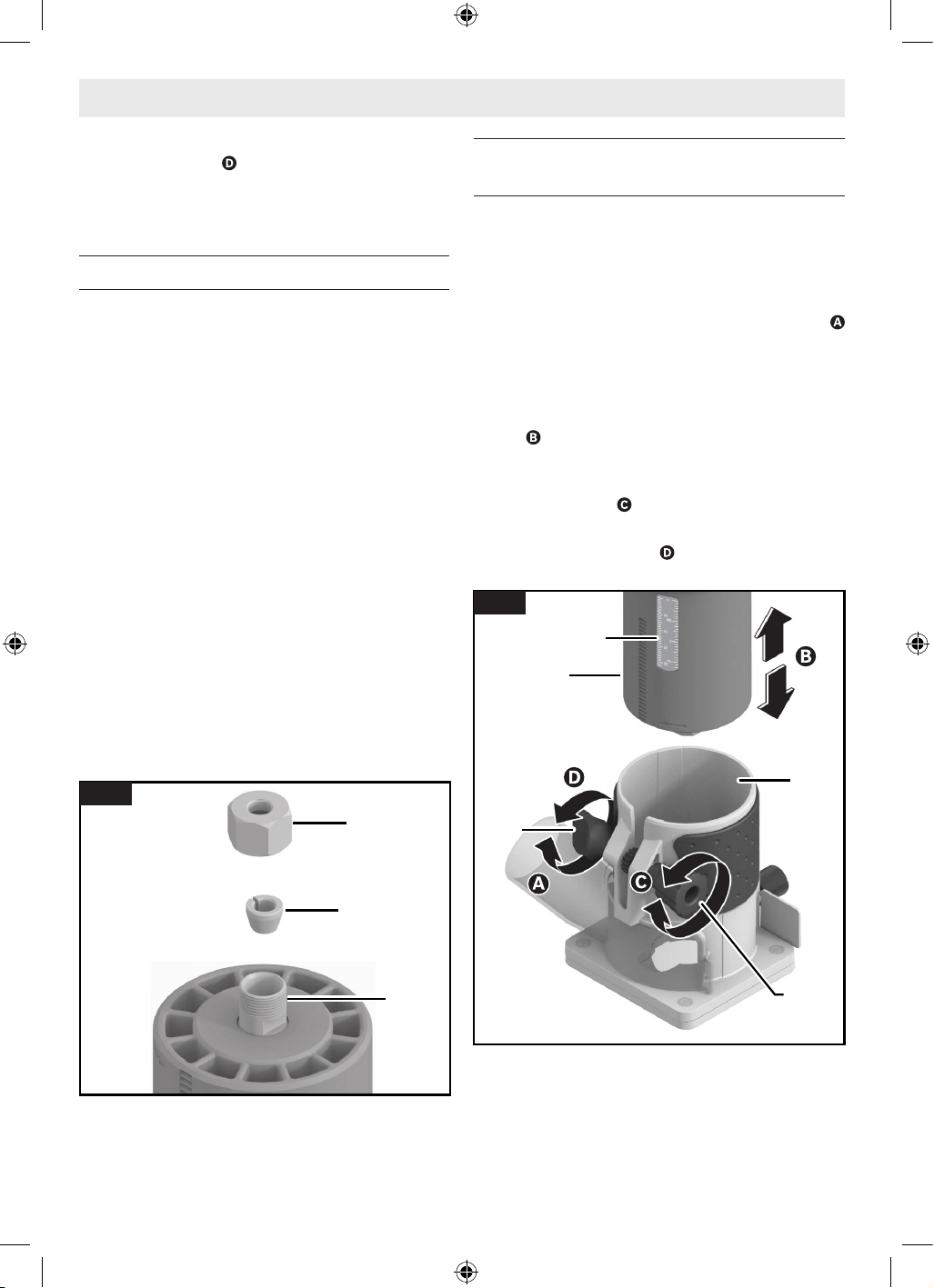
Before attaching selected Router Bit 9, ensure
that the Spindle 16, Collet 14, Collet Nut 15,
and bit shank are clean. The bit shank must be
Assembly and Adjustments
Disconnect the plug from the power source before making any adjustments,
changing accessories, or storing power tools. Such preventive safety measures
reduce the risk of starting the power tool accidentally.
15
18
17
Fig. 3
18
15
9
17
Fig. 4
16099221WG GLF55-25 OSI Final 20250228.indd 1116099221WG GLF55-25 OSI Final 20250228.indd 11 2/28/2025 8:49:26 AM2/28/2025 8:49:26 AM
12
Assembly and Adjustments
rmly tighten the Collet Nut 15 in a clock-
wise direction .
Note: To ensure proper gripping of the Router
Bit 9 and minimize run-out, the shank of the
Router Bit 9 must be inserted at least 5/8”.
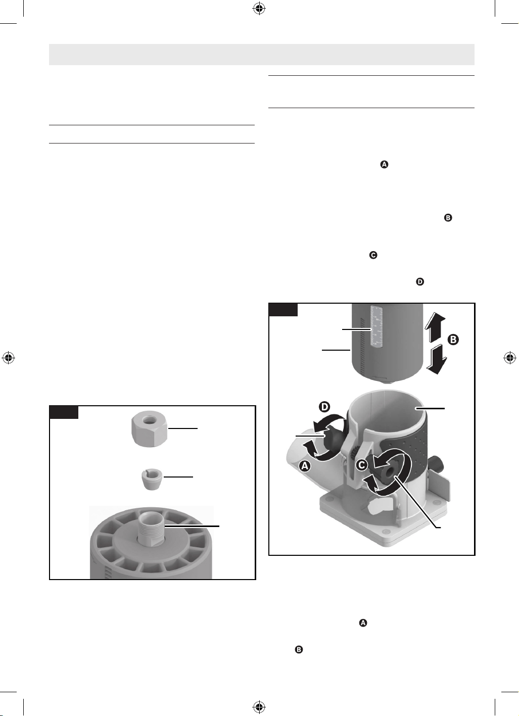
Replacing the Collet
(Fig. 3, Fig. 4, Fig. 5)
This tool includes a pre-installed 1/4” Collet
14, within the Collet Nut 15, that must be used
with a 1/4” diameter accessory shank.
To replace the Collet 14 assembly:
1. Remove the Trim Router 2 from the Fixed
Base 12 as described in “Installing and Re-
moving the Trim Router in the Fixed Base”
below.
2. Using the Spindle Lock Wrench 17, hold
the Spindle 16 in place.
3. Use the Collet Nut Wrench 18 to loosen
the Collet Nut 15 in a counter-clockwise
direction.
4. Unscrew and remove the Collet Nut 15
assembly.
5. Ensure that the Spindle 16 threads are
clean and the Collet 14 is properly tted in
the Collet Nut 15.
6. By hand, screw the new Collet 14 assembly
onto the Spindle 16.
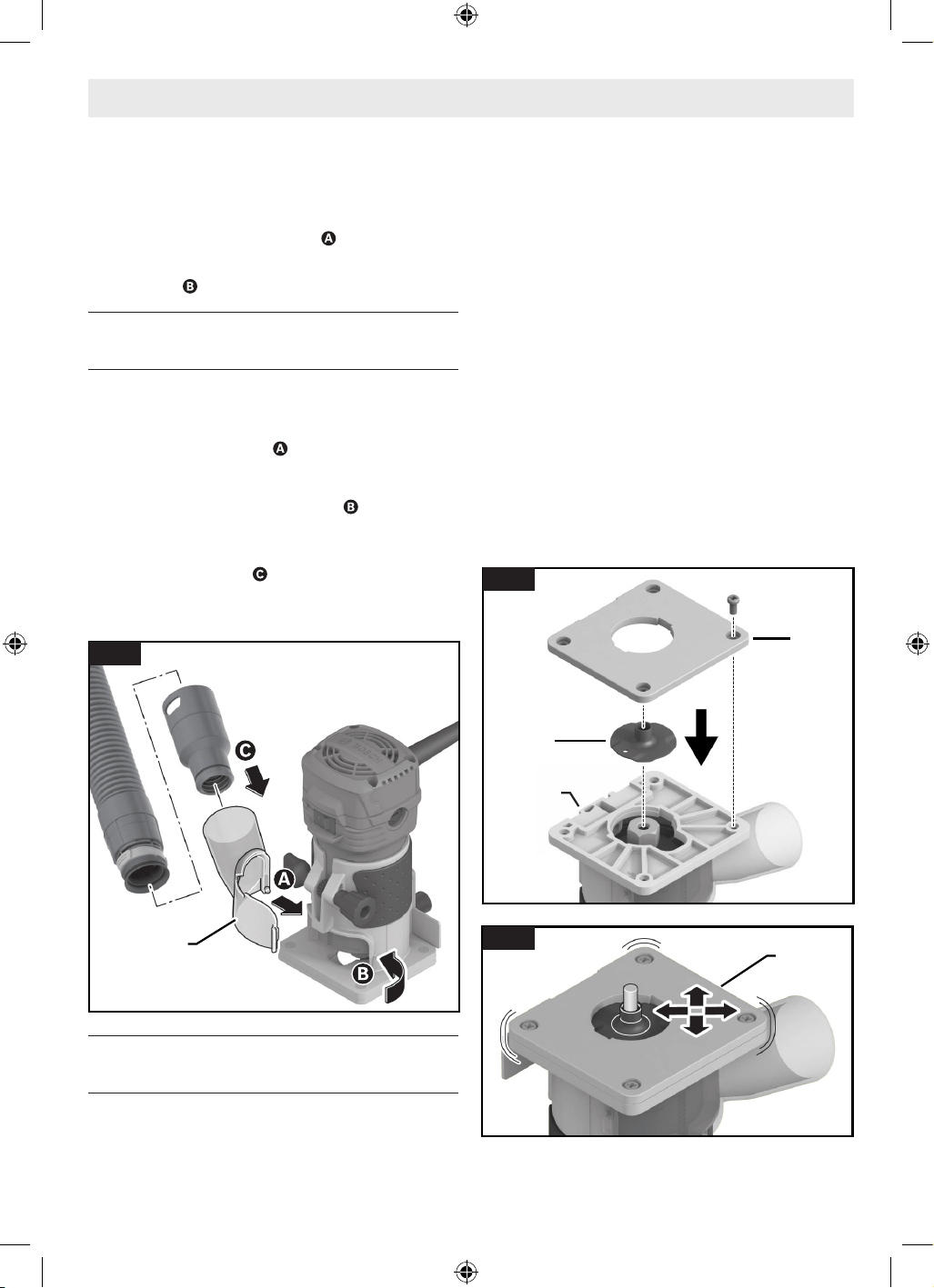
Installing and Removing the Trim
Router in the Fixed Base
(Fig. 6)
Installing the Trim Router to the
Fixed Base
Loosen the clamping mechanism on the Fixed
Base 12 by turning the Clamping Knob 6
counter-clockwise.
1. Align both the Trim Router 2 and the Fixed
Base 12 so they are facing forward.
2. Slide the Trim Router 2 into the Fixed Base
12 .
3. Turn the Depth Adjustment Knob 7 to
precisely reach the desired depth on the
Depth Scale 8 .
4. Firmly tighten the Clamping Knob 6 by
turning it clockwise to secure the Trim
Router 2 in place.
6
7
12
2
8
Fig. 6
15
16
14
Fig. 5
16099221WG GLF55-25 OSI Final 20250228.indd 1216099221WG GLF55-25 OSI Final 20250228.indd 12 2/28/2025 8:49:27 AM2/28/2025 8:49:27 AM
13
Assembly and Adjustments
Removing the Trim Router from the
Fixed Base
1. Loosen the clamping mechanism on the
Fixed Base 12 by turning the Clamping
Knob 6 counter-clockwise .
2. Slide the Trim Router 2 out of the Fixed
Base 12 .
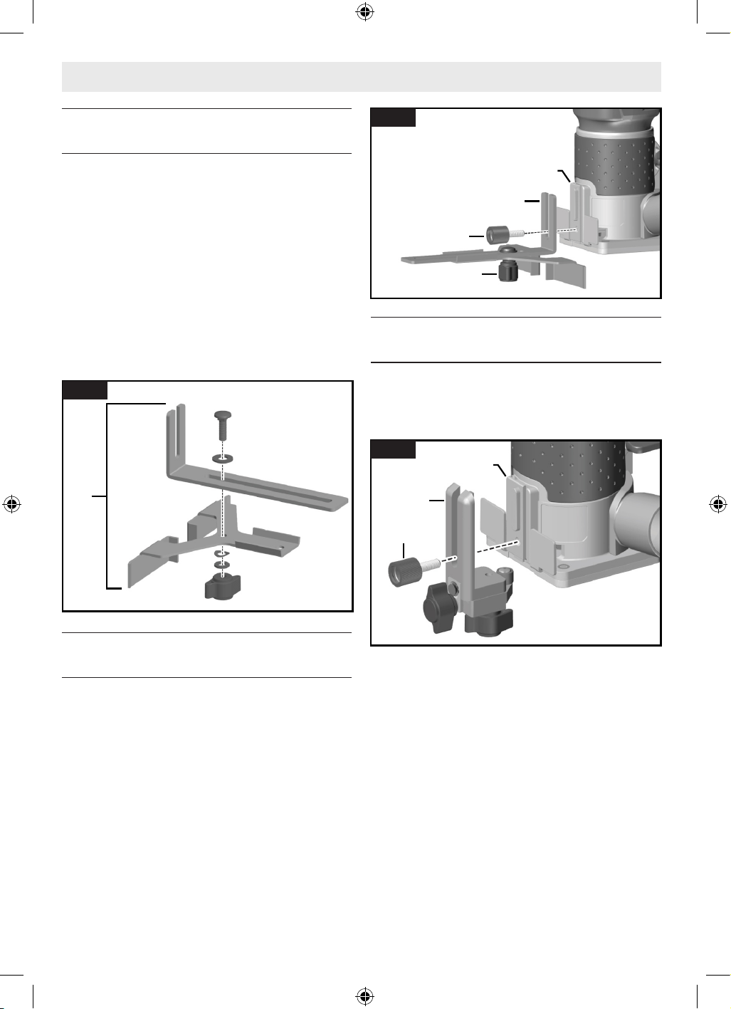
Installing Dust Extraction Hood
(GLF001) (optional accessory)
(Fig. 7)
1. Place the small tab found on the bottom
left of the Dust Extraction Hood 19 into
the slot in the base , then rotate the Dust
Extraction Hood 19 towards the base until
the tab on the right side snaps into the slot
on the right side of the base ; there will
be an audible click.
2. Connect the hood to the vacuum using a
friction t nozzle .
To remove the Dust Extraction Hood 19, grasp
the side of the adapter and pull it forward.
Installing the Template Guide
(optional accessory)
(Fig. 8, Fig. 9)
1. Unscrew the four screws on the underside
of the Subbase 11 and remove the Sub-
base 11.
2. Align the slot conguration and insert the
Template Guide 20 into the Fixed Base 12.
3. Loosely screw the Subbase 11 back onto
the Fixed Base 12. Ensure the Subbase 11
can still move freely.
4. Align the Subbase 11 such that the Tem-
plate Guide 20 is centered on the opening
in the Subbase 11.
Note: The optional RA1151 Centering
Device can be used to precisely center the
template guide or subbase.
5. Hold the Subbase 11 in this position and
rmly tighten the fastening screws.
6. Install the desired Router Bit 9. See “In-
stalling/Removing a Router Bit” on page
11.
Note: The Trim Router 2 must remain installed
to the Fixed Base 12 when installing a Router
Bit 9 while using a Template Guide 20.
19
CLICK!
CLICK!
Fig. 7
11
20
12
Fig. 8
11
Fig. 9
16099221WG GLF55-25 OSI Final 20250228.indd 1316099221WG GLF55-25 OSI Final 20250228.indd 13 2/28/2025 8:49:27 AM2/28/2025 8:49:27 AM
14
Assembly and Adjustments
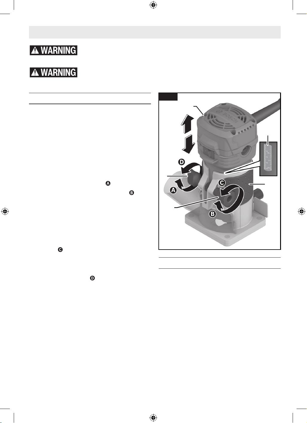
Assembling the Straight Edge Guide
(optional accessory)
(Fig. 10)
The Straight Edge Guide 21 is an optional ac-
cessory that will guide the router parallel to a
straight edge.
The Straight Edge Guide 21 is supplied in two
parts to be fastened together with a bolt, wing
nut, and washers.
To assemble the Straight Edge Guide 21:
1. Position the guide plate on the straight
guide.
2. Secure the two parts together with the
bolt, wing nut, and washers.
Attaching the Straight Edge Guide
(optional accessory)
(Fig. 11)
1. Attach the Straight Edge Guide 21 to the
Fixed Base 12 using the Rear Accessory
Thumb Screw 4.
2. Use the Wing Bolt for Straight Edge Guide
22 to set the required stop depth.
Attaching the Roller/Bushing Guide
(PR003) (optional accessory)
(Fig. 12)
1. Attach the Roller/Bushing Guide 23 to the
Fixed Base 12 using the Rear Accessory
Thumb Screw 4.
21
Fig. 10
12
22
4
21
Fig. 11
12
4
23
Fig. 12
16099221WG GLF55-25 OSI Final 20250228.indd 1416099221WG GLF55-25 OSI Final 20250228.indd 14 2/28/2025 8:49:27 AM2/28/2025 8:49:27 AM
15
Setting Depth of Cut
(Fig. 13)
1. Install the desired Router Bit 9. See “In-
stalling/Removing a Router Bit” on page
11.
2. Install the Trim Router 2 in the Fixed Base
12.
3. Place the router/base assembly on the
workpiece.
4. Loosen the clamping mechanism on the
Fixed Base 12 by turning the Clamping
Knob 6 counter-clockwise .
5. Turn the Depth Adjustment Knob 7 to
slowly lower the router until the router bit
touches the workpiece.
6. Note the reading on the Depth Scale 8 and
add the desired depth-of cut to this value
to determine the target scale value.
7. Lift the router/base assembly from the
workpiece and turn the Depth Adjustment
Knob 7 to lower or raise the Trim Router
2 into the base until the target scale value
is reached.
8. Firmly tighten the Clamping Knob 6 by
turning it clockwise to secure the Trim
Router 2 in place.
9. Ensure that the Trim Router 2 is secured
tightly in the base.
10. Make a trial cut to verify that the Trim
Router 2 is set to the desired depth.
Deep Cuts
For deep cuts, make several progressively deep-
er cuts by starting at one depth and then make
several subsequent passes, increasing the cut-
ting depth with each pass. To be certain that
your depth settings are as desired, you may
want to make test cuts in scrap material before
beginning work.
Operating the Trim Router
(Fig. 14)
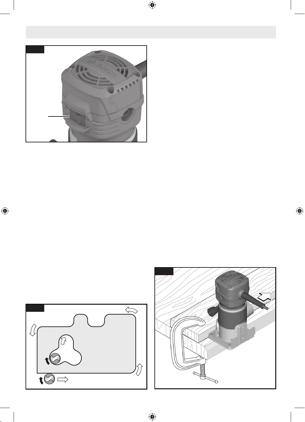
On/Off Switch
Your tool can be turned “ON” or “OFF” by the
On/Off Switch 1 located on the motor housing.
One side of the switch is marked “I” for “ON“,
and the other side of switch is marked “O” for
“OFF“.
TO TURN THE TOOL “ON”: push the side of the
Switch 1 marked “I”.
TO TURN THE TOOL “OFF”: push the side of
the Switch 1 marked “O”.
Disconnect the plug from the power source before making any adjustments,
changing accessories, or storing power tools. Such preventive safety mea-
sures reduce the risk of starting the power tool accidentally.
Use personal protective equipment. Always wear eye protection. Protective
equipment such as a dust mask, non-skid safety shoes, hard hat, or hearing
protection used for appropriate conditions will reduce personal injuries.
Operation
6
7
12
2
8
Fig. 13
16099221WG GLF55-25 OSI Final 20250228.indd 1516099221WG GLF55-25 OSI Final 20250228.indd 15 2/28/2025 8:49:27 AM2/28/2025 8:49:27 AM
16
Therefore, the most efcient cut is made by
feeding the trim router so that the bit turns into
the workpiece, not away. The following gure
shows proper feed for various cuts. How fast
you feed depends on the hardness of the mate-
rial and the size of the cut. For some materi-
als, it is best to make several cuts of increasing
depth.
If the trim router is hard to control, heats up,
runs very slowly or leaves an imperfect cut, con-
sider these causes:
• Wrong direction of feed — hard to control.
• Feeding too fast — overloads motor.
• Dull bit — overloads motor.
• Cut is too large for one pass — overloads
motor.
• Feeding too slow — leaves friction burns on
workpiece.
Feed smoothly and steadily (do not force).
Practice and experience will help with famil-
iarizing how the trim router sounds and feels
when it is working best.
Guiding the Trim Router
(Fig. 16)
The trimmer can be guided through the work-
piece in any of several ways. The method you
use depends, of course, on the demands of the
particular job and on convenience. For routing
Restart Protection
To turn on the router, it must be switched from
OFF to ON while plugged into the power source.
Restart protection helps prevent accidental
startups after power has been interrupted, e.g.
the tool was unplugged with the switch locked
in the ON position. To resume operation, turn
the On/Off Switch 1 to the OFF position, then
restart the tool.
Feeding the Trim Router
(Fig. 15)
This section explains concepts of how to prop-
erly feed the trim router while in operation.
Make sure to read the corresponding sections
for detailed operational steps for each base
type.
As seen from the top of the trim router, the
bit turns clockwise and the bit’s cutting edges
are positioned to best cut into the workpiece.
Operation
1
Fig. 14
Workpiece
Direction of router feed
Fig. 15
Fig. 16
16099221WG GLF55-25 OSI Final 20250228.indd 1616099221WG GLF55-25 OSI Final 20250228.indd 16 2/28/2025 8:49:28 AM2/28/2025 8:49:28 AM
17
Operation
operations such as grooves or dados, it is often
necessary to guide the tool in a line parallel
to a straight edge. One method of obtaining a
straight cut is to securely clamp a board or oth-
er straightedge to the work surface, and guide
the edge of the router sub-base along this path.
Always hold the trim router off the workpiece
when turning the switch ON or OFF. Contact
the workpiece with the router after the trim
router has reached full speed, and remove it
from the workpiece before turning the switch
OFF. Operating in this manner will prolong
switch and motor life and will greatly increase
the quality of your work.
Rate of Feed
When routing or doing related work in wood
and plastics, the best nishes will result if the
depth of cut and feed rate are regulated to keep
the motor operating at high speed. Feed the
trim router at a moderate rate. Soft materials
require a faster feed rate than hard materials.
The router may stall if improperly used or over-
loaded. Reduce the feed rate to prevent possi-
ble damage to the tool. Always be sure the col-
let nut is tightened securely before use. Always
use router bits with the shortest cutting length
necessary to produce the desired cut. This will
minimize router bit run-out and chatter. It may
be necessary to make the cut in more than one
pass with progressively deeper settings to avoid
overloading the motor. If the bit cuts freely and
the motor does not slow down, the cutting
depth is generally correct.
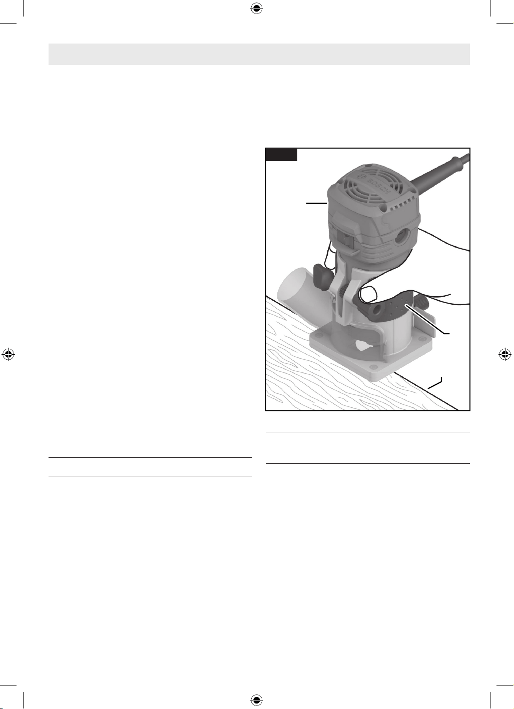
Using the Fixed Base
(Fig. 17)
1. Install the Router Bit 9. See “Installing/Re-
moving a Router Bit” on page 11.
2. Adjust the cutting depth. See “Setting
Depth of Cut” on page 15.
3. Plug the Trim Router 2 into the power
source.
4. Grip the Trim Router 2 rmly by the Insu-
lated Gripping Surface 3.
5. Switch the Trim Router 2 on. See “On/Off
Switch” on page 15.
6. Feed the Trim Router 2 into the workpiece.
See “Feeding the Trim Router” on page
16.
7. Once routing is complete, turn the Trim
Router 2 off. See “On/Off Switch” on page
15.
Using the Straight Edge Guide
(optional accessory)
(Fig. 18)
The Straight Edge Guide 21 can be used to
guide the trim router parallel to a straight edge.
The guide features a scale for accurately posi-
tioning the edge guide relative to the bit. With
the guide installed and adjusted, the router
should be fed normally, keeping the guide in
contact with the edge of the workpiece at all
times.
The router guide can also be positioned directly
under the router base for operations where a
cut is needed close to or at the edge of the
work, such as when rounding off deck planks.
For complete instructions on installation and
operation, please refer to the instructions in-
cluded with this accessory.
2
3
Workpiece
Workpiece
Edge of
Edge of
workpiece
workpiece
Fig. 17
16099221WG GLF55-25 OSI Final 20250228.indd 1716099221WG GLF55-25 OSI Final 20250228.indd 17 2/28/2025 8:49:28 AM2/28/2025 8:49:28 AM
18
Operation
To use the Straight Edge Guide 21:
1. Follow the steps in “Assembling the
Straight Edge Guide (optional accessory)”
and “Attaching the Straight Edge Guide
(optional accessory)” on page 14 to as-
semble and attach the Straight Edge Guide
21.
2. With the guide installed and adjusted, the
trimmer should be fed normally, keeping
the guide in contact with the edge of the
workpiece at all times.
Using the Template Guide (optional
accessory)
(Fig. 19)
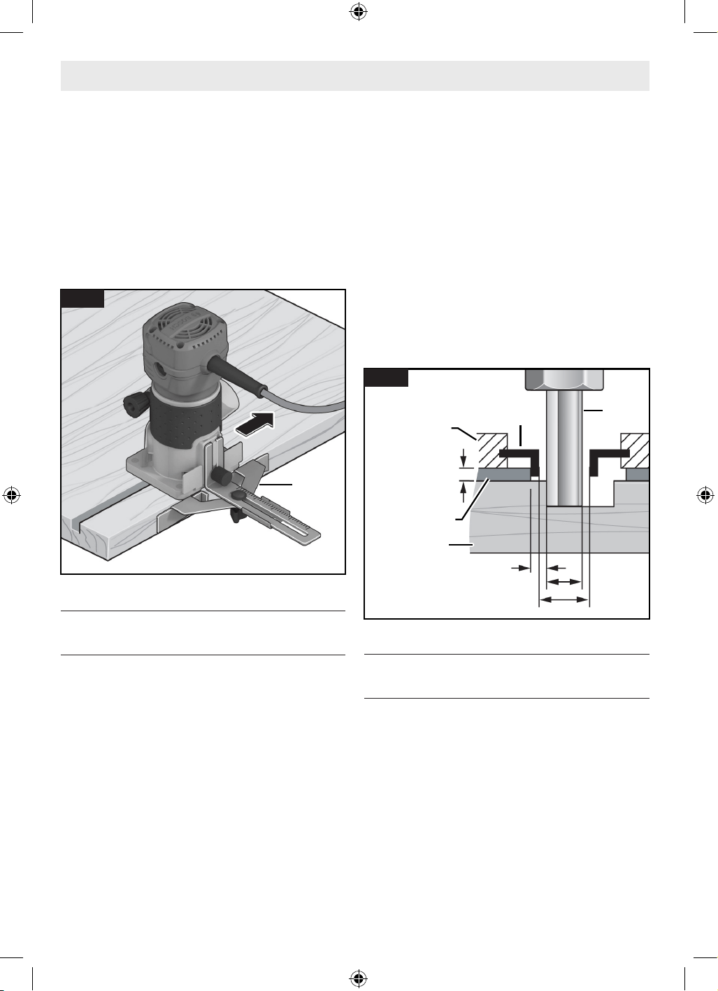
When using a Template Guide 20, use only a
Router Bit 9 with cutters (a) that are at least
1/16” less than the internal diameter of the
template guide (b).
Using the Template Guide 20, you can trans-
fer contours from templates or patterns to the
workpiece. The template will have to be made
to compensate for the distance between the
Router Bit 9 and the outer diameter (OD) of the
Template Guide 20 (the “offset”), as the nal
workpiece will differ in size from the template
pattern by that amount, due to the bit position.
Select the Template Guide 20 that is suitable
for the thickness of the template or pattern.
Due to the protruding height of the Template
Guide 20, the template must have a minimum
thickness of 0.315 in (8 mm).
To use the Template Guide 20:
1. Attach the Template Guide 20 to the router
as described in “Installing the Template
Guide (optional accessory)” on page 13.
2. Place the power tool with the Template
Guide 20 onto the template.
3. Guide the power tool with the protruding
Template Guide 20 along the template us-
ing lateral pressure.
Note: Measure and verify the actual internal di-
ameter (b), offset, and protruding height of the
Template Guide 20 before use.
Using Self-Piloted Bits (sold
separately)
(Fig. 20)
Self-piloted bits have an integral round tip or
ball bearing which rides against the work sur-
face above or below the cutter to control hori-
zontal cutting depth. When using these bits,
neither the roller guide or the straight edge
guide is required. When guiding against a lami-
nated surface, use wax or other lubricant and
do not apply excess pressure or the piloted end
may mar the work. Bearing pilots must be kept
clean and free of adhesive or other residue.
Router bit bearings are sealed and permanently
lubricated, and should be replaced when they
21
Fig. 18
9
5/16"
(8 mm)
a
b
a < b
Offset
20
Template
11
Workpiece
Fig. 19
16099221WG GLF55-25 OSI Final 20250228.indd 1816099221WG GLF55-25 OSI Final 20250228.indd 18 2/28/2025 8:49:28 AM2/28/2025 8:49:28 AM
19
Operation
no longer turn freely to avoid damaging the
work surface.
Using the Roller/Bushing Guide
(PR003) (optional accessory)
(Fig. 21)
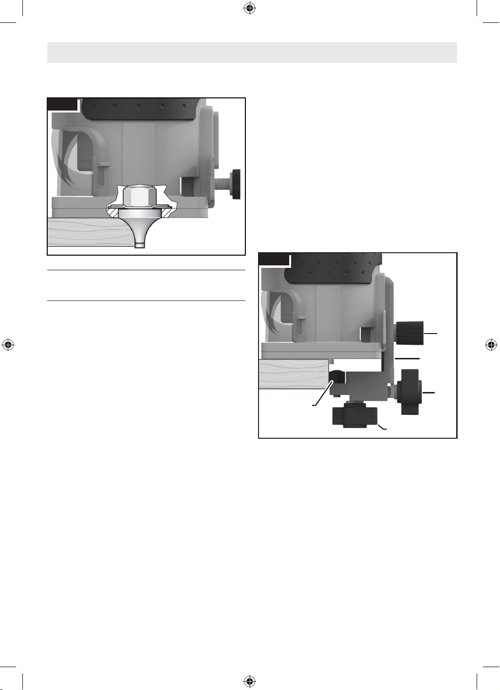
The optional Fixed Base Roller/Bushing Guide
23 is used when edge-forming or trimming with
unpiloted/non-bearing bits.
Follow the steps in “Attaching the Roller/Bush-
ing Guide (PR003) (optional accessory)” on
page 14 to install the guide.
Vertical Adjustment of the Roller/
Bushing Guide
(Fig. 21)
1. Loosen the Rear Accessory Thumb Screw
4 and adjust up or down as necessary to
allow the Fixed Base Roller/Bushing Guide
23 to ride on the intended guiding surface.
2. Tighten the Rear Accessory Thumb Screw
4.
Horizontal Adjustment of the Roller/
Bushing Guide
(Fig. 21)
Whether making straight or bevel cuts, the
width of material removed is determined by the
distance between the front of the router bit’s
cutter and the front of the roller/bushing.
Adjust the front of the roller/bushing as fol-
lows:
1. Loosen the Wing Nut for Horizontal Align-
ment (Bottom) 24.
2. Rotate the Wing Nut for Horizontal Align-
ment (Rear) 25 to move the Roller/Bushing
26 in or out to create the amount of cutter
exposure needed to trim the laminate ush
with the guiding surface or to create the
desired bevel.
3. Be sure the bit clears the top of the Roller/
Bushing Guide 23 by at least 1/8" (3 mm)
to avoid damage.
4. Tighten the Wing Nut for Horizontal Align-
ment (Bottom) 24.
5. Make a trial cut to check the setting and
re-adjust as necessary.
Use of the Roller/Bushing Guide
With the guide installed and adjusted, the rout-
er should be fed normally, keeping the guide
in contact with the edge of the workpiece at
all times.
To maintain a consistent width of cut, a con-
sistent angle must be maintained between the
router and the workpiece.
Fig. 20
4
23
24
25
26
Fig. 21
16099221WG GLF55-25 OSI Final 20250228.indd 1916099221WG GLF55-25 OSI Final 20250228.indd 19 2/28/2025 8:49:28 AM2/28/2025 8:49:28 AM
20
Cleaning
Certain cleaning agents and solvents damage
plastic parts. Some of these are: gasoline,
carbon tetrachloride, chlorinated cleaning sol-
vents, ammonia and household detergents that
contain ammonia.
Periodically remove dust from the tool by wip-
ing with a clean rag or using compressed air on
the inside of the base and motor unit as well as
the ne depth adjustment system.
Remove dust and debris from all vents. Keep
the trim router clean, dry and free of oil or
grease. Use only mild soap and a damp cloth
to clean the trim router, since certain clean-
ing agents and solvents are harmful to plas-
tics and other insulated parts. Some of these
include gasoline, turpentine, lacquer thinner,
paint thinner, chlorinated cleaning solvents,
ammonia and household detergents containing
ammonia. Never use ammable or combustible
solvents around tools.
Storage and Maintenance
Store trim router and accessories in a cool dry
place and avoid freezing. Before use, check
router bits for cracks and fractures, do not use
if damage is suspected.
Maintenance
General Maintenance
Keep your trim router and accessories in good
working order by adopting a regular mainte-
nance program. Inspect your trim router for is-
sues such as undue noise, binding of moving
parts, breakage of parts, or any other condition
that may affect trim router operation.
Service
Have your power tool serviced by a qualied
repair person using only identical replacement
parts. This will ensure that the safety of the
power tool is maintained.
Tool Lubrication
Your Bosch tool has been properly lubricated
and is ready to use. It is recommended that
tools with gears be regreased with a special
gear lubricant at every brush change.
Carbon Brushes
The brushes and commutator in your tool have
been engineered for many hours of dependable
service. To maintain peak efciency of the mo-
tor, we recommend every two to six months the
brushes be examined. Only genuine Bosch re-
placement brushes specially designed for your
tool should be used.
Bearings
Bearings which become noisy (due to heavy
load or very abrasive material cutting) should
be replaced at once to avoid overheating or mo-
tor failure.
Disconnect the plug from the power source before making any adjustments,
changing accessories, or storing power tools. Such preventive safety mea-
sures reduce the risk of starting the power tool accidentally.
16099221WG GLF55-25 OSI Final 20250228.indd 2016099221WG GLF55-25 OSI Final 20250228.indd 20 2/28/2025 8:49:28 AM2/28/2025 8:49:28 AM
21
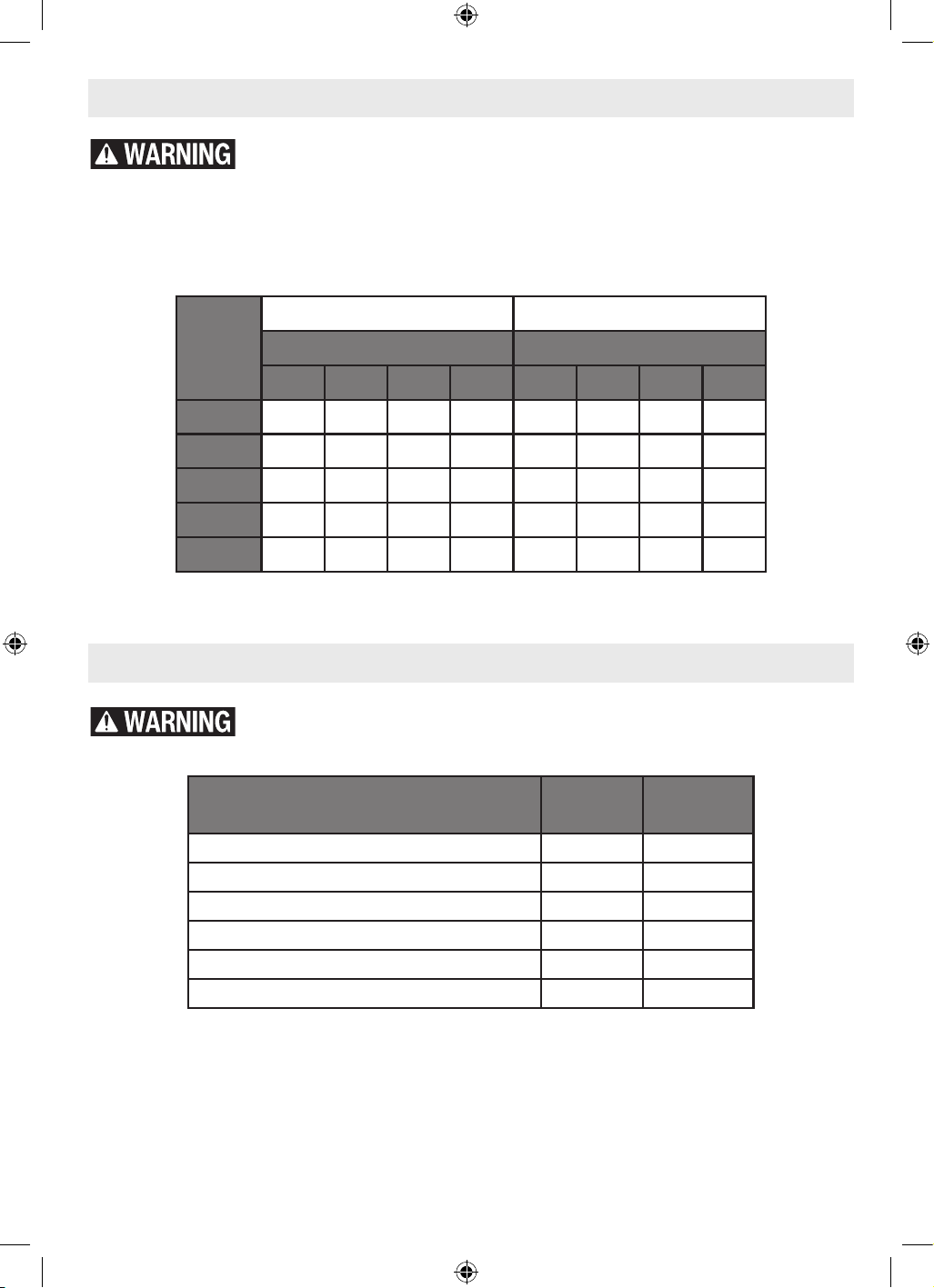
Extension Cords
Accessories
If an extension cord is necessary, a cord with adequate size conductors that
is capable of carrying the current necessary for your tool must be used. This
will prevent excessive voltage drop, loss of power or overheating. Grounded tools must use 3-wire
extension cords that have 3- prong plugs and receptacles.
Note: The smaller the gauge number, the heavier the cord.
Recommended Sizes of Extension Cords for 120 Volt Alternating Current Tools
Tool’s
Ampere
Rating
Cord Size in A.W.G. Wire Sizes in mm2
Cord Length in Feet Cord Length in Meters
25 50 100 150 15 30 60 120
3-6 18 16 16 14 0.75 0.75 1.5 2.5
6-8 18 16 14 12 0.75 1.0 2.5 4.0
8-10 18 16 14 12 0.75 1.0 2.5 4.0
10-12 16 16 14 12 1.0 2.5 4.0 –
12-16 14 12 – – – – – –
Do not use attachments/accessories other than those specied by Bosch.
Use of attachments/accessories not specied for use with the tool described
in this manual may result in damage to tool, property damage, and/or personal injury.
Acessories Included
Sold
Separately
Straight Edge Guide • •
Fixed Base Roller/Brushing Guide (PR003) • •
Template Guide • •
Dust Extraction Hood (GLF001) • •
Self-Piloted Bits •
Router Bits •
16099221WG GLF55-25 OSI Final 20250228.indd 2116099221WG GLF55-25 OSI Final 20250228.indd 21 2/28/2025 8:49:28 AM2/28/2025 8:49:28 AM
22
Troubleshooting
Disconnect the plug from the power source before assembly, adjustments,
troubleshooting or changing accessories. Such preventive safety measures
reduce the risk of starting the tool accidentally, which may result in personal injury.
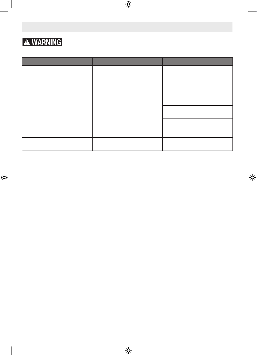
Trouble Cause Corrective Action
Trim Router is hard to control. Incorrect direction of feed.
Reverse the direction of feed.
See “Feeding the Trim Router”
on page 16.
Trim router runs slow; rough
cuts, poor cutting perfor-
mance.
Dull or damaged router bit. Replace router bit.
Trim router is overloaded.
Back off the workpiece to
reduce the load.
Feeding too fast, adjust the
speed of feed.
Cut is too large for one pass.
Make multiple progressively
deeper cuts.
Friction burns on the work-
piece.
Feeding too slow. Adjust the speed of feed.
16099221WG GLF55-25 OSI Final 20250228.indd 2216099221WG GLF55-25 OSI Final 20250228.indd 22 2/28/2025 8:49:28 AM2/28/2025 8:49:28 AM
23
Avertissements généraux relatifs à la sécurité pour
les outils électriques ...........................24
Avertissements de sécurité pour défonceuses . . . . . . . . . .25
Avertissements supplémentaires concernant
la sécurité....................................26
Mise au rebut .................................27
Utilisation prévue .................................27
Symboles........................................28
Spécifications ....................................29
Familiarisez-vous avec votre ébouteuse pour coupe de
finition GLF55-25. ............................30
Assemblage et réglages ............................32
Fraises ......................................32
Remplacement de la douille .....................33
Installation et retrait de l’ébouteuse dans la base
fixe .....................................33
Installation de la hotte d’extraction de la poussière
(GLF001) (accessoire en option).............34
Installation du guide de gabarit (accessoire en
option) ..................................34
Assemblage du guide de chant (accessoire en
option) ..................................35
Attachement du guide de chant (accessoire en
option) ..................................35
Attachement du guide de la douille/du rouleau
(PR003) (accessoire en option)..............35
Fonctionnement de l'outil...........................36
Réglage de la profondeur de coupe ...............36
Utilisation de l’affleureuse portative...............36
Utilisation une base fixe ........................38
Utilisation du guide de chant (accessoire en
option) ..................................38
Utilisation du guide de gabarit (accessoire en
option) ..................................39
Utilisation de fraises autopilotées (vendu
séparément)..............................39
Utilisation du guide de la douille/du rouleau
(PR003) (accessoire en option)..............40
Entretien ........................................41
Maintenance générale..........................41
Service......................................41
Lubrification de l’outil ..........................41
Balais ou charbons ............................41
Paliers et roulements...........................41
Nettoyage....................................41
Rangement et maintenance .....................41
Cordons de rallonge ...............................42
Accessoires......................................42
Recherche de la cause des problèmes.................43
Table des matières
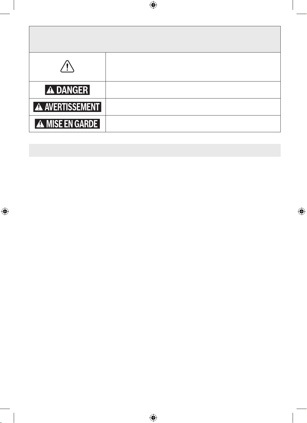
Symboles relatifs à la sécurité
Les définitions ci-dessous décrivent le niveau de gravité pour chaque terme concernant des précautions à prendre.
Veuillez lire le mode d’emploi et lire la signification de ces symboles.
C’est le symbole d’alerte relatif à la sécurité. Il est utilisé pour vous avertir de
l’existence possible d’un risque de blessure. Obéissez à tous les messages relatifs à la
sécurité qui suivent ce symbole pour éviter tout risque de blessure ou même de mort.
DANGER indique une situation dangereuse qui, si elle n’est pas évitée, causera la
mort d’une personne ou une blessure grave.
AVERTISSEMENT indique une situation dangereuse qui, si elle n’est pas évitée,
pourrait causera la mort d’une personne ou une blessure grave.
MISE EN GARDE indique une situation dangereuse qui, si elle n’est pas évitée,
pourrait causer une blessure légère ou modérée.
16099221WG GLF55-25 OSI Final 20250228.indd 2316099221WG GLF55-25 OSI Final 20250228.indd 23 2/28/2025 8:49:29 AM2/28/2025 8:49:29 AM

24
Avertissements généraux relatifs à la sécurité pour les outils électriques
Lisez toutes les consignes de sécurité, instructions, illustrations et spécifications
fournies avec cet outil électrique. Le non-respect de toutes les instructions figurant ci-
après pourrait causer un choc électrique, un incendie et/ou des blessures graves.
CONSERVEZ TOUS LES AVERTISSEMENTS ET TOUTES LES INSTRUCTIONS POUR RÉFÉRENCE FUTURE.
Le terme « outil électrique » dans les avertissements fait référence à votre outil électrique à cordon d’alimentation électrique
branché dans une prise secteur ou à votre outil électrique à piles (sans fil).
1. Sécurité de la zone de travail
a. Gardez votre zone de travail propre et bien éclairée.
Des zones encombrées ou sombres sont propices aux
accidents.
b. N’utilisez pas des outils électriques dans une
atmosphère explosive, par exemple en présence de
liquides, de gaz ou de poussières inflammables. Les
outils électriques produisent des étincelles qui risquent
de mettre feu aux poussières ou émanations de fumée.
c. Gardez les enfants et les autres personnes présentes
à une distance suffisante lorsque vous utilisez un
outil élec-trique. Des distractions risqueraient de vous
faire perdre le contrôle.
2. Sécurité électrique
a. La fiche de l’outil électrique doit correspondre
à la prise de courant. Ne modifiez jamais une
fiche de quelque façon que ce soit. N’utilisez pas
d’adaptateurs de fiches avec des outils électriques
mis à la terre/à la masse. L’emploi de fiches non
modifiées et de prises de courant correspondant
naturellement aux fiches réduira le risque de choc
électrique.
b. Évitez tout contact de votre corps avec des surfaces
mises à la terre ou à la masse telles que des
surfaces de tuyaux, de radiateurs, de cuisinières
et de réfrigérateurs. Il existe un risque accru de choc
électrique si votre corps est en contact avec la terre ou
la masse.
c. N’exposez pas d’outils électriques à la pluie ou à un
environnement humide. La pénétration d’eau dans un
outil électrique augmentera le risque de choc électrique.
d. N’utilisez pas le cordon de façon abusive. N’utilisez
pas le cordon pour porter, tirer ou débrancher l’outil
électrique. Tenez le cordon à distance de toute source
de chaleur, d’huile, de bords tranchants ou de pièces
mobiles. Des cordons endommagés ou entortillés
augmentent le risque de choc électrique.
e. Lorsque vous utilisez un outil électrique à l’extérieur,
employez un cordon de rallonge approprié pour un
emploi à l’extérieur. L’utilisation d’un cordon approprié
pour une utilisation à l’extérieur réduit le risque de choc
électrique.
f. Si l’utilisation d’un outil électrique dans un endroit
humide est inévitable, utilisez une alimentation
protégée par un disjoncteur de fuite à la terre.
L’utilisation d’un tel circuit réduit le risque de choc
électrique.
3. Sécurité personnelle
a. Faites preuve de vigilance et de bon sens, et observez
attentivement ce que vous faites lorsque vous
utilisez un outil électrique. N’utilisez pas un outil
électrique si vous êtes fatigué(e) ou sous l’influence
de drogues, d’alcool ou de médicaments. Un simple
moment d’inattention pendant que vous utilisez un outil
électrique pourrait causer une blessure grave.
b. Utilisez des équipements de protection individuelle.
Portez toujours des équipements de protection des
yeux. Des équipements de protection tels qu’un masque
de protection contre la poussière, des chaussures de
sécurité anti-dérapantes, un casque ou un dispositif de
protection de l’ouïe utilisés en fonction des conditions
réduiront le nombre des blessures.
c. Prévenez tout risque de mise en marche accidentelle.
Assurez-vous que l’interrupteur est dans la position
d’arrêt (OFF) avant de connecter l’appareil à une
source d’alimentation et/ou à un bloc-piles, de le
soulever ou de le transporter. Le fait de transporter
des outils électriques avec le doigt sur l’interrupteur
ou de mettre sous tension des outils électriques avec
l’interrupteur en position de marche invite les accidents.
d. Retirez toute clé de réglage pouvant être attachée à
l’outil avant de mettre l’outil électrique sous tension.
Une clé laissée attachée à une pièce en rotation de l’outil
électrique pourrait causer une blessure.
e. Ne vous penchez pas excessivement au-dessus de
l’outil. Veillez à toujours garder un bon équilibre et
un appui stable. Ceci permet de mieux contrôler l’outil
électrique dans des situations inattendues.
f. Portez des vêtements appropriés. Ne portez pas de
bijoux ou de vêtements amples. Gardez vos cheveux
et vos vêtements à une distance suffisante des pièces
CONSERVEZ CES INSTRUCTIONS
16099221WG GLF55-25 OSI Final 20250228.indd 2416099221WG GLF55-25 OSI Final 20250228.indd 24 2/28/2025 8:49:29 AM2/28/2025 8:49:29 AM

25
mobiles. Vêtements amples, bijoux ou cheveux longs
pourraient être attrapés par des pièces mobiles.
g. Si des dispositifs sont fournis pour le raccordement
d’accessoires d’extraction et de collecte de la
poussière, assurez-vous qu’ils sont connectés et
utilisés de façon appropriée. L’emploi correct des
accessoires de collecte de la poussière peut réduire les
dangers associés à la poussière.
h. Ne laissez pas la familiarité résultant de l’utilisation
fréquente des outils vous inciter à devenir
complaisant(e) et à ignorer les principes de sécurité
relatifs aux outils. Une action négligente pourrait
causer des blessures graves en une fraction de seconde.
4. Utilisation et entretien de l’outil électrique
a. N’imposez pas de contraintes excessives à l’outil
électrique. Utilisez l’outil électrique approprié pour
votre application. L’outil électrique correct fera le travail
plus efficacement et avec plus de sécurité à la vitesse à
laquelle il a été conçu pour fonctionner.
b. N’utilisez pas l’outil électrique si l’interrupteur
de marche/arrêt ne permet pas de le mettre sous
tension/hors tension. Tout outil électrique qui ne peut
pas être contrôlé par son interrupteur est dangereux et
doit être réparé.
c. Débranchez la fiche de la source d’alimentation
électrique et/ou retirez le bloc-piles de l’outil
électrique (s’il est amovible) avant d’y apporter de
quelconques modifications, de changer d’accessoire
ou de ranger l’outil électrique. De telles mesures
de sécurité préventives réduisent le risque de
déclenchement accidentel de l’outil électrique.
d. Rangez les outils électriques qui ne sont pas utilisés
activement hors de portée des enfants, et ne laissez
aucune personne n’ayant pas lu ces instructions et ne
sachant pas comment utiliser un tel outil électrique
se servir de cet outil. Les outils électriques sont
dangereux quand ils sont entre les mains d’utilisateurs
n’ayant pas reçu la formation nécessaire à leur utilization.
e. Entretenez de façon appropriée les outils électriques
et les accessoires. Assurez-vous que les pièces en
mouvement sont bien alignées et qu’elles ne se
coincent pas, qu’il n’y a pas de pièces cassées ou
qu’il n’existe aucune situation pouvant affecter
le fonctionnement de l’outil électrique. Si l’outil
électrique est endommagé, faites-le réparer avant de
vous en servir à nouveau. De nombreux accidents sont
causés par des outils électriques mal entretenus.
f. Gardez les outils de coupe tranchants et propres. Des
outils de coupe entretenus de façon adéquate avec des
bords de coupe tranchants sont moins susceptibles de
se coincer et sont plus faciles à controller.
g. Utilisez l’outil électrique, les accessoires, les
embouts de l’outil, etc. conformément à ces
instructions, en tenant compte des conditions de
travail et de la tâche à accomplir. L’utilisation de l’outil
électrique pour des opérations différentes de celles
pour lesquelles il est conçu pourrait causer une situation
dangereuse.
h. Gardez les poignées et les surfaces de préhension
propres, sèches et exemptes de toute trace d’huile ou
de graisse. Les poignées et les surfaces de préhension
glissantes ne permettent pas une manipulation et un
contrôle sûrs de l’outil dans des situations inattendues.
5. Service après-vente
a. Faites entretenir votre outil électrique par un
réparateur compétent n’utilisant que des pièces de
rechange identiques. Ceci assurera le maintien de la
sécurité de l’outil électrique.
Avertissements généraux relatifs à la sécurité pour les outils électriques
CONSERVEZ CES INSTRUCTIONS
Avertissements de sécurité pour défonceuses
Tenir l’outil électrique uniquement par les surfaces de
réhension isolantes, car la fraise peut être en contact avec
son proper câble. Le fait de couper un fil « sous tension » peut
également mettre « sous tension » les parties métalliques
exposées de l’outil électrique et provoquer un choc électrique
sur l’opérateur.
Utilisez des brides de fixation ou un autre moyen pratique
de sécuriser et de supporter l’ouvrage sur une plateforme
stable. Si vous tenez l’ouvrage à la main ou contre votre
corps, ceci le rendra instable et pourrait causer une perte de
contrôle.
16099221WG GLF55-25 OSI Final 20250228.indd 2516099221WG GLF55-25 OSI Final 20250228.indd 25 2/28/2025 8:49:29 AM2/28/2025 8:49:29 AM
26
Avertissements supplémentaires concernant la sécurité
Pour couper dans des murs existants ou autres endroits
aveugles pouvant dissimuler des fils électriques,
débranchez tous les fusibles ou les disjoncteurs
alimentant ce lieu de travail.
Assurez-vous toujours que la surface de travail est
exempte de clous et autres objets étrangers. La coupe
dans un clou peut faire sauter la lame et l'outil, et ainsi abîmer
la lame.
Ne tenez jamais le matériau d'une main et l'outil de l'autre
lorsque vous en faites usage.
Ne placez jamais les mains sous la surface de coupe
ou à proximité de celleci. Il est plus sûr de cramponner le
matériau et de guider l'outil des deux mains.
Ne posez jamais le matériau sur des surfaces dures telles
que le béton, la pierre, etc. La lame de coupe en saillie peut
faire sauter l'outil.
Portez toujours des lunettes de sécurité et un masque
anti-poussières. N'utilisez l'outil qu'à un endroit bien aéré.
L'utilisation de dispositifs de sécurité personnelle et le travail
dans un environnement sûr réduisent les risques de blessures.
Après avoir changé les lames ou effectué quelque réglage
que ce soit, assurez-vous que l'écrou de la douille et tout
autre dispositif de réglage sont bien serrés. Un dispositif
de réglage lâche peut bouger soudainement et causer
ainsi une perte de contrôle avec projection violente des
composants en rotation.
Ne mettez jamais l'outil en marche alors que la lame est
enfoncée dans le matériau. Le tranchant de la lame peut se
coincer dans le matériau et vous faire perdre le contrôle du
couteau.
Tenez toujours le couteau des deux mains durant la mise
en marche. Le couple de réaction du moteur peut faire tordre
l'outil.
Le sens d'introduction de la lame dans le matériau est très
important, et il est lié au sens d'introduction de la lame.
Lorsque vous regardez l'outil depuis le dessus, la lame
tourne en sens horaire. Le sens d'introduction du couteau
doit être antihoraire.
REMARQUE : Les coupes intérieures et extérieures né-
cessiteront des sens de déplacement différents - référez-
vous à la section consacrée au sens de déplacement de
la toupie. Si l'outil est introduit dans le mauvais sens,
le tranchant de la lame peut sortir du matériau et tirer
l'outil dans le sens de cette introduction.
N'utilisez jamais de lames émoussées ou abîmées. Les
lames affilées doivent être maniées soigneusement. Les
mèches abîmées peuvent se rompre brusquement durant
l'usage. Les lames émoussées nécessitent plus de force pour
pousser l'outil, causant éventuellement un bris de la lame.
Ne touchez jamais la lame durant ou immédiatement
après l'usage. Après usage, la lame est trop chaude pour être
touchée à main nue.
Ne posez jamais l'outil avant que le moteur ne se soit
arrêté complètement. La lame en rotation peut saisir la
surface et vous faire perdre le contrôle de l'outil.
N’utilisez pas de fraises de diamètre supérieur à 1-1/2
po. L’utilisation d’une fraise de diamètre supérieur à 1-1/2 po
pourrait entraîner des blessures.
Utilisez uniquement des fers de toupie dont le diamètre
de la tige correspond à celui de la douille installée.
L'utilisation d'un fer de toupie dont la tige est plus petite peut
entraîner le détachement du fer pendant son fonctionnement,
et il risquerait de devenir un projectile.
N'utilisez jamais des fers de toupie à des vitesses
supérieures à leur vitesse nominale maximale. Des fers
de toupie fonctionnant à une vitesse supérieure à leur vitesse
nominale risqueraient de se casser et d’être projetés dans
l’air.
L’emploi d’un GFCI et de dispositifs de protection
personnelle tels que gants et chaussures d’électricien en
caoutchouc améliorent votre sécurité personnelle.
Maintenez les poignées sèches et exemptes d’huile et de
graisse. On ne pas maîtriser un outil électroportatif en toute
sécurité quand on a les mains glissantes.
Créez un agenda d’entretien périodique pour votre outil.
Quand vous nettoyez un outil, faites attention de n’en
démonter aucune pièce car il est toujours possible de mal
remonter ou de pincer les fils internes ou de remonter
incorrectement les ressorts de rappel des capots de
protection. Certains agents de nettoyage tels que l’essence,
le tétrachlorure de carbone, l’ammoniaque, etc. risquent
d’abîmer les plastiques.
Des travaux de pon-
çage, de sciage, de
meulage et de perçage réalisés avec un outil électrique et
d’autres travaux de construction peuvent produire des
poussières contenant des produits chimiques qui sont des
causes reconnues de cancer, de malformation congénitale
ou d’autres problèmes reproductifs. Ces produits
chimiques sont, par exemple :
• le plomb provenant de peinture au plomb,
• des cristaux de silice provenant des briques et du ciment,
ainsi que d’autres produits de maçonnerie, et
• de l’arsenic et du chrome provenant de bois de
construction traité par des produits chimiques.
Le niveau de risque causé par de telles expositions varie
en fonction de la fréquence de ces types de travaux.
CONSERVEZ CES INSTRUCTIONS
16099221WG GLF55-25 OSI Final 20250228.indd 2616099221WG GLF55-25 OSI Final 20250228.indd 26 2/28/2025 8:49:29 AM2/28/2025 8:49:29 AM
27
Pour réduire l’exposition à ces produits chimiques, il est
utile de travailler dans un lieu bien ventilé et de porter un
équipement de sécurité approprié tel que certains masques
à poussière conçus spécialement pour filtrer les particules
microscopiques.
Mise au rebut
Cette section fait partie de l’engagement de Robert Bosch
Tool Corporation à préserver notre environnement et à
conserver nos ressources naturelles.
Mise au rebut de outil
Ne jetez pas les outils électriques et les piles/batteries
rechargeables avec les ordures ménagères !
CONSERVEZ CES INSTRUCTIONS
Avertissements supplémentaires concernant la sécurité
Utilisation prévue
Utilisez cette affleureuse portative uniquement de la manière prévue. Une utilisation
inappropriée pourrait causer des blessures et des dommages matériels.
Cette ébouteuse pour coupe de finition est destinée à
l’ébarbage des bords, au façonnage des bords et au toupillage
des gabarits ainsi que des rainures, des bords, des profils et
des trous oblongs dans le bois, le plastique et les cloisons
sèches à l’aide de mèches de 6,35 mm / 1/4 po d’un diamètre
allant jusqu’à 28,6 mm / 1-1/8 po.
Cette ébouteuse pour coupe de finition n’est pas conçue
pour le toupillage des métaux. Cette ébouteuse pour coupe
de finition n’est pas conçue pour être utilisée sur une table à
toupie.
16099221WG GLF55-25 OSI Final 20250228.indd 2716099221WG GLF55-25 OSI Final 20250228.indd 27 2/28/2025 8:49:29 AM2/28/2025 8:49:29 AM
28
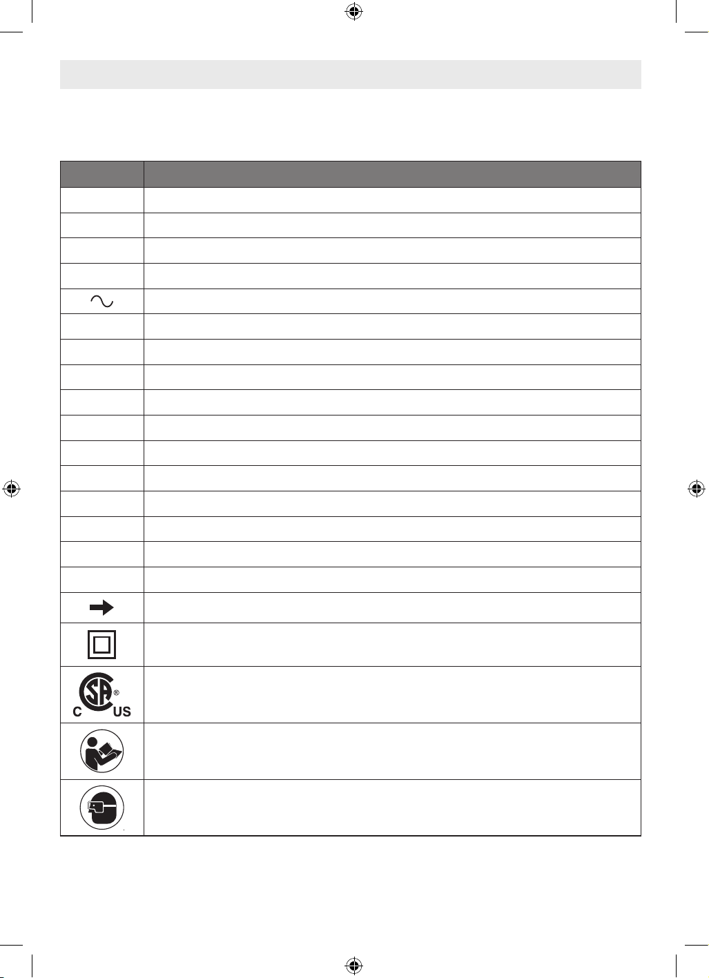
Symboles
Important : Certains des symboles suivants peuvent être utilisés sur votre outil. Veuillez les étudier et apprendre leur
signification. L’interprétation correcte de ces symboles vous aidera à mieux utiliser votre outil et à vous en servir plus
efficacement et en toute sécurité.
Symbole Désignation / Explication
V Volts (tension)
A Ampères (courant)
Hz Hertz (fréquence)
W Watt (puissance)
Courant alternatif (type ou caractéristique du courant)
lb Livres (poids)
kg Kilogrammes (poids)
ft Pieds (longueur)
in Pouces (longueur)
m Mètre (longueur)
cm Centimètre (longueur)
mm Millimètres (longueur)
F Fahrenheit (température)
C Celsius (température)
n0 Vitesse à vide (vitesse de rotation à vide)
RPM Révolutions par minute (vitesse)
Flèche (action dans le sens de la flèche)
Construction de classe II (désigne des outils de construction à double isolation)
Ce symbole indique que cet outil est répertorié par la Canadian Standards Association, et qu’il est
conforme aux normes des États-Unis et du Canada.
Alerte l’utilisateur pour lire le mode d’emploi.
Alerte l’utilisateur pour lui demander de porter un dispositif de protection des yeux.
16099221WG GLF55-25 OSI Final 20250228.indd 2816099221WG GLF55-25 OSI Final 20250228.indd 28 2/28/2025 8:49:29 AM2/28/2025 8:49:29 AM

29
Symboles
Important : Certains des symboles suivants peuvent être utilisés sur votre outil. Veuillez les étudier et apprendre leur
signification. L’interprétation correcte de ces symboles vous aidera à mieux utiliser votre outil et à vous en servir plus
efficacement et en toute sécurité.
Symbole Désignation / Explication
Alerte l’utilisateur pour porter des protecteurs d’oreilles
Alerte l’utilisateur pour porter une protection respiratoire
Fait savoir à l’utilisateur qu’il doit porter des protections oculaires, respiratoires et auditives.
Spécifications
Numéro de modèle GLF55-25
Courant nominal 4.3 A
Vitesse à vide 33,000 RPM
Taille max. de la fraise 1-1/8 po
Taille de la douille 1/4 po
16099221WG GLF55-25 OSI Final 20250228.indd 2916099221WG GLF55-25 OSI Final 20250228.indd 29 2/28/2025 8:49:29 AM2/28/2025 8:49:29 AM
30
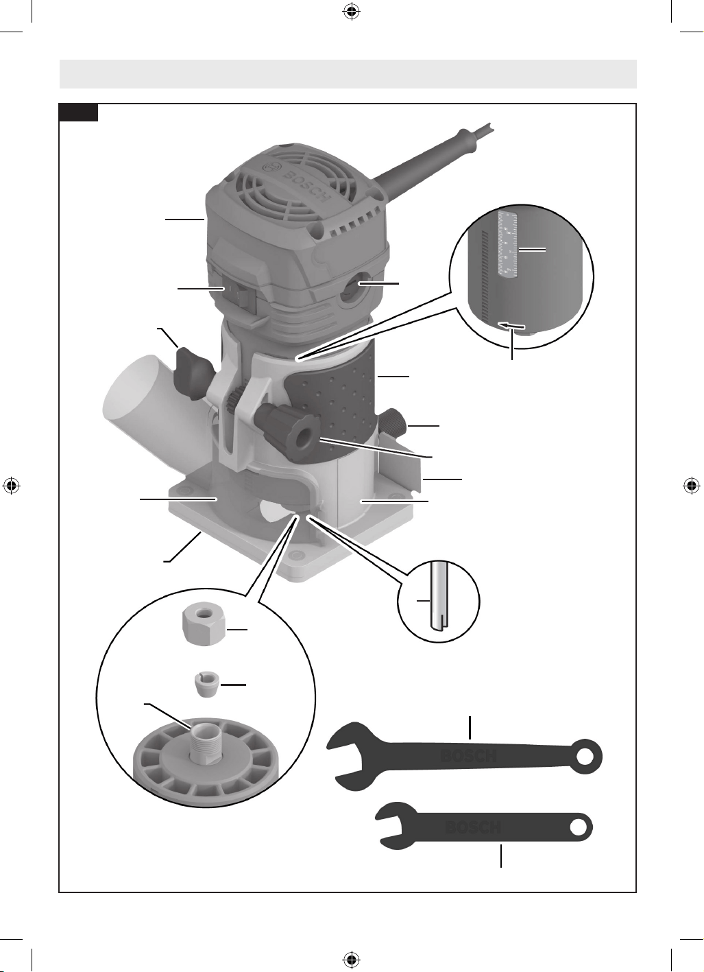
Familiarisez-vous avec votre ébouteuse pour coupe de finition GLF55-25.
2
1
6
11
15
14
19
16
8
8
13
3
7
18
17
4
5
12
9
10
Fig. 1
16099221WG GLF55-25 OSI Final 20250228.indd 3016099221WG GLF55-25 OSI Final 20250228.indd 30 2/28/2025 8:49:29 AM2/28/2025 8:49:29 AM
31
Familiarisez-vous avec votre ébouteuse pour coupe de finition GLF55-25.
* Vendu séparément.
1 Interrupteur de marche/arrêt
2 Ébouteuse pour coupe de finition
3 Poignée (surface de préhension isolée)
4 Vis à oreilles pour accessoires arrière
5 Dispositif de protection contre les copeaux
6 Bouton de serrage
7 Bouton de réglage de la profondeur
8 Échelle de profondeur
9 Fraise*
10 Sens de rotation
11 Embase ronde
12 Base fixe
13 Support de balai de carbone
14 Douille
15 Écrou de douille
16 Broche
17 Clé de verrouillage de la broche (10 mm)
18 Clé pour écrou de douille (17 mm)
19 Hotte d’extraction de la poussière (GLF001)
20 Guide de gabarit
21 Guide à bord droit (PR102)
22 Boulon à oreilles pour guide à bord droit
23 Guide pour les douilles/rouleaux à base fixe
(PR003)
24 Écrou à oreilles pour l’alignement horizontal du
guide du rouleau/de la douille (en bas)
25 Écrou à oreilles pour l’alignement horizontal du
guide du rouleau/de la douille (à l’arrière)
26 Douilles/rouleaux
20
22
24
21
23
25
26
Fig. 2
16099221WG GLF55-25 OSI Final 20250228.indd 3116099221WG GLF55-25 OSI Final 20250228.indd 31 2/28/2025 8:49:29 AM2/28/2025 8:49:29 AM
32
Assemblage et réglages
Fraises
Utilisez uniquement des
fraises dont le diamètre
de la tige correspond à celui de la douille installée.
L’utilisation d’une fraise dont la tige est plus petite peut
entraîner le détachement de la fraise pendant son
fonctionnement, et elle risquerait ainsi de devenir un
projectile.
N’utilisez jamais des
fraises à des vitesses su-
périeures à leur vitesse nominale maximale. Des fraises
fonctionnant à une vitesse supérieure à leur vitesse nominale
risqueraient de se casser et d’être projetées dans l’air.
Sélection des fraises
Cet outil est conçu pour des applications de toupillage très
variées qui utilisent des fraises à tiges de 1/4 po. Citons
notamment des applications de travail du bois telles que le
découpage des bords, le traçage de rainures et la fabrication
de supports de signalétique. Cette toupie est également idéale
pour le découpage de stratifiés, de composés phénoliques et
d’autres matériaux ayant été collés sur un substrat et ayant
typiquement une épaisseur d’environ 3 mm / 1/8 po au-
dessus du substrat. Des fraises très variées avec des profils
différents sont disponibles en tant qu’accessoires. N’utilisez
que des fraises de bonne qualité.
Remarque : Bien que la fraise puisse être installée et retirée de
l’affleureuse portative lorsqu’elle est installée dans une base,
il est recommandé de retirer l’affleureuse portative de la base
avant d’installer une fraise. Voir la section correspondant à la
base sélectionnée qui est utilisée pour apprendre comment
séparer l’affleureuse portative de la base.
Installation/retrait d’une fraise
(Fig. 3, Fig. 4)
N’utilisez pas de fraise
d’un diamètre supérieur
à 1-1/8 po. L’utilisation d’une fraise de diamètre supérieur à
1-1/8 po pourrait entraîner des blessures.
Ne serrez pas la douille sans
fraise. Le serrage de la douille
sans qu’une fraise soit insérée pourrait endommager l’outil.
Avant de sécuriser la fraise 9 sélectionnée, assurez-vous que
la broche 16, la douille 14, l’écrou de fixation de la douille
15 et la tige de la fraise sont propres. La tige de la fraise doit
être droite, non endommagée et d’une taille appropriée par
rapport à la douille 14.
1. Suivez les étapes de la section intitulée « Installation et
retrait de l’ébouteuse dans la base fixe » à la page 33
pour retirer l’ébouteuse 2 de la base fixe 12.
2. À l’aide de l’extrémité de la clé de verrouillage de la
broche 17, maintenez la broche 16 en place .
3. Utilisez la clé de serrage de l’écrou de fixation de la douille
18 pour desserrer l’écrou de fixation de la douille 15 dans
le sens inverse des aiguilles d’une montre .
4. Si nécessaire, retirez la fraise 9 installée.
5. Insérez la tige de la fraise 9 dans la douille 14 autant que
cela est possible, puis faites sortir la tige jusqu’à ce que
les fraises soient à entre 1/8 po et 1/4 po environ de la
face de l’écrou de fixation de la douille 15.
6. Une fois que la fraise à ébouter 9 aura été insérée et que la
clé de verrouillage de la broche 17 maintiendra la broche
16 en place , utilisez la clé de verrouillage de l’écrou de
fixation de la douille 18 pour serrer fermement l’écrou de
fixation de la douille 15 dans le sens des aiguilles d’une
montre .
Débranchez la fiche de la prise de courant avant de procéder à des réglages ou des
changements d’accessoires, ou avant de ranger des outils électriques. De telles mesures
de sécurité préventives réduisent le risque de déclenchement accidentel de l’outil électrique.
15
18
17
Fig. 3
18
15
9
17
Fig. 4
16099221WG GLF55-25 OSI Final 20250228.indd 3216099221WG GLF55-25 OSI Final 20250228.indd 32 2/28/2025 8:49:29 AM2/28/2025 8:49:29 AM
33
Remarque : Pour faire en sorte que la fraise 9 accroche de
façon adéquate et pour réduire au minimum le risque de
rotation excentrée, la tige de la fraise 9 doit être insérée au
moins sur 5/8 po.
Remplacement de la douille
(Fig. 3, Fig. 4, Fig. 5)
Cet outil comprend une douille de 1/4 po préinstallée 14, à
l’intérieur de l’écrou de fixation de la douille 15, qui doit être
utilisée avec une tige d’accessoire de 1/4 po de diamètre.
Pour remplacer l’ensemble douille 14 :
1. Retirez l’ébouteuse 2 de la base fixe 12 comme décrit
dans la section intitulée « Installation et retrait de
l’ébouteuse dans la base fixe » ci-dessous.
2. À l’aide de la clé de verrouillage de la broche 17,
maintenez la broche 16 en place.
3. Utilisez la clé de serrage de l’écrou de fixation de la douille
18 pour desserrer l’écrou de fixation de la douille 15 dans
le sens inverse des aiguilles d’une montre.
4. Dévissez et retirez l’ensemble d’écrou de fixation de la
douille 15.
5. Assurez-vous que les filets de la broche 16 sont propres
et que la douille 14 est correctement installée dans
l’écrou de fixation de la douille 15.
6. Vissez à la main le nouvel ensemble de douille 14 sur la
broche 16.
Installation et retrait de l’ébouteuse dans la
base fixe
(Fig. 6)
Installation de l’ébouteuse sur la base fixe
Desserrez le mécanisme de serrage de la base fixe 12 en
tournant le bouton de serrage 6 dans le sens inverse des
aiguilles d’une montre.
1. Alignez à la fois l’ébouteuse 2 et la base fixe 12 de
manière à ce qu’elles soient orientées vers l’avant.
2. Faites glisser l’ébouteuse 2 dans la base fixe 12 .
3. Utilisez le bouton de réglage de la profondeur 7 pour
atteindre précisément la profondeur souhaitée sur
l’échelle de profondeur 8 .
4. Serrez fermement le bouton de serrage 6 en le tournant
dans le sens des aiguilles d’une montre pour sécuriser
l’ébouteuse 2 en place.
Retrait de l’ébouteuse de la base fixe
1. Desserrez le mécanisme de serrage de la base fixe 12 en
tournant le bouton de serrage 6 dans le sens inverse des
aiguilles d’une montre .
2. Faites glisser la l’affleureuse portative 2 dans la base fixe
12 .
Assemblage et réglages
15
16
14
Fig. 5
6
7
12
2
8
Fig. 6
16099221WG GLF55-25 OSI Final 20250228.indd 3316099221WG GLF55-25 OSI Final 20250228.indd 33 2/28/2025 8:49:30 AM2/28/2025 8:49:30 AM
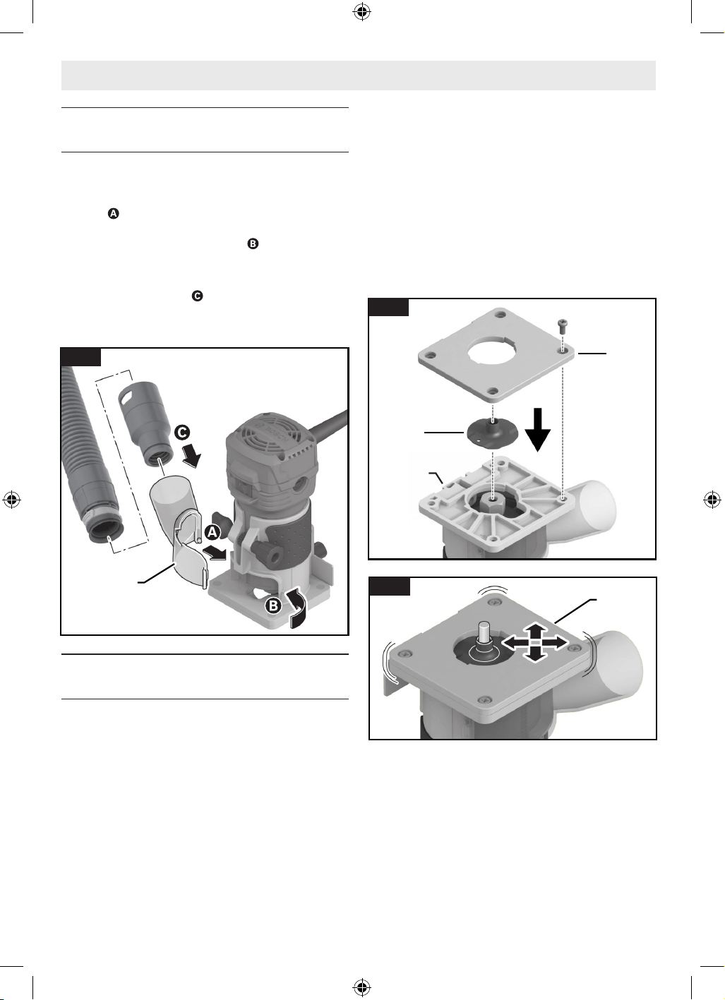
34
Assemblage et réglages
Installation de la hotte d’extraction de la
poussière (GLF001) (accessoire en option)
(Fig. 7)
1. Placez la petite languette située en bas à gauche de la
hotte d’extraction de poussière 19 dans la fente de la
base , puis tournez la hotte 19 vers la base jusqu’à ce
que la languette du côté droit s’enclenche dans la fente
située sur le côté droit de la base ; il y aura alors un
déclic audible.
2. Raccordez la hotte à l’aspirateur à l’aide d’une buse à
ajustement par friction .
Pour retirer la hotte d’extraction de la poussière 19, saisissez
le côté de l’adaptateur et tirez-le vers l’avant.
Installation du guide de gabarit (accessoire
en option)
(Fig. 8, Fig. 9)
1. Dévissez les quatre vis situées sous l’embase 11, et
retirez l’embase 11.
2. Alignez la configuration des fentes et insérez le guide de
gabarit 20 dans la base fixe 12.
3. Revissez sans serrer l’embase 11 sur la base fixe 12.
Assurez-vous que l’embase 11 peut toujours se déplacer
librement.
4. Alignez l’embase 11 de manière à ce que le guide de
gabarit 20 soit centré sur l’ouverture de l’embase 11.
Remarque : Le dispositif de centrage en option RA1151
peut être utilisé pour centrer précisément le guide de
gabarit ou l’embase.
5. Maintenez l’embase 11 dans cette position et serrez
fermement les vis de fixation.
6. Installez la fraise à ébouter souhaitée 9. Voir la section
intitulée « Installation/retrait d’une fraise » à la page
32.
Remarque : L’ébouteuse 2 doit rester installée sur la base
fixe 12 lors de l’installation d’une fraise à ébouter 9 et de
l’utilisation d’un guide de gabarit 20.
19
CLICK!
CLICK!
Fig. 7
11
20
12
Fig. 8
11
Fig. 9
16099221WG GLF55-25 OSI Final 20250228.indd 3416099221WG GLF55-25 OSI Final 20250228.indd 34 2/28/2025 8:49:30 AM2/28/2025 8:49:30 AM
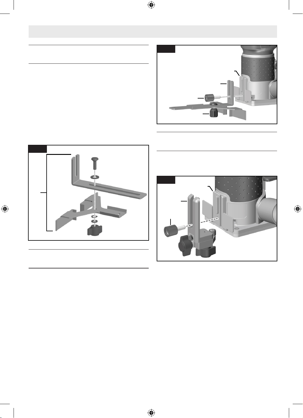
35
Assemblage et réglages
Assemblage du guide de chant (accessoire en
option)
(Fig. 10)
Le guide de chant 21 est un accessoire en option qui guidera
l’ébouteuse parallèlement à un bord droit.
Le guide de chant 21 est fourni en deux parties qui doivent
être assujetties l’une à l’autre par un boulon, un écrou à
oreilles et des rondelles.
Pour assembler le guide de chant 21 :
1. Positionnez la plaque de guidage sur le guide de chant.
2. Fixez les deux parties ensemble avec le boulon, l’écrou à
oreilles et les rondelles.
Attachement du guide de chant (accessoire
en option)
(Fig. 11)
1. Attachez le guide de chant 21 à la base fixe 12 à l’aide de
la vis de serrage pour accessoire arrière 4.
2. Utilisez le boulon à oreilles pour le guide de chant 22 afin
de régler la profondeur de butée requise.
Attachement du guide de la douille/du
rouleau (PR003) (accessoire en option)
(Fig. 12)
1. Attachez le guide de la douille/du rouleau 23 à la base fixe
12 à l’aide de la vis de serrage pour accessoire arrière 4.
21
Fig. 10
12
22
4
21
Fig. 11
12
4
23
Fig. 12
16099221WG GLF55-25 OSI Final 20250228.indd 3516099221WG GLF55-25 OSI Final 20250228.indd 35 2/28/2025 8:49:30 AM2/28/2025 8:49:30 AM
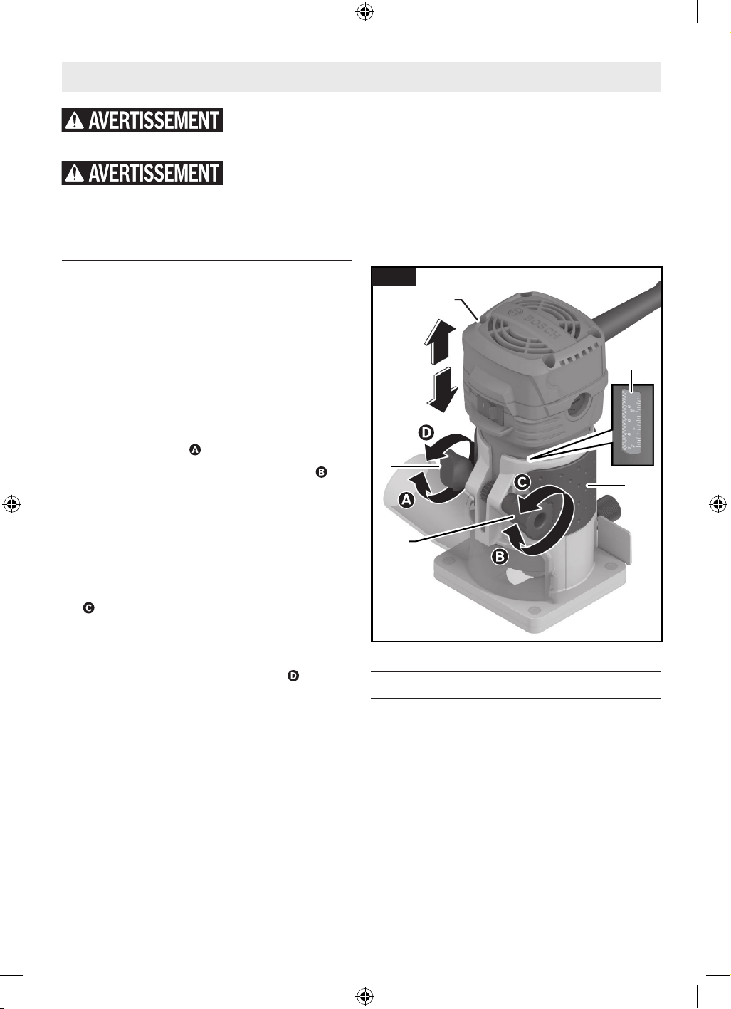
36
Fonctionnement de l'outil
Réglage de la profondeur de coupe
(Fig. 13)
1. Installez l’affleureuse portative souhaitée 9. Voir la
section intitulée « Installation/retrait d’une fraise » à la
page 32.
2. Faites glisser l’ébouteuse pour coupe de finition 2 dans
la base fixe 12.
3. Placez l’ensemble d’affleureuse/de base sur la pièce à
travailler.
4. Desserrez le mécanisme de fixation de la base fixe 12 en
tournant le bouton de serrage 6 dans le sens inverse des
aiguilles d’une montre .
5. Tournez le bouton de réglage de la profondeur 7 pour
abaisser lentement l’ébouteuse jusqu’à ce que la fraise à
ébouter entre en contact avec l’ouvrage.
6. Notez la valeur affichée sur l’échelle de profondeur 8 et
ajoutez la profondeur de coupe désirée à cette valeur
pour déterminer la valeur d’échelle ciblée.
7. Soulevez l’ensemble d’ébouteuse/de base de l’ouvrage,
et poussez le bouton de réglage de la profondeur 7
pour abaisser ou élever l’ébouteuse pour coupe de
finition 2 dans la base jusqu’à ce que la valeur cible de
l’échelle soit atteinte.
8. Serrez fermement le bouton de serrage 6 en le tournant
dans le sens des aiguilles d’une montre pour fixer
l’ébouteuse pour coupe de finition 2 en place.
9. Assurez-vous que l’affleureuse portative 2 est bien fixée
dans la base.
10. Effectuez une coupe d’essai pour vérifier que
l’affleureuse portative 2 est réglée à la profondeur
souhaitée.
Coupes profondes
Pour les coupes profondes, effectuez plusieurs coupes
progressivement plus profondes en commençant par une
profondeur et en effectuant ensuite plusieurs passes, en
augmentant la profondeur de coupe à chaque passe. Pour
vous assurer que vos réglages de profondeur sont corrects,
vous pouvez effectuer des coupes d’essai dans des chutes de
matériau avant de commencer le travail réel.
Utilisation de l’affleureuse portative
(Fig. 14)
Interrupteur de marche/arrêt
Votre outil peut être mis en marche ou arrêté à l’aide de
l’interrupteur de marche/arrêt 1 situé sur le carter du moteur.
Un côté de l’interrupteur comporte un repère « I » pour «
Marche », et l’autre côté de l’interrupteur comporte un repère
« O » pour « Arrêt ».
MISE DE L’OUTIL SOUS TENSION : Faites glisser le
commutateur 1 vers la gauche ; le marquage « I » sera alors
révélé.
Débranchez la fiche de la prise de courant avant de procéder à des réglages ou des
changements d’accessoires, ou avant de ranger des outils électriques. De telles mesures
de sécurité préventives réduisent le risque de déclenchement accidentel de l’outil électrique.
Utilisez des équipe-ments de sécurité per-sonnelle. Portez toujours une protection
oculaire. Le port d’équipements de sécurité tels que des masques antipoussières, des
chaussures de sécurité antidérapantes, des casques de chantier et des protecteurs d’oreilles dans des conditions appropriées
réduira le risque de blessure corporelle.
6
7
12
2
8
Fig. 13
16099221WG GLF55-25 OSI Final 20250228.indd 3616099221WG GLF55-25 OSI Final 20250228.indd 36 2/28/2025 8:49:30 AM2/28/2025 8:49:30 AM
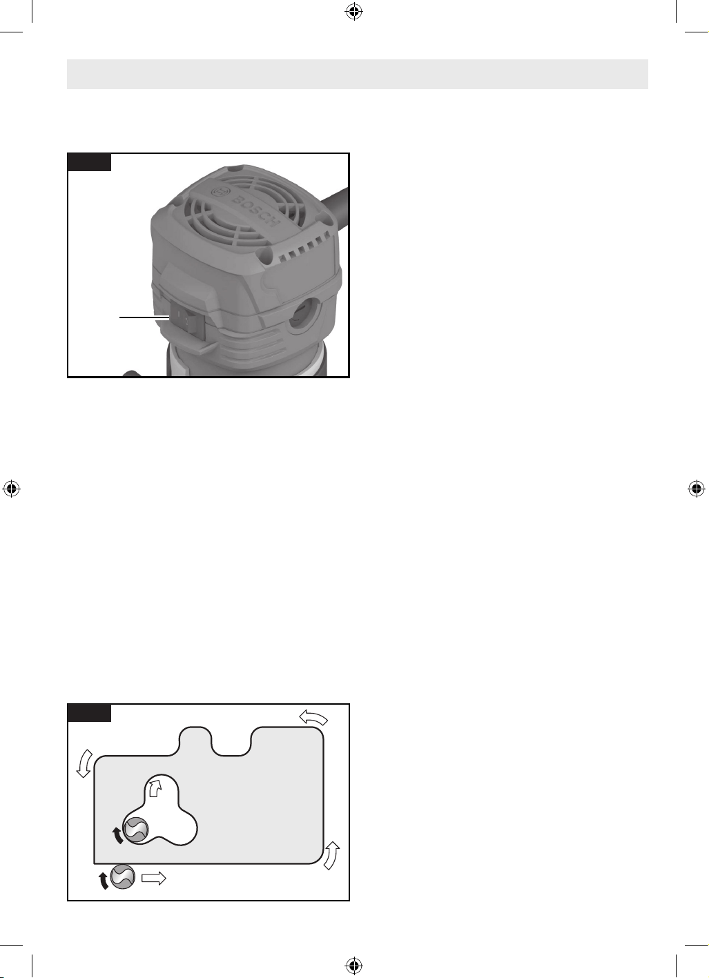
37
MISE DE L’OUTIL HORS TENSION : Faites glisser le
commutateur 1 vers la droite ; le marquage « O » sera alors
révélé.
Protection contre le redémarrage
Pour mettre l’ébouteuse en marche, elle doit être activée
lorsqu’elle est branchée sur la source d’alimentation mais en
position hors tension.
Le système de protection contre le redémarrage contribue à
empêcher les démarrages accidentels après une interruption
de l’alimentation électrique, p. ex. si l’outil a été débranché
avec l’interrupteur verrouillé en position de marche. Pour faire
redémarrer l’outil, tournez l’interrupteur de marche/arrêt 1
pour le mettre dans la position d’arrêt, puis remettez l’outil en
marche.
Alimentation de l’affleureuse portative
(Fig. 15)
Cette section explique comment alimenter correctement
l’affleureuse portative pendant son fonctionnement.
Veillez à lire les sections correspondantes pour prendre
connaissance des étapes opérationnelles détaillées pour
chaque type de base.
Comme on peut le voir depuis le haut de l’affleureuse
portative, la fraise tourne dans le sens des aiguilles d’une
montre, et les bords de coupe de la fraise sont positionnés
de manière à couper le plus efficacement possible dans la
pièce à travailler. Par conséquent, la coupe la plus efficace
est effectuée en faisant avancer l’affleureuse portative de
telle manière que la fraise tourne en avançant dans la pièce à
travailler, et non en s’en éloignant. La figure suivante montre
l’alimentation appropriée pour diverses coupes. La vitesse de
l’alimentation dépend de la dureté du matériau à couper et de
la taille de la coupe. Pour certains matériaux, il est préférable
de réaliser plusieurs coupes de plus en plus profondes.
Si l’affleureuse portative est difficile à contrôler, si elle
surchauffe, si elle tourne très lentement ou si elle produit une
coupe imparfaite, considérez les causes possibles suivantes :
• Direction de l’alimentation incorrecte – difficile à
contrôler.
• Alimentation trop rapide – surcharge du moteur.
• Fraise émoussée – surcharge du moteur.
• Coupe de trop grande envergure pour une seule passe –
surcharge du moteur.
• Alimentation trop lente – laisse des marques de brûlures
causées par le frottement sur la pièce à travailler.
L’alimentation doit se faire en douceur et de manière uniforme
(ne pas forcer).
La pratique et l’expérience vous aideront à reconnaître
les sons et le ressenti de l’affleureuse portative quand elle
fonctionne de façon optimisée.
Guidage de l’affleureuse portative
(Fig. 16)
L’affleureuse peut être guidée à travers la pièce à travailler de
plusieurs façons différentes. La méthode utilisée dépendra
bien entendu des exigences du travail particulier à effectuer et
de la commodité. Pour les opérations de toupillage telles que
le rainurage ou la coupe de feuillures, il est souvent nécessaire
de guider l’outil sur une ligne parallèle à une arête droite. Une
méthode permettant d’obtenir une coupe droite consiste
à fixer solidement une planche ou un autre matériau à bord
droit sur la surface de travail et à guider le bord de l’embase
de l’affleureuse le long de cette trajectoire.
Assurez-vous toujours que l’ébouteuse pour coupe de finition
n’est pas en contact avec l’ouvrage lorsque vous la mettez
sous tension ou hors tension. Mettez l’ouvrage en contact
avec l’ébouteuse après que celle-ci aura atteint sa vitesse de
Fonctionnement de l'outil
1
Fig. 14
Pièce
Sens de l’avance
Fig. 15
16099221WG GLF55-25 OSI Final 20250228.indd 3716099221WG GLF55-25 OSI Final 20250228.indd 37 2/28/2025 8:49:30 AM2/28/2025 8:49:30 AM
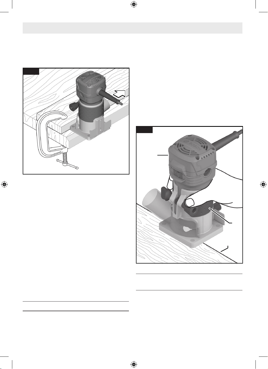
38
fonctionnement normale, et séparez-la de l’ouvrage avant de
la mettre hors tension. L’utilisation de l’ébouteuse de cette
manière prolongera la durée de vie de l’interrupteur et du
moteur, et elle améliorera considérablement la qualité de
votre travail.
Vitesse d’alimentation
Lors du défonçage ou de travaux connexes dans le bois et
le plastique, les meilleures finitions seront obtenues si la
profondeur de coupe et la vitesse d’alimentation sont réglées
de manière à ce que le moteur fonctionne à grande vitesse.
Alimentez l’affleureuse portative à un rythme modéré. Les
matériaux tendres nécessitent une alimentation à une vitesse
plus rapide que les matériaux durs. L’affleureuse risque de
caler si elle est utilisée de façon inappropriée ou en état de
surcharge. Réduisez la vitesse d’alimentation pour ne pas
risquer d’endommager l’outil. Assurez-vous toujours que
l’écrou de fixation de la douille est bien serré avant de l’utiliser.
Utilisez toujours des fraises ayant la longueur de coupe la plus
courte nécessaire pour produire la coupe souhaitée. Ceci
permet de minimiser les faux-ronds de la fraise et le broutage.
Il peut être nécessaire d’effectuer la coupe en plusieurs passes
avec des réglages progressivement plus profonds pour ne pas
risquer de surcharger le moteur. Si la fraise coupe librement
et si le moteur ne ralentit pas, la profondeur de coupe est
généralement correcte.
Utilisation une base fixe
(Fig. 17)
1. Installez la fraise 9. Voir la section intitulée « Installation/
retrait d’une fraise » à la page 32.
Fonctionnement de l'outil
2. Ajustez la profondeur de coupe. Voir la section intitulée
« Réglage de la profondeur de coupe » à la page 36.
3. Branchez l’ébouteuse 2 dans la source d’alimentation.
4. Saisissez fermement l’ébouteuse 2 par la surface de
préhension isolée 3.
5. Mettez l’ébouteuse 2 sous tension. Voir la section
intitulée « Interrupteur de marche/arrêt » à la page 36.
6. Faites pénétrer l’ébouteuse 2 dans la pièce à travailler.
Voir la section intitulée « Alimentation de l’affleureuse
portative » à la page 37.
7. Une fois le toupillage terminé, mettez l’ébouteuse 2
hors tension. Voir la section intitulée « Interrupteur de
marche/arrêt » à la page 36.
Utilisation du guide de chant (accessoire en
option)
(Fig. 18)
Le guide à bord droit 21 est un accessoire en option qui
guidera l’affleureuse portative parallèlement à un bord droit.
Le guide comporte une échelle permettant de positionner le
guide à bord droit de façon précise par rapport à la fraise. Une
fois le guide installé et ajusté, vous pouvez faire avancer la
fraise normalement, en gardant toujours le guide en contact
avec le bord de la pièce à travailler.
2
3
Pièce
Pièce
Bord de
Bord de
la pièce à
la pièce à
travailler
travailler
Fig. 17
Fig. 16
16099221WG GLF55-25 OSI Final 20250228.indd 3816099221WG GLF55-25 OSI Final 20250228.indd 38 2/28/2025 8:49:31 AM2/28/2025 8:49:31 AM
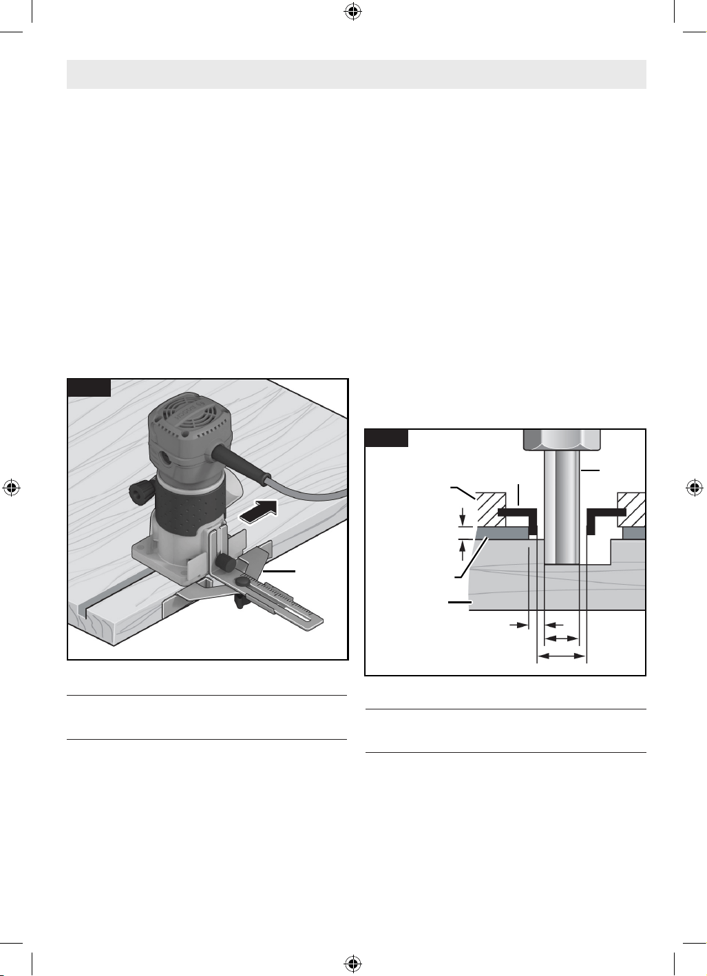
39
Le guide de la toupie peut également être positionné
directement en dessous de la base de la toupie pour les
opérations dans lesquelles une coupe est nécessaire sur le
bord de la pièce à travailler, ou près de celle-ci, comme pour
égaliser les extrémités de planches d’une terrasse. Pour des
instructions complètes sur l’installation et le fonctionnement,
veuillez vous référer aux instructions fournies avec cet
accessoire.
Pour utiliser le guide de chant 21 :
1. Suivez les étapes décrites dans les sections intitulées
« Assemblage du guide de chant (accessoire en
option) » et « Attachement du guide de chant (accessoire
en option) » à la page 35 pour assembler et attacher le
guide de chant 21.
2. Une fois le guide installé et ajusté, vous pouvez faire
avancer la fraise normalement, en gardant toujours le
guide en contact avec le bord de l’ouvrage.
Utilisation du guide de gabarit (accessoire en
option)
(Fig. 19)
Lors de l’utilisation d’un guide de gabarit 20, n’utilisez que des
fraises à ébouter 9 avec des éléments tranchants (a) dont le
diamètre est inférieur d’au moins 1/16 po au diamètre interne
du guide de gabarit (b).
Le guide de gabarit 20 permet de transférer les contours
des gabarits ou des modèles sur l’ouvrage. Le gabarit devra
être créé de façon à compenser la distance entre la fraise à
ébouter 9 et le diamètre extérieur (DE) du guide de gabarit
20 (la « compensation ») étant donné que la taille de l’ouvrage
Fonctionnement de l'outil
final sera différente de celle du modèle de gabarit par cette
distance en raison de la position de la fraise.
Sélectionnez le guide de gabarit 20 adapté à l’épaisseur
du gabarit ou du modèle. En raison de la hauteur saillante
du guide de gabarit 20, le gabarit doit avoir une épaisseur
minimale de 8 mm (0,315 po).
Pour utiliser le guide de gabarit 20 :
1. Attachez le guide de gabarit 20 à l’ébouteuse en suivant
les instructions décrites dans la section intitulée
« Installation du guide de gabarit (accessoire en option) »
à la page 34.
2. Mettez l’outil électrique avec le guide de gabarit 20 sur
le gabarit.
3. Déplacez l’outil électrique avec le guide de gabarit 20
faisant saillie le long du gabarit, en appliquant une
pression sur les côtés.
Remarque : Mesurez et vérifiez le diamètre interne réel (b), le
décalage et la hauteur de saillie du guide de gabarit 20 avant
de l’utiliser.
Utilisation de fraises autopilotées (vendu
séparément)
(Fig. 20)
Les fraises auto-pilotées sont dotées d’une pointe ronde
intégrée ou d’un roulement à billes qui s’appuie sur la surface
de travail au-dessus ou au-dessous de la fraise pour contrôler
la profondeur de coupe horizontale. Lors de l’utilisation
de ces fraises, il n’est pas nécessaire d’utiliser le guide de
rouleau ou le guide à bord droit. Lors du guidage contre une
surface stratifiée, utilisez de la cire ou un autre lubrifiant, et
n’appliquez pas de pression excessive ; sinon, l’extrémité
21
Fig. 18
9
5/16 po
(8 mm)
a
b
a < b
Compensation
20
Gabarit
11
Pièce
Pièce
Fig. 19
16099221WG GLF55-25 OSI Final 20250228.indd 3916099221WG GLF55-25 OSI Final 20250228.indd 39 2/28/2025 8:49:31 AM2/28/2025 8:49:31 AM
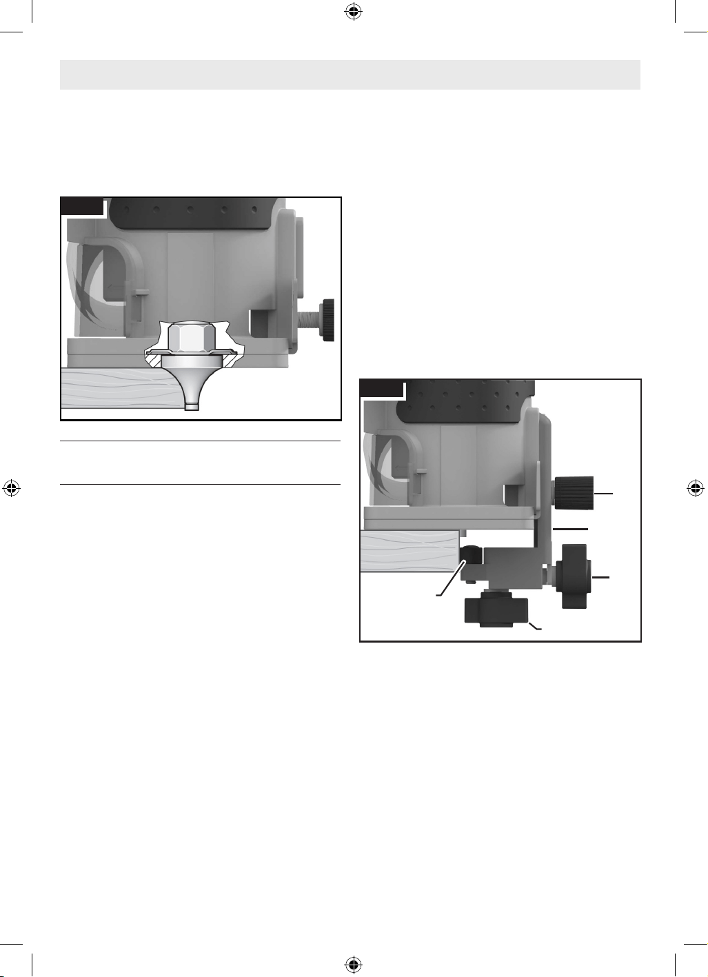
40
pilotée risquerait d’abîmer la pièce à travailler. Les pilotes
de roulements à billes doivent être maintenus propres et
exempts de colle ou d’autres résidus. Les roulements à billes
des fraises sont scellés et lubrifiés en permanence. Ils doivent
être remplacés lorsqu’ils ne tournent plus librement afin de ne
pas risquer d’endommager la surface de travail.
Utilisation du guide de la douille/du rouleau
(PR003) (accessoire en option)
(Fig. 21)
Le guide pour les douilles/rouleaux à base fixe en option 23
est utilisé dans des opérations de formation ou de taille de
bords avec des fraises non pilotées et non porteuses.
Suivez les étapes de la section intitulée « Attachement du
guide de la douille/du rouleau (PR003) (accessoire en
option) » à la page 35 pour installer le guide.
Réglage vertical du guide pour les douilles/
rouleaux
(Fig. 21)
1. Desserrez la vis de serrage pour accessoire arrière 4 et
ajustez vers le haut ou vers le bas suivant les besoins pour
permettre au guide de la douille/du rouleau à base fixe 23
de rouler sur la surface de guidage prévue.
2. Serrez la vis de serrage pour accessoire arrière 4.
Réglage horizontal du guide pour les douilles/
rouleaux
(Fig. 21)
Que vous fassiez des coupes droites ou en biseau, la largeur
du matériau retiré est déterminée par la distance entre l’avant
de l’élément tranchant de la fraise et l’avant de la douille/du
rouleau.
Ajustez l’avant du rouleau/de la douille de la façon suivante :
1. Desserrez l’écrou à oreilles pour alignement horizontal
(en bas) 24.
2. Faites tourner l’écrou à oreilles pour alignement
horizontal (à l’arrière) 25 pour déplacer le rouleau/
la douille 26 vers l’intérieur ou vers l’extérieur afin de
produire le montant d’exposition à l’élément tranchant
nécessaire pour découper le stratifié au ras de la surface
de guidage ou pour produire le biseau désiré.
3. Assurez-vous que la fraise 23 dépasse le haut du guide
pour les douilles/rouleaux d’au moins 1/8 po (3 mm)
pour éviter tout risque d’endommagement.
4. Serrez l’écrou à oreilles pour alignement horizontal (en
bas) 24.
5. Effectuez une coupe d’essai pour vérifier le réglage, et
réajustez si nécessaire.
Utilisation du guide pour les douilles/rouleaux
Une fois le guide installé et ajusté, vous pouvez faire avancer
la fraise normalement, en gardant toujours le guide en contact
avec le bord de la pièce à travailler.
Pour maintenir une largeur de coupe constante, un angle
constant doit être maintenu entre l’affleureuse et la pièce à
travailler.
Fonctionnement de l'outil
Fig. 20
4
23
24
25
26
Fig. 21
16099221WG GLF55-25 OSI Final 20250228.indd 4016099221WG GLF55-25 OSI Final 20250228.indd 40 2/28/2025 8:49:31 AM2/28/2025 8:49:31 AM

41
Nettoyage
Certains agents de nettoyage et solvants peuvent endommager
les pièces en plastique. Citons notamment : l’essence, le
tétrachlorure de carbone, les solvants de nettoyage chlorés,
l’ammoniac et les détergents ménagers contenant de
l’ammoniac.
Dépoussiérez périodiquement l’outil en l’essuyant avec un
chiffon propre ou en utilisant de l’air comprimé à l’intérieur de
la base et du moteur, ainsi que du système de réglage précis
de la profondeur.
Enlevez la poussière et les débris de toutes les bouches
d’aération. Maintenez l’affleureuse portative propre, sèche et
exempte d’huile ou de graisse. N’utilisez que du savon doux
et un chiffon humide pour nettoyer l’affleureuse portative, car
certains produits de nettoyage et solvants sont nocifs pour
les plastiques et autres pièces isolées. Il s’agit notamment
de l’essence, de la térébenthine, du diluant pour laque, du
diluant pour peinture, des solvants de nettoyage chlorés,
de l’ammoniaque et des détergents ménagers contenant de
l’ammoniaque. N’utilisez jamais de solvants inflammables ou
combustibles à proximité des outils.
Rangement et maintenance
Conservez l’affleureuse portative et ses accessoires dans un
endroit frais et sec, et assurez-vous qu’ils ne vont pas geler.
Avant toute utilisation, vérifiez que les fraises ne présentent
pas de fissures ou de fractures, et ne les utilisez pas si vous
suspectez des dommages.
Entretien
Maintenance générale
Maintenez votre ébouteuse et vos accessoires en bon état
de fonctionnement en adoptant un programme d’entretien
régulier. Inspectez votre ébouteuse pour vous assurer que
les pièces en mouvement ne font pas un bruit excessif et
qu’elles ne se coincent pas, qu’il n’y a pas de pièces cassées
ou qu’il n’existe aucune autre situation pouvant affecter le
fonctionnement de l’ébouteuse.
Service
Faites entretenir votre outil électrique par un réparateur
compétent n’utilisant que des pièces de rechange identiques.
Ceci assurera le maintien de la sécurité de l’outil électrique.
Lubrification de l’outil
Votre outil Bosch a été lubrifié correctement et est prêt à
l’emploi. Il est recommandé que les outils comportant des
engrenages soient graissé à nouveau avec un lubrifiant spécial
pour engrenages lors de chaque remplacement des balais.
Balais ou charbons
Les balais (ou charbons) et le collecteur de votre outil
ont été conçus pour apporter de nombreuses heures de
fonctionnement fiable. Pour maintenir le rendement du
moteur à son maximum, nous vous conseillons de contrôler
les balais tous les deux à six mois. Il ne faut utiliser que des
balais de rechange Bosch d’origine et conçus pour votre outil.
Paliers et roulements
Tous les paliers et roulements de cet outil sont lubrifiés avec
une quantité suffisante de lubrifiant de haute qualité pour la
durée de vie de l’unité dans des conditions de fonctionnement
normales. Aucune autre lubrification n’est nécessaire.
Débranchez la fiche de la prise de courant avant de procéder à des réglages ou des
changements d’accessoires, ou avant de ranger des outils électriques. De telles mesures
de sécurité préventives réduisent le risque de déclenchement accidentel de l’outil électrique.
16099221WG GLF55-25 OSI Final 20250228.indd 4116099221WG GLF55-25 OSI Final 20250228.indd 41 2/28/2025 8:49:31 AM2/28/2025 8:49:31 AM
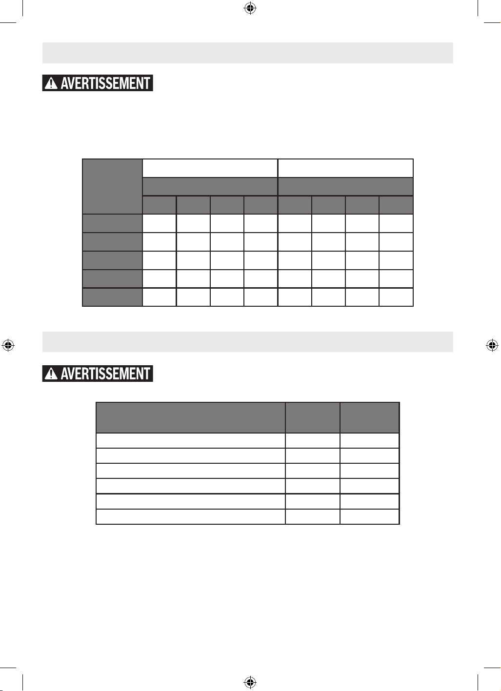
42
Cordons de rallonge
Accessoires
Si un cordon de rallonge s'avère nécessaire, vous devez utiliser un cordon avec
conducteurs de dimension adéquate pouvant porter le courant nécessaire à votre outil.
Ceci préviendra une chute excessive de tension, une perte de courant ou une surchauffe. Les outils mis à la terre doivent utiliser
des cordons de rallonge trifilaires pourvus de fiches à trois broches ainsi que des prises à trois broches.
REMARQUE : Plus le calibre est petit, plus le fil est gros.
Dimensions de rallonges recommandées pour outils 120 volts courant alternatif
Intensité
nominale de
l’outil
Calibre A.W.G. Calibre en mm2
Longueur en pieds Longueur en mètres
25 50 100 150 15 30 60 120
3-6 18 16 16 14 0.75 0.75 1.5 2.5
6-8 18 16 14 12 0.75 1.0 2.5 4.0
8-10 18 16 14 12 0.75 1.0 2.5 4.0
10-12 16 16 14 12 1.0 2.5 4.0 –
12-16 14 12 – – – – – –
N’utilisez pas d’attachements/d’accessoires autres que ceux qui sont spécifiés par
Bosch. L’utilisation d’attachements/d’accessoires non spécifiés pour une utilisation avec
l’outil décrit dans ce mode d’emploi peut entraîner des dommages à l’outil, des dommages matériels/ou des blessures.
Accessoire Inclus
Vendu
séparément
Guide à bord droit • •
Guide pour les douilles/rouleaux à base fixe (PR003) • •
Guide de gabarit • •
Hotte d’extraction de la poussière (GLF001) • •
Fraises autopilotées •
Fraises •
16099221WG GLF55-25 OSI Final 20250228.indd 4216099221WG GLF55-25 OSI Final 20250228.indd 42 2/28/2025 8:49:31 AM2/28/2025 8:49:31 AM
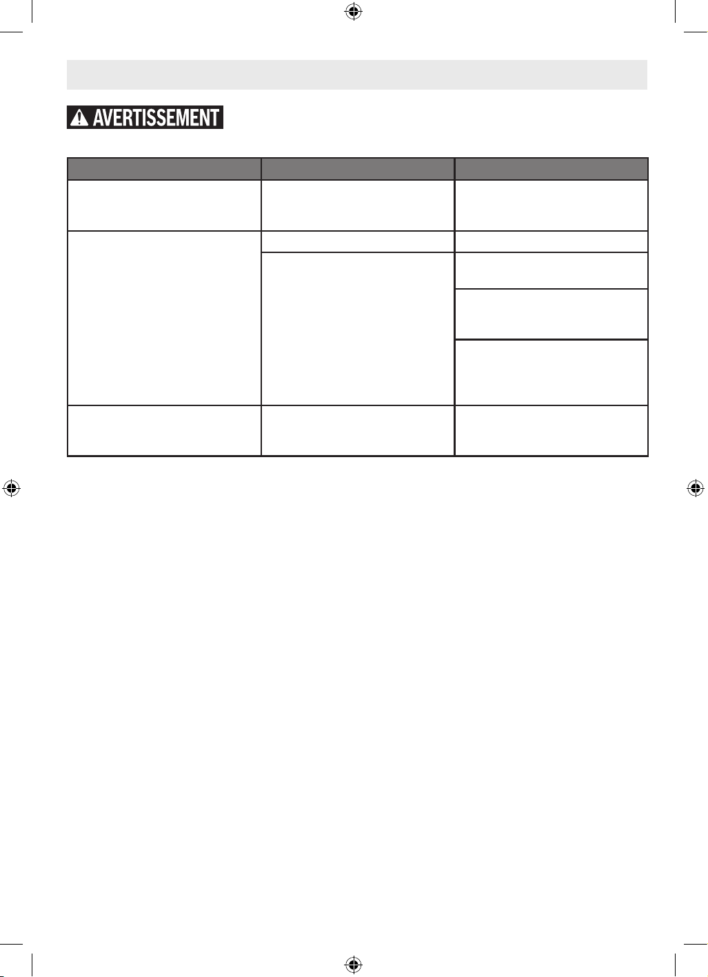
43
Recherche de la cause des problèmes
Débranchez la fiche de la prise de courant avant de procéder à des réglages ou des
changements d’accessoires, ou avant de ranger des outils électriques. De telles mesures
de sécurité préventives réduisent le risque de déclenchement accidentel de l’outil électrique.
Problème Cause Action corrective
L’ébouteuse est difficile à contrôler. Sens de l’avancement incorrect.
Inversez le sens de l’avancement. Voir
la section intitulée « Alimentation de
l’affleureuse portative » à la page 37.
L'ébouteuse pour coupe de finition
fonctionne lentement ; les coupes
sont grossières et les performances de
coupe sont médiocres.
Fraise émoussée ou endommagée. Remplacez la fraise.
L’ébouteuse est surchargée.
Reculez la pièce à travailler pour
réduire la charge.
Alimentation trop rapide ; ajustez la
vitesse d’alimentation ou le réglage de
la vitesse de l’affleureuse portative.
Coupe de trop grande envergure
pour une seule passe. Effectuez
plusieurs coupes progressivement plus
profondes.
Brûlures par friction sur la pièce à
travailler.
Avancement trop lent.
Ajustez la vitesse d’alimentation ou le
paramètre de réglage de la vitesse de
l’affleureuse portative.
16099221WG GLF55-25 OSI Final 20250228.indd 4316099221WG GLF55-25 OSI Final 20250228.indd 43 2/28/2025 8:49:31 AM2/28/2025 8:49:31 AM
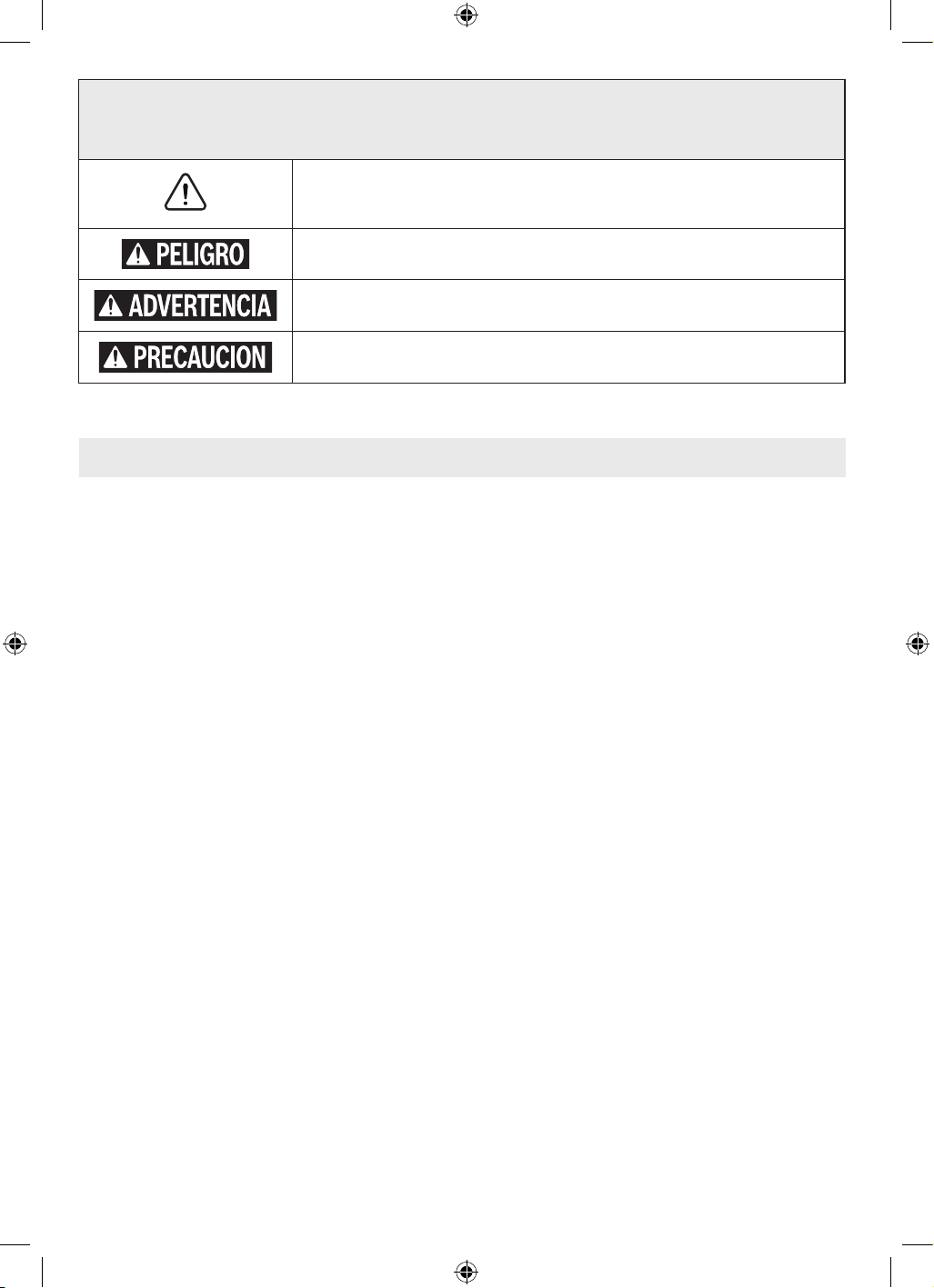
44
Tabla de contenido
Símbolos de seguridad
Las definiciones que aparecen a continuación describen el nivel de gravedad de cada palabra de aviso.
Por favor, lea el manual y preste atención a estos símbolos.
Este es el símbolo de alerta de seguridad. Se utiliza para alertarle a usted de posibles
peligros de lesiones corporales. Obedezca todos los mensajes de seguridad que sigan a
este símbolo para evitar posibles lesiones o la muerte.
PELIGRO indica una situación peligrosa que, si no se evita, causará la muerte o lesiones
graves.
ADVERTENCIA indica una situación peligrosa que, si no se evita, podría causar la muerte
o lesiones graves.
PRECAUCIÓN indica una situación peligrosa que, si no se evita, podría causar lesiones
leves o moderadas.
Advertencias generales de seguridad para
herramientas eléctricas ........................45
Instrucciones de seguridad para fresadoras............46
Advertencias de seguridad adicionales................47
Eliminación ..................................48
Uso previsto......................................48
Símbolos ........................................49
Especificaciones..................................50
Familiarización con su fresadora recortadora
GLF55-25 ...................................51
Ensamblaje y ajustes...............................53
Brocas de fresadora ...........................53
Reemplazo del portaherramienta.................54
Instalación la fresadora recortadora en la base fija
y desinstalación de la misma.................54
Instalación de la cubierta de extracción de polvo
(GLF001) (accesorio opcional) ..............55
Instalación de la guía de plantilla (accesorio
opcional) ................................55
Ensamblaje de la guía de borde recto (accesorio
opcional) ................................56
Instalación de la guía de borde recto (accesorio
opcional) ................................56
Instalación de la guía de rodillo/buje (PR003)
(accesorio opcional) .......................56
Funcionamiento de la herramienta ...................57
Ajuste de la profundidad de corte ................57
Utilización de la fresadora de trima ...............57
Utilización la base fija ..........................59
Utilización de la guía de borde recto (accesorio
opcional) ................................59
Utilización de la guía de plantilla (accesorio
opcional) ................................60
Utilización de brocas autopilotadas (vendido por
separado)................................60
Utilización de la guía de rodillo/buje (PR003)
(optional accessory) .......................61
Mantenimiento ...................................62
Mantenimiento general .........................62
Servicio de ajustes y reparaciones................62
Lubricacion de las herramientas .................62
Escobillas de carbón ...........................62
Rodamientos .................................62
Limpieza ....................................62
Almacenamiento y mantenimiento................62
Cordones de extensión.............................63
Accesorios.......................................63
Resolución de problemas...........................64
16099221WG GLF55-25 OSI Final 20250228.indd 4416099221WG GLF55-25 OSI Final 20250228.indd 44 2/28/2025 8:49:32 AM2/28/2025 8:49:32 AM

45
Advertencias generales de seguridad para herramientas eléctricas
Lea todas las advertencias de seguridad, instrucciones, ilustraciones y especificaciones
suministradas con esta herramienta eléctrica. Si no se siguen todas las instrucciones que se
indican a continuación, es posible que el resultado sea descargas eléctricas, incendio y/o lesiones graves.
GUARDE TODAS LAS ADVERTENCIAS E INSTRUCCIONES PARA REFERENCIA FUTURA.
La expresión “herramienta eléctrica” que se incluye en las advertencias se refiere a su herramienta eléctrica alimentada por la
red eléctrica (alámbrica) o su herramienta eléctrica alimentada por baterías (inalámbrica).
1. Seguridad en el área de trabajo
a. Mantenga el área de trabajo limpia y bien iluminada.
Las áreas desordenadas u oscuras invitan a que se
produzcan accidentes.
b. No utilice herramientas eléctricas en atmósferas
explosivas, tales como las existentes en presencia de
líquidos, gases o polvos inflamables. Las herramientas
eléctricas generan chispas, las cuales es posible que
incendien los polvos o los vapores.
c. Mantenga alejados a los niños y a los curiosos
mientras esté utilizando una herramienta eléctrica.
Las distracciones pueden hacerle perder el control de la
herramienta.
2. Seguridad eléctrica
a. Los enchufes de las herramientas eléctricas deben
coincidir con el tomacorriente. No modifique nunca
el enchufe de ninguna manera. No utilice enchufes
adaptadores con herramientas eléctricas conectadas
a tierra (puestas a masa). Los enchufes sin modificar
y los tomacorrientes coincidentes reducirán el riesgo de
descargas eléctricas.
b. Evite el contacto del cuerpo con superficies
conectadas a tierra o puestas a masa, tales
como tuberías, radiadores, estufas de cocina y
refrigeradores. Hay un mayor riesgo de descargas
eléctricas si el cuerpo del operador está conectado a
tierra o puesto a masa.
c. No exponga las herramientas eléctricas a la lluvia
ni a condiciones mojadas. La entrada de agua en una
herramienta eléctrica aumentará el riesgo de descargas
eléctricas.
d. No maltrate el cable. No use nunca el cable para
transportar, jalar o desenchufar la herramienta
eléctrica. Mantenga el cable alejado del calor, el
aceite, los bordes afilados o las piezas móviles. Los
cables dañados o enredados aumentan el riesgo de
descargas eléctricas.
e. Cuando utilice una herramienta eléctrica a la
intemperie, utilice un cable de extensión adecuado
para uso a la intemperie. La utilización de un cable
adecuado para uso a la intemperie reduce el riesgo de
descargas eléctricas.
f. Si es inevitable utilizar una herramienta eléctrica en
un lugar húmedo, utilice una fuente de alimentación
protegida por un interruptor de circuito accionado
por corriente de pérdida a tierra (GFCI, por sus
siglas en inglés). El uso de un GFCI reduce el riesgo de
descargas eléctricas.
3. Seguridad personal
a. Manténgase alerta, fíjese en lo que está haciendo y
use el sentido común cuando utilice una herramienta
eléctrica. No utilice una herramienta eléctrica
mientras esté cansado o bajo la influencia de
drogas, alcohol o medicamentos. Es posible que un
momento de desatención mientras se estén utilizando
herramientas eléctricas cause lesiones corporales
graves.
b. Utilice equipo de protección personal. Use siempre
protección ocular. Los equipos protectores, tales
como una máscara antipolvo, calzado de seguridad
antideslizante, casco o protección de la audición,
utilizados según lo requieran las condiciones, reducirán
las lesiones corporals.
c. Prevenga los arranques accidentales. Asegúrese de
que el interruptor esté en la posición de apagado
antes de conectar la herramienta eléctrica a la
fuente de alimentación y/o al paquete de batería,
levantar la herramienta eléctrica o transportarla. Si
se transportan herramientas eléctricas con el dedo en
el interruptor o si se suministra corriente a herramientas
eléctricas que tengan el interruptor en la posición de
encendido se invita a que se produzcan accidents.
d. Retire todas las llaves de ajuste o de tuerca antes
de encender la herramienta eléctrica. Es posible que
una llave de tuerca o de ajuste que se deje sujeta a una
pieza rotativa de la herramienta eléctrica cause lesiones
corporales.
e. No intente alcanzar demasiado lejos. Mantenga
un apoyo de los pies y un equilibrio adecuados en
todo momento. Esto permite un mejor control de la
herramienta eléctrica en situaciones inesperadas.
CONSERVE ESTAS INSTRUCCIONES
16099221WG GLF55-25 OSI Final 20250228.indd 4516099221WG GLF55-25 OSI Final 20250228.indd 45 2/28/2025 8:49:32 AM2/28/2025 8:49:32 AM

46
Advertencias generales de seguridad para herramientas eléctricas
CONSERVE ESTAS INSTRUCCIONES
f. Vístase adecuadamente. No se ponga ropa holgada
ni joyas. Mantenga el pelo y la ropa alejados de las
piezas móviles. La ropa holgada, las joyas o el pelo largo
pueden quedar atrapados en las piezas móviles.
g. Si se proporcionan dispositivos para la conexión de
instalaciones de extracción y recolección de polvo,
asegúrese de que estas estén conectadas y se utilicen
correctamente. El uso de recolección de polvo puede
reducir los peligros relacionados con el polvo.
h. No deje que la familiaridad obtenida con el uso
frecuente de las herramientas le haga volverse
complaciente e ignorar los principios de seguridad de
las herramientas. Una acción descuidada puede causar
lesiones graves en una fracción de Segundo.
4. Uso y cuidado de la herramienta eléctrica
a. No fuerce la herramienta eléctrica. Utilice la
herramienta eléctrica correcta para la aplicación
que vaya a realizar. La herramienta eléctrica correcta
hará el trabajo mejor y con más seguridad a la capacidad
nominal para la que fue diseñada.
b. No utilice la herramienta eléctrica si el interruptor no
la enciende y apaga. Cualquier herramienta eléctrica
que no se pueda controlar con el interruptor es peligrosa
y debe ser reparada.
c. Desconecte el enchufe de la fuente de alimentación
y/o retire el paquete de batería de la herramienta
eléctrica, si es retirable, antes de hacer cualquier
ajuste, cambiar accesorios o almacenar herramientas
eléctricas. Dichas medidas preventivas de seguridad
reducen el riesgo de arrancar accidentalmente la
herramienta eléctrica.
d. Guarde las herramientas eléctricas que no esté
usando fuera del alcance de los niños y no deje que
las personas que no estén familiarizadas con la
herramienta eléctrica o estas instrucciones utilicen la
herramienta eléctrica. Las herramientas eléctricas son
peligrosas en las manos de los usuarios no capacitados.
e. Realice mantenimiento de las herramientas
eléctricas y los accesorios. Compruebe si hay
desalineación o atoramiento de las piezas móviles,
rotura de piezas y cualquier otra situación que
pueda afectar al funcionamiento de la herramienta
eléctrica. Si la herramienta eléctrica está dañada,
haga que la reparen antes de utilizarla. Muchos
accidentes son causados por herramientas eléctricas
que reciben un mantenimiento deficiente.
f. Mantenga las herramientas de corte afiladas y
limpias. Las herramientas de corte mantenidas
adecuadamente, con bordes de corte afilados, tienen
menos probabilidades de atorarse y son más fáciles de
controlar.
g. Utilice la herramienta eléctrica, los accesorios y las
brocas de la herramienta, etc., de acuerdo con estas
instrucciones, teniendo en cuenta las condiciones de
trabajo y el trabajo que se vaya a realizar. El uso de la
herramienta eléctrica para operaciones distintas a las
previstas podría causar una situación peligrosa.
h. Mantenga los mangos y las superficies de agarre
secos, limpios y libres de aceite y grasa. Los mangos
resbalosos y las superficies de agarre resbalosas
no permiten un manejo y un control seguros de la
herramienta en situaciones inesperadas.
5. Servicio de ajustes y reparaciones
a. Haga que su herramienta eléctrica reciba servicio
de ajustes y reparaciones por un técnico de
reparaciones calificado que utilice únicamente
piezas de repuesto idénticas. Esto garantizará que se
mantenga la seguridad de la herramienta eléctrica.
Instrucciones de seguridad para fresadoras
Agarre la herramienta eléctrica solo por las superficies de
agarre con aislamiento, porque es posible que el cortador
entre en contacto con su propio cable. Es posible que cortar
un cable que tenga corriente haga que las partes metálicas
de la herramienta eléctrica que estén al descubierto tengan
corriente, lo cual podría causar una descarga eléctrica al
operador.
Utilice abrazaderas u otra manera práctica de soportar la
pieza de trabajo y sujetarla a una plataforma estable. Si la
pieza de trabajo se sujeta con la mano o contra el cuerpo, eso
deja inestable a dicho pieza y es posible que cause pérdida
de control.
16099221WG GLF55-25 OSI Final 20250228.indd 4616099221WG GLF55-25 OSI Final 20250228.indd 46 2/28/2025 8:49:32 AM2/28/2025 8:49:32 AM
47
CONSERVE ESTAS INSTRUCCIONES
Advertencias de seguridad adicionales
Si el corte en paredes existentes u otras áreas ciegas
donde puedan existir cables eléctricos es inevitable,
desconecte todos los fusibles o cortacircuitos que
alimentan el lugar de trabajo.
Asegúrese siempre de que la superficie de trabajo no
tenga clavos ni otros objetos extraños. El corte de un clavo
puede hacer que la broca y la herramienta salten y que la
broca se dañe.
Nunca tenga la pieza de trabajo en una mano y la
herramienta en la otra al utilizarla.
Nunca ponga las manos cerca o debajo de la superficie de
corte. Es más seguro fijar con abrazaderas el material y guiar
la herramienta con ambas manos.
Nunca ponga la pieza de trabajo sobre superficies duras,
tales como hormigón, piedra, etc. La broca de corte que
sobresale podrá hacer que la herramienta salte.
Use siempre gafas de seguridad y máscara antipolvo.
Use la herramienta únicamente en un área bien ventilada. La
utilización de dispositivos de seguridad personal y el trabajar
en un entorno seguro reducen el riesgo de que se produzcan
lesiones.
Después de cambiar las brocas o de hacer ajustes,
asegúrese de que la tuerca del portaherramienta y otros
dispositivos de ajuste estén apretados firmemente.
Un dispositivo de ajuste flojo puede desplazarse
inesperadamente, causando pérdida de control, y los
componentes giratorios flojos saldrán despedidos
violentamente.
Nunca arranque la herramienta cuando la broca esté
acoplada en el material. El borde de corte de la broca puede
engancharse en el material, causando pérdida de control de
la cortadora.
El sentido de avance de la broca en el material es muy
importante y está relacionado con el sentido de giro de la
broca. Al mirar a la herramienta desde arriba, la broca gira en
el sentido de las agujas del reloj. El sentido de avance de corte
debe ser en contra de las agujas del reloj.
NOTA: Los cortes interiores y exteriores requerirán un
sentido de avance distinto; consulte la sección sobre
avance de la fresadora. El hacer avanzar la herramienta
en sentido incorrecto hace que el borde de corte de
la broca se salga de la pieza de trabajo y tire de la her-
ramienta en el sentido de este avance.
Nunca use brocas desafiladas o dañadas. Las brocas
afiladas se deben manejar con cuidado. Las brocas
dañadas pueden romperse bruscamente durante el uso. Las
brocas desafiladas requieren más fuerza para empujar la
herramienta, con lo que es posible que la broca se rompa.
Nunca toque la broca durante ni inmediatamente después
de la utilización. Después del uso, la broca está demasiado
caliente como para tocarla con las manos desnudas.
Nunca deje la herramienta hasta que el motor se haya
detenido por completo. La broca que gira puede engancharse
en la superficie y tirar de la herramienta haciendo que usted
pierda el control.
No utilice un diámetro de cortador superior a
1-1/8 pulgadas. Es posible que la utilización de un cortador
de más de 1-1/8 pulgadas cause lesiones corporales.
Utilice únicamente brocas de fresadora que
tengan diámetros de vástago que coincidan con el
portaherramienta instalado. La utilización de una broca de
fresadora que tenga un vástago más pequeño podría hacer
que la broca se suelte durante su utilización y se convierta en
un proyectil.
No utilice nunca brocas de fresadora a velocidades que
sean más altas que su velocidad nominal máxima. Las
brocas de fresadora que giren a una velocidad mayor que su
velocidad nominal se pueden romper y salir despedidas.
Un GFCI y los dispositivos de protección personal, como
guantes de goma y calzado de goma de electricista,
mejorarán más su seguridad personal.
Mantenga los mangos secos, limpios y libres de aceite y
grasa. Las manos resbalosas no pueden controlar de modo
seguro la herramienta mecánica.
Desarrolle un programa de mantenimiento periódico de
la herramienta. Cuando limpie una herramienta, tenga
cuidado de no desmontar ninguna de sus partes, ya que
los cables internos podrían reubicarse incorrectamente
o pellizcarse, o los resortes de retorno de los protectores
de seguridad podrían montarse incorrectamente. Ciertos
agentes de limpieza, tales como gasolina, tetracloruro de
carbono, amoníaco, etc., podrían dañar las piezas de plástico.
Cierto polvo generado por
las operaciones de lijado,
aserrado, amolado y taladrado con herramientas
eléctricas, así como por otras actividades de construcción,
contiene sustancias químicas que se sabe que causan
cáncer, defectos de nacimiento u otros daños sobre la
reproducción. Algunos ejemplos de estas sustancias
químicas son:
• Plomo procedente de pinturas a base de plomo,
• Sílice cristalina procedente de ladrillos y cemento y otros
productos de mampostería, y
• Arsénico y cromo procedentes de madera de
construcción tratada químicamente.
16099221WG GLF55-25 OSI Final 20250228.indd 4716099221WG GLF55-25 OSI Final 20250228.indd 47 2/28/2025 8:49:32 AM2/28/2025 8:49:32 AM
48
CONSERVE ESTAS INSTRUCCIONES
El riesgo para usted por causa de estas exposiciones
varía, dependiendo de qué tan a menudo realice este tipo
de trabajo. Para reducir su exposición a estas sustancias
químicas: trabaje en un área bien ventilada y trabaje con
equipo de seguridad aprobado, tal como máscaras antipolvo
que estén diseñadas especialmente para impedir mediante
filtración el paso de partículas microscópicas.
Eliminación
Esta sección es parte del compromiso de Robert Bosch
Tool Corporation de preservar nuestro medio ambiente y
conservar nuestros recursos naturales.
Eliminación de herramientas
¡No deseche las herramientas eléctricas y las baterías/
baterías recargables en la basura doméstica!
Advertencias de seguridad adicionales
Utilice esta fresadora de trima solo tal como está previsto. Es posible que un uso no previsto
cause lesiones corporales o daños materiales.
Esta fresadora recortadora está diseñada para recortar
bordes, conformar bordes y fresar plantillas, así como
para fresar surcos, bordes, perfiles y agujeros alargados
en madera, plástico y panel de yeso, utilizando brocas de
fresadora con un vástago de 1/4 de pulgada (6,35 mm) que
tengan un diámetro de hasta 1 1/8 pulgadas (28,6 mm).
Esta fresadora recortadora no está diseñada para fresar en
metales. Esta fresadora recortadora no está diseñada para
utilizarse en una mesa de fresadora.
Uso previsto
16099221WG GLF55-25 OSI Final 20250228.indd 4816099221WG GLF55-25 OSI Final 20250228.indd 48 2/28/2025 8:49:32 AM2/28/2025 8:49:32 AM
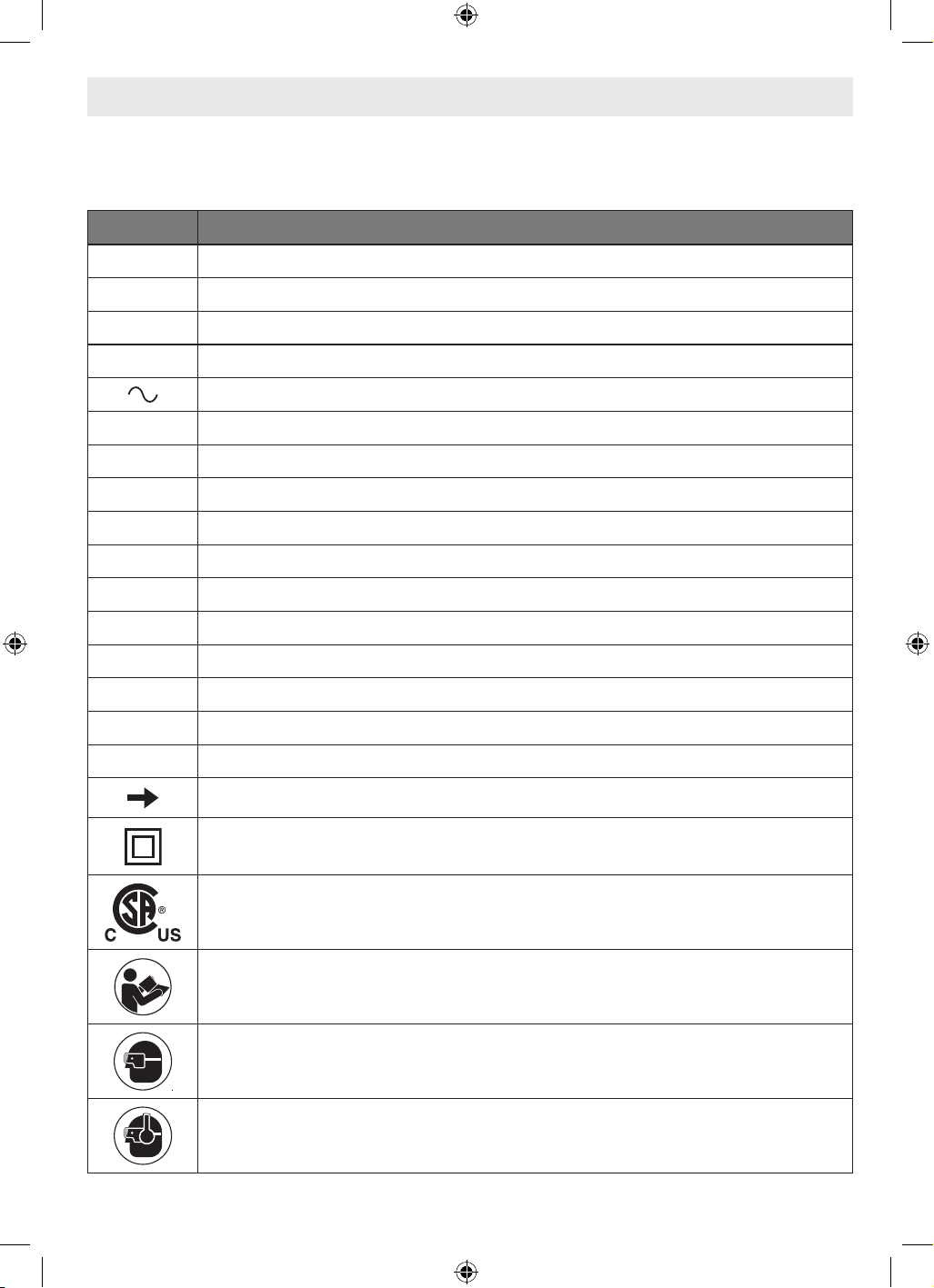
49
Símbolos
Importante: Es posible que se utilicen algunos de los siguientes símbolos en esta herramienta. Por favor, estúdielos y
aprenda su significado. La interpretación correcta de estos símbolos le permitirá utilizar la herramienta mejor y de manera
más segura.
Símbolo Designation/Explanation
V Voltios (tensión)
A Amperios (corriente)
Hz Hercios (frecuencia)
W Watt (potencia)
Corriente alterna (tipo o característica de corriente)
lb Libras (peso)
kg Kilogramos (peso)
ft Pies (longitud)
in Pulgadas (longitud)
m Metro (longitud)
cm Centímetro (longitud)
mm Milímetros (longitud)
F Fahrenheit (temperatura)
C Celsius (temperatura)
n0 Velocidad sin carga (velocidad rotacional sin carga)
RPM Revoluciones o alternación por minuto (velocidad)
Flecha (acción en el sentido de la flecha)
Construcción de Clase II (designa herramientas de construcción con aislamiento doble)
Este símbolo indica que esta herramienta está homologada por la Canadian Standards Association,
conforme a las normas estadounidenses y canadienses.
Alerta al usuario para que lea el manual.
Alerta al usuario para que use protección de los ojos.
Alerta al usuario para que use protección de la audición.
16099221WG GLF55-25 OSI Final 20250228.indd 4916099221WG GLF55-25 OSI Final 20250228.indd 49 2/28/2025 8:49:32 AM2/28/2025 8:49:32 AM
50
Especificaciones
Número de modelo GLF55-25
Corriente nominal 4.3 A
Velocidad sin carga 33,000 RPM
Tamaño de broca máx. 1-1/8 pulgadas
Tamaño del portaherramienta 1/4 pulgadas
Importante: Es posible que se utilicen algunos de los siguientes símbolos en esta herramienta. Por favor, estúdielos y
aprenda su significado. La interpretación correcta de estos símbolos le permitirá utilizar la herramienta mejor y de manera
más segura.
Símbolo Designation/Explanation
Alerta al usuario para que use protección respiratoria.
Alerta al usuario para que use protección de los ojos, respiratoria y de la audición.
Símbolos
16099221WG GLF55-25 OSI Final 20250228.indd 5016099221WG GLF55-25 OSI Final 20250228.indd 50 2/28/2025 8:49:32 AM2/28/2025 8:49:32 AM
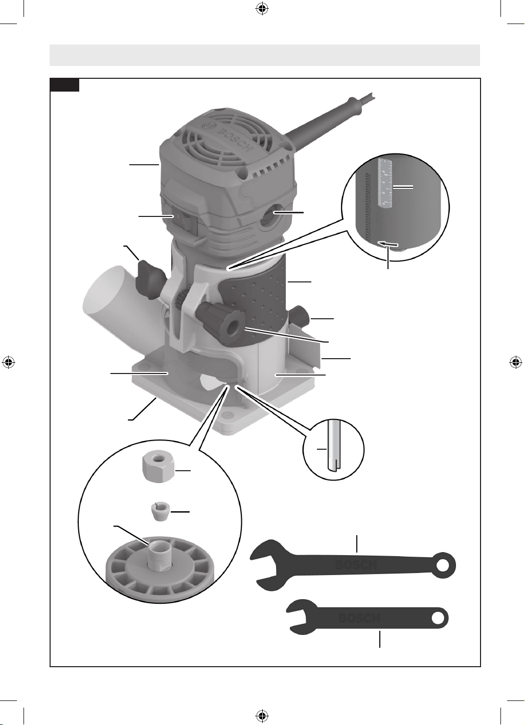
51
Familiarización con su fresadora recortadora GLF55-25
2
1
6
11
15
14
19
16
8
8
13
3
7
18
17
4
5
12
9
10
Fig. 1
16099221WG GLF55-25 OSI Final 20250228.indd 5116099221WG GLF55-25 OSI Final 20250228.indd 51 2/28/2025 8:49:32 AM2/28/2025 8:49:32 AM
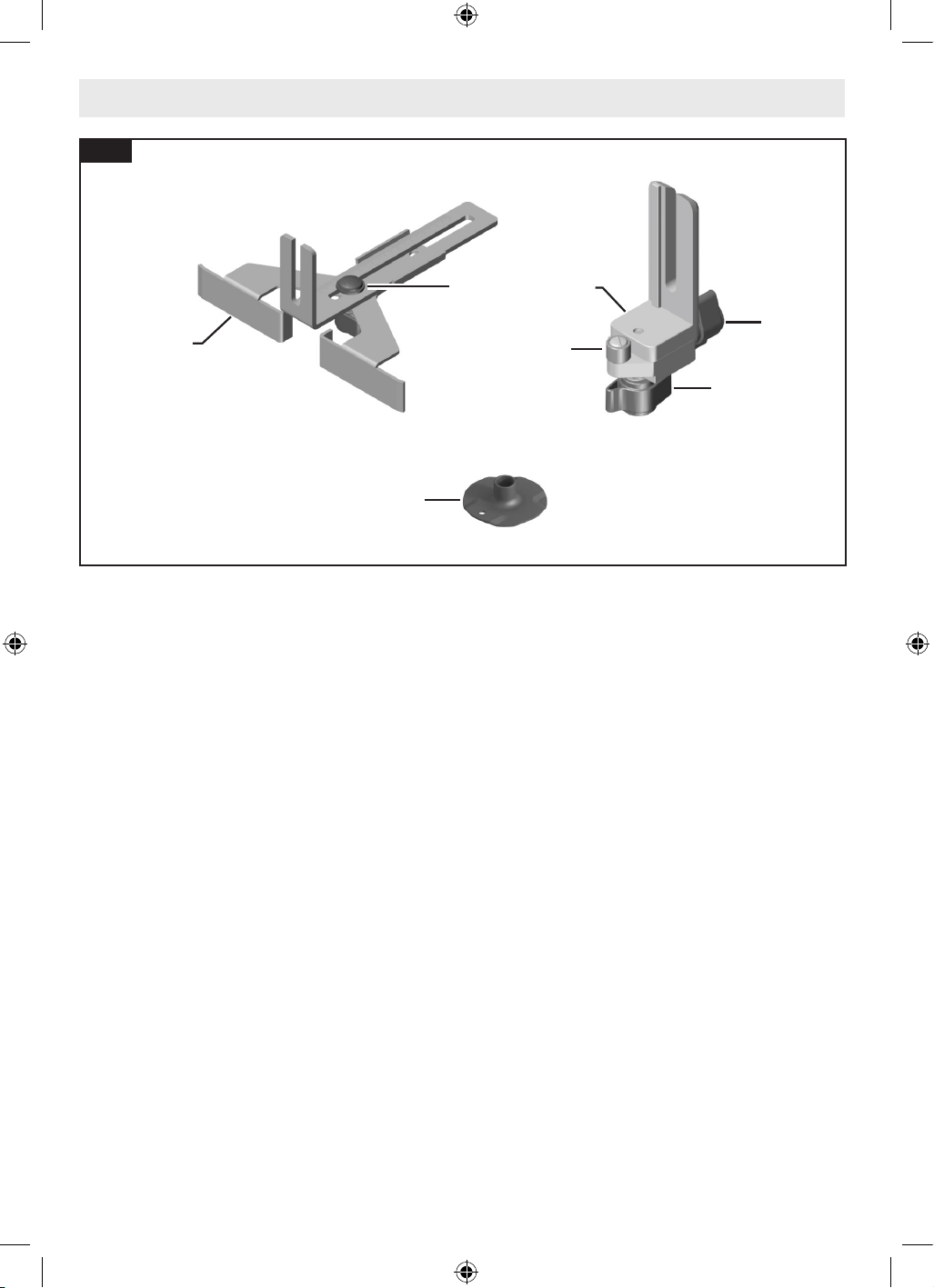
52
Familiarización con su fresadora recortadora GLF55-25
1 Interruptor de encendido y apagado
2 Fresadora recortadora
3 Empuñadura (zona de agarre aislada)
4 Tornillo de apriete manual del accesorio trasero
5 Protector antivirutas
6 Pomo de fijación
7 Perilla de ajuste de profundidad
8 Escala de profundidad
9 Broca de fresadora
10 Sentido de rotación
11 Subbase
12 Base fija
13 Soporte para escobillas de carbono
14 Portaherramienta
15 Tuerca del portaherramienta
16 Husillo
17 Llave de fijación del husillo (10 mm)
18 Llave para la tuerca del portaherramienta (17 mm)
19 Cubierta de extracción de polvo (GLF001)
20 Guía de plantilla
21 Guía de borde recto
22 Perno de mariposa para guía de borde recto
23 Guía de rodillo/buje para la base fija (PR003)
24 Tuerca de mariposa para la alineación horizontal de
la guía de rodillo/buje (en la parte inferior)
25 Tuerca de mariposa para la alineación horizontal de
la guía de rodillo/buje (en la parte trasera)
26 Rodillo/buje
* Vendido por separado.
20
22
24
21
23
25
26
Fig. 2
16099221WG GLF55-25 OSI Final 20250228.indd 5216099221WG GLF55-25 OSI Final 20250228.indd 52 2/28/2025 8:49:33 AM2/28/2025 8:49:33 AM
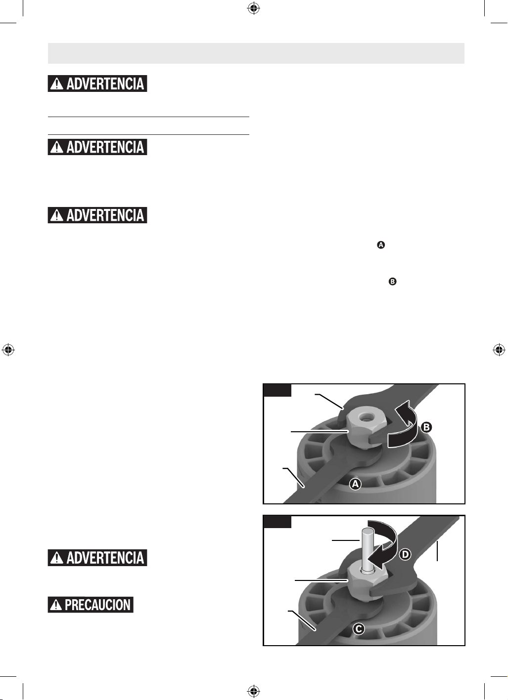
53
Ensamblaje y ajustes
Brocas de fresadora
Utilice únicamente brocas
de fresadora que tengan
diámetros de vástago que coincidan con el portaher-
ramienta instalado. La utilización de una broca de fresadora
que tenga un vástago más pequeño podría hacer que la broca
se suelte durante su utilización y se convierta en un proyectil.
No utilice nunca brocas de
fresadora a velocidades que
sean más altas que su velocidad nominal máxima. Las
brocas de fresadora que giren a una velocidad mayor que su
velocidad nominal se pueden romper y ser lanzadas al aire.
Selección de las brocas de fresadora
Esta herramienta está diseñada para realizar una amplia
variedad de aplicaciones de fresado que utilizan brocas con
un vástago de 1/4 de pulgada. Estas aplicaciones incluyen
trabajo de la madera, como por ejemplo conformado de
bordes, elaboración de surcos y realización de letreros.
Esta fresadora también es ideal para recortar materiales
laminados, materiales fenólicos y otros materiales que han
sido adheridos a un substrato de manera que sobresalen del
mismo típicamente alrededor de 1/8 de pulgada (3 mm). Hay
disponibles como accesorios un amplio surtido de brocas de
fresadora con diferentes perfiles. Utilice únicamente brocas
de buena calidad.
Nota: Aunque la broca de fresadora se puede instalar en
la fresadora de palma y desinstalar de la misma mientras
la fresadora esté instalada en una base, se recomienda
desinstalar la fresadora de palma de la base antes de instalar
una broca. Consulte la sección correspondiente para la base
seleccionada en uso sobre cómo separar la fresadora de
palma de la base.
Instalación/desinstalación de una broca de
fresadora
(Fig. 3, Fig. 4)
No utilice un diámetro de
cortador superior a 1-1/2
pulgadas. Es posible que la utilización de un cortador de más
de 1-1/2 pulgadas cause lesiones corporales.
No apriete el portaherra-mienta
sin tener una broca insertada. Es
posible que si se aprieta el portaherramienta sin tener una
broca insertada se causen daños a la herramienta.
Antes de insertar la broca de fresadora seleccionada 9,
asegúrese de que el husillo 16, el portaherramienta 14,
la tuerca del portaherramienta 15 y el vástago de la broca
estén limpios. El vástago de la broca debe estar recto, no
estar dañado y tener un tamaño adecuado en relación con el
portaherramienta 14.
1. Siga los pasos in “Instalación la fresadora recortadora
en la base fija y desinstalación de la misma” en la página
54 para retirar la fresadora recortadora 2 de la base
fija 12.
2. Utilizando la llave de fijación del husillo 17, sujete el
husillo 16 en una posición fija .
3. Utilice la llave para la tuerca del portaherramienta 18
para aflojar la tuerca del portaherramienta 15 en sentido
contrario al de las agujas del reloj .
4. Si es necesario, retire la broca de fresadora 9 instalada.
5. Inserte el vástago de la broca de fresadora 9 en el
portaherramienta 14 tanto como sea posible y luego
retroceda el vástago hasta que los cortadores estén
aproximadamente a una distancia de 1/8 a 1/4 de
pulgada de la cara de la tuerca del portaherramienta 15.
Desconecte el enchufe de la fuente de alimentación antes de hacer cualquier ajuste,
cambiar accesorios o almacenar herramientas eléctricas. Dichas medidas preventivas de
seguridad reducen el riesgo de arrancar accidentalmente la herramienta eléctrica.
15
18
17
Fig. 3
18
15
9
17
Fig. 4
16099221WG GLF55-25 OSI Final 20250228.indd 5316099221WG GLF55-25 OSI Final 20250228.indd 53 2/28/2025 8:49:33 AM2/28/2025 8:49:33 AM
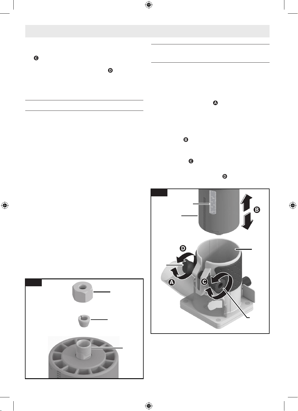
54
Ensamblaje y ajustes
6. Con la broca de fresadora 9 insertada y la llave de fijación
del husillo 17 sujetando el husillo 16 en una posición fija
, utilice la llave para la tuerca del portaherramienta 18
para apretar firmemente la tuerca del portaherramienta
15 en el sentido de las agujas del reloj .
Nota: Para garantizar un agarre adecuado de la broca de
fresadora 9 y minimizar la desviación, el vástago de la broca
de fresadora 9 se debe insertar al menos 5/8 de pulgada.
Reemplazo del portaherramienta
(Fig. 3, Fig. 4, Fig. 5)
Esta herramienta incluye un portaherramienta 14 de
1/4 de pulgada preinstalado, dentro de la tuerca del
portaherramienta 15, que se debe utilizar con un vástago de
accesorio de 1/4 de pulgada de diámetro.
Para reemplazar el ensamblaje del portaherramienta 14:
1. Retire la fresadora recortadora 2 de la base fija 12 tal
como se describe en “Instalación la fresadora recortadora
en la base fija y desinstalación de la misma” en la página
54 más adelante.
2. Utilizando la llave de fijación del husillo 17, sujete el
husillo 16 en posición fija.
3. Utilice la llave para la tuerca del portaherramienta 18
para aflojar la tuerca del portaherramienta 15 en sentido
contrario al de las agujas del reloj .
4. Desenrosque y retire el ensamblaje de la tuerca del
portaherramienta 15.
5. Asegúrese de que las roscas del husillo 16 estén
limpias y que el portaherramienta 14 esté colocado
adecuadamente en la tuerca del portaherramienta 15.
6. Utilizando la mano, enrosque el ensamblaje del
portaherramienta 14 nuevo en el husillo 16.
Instalación la fresadora recortadora en la
base fija y desinstalación de la misma
(Fig. 6)
Instalación de la fresadora recortadora en la
base fija
Afloje el mecanismo de sujeción ubicado en la base fija 12
girando la perilla de sujeción 6 en sentido contrario al de
las agujas del reloj.
1. Alinee tanto la fresadora recortadora 2 como la base fija
12 de manera que estén orientadas hacia delante.
2. Deslice la fresadora recortadora 2 hacia el interior de la
base fija 12 .
3. Gire la perilla de ajuste de profundidad 7 para alcanzar
con precisión la profundidad deseada en la escala de
profundidad 8 .
4. Apriete firmemente la perilla de sujeción 6 girándola en
el sentido de las agujas del reloj para fijar la fresadora
recortadora 2 en la posición correcta.
15
16
14
Fig. 5
6
7
12
2
8
Fig. 6
16099221WG GLF55-25 OSI Final 20250228.indd 5416099221WG GLF55-25 OSI Final 20250228.indd 54 2/28/2025 8:49:33 AM2/28/2025 8:49:33 AM
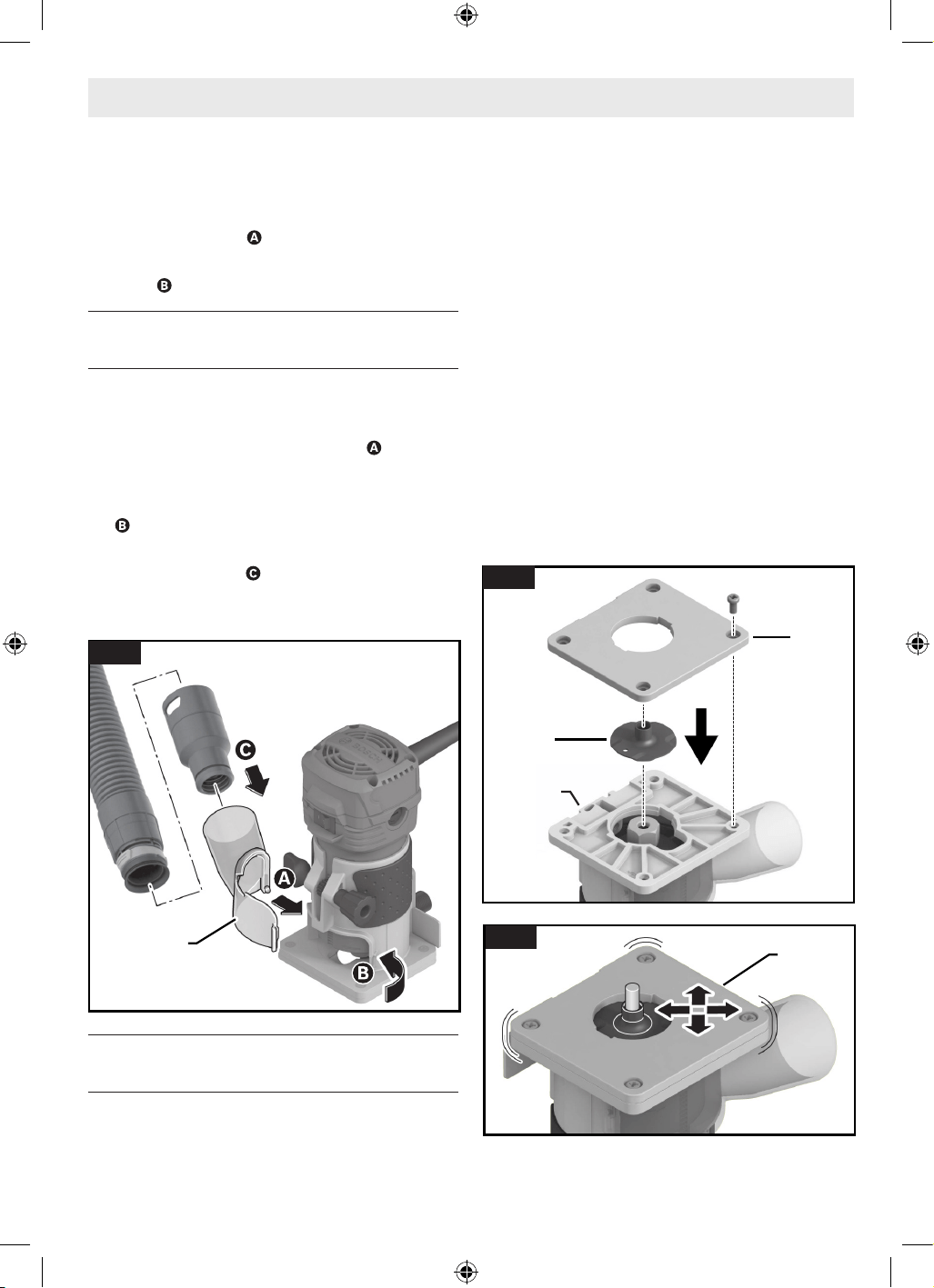
55
Ensamblaje y ajustes
Desinstalación de la fresadora recortadora de
la base fija
5. Afloje el mecanismo de sujeción ubicado en la base fija
12 girando la perilla de sujeción 6 en sentido contrario al
de las agujas del reloj .
6. Deslice la fresadora recortadora 2 hacia fuera de la base
fija 12 .
Instalación de la cubierta de extracción de
polvo (GLF001) (accesorio opcional)
(Fig. 7)
1. Coloque la lengüeta pequeña que se encuentra en la
parte inferior izquierda de la cubierta de extracción de
polvo 19 dentro de la ranura de la base y luego rote
la cubierta de extracción de polvo 19 hacia la base hasta
que la lengüeta ubicada en el lado derecho se ajuste a
presión en la ranura ubicada en el lado derecho de la base
; habrá un clic audible.
2. Conecte la cubierta a la aspiradora utilizando una boquilla
de ajuste por fricción .
Para retirar la cubierta de extracción de polvo 19, agarre el
lado del adaptador y jálelo hacia fuera.
Instalación de la guía de plantilla (accesorio
opcional)
(Fig. 8, Fig. 9)
1. Desenrosque los cuatro tornillos ubicados en la parte
inferior de la subbase 11 y retire la subbase 11.
2. Alinee la configuración de ranuras e inserte la guía de
plantilla 20 en la base fija 12.
3. Enrosque de manera floja la subbase 11 de vuelta sobre
la base fija 12. Asegúrese de que la subbase 11 aún se
pueda mover libremente.
4. Alinee la subbase 11 de manera que la guía de plantilla
20 esté centrada sobre la abertura ubicada en la subbase
11.
Nota: El dispositivo centrador RA1151 opcional se pu-
ede utilizar para centrar con precisión la guía de plantilla
o la subbase.
5. Sujete la subbase 11 en esta posición y apriete
firmemente los tornillos de sujeción.
6. Instale la broca de fresadora 9 deseada. Consulte
“Instalación/desinstalación de una broca de fresadora”
en la página 53.
Nota: La fresadora recortadora 2 debe permanecer instalada
en la base fija 12 cuando se instale una broca de fresadora 9
mientras se esté utilizando una guía de plantilla 20.
19
CLICK!
CLICK!
Fig. 7
11
20
12
Fig. 8
11
Fig. 9
16099221WG GLF55-25 OSI Final 20250228.indd 5516099221WG GLF55-25 OSI Final 20250228.indd 55 2/28/2025 8:49:33 AM2/28/2025 8:49:33 AM
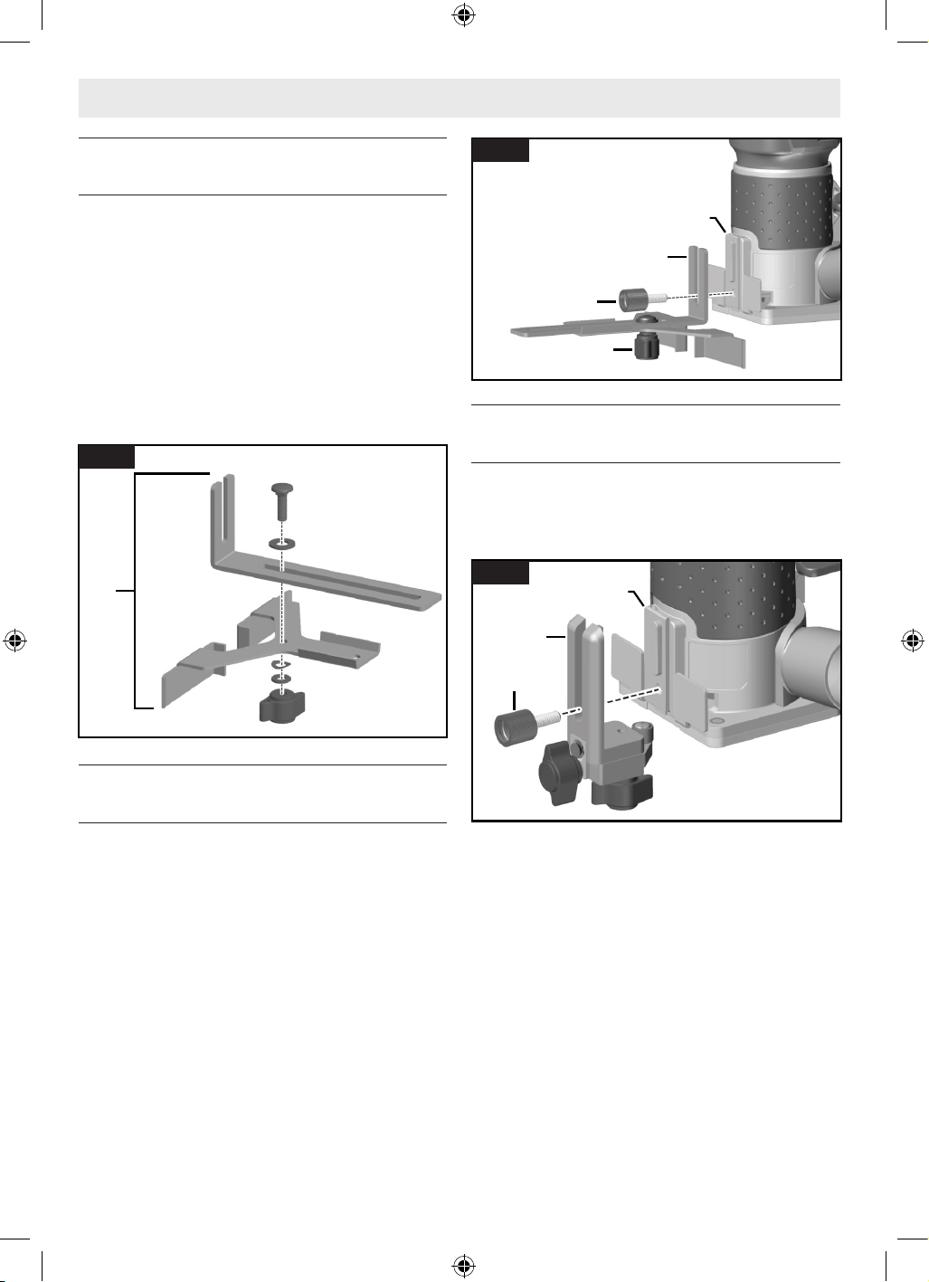
56
Ensamblaje de la guía de borde recto
(accesorio opcional)
(Fig. 10)
La guía de borde recto 21 es un accesorio opcional que guiará
la fresadora paralela a un borde recto.
La guía de borde recto 21 se suministra en dos partes que se
deberán sujetar juntas con un perno, una tuerca de mariposa
y arandelas.
Para ensamblar la guía de borde recto 21:
1. Posicione la placa de guía sobre la guía recta.
2. Fije juntas las dos partes con el perno, la tuerca de
mariposa y las arandelas.
Instalación de la guía de borde recto
(accesorio opcional)
(Fig. 11)
1. Instale la guía de borde recto 21 en la base fija 12
utilizando el tornillo de apriete manual del accesorio
trasero 4.
2. Utilice el perno de mariposa para la guía de borde recto
22 para ajustar la profundidad de tope requerida.
Instalación de la guía de rodillo/buje (PR003)
(accesorio opcional)
(Fig. 12)
1. Instale la guía de rodillo/buje 23 en la base fija 12
utilizando el tornillo de apriete manual del accesorio
trasero 4.
Ensamblaje y ajustes
21
Fig. 10
12
22
4
21
Fig. 11
12
4
23
Fig. 12
16099221WG GLF55-25 OSI Final 20250228.indd 5616099221WG GLF55-25 OSI Final 20250228.indd 56 2/28/2025 8:49:34 AM2/28/2025 8:49:34 AM
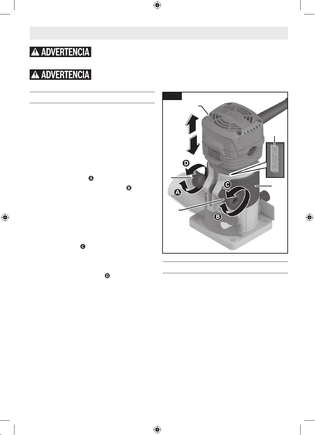
57
Funcionamiento de la herramienta
Ajuste de la profundidad de corte
(Fig. 13)
1. Instale la broca de fresadora 9 deseada. Consulte
“Instalación/desinstalación de una broca de fresadora”
en la página 53.
2. Instale la fresadora recortadora 2 en la base fija 12.
3. Coloque el ensamblaje de la fresadora/base sobre la
pieza de trabajo.
4. Afloje el mecanismo de sujeción ubicado en la base fija
12 girando la perilla de sujeción 6 en sentido contrario
al de las agujas del reloj .
5. Gire la perilla de ajuste de profundidad 7 para bajar
lentamente la fresadora hasta que la broca de fresadora
toque la pieza de trabajo.
6. Observe la lectura mostrada en la escala de profundidad
8 y añada la profundidad de corte deseada a este valor
para determinar el valor objetivo de la escala.
7. Levante el ensamblaje de la fresadora/base para
separarlo de la pieza de trabajo y gire la perilla de ajuste
de profundidad 7 para bajar o subir la fresadora
recortadora 2 dentro de la base hasta que se alcance el
valor objetivo de la escala.
8. Apriete firmemente la perilla de sujeción 6 girándola en
el sentido de las agujas del reloj para fijar la fresadora
recortadora 2 en la posición correcta.
9. Asegúrese de que la fresadora de trima 2 esté firmemente
sujeta en la base.
10. Haga un corte de prueba para verificar que la fresadora
de trima 2 esté ajustada a la profundidad deseada.
Cortes profundos
Para realizar cortes profundos, haga varios cortes
progresivamente más profundos comenzando a una
profundidad y haciendo luego varias pasadas subsiguientes,
aumentando la profundidad de corte con cada pasada. Para
estar seguro de que los ajustes de profundidad sean los que
se desean, puede que usted quiera hacer cortes de prueba en
material de desecho antes de comenzar el trabajo.
Utilización de la fresadora de trima
(Fig. 14)
Interruptor de encendido y apagado
La herramienta se puede ENCENDER o APAGAR por medio del
interruptor de encendido y apagado 1 ubicado en la carcasa
del motor. Un lado del interruptor está marcado con la letra “I”
para “ENCENDIDO“ y el otro lado del interruptor está marcado
con la letra “O” para “APAGADO“.
PARA ENCENDER LA HERRAMIENTA: Deslice el interruptor 1
hacia la izquierda y se revelará la marca “I”.
PARA APAGAR LA HERRAMIENTA: Deslice el interruptor 1
hacia la derecha, y se revelará la marca “O”.
Desconecte el enchufe de la fuente de alimentación antes de hacer cualquier ajuste,
cambiar accesorios o almacenar herramientas eléctricas. Dichas medidas preventivas de
seguridad reducen el riesgo de arrancar accidentalmente la herramienta eléctrica.
Utilice equipo de protección personal. Use siempre protección ocular. Los equipos protectores,
tales como una máscara antipolvo, calzado de seguridad antideslizante, casco o protección de la
audición, utilizados según lo requieran las condiciones, reducirán las lesiones corporals.
6
7
12
2
8
Fig. 13
16099221WG GLF55-25 OSI Final 20250228.indd 5716099221WG GLF55-25 OSI Final 20250228.indd 57 2/28/2025 8:49:34 AM2/28/2025 8:49:34 AM
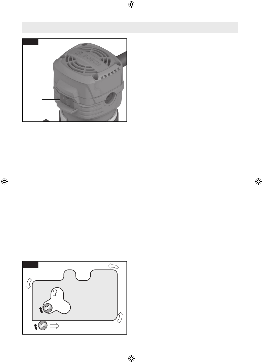
58
Funcionamiento de la herramienta
Protección contra rearranques
Para encender la fresadora, su interruptor se debe cambiar
de la posición de APAGADO a la de ENCENDIDO mientras está
enchufada en la fuente de alimentación.
La protección contra rearranques ayuda a prevenir los
arranques accidentales después de que se haya interrumpido
la alimentación eléctrica, p. ej., si se desenchufó la
herramienta con el interruptor bloqueado en la posición
de ENCENDIDO. Para reanudar el funcionamiento, ponga
el interruptor de encendido y apagado 1 en la posición de
APAGADO y luego rearranque la herramienta.
Avance de la fresadora de trima
(Fig. 15)
Esta sección explica conceptos de sobre cómo hacer avanzar
adecuadamente la fresadora de trima mientras está en
funcionamiento.
Asegúrese de leer las secciones correspondientes para
obtener pasos operativos detallados para cada tipo de base.
Tal como se ve desde la parte superior de la fresadora de
trima, la broca gira en el sentido de las agujas del reloj y los
bordes de corte de la broca están posicionados para cortar de
la mejor manera posible en la pieza de trabajo. Por lo tanto, el
corte más eficiente se realiza haciendo avanzar la fresadora
de trima de manera que la broca gire hacia la pieza de trabajo,
no alejándose de ella. La siguiente figura muestra el avance
adecuado para diversos cortes. Qué tan rápido se haga
avanzar la fresadora depende de la dureza del material y el
tamaño del corte. Para algunos materiales, lo mejor es hacer
varios cortes de profundidad creciente.
Si la fresadora de trima es difícil de controlar, se calienta,
funciona muy lentamente o deja un corte imperfecto,
considere estas causas:
• Sentido de avance incorrecto: difícil de controlar.
• Avance incorrecto: sobrecarga el motor.
• Broca desafilada: sobrecarga el motor.
• El corte es demasiado grande para una pasada:
sobrecarga el motor.
• Avance demasiado lento: deja quemaduras de fricción en
la pieza de trabajo.
Avance de manera suave y firme (no fuerce).
La práctica y la experiencia le ayudarán a familiarizarse con
cómo suena y se siente la fresadora de trima cuando está
funcionando óptimamente.
Guiado de la fresadora de trima
(Fig. 16)
La fresadora se puede guiar a través de la pieza de trabajo
de cualquiera de varias maneras. El método que usted utilice
depende, por supuesto, de las exigencias del trabajo en
particular y la conveniencia. Para operaciones de fresado
tales como elaboración de surcos o mortajas, a menudo
es necesario guiar la herramienta en una línea paralela a un
borde recto. Un método de obtener un corte recto es fijar
firmemente con abrazaderas una tabla u otro borde recto a
la superficie de trabajo y guiar el borde de la subbase de la
fresadora a lo largo de este camino.
Agarre siempre la fresadora recortadora separada de la pieza
de trabajo cuando ponga el interruptor en la posición de
ENCENDIDO o APAGADO. Contacte la pieza de trabajo con
la fresadora después de que la fresadora recortadora haya
alcanzado la velocidad máxima y retírela de la pieza de trabajo
antes de poner el interruptor en la posición de APAGADO.
La utilización de esta manera prolongará la vida útil del
interruptor y del motor y aumentará enormemente la calidad
del trabajo que usted realiza.
1
Fig. 14
Pieza de
trabajo
Sentido de avance de la
fresadora
Fig. 15
16099221WG GLF55-25 OSI Final 20250228.indd 5816099221WG GLF55-25 OSI Final 20250228.indd 58 2/28/2025 8:49:34 AM2/28/2025 8:49:34 AM
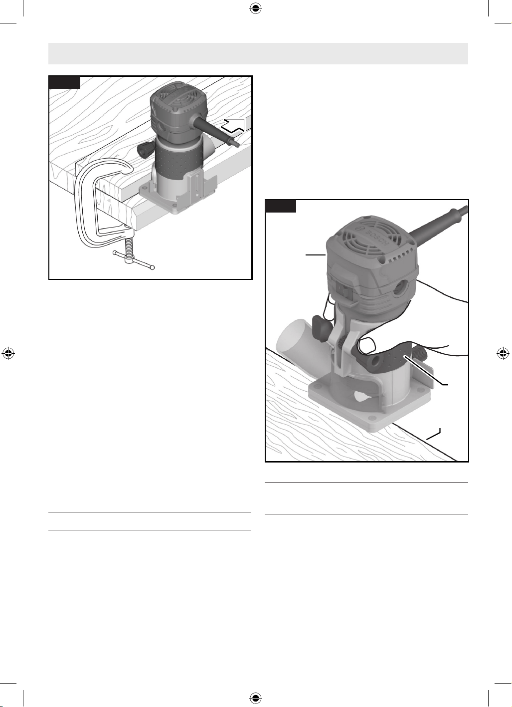
59
Funcionamiento de la herramienta
Velocidad de avance
Cuando frese o haga trabajo relacionado en madera
y plásticos, los mejores acabados se producirán si la
profundidad de corte y la velocidad de avance están reguladas
para mantener el motor funcionando a alta velocidad. Haga
avanzar la fresadora de trima a una velocidad moderada. Los
materiales blandos requieren una velocidad de avance más
rápida que los materiales duros. Es posible que la fresadora
se detenga si se utiliza incorrectamente o se sobrecarga.
Reduzca la velocidad de avance para prevenir posibles daños
a la herramienta. Asegúrese siempre de que la tuerca del
portaherramienta esté firmemente apretada antes de utilizar
la herramienta. Utilice siempre brocas de fresadora con la
longitud de corte más corta necesaria para producir el corte
deseado. Esto minimizará la desviación y la vibración de la
broca de fresadora. Es posible que sea necesario hacer el
corte en más de una pasada con ajustes progresivamente más
profundos para evitar sobrecargar el motor. Si la broca corta
libremente y el motor no pierde velocidad, generalmente la
profundidad de corte es correcta.
Utilización la base fija
(Fig. 17)
1. Instale la broca de fresadora 9. Consulte “Instalación/
desinstalación de una broca de fresadora” en la página
53.
2. Ajuste la profundidad de corte. Consulte “Ajuste de la
profundidad de corte” en la página 57.
3. Enchufe la fresadora recortadora 2 en la fuente de
alimentación.
4. Agarre firmemente la fresadora recortadora 2 por la
superficie de agarre con aislamiento 3.
1. Encienda la fresadora recortadora 2. Consulte
“Interruptor de encendido y apagado” en la página 57.
2. Avance la fresadora recortadora 2 para que penetre en la
pieza de trabajo. Consulte “Ajuste de la profundidad de
corte” en la página 57.
3. Una vez que se haya completado la operación de fresado,
apague la fresadora recortadora 2. Consulte “Interruptor
de encendido y apagado” en la página 57.
Utilización de la guía de borde recto
(accesorio opcional)
(Fig. 18)
La guía de borde recto 21 es un accesorio opcional que guiará
la fresadora de trima paralela a un borde recto.
La guía cuenta con una escala para posicionar con precisión la
guía de borde en relación con la broca. Con la guía instalada y
ajustada, la fresadora se deberá hacer avanzar normalmente,
manteniendo la guía en contacto con el borde de la pieza de
trabajo en todo momento.
La guía de fresadora también se puede posicionar directa-
mente debajo de la base de fresadora para operaciones en
las que se necesite un corte cerca del borde de la superficie
Fig. 16
2
3
Pieza de
Pieza de
trabajo
trabajo
Borde de
Borde de
la pieza de
la pieza de
trabajo
trabajo
Fig. 17
16099221WG GLF55-25 OSI Final 20250228.indd 5916099221WG GLF55-25 OSI Final 20250228.indd 59 2/28/2025 8:49:34 AM2/28/2025 8:49:34 AM
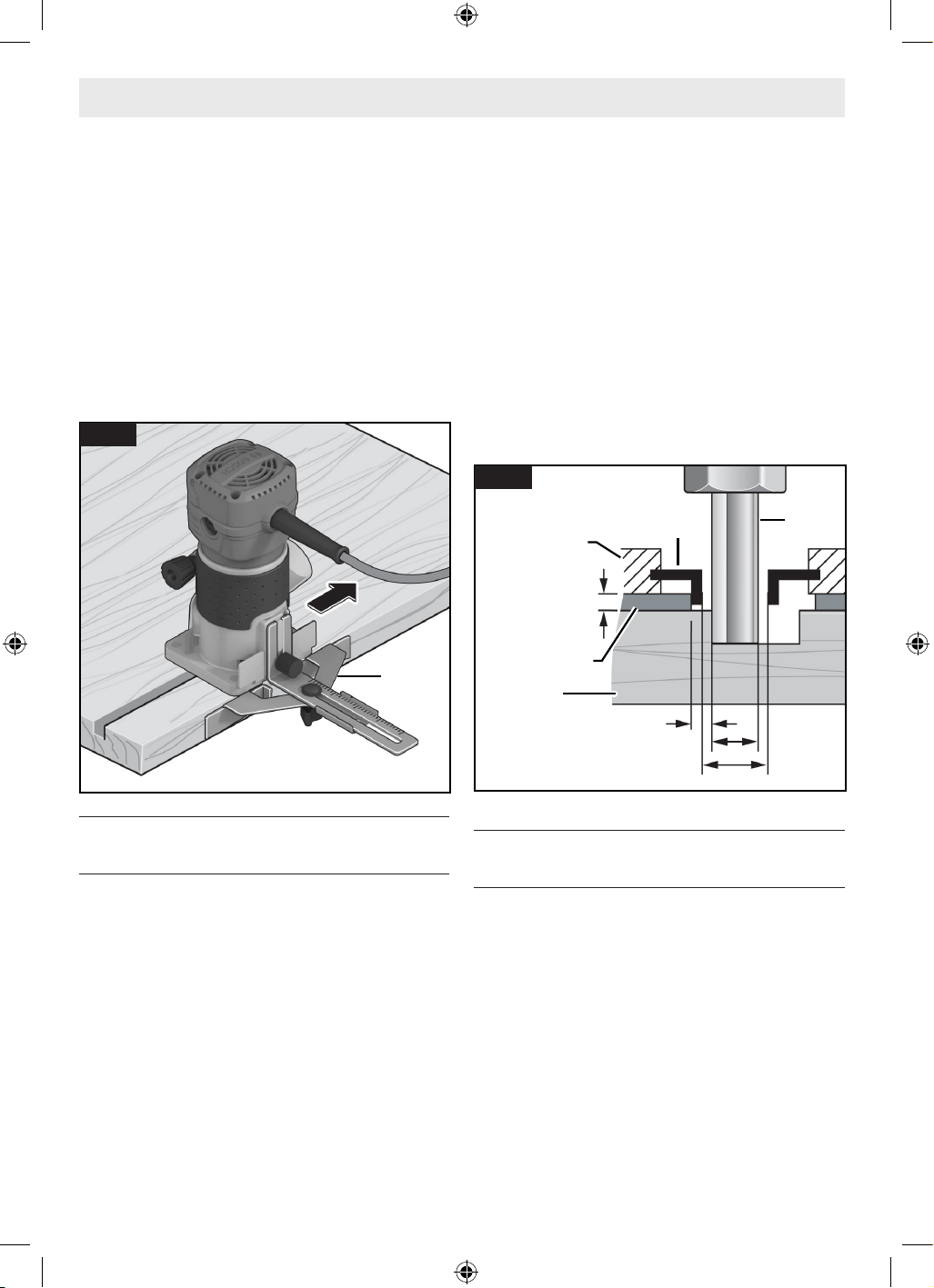
60
de trabajo o en dicho borde, por ejemplo, al redondear
tablones de cubierta. Para obtener instrucciones completas
de instalación y utilización, sírvase consultar las instrucciones
incluidas con este accesorio.
Para utilizar la guía de borde recto 21:
1. Siga los pasos de “Ensamblaje de la guía de borde recto
(accesorio opcional)” y “Instalación de la guía de borde
recto (accesorio opcional)” en la página 56 para
ensamblar e instalar la guía de borde recto 21.
2. Con la guía instalada y ajustada, la recortadora se deberá
hacer avanzar normalmente, manteniendo la guía en
contacto con el borde de la pieza de trabajo en todo
momento.
Utilización de la guía de plantilla (accesorio
opcional)
(Fig. 19)
Cuando utilice una guía de plantilla 20, use solo una broca de
fresadora 9 con cortadores (a) que midan al menos 1/16 de
pulgada menos que el diámetro interno de la guía de plantilla
(b).
Utilizando la guía de plantilla 20, usted puede transferir
contornos de plantillas o patrones a la pieza de trabajo. La
plantilla se tendrá que hacer para compensar la distancia
entre la broca de fresadora 9 y el diámetro exterior (DE) de
la guía de plantilla 20 (la “separación”), ya que la pieza de
trabajo final diferirá en tamaño del patrón de plantilla en esa
cantidad, debido a la posición de la broca.
Seleccione la guía de plantilla 20 que sea adecuada para
el grosor de la plantilla o el patrón. Debido a la altura que
sobresale de la guía de plantilla 20, la plantilla debe tener un
grosor mínimo de 0,315 pulgadas (8 mm).
Para utilizar la guía de plantilla 20:
3. Instale la guía de plantilla 20 en la fresadora tal como se
describe en “Instalación de la guía de plantilla (accesorio
opcional)” en la página 55.
4. Coloque la herramienta eléctrica con la guía de plantilla
20 sobre la plantilla.
5. Guie la herramienta eléctrica con la guía de plantilla 20
que sobresale a lo largo de la plantilla utilizando presión
lateral.
Nota: Mida y verifique el diámetro interno real (b), la
separación y la altura que sobresale de la guía de plantilla 20
antes de utilizarla.
Utilización de brocas autopilotadas (vendido
por separado)
(Fig. 20)
Las brocas autopilotadas tienen una punta redonda o un
cojinete de bola integral que se desplaza contra la superficie
de trabajo encima o debajo del cortador para controlar la
profundidad de corte horizontal. Cuando utilice estas brocas,
no se requiere ni la guía de rodillo ni la guía de borde recto.
Cuando guíe la fresadora contra una superficie laminada, use
cera u otro lubricante y no aplique una presión excesiva, o es
posible que el extremo pilotado deje marcas en la superficie
de trabajo. Los pilotos con cojinete se deben mantener
limpios y libres de adhesivo u otros residuos. Los cojinetes
de las brocas de fresadora están sellados y lubricados
permanentemente, y deberán ser reemplazados cuando ya
no giren libremente, para evitar dañar la superficie de trabajo.
21
Fig. 18
Funcionamiento de la herramienta
9
5/16
pulgadas
(8 mm)
a
b
a < b
Separación
20
Plantilla
11
Pieza de
Pieza de
trabajo
trabajo
Fig. 19
16099221WG GLF55-25 OSI Final 20250228.indd 6016099221WG GLF55-25 OSI Final 20250228.indd 60 2/28/2025 8:49:34 AM2/28/2025 8:49:34 AM
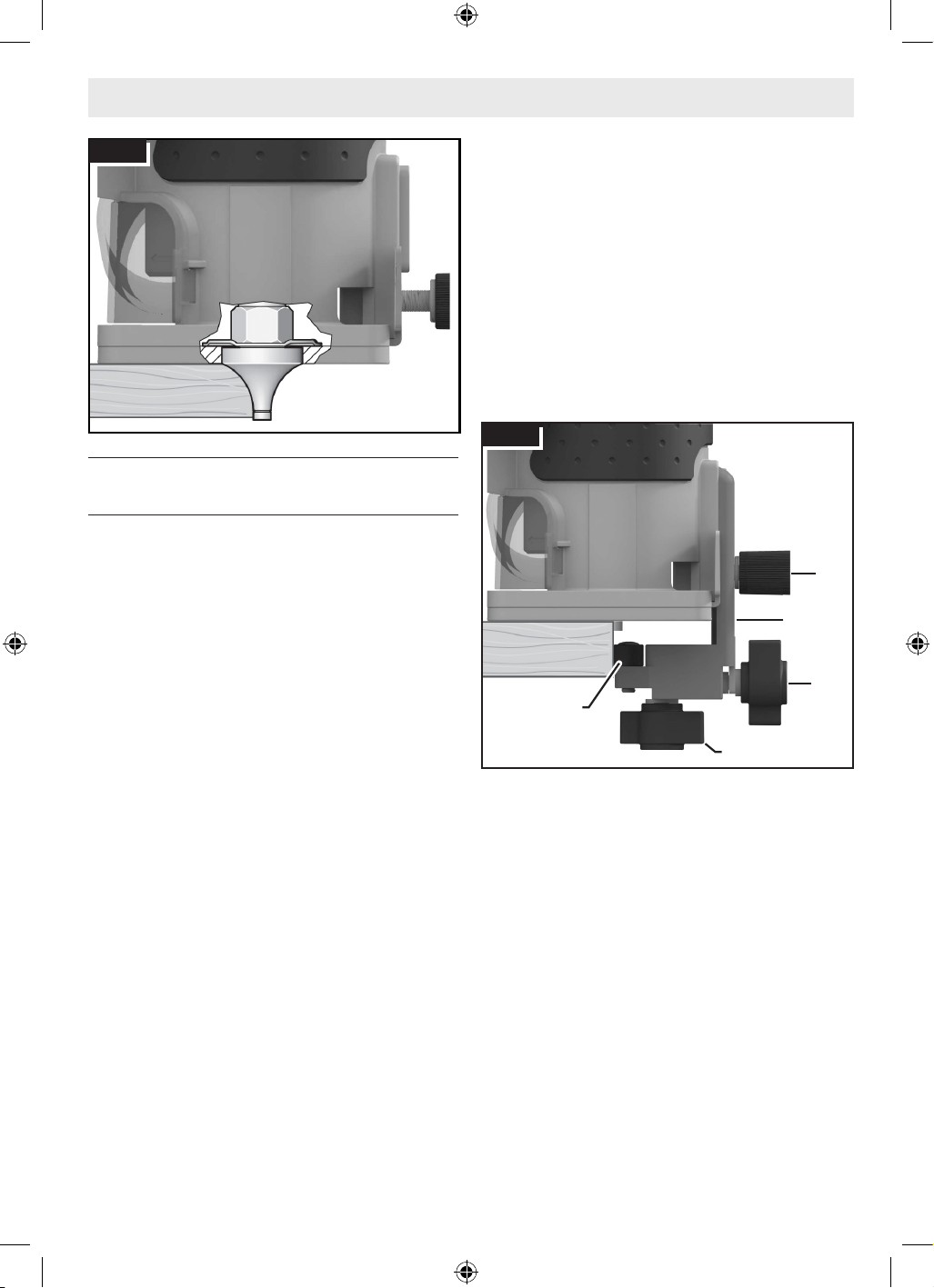
61
Funcionamiento de la herramienta
Utilización de la guía de rodillo/buje (PR003)
(optional accessory)
(Fig. 21)
La guía de rodillo/buje para la base fija 23 opcional se utiliza
cuando se conforman bordes o se recorta con brocas no
pilotadas/sin cojinete.
Siga los pasos de “Instalación de la guía de rodillo/buje
(PR003) (accesorio opcional)” en la página 56 para
instalar la guía.
Ajuste vertical de la guía de rodillo/buje
(Fig. 21)
1. Afloje el tornillo de apriete manual del accesorio trasero
4 y realice ajustes hacia arriba o hacia abajo según sea
necesario para permitir que la guía de rodillo/buje para
la base fija 23 se desplace sobre la superficie de guía
prevista.
2. Apriete el tornillo de apriete manual del accesorio trasero
4.
Ajuste horizontal de la guía de rodillo/buje
(Fig. 21)
Tanto si está haciendo cortes rectos como cortes en bisel, la
anchura del material retirado es determinada por la distancia
entre la parte delantera del cortador de la broca de fresadora
y la parte delantera del rodillo/buje.
Ajuste la parte delantera del rodillo/buje de la manera
siguiente:
1. Afloje la tuerca de mariposa para la alineación horizontal
(parte inferior) 24.
2. Rote la tuerca de mariposa para la alineación horizontal
(parte trasera) 25 para mover el rodillo/buje 26 hacia
dentro o hacia fuera con el fin de crear la cantidad de
exposición del cortador necesaria para recortar el
laminado al ras con la superficie de guía o crear el bisel
deseado.
3. Asegúrese de que la broca sobrepase la parte superior
de la guía de rodillo/buje 23 sin tocarla al menos 1/8 de
pulgada (3 mm) para evitar daños.
4. Apriete la tuerca de mariposa para la alineación horizontal
(parte inferior) 24.
5. Haga un corte de prueba para comprobar la configuración
y reajústela según sea necesario.
Utilización de la guía de rodillo/buje
Con la guía instalada y ajustada, la fresadora se deberá hacer
avanzar normalmente, manteniendo la guía en contacto con la
pieza de trabajo en todo momento.
Para mantener una anchura de corte uniforme, se debe
mantener un ángulo constante entre la fresadora y la pieza de
trabajo.
Fig. 20
4
23
24
25
26
Fig. 21
16099221WG GLF55-25 OSI Final 20250228.indd 6116099221WG GLF55-25 OSI Final 20250228.indd 61 2/28/2025 8:49:35 AM2/28/2025 8:49:35 AM

62
Limpieza
Ciertos agentes de limpieza y solventes dañan las piezas
de plástico. Algunos de estos son: gasolina, tetracloruro
de carbono, solventes de limpieza clorados, amoníaco y
detergentes domésticos que contienen amoníaco.
Elimine periódicamente el polvo de la herramienta limpiándola
con un trapo limpio o usando aire comprimido en el interior
de la unidad de la base y el motor, así como en el sistema de
ajuste de profundidad fino.
Elimine el polvo y los residuos de todas las aberturas de
ventilación. Mantenga la fresadora de trima limpia, seca y
libre de aceite o grasa. Utilice solo un jabón suave y un paño
húmedo para limpiar la fresadora de trima, ya que ciertos
agentes de limpieza y solventes son perjudiciales para los
plásticos y otras piezas con aislamiento. Algunos de estos
incluyen gasolina, trementina, diluyente de laca, diluyente
de pintura, solventes de limpieza clorados, amoníaco y
detergentes domésticos que contienen amoníaco. No
utilice nunca solventes inflamables o combustible cerca de
herramientas.
Almacenamiento y mantenimiento
Almacene la fresadora de palma y los accesorios en un lugar
fresco y seco y evite la congelación. Antes del uso, compruebe
las brocas de fresadora para determinar si tienen grietas y
fracturas, y no las use si se sospecha que están dañadas.
Mantenimiento
Mantenimiento general
Mantenga esta fresadora recortadora y sus accesorios en
buenas condiciones de funcionamiento, adoptando un
programa de mantenimiento regular. Inspeccione la fresadora
recortadora para determinar si hay problemas tales como
ruido indebido, atoramiento de las piezas móviles, rotura
de piezas o cualquier otra situación que pueda afectar al
funcionamiento de la fresadora recortadora.
Servicio de ajustes y reparaciones
Haga que su herramienta eléctrica reciba servicio de ajustes
y reparaciones por un técnico de reparaciones calificado
que utilice únicamente piezas de repuesto idénticas. Esto
garantizará que se mantenga la seguridad de la herramienta
eléctrica.
Lubricacion de las herramientas
Su herramienta Bosch ha sido lubricada adecuadamente y
está lista para la utilización. Se recomienda volver a engrasar
las herramientas con engranajes con un lubricante especial
para engranajes en cada cambio de cepillo.
Escobillas de carbón
Las escobillas y el conmutador de la herramienta han sido
diseñados para muchas horas de servicio fiable. Para
mantener un rendimiento óptimo del motor, recomendamos
que cada dos a seis meses se examinen las esco billas. Sólo se
deben usar escobillas de repuesto Bosch genuinas di señadas
específicamente para su herramienta.
Rodamientos
Todos los rodamientos de esta herramienta están lubricados
con una cantidad suficiente de lubricante de alto grado para
toda la vida útil de la unidad en condiciones de utilización
normales. Por lo tanto, no se requiere lubricación adicional.
Desconecte el enchufe de la fuente de alimentación antes de hacer cualquier ajuste,
cambiar accesorios o almacenar herramientas eléctricas. Dichas medidas preventivas de
seguridad reducen el riesgo de arrancar accidentalmente la herramienta eléctrica.
16099221WG GLF55-25 OSI Final 20250228.indd 6216099221WG GLF55-25 OSI Final 20250228.indd 62 2/28/2025 8:49:35 AM2/28/2025 8:49:35 AM
63
Cordones de extensión
Accesorios
Si es necesario un cordón de extensión, se debe usar un cordón con conductores de tamaño
adecuado que sea capaz de transportar la corriente necesaria para la herramienta. Esto
evitará caídas de tensión excesivas, pérdida de potencia o recalentamiento. Las herramientas conectadas a tierra deben usar
cordones de extensión de 3 hilos que tengan enchufes de 3 terminales y receptáculos para 3 terminales.
NOTA: Cuanto más pequeño sea el número de calibre, más alta será la capacidad del cordón.
Tamaños recomendados de cordones de extension herramientas de 120 v corriente alterna
Capacidad
nominal en
amperes de la
herramienta
Tamaño del cordón en A.W.G. Tamaños del cable en mm
2
Longitud del cordón en pies Longitud del cordón en metros
25 50 100 150 15 30 60 120
3-6 18 16 16 14 0.75 0.75 1.5 2.5
6-8 18 16 14 12 0.75 1.0 2.5 4.0
8-10 18 16 14 12 0.75 1.0 2.5 4.0
10-12 16 16 14 12 1.0 2.5 4.0 –
12-16 14 12 – – – – – –
No utilice aditamentos/accesorios que no sean los especificados por Bosch. Es posible que
el uso de aditamentos/accesorios no especificados para utilizarse con la herramienta descrita en
este manual tenga como resultado daños a la herramienta, daños materiales y/o lesiones corporales.
Accesorio Se incluye
Se vende por
separado
Guía de borde recto • •
Guía de rodillo/buje para la base fija (PR003) • •
Guía de plantilla • •
Cubierta de extracción de polvo (GLF001) • •
Brocas autopilotadas •
Broca de fresadora •
16099221WG GLF55-25 OSI Final 20250228.indd 6316099221WG GLF55-25 OSI Final 20250228.indd 63 2/28/2025 8:49:35 AM2/28/2025 8:49:35 AM
64
Resolución de problemas
Desconecte el enchufe de la fuente de alimentación antes de hacer cualquier ajuste,
cambiar accesorios o almacenar herramientas eléctricas. Dichas medidas preventivas de
seguridad reducen el riesgo de arrancar accidentalmente la herramienta eléctrica.
Problema Causa Medida correctiva
Es difícil controlar la fresadora
recortadora.
Sentido de avance incorrecto.
Invierta el sentido de avance. Consulte
“Avance de la fresadora de trima” en la
página 58.
La fresadora recortadora
funciona lentamente; cortes
bastos, rendimiento de corte
deficiente.
Broca de fresadora desafilada o
dañada.
Reemplace la broca de fresadora.
La fresadora recortadora está
sobrecargada.
Retroceda de la pieza de trabajo para
reducir la carga.
Avance demasiado rápido, ajuste la
velocidad de avance o la configuración de
velocidad de la fresadora de palma.
El corte es demasiado grande para
una pasada. Haga múltiples cortes
progresivamente más profundos.
Quemaduras por fricción en la
pieza de trabajo.
Avance demasiado lento.
Ajuste la velocidad de avance o la
configuración de velocidad de la fresadora
de palma.
16099221WG GLF55-25 OSI Final 20250228.indd 6416099221WG GLF55-25 OSI Final 20250228.indd 64 2/28/2025 8:49:35 AM2/28/2025 8:49:35 AM
65
Licenses
MIT
FreeRTOS, v10.3.1
Copyright (C) 2020 Amazon.com, Inc. or its afliates. All Rights Reserved.
Permission is hereby granted, free of charge, to any person obtaining a copy of this software and associ-
ated documentation les (the "Software"), to deal in the Software without restriction, including without
limitation the rights to use, copy, modify, merge, publish, distribute, sublicense, and/or sell copies of the
Software, and to permit persons to whom the Software is furnished to do so, subject to the following
conditions:
The above copyright notice and this permission notice shall be included in all copies or substantial portions
of the Software.
THE SOFTWARE IS PROVIDED "AS IS", WITHOUT WARRANTY OF ANY KIND, EXPRESS OR IMPLIED, IN-
CLUDING BUT NOT LIMITED TO THE WARRANTIES OF MERCHANTABILITY, FITNESS FOR A PARTICULAR
PURPOSE AND NONINFRINGEMENT. IN NO EVENT SHALL THE AUTHORS OR COPYRIGHT HOLDERS BE LI-
ABLE FOR ANY CLAIM, DAMAGES OR OTHER LIABILITY, WHETHER IN AN ACTION OF CONTRACT, TORT OR
OTHERWISE, ARISING FROM, OUT OF OR IN CONNECTION WITH THE SOFTWARE OR THE USE OR OTHER
DEALINGS IN THE SOFTWARE.
Apache-2.0
GCE-Math, Commit: 8422f5307b0498d09cf626f38acb03fe9f1efd94
Copyright 2016-2023 Keith O'Hara
Licensed under the Apache License, Version 2.0 (the "License");you may not use this le except in compli-
ance with the License.
You may obtain a copy of the License at http://www.apache.org/licenses/LICENSE-2.0
Unless required by applicable law or agreed to in writing, software distributed under the License is dis-
tributed on an "AS IS" BASIS, WITHOUT WARRANTIES OR CONDITIONS OF ANY KIND, either express or
implied. See the License for the specic language governing permissions and limitations under the License.
Apache-2.0
CMSIS_5, v5.9.0
Copyright 2009-2020 Arm Limited. All rights reserved.
Licensed under the Apache License, Version 2.0 (the "License");you may not use this le except in compli-
ance with the License.
You may obtain a copy of the License at http://www.apache.org/licenses/LICENSE-2.0
Unless required by applicable law or agreed to in writing, software distributed under the License is dis-
tributed on an "AS IS" BASIS, WITHOUT WARRANTIES OR CONDITIONS OF ANY KIND, either express or
implied. See the License for the specic language governing permissions and limitations under the License.
BSD-3-Clause
Inneon TLE987x DFP, v1.4.6
Copyright (c) 2015-2017, Inneon Technologies AG. All rights reserved.
Redistribution and use in source and binary forms, with or without modication,are permitted provided that
the following conditions are met:
Redistributions of source code must retain the above copyright notice, this list of conditions and the fol-
lowing disclaimer.
Redistributions in binary form must reproduce the above copyright notice, this list of conditions and the
following disclaimer in the documentation and/or other materials provided with the distribution.
Neither the name of the copyright holders nor the names of its contributors may be used to endorse or
promote products derived from this software without specic prior written permission.
THIS SOFTWARE IS PROVIDED BY THE COPYRIGHT HOLDERS AND CONTRIBUTORS "AS IS" AND ANY
EXPRESS OR IMPLIED WARRANTIES, INCLUDING, BUT NOT LIMITED TO, THE IMPLIED WARRANTIES OF
MERCHANTABILITY AND FITNESS FOR A PARTICULAR PURPOSE ARE DISCLAIMED. IN NO EVENT SHALL
THE COPYRIGHT HOLDER OR CONTRIBUTORS BE LIABLE FOR ANY DIRECT, INDIRECT, INCIDENTAL, SPE-
CIAL, EXEMPLARY, OR CONSEQUENTIAL DAMAGES (INCLUDING, BUT NOT LIMITED TO, PROCUREMENT
16099221WG GLF55-25 OSI Final 20250228.indd 6516099221WG GLF55-25 OSI Final 20250228.indd 65 2/28/2025 8:49:35 AM2/28/2025 8:49:35 AM
66
OF SUBSTITUTE GOODS OR SERVICES; LOSS OF USE, DATA, OR PROFITS; OR BUSINESS INTERRUPTION)
HOWEVER CAUSED AND ON ANY THEORY OF LIABILITY, WHETHER IN CONTRACT, STRICT LIABILITY,OR
TORT (INCLUDING NEGLIGENCE OR OTHERWISE) ARISING IN ANY WAY OUT OF THE USE OF THIS SOFT-
WARE, EVEN IF ADVISED OF THE POSSIBILITY OF SUCH DAMAGE.
BSD-3-Clause
cmsis_device_f0, v2.3.7
Copyright (c) 2016 STMicroelectronics. All rights reserved.
Redistribution and use in source and binary forms, with or without modication, are permitted provided
that the following conditions are met:
1. Redistributions of source code must retain the above copyright notice, this list of conditions and the
following disclaimer.
2. Redistributions in binary form must reproduce the above copyright notice,this list of conditions and the
following disclaimer in the documentation and/or other materials provided with the distribution.
3. Neither the name of the copyright holder nor the names of its contributors may be used to endorse or
promote products derived from this software without specic prior written permission.
THIS SOFTWARE IS PROVIDED BY THE COPYRIGHT HOLDERS AND CONTRIBUTORS "AS IS" AND ANY
EXPRESS OR IMPLIED WARRANTIES, INCLUDING, BUT NOT LIMITED TO, THE IMPLIED WARRANTIES OF
MERCHANTABILITY AND FITNESS FOR A PARTICULAR PURPOSE ARE DISCLAIMED. IN NO EVENT SHALL
THE COPYRIGHT HOLDER OR CONTRIBUTORS BE LIABLE FOR ANY DIRECT, INDIRECT, INCIDENTAL, SPE-
CIAL, EXEMPLARY, OR CONSEQUENTIAL DAMAGES (INCLUDING, BUT NOT LIMITED TO, PROCUREMENT
OF SUBSTITUTE GOODS OR SERVICES; LOSS OF USE, DATA, OR PROFITS; OR BUSINESS INTERRUPTION)
HOWEVER CAUSED AND ON ANY THEORY OF LIABILITY, WHETHER IN CONTRACT, STRICT LIABILITY, OR
TORT (INCLUDING NEGLIGENCE OR OTHERWISE) ARISING IN ANY WAY OUT OF THE USE OF THIS SOFT-
WARE, EVEN IF ADVISED OF THE POSSIBILITY OF SUCH DAMAGE.
Apache-2.0
cmsis_device_g0, v1.4.0
Copyright (c) 2016 STMicroelectronics. All rights reserved.
Licensed under the Apache License, Version 2.0 (the "License");you may not use this le except in compli-
ance with the License.
You may obtain a copy of the License at http://www.apache.org/licenses/LICENSE-2.0
Unless required by applicable law or agreed to in writing, software distributed under the License is dis-
tributed on an "AS IS" BASIS, WITHOUT WARRANTIES OR CONDITIONS OF ANY KIND, either express or
implied.
See the License for the specic language governing permissions and limitations under the License.
MIT
Libxmath, Commit: 24488b16cc0359daada0682a9bd3a11a801d0a01
Copyright (c) 2011-2021 Flatmush <[email protected]>, Petteri Aimonen <Petteri.Aimonen@gmail.
com>, & libxmath AUTHORS libxmath is Copyright (c) 2011-2021 Flatmush <[email protected]>,
Petteri Aimonen <[email protected]>, & libxmath AUTHORS
Permission is hereby granted, free of charge, to any person obtaining a copy of this software and associated
documentation les (the Software), to deal in the Software without restriction, including without limitation
the rights to use, copy, modify, merge, publish, distribute, sublicense, and/or sell copies of the Software,
and to permit persons to whom the Software is furnished to do so, subject to the following conditions:
The above copyright notice and this permission notice shall be included in all copies or substantial portions
of the Software.
THE SOFTWARE IS PROVIDED AS IS, WITHOUT WARRANTY OF ANY KIND, EXPRESS OR IMPLIED, IN-
CLUDING BUT NOT LIMITED TO THE WARRANTIES OF MERCHANTABILITY, FITNESS FOR A PARTICULAR
PURPOSE AND NONINFRINGEMENT. IN NO EVENT SHALL THE AUTHORS OR COPYRIGHT HOLDERS BE LI-
ABLE FOR ANY CLAIM, DAMAGES OR OTHER LIABILITY, WHETHER IN AN ACTION OF CONTRACT, TORT OR
OTHERWISE, ARISING FROM, OUT OF OR IN CONNECTION WITH THE SOFTWARE OR THE USE OR OTHER
DEALINGS IN THE SOFTWARE.
16099221WG GLF55-25 OSI Final 20250228.indd 6616099221WG GLF55-25 OSI Final 20250228.indd 66 2/28/2025 8:49:35 AM2/28/2025 8:49:35 AM
67
MIT
MFixedPoint, v8.0.2
Copyright 2018 Geoffrey Hunter
Permission is hereby granted, free of charge, to any person obtaining a copy of this software and associ-
ated documentation les (the "Software"), to deal in the Software without restriction, including without
limitation the rights to use, copy, modify, merge, publish, distribute, sublicense, and/or sell copies of the
Software, and to permit persons to whom the Software is furnished to do so, subject to the following
conditions:
The above copyright notice and this permission notice shall be included in all copies or substantial portions
of the Software.
THE SOFTWARE IS PROVIDED "AS IS", WITHOUT WARRANTY OF ANY KIND, EXPRESS OR IMPLIED, IN-
CLUDING BUT NOT LIMITED TO THE WARRANTIES OF MERCHANTABILITY, FITNESS FOR A PARTICULAR
PURPOSE AND NONINFRINGEMENT. IN NO EVENT SHALL THE AUTHORS OR COPYRIGHT HOLDERS BE LI-
ABLE FOR ANY CLAIM, DAMAGES OR OTHER LIABILITY, WHETHER IN AN ACTION OF CONTRACT, TORT OR
OTHERWISE, ARISING FROM, OUT OF OR IN CONNECTION WITH THE SOFTWARE OR THE USE OR OTHER
DEALINGS IN THE SOFTWARE.
Zlib
NanoPb, v0.3.9.9
Copyright (c) 2011 Petteri Aimonen <jpa at nanopb.mail.kapsi.>
This software is provided 'as-is', without any express or implied warranty. In no event will the authors be
held liable for any damages arising from the use of this software.
Permission is granted to anyone to use this software for any purpose, including commercial applications,
and to alter it and redistribute it freely, subject to the following restrictions:
1. The origin of this software must not be misrepresented; you must not claim that you wrote the original
software. If you use this software in a product, an acknowledgment in the product documentation would
be appreciated but is not required.
2. Altered source versions must be plainly marked as such, and must not be misrepresented as being the
original software.
3. This notice may not be removed or altered from any source distribution.
newlib, v3.3.0
newlib
v3.3.0
(1) Red Hat Incorporated
Copyright (c) 1994-2009 Red Hat, Inc. All rights reserved.
This copyrighted material is made available to anyone wishing to use, modify, copy, or redistribute it subject
to the terms and conditions of the BSD License. This program is distributed in the hope that it will be
useful, but WITHOUT ANY WARRANTY expressed or implied, including the implied warranties of MER-
CHANTABILITY or FITNESS FOR A PARTICULAR PURPOSE. A copy of this license is available at http://www.
opensource.org/licenses. Any Red Hat trademarks that are incorporated in the source code or documenta-
tion are not subject to the BSD License and may only be used or replicated with the express permission of
Red Hat, Inc.
(2) University of California, Berkeley
Copyright (c) 1981-2000 The Regents of the University of California. All rights reserved.
Redistribution and use in source and binary forms, with or without modication, are permitted provided
that the following conditions are met:
— Redistributions of source code must retain the above copyright notice,this list of conditions and the fol-
lowing disclaimer.
— Redistributions in binary form must reproduce the above copyright notice,this list of conditions and the
following disclaimer in the documentationand/or other materials provided with the distribution.
— Neither the name of the University nor the names of its contributors may be used to endorse or promote
products derived from this software without specic prior written permission.
16099221WG GLF55-25 OSI Final 20250228.indd 6716099221WG GLF55-25 OSI Final 20250228.indd 67 2/28/2025 8:49:35 AM2/28/2025 8:49:35 AM
68
THIS SOFTWARE IS PROVIDED BY THE COPYRIGHT HOLDERS AND CONTRIBUTORS "AS IS" AND ANY
EXPRESS OR IMPLIED WARRANTIES, INCLUDING, BUT NOT LIMITED TO, THE IMPLIED WARRANTIES OF
MERCHANTABILITY AND FITNESS FOR A PARTICULAR PURPOSE ARE DISCLAIMED. IN NO EVENT SHALL
THE COPYRIGHT OWNER OR CONTRIBUTORS BE LIABLE FOR ANY DIRECT, INDIRECT, INCIDENTAL, SPE-
CIAL, EXEMPLARY, OR CONSEQUENTIAL DAMAGES (INCLUDING, BUT NOT LIMITED TO, PROCUREMENT
OF SUBSTITUTE GOODS OR SERVICES; LOSS OF USE, DATA, OR PROFITS; OR BUSINESS INTERRUPTION)
HOWEVER CAUSED AND ON ANY THEORY OF LIABILITY, WHETHER IN CONTRACT, STRICT LIABILITY, OR
TORT (INCLUDING NEGLIGENCE OR OTHERWISE) ARISING IN ANY WAY OUT OF THE USE OF THIS SOFT-
WARE, EVEN IF ADVISED OF THE POSSIBILITY OF SUCH DAMAGE.
(3) David M. Gay (AT&T 1991, Lucent 1998)
David M. Gay, Copyright (c) 1991 by AT&T.
Permission to use, copy, modify, and distribute this software for any purpose without fee is hereby granted,
provided that this entire notice is included in all copies of any software which is or includes a copy or
modication of this software and in all copies of the supporting documentation for such software.
THIS SOFTWARE IS BEING PROVIDED "AS IS", WITHOUT ANY EXPRESS OR IMPLIED WARRANTY. IN
PARTICULAR, NEITHER THE AUTHOR NOR AT&T MAKES ANY REPRESENTATION OR WARRANTY OF ANY
KIND CONCERNING THE MERCHANTABILITY OF THIS SOFTWARE OR ITS FITNESS FOR ANY PARTICULAR
PURPOSE.
(1003) David M. Gay (AT&T 1991, Lucent 1998)
David M. Gay, Copyright (C) 1998-2001 by Lucent Technologies. All Rights Reserved
Permission to use, copy, modify, and distribute this software and its documentation for any purpose and
without fee is hereby granted, provided that the above copyright notice appear in all copies and that both
that the copyright notice and this permission notice and warranty disclaimer appear in supporting docu-
mentation, and that the name of Lucent or any of its entities not be used in advertising or publicity pertain-
ing to distribution of the software without specic, written prior permission.
LUCENT DISCLAIMS ALL WARRANTIES WITH REGARD TO THIS SOFTWARE, INCLUDING ALL IMPLIED WAR-
RANTIES OF MERCHANTABILITY AND FITNESS. IN NO EVENT SHALL LUCENT OR ANY OF ITS ENTITIES BE
LIABLE FOR ANY SPECIAL, INDIRECT OR CONSEQUENTIAL DAMAGES OR ANY DAMAGES WHATSOEVER RE-
SULTING FROM LOSS OF USE, DATA OR PROFITS, WHETHER IN AN ACTION OF CONTRACT, NEGLIGENCE
OR OTHER TORTIOUS ACTION, ARISING OUT OF OR IN CONNECTION WITH THE USE OR PERFORMANCE
OF THIS SOFTWARE.
(4) Advanced Micro Devices
Copyright 1989, 1990 Advanced Micro Devices, Inc.
This software is the property of Advanced Micro Devices, Inc (AMD) which specically grants the user the
right to modify, use and distribute this software provided this notice is not removed or altered.
All other rights are reserved by AMD.
AMD MAKES NO WARRANTY OF ANY KIND, EXPRESS OR IMPLIED, WITH REGARD TO THIS SOFTWARE.
IN NO EVENT SHALL AMD BE LIABLE FOR INCIDENTAL OR CONSEQUENTIAL DAMAGES IN CONNECTION
WITH OR ARISING FROM THE FURNISHING, PERFORMANCE, OR USE OF THIS SOFTWARE.
So that all may benet from your experience, please report any problems or suggestions about this soft-
ware to the 29K Technical Support Center at 800-29-29-AMD (800-292-9263) in the USA, or 0800-89-1131
in the UK, or 0031-11-1129 in Japan, toll free. The direct dial number is 512-462-4118.
Advanced Micro Devices, Inc.
29K Support Products
Mail Stop 573
5900 E. Ben White Blvd.
Austin, TX 78741
800-292-9263
(7) Sun Microsystems
Copyright (C) 1993 by Sun Microsystems, Inc. All rights reserved.
Developed at SunPro, a Sun Microsystems, Inc. business.
Permission to use, copy, modify, and distribute this software is freely granted, provided that this notice is
preserved.
16099221WG GLF55-25 OSI Final 20250228.indd 6816099221WG GLF55-25 OSI Final 20250228.indd 68 2/28/2025 8:49:35 AM2/28/2025 8:49:35 AM
69
(8) Hewlett Packard
(c) Copyright 1986 HEWLETT-PACKARD COMPANY
To anyone who acknowledges that this le is provided "AS IS" without any express or implied warranty:
permission to use, copy, modify, and distribute this le for any purpose is hereby granted without fee, pro-
vided that the above copyright notice and this notice appears in all copies, and that the name of Hewlett-
Packard Company not be used in advertising or publicity pertaining to distribution of the software without
specic, written prior permission. Hewlett-Packard Company makes no representations about the suitability
of this software for any purpose.
(9) Hans-Peter Nilsson
Copyright (C) 2001 Hans-Peter Nilsson
Permission to use, copy, modify, and distribute this software is freely granted, provided that the above
copyright notice, this notice and the following disclaimer are preserved with no changes.
THIS SOFTWARE IS PROVIDED ``AS IS'' AND WITHOUT ANY EXPRESS OR IMPLIED WARRANTIES, INCLUD-
ING, WITHOUT LIMITATION, THE IMPLIED WARRANTIES OF MERCHANTABILITY AND FITNESS FOR A
PARTICULAR PURPOSE.
(11) Christopher G. Demetriou
Copyright (c) 2001 Christopher G. Demetriou. All rights reserved.
Redistribution and use in source and binary forms, with or without modication, are permitted provided
that the following conditions are met:
1. Redistributions of source code must retain the above copyright notice, this list of conditions and the
following disclaimer.
2. Redistributions in binary form must reproduce the above copyright notice, this list of conditions and the
following disclaimer in the documentation and/or other materials provided with the distribution.
3. The name of the author may not be used to endorse or promote products derived from this software
without specic prior written permission.
THIS SOFTWARE IS PROVIDED BY THE AUTHOR ``AS IS'' AND ANY EXPRESS OR IMPLIED WARRANTIES,
INCLUDING, BUT NOT LIMITED TO, THE IMPLIED WARRANTIES OF MERCHANTABILITY AND FITNESS FOR A
PARTICULAR PURPOSE ARE DISCLAIMED. IN NO EVENT SHALL THE AUTHOR BE LIABLE FOR ANY DIRECT,
INDIRECT, INCIDENTAL, SPECIAL, EXEMPLARY, OR CONSEQUENTIAL DAMAGES (INCLUDING, BUT NOT
LIMITED TO, PROCUREMENT OF SUBSTITUTE GOODS OR SERVICES; LOSS OF USE, DATA, OR PROFITS;
OR BUSINESS INTERRUPTION) HOWEVER CAUSED AND ON ANY THEORY OF LIABILITY, WHETHER IN CON-
TRACT, STRICT LIABILITY, OR TORT (INCLUDING NEGLIGENCE OR OTHERWISE) ARISING IN ANY WAY OUT
OF THE USE OF THIS SOFTWARE, EVEN IF ADVISED OF THE POSSIBILITY OF SUCH DAMAGE.
(12) SuperH, Inc.
Copyright 2002 SuperH, Inc. All rights reserved
This software is the property of SuperH, Inc (SuperH) which specically grants the user the right to modify,
use and distribute this software provided this notice is not removed or altered. All other rights are reserved
by SuperH.
SUPERH MAKES NO WARRANTY OF ANY KIND, EXPRESS OR IMPLIED, WITH REGARD TO THIS SOFTWARE.
IN NO EVENT SHALL SUPERH BE LIABLE FOR INDIRECT, SPECIAL, INCIDENTAL OR CONSEQUENTIAL
DAMAGES IN CONNECTION WITH OR ARISING FROM THE FURNISHING, PERFORMANCE, OR USE OF THIS
SOFTWARE.
So that all may benet from your experience, please report any problems or suggestions about this soft-
ware to the SuperH Support Center via e-mail at [email protected] .
SuperH, Inc.
405 River Oaks Parkway
San Jose
CA 95134
USA
(13) Royal Institute of Technology
Copyright (c) 1999 Kungliga Tekniska Högskolan (Royal Institute of Technology, Stockholm, Sweden)
All rights reserved.
Redistribution and use in source and binary forms, with or without modication, are permitted provided
that the following conditions are met:
16099221WG GLF55-25 OSI Final 20250228.indd 6916099221WG GLF55-25 OSI Final 20250228.indd 69 2/28/2025 8:49:35 AM2/28/2025 8:49:35 AM
70
1. Redistributions of source code must retain the above copyright notice, this list of conditions and the
following disclaimer.
2. Redistributions in binary form must reproduce the above copyrightnotice, this list of conditions and the
following disclaimer in the documentation and/or other materials provided with the distribution.
3. Neither the name of KTH nor the names of its contributors may be used to endorse or promote products
derived from this software without specic prior written permission.
THIS SOFTWARE IS PROVIDED BY KTH AND ITS CONTRIBUTORS ``AS IS'' AND ANY EXPRESS OR IMPLIED
WARRANTIES, INCLUDING, BUT NOT LIMITED TO, THE IMPLIED WARRANTIES OF MERCHANTABILITY AND
FITNESS FOR A PARTICULAR PURPOSE ARE DISCLAIMED. IN NO EVENT SHALL KTH OR ITS CONTRIBU-
TORS BE LIABLE FOR ANY DIRECT, INDIRECT, INCIDENTAL, SPECIAL, EXEMPLARY, OR CONSEQUENTIAL
DAMAGES (INCLUDING, BUT NOT LIMITED TO, PROCUREMENT OF SUBSTITUTE GOODS OR SERVICES;
LOSS OF USE, DATA, OR PROFITS; OR BUSINESS INTERRUPTION) HOWEVER CAUSED AND ON ANY
THEORY OF LIABILITY, WHETHER IN CONTRACT, STRICT LIABILITY, OR TORT (INCLUDING NEGLIGENCE OR
OTHERWISE) ARISING IN ANY WAY OUT OF THE USE OF THIS SOFTWARE, EVEN IF ADVISED OF THE POS-
SIBILITY OF SUCH DAMAGE.
(14) Alexey Zelkin
Copyright (c) 2000, 2001 Alexey Zelkin <[email protected]> All rights reserved.
Redistribution and use in source and binary forms, with or without modication, are permitted provided
that the following conditions are met:
1. Redistributions of source code must retain the above copyright notice, this list of conditions and the
following disclaimer.
2. Redistributions in binary form must reproduce the above copyright notice, this list of conditions and the
following disclaimer in the documentation and/or other materials provided with the distribution.
THIS SOFTWARE IS PROVIDED BY THE AUTHOR AND CONTRIBUTORS ``AS IS'' AND ANY EXPRESS OR
IMPLIED WARRANTIES, INCLUDING, BUT NOT LIMITED TO, THE IMPLIED WARRANTIES OF MERCHANT-
ABILITY AND FITNESS FOR A PARTICULAR PURPOSE ARE DISCLAIMED. IN NO EVENT SHALL THE AUTHOR
OR CONTRIBUTORS BE LIABLE FOR ANY DIRECT, INDIRECT, INCIDENTAL, SPECIAL, EXEMPLARY, OR
CONSEQUENTIAL DAMAGES (INCLUDING, BUT NOT LIMITED TO, PROCUREMENT OF SUBSTITUTE GOODS
OR SERVICES; LOSS OF USE, DATA, OR PROFITS; OR BUSINESS INTERRUPTION) HOWEVER CAUSED AND
ON ANY THEORY OF LIABILITY, WHETHER IN CONTRACT, STRICT LIABILITY, OR TORT (INCLUDING NEGLI-
GENCE OR OTHERWISE) ARISING IN ANY WAY OUT OF THE USE OF THIS SOFTWARE, EVEN IF ADVISED OF
THE POSSIBILITY OF SUCH DAMAGE.
(15) Andrey A. Chernov
Copyright (C) 1997 by Andrey A. Chernov, Moscow, Russia. All rights reserved.
Redistribution and use in source and binary forms, with or without modication, are permitted provided
that the following conditions are met:
1. Redistributions of source code must retain the above copyright notice, this list of conditions and the
following disclaimer.
2. Redistributions in binary form must reproduce the above copyright notice, this list of conditions and the
following disclaimer in the documentation and/or other materials provided with the distribution.
THIS SOFTWARE IS PROVIDED BY THE AUTHOR ``AS IS'' AND ANY EXPRESS OR IMPLIED WARRANTIES,
INCLUDING, BUT NOT LIMITED TO, THE IMPLIED WARRANTIES OF MERCHANTABILITY AND FITNESS FOR
A PARTICULAR PURPOSE ARE DISCLAIMED. IN NO EVENT SHALL THE REGENTS OR CONTRIBUTORS BE
LIABLE FOR ANY DIRECT, INDIRECT, INCIDENTAL, SPECIAL, EXEMPLARY, OR CONSEQUENTIAL DAMAGES
(INCLUDING, BUT NOT LIMITED TO, PROCUREMENT OF SUBSTITUTE GOODS OR SERVICES; LOSS OF
USE, DATA, OR PROFITS; OR BUSINESS INTERRUPTION) HOWEVER CAUSED AND ON ANY THEORY OF LI-
ABILITY, WHETHER IN CONTRACT, STRICT LIABILITY, OR TORT (INCLUDING NEGLIGENCE OR OTHERWISE)
ARISING IN ANY WAY OUT OF THE USE OF THIS SOFTWARE, EVEN IF ADVISED OF THE POSSIBILITY OF
SUCH DAMAGE.
(16) FreeBSD
Copyright (c) 1997-2002 FreeBSD Project. All rights reserved.
Redistribution and use in source and binary forms, with or without modication, are permitted provided
that the following conditions are met:
1. Redistributions of source code must retain the above copyright notice, this list of conditions and the
following disclaimer.
16099221WG GLF55-25 OSI Final 20250228.indd 7016099221WG GLF55-25 OSI Final 20250228.indd 70 2/28/2025 8:49:35 AM2/28/2025 8:49:35 AM
71
2. Redistributions in binary form must reproduce the above copyright notice, this list of conditions and the
following disclaimer in the documentation and/or other materials provided with the distribution.
THIS SOFTWARE IS PROVIDED BY THE AUTHOR AND CONTRIBUTORS ``AS IS'' AND ANY EXPRESS OR
IMPLIED WARRANTIES, INCLUDING, BUT NOT LIMITED TO, THE IMPLIED WARRANTIES OF MERCHANT-
ABILITY AND FITNESS FOR A PARTICULAR PURPOSE ARE DISCLAIMED. IN NO EVENT SHALL THE AUTHOR
OR CONTRIBUTORS BE LIABLE FOR ANY DIRECT, INDIRECT, INCIDENTAL, SPECIAL, EXEMPLARY, OR
CONSEQUENTIAL DAMAGES (INCLUDING, BUT NOT LIMITED TO, PROCUREMENT OF SUBSTITUTE GOODS
OR SERVICES; LOSS OF USE, DATA, OR PROFITS; OR BUSINESS INTERRUPTION) HOWEVER CAUSED AND
ON ANY THEORY OF LIABILITY, WHETHER IN CONTRACT, STRICT LIABILITY, OR TORT (INCLUDING NEGLI-
GENCE OR OTHERWISE) ARISING IN ANY WAY OUT OF THE USE OF THIS SOFTWARE, EVEN IF ADVISED OF
THE POSSIBILITY OF SUCH DAMAGE.
(17) S. L. Moshier
Copyright (c) 1984,2000 S.L. Moshier
Permission to use, copy, modify, and distribute this software for any purpose without fee is hereby granted,
provided that this entire notice is included in all copies of any software which is or includes a copy or
modication of this software and in all copies of the supporting documentation for such software.
THIS SOFTWARE IS BEING PROVIDED "AS IS", WITHOUT ANY EXPRESS OR IMPLIED WARRANTY. IN
PARTICULAR, THE AUTHOR MAKES NO REPRESENTATION OR WARRANTY OF ANY KIND CONCERNING THE
MERCHANTABILITY OF THIS SOFTWARE OR ITS FITNESS FOR ANY PARTICULAR PURPOSE.
(18) Citrus Project
Copyright (c)1999 Citrus Project, All rights reserved.
Redistribution and use in source and binary forms, with or without modication, are permitted provided
that the following conditions are met:
1. Redistributions of source code must retain the above copyright notice, this list of conditions and the
following disclaimer.
2. Redistributions in binary form must reproduce the above copyright notice, this list of conditions and the
following disclaimer in the documentation and/or other materials provided with the distribution.
THIS SOFTWARE IS PROVIDED BY THE AUTHOR AND CONTRIBUTORS ``AS IS'' AND ANY EXPRESS OR
IMPLIED WARRANTIES, INCLUDING, BUT NOT LIMITED TO, THE IMPLIED WARRANTIES OF MERCHANT-
ABILITY AND FITNESS FOR A PARTICULAR PURPOSE ARE DISCLAIMED. IN NO EVENT SHALL THE AUTHOR
OR CONTRIBUTORS BE LIABLE FOR ANY DIRECT, INDIRECT, INCIDENTAL, SPECIAL, EXEMPLARY, OR
CONSEQUENTIAL DAMAGES (INCLUDING, BUT NOT LIMITED TO, PROCUREMENT OF SUBSTITUTE GOODS
OR SERVICES; LOSS OF USE, DATA, OR PROFITS; OR BUSINESS INTERRUPTION) HOWEVER CAUSED AND
ON ANY THEORY OF LIABILITY, WHETHER IN CONTRACT, STRICT LIABILITY, OR TORT (INCLUDING NEGLI-
GENCE OR OTHERWISE) ARISING IN ANY WAY OUT OF THE USE OF THIS SOFTWARE, EVEN IF ADVISED OF
THE POSSIBILITY OF SUCH DAMAGE.
(19) Todd C. Miller
Copyright (c) 1998 Todd C. Miller <[email protected]> All rights reserved.
Redistribution and use in source and binary forms, with or without modication, are permitted provided
that the following conditions are met:
1. Redistributions of source code must retain the above copyright notice, this list of conditions and the
following disclaimer.
2. Redistributions in binary form must reproduce the above copyright notice, this list of conditions and the
following disclaimer in the documentation and/or other materials provided with the distribution.
3. The name of the author may not be used to endorse or promote products derived from this software
without specic prior written permission.
THIS SOFTWARE IS PROVIDED ``AS IS'' AND ANY EXPRESS OR IMPLIED WARRANTIES, INCLUDING, BUT
NOT LIMITED TO, THE IMPLIED WARRANTIES OF MERCHANTABILITY AND FITNESS FOR A PARTICULAR
PURPOSE ARE DISCLAIMED. IN NO EVENT SHALL THE AUTHOR BE LIABLE FOR ANY DIRECT, INDIRECT,
INCIDENTAL, SPECIAL, EXEMPLARY, OR CONSEQUENTIAL DAMAGES (INCLUDING, BUT NOT LIMITED TO,
PROCUREMENT OF SUBSTITUTE GOODS OR SERVICES; LOSS OF USE, DATA, OR PROFITS; OR BUSINESS
INTERRUPTION) HOWEVER CAUSED AND ON ANY THEORY OF LIABILITY, WHETHER IN CONTRACT, STRICT
LIABILITY, OR TORT (INCLUDING NEGLIGENCE OR OTHERWISE) ARISING IN ANY WAY OUT OF THE USE OF
THIS SOFTWARE, EVEN IF ADVISED OF THE POSSIBILITY OF SUCH DAMAGE.
16099221WG GLF55-25 OSI Final 20250228.indd 7116099221WG GLF55-25 OSI Final 20250228.indd 71 2/28/2025 8:49:35 AM2/28/2025 8:49:35 AM
72
(26) Mike Barcroft
Copyright (c) 2001 Mike Barcroft <[email protected]> All rights reserved.
Redistribution and use in source and binary forms, with or without modication, are permitted provided
that the following conditions are met:
1. Redistributions of source code must retain the above copyright notice, this list of conditions and the
following disclaimer.
2. Redistributions in binary form must reproduce the above copyright notice, this list of conditions and the
following disclaimer in the documentation and/or other materials provided with the distribution.
THIS SOFTWARE IS PROVIDED BY THE AUTHOR AND CONTRIBUTORS ``AS IS'' AND ANY EXPRESS OR
IMPLIED WARRANTIES, INCLUDING, BUT NOT LIMITED TO, THE IMPLIED WARRANTIES OF MERCHANT-
ABILITY AND FITNESS FOR A PARTICULAR PURPOSE ARE DISCLAIMED. IN NO EVENT SHALL THE AUTHOR
OR CONTRIBUTORS BE LIABLE FOR ANY DIRECT, INDIRECT, INCIDENTAL, SPECIAL, EXEMPLARY, OR
CONSEQUENTIAL DAMAGES (INCLUDING, BUT NOT LIMITED TO, PROCUREMENT OF SUBSTITUTE GOODS
OR SERVICES; LOSS OF USE, DATA, OR PROFITS; OR BUSINESS INTERRUPTION) HOWEVER CAUSED AND
ON ANY THEORY OF LIABILITY, WHETHER IN CONTRACT, STRICT LIABILITY, OR TORT (INCLUDING NEGLI-
GENCE OR OTHERWISE) ARISING IN ANY WAY OUT OF THE USE OF THIS SOFTWARE, EVEN IF ADVISED OF
THE POSSIBILITY OF SUCH DAMAGE.
(35) - ARM Ltd (arm and thumb variant targets only)
Copyright (c) 2009-2015 ARM Ltd All rights reserved.
Redistribution and use in source and binary forms, with or without modication, are permitted provided
that the following conditions are met:
1. Redistributions of source code must retain the above copyright notice, this list of conditions and the
following disclaimer.
2. Redistributions in binary form must reproduce the above copyright notice, this list of conditions and the
following disclaimer in the documentation and/or other materials provided with the distribution.
3. The name of the company may not be used to endorse or promote products derived from this software
without specic prior written permission.
THIS SOFTWARE IS PROVIDED BY ARM LTD ``AS IS'' AND ANY EXPRESS OR IMPLIED WARRANTIES,
INCLUDING, BUT NOT LIMITED TO, THE IMPLIED WARRANTIES OF MERCHANTABILITY AND FITNESS FOR
A PARTICULAR PURPOSE ARE DISCLAIMED. IN NO EVENT SHALL ARM LTD BE LIABLE FOR ANY DIRECT,
INDIRECT, INCIDENTAL, SPECIAL, EXEMPLARY, OR CONSEQUENTIAL DAMAGES (INCLUDING, BUT NOT
LIMITED TO, PROCUREMENT OF SUBSTITUTE GOODS OR SERVICES; LOSS OF USE, DATA, OR PROFITS;
OR BUSINESS INTERRUPTION) HOWEVER CAUSED AND ON ANY THEORY OF LIABILITY, WHETHER IN CON-
TRACT, STRICT LIABILITY, OR TORT (INCLUDING NEGLIGENCE OR OTHERWISE) ARISING IN ANY WAY OUT
OF THE USE OF THIS SOFTWARE, EVEN IF ADVISED OF THE POSSIBILITY OF SUCH DAMAGE.
(41) Ed Schouten - Free BSD
Copyright (c) 2008 Ed Schouten <[email protected]> All rights reserved.
Redistribution and use in source and binary forms, with or without modication, are permitted provided
that the following conditions are met:
1. Redistributions of source code must retain the above copyright notice, this list of conditions and the
following disclaimer.
2. Redistributions in binary form must reproduce the above copyright notice, this list of conditions and the
following disclaimer in the documentation and/or other materials provided with the distribution.
THIS SOFTWARE IS PROVIDED BY THE AUTHOR AND CONTRIBUTORS ``AS IS'' AND ANY EXPRESS OR
IMPLIED WARRANTIES, INCLUDING, BUT NOT LIMITED TO, THE IMPLIED WARRANTIES OF MERCHANT-
ABILITY AND FITNESS FOR A PARTICULAR PURPOSE ARE DISCLAIMED. IN NO EVENT SHALL THE AUTHOR
OR CONTRIBUTORS BE LIABLE FOR ANY DIRECT, INDIRECT, INCIDENTAL, SPECIAL, EXEMPLARY, OR
CONSEQUENTIAL DAMAGES (INCLUDING, BUT NOT LIMITED TO, PROCUREMENT OF SUBSTITUTE GOODS
OR SERVICES; LOSS OF USE, DATA, OR PROFITS; OR BUSINESS INTERRUPTION) HOWEVER CAUSED AND
ON ANY THEORY OF LIABILITY, WHETHER IN CONTRACT, STRICT LIABILITY, OR TORT (INCLUDING NEGLI-
GENCE OR OTHERWISE) ARISING IN ANY WAY OUT OF THE USE OF THIS SOFTWARE, EVEN IF ADVISED OF
THE POSSIBILITY OF SUCH DAMAGE.
16099221WG GLF55-25 OSI Final 20250228.indd 7216099221WG GLF55-25 OSI Final 20250228.indd 72 2/28/2025 8:49:35 AM2/28/2025 8:49:35 AM
73
(46) Synopsis
Copyright (c) 2016, Synopsys, Inc. All rights reserved.
Redistribution and use in source and binary forms, with or without modication, are permitted provided
that the following conditions are met:
1. Redistributions of source code must retain the above copyright notice, this list of conditions and the
following disclaimer.
2. Redistributions in binary form must reproduce the above copyright notice, this list of conditions and the
following disclaimer in the documentation and/or other materials provided with the distribution.
3. Neither the name of the Synopsys, Inc., nor the names of its contributors may be used to endorse or
promote products derived from this software without specic prior written permission.
THIS SOFTWARE IS PROVIDED BY THE COPYRIGHT HOLDERS AND CONTRIBUTORS "AS IS" AND ANY
EXPRESS OR IMPLIED WARRANTIES, INCLUDING, BUT NOT LIMITED TO, THE IMPLIED WARRANTIES OF
MERCHANTABILITY AND FITNESS FOR A PARTICULAR PURPOSE ARE DISCLAIMED. IN NO EVENT SHALL
THE COPYRIGHT HOLDER OR CONTRIBUTORS BE LIABLE FOR ANY DIRECT, INDIRECT, INCIDENTAL, SPE-
CIAL, EXEMPLARY, OR CONSEQUENTIAL DAMAGES (INCLUDING, BUT NOT LIMITED TO, PROCUREMENT
OF SUBSTITUTE GOODS OR SERVICES; LOSS OF USE, DATA, OR PROFITS; OR BUSINESS INTERRUPTION)
HOWEVER CAUSED AND ON ANY THEORY OF LIABILITY, WHETHER IN CONTRACT, STRICT LIABILITY, OR
TORT (INCLUDING NEGLIGENCE OR OTHERWISE) ARISING IN ANY WAY OUT OF THE USE OF THIS SOFT-
WARE, EVEN IF ADVISED OF THE POSSIBILITY OF SUCH DAMAGE.
(47) Joel Sherrill
Copyright (c) 2016 Joel Sherrill <[email protected]>. All rights reserved.
Redistribution and use in source and binary forms, with or without modication, are permitted provided
that the following conditions are met:
1. Redistributions of source code must retain the above copyright notice, this list of conditions and the
following disclaimer.
2. Redistributions in binary form must reproduce the above copyright notice, this list of conditions and the
following disclaimer in the documentation and/or other materials provided with the distribution.
THIS SOFTWARE IS PROVIDED BY THE AUTHOR AND CONTRIBUTORS ``AS IS'' AND ANY EXPRESS OR
IMPLIED WARRANTIES, INCLUDING, BUT NOT LIMITED TO, THE IMPLIED WARRANTIES OF MERCHANT-
ABILITY AND FITNESS FOR A PARTICULAR PURPOSE ARE DISCLAIMED. IN NO EVENT SHALL THE AUTHOR
OR CONTRIBUTORS BE LIABLE FOR ANY DIRECT, INDIRECT, INCIDENTAL, SPECIAL, EXEMPLARY, OR
CONSEQUENTIAL DAMAGES (INCLUDING, BUT NOT LIMITED TO, PROCUREMENT OF SUBSTITUTE GOODS
OR SERVICES; LOSS OF USE, DATA, OR PROFITS; OR BUSINESS INTERRUPTION) HOWEVER CAUSED AND
ON ANY THEORY OF LIABILITY, WHETHER IN CONTRACT, STRICT LIABILITY, OR TORT (INCLUDING NEGLI-
GENCE OR OTHERWISE) ARISING IN ANY WAY OUT OF THE USE OF THIS SOFTWARE, EVEN IF ADVISED OF
THE POSSIBILITY OF SUCH DAMAGE.
(48) From musl include/elf.h
Copyright (c) 2005-2014 Rich Felker, et al.t
Permission is hereby granted, free of charge, to any person obtaining a copy of this software and associ-
ated documentation les (the "Software"), to deal in the Software without restriction, including without
limitation the rights to use, copy, modify, merge, publish, distribute, sublicense, and/or sell copies of the
Software, and to permit persons to whom the Software is furnished to do so, subject to the following
conditions:
The above copyright notice and this permission notice shall be included in all copies or substantial portions
of the Software.
THE SOFTWARE IS PROVIDED "AS IS", WITHOUT WARRANTY OF ANY KIND, EXPRESS OR IMPLIED, IN-
CLUDING BUT NOT LIMITED TO THE WARRANTIES OF MERCHANTABILITY, FITNESS FOR A PARTICULAR
PURPOSE AND NONINFRINGEMENT. IN NO EVENT SHALL THE AUTHORS OR COPYRIGHT HOLDERS BE LI-
ABLE FOR ANY CLAIM, DAMAGES OR OTHER LIABILITY, WHETHER IN AN ACTION OF CONTRACT, TORT OR
OTHERWISE, ARISING FROM, OUT OF OR IN CONNECTION WITH THE SOFTWARE OR THE USE OR OTHER
DEALINGS IN THE SOFTWARE.
(49) Moerbeek
Copyright (c) 2008 Otto Moerbeek <[email protected]>
Permission to use, copy, modify, and distribute this software for any purpose with or without fee is hereby
granted, provided that the above copyright notice and this permission notice appear in all copies.
16099221WG GLF55-25 OSI Final 20250228.indd 7316099221WG GLF55-25 OSI Final 20250228.indd 73 2/28/2025 8:49:35 AM2/28/2025 8:49:35 AM
74
THE SOFTWARE IS PROVIDED "AS IS" AND THE AUTHOR DISCLAIMS ALL WARRANTIES WITH REGARD
TO THIS SOFTWARE INCLUDING ALL IMPLIED WARRANTIES OF MERCHANTABILITY AND FITNESS. IN NO
EVENT SHALL THE AUTHOR BE LIABLE FOR ANY SPECIAL, DIRECT, INDIRECT, OR CONSEQUENTIAL DAM-
AGES OR ANY DAMAGES WHATSOEVER RESULTING FROM LOSS OF USE, DATA OR PROFITS, WHETHER IN
AN ACTION OF CONTRACT, NEGLIGENCE OR OTHER TORTIOUS ACTION, ARISING OUT OF OR IN CONNEC-
TION WITH THE USE OR PERFORMANCE OF THIS SOFTWARE.
(50) embedded brains
Copyright (c) 2017 embedded brains GmbH All rights reserved.
Redistribution and use in source and binary forms, with or without modication, are permitted provided
that the following conditions are met:
1. Redistributions of source code must retain the above copyright notice, this list of conditions and the
following disclaimer.
2. Redistributions in binary form must reproduce the above copyright notice, this list of conditions and the
following disclaimer in the documentation and/or other materials provided with the distribution.
THIS SOFTWARE IS PROVIDED BY THE AUTHOR AND CONTRIBUTORS ``AS IS'' AND ANY EXPRESS OR
IMPLIED WARRANTIES, INCLUDING, BUT NOT LIMITED TO, THE IMPLIED WARRANTIES OF MERCHANT-
ABILITY AND FITNESS FOR A PARTICULAR PURPOSE ARE DISCLAIMED. IN NO EVENT SHALL THE AUTHOR
OR CONTRIBUTORS BE LIABLE FOR ANY DIRECT, INDIRECT, INCIDENTAL, SPECIAL, EXEMPLARY, OR
CONSEQUENTIAL DAMAGES (INCLUDING, BUT NOT LIMITED TO, PROCUREMENT OF SUBSTITUTE GOODS
OR SERVICES; LOSS OF USE, DATA, OR PROFITS; OR BUSINESS INTERRUPTION) HOWEVER CAUSED AND
ON ANY THEORY OF LIABILITY, WHETHER IN CONTRACT, STRICT LIABILITY, OR TORT (INCLUDING NEGLI-
GENCE OR OTHERWISE) ARISING IN ANY WAY OUT OF THE USE OF THIS SOFTWARE, EVEN IF ADVISED OF
THE POSSIBILITY OF SUCH DAMAGE.
(51) From musl src/string/strverscmp.c
Copyright (c) 2005-2014 Rich Felker, et al.
Permission is hereby granted, free of charge, to any person obtaining a copy of this software and associ-
ated documentation les (the "Software"), to deal in the Software without restriction, including without
limitation the rights to use, copy, modify, merge, publish, distribute, sublicense, and/or sell copies of the
Software, and to permit persons to whom the Software is furnished to do so, subject to the following
conditions:
The above copyright notice and this permission notice shall be included in all copies or substantial portions
of the Software.
THE SOFTWARE IS PROVIDED "AS IS", WITHOUT WARRANTY OF ANY KIND, EXPRESS OR IMPLIED, IN-
CLUDING BUT NOT LIMITED TO THE WARRANTIES OF MERCHANTABILITY, FITNESS FOR A PARTICULAR
PURPOSE AND NONINFRINGEMENT. IN NO EVENT SHALL THE AUTHORS OR COPYRIGHT HOLDERS BE LI-
ABLE FOR ANY CLAIM, DAMAGES OR OTHER LIABILITY, WHETHER IN AN ACTION OF CONTRACT, TORT OR
OTHERWISE, ARISING FROM, OUT OF OR IN CONNECTION WITH THE SOFTWARE OR THE USE OR OTHER
DEALINGS IN THE SOFTWARE.
(52) ucla1
Copyright (c) 1983, 1993 The Regents of the University of California. All rights reserved.
Redistribution and use in source and binary forms, with or without modication, are permitted provided
that the following conditions are met:
1. Redistributions of source code must retain the above copyright notice, this list of conditions and the
following disclaimer.
2. Redistributions in binary form must reproduce the above copyright notice, this list of conditions and the
following disclaimer in the documentation and/or other materials provided with the distribution.
3. Neither the name of the University nor the names of its contributors may be used to endorse or promote
products derived from this software without specic prior written permission.
THIS SOFTWARE IS PROVIDED BY THE REGENTS AND CONTRIBUTORS ``AS IS'' AND ANY EXPRESS OR IM-
PLIED WARRANTIES, INCLUDING, BUT NOT LIMITED TO, THE IMPLIED WARRANTIES OF MERCHANTABILITY
AND FITNESS FOR A PARTICULAR PURPOSE ARE DISCLAIMED. IN NO EVENT SHALL THE REGENTS OR
CONTRIBUTORS BE LIABLE FOR ANY DIRECT, INDIRECT, INCIDENTAL, SPECIAL, EXEMPLARY, OR CONSE-
QUENTIAL DAMAGES (INCLUDING, BUT NOT LIMITED TO, PROCUREMENT OF SUBSTITUTE GOODS OR
SERVICES; LOSS OF USE, DATA, OR PROFITS; OR BUSINESS INTERRUPTION) HOWEVER CAUSED AND ON
ANY THEORY OF LIABILITY, WHETHER IN CONTRACT, STRICT LIABILITY, OR TORT (INCLUDING NEGLI-
16099221WG GLF55-25 OSI Final 20250228.indd 7416099221WG GLF55-25 OSI Final 20250228.indd 74 2/28/2025 8:49:35 AM2/28/2025 8:49:35 AM
75
GENCE OR OTHERWISE) ARISING IN ANY WAY OUT OF THE USE OF THIS SOFTWARE, EVEN IF ADVISED OF
THE POSSIBILITY OF SUCH DAMAGE.
(1052) diged
Portions Copyright (c) 1993 by Digital Equipment Corporation.
Permission to use, copy, modify, and distribute this software for any purpose with or without fee is hereby
granted, provided that the above copyright notice and this permission notice appear in all copies, and that
the name of Digital Equipment Corporation not be used in advertising or publicity pertaining to distribution
of the document or software without specic, written prior permission.
THE SOFTWARE IS PROVIDED "AS IS" AND DIGITAL EQUIPMENT CORP. DISCLAIMS ALL WARRANTIES
WITH REGARD TO THIS SOFTWARE, INCLUDING ALL IMPLIED WARRANTIES OF MERCHANTABILITY AND
FITNESS. IN NO EVENT SHALL DIGITAL EQUIPMENT CORPORATION BE LIABLE FOR ANY SPECIAL,
DIRECT, INDIRECT, OR CONSEQUENTIAL DAMAGES OR ANY DAMAGES WHATSOEVER RESULTING FROM
LOSS OF USE, DATA OR PROFITS, WHETHER IN AN ACTION OF CONTRACT, NEGLIGENCE OR OTHER
TORTIOUS ACTION, ARISING OUT OF OR IN CONNECTION WITH THE USE OR PERFORMANCE OF THIS
SOFTWARE.
(53) freebsd
Copyright (c) 2015 John Baldwin <[email protected]>. All rights reserved.
Redistribution and use in source and binary forms, with or without modication, are permitted provided
that the following conditions are met:
1. Redistributions of source code must retain the above copyright notice, this list of conditions and the
following disclaimer.
2. Redistributions in binary form must reproduce the above copyright notice, this list of conditions and the
following disclaimer in the documentation and/or other materials provided with the distribution.
3. Neither the name of the author nor the names of its contributors may be used to endorse or promote
products derived from this software without specic prior written permission.
THIS SOFTWARE IS PROVIDED BY THE REGENTS AND CONTRIBUTORS ``AS IS'' AND ANY EXPRESS OR IM-
PLIED WARRANTIES, INCLUDING, BUT NOT LIMITED TO, THE IMPLIED WARRANTIES OF MERCHANTABIL-
ITY AND FITNESS FOR A PARTICULAR PURPOSE ARE DISCLAIMED. IN NO EVENT SHALL THE REGENTS OR
CONTRIBUTORS BE LIABLE FOR ANY DIRECT, INDIRECT, INCIDENTAL, SPECIAL, EXEMPLARY, OR CONSE-
QUENTIAL DAMAGES (INCLUDING, BUT NOT LIMITED TO, PROCUREMENT OF SUBSTITUTE GOODS OR
SERVICES; LOSS OF USE, DATA, OR PROFITS; OR BUSINESS INTERRUPTION) HOWEVER CAUSED AND ON
ANY THEORY OF LIABILITY, WHETHER IN CONTRACT, STRICT LIABILITY, OR TORT (INCLUDING NEGLI-
GENCE OR OTHERWISE) ARISING IN ANY WAY OUT OF THE USE OF THIS SOFTWARE, EVEN IF ADVISED OF
THE POSSIBILITY OF SUCH DAMAGE.
(54) WIDE
Copyright (C) 1995, 1996, 1997, and 1998 WIDE Project. All rights reserved.
Redistribution and use in source and binary forms, with or without modication, are permitted provided
that the following conditions are met:
1. Redistributions of source code must retain the above copyright notice, this list of conditions and the
following disclaimer.
2. Redistributions in binary form must reproduce the above copyright notice, this list of conditions and the
following disclaimer in the documentation and/or other materials provided with the distribution.
3. Neither the name of the project nor the names of its contributors may be used to endorse or promote
products derived from this software without specic prior written permission.
THIS SOFTWARE IS PROVIDED BY THE PROJECT AND CONTRIBUTORS ``AS IS'' AND ANY EXPRESS OR
IMPLIED WARRANTIES, INCLUDING, BUT NOT LIMITED TO, THE IMPLIED WARRANTIES OF MERCHANT-
ABILITY AND FITNESS FOR A PARTICULAR PURPOSE ARE DISCLAIMED. IN NO EVENT SHALL THE PROJ-
ECT OR CONTRIBUTORS BE LIABLE FOR ANY DIRECT, INDIRECT, INCIDENTAL, SPECIAL, EXEMPLARY, OR
CONSEQUENTIAL DAMAGES (INCLUDING, BUT NOT LIMITED TO, PROCUREMENT OF SUBSTITUTE GOODS
OR SERVICES; LOSS OF USE, DATA, OR PROFITS; OR BUSINESS INTERRUPTION) HOWEVER CAUSED AND
ON ANY THEORY OF LIABILITY, WHETHER IN CONTRACT, STRICT LIABILITY, OR TORT (INCLUDING NEGLI-
GENCE OR OTHERWISE) ARISING IN ANY WAY OUT OF THE USE OF THIS SOFTWARE, EVEN IF ADVISED OF
THE POSSIBILITY OF SUCH DAMAGE.
16099221WG GLF55-25 OSI Final 20250228.indd 7516099221WG GLF55-25 OSI Final 20250228.indd 75 2/28/2025 8:49:35 AM2/28/2025 8:49:35 AM
76
(55) Roberson
Copyright (c) 2008, Jeffrey Roberson <[email protected]> All rights reserved. Copyright (c) 2008 Nokia
Corporation All rights reserved.
Redistribution and use in source and binary forms, with or without modication, are permitted provided
that the following conditions are met:\
1. Redistributions of source code must retain the above copyright notice unmodied, this list of conditions,
and the following disclaimer.
2. Redistributions in binary form must reproduce the above copyright notice, this list of conditions and the
following disclaimer in the documentation and/or other materials provided with the distribution.
THIS SOFTWARE IS PROVIDED BY THE AUTHOR ``AS IS'' AND ANY EXPRESS OR IMPLIED WARRANTIES,
INCLUDING, BUT NOT LIMITED TO, THE IMPLIED WARRANTIES OF MERCHANTABILITY AND FITNESS FOR A
PARTICULAR PURPOSE ARE DISCLAIMED. IN NO EVENT SHALL THE AUTHOR BE LIABLE FOR ANY DIRECT,
INDIRECT, INCIDENTAL, SPECIAL, EXEMPLARY, OR CONSEQUENTIAL DAMAGES (INCLUDING, BUT NOT
LIMITED TO, PROCUREMENT OF SUBSTITUTE GOODS OR SERVICES; LOSS OF USE, DATA, OR PROFITS;
OR BUSINESS INTERRUPTION) HOWEVER CAUSED AND ON ANY THEORY OF LIABILITY, WHETHER IN CON-
TRACT, STRICT LIABILITY, OR TORT (INCLUDING NEGLIGENCE OR OTHERWISE) ARISING IN ANY WAY OUT
OF THE USE OF THIS SOFTWARE, EVEN IF ADVISED OF THE POSSIBILITY OF SUCH DAMAGE.
(56) ucla3
Copyright (c) 1982, 1986, 1990, 1993, 1994 The Regents of the University of California. All rights re-
served. (c) UNIX System Laboratories, Inc.
All or some portions of this le are derived from material licensed to the University of California by Ameri-
can Telephone and Telegraph Co. or Unix System Laboratories, Inc. and are reproduced herein with the
permission of UNIX System Laboratories, Inc. Redistribution and use in source and binary forms, with or
without modication, are permitted provided that the following conditions are met:
1. Redistributions of source code must retain the above copyright notice, this list of conditions and the
following disclaimer.
2. Redistributions in binary form must reproduce the above copyright notice, this list of conditions and the
following disclaimer in the documentation and/or other materials provided with the distribution.
3. Neither the name of the University nor the names of its contributors may be used to endorse or promote
products derived from this software without specic prior written permission.
THIS SOFTWARE IS PROVIDED BY THE REGENTS AND CONTRIBUTORS ``AS IS'' AND ANY EXPRESS OR IM-
PLIED WARRANTIES, INCLUDING, BUT NOT LIMITED TO, THE IMPLIED WARRANTIES OF MERCHANTABILITY
AND FITNESS FOR A PARTICULAR PURPOSE ARE DISCLAIMED. IN NO EVENT SHALL THE REGENTS OR
CONTRIBUTORS BE LIABLE FOR ANY DIRECT, INDIRECT, INCIDENTAL, SPECIAL, EXEMPLARY, OR CONSE-
QUENTIAL DAMAGES (INCLUDING, BUT NOT LIMITED TO, PROCUREMENT OF SUBSTITUTE GOODS OR
SERVICES; LOSS OF USE, DATA, OR PROFITS; OR BUSINESS INTERRUPTION) HOWEVER CAUSED AND ON
ANY THEORY OF LIABILITY, WHETHER IN CONTRACT, STRICT LIABILITY, OR TORT (INCLUDING NEGLI-
GENCE OR OTHERWISE) ARISING IN ANY WAY OUT OF THE USE OF THIS SOFTWARE, EVEN IF ADVISED OF
THE POSSIBILITY OF SUCH DAMAGE.
(57) Conguration for math routines.
Copyright (c) 2017 ARM Ltd. All rights reserved.
Redistribution and use in source and binary forms, with or without modication, are permitted provided
that the following conditions are met:
1. Redistributions of source code must retain the above copyright notice, this list of conditions and the
following disclaimer.
2. Redistributions in binary form must reproduce the above copyright notice, this list of conditions and the
following disclaimer in the documentation and/or other materials provided with the distribution.
3. The name of the company may not be used to endorse or promote products derived from this software
without specic prior written permission.
THIS SOFTWARE IS PROVIDED BY ARM LTD ``AS IS AND ANY EXPRESS OR IMPLIED WARRANTIES,
INCLUDING, BUT NOT LIMITED TO, THE IMPLIED WARRANTIES OF MERCHANTABILITY AND FITNESS FOR
A PARTICULAR PURPOSE ARE DISCLAIMED. IN NO EVENT SHALL ARM LTD BE LIABLE FOR ANY DIRECT,
INDIRECT, INCIDENTAL, SPECIAL, EXEMPLARY, OR CONSEQUENTIAL DAMAGES (INCLUDING, BUT NOT
LIMITED TO, PROCUREMENT OF SUBSTITUTE GOODS OR SERVICES; LOSS OF USE, DATA, OR PROFITS;
OR BUSINESS INTERRUPTION) HOWEVER CAUSED AND ON ANY THEORY OF LIABILITY, WHETHER IN CON-
16099221WG GLF55-25 OSI Final 20250228.indd 7616099221WG GLF55-25 OSI Final 20250228.indd 76 2/28/2025 8:49:35 AM2/28/2025 8:49:35 AM
77
TRACT, STRICT LIABILITY, OR TORT (INCLUDING NEGLIGENCE OR OTHERWISE) ARISING IN ANY WAY OUT
OF THE USE OF THIS SOFTWARE, EVEN IF ADVISED OF THE POSSIBILITY OF SUCH DAMAGE.
(58) netbsd
Copyright (c) 2007 The NetBSD Foundation, Inc. All rights reserved.
This code is derived from software written by Stephen L. Moshier. It is redistributed by the NetBSD Founda-
tion by permission of the author.
Redistribution and use in source and binary forms, with or without modication, are permitted provided
that the following conditions are met:
1. Redistributions of source code must retain the above copyright notice, this list of conditions and the
following disclaimer.
2. Redistributions in binary form must reproduce the above copyright notice, this list of conditions and the
following disclaimer in the documentation and/or other materials provided with the distribution.
THIS SOFTWARE IS PROVIDED BY THE NETBSD FOUNDATION, INC. AND CONTRIBUTORS ``AS IS'' AND
ANY EXPRESS OR IMPLIED WARRANTIES, INCLUDING, BUT NOT LIMITED TO, THE IMPLIED WARRANTIES
OF MERCHANTABILITY AND FITNESS FOR A PARTICULAR PURPOSE ARE DISCLAIMED. IN NO EVENT
SHALL THE FOUNDATION OR CONTRIBUTORS BE LIABLE FOR ANY DIRECT, INDIRECT, INCIDENTAL, SPE-
CIAL, EXEMPLARY, OR CONSEQUENTIAL DAMAGES (INCLUDING, BUT NOT LIMITED TO, PROCUREMENT
OF SUBSTITUTE GOODS OR SERVICES; LOSS OF USE, DATA, OR PROFITS; OR BUSINESS INTERRUPTION)
HOWEVER CAUSED AND ON ANY THEORY OF LIABILITY, WHETHER IN CONTRACT, STRICT LIABILITY, OR
TORT (INCLUDING NEGLIGENCE OR OTHERWISE) ARISING IN ANY WAY OUT OF THE USE OF THIS SOFT-
WARE, EVEN IF ADVISED OF THE POSSIBILITY OF SUCH DAMAGE.
(59) neilly
(c) Copyright 2017 Michael R. Neilly All rights reserved.
Redistribution and use in source and binary forms, with or without modication, are permitted provided
that the following conditions are met:
— Redistributions of source code must retain the above copyright notice, this list of conditions and the
following disclaimer.
— Redistributions in binary form must reproduce the above copyright notice, this list of conditions and the
following disclaimer in the documentation and/or other materials provided with the distribution.
— Neither the names of the copyright holders nor the names of their contributors may be used to endorse
or promote products derived from this software without specic prior written permission.
THIS SOFTWARE IS PROVIDED BY THE COPYRIGHT HOLDERS AND CONTRIBUTORS "AS IS" AND ANY
EXPRESS OR IMPLIED WARRANTIES, INCLUDING, BUT NOT LIMITED TO, THE IMPLIED WARRANTIES OF
MERCHANTABILITY AND FITNESS FOR A PARTICULAR PURPOSE ARE DISCLAIMED. IN NO EVENT SHALL
THE COPYRIGHT OWNER OR CONTRIBUTORS BE LIABLE FOR ANY DIRECT, INDIRECT, INCIDENTAL, SPE-
CIAL, EXEMPLARY, OR CONSEQUENTIAL DAMAGES (INCLUDING, BUT NOT LIMITED TO, PROCUREMENT
OF SUBSTITUTE GOODS OR SERVICES; LOSS OF USE, DATA, OR PROFITS; OR BUSINESS INTERRUPTION)
HOWEVER CAUSED AND ON ANY THEORY OF LIABILITY, WHETHER IN CONTRACT, STRICT LIABILITY, OR
TORT (INCLUDING NEGLIGENCE OR OTHERWISE) ARISING IN ANY WAY OUT OF THE USE OF THIS SOFT-
WARE, EVEN IF ADVISED OF THE POSSIBILITY OF SUCH DAMAGE.
(114) - National Semiconductor Corporation
Copyright (c) 2004 National Semiconductor Corporation
The authors hereby grant permission to use, copy, modify, distribute, and license this software and its doc-
umentation for any purpose, provided that existing copyright notices are retained in all copies and that this
notice is included verbatim in any distributions. No written agreement, license, or royalty fee is required for
any of the authorized uses. Modications to this software may be copyrighted by their authors and need
not follow the licensing terms described here, provided that the new terms are clearly indicated on the rst
page of each le where they apply.
Generic License Text
Apache 2.0 License
Apache License
Version 2.0, January 2004
http://www.apache.org/licenses/
TERMS AND CONDITIONS FOR USE, REPRODUCTION, AND DISTRIBUTION
16099221WG GLF55-25 OSI Final 20250228.indd 7716099221WG GLF55-25 OSI Final 20250228.indd 77 2/28/2025 8:49:35 AM2/28/2025 8:49:35 AM
78
1. Denitions.
"License" shall mean the terms and conditions for use, reproduction, and distribution as dened by Sec-
tions 1 through 9 of this document.
"Licensor" shall mean the copyright owner or entity authorized by the copyright owner that is granting the
License.
"Legal Entity" shall mean the union of the acting entity and all other entities that control, are controlled
by, or are under common control with that entity. For the purposes of this denition, "control" means (i)
the power, direct or indirect, to cause the direction or management of such entity, whether by contract
or otherwise, or (ii) ownership of fty percent (50%) or more of the outstanding shares, or (iii) benecial
ownership of such entity.
"You" (or "Your") shall mean an individual or Legal Entity exercising permissions granted by this License.
"Source" form shall mean the preferred form for making modications, including but not limited to soft-
ware source code, documentation source, and conguration les.
"Object" form shall mean any form resulting from mechanical transformation or translation of a Source
form, including but not limited to compiled object code, generated documentation, and conversions to
other media types.
"Work" shall mean the work of authorship, whether in Source or Object form, made available under the
License, as indicated by a copyright notice that is included in or attached to the work (an example is pro-
vided in the Appendix below).
"Derivative Works" shall mean any work, whether in Source or Object form, that is based on (or derived
from) the Work and for which the editorial revisions, annotations, elaborations, or other modications
represent, as a whole, an original work of authorship. For the purposes of this License, Derivative Works
shall not include works that remain separable from, or merely link (or bind by name) to the interfaces of,
the Work and Derivative Works thereof.
"Contribution" shall mean any work of authorship, including the original version of the Work and any modi-
cations or additions to that Work or Derivative Works thereof, that is intentionally submitted to Licensor
for inclusion in the Work by the copyright owner or by an individual or Legal Entity authorized to submit on
behalf of the copyright owner. For the purposes of this denition, "submitted" means any form of electron-
ic, verbal, or written communication sent to the Licensor or its representatives, including but not limited
to communication on electronic mailing lists, source code control systems, and issue tracking systems that
are managed by, or on behalf of, the Licensor for the purpose of discussing and improving the Work, but
excluding communication that is conspicuously marked or otherwise designated in writing by the copyright
owner as "Not a Contribution."
"Contributor" shall mean Licensor and any individual or Legal Entity on behalf of whom a Contribution has
been received by Licensor and subsequently incorporated within the Work.
2. Grant of Copyright License. Subject to the terms and conditions of this License, each Contributor here-
by grants to You a perpetual, worldwide, non-exclusive, no-charge, royalty-free, irrevocable copyright license
to reproduce, prepare Derivative Works of, publicly display, publicly perform, sublicense, and distribute the
Work and such Derivative Works in Source or Object form.
3. Grant of Patent License. Subject to the terms and conditions of this License, each Contributor hereby
grants to You a perpetual, worldwide, non-exclusive, no-charge, royalty-free, irrevocable (except as stated in
this section) patent license to make, have made, use, offer to sell, sell, import, and otherwise transfer the
Work, where such license applies only to those patent claims licensable by such Contributor that are neces-
sarily infringed by their Contribution(s) alone or by combination of their Contribution(s) with the Work to
which such Contribution(s) was submitted. If You institute patent litigation against any entity (including a
cross-claim or counterclaim in a lawsuit) alleging that the Work or a Contribution incorporated within the
Work constitutes direct or contributory patent infringement, then any patent licenses granted to You under
this License for that Work shall terminate as of the date such litigation is led.
4. Redistribution. You may reproduce and distribute copies of the Work or Derivative Works thereof in any
medium, with or without modications, and in Source or Object form, provided that You meet the following
conditions:
— You must give any other recipients of the Work or Derivative Works a copy of this License; and
— You must cause any modied les to carry prominent notices stating that You changed the les; and
— You must retain, in the Source form of any Derivative Works that You distribute, all copyright, patent,
trademark, and attribution notices from the Source form of the Work, excluding those notices that do not
pertain to any part of the Derivative Works; and
16099221WG GLF55-25 OSI Final 20250228.indd 7816099221WG GLF55-25 OSI Final 20250228.indd 78 2/28/2025 8:49:35 AM2/28/2025 8:49:35 AM
79
— If the Work includes a "NOTICE" text le as part of its distribution, then any Derivative Works that You
distribute must include a readable copy of the attribution notices contained within such NOTICE le,
excluding those notices that do not pertain to any part of the Derivative Works, in at least one of the
following places: within a NOTICE text le distributed as part of the Derivative Works; within the Source
form or documentation, if provided along with the Derivative Works; or, within a display generated by the
Derivative Works, if and wherever such third-party notices normally appear. The contents of the NOTICE
le are for informational purposes only and do not modify the License. You may add Your own attribution
notices within Derivative Works that You distribute, alongside or as an addendum to the NOTICE text from
the Work, provided that such additional attribution notices cannot be construed as modifying the License.
You may add Your own copyright statement to Your modications and may provide additional or different
license terms and conditions for use, reproduction, or distribution of Your modications, or for any such
Derivative Works as a whole, provided Your use, reproduction, and distribution of the Work otherwise
complies with the conditions stated in this License.
5. Submission of Contributions. Unless You explicitly state otherwise, any Contribution intentionally
submitted for inclusion in the Work by You to the Licensor shall be under the terms and conditions of this
License, without any additional terms or conditions. Notwithstanding the above, nothing herein shall super-
sede or modify the terms of any separate license agreement you may have executed with Licensor regarding
such Contributions.
6. Trademarks. This License does not grant permission to use the trade names, trademarks, service marks,
or product names of the Licensor, except as required for reasonable and customary use in describing the
origin of the Work and reproducing the content of the NOTICE le.
7. Disclaimer of Warranty. Unless required by applicable law or agreed to in writing, Licensor provides the
Work (and each Contributor provides its Contributions) on an "AS IS" BASIS, WITHOUT WARRANTIES OR
CONDITIONS OF ANY KIND, either express or implied, including, without limitation, any warranties or con-
ditions of TITLE, NON-INFRINGEMENT, MERCHANTABILITY, or FITNESS FOR A PARTICULAR PURPOSE. You
are solely responsible for determining the appropriateness of using or redistributing the Work and assume
any risks associated with Your exercise of permissions under this License.
8. Limitation of Liability. In no event and under no legal theory, whether in tort (including negligence),
contract, or otherwise, unless required by applicable law (such as deliberate and grossly negligent acts) or
agreed to in writing, shall any Contributor be liable to You for damages, including any direct, indirect, spe-
cial, incidental, or consequential damages of any character arising as a result of this License or out of the
use or inability to use the Work (including but not limited to damages for loss of goodwill, work stoppage,
computer failure or malfunction, or any and all other commercial damages or losses), even if such Contribu-
tor has been advised of the possibility of such damages.
9. Accepting Warranty or Additional Liability. While redistributing the Work or Derivative Works thereof,
You may choose to offer, and charge a fee for, acceptance of support, warranty, indemnity, or other liability
obligations and/or rights consistent with this License. However, in accepting such obligations, You may act
only on Your own behalf and on Your sole responsibility, not on behalf of any other Contributor, and only if
You agree to indemnify, defend, and hold each Contributor harmless for any liability incurred by, or claims
asserted against, such Contributor by reason of your accepting any such warranty or additional liability.
END OF TERMS AND CONDITIONS
Warranty Disclaimer
This product contains Open Source Software components which underly Open Source Software Licenses.
Please note that Open Source Licenses contain disclaimer clauses. The text of the Open Source Licenses
that apply are included in this manual under "Licenses".
16099221WG GLF55-25 OSI Final 20250228.indd 7916099221WG GLF55-25 OSI Final 20250228.indd 79 2/28/2025 8:49:35 AM2/28/2025 8:49:35 AM

16099221WG 02/2025
© Robert Bosch Tool Corporation
1800 W. Central Road
Mt. Prospect, IL 60056-2230
!16099221WG!
LIMITED WARRANTY
For details on the terms of the limited warranty for this product, go to https://rb-pt.io/PowerToolWarranty or
call 1-877-BOSCH99.
GARANTIE LIMITÉE
Pour tous détails sur les conditions de la garantie limitée pour ce produit, allez sur le site https://rb-pt.io/PowerToolWarranty ou téléphonez au
1-877-BOSCH99.
GARANTÍA LIMITADA
Para obtener detalles sobre los términos de la garantía limitada de este producto, visite https://rb-pt.io/PowerToolWarranty o llame al
1-877-BOSCH99.
16099221WG GLF55-25 OSI Final 20250228.indd 8016099221WG GLF55-25 OSI Final 20250228.indd 80 2/28/2025 8:49:35 AM2/28/2025 8:49:35 AM