Triton V2 UL Natural-cooling Dispenser
Technical Manual

V 1.0.0 Star
1
Legal Notice
This document is an integral part of the technical documentation and is protected by copyright.
Without written consent, any use outside the strict limits of copyright law is prohibited. This also
applies to files that are duplicated, translated, and photographed, and files that are stored and
processed using electronic media. Any party who violates this provision will be liable for
compensation claims!
The information presented in this guide is subject to change without prior notice.
The technical specifications indicated here do not constitute a contractual obligation.
In case of any doubt regarding a subject described or if you discover an error in this manual, please
contact us.
Split Charging System

V 1.0.0 Star
2
Contents
Legal Notice.......................................................................................................................................................................1
Contents............................................................................................................................................................................. 2
Abbreviations....................................................................................................................................................................6
1 Introduction.................................................................................................................................................................... 7
1.1 Function of this document............................................................................................................................ 7
1.2 Target user.........................................................................................................................................................7
1.3 Version and revision history......................................................................................................................... 7
1.4 Disclaimer...........................................................................................................................................................8
1.5 Copyright............................................................................................................................................................8
1.6 Warranty............................................................................................................................................................ 9
1.7 Supplier............................................................................................................................................................... 9
1.7.1 Europe.....................................................................................................................................................9
1.7.2 APAC.......................................................................................................................................................9
1.7.3 Americas..............................................................................................................................................10
2 Safety............................................................................................................................................................................ 12
2.1 General safety................................................................................................................................................12
2.2 Safety symbols.............................................................................................................................................. 13
2.3 Environmental conditions........................................................................................................................... 13
2.4 Engineer requirements................................................................................................................................ 14
2.4.1 Normal requirements.......................................................................................................................14
2.4.2 Responsibility requirements..........................................................................................................14
2.4.3 Skill requirements............................................................................................................................. 14
2.5 Safety guidelines for installation personnel......................................................................................... 15
2.6 Fire safety guidelines for construction sites......................................................................................... 16
2.7 Fire emergency response plans............................................................................................................... 16
2.7.1 Initiation of the plan......................................................................................................................... 16
2.7.2 Contingency procedures................................................................................................................ 16
2.7.3 Concluding fire emergency response.........................................................................................17
2.8 Disposal............................................................................................................................................................17
2.9 Emergency stop.............................................................................................................................................18
3 Product overview.......................................................................................................................................................19
3.1 Nameplate.......................................................................................................................................................19
3.2 External view..................................................................................................................................................21
4 Transport, storage, and unpacking..................................................................................................................... 23
4.1 Transport to the site..................................................................................................................................... 23
4.2 Store the equipment.....................................................................................................................................23
4.3 Unpacking inspection.................................................................................................................................. 24

V 1.0.0 Star
3
4.3.1 Unpacking list.................................................................................................................................... 24
4.3.2 Inspection of unpacking..................................................................................................................25
5 Installation................................................................................................................................................................... 26
5.1 Prerequisites...................................................................................................................................................26
5.2 Site preparation............................................................................................................................................. 26
5.2.1 Space requirements between EVSE and obstacles..............................................................27
5.2.2 Communication distance requirements.................................................................................... 28
5.2.3 Airflow requirements....................................................................................................................... 28
5.2.4 Canopy requirements......................................................................................................................28
5.3 Cable preparation......................................................................................................................................... 30
5.4 Site preparation............................................................................................................................................. 30
5.4.1 Wall mounted site requirements...............................................................错误!未定义书签。
5.4.2 Gantry mounted site requirements.......................................................... 错误!未定义书签。
5.5 Grounding/insulation resistance check.................................................................................................. 30
5.6 Hoisting............................................................................................................................................................ 31
5.7 Fixing.............................................................................................................................. 错误!未定义书签。
5.7.1 Wall mounted fixing...................................................................................... 错误!未定义书签。
5.7.2 Gantry mounted fixing..................................................................................错误!未定义书签。
5.8 Electrical installation.................................................................................................................................... 34
5.8.1 Electrical schematic diagram........................................................................................................34
5.8.2 Cable wiring....................................................................................................................................... 36
5.9 Check after installation................................................................................................................................40
5.9.1 Installation and wiring check........................................................................................................ 40
5.9.2 Check before power on the EVSE............................................................................................... 40
5.9.3 Check on power-on......................................................................................................................... 41
5.10 Completion information............................................................................................................................41
5.11 Appendix.......................................................................................................................................................42
Appendix 1 Unpacking Record Sheet...................................................................................................42
Appendix 2 Pre-installation Checklist.................................................................................................. 43
Appendix 3 Post-installation Checklist................................................................................................ 44
6 Commissioning...........................................................................................................................................................45
6.1 Prerequisites...................................................................................................................................................45
6.2 Commissioning flowchart...........................................................................................................................46
6.3 Installation recheck.......................................................................................................................................47
6.4 EVSE power on and check......................................................................................................................... 47
6.4.1 Pre-power-on check........................................................................................................................47
6.4.2 EVSE Power on ................................................................................................................................. 51
6.4.3 Recheck after power on................................................................................................................. 53

V 1.0.0 Star
4
6.5 Laptop configuration....................................................................................................................................53
6.6 Login web UI with the preset password............................................................................................... 56
6.7 The unique IP address setting of the user unit....................................................................................58
6.7.1 RealGunID configuration (Important)......................................................................................... 58
6.7.2 Login to the charger via the unique IP address...................................................................... 61
6.8 OCPP connection.......................................................................................................................................... 62
6.9 Introduction to the User Unit Web UI..................................................................................................... 62
6.9.1 Verify the status of the user unit..................................................................................................62
6.9.2 Basic configuration setting of the user unit..............................................................................65
6.9.3 Charger configuration (Optional).................................................................................................68
6.9.4 Debug Assistant (Optional)........................................................................................................... 72
6.9.5 Upload (Optional)..............................................................................................................................73
6.9.6 Account Management.................................................................................................................... 74
6.10 Manually upgrade firmware................................................................................................................... 74
6.10.1 Update SECC via Micro SD card...............................................................................................74
6.10.2 Update Multifunction Control board (CB02)/PDU control board/Environmental
monitoring board via Micro SD card......................................................................................................78
6.10.3 Update AM62 board via Micro SD card................................................................................. 82
6.11 Charging function check.......................................................................................................................... 85
6.11.1 Charging testing.............................................................................................................................85
6.11.2 Hardware function check............................................................................................................ 85
6.11.3 Liquid cooling device charging test....................................................... 错误!未定义书签。
6.12 Customer training.......................................................................................................................................86
6.13 Appendix.......................................................................................................................................................87
Appendix 1 Post-installation Checklist................................................................................................ 87
Appendix 2 Customer Training Record Sheet................................................................................... 88
Appendix 3 Commissioning Report.......................................................................................................89
Appendix 4 Required tools for commission........................................................................................ 97
7 Preventive Maintenance......................................................................................................................................... 99
7.1 External and environmental checks..................................................................................................... 100
7.2 Functionality checks and tests...............................................................................................................102
7.3 Charging connector inspection.............................................................................................................. 103
7.4 Electrical checks and tests...................................................................................................................... 104
7.5 New Electric Vehicles (EV) / e-buses interoperability tests.......................................................... 104
7.6 Charging test............................................................................................................................................... 105
8 Corrective Maintenance........................................................................................................................................106
8.1 Could not access web panel.................................................................................................................. 106
8.2 No network connection............................................................................................................................ 107

V 1.0.0 Star
5
8.3 EVSE is offline..............................................................................................................................................109
8.4 Power module communication fault.................................................................................................... 110
8.5 No response after plug in........................................................................................................................ 115
8.6 Meter communication failure.................................................................................................................. 118
8.7 Input under-voltage fault......................................................................................................................... 119
8.8 Input over-voltage fault............................................................................................................................119
8.9 Insulation fault............................................................................................................................................. 120
8.10 User unit door is open............................................................................................................................ 121
8.11 No effective current output...................................................................................................................122
8.12 No response after swiping a card...................................................................................................... 123
8.13 Cannot reach the maximum output capacity.................................................................................124
8.14 Cooling fan malfunction.........................................................................................................................124
8.15 Power supply is normal, PCB boards are not on...........................................................................124
8.16 Output over current................................................................................................................................. 125
8.17 With voltage but no current................................................................................................................. 125
8.18 MCCB disconnected............................................................................................................................... 125
8.19 Input surge protection alarm................................................................................................................126
9 Technical specifications........................................................................................................................................127
9.1 Technical data.............................................................................................................................................127
9.1.1 General parameters...................................................................................................................... 127
9.1.2 Input parameters and grid parameters.................................................................................. 127
9.1.3 Output parameters........................................................................................................................ 127
9.1.4 Environmental parameters......................................................................................................... 127
9.1.5 Communication parameters.......................................................................................................128
9.1.6 User Interface & control............................................................................................................... 128
9.1.7 Mechanical parameters............................................................................................................... 128
9.2 Required tools..............................................................................................................................................129
9.2.1 Required tools for installation.................................................................................................... 129
9.2.3 Bolts recommended Torque reference sheet........................................................................131
9.4 Compliance and standard adhered to................................................................................................ 132
9.4.1 Certification......................................................................................................................................132
9.4.2 Standards......................................................................................................................................... 132
Customer service........................................................................................................................................................ 133

V 1.0.0 Star
6
Abbreviations
AC Alternating Current
GBT Guobiao Recommended Standard
CCS1 Combined Charging System 1
CCS2 Combined Charging System 2
NACS North American Charging Standard
CMS Cable Management System
CP Control Pilot
DC Direct Current
EV Electric Vehicle
EVSE Electric Vehicle Supply Equipment
IMD Insulation Monitoring Device
LED Light Emitting Diode
MCB Miniature Circuit Breaker
MCCB Molded Case Circuit Breaker
OCPP Open Charge Point Protocol
PDU Power Distribution Unit
PSU Power Supply Unit
RCBO Residual Current Circuit Breaker with Overcurrent Protection Device
RFID Radio Frequency Identification
SPD Surge Protective Device
SECC Supply Equipment Communication Controller
UI User Interface

V 1.0.0 Star
7
1 Introduction
1.1 Function of this document
This manual is only for the charging system, a type of equipment that charges Electric Vehicles (EV).
This manual tells you how to safely:
Install the Electric Vehicle Supply Equipment (EVSE).
Commission the EVSE for the first time.
Perform basic maintenance tasks.
1.2 Target user
This manual is for:
EVSE owners: These are people who own and operate the EVSE for commercial or business
purposes, or who may allow others to use it. EVSE owners are legally responsible for
protecting users, other employees, and third parties while the EVSE is in operation.
Qualified engineers: These are people who are fully familiar with the EVSE and are
responsible for installing, operating, commissioning, and maintaining it. Qualified engineers
should have knowledge of electrical safety, understand the principles and performance of
chargers, and follow all local rules and instructions in this manual.
1.3 Version and revision history
The version of this document is V1.0.0 and the revision history is as follows.
Version
Date
Description
V 1.0.0
First edition
Table 1-1 Version of the technical manual

V 1.0.0 Star
8
1.4 Disclaimer
This manual was carefully reviewed by experts before it was published. It will be updated
regularly to include any necessary changes or additions.
The information in this manual is for informational purposes only.
This manual, related manuals, and warnings do not replace your responsibility to use common
sense when working with the EVSE.
StarCharge has done its best to make sure the manuals are accurate and up to date, but they
are not responsible for any problems or damage that may come from using the information in
them.
StarCharge is not responsible for any direct, indirect, special, or consequential damage
(including loss of profits) that may come from any errors or omissions in this manual. All of
StarCharge's obligations are stated in the relevant contracts. StarCharge reserves the right to
change this manual from time to time.
Any changes to the EVSE, including but not limited to user-specific modifications to the EVSE
(such as placing stickers, SIM cards, or using different colors), hereinafter referred to as
"Customization", may affect the final product's user experience, appearance, quality, and/or
lifespan.
StarCharge is not responsible for any damage to or caused by the product "Customization "
and is not responsible for any damage, losses, costs, or expenses resulting from the improper
handling of the product.
Contact your dealer for more information on "Customization " versus the default product.
1.5 Copyright
All rights reserved. The disclosure, duplication, distribution and editing of this document, or
utilization and communication of the content are not permitted, unless authorized in writing. All
rights, including rights created by patent grant or registration of a utility model or a design, are
reserved.
V 1.0.0 Star
9
1.6 Warranty
The warranty period is defined in your warranty policy. If you have purchased an extended
warranty, the warranty period is defined in your purchase agreement.
The warranty only covers the product and its parts delivered by StarCharge. The warranty does not
cover consumable parts such as cables and connectors, any other materials, labor, accommodation,
or travel costs.
Changes or modifications to the equipment, unless specifically agreed upon with StarCharge, will
void the warranty.
When you replace parts under warranty, keep the old parts until you know that
StarCharge does not need them for inspection.
Installation, operation, commissioning, and maintenance tasks should only be
done by the people described in Chapter 1.2. If someone who is not authorized
to do these tasks does them, the warranty may be void.
1.7 Supplier
1.7.1 Europe
StarCharge Europe GmbH
Am Prime Parc 17, 3.OG, Raunheim 65479, Germany
Customer service hotline: +44 20 7096 1752
Customer service E-mail: Service.europe@starcharge.com
Homepage: www.starcharge.com
1.7.2 APAC
StarCharge Energy Pte., Ltd.
1 Harbourfront Pl, 04-09; Singapore 098633
Customer service hotline: +60 15 4600 0603
Global customer service E-mail: service.global@starcharge.com
Homepage: www.starcharge.com


V 1.0.0 Star
11

V 1.0.0 Star
12
2 Safety
The charging system from StarCharge is only meant to be used for charging EVs. To use it safely
and properly, it is important to follow the instructions in this manual and on the EVSE itself, as well
as all local rules and regulations.
This EVSE has been developed, manufactured, inspected, and filed in accordance with all relevant
safety standards. Therefore, if you can follow the instructions and safety tips for installation,
commissioning, and maintenance, the EVSE will not cause property damage or harm your health
under normal circumstances.
2.1 General safety
Do not use the EVSE:
○ Near explosives or flammable substances.
○ In or near water.
○ If it is visibly damaged.
Do not clean the EVSE with running water or a pressure washer.
Do not change or modify the EVSE unless StarCharge has approved of it.
Do not wrap the cables around the EVSE while charging.
Do not put the connector on the ground. Put it in its holder after charging.
Only do things that are described in this manual or the related manual, and that you are
qualified to do.
Follow the safety rules and accident prevention rules for the EVSE and the area where it is
used.
Make sure the EVSE is used in the environmental conditions that are specified for it. For more
information about environmental conditions, refer to Chapter 6.1.4.
Only qualified electricians (StarCharge certified partners) should install, operate, commission,
and maintain the EVSE.
All installation and wiring must be done when the AC cables are not energized. This means
that the EVSE cannot be turned on during this process. This helps to prevent electrical
accidents, short circuits, and electric shock hazards. It makes sure that the system is not turned
on during risky procedures, which reduces the chance of fires during installation or
maintenance.
When handling electrical connections, always follow safety protocols, wear the necessary
personal protective equipment (PPE), and use insulated tools.
Follow the local rules and the instructions in this manual. If any requirements in this manual are
not the same as the local rules, follow the local rules or the stricter of the two, as allowed by
law.
V 1.0.0 Star
13
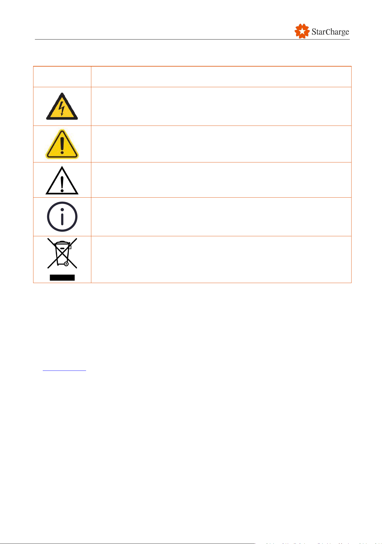
2.2 Safety symbols
Symbols
Meanings
Electric hazard: This symbol indicates that there is a danger of electric shock.
Failure to pay attention to the procedures, practices or improper implementation
may cause injuries or death.
Caution: This symbol indicates that there is a hazard that could damage the
product.
Warning: This symbol calls attention to an act or condition which CAN lead to
serious personal injury or death if not avoided.
Tips: This symbol indicates that the information is helpful or provides useful
advice. It does not contain any information about danger or harm.
Garbage disposal: This symbol indicates that the electrical and electronic
equipment and their accessories should be disposed of separately from
household waste.
Table 2-1 Safety symbols
2.3 Environmental conditions
You must use the EVSE in the environmental conditions that are specified for it. This is important for
the EVSE to work properly and safely. For more information about environmental conditions, refer
to Chapter 6.1.4.

V 1.0.0 Star
14
2.4 Engineer requirements
2.4.1 Normal requirements
Engineers responsible for installation, operation, commissioning, and maintenance should:
Be trained in safety and job skills and pass any corresponding assessments.
Follow the local rules and the instructions in this manual. If any requirements in this manual
are different from the local rules, follow the local rules or the stricter of the two, as required
by law.
Learn the electrical safety requirements and how to do first aid and emergency treatment
for electric shock.
○ If there is a safety accident, immediately start the emergency plan and report it to the
relevant person in charge. Also, provide first aid and emergency treatment according to
the plan, control the spread of the issue, and rescue people and property.
○ If there is an electric shock, immediately shut off the power and assist the person using
the approved emergency rescue method. At the same time, call for professional help,
report to the relevant person in charge, and make a record.
Strictly follow the operating procedures and job specifications when working to ensure
safety and stability.
Wear a uniform, insulated shoes and gloves, a safety helmet, and other protective gear if
necessary. Also make sure there is a valid work permit if required,
Be responsible for their work and fulfill their service commitments to the best of their abilities.
Communicate with customers in a professional and courteous manner using clear and
concise language.
2.4.2 Responsibility requirements
Engineers responsible for EVSE installation, operation, commissioning, and maintenance are
accountable for:
Making sure the EVSE is safe to use
Improving the EVSE’s safety system
Regularly checking the EVSE for safety issues
Monitoring and reporting on the EVSE's safety status
2.4.3 Skill requirements
Engineers responsible for EVSE installation, operation, commissioning, and maintenance should:
Understand how EVs and EVSEs work, how to troubleshoot common problems, how to
maintain EVSEs, how to handle emergencies, and safety knowledge.
Be familiar with the relevant national safety rules and regulations and understand charging

V 1.0.0 Star
15
safety and emergency procedures.
2.5 Safety guidelines for installation personnel
Safety:
○ Follow the safety rules of the construction site.
○ Wear a properly fastened safety helmet and make sure it is in good condition.
○ Do not wear unsafe clothing, such as loose clothes or slippers.
○ Do not go to work inebriated.
Working at heights:
○ Always wear a safety helmet and ensure it is properly fastened, fasten your safety belt,
and wear non-slip shoes.
○ Tie up your work tools.
○ Be careful when entering areas such as foundation pits, roofs, and openings to prevent
accidental falls.
Protective measures:
○ If there is heavy dust at the construction site or painting work is being done, wear a
protective mask.
○ Do not enter dangerous areas where materials are being lifted above you.
○ Do not strike objects.
○ Stay away from mechanical equipment and electrical circuits to prevent accidents.
When using portable power tools:
○ Make sure you know how to use the tools safely.
○ Wear insulated shoes and gloves.
○ Make sure the tools are properly grounded.
Temporary electricity:
○ Replace damaged electrical components immediately.
○ Temporary wires must be made of rubber cables, not plastic flexible cords.
○ Do not plug temporary wires directly into sockets.
○ Do not use temporary electrical components when they are live.
Ground conditions:
○ Be careful of ground conditions with iron nails and steel bars.
○ This is to prevent injuries such as piercing, touching, hanging, and falling.
Site maintenance:
○ Do not dismantle construction site protection facilities, safety signs, and warning signs
without permission.
○ Maintain construction equipment in good condition.
○ This is to prevent malfunctions or overload operation.
EVSE usage: Keep the door of the EVSE closed after installing it to prevent water intrusion from

V 1.0.0 Star
16
rain.
2.6 Fire safety guidelines for construction sites
Flammable and explosive materials:
○ Do not store flammable or explosive materials at the construction site.
○ Set up proper storage areas for these materials to prevent accidents.
Fire extinguishers:
○ The construction site must have at least two fire extinguishers to respond to any possible
fire hazard. We recommend carbon dioxide fire extinguishers.
Placement of fire extinguishers:
○ Place fire extinguishers in a location that is easy to see and access.
○ Make sure they do not block any evacuation routes.
○ This ensures that they can be quickly and safely accessed in an emergency.
2.7 Fire emergency response plans
2.7.1 Initiation of the plan
If a fire happens, tell the person in charge immediately. Everyone must follow the orders of the
emergency response team to help rescue people and clean up the damage.
2.7.2 Contingency procedures
If you see a fire accident:
○ Stop charging immediately. If the fire is in the charging station, stop the charging process
to prevent the fire from getting worse.
○ Call the fire department right away and tell them where the fire is.
○ Evacuate safely. Get away from the fire quickly and stay away from it.
○ Use a fire extinguisher (if possible). If the fire is small, you can use a fire extinguisher to put
it out. But make sure you use the right type of fire extinguisher.
If there is a fire:
○ Tell your supervisor right away.
○ If the fire is small and you can control it, use a fire extinguisher to put it out. While you are
doing this, tell people at all levels about the fire.
○ Have at least two people fight the fire. Stand upwind, crosswind, or in a safe position.
○ If you cannot control the fire, have everyone in the area evacuate immediately.
○ If the fire gets bigger, the person in charge must evacuate everyone immediately.
○ Tell employees in the affected area to go to the assembly point along the designated route.

V 1.0.0 Star
17
Follow the instructions of the person in charge of the company.
○ The emergency response team (ERT) will organize rescue efforts according to the fire.
○ If you cannot control the fire, report it to emergency services in time for support. Cooperate
with the fire fighters for rescue efforts.
○ Collect information about what happened before the fire, what the monitoring system
showed, and what witnesses saw. This will help you to understand what caused the
accident. You will need to share this information with the owner and the site.
○ Give the local fire department the information they need to investigate the cause of the fire.
2.7.3 Concluding fire emergency response
When the emergency crews have finished their work, the people in charge of emergencies will
announce that the danger is over, and the emergency is lifted. Then, everyone can go back to their
normal work.
2.8 Disposal
In accordance with the European Directive 2012/19/EU, Waste Electrical and Electronic Equipment
(WEEE) and its implementation in national law, the electrical devices including charge points which
are used must be collected separately and recycled in an environmentally responsible manner. We
recommend that you return your used device to your dealer or obtain information regarding a local,
authorized collection and disposal system. Failure to comply with this EU Directive may result in a
negative impact on the environment.
V 1.0.0 Star
18
2.9 Emergency stop
If there is an emergency, press the emergency stop button on the side of the dispenser to
immediately turn off the power.
If there is an emergency, press the emergency stop on the front of the power cabinet to
immediately stop charging.
When you press the emergency stop button, the screen will show a warning message that
says, "Emergency Stop" and the status indicator will turn red.
After you press the emergency stop, the EVSE will not work properly. Call our
customer service number to fix the problem.
When the problem is resolved, the emergency stop can only be reset by
authorized persons.
V 1.0.0 Star
19
3 Product overview
3.1 Nameplate
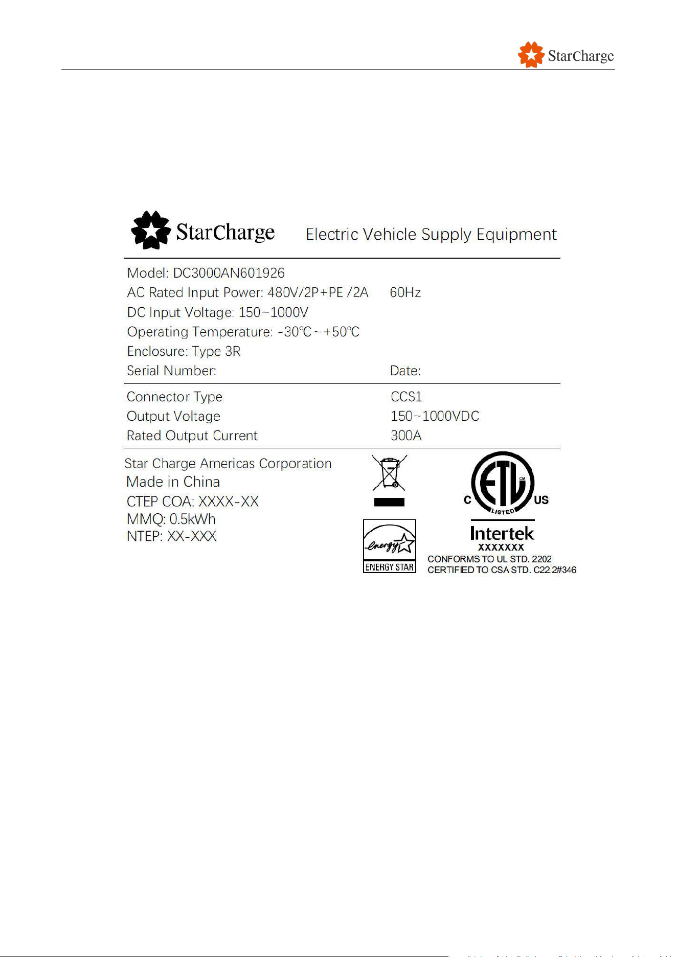
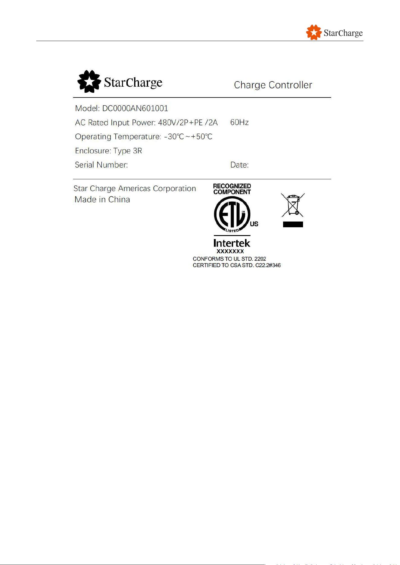
The following picture shows the nameplate format. The nameplate is located on the corresponding
devices.
Figure 3-1 Nameplate Format for Dispenser
V 1.0.0 Star
20
Figure 3-1 Nameplate Format for Charge Controller
V 1.0.0 Star
21
3.2 External view
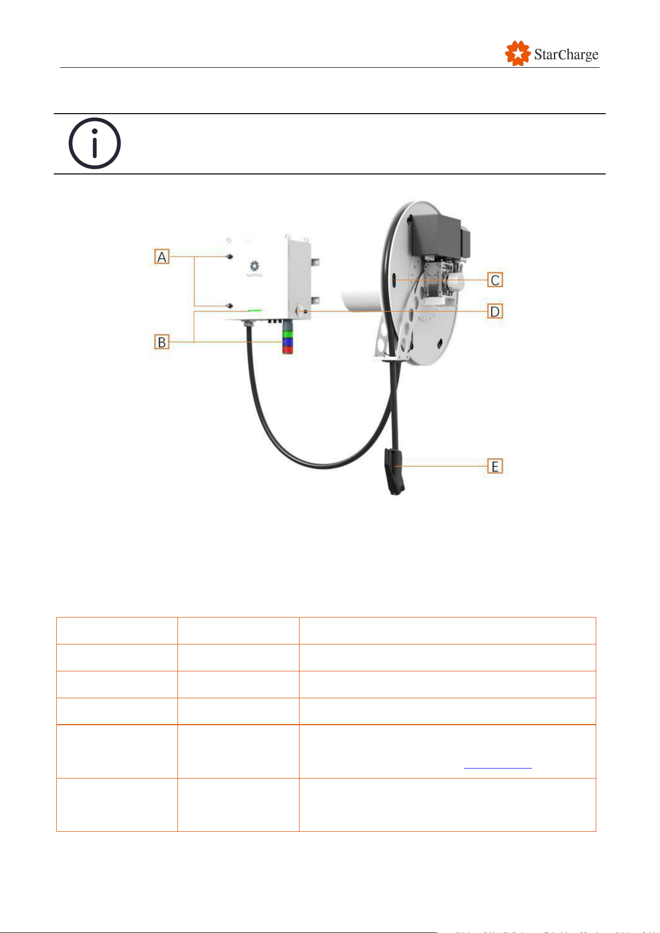
The figure below is for reference only, please refer to the actual product.
Figure 3-2 External view
A
Lock
D
Emergency button
B
Light
E
Charging connector
C
Charging reel
Part
Name
Description
A
Lock
To lock the door of the dispenser.
B
Light
To indicate the charging status of the dispenser.
C
Charging reel
Motor cable management system.
D
Emergency button
To immediately stop charging of the dispenser.
(For more information, refer to Chapter 2.9.)
E
Charging connector
To connect with EV to start charging.
Table 3-1 External component functions of the dispenser
V 1.0.0 Star
22
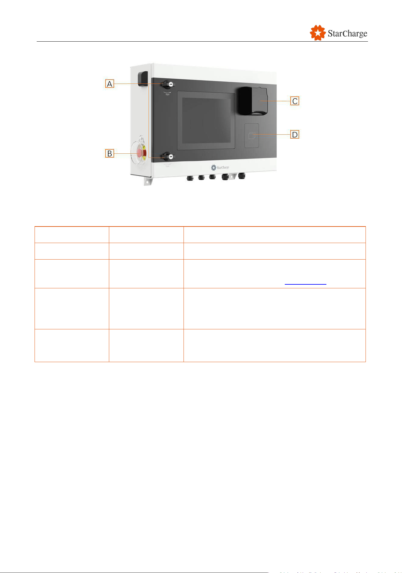
A
Lock
C
Payment terminal
B
Emergency button
D
RFID card reader
Part
Name
Description
A
Lock
To lock the door of the dispenser.
B
Emergency button
To immediately stop charging of the dispenser.
(For more information, refer to Chapter 2.9.)
C
Payment terminal
To read the information from a credit card to start or
stop the charging process, and to pay for the
charging session.
D
RFID card reader
To read the information from an RFID card to start or
stop the charging process.
Table 3-1 External component functions of the charge controller

V 1.0.0 Star
23
4 Transport, storage, and unpacking
4.1 Transport to the site
A transportation company is responsible for delivering the charging system to the site and moving
it to the designated location.
You are not allowed to transport or handle the EVSE unless you have proper authorization and
follow these safety measures.
Safety measures for handling EVSE equipment:
Check the weight of the EVSE on the Unpacking list. Make sure that the offloading
equipment you use can safely handle this weight.
Check that the pallet is not damaged. If the pallet is damaged, contact the site manager for
instructions on how to safely unload and move the EVSE.
Check that the work area is safe before handling the load (e.g., there should be no obstacles
in the unloading area, the flooring should be suitable, and there should be a safe path).
Make sure that the forklift or hoisting equipment you use for loading/unloading is suitable
and can move the EVSE safely. Also, check that the forks of the forklift can fully enter the
pallet to support the EVSE. Forklift operators must follow all local regulations.
Make sure that the area is not accessible to unauthorized personnel and that the personnel
involved in handling the equipment are fully aware of the safety measures to be applied
when handling the equipment. They should also stay a safe distance from moving
equipment.
All personnel involved in handling must wear the necessary personal protective equipment
(PPE) and follow all relevant safety measures for the work area.
4.2 Store the equipment
If you need to store the EVSE before installing it, refer to Chapter 6.1.4 for the environmental
specifications.
V 1.0.0 Star
24
4.3 Unpacking inspection
It is best to transport the EVSE in its original packaging and only unpack it when you reach your
destination. Once the EVSE arrives, the installation personnel shall do the following steps in the
presence of the owner:
Remove the packaging material.
Discard the packaging material (refer to Chapter 2.8) or keep the packaging material for
future use.
Carry out the unpacking inspection and meticulously fill in the unpacking record in Appendix
1.
If any problems are found in the process of unpacking and acceptance, make records and
wait for the negotiation between the owner and the supplier.
4.3.1 Unpacking list
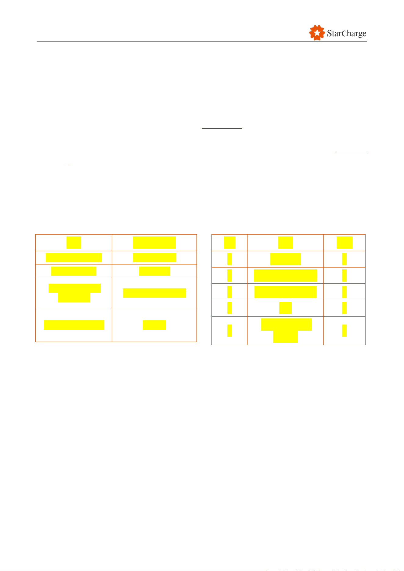
Packaging Specification Package Content
Table 4-1 Unpacking list
Item
Specification
Packing material
Wooden box
Configuration
Standard
Packaging size
(W×D×H)
860x655x750 mm
Packaging weight
92.5kg
No.
Item
QTY.
1
DC EVSE
1
2
Mounting template
1
3
Installation screws
5
4
Key
4
5
Wall mounting
bracket
1

V 1.0.0 Star
25
4.3.2 Inspection of unpacking
Unpacking inspection steps:
Check the number of items on the unpacking list and make sure that all of the equipment is
present.
Check the information on the equipment report to make sure that it is correct.
Check whether the attached documents are complete.
Check whether the spare parts and accessories are complete.
Check the delivery inspection report to make sure that it is present.
Check the appearance of the equipment to make sure that there are no dents, bumps,
stains, or other damage.
Check whether the charging cable on the dispenser is securely attached.

V 1.0.0 Star
26
5 Installation
5.1 Prerequisites
Before you start installing the charging system:
Make sure you have read and understood all the safety instructions (refer to Chapter 2).
Gather the tools you will need for the installation, based on the specific conditions of your
site (refer to Chapter 6.2.1).
Unpack the EVSE (refer to Chapter 4.3).
Review the current and distribution capacity specifications (refer to Chapter 6.1.2).
Check the installation environment (refer to Chapter 6.1.4).
Follow the regulations in your country to install and connect the EVSE.
Make sure that there is no voltage on the AC cables connected to the power cabinet during
the installation process.
Do the pre-installation check to make sure that the EVSE is ready to be installed (refer to
Appendix 2).
5.2 Site preparation
Before installing the charging system, you must make sure that there is enough space between the
power cabinet and the dispensers, between the EVSE and the surrounding obstacles, and between
the EVSE and the EV. This is to ensure proper airflow and to allow for any necessary service or
maintenance work.
V 1.0.0 Star
27
5.2.1 Space requirements between EVSE and obstacles
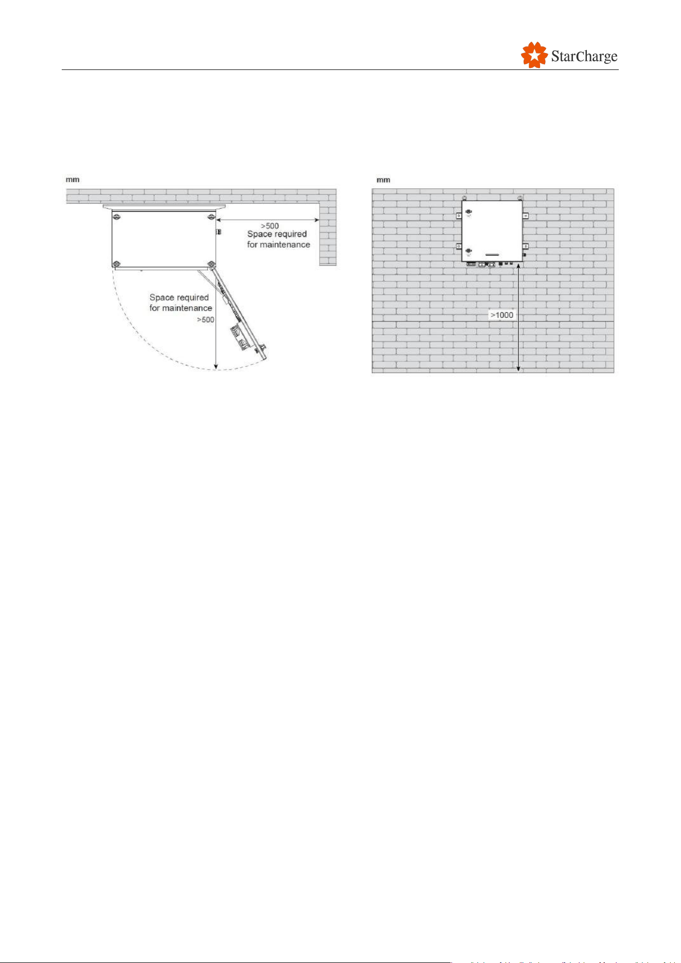
If the back or side of the EVSE you are installing is near a wall or other obstacle, you must leave
enough space for maintenance. See the diagram below for details.
Figure 5-1 Maintenance distance for the dispenser
Figure 5-1 Maintenance distance for the charge controller
Figure 5-1 Maintenance distance for the charging reel
V 1.0.0 Star
28
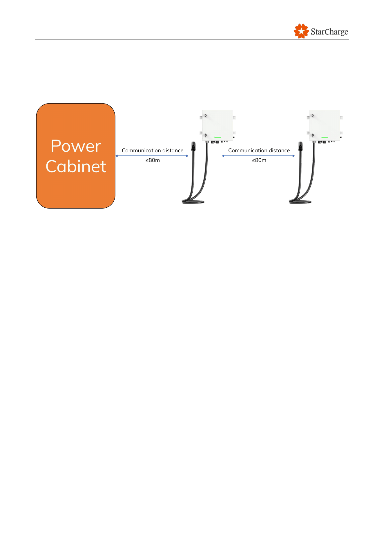
5.2.2 Communication distance requirements
It is recommended that the communication distance between the power cabinet and the dispenser,
as well as between dispensers shall not exceed 80m to avoid the risk of communication anomalies.
Figure 5-2 The network cable length
5.2.3 Airflow requirements
It is important to make sure that the equipment has enough air to circulate around it and that the air
inlet and outlet are not blocked. If the air cannot circulate properly, the internal components will not
be able to stay cool enough, and the power cabinet and dispenser will not work as well as they
should.
5.2.4 Canopy requirements
The installation of canopies at the charging station must comprehensively consider structural
safety, environmental adaptability, and user experience. Compliance with relevant international
and local standards and regulations is required.
Note: it is recommended to construct a canopy for the EVSE. The requirements below are for
reference only. The specific standards may vary depending on your local regulations.
5.2.4.1 General structural standards
Consider wind loads, snow loads, and seismic requirements based on the station's location to
ensure structural stability.
The canopy size must align with vehicle movement requirements, meeting minimum clearance
height standards (typically above 4.5 meters, can be adjusted based on operator’s usage
requirements).

V 1.0.0 Star
29
The reference standards are as follows:
○ ISO 3010: Principles for seismic design of buildings.
○ EN 1991 (Eurocode 1): Structural load standards, including snow, wind, and seismic loads.
○ EN 1993 (Eurocode 3): Steel structure design standards.
○ EN 1999 (Eurocode 9): Aluminum structure design standards.
○ ASCE 7: Minimum design loads for buildings and other structures, including wind, snow,
and seismic considerations.
5.2.4.2 Environmental and durability standards
Canopy materials should be high-strength, corrosion-resistant, and UV-resistant to ensure
longevity.
Use environmentally friendly materials to minimize ecological impact.
Material Performance and Environmental Adaptability:
○ ISO 12944: Corrosion protection of coating systems for outdoor metal structures.
○ ISO 9223: Classification and design standards for atmospheric corrosion resistance.
○ ISO 14001: Environmental management systems.
○ ASTM G154: UV aging tests to assess material durability.
5.2.4.3 Fire safety and emergency evacuation
Construct canopies using fire-resistant materials, especially for covered areas.
Provide clear emergency evacuation signs, particularly in large stations.
The reference standards are as follows:
○ ISO 834: Fire resistance tests for building components.
○ NFPA 5000: Building construction and safety code.
○ EN 13501: Fire classification for building materials and components.
5.2.4.4 User experience and accessibility design
Provide adequate lighting (e.g., LED lights) to meet safety and operational needs at night.
Canopy design should consider pedestrian and vehicle flow to avoid congestion or interference.
The reference standards are as follows:
○ ISO 2575: Standards for road vehicle symbols and information, applicable to charging
station signage.
○ EN 81-70: Accessibility design to ensure safe use by wheelchair users.
○ ADA (Americans with Disabilities Act): Accessibility Guidelines for Buildings and Facilities.
V 1.0.0 Star
30
5.3 Cable preparation
Once the installation site is ready, check the cables according to “Wiring Guide”.
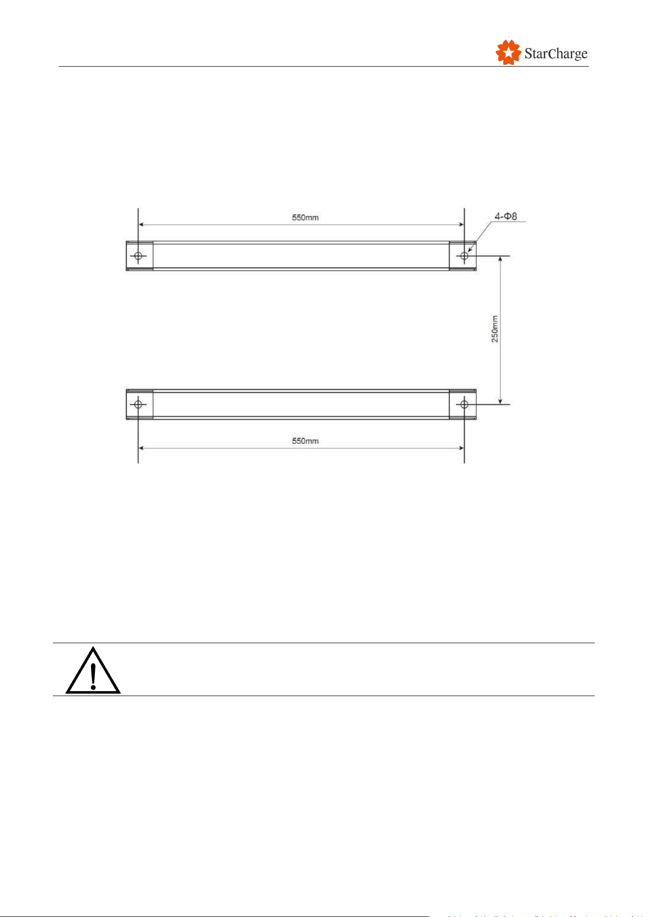
5.4 Site preparation
Make the installation holes on the gantry, according to the template provided with the dispenser.
Figure 5-4 Mounting position
5.5 Grounding/insulation resistance check
Verify that the grounding resistance test report to confirm that the grounding grid’s resistance
created on-site is compliant with local regulations.
Verify that the insulation resistance test report to confirm that the cable’s insulation resistance
is ≥1MΩ.
The requirements above are the minimum requirements for installing an EVSE. The
specific standards may vary depending on your local regulations.
V 1.0.0 Star
31
5.6 Dispenser installation
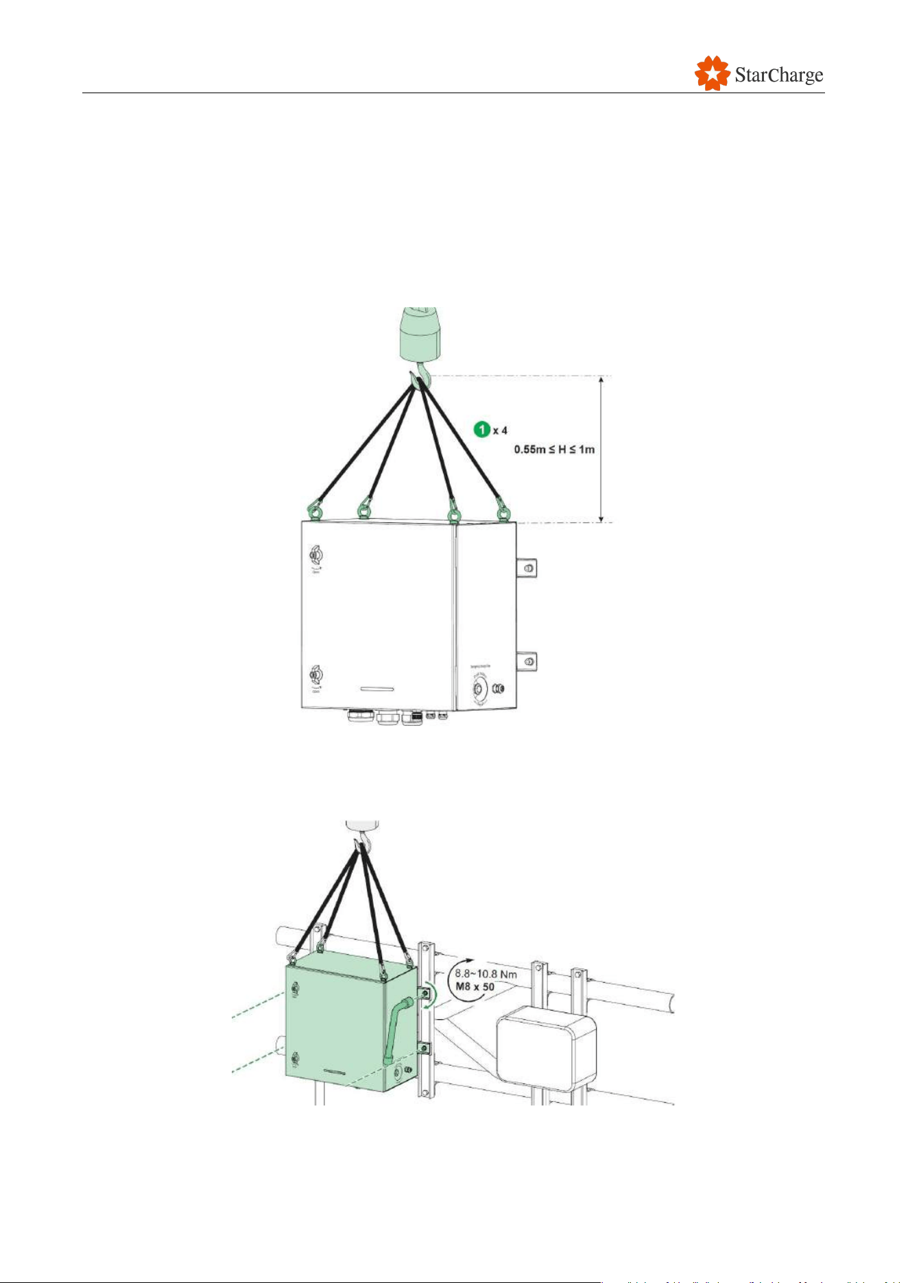
Hoisting:
Move the dispenser pallet close to the installation site.
Attach firmly the hoisting ropes to the dispenser lugs while still on the bottom pallet.
Prepare and secure in place the manual hoist.
Ensure the gantry is prepared correctly.
Prepare to hoist the dispenser.
Figure 5-5 Hoisting
Fixing:
Hoist the dispenser with the manual hoist slightly near to gantry.
Mount the dispenser using the provided M8×50 screws on the holes on the gantry.
Figure 5-6 Gantry mounted fixing
V 1.0.0 Star
32
5.7 Charging reel installation
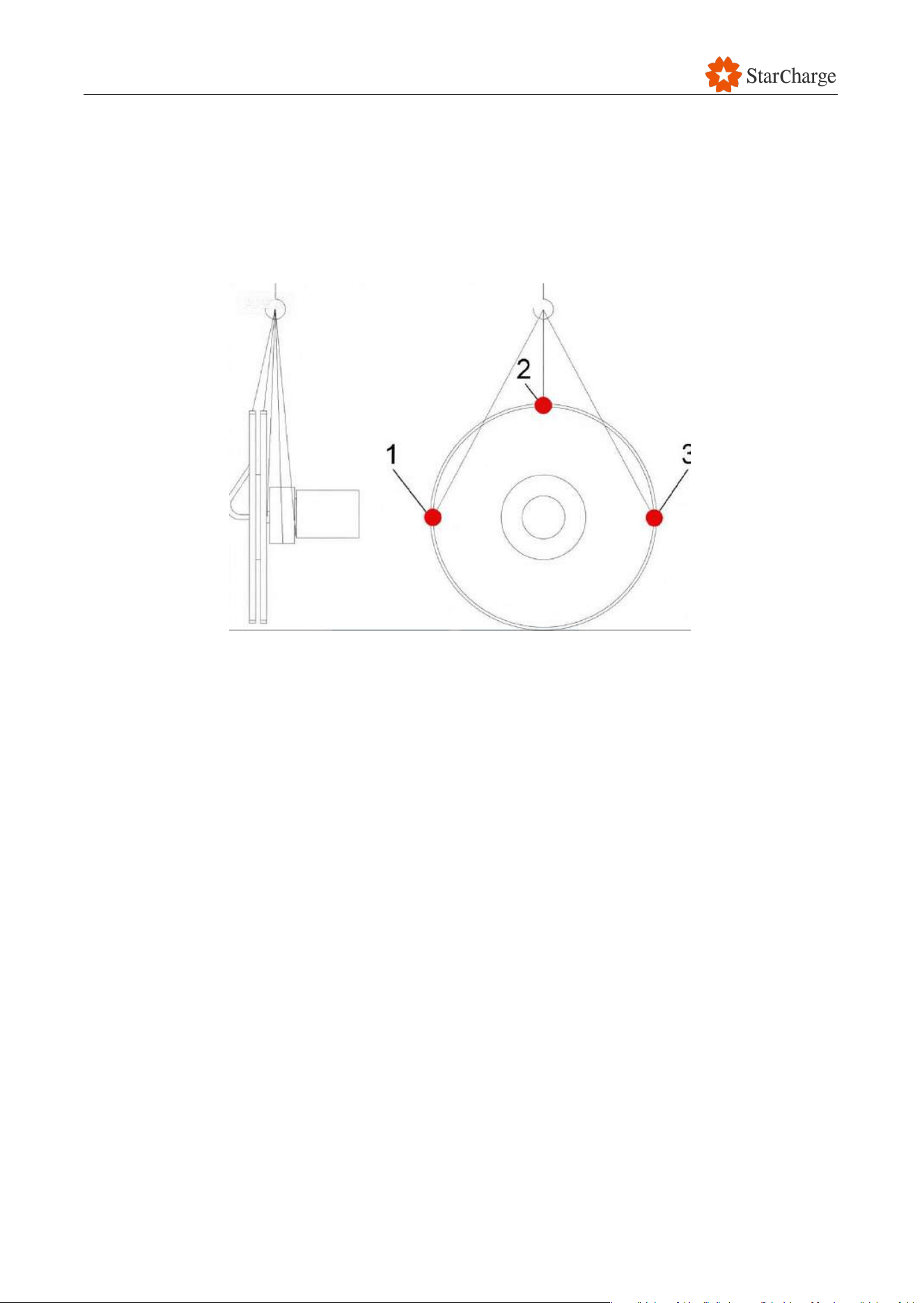
Hoisting: Before attaching the belts to the reelbody(cf.drawing,items1,2and3)it has to be ensured
that the reel spokes cannot be compressed during lifting. Should there not beany
transportationlocks at the sepositions you will have to insert square-shaped timbers there and
attach themby means of adhesive tape.
Figure 5-7 Transport–Charging cable reel (illustrated example)
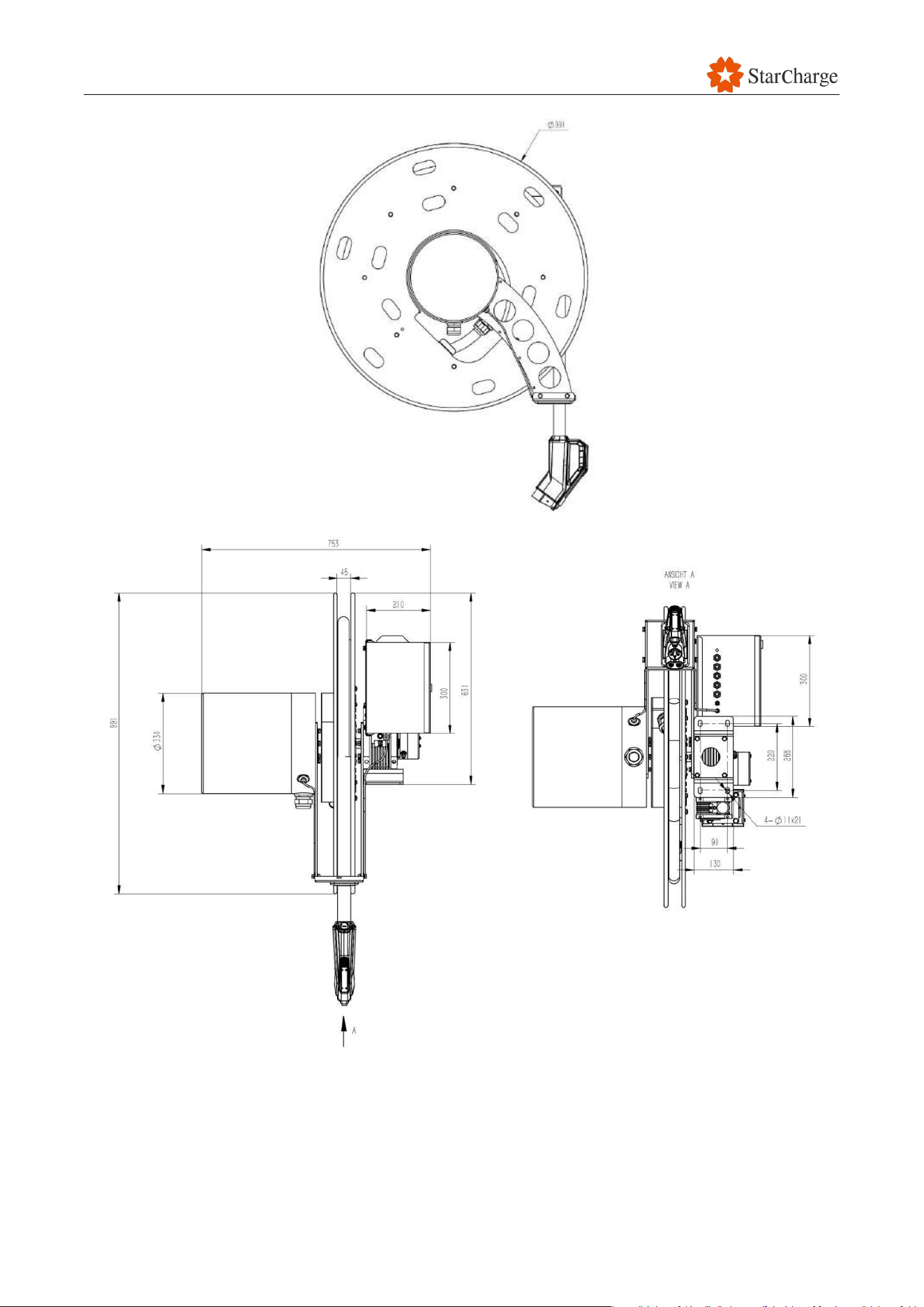
Fixing:Prior to installation please check the foundation on which the Charging cable reel
shall be installed.Dimension sand attachment hole shave to correspond to the foundation plan.
The dimensions of the foundation for the Charging cable reelareindicated
on thedimensional drawing of the Charging cable reelwhich youhave in
hand.
V 1.0.0 Star
33
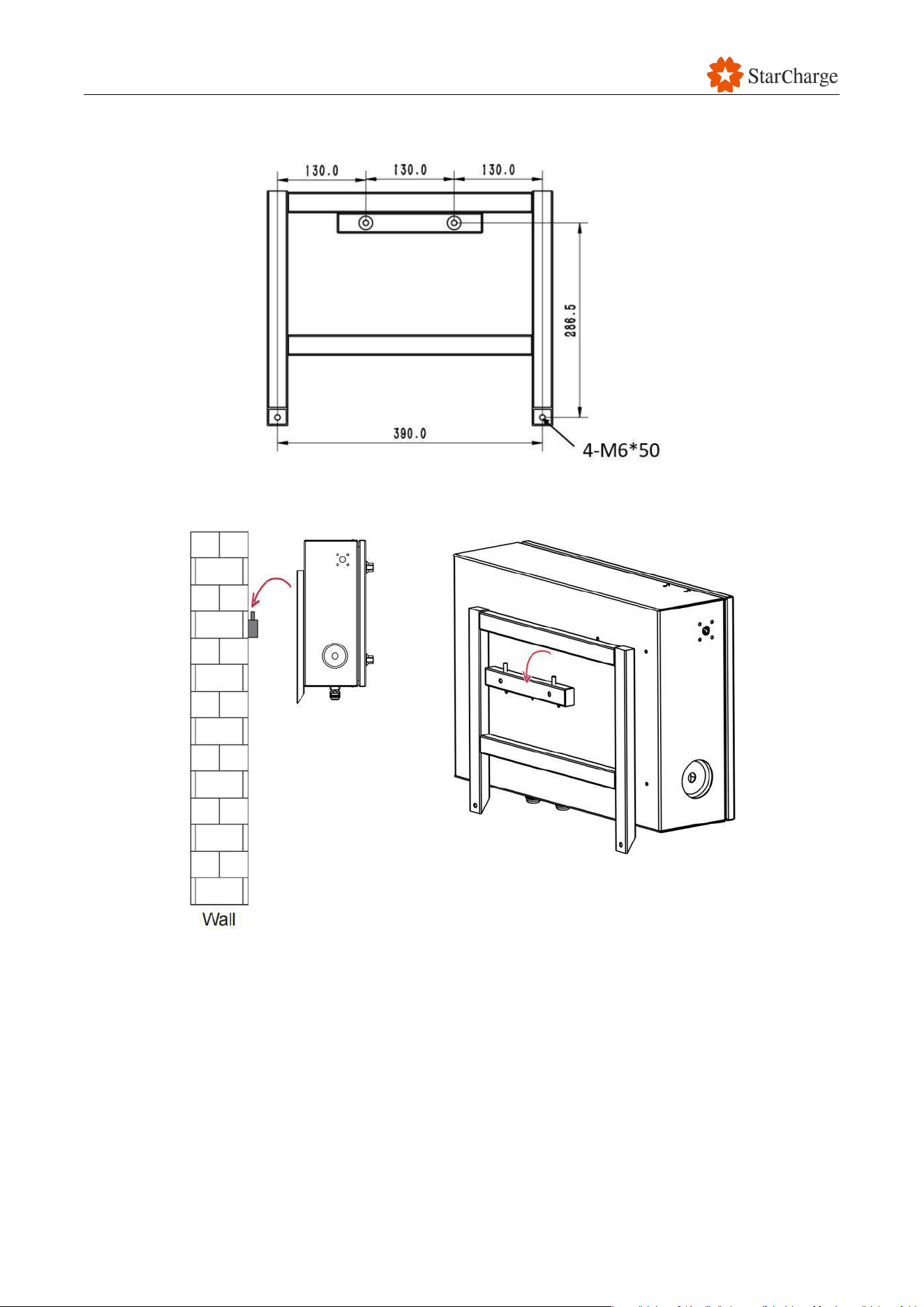
Figure 5-8 Installation of Charging cable reel
V 1.0.0 Star
34
5.8 Charge controller installation
Figure 5-9 Mounting position of Charge controller installation
Figure 5-10 Installation of Charge controller installation
5.9 Electrical installation
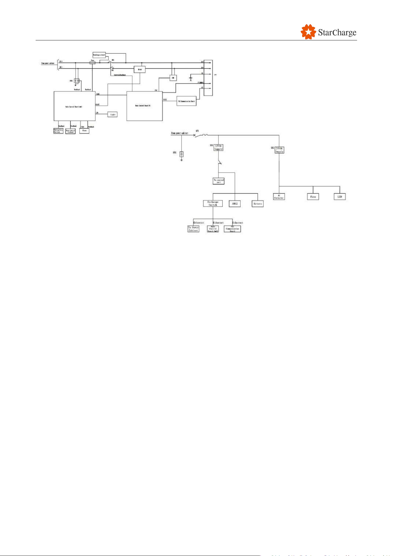
5.9.1 Electrical schematic diagram
The following figure shows the schematic of the dispenser.
V 1.0.0 Star
35
Figure 5-8 Electric schematic of the dispenser
V 1.0.0 Star
36
5.9.2 Cable wiring
During wiring and connections, care should be taken to avoid scratching or
damaging the cable insulation to prevent short circuits.
Follow the steps below to do the cable wiring.
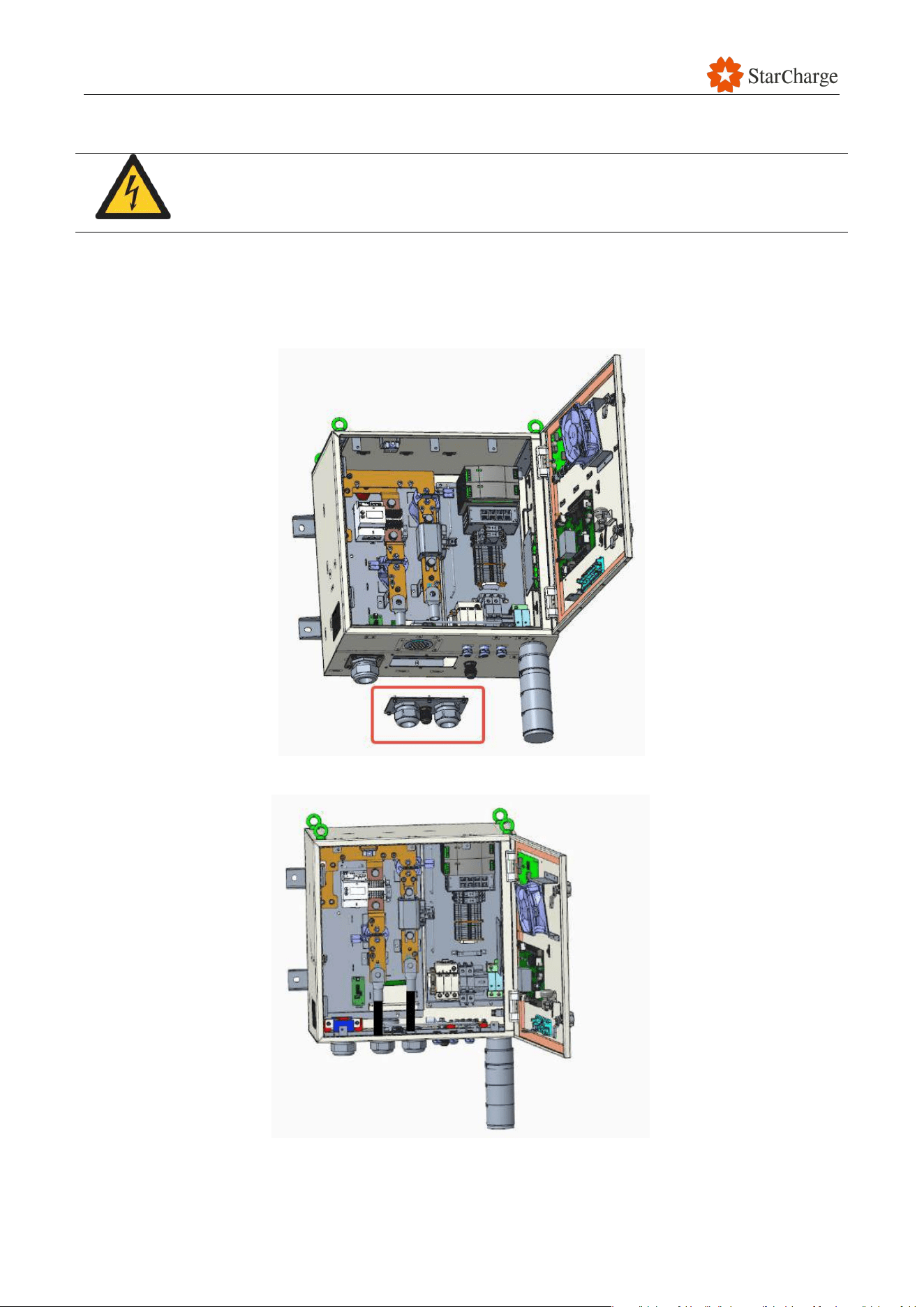
5.9.2.1 Dispenser Cable wiring
1.拆下底部进线钣金,并打孔安装与 DC+,DC-与 PE 线缆对应的格兰头
2. DC+与 DC-线缆穿过格兰头并压接铜鼻子,铜鼻子以 50Nm 的扭矩紧固。
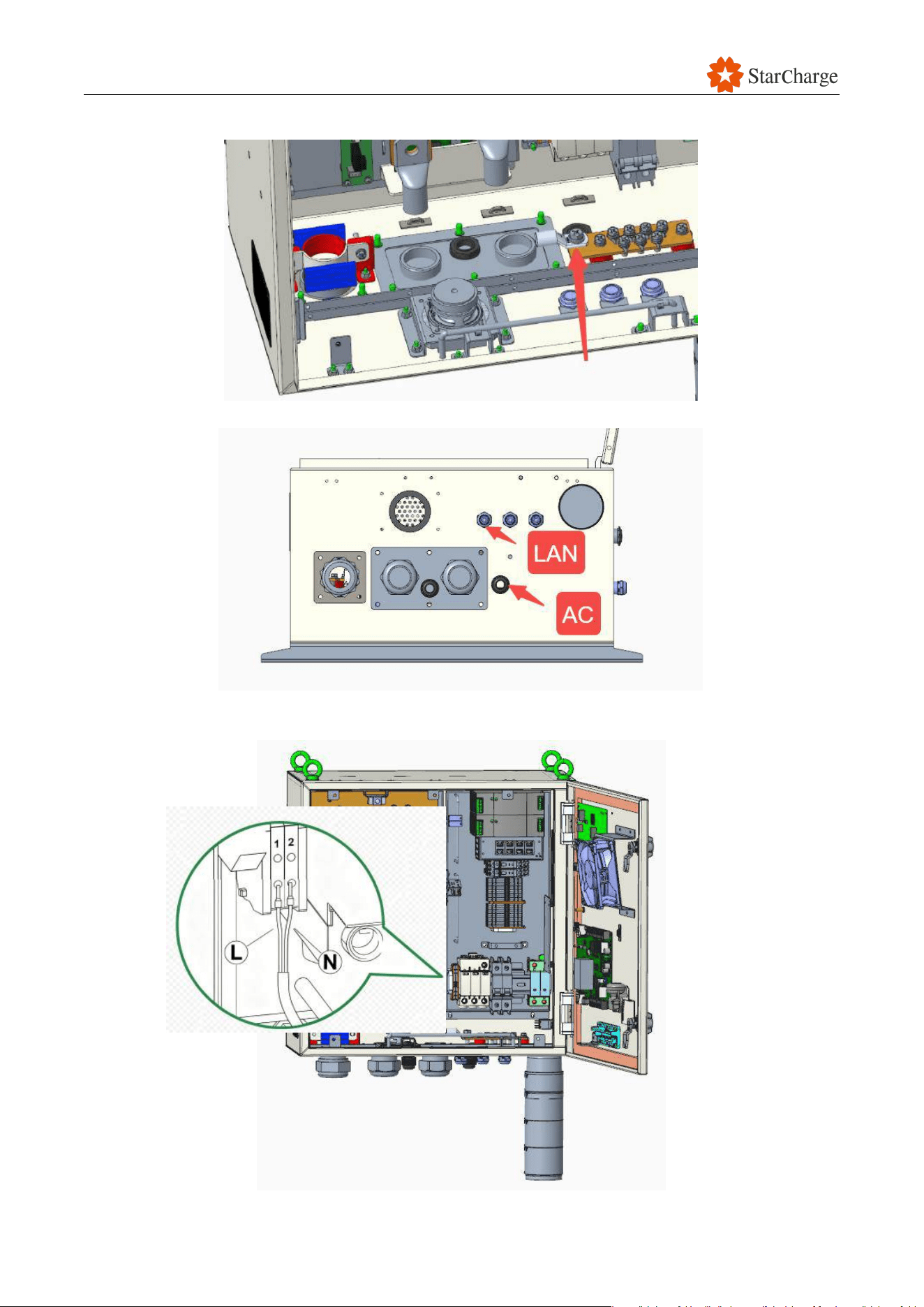
V 1.0.0 Star
37
3.PE 线穿过格兰头并压接铜鼻子,铜鼻子以 10Nm 的扭矩紧固
4.交流进线和网线穿过终端自带的格兰头,并压接针形端子和水晶头
5.交流进线接法如下
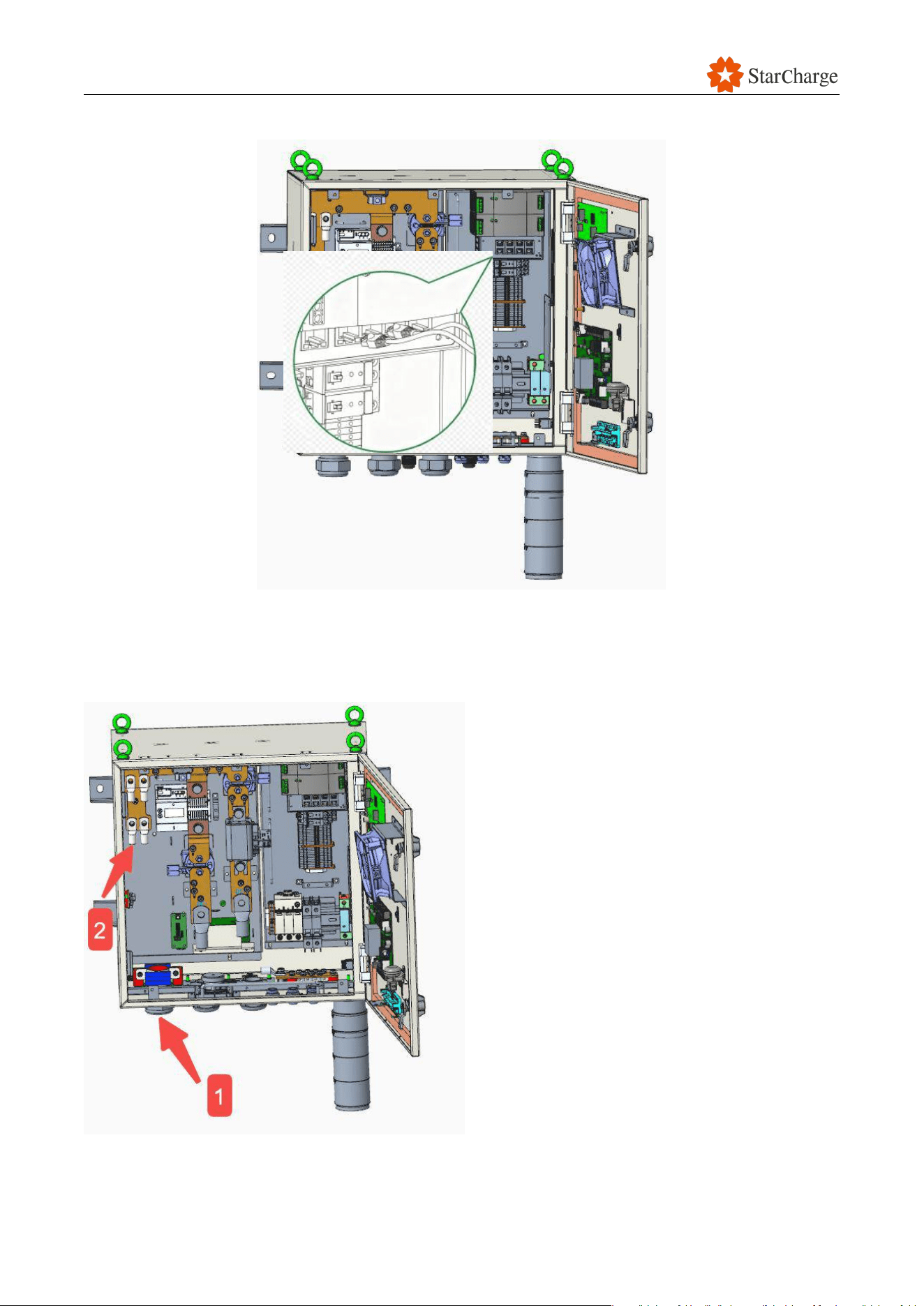
V 1.0.0 Star
38
6.网线进线接法如下,共两根,一根为客户进线,一根为卷线盘网线进线
7. 来自卷线盘的充电枪线接法如下
1. 穿过最左侧格兰头
2. 2.将 4 个端子以 10Nm 扭矩固定在铜排上,注意区分正负极
3. 插接枪线信号线连接器
V 1.0.0 Star
39
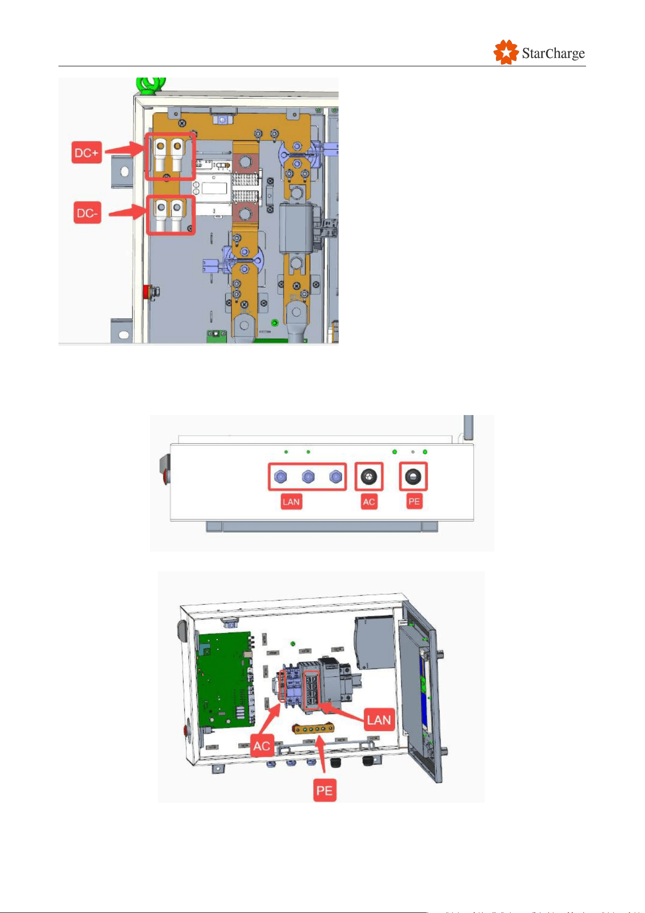
5.9.2.2 Dispenser Cable wiring
1.底部网线 AC 线和 PE 线先穿过格兰头进线,后压端子或水晶头
2.将网线 AC 线和 PE 线接线到对应位置,P 线铜鼻子以 10Nm 的扭矩紧固

V 1.0.0 Star
40
5.10 Check after installation
5.10.1 Installation and wiring check
Before the EVSE is turned on, only authorized personnel should inspect it. This section describes
what to look for when inspecting the EVSE and its mounting:
The EVSE should be clean and tidy, without any dents or damage. It should also be firmly
attached to the base and not wobbly.
The EVSE should be installed in the correct orientation, and all parts should be present. The
installation should also be level.
The cables should be laid and connected correctly.
The insulation on the cables should not be scratched or damaged.
The power cable terminals should be tight, and the communication cable terminals should
be correct and not loose.
There should be no hanging cables, and the bending radius of the cables should meet the
requirements.
The ground wire should be connected to the grounding grid for the device.
5.10.2 Check before power on the EVSE
Short circuit check: Make sure there is no short circuit between the three phase wires, the
neutral wire, and the ground wire in the power cable of the low-voltage distribution cabinet
that is connected to the EVSE.
Power voltage check: Make sure the power voltage at the top of the MCCB in the low-voltage
distribution cabinet is normal. There should be no problems such as missing phases,
overvoltage, undervoltage, or incorrect phase sequence.

V 1.0.0 Star
41
5.10.3 Check on power-on
The EVSE can only be turned on after all the wiring is complete and correct. Here are the steps to
turn on the EVSE:
(1) Close all MCCBs in the upstream power distribution cabinet.
(2) Measure whether the voltage of the output terminal of the MCCBs in the power distribution
cabinet is 400 Vac (±10%).
(3) Measure whether the voltage of the inlet AC copper busbars in the EVSE are approximately
400 Vac (±10%).
(4) If the above conditions are met, power on the EVSE.
5.11 Completion information
Number
Name
Number of pages
Document Necessity
1
Unpacking record sheet
1
Required
2
Pre-installation checklist
1
Required
3
Post-installation checklist
1
Required
Table 5-1 Completion information

V 1.0.0 Star
42
5.12 Appendix
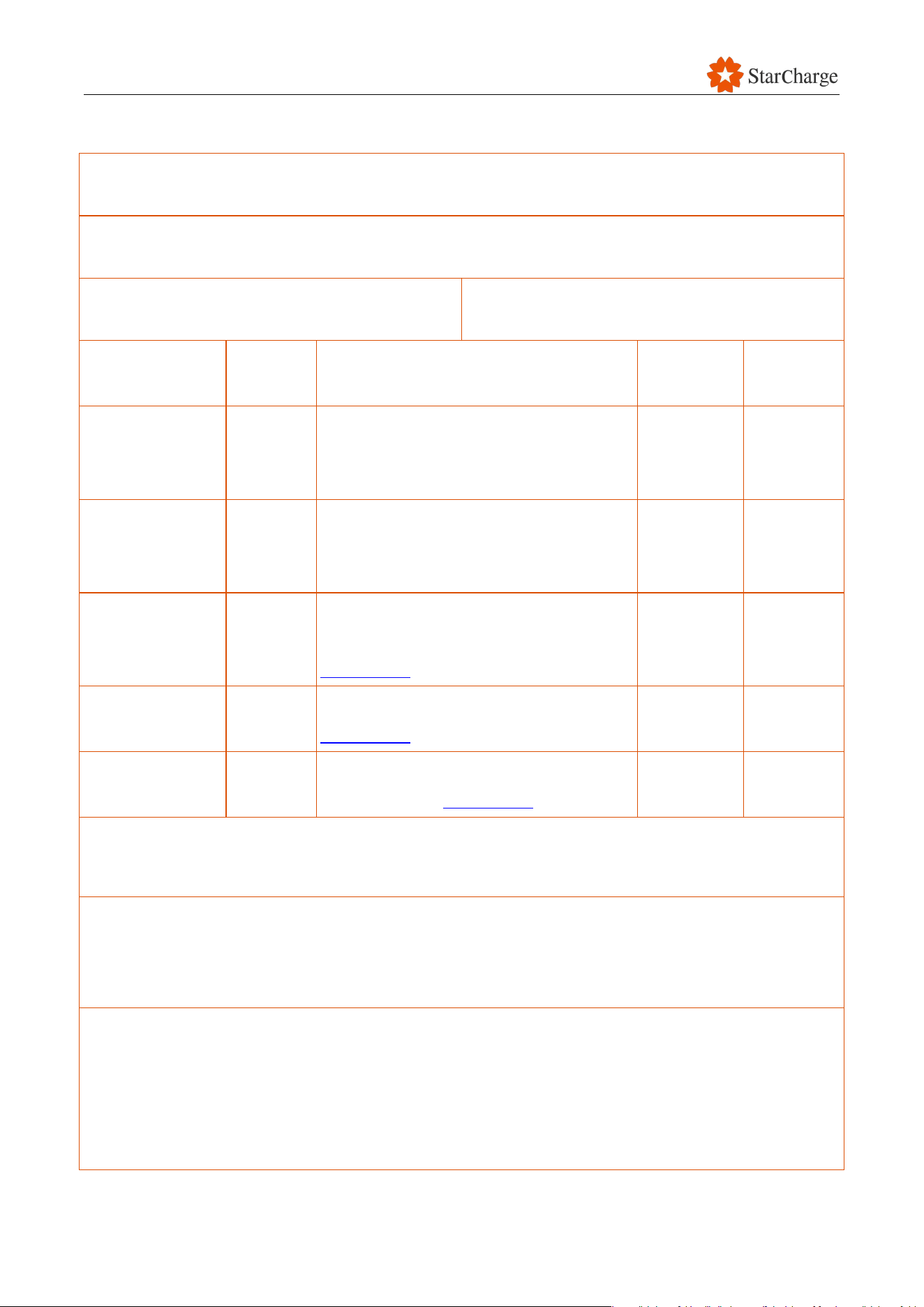
Appendix 1 Unpacking Record Sheet
Unpacking Record Sheet
Name of owner
Unpacking
date
No.
Case
Name of goods
Quantity
Acceptance
Notes
Unpacking
conclusion
Signature
block
Installation
unit
Owner unit
V 1.0.0 Star
43
Appendix 2 Pre-installation Checklist
Pre-installation Checklist
Project name:
Civil construction unit:
Equipment installation unit:
Sub-project
SN
Main acceptance items
Acceptance
record
Treatment
measures
Installation plan
1
Whether the on-site equipment
installation plan complies with the
construction plan design drawings.
Distribution
cabinet MCCB
1
Meet the equipment installation
requirements in “Installation Manual” for
power cabinet.
Maintenance
distance
1
The maintenance distance meets the
equipment spacing requirements in
Chapter 5.2.
Cable type
1
The cable meets the requirements in
Chapter 5.3.
Concrete
foundation
1
The concrete foundation meets the
requirements in Chapter 5.4.
In conclusion:
Note:
(1) In the acceptance record, fill in "√" or "×" according to the on-site situation.
(2) At the conclusion, fill in "qualified" or "need to rectify" according to the on-site situation.
Signature of person in charge of inspection: ___________________
Date:

V 1.0.0 Star
44
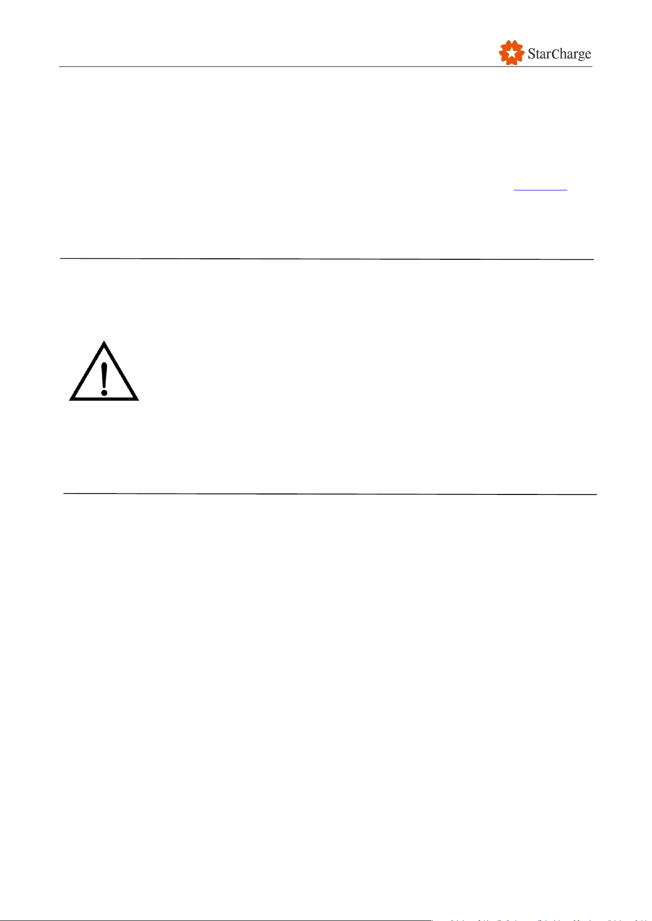
Appendix 3 Post-installation Checklist
Post-installation Checklist
No.
Checking items
Checking result (Y/N)
Note
1
Installation levelness is qualified
2
The appearance is clean and tidy without
bumps or damages
3
All the parts /screws/bolts are fixed firmly
without looseness and no parts missing
4
No insulating layer of cable is scratched or
damaged
5
The phase sequence of the power cable wiring
is correct
6
The wiring terminals and screws are tightened
without looseness
7
The upstream main circuit breakers (MCCBs)
meet the requirements
8
No abnormality in the upstream power grid
voltage
V 1.0.0 Star
45
6 Commissioning
6.1 Prerequisites
Before you start commissioning the charging System:
● Make sure you have read and understood all the safety instructions (refer to Chapter 2).
● Please prepare the debugging tools as per the appendix 4 of this chapter.
● Follow each step carefully while wearing the right safety gear, such as insulated shoes
and gloves.
● Only authorized personnel should commission the EVSE, in accordance with
local laws and regulations. StarCharge is not responsible for any losses
caused by unauthorized commissioning by third-party personnel.
● Commissioning must be done carefully following the procedures. If any
operation cannot be completed, stop until the cause is found and fixed.
● Do not commission the EVSE in severe weather conditions such as rain, snow,
or sandstorms.
● During commissioning, the personnel must not leave the site while the door is
open. The personnel must warn other people of the danger and prevent third
parties from being curious and accidentally getting electrocuted. When
leaving the site, make sure that all charger doors are closed and locked.
V 1.0.0 Star
46
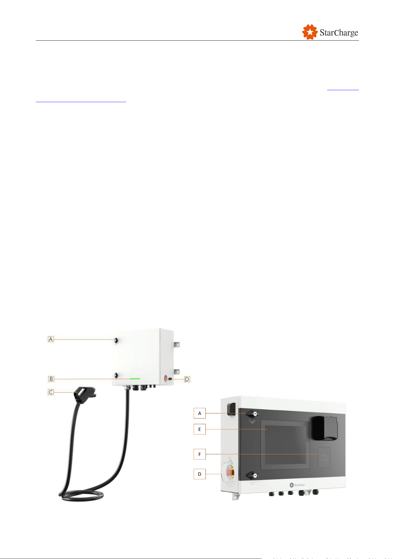
6.2 Commissioning flowchart
The commissioning flowchart of this EVSE is as follows:
Figure 6-1 Commissioning flowchart
V 1.0.0 Star
47
6.3 Installation recheck
Before commissioning the EVSE, make sure the following meet the installation requirements.
Complete all the checkpoints and record any items that do not meet the requirements in Appendix
1 Post-installation Checklist.
● Check the equipment spacing (Refer to chapter 5.2 of the Installation Manual).
● Check the cement foundation (Refer to chapter 5.4 of the Installation Manual).
● Check the input voltage and current, and the distribution capacity (Refer to chapter 6.1 of
the Installation Manual).
● Check the cables and cable wiring (Refer to chapter 2 of the Wiring Guide Manual).
6.4 EVSE power on and check
6.4.1 Pre-power-on check
6.4.1.1 Visual check
Complete all the checkpoints and record all the items that do not meet the requirements.
● Appearance:
○ Check whether the enclosure of the EVSE is clean and if there is any paint peeling,
scratches, deformation, dents, cracks, or gaps.
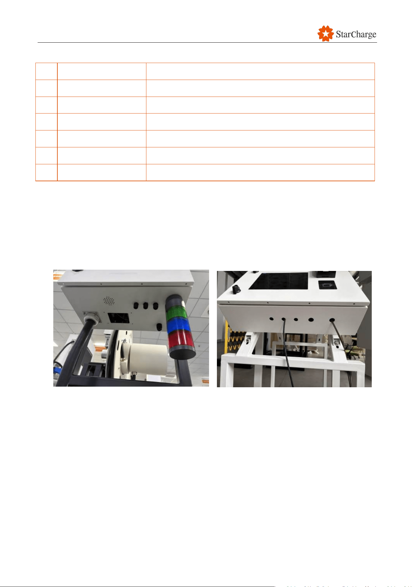
○ Check whether the Lock (A), the LED light (B), Charging connector(C), Emergency Button(D),
HMI(E), Card reader(F) are free of cracks and the frames are sealed without gaps.
V 1.0.0 Star
48
Figure 6-2 Appearance check
Part
Name
Description
A
Lock
To lock the door of the dispenser or the control box.
B
LED light
To indicate the charging status of the dispenser.
C
Charging connector
To charging the EV.
D
Emergency stop button
To immediately stop charging of the dispenser.
E
HMI
To display the charging information.
F
Card reader
To identify the card.
● Nameplate: Check whether the nameplate is clear and intact, and the safety symbols are
properly attached.
● Documents: Check whether the configuration information of the on-site EVSE conforms to the
requirements of the contract, and if the accompanying documents are complete.
● Sealing:
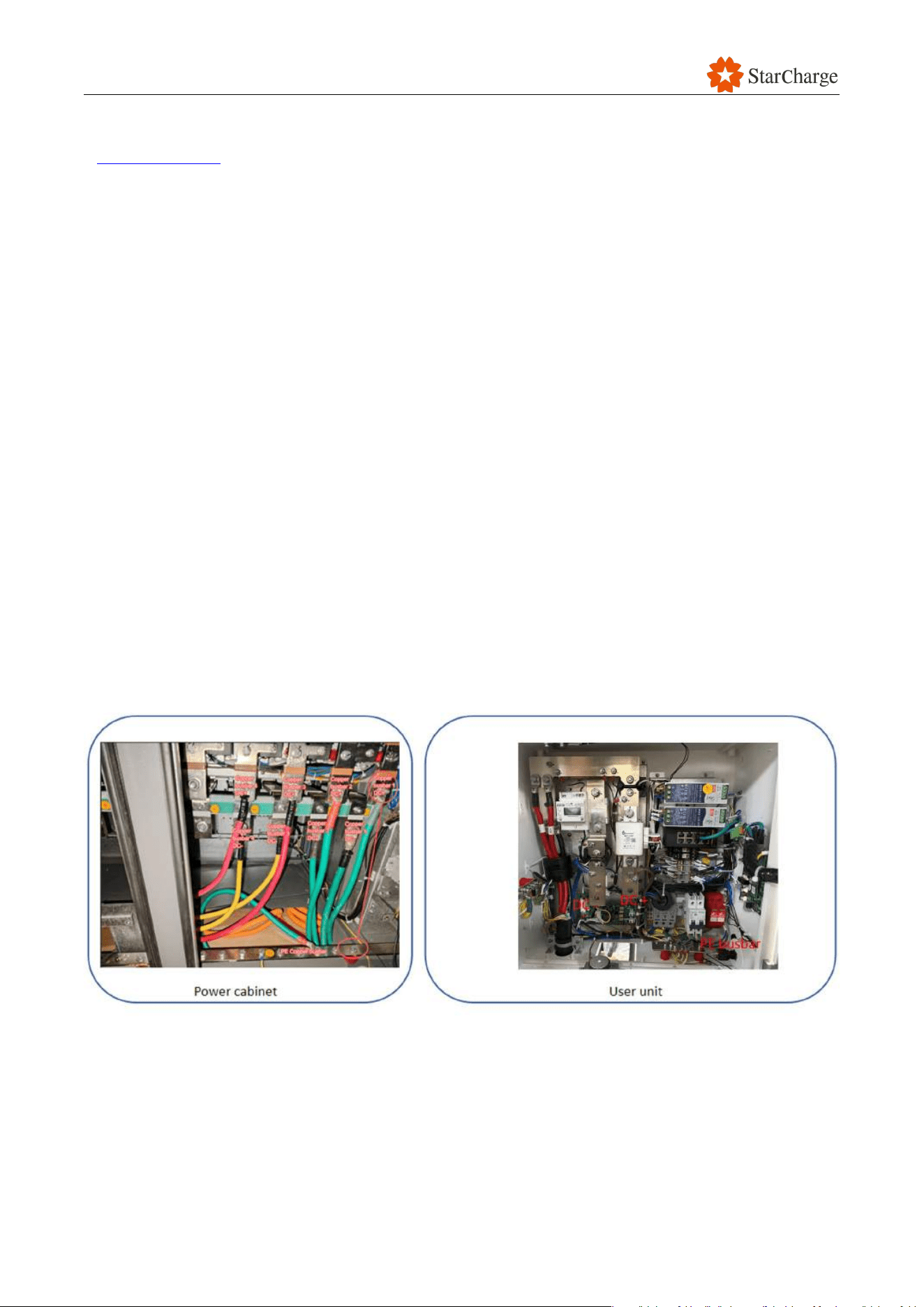
○ Check whether the inlet hole of the Triton base is covered with sealant or sealing board.
Figure 6-3 Sealing
○ Check whether the rubber seals of the door frame are free of falling off, deformation, and
damage, and if the rubber seals can fully fit the door panel after closing.
○ Check whether the glands of the charging cables at the top of the user unit are sealed and
not loose.
● Protection film: Check whether all the protective films of the EVSE have been removed, such as
the films covering safety symbols, the touchscreen, the energy meter, and payment devices.
6.4.1.2 Environmental condition check
Refer to Chapter 6.1.4 of the Installation Manual for the environmental conditions that this EVSE
V 1.0.0 Star
49
can operate in. Complete the checkpoints and record any items that do not meet the requirements
in Appendix 3-3.2.
6.4.1.3 Internal cable inspection
In order to ensure the successful debugging and normal operation of the system, it is necessary to
conduct a performance check of the cables before the debugging process begins.
● The inspection of the DC cable (Insulation Performance).
● The Inspection of the DC Cable (Verification of DC Cable Polarity).
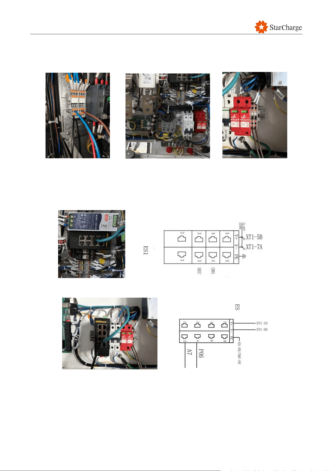
Check the correctness of the polarity connection of the DC cables from the power cabinet to the
user unit.
(1) Connect the DC positive pole of copper connector 1 in the power cabinet to PE copper busbar
with a wire.
(2) Test the continuity between the DC positive input cable of connector A and PE copper busbar
inside dispenser 1.
(3) It is normal if the DC positive input cable of connector A to the PE copper connector inside
dispenser 1 is continuous. If the connection is not continuous on the dispenser side, it indicates
an abnormal wiring. Please verify the DC cable.
Use the same method to check the correctness connection of each copper connector between the
power cabinet and the dispenser.
Figure 6-4 Verification of DC Cables
V 1.0.0 Star
50
● 480V AC cables check
Check whether the 480VAC cables inside the power cabinet and the user unit are properly
connected and securely fastened.
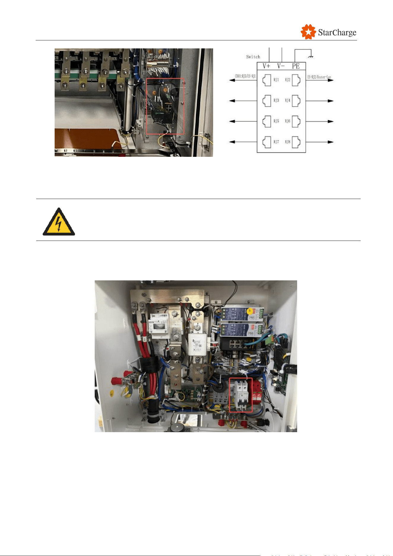
Figure 6-5 Terminal inside power cabinet and user unit and control box
● Internet cable check
Check if power cabinet, user unit, control box and CMS Internet cables are properly inserted and
Internet cables are workable. (Control box will be connected to one of the user unit based on real
situation. Each CMS will be connected to the corresponding user unit)
Figure 6-6-1 Switch inside user unit
Figure 6-6-2 Switch inside control box
V 1.0.0 Star
51
Figure 6-7 Switch inside power cabinet
6.4.2 EVSE Power on
You must follow these steps carefully to turn on the EVSE. Be careful of electric
shock and wear protective gloves and shoes.
(1) Turn on the MCCBs in the power distribution cabinet that provide power to the power cabinet.
(2) Turn on the MCCBs in the power cabinet that provide power to the user unit.
(3) Turn on the RCCB inside EVSE.
Figure 6-8-1 Turn on the RCCB inside user units
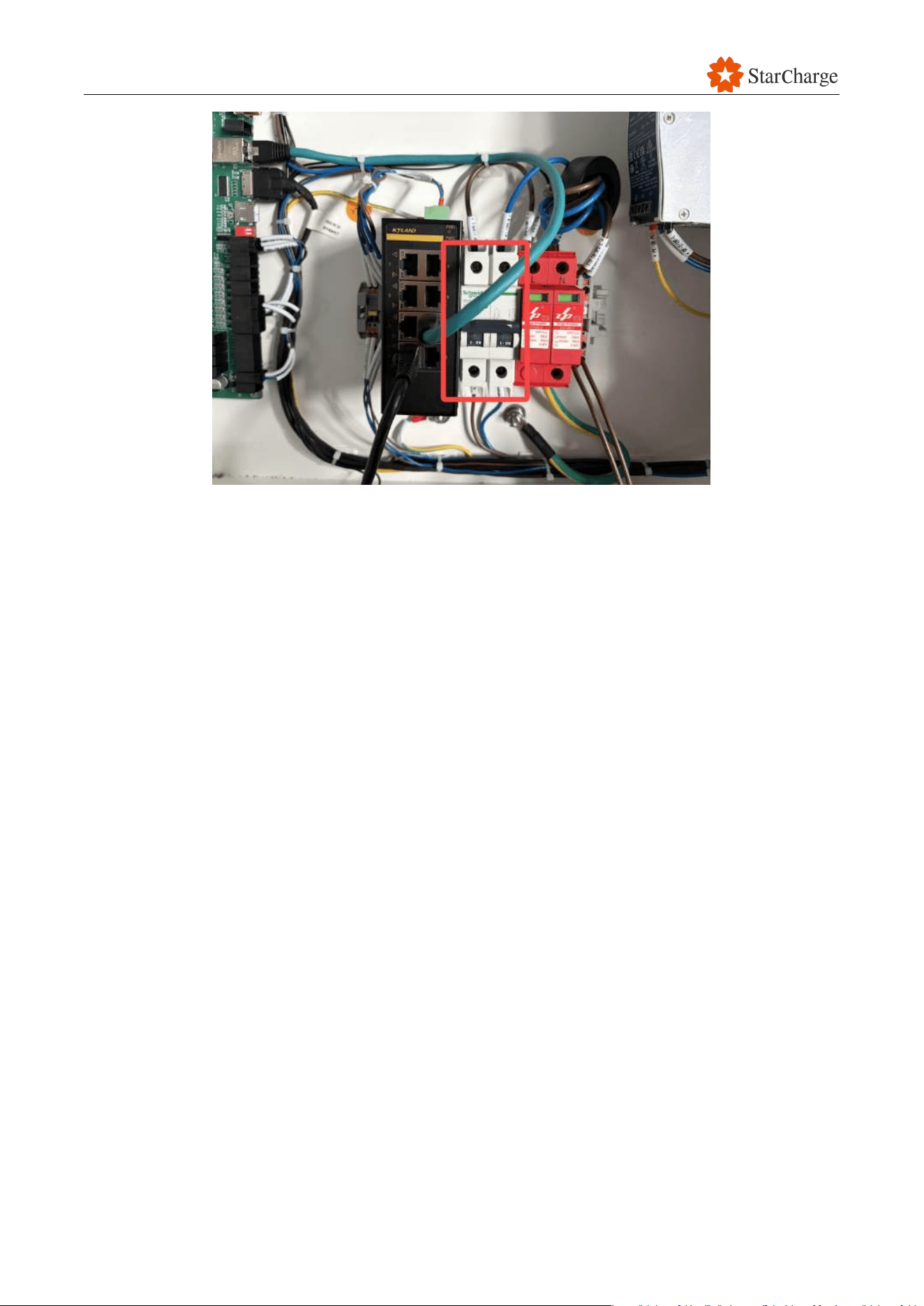
V 1.0.0 Star
52
Figure 6-8-2 Turn on the RCCB inside control box
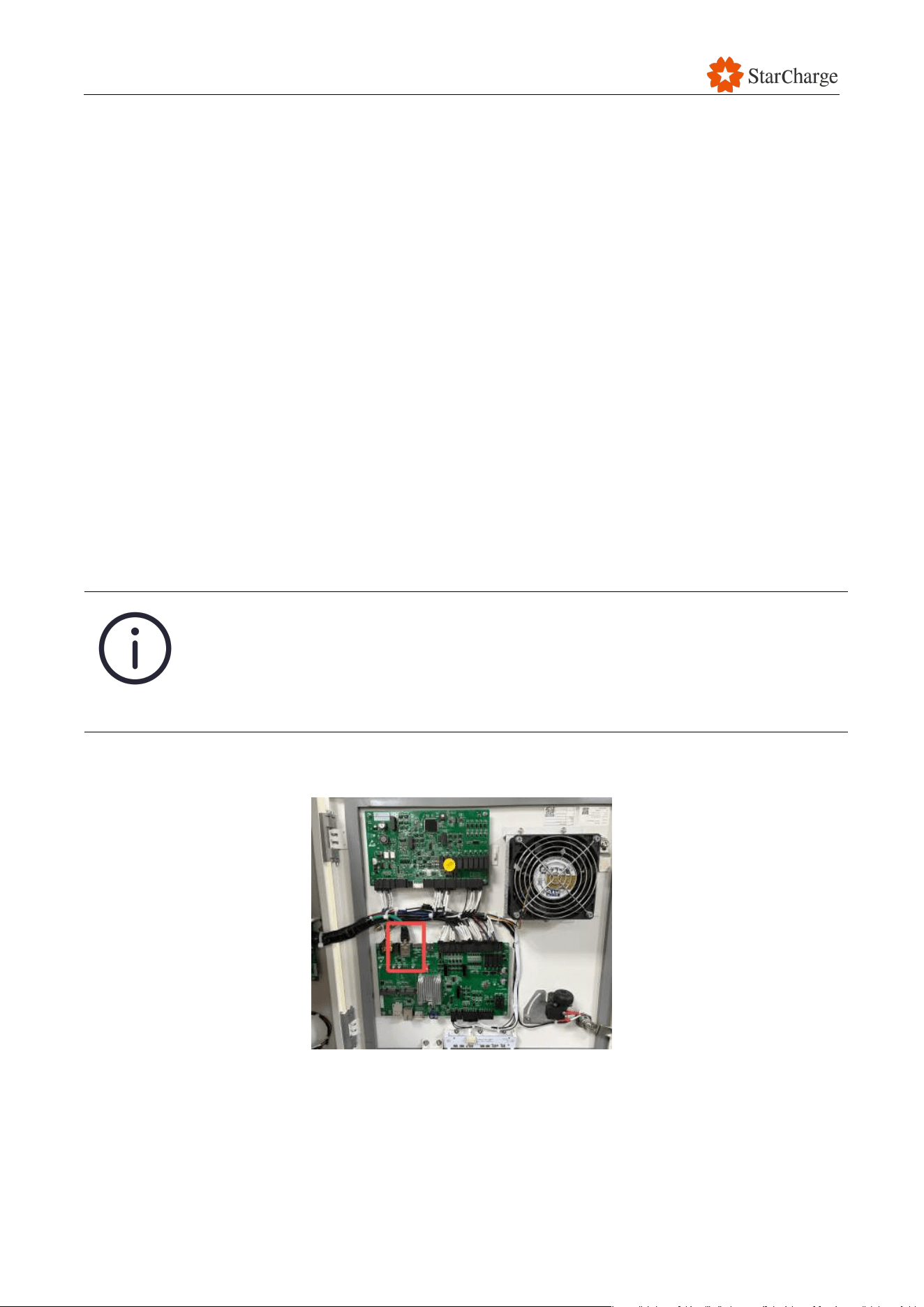
V 1.0.0 Star
53
6.4.3 Recheck after power on
Check whether the following hardware functions meet the requirements.
● Voltage: Check that the output voltage of the main breaker inside the user unit is correct and
that there are no faults, such as phase loss, overvoltage, undervoltage, or wrong phase
sequence.
● Touchscreen: Check that the touchscreen displays normally, without any dead pixels, and that
the words are clearly displayed. Make sure that the touchscreen is operating well with clear
user interface (UI).
● LED status indicator: Check that the LED status indicator on the user unit functions well
according to the design requirements.
● Power supply unit (PSU): The PSU can provide a stable voltage. Use an electrical multimeter to
check that the output voltage of the PSU inside the user unit meets the requirements.
● Residual current circuit breaker with overcurrent protection device (RCBO): Press the "Test"
button on the RCBO to check whether the device trips.
6.5 Laptop configuration
Only when the parameters settings are correctly completed after power on, the
split system can communicate normally. Every part has the unique IP address.
Therefore, there may be conflicting mailing IP addresses for individual parts
before all the RealGun ID parameters are set, parameters need to be individually
set for each user unit and the power cabinet.
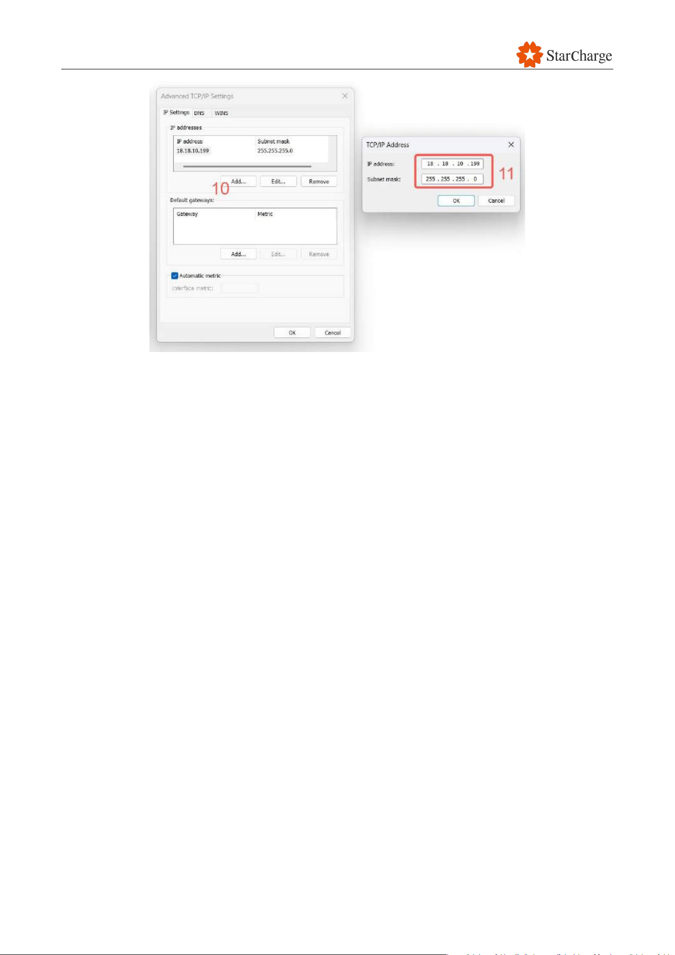
(1) Disconnect the original Internet cable connected to the AM62 board and connect the laptop
directly to the AM62 board inside the User unit #1 with a workable Internet cable.
Figure 6-9 Network port of AM62 board
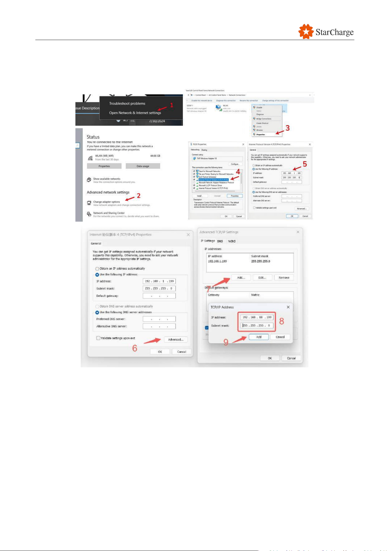
V 1.0.0 Star
55
Figure 6-10 Configure the IPV4 of the laptop
V 1.0.0 Star
56
6.6 Login web UI with the preset password
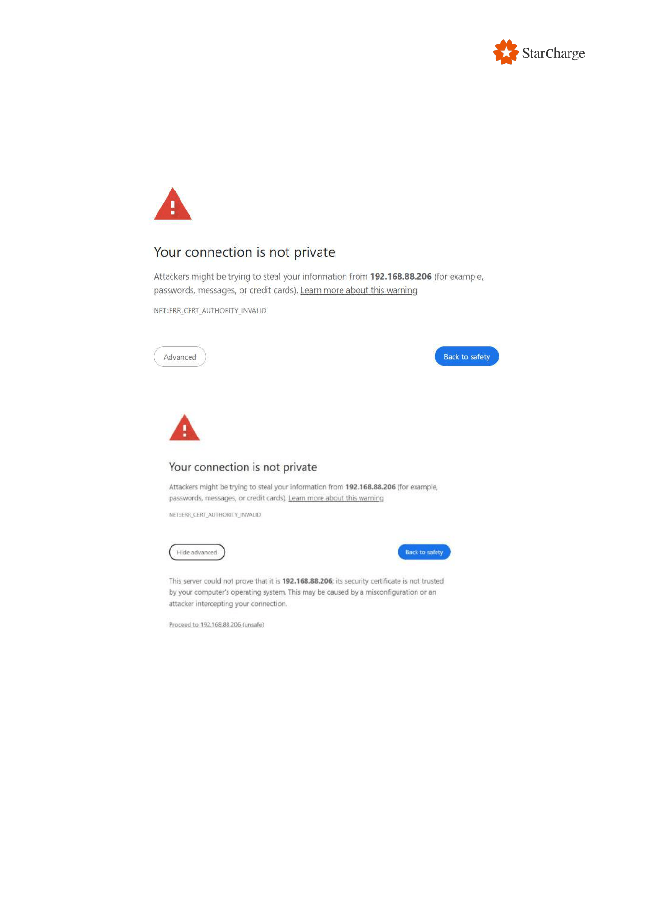
(1) On the computer web browser, type in website address"192.168.88.206" when laptop is
directly connected to the AM62 board. The commissioning tool login page should appear.
Note: A security message might appear: "Connection not private", click advanced and
proceed to access the web server login page.
Figure 6-11 Login to the Web UI
(2) Click Advanced-Continue to 192.168.88.206 (unsafe)
(3) At the first connection on site, please enter the factory default password.:
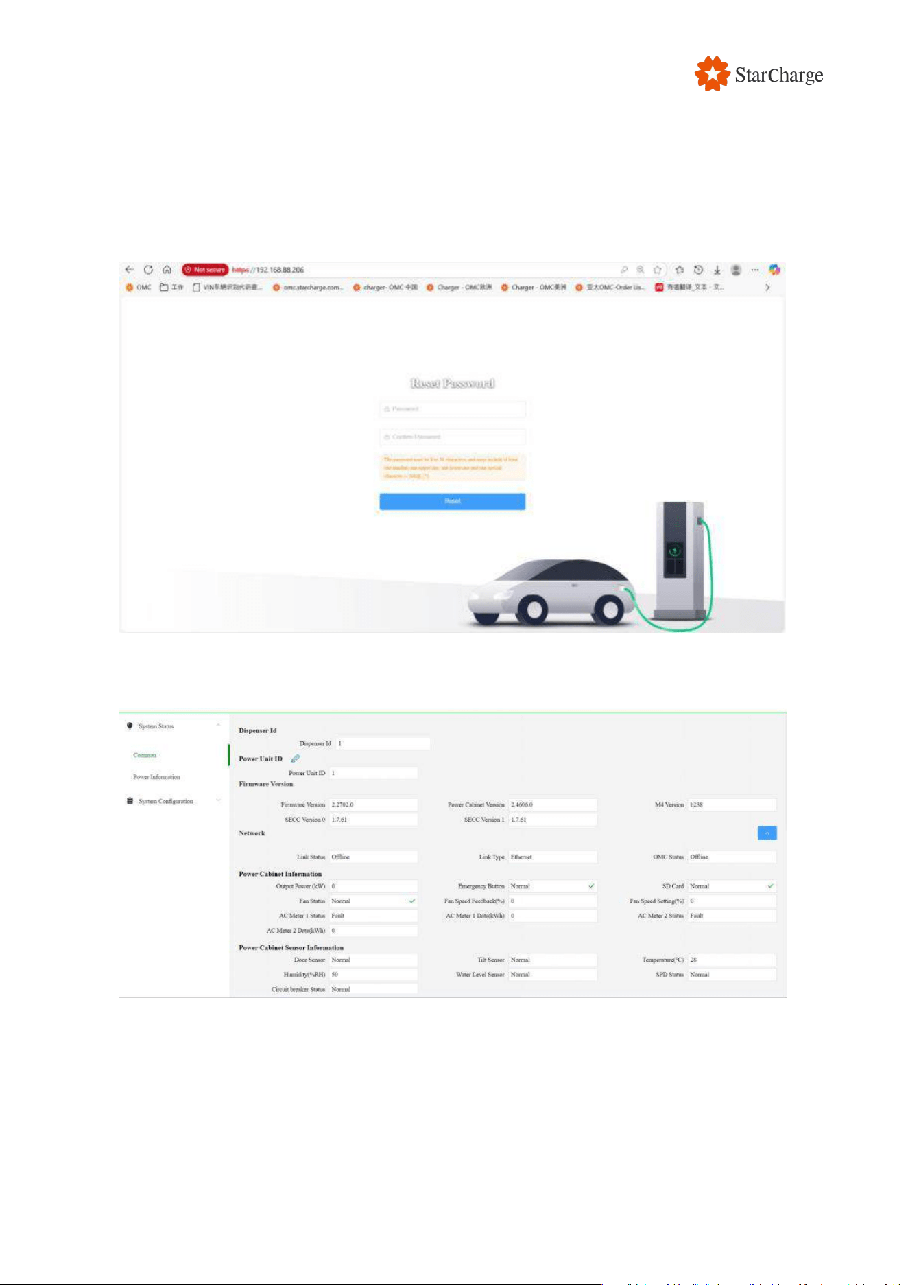
● Username: Admin.
● Password: WBdh26835941. ; please note that the password ends with a dot.
● Click Login.
V 1.0.0 Star
57
If the AM62 board is re-updated via the SD card (Require product model number, contact
StarCharge service team for configuration), the initial login password is: 1234. After logging in, it is
recommended to change the password to: WBdh26835941. ;please note that the password ends
with a dot.
Figure 6-12 Reset the password
(4) After creating the new password, the web server system status screen should appear.
Figure 6-13 Successful login to the webUI
(5) You can change the language of the commissioning interface.
(6) You can log out.
V 1.0.0 Star
58
6.7 The unique IP address setting of the user unit
6.7.1 RealGunID configuration (Important)
The communication between the power cabinet and the user units is established via Ethernet.
Therefore, each user unit must have a unique IP address to avoid address conflicts. This chapter
mainly explains how to set the parameters so that the IP address of each user unit becomes unique.
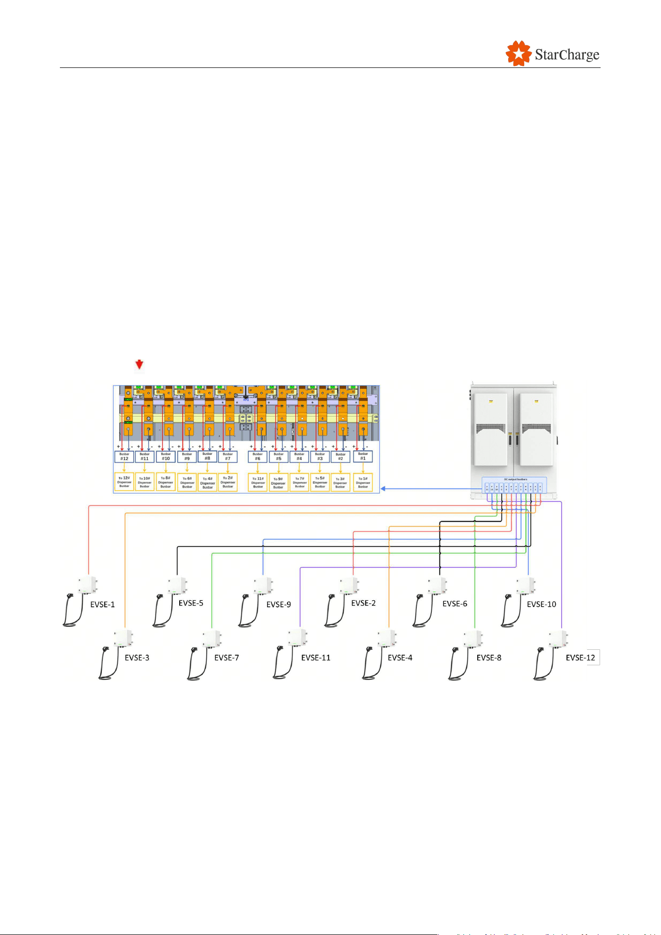
The Split System Dispenser charging connectors RealGun ID are based on how the DC cables are
connected to Power Cabinet copper Busbar. After Real ConNum is configured, the IP address of
the dispenser web will change to 192.168.1.1XX (XX = smaller Real ConNum). This parameter
setting is strongly related to Chapter 2 of the Cable Wiring Manual.
6.7.1.1 Complimented with NovaV4
The numbering of the copper Connectors in the power cabinet back door is as follows: 1
、
2
、
3
、
4、 5、 6、 7、 8、 9、 10、 11、 12 (From right to left).
Figure 6-14 Numbering of the copper busbars in the power cabinet
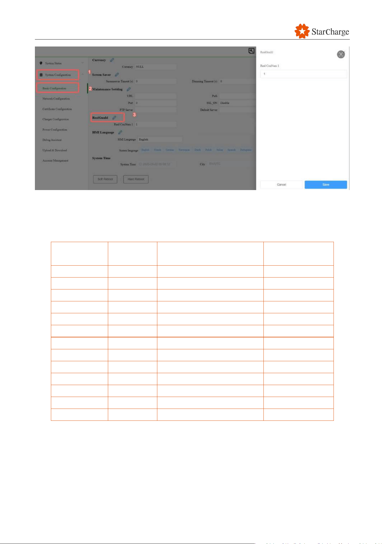
(1) Navigation panel: System Configuration >> Basic Configuration >> RealGunID.
(Under ConnectorID Mapping Enable situation )Real ConNum 1 corresponds to User Unit Num
[X] ,refer to the table below;
V 1.0.0 Star
59
Figure 6-15 RealgunID Settings Guide
(2) Click Basic Configuration-RealGunID, RealGunID must be configured for each charging connector
according to table below.
(3) The settings for RealConNum and the unique IP address generation rules are as follows.
User Units
Num.
Busbar
Real ConNum1 Setting
(ConnectorID Mapping Enable)
New IP address
#1
Busbar 1
1
192.168.1.101
#2
Busbar 7
2
192.168.1.102
#3
Busbar 2
3
192.168.1.103
#4
Busbar 8
4
192.168.1.104
#5
Busbar 3
5
192.168.1.105
#6
Busbar 9
6
192.168.1.106
#7
Busbar 4
7
192.168.1.107
#8
Busbar 10
8
192.168.1.108
#9
Busbar 5
9
192.168.1.109
#10
Busbar 11
10
192.168.1.110
#11
Busbar 6
11
192.168.1.111
#12
Busbar 12
12
192.168.1.112
Power Cabinet
192.168.1.136
Table 6-1 RealID Settings Guide and IP Correspondence
(4) After Dispenser #1 Real ConNum is configured, continue to directly connect laptop to other
Dispenser’s AM62 board and change the RealGunID.
V 1.0.0 Star
60
(5) After all Dispensers Real ConNum are configured, reconnect all the Internet cable back to
AM62 board and reboot all dispensers.
Attention:
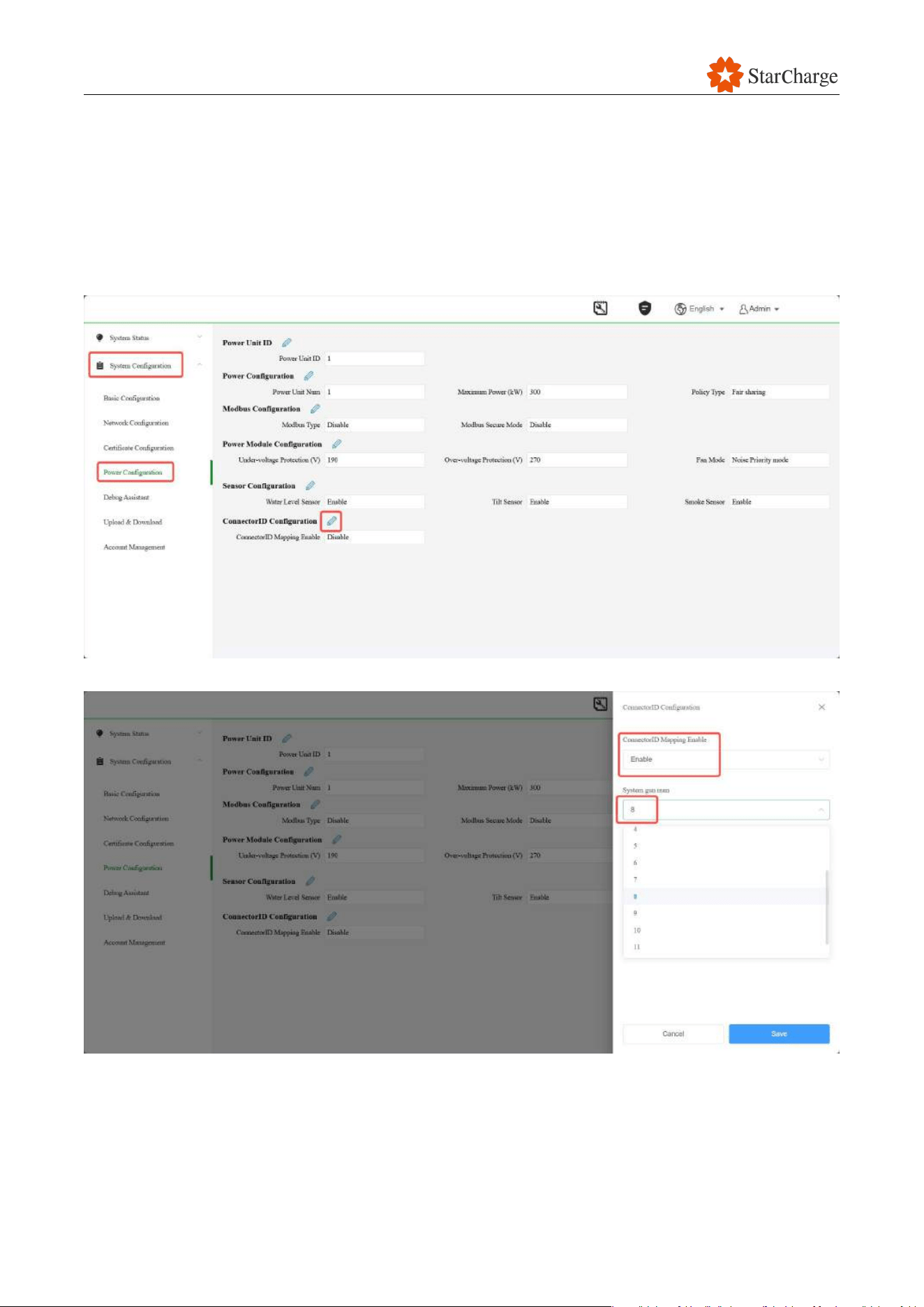
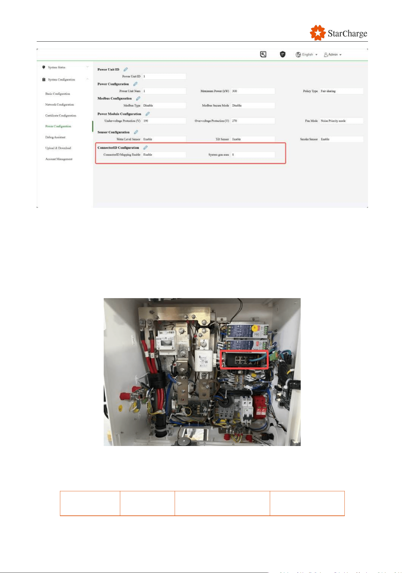
Must enable ConnectorID Mapping Enable function in power cabinet web page (192.168.1.136).
1. Log in to 192.168.1.136 and go to System Configuration-Power Configuration and click the icon
to edit
2. Enable the function and select Symtem gun num based on real situation
3. Click save button and check the if the configurations are correctly saved as figure below
V 1.0.0 Star
61
6.7.2 Login to the charger via the unique IP address
After setting all the RealGunID parameters for each user unit and completing the reboot, please log
in to each user unit using its unique IP address. Since the split system power cabinet is
independent and unique, the IP address of the power cabinet is always 192.168.1.136.
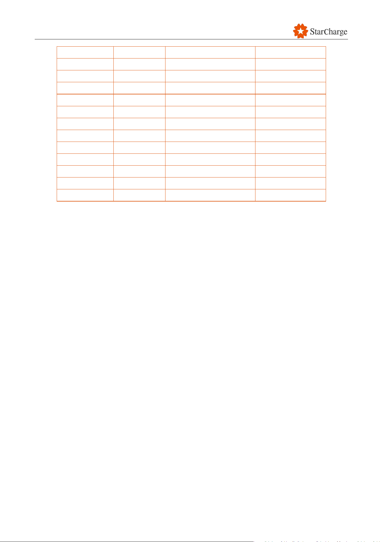
(1) Connect laptop to any Dispenser’s switch empty port.
Figure 3-16 Connect laptop to any Dispenser’s switch empty port
(2) Login to the user unit's Web UI with new IP address as shown below and keep the web open
for next steps.
User Units
Num.
Busbar
Real ConNum1 Setting
New IP address
V 1.0.0 Star
62
#1
Busbar 1
1
192.168.1.101
#2
Busbar 7
2
192.168.1.102
#3
Busbar 2
3
192.168.1.103
#4
Busbar 8
4
192.168.1.104
#5
Busbar 3
5
192.168.1.105
#6
Busbar 9
6
192.168.1.106
#7
Busbar 4
7
192.168.1.107
#8
Busbar 10
8
192.168.1.108
#9
Busbar 5
9
192.168.1.109
#10
Busbar 11
10
192.168.1.110
#11
Busbar 6
11
192.168.1.111
#12
Busbar 12
12
192.168.1.112
Power Cabinet
192.168.1.136
Table 6-2 RealID Settings Guide and IP Correspondence
6.8 OCPP connection
Please refer to the power cabinet debugging manual for OCPP connection.
Configure OCPP configurations in Power Cabinet Web UI 192.168.1.136.
6.9 Introduction to the User Unit Web UI
6.9.1 Verify the status of the user unit
● Check user unit status
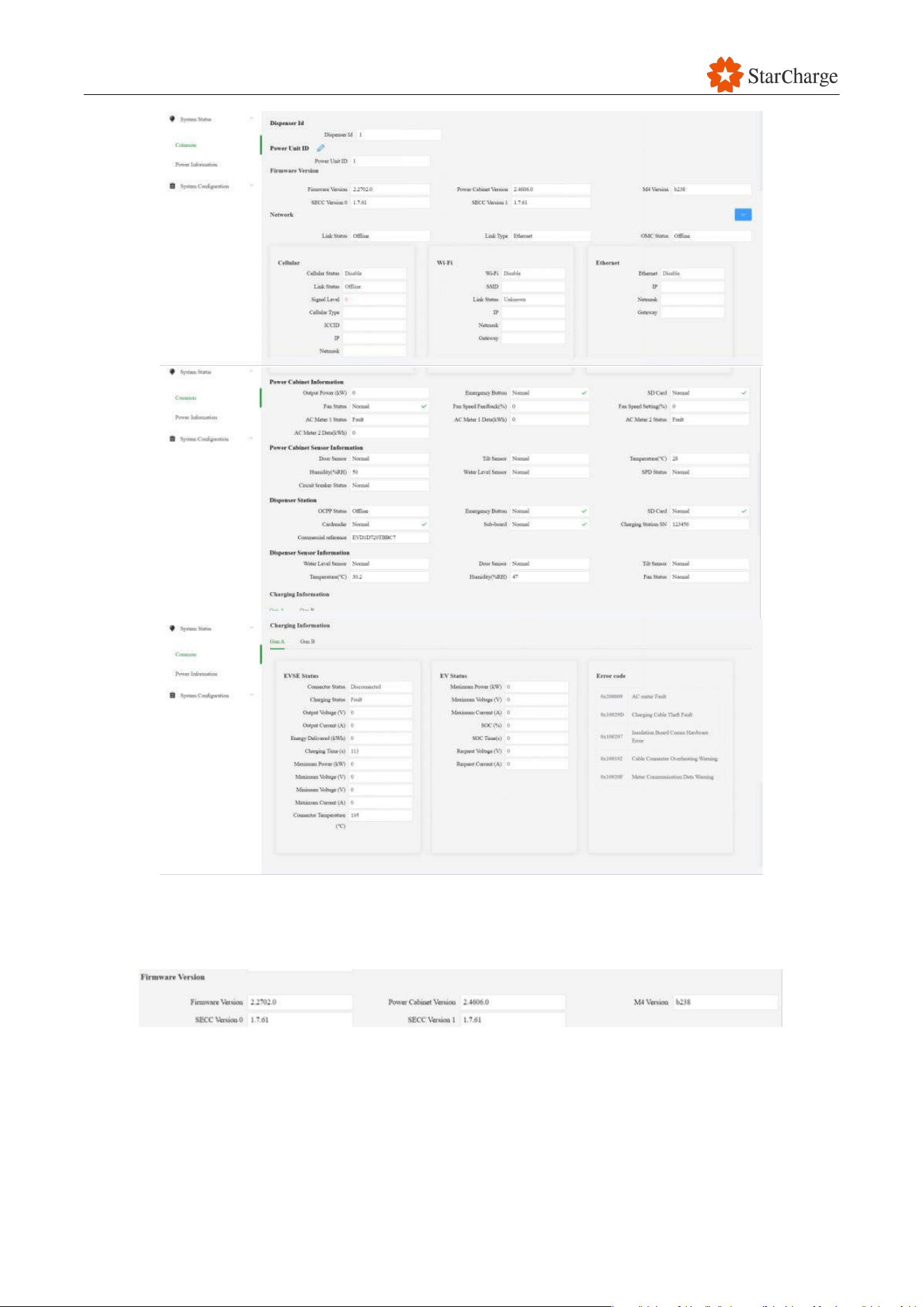
Before starting to modify the charging station parameters, it is recommended to check the different
status of the equipment on the System Status page.
Navigation path: System Status > Common.
V 1.0.0 Star
63
Figure 6-17 Status of the user unit
6.9.1.1 Firmware Version
Figure 6-18 Version of the user unit
Check the current firmware version is visible and check if it is the latest version
If it's not the case, update the firmware version (optional).
V 1.0.0 Star
64
6.9.1.2 Network Status
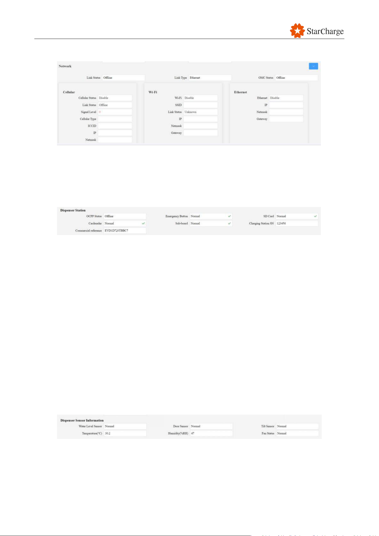
Figure 6-19 Network status of the user unit
Displays the active Link Type: Wi-Fi, 4G or Ethernet. Check if the Link Status is online after it has
been commissioned, it may be offline before commissioning.
6.9.1.3 Dispenser Station
Figure 6-20 Status of the user unit
● OCPP Status: Displays the connectivity status to the OCPP backend.
● Emergency Button: Displays the status of the Dispenser Emergency Button whether Normal
or Fault. It should be in Normal status
● SD card: Displays the status of the SD card of Dispenser AM62 board whether Normal or Fault.
It should be in Normal status
● Cardreader: Displays the status of the RFID card reader whether Normal or Fault. It should be in
Normal status
● Sub-board: Displays the status of the M4 board whether Normal or Fault. It should be in Normal
status
● Charging Station SN: Displays the Serial Number
of this Charging Station matching its name
plate
● Commercial Reference: Displays the Commercial reference of this Charging Station.
6.9.1.4 Dispenser Sensor Information
Figure 6-21 Sensor information of the user unit
● Water Level Sensor: Normal
● Door Sensor: Normal
● Tilt Sensor: Normal
V 1.0.0 Star
65
● Temperature (℃): Environmental temperature
● Humidity(%RH): Environmental humidity
● Fan status: Normal
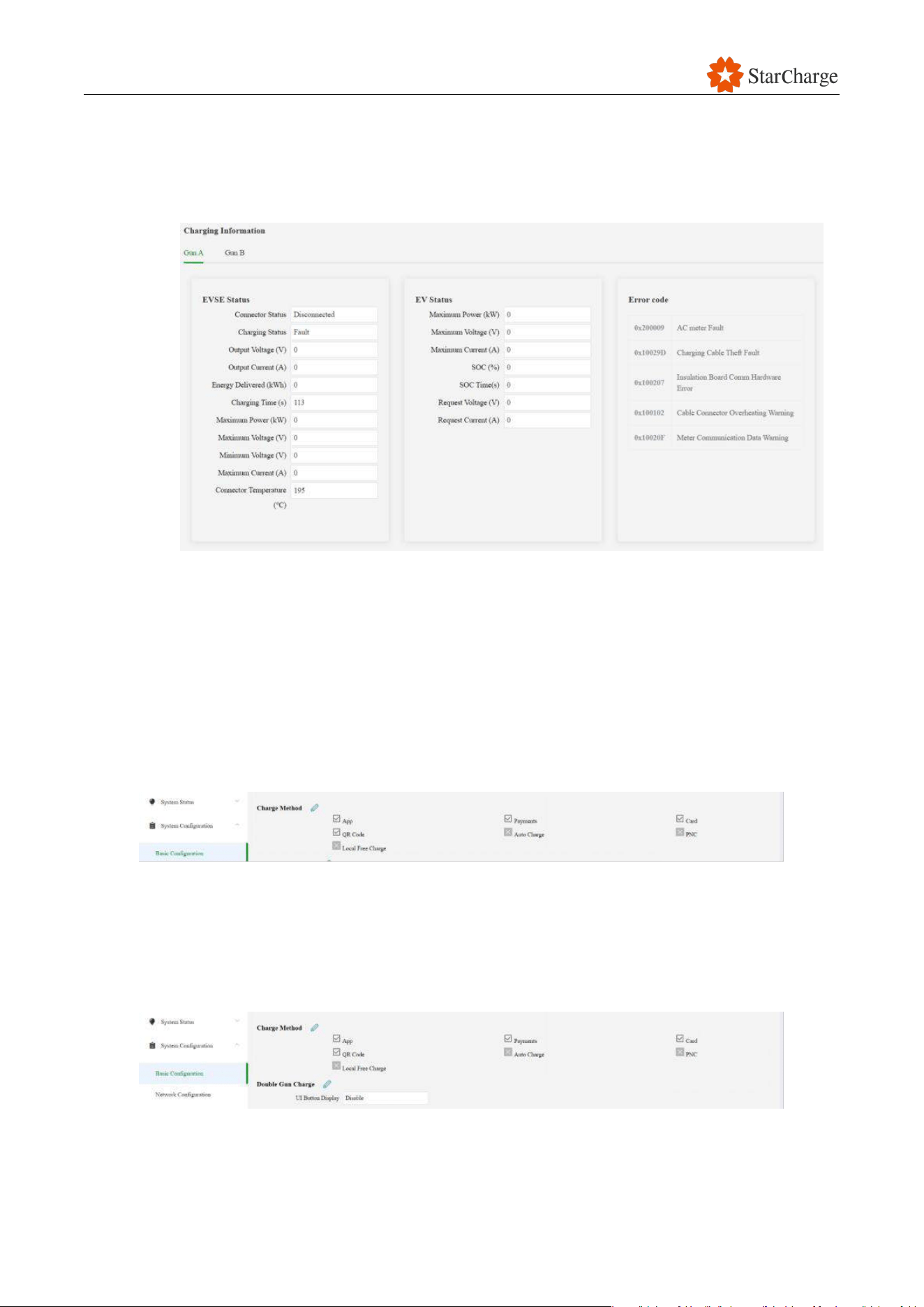
Figure 6-22 Charging information of the user unit
6.9.2 Basic configuration setting of the user unit
Navigation panel: System Configuration > Basic Configuration.
6.9.2.1 Charge Method (Optional)
Click the pencil icon to modify parameters. (Enable / disable)
Figure 6-23 Charging method of the user unit
Note: Charge method here just to modify the icons shown on HMI, corresponding methods are
based on Power cabinet Authentication Mode
6.9.2.2 Double Gun Charge (Optional)
Figure 6-24 Charging method of the user unit
Click the pencil icon to modify parameters. (Enable / disable).
Note: Double Gun Charge mainly for EV BUS with 2 charging slots. Keep as default setting (Disable)

V 1.0.0 Star
66
if not required.
6.9.2.3 UI Manual Stop Charging Method (Optional)
Click the pencil icon to modify parameters. (Enable / disable)
Figure 6-25 Stop method of the user unit
Note:
● The stop button for indication how to stop is always activated by default when authentication
mode other than Mac address or Free charging is selected.
● When Mac address authentication or Free charging mode is selected the button is disable by
default (to avoid anyone can stop a session). But it can be activated in case of need.
6.9.2.4 HMI Language (Optional)
Note: This step is needed to determine which languages the EV driver will be able to select on the
HMI of the charger. The maximum number of languages is 12.
(1) Click System Configuration - Basic Configuration - HMI Language.
(2) Click the pencil icon to modify parameters.
(3) Remove the unnecessary languages and add the required languages from the drop-down list.
(4) Save the settings and reboot, check if the settings are correctly shown on the screen.
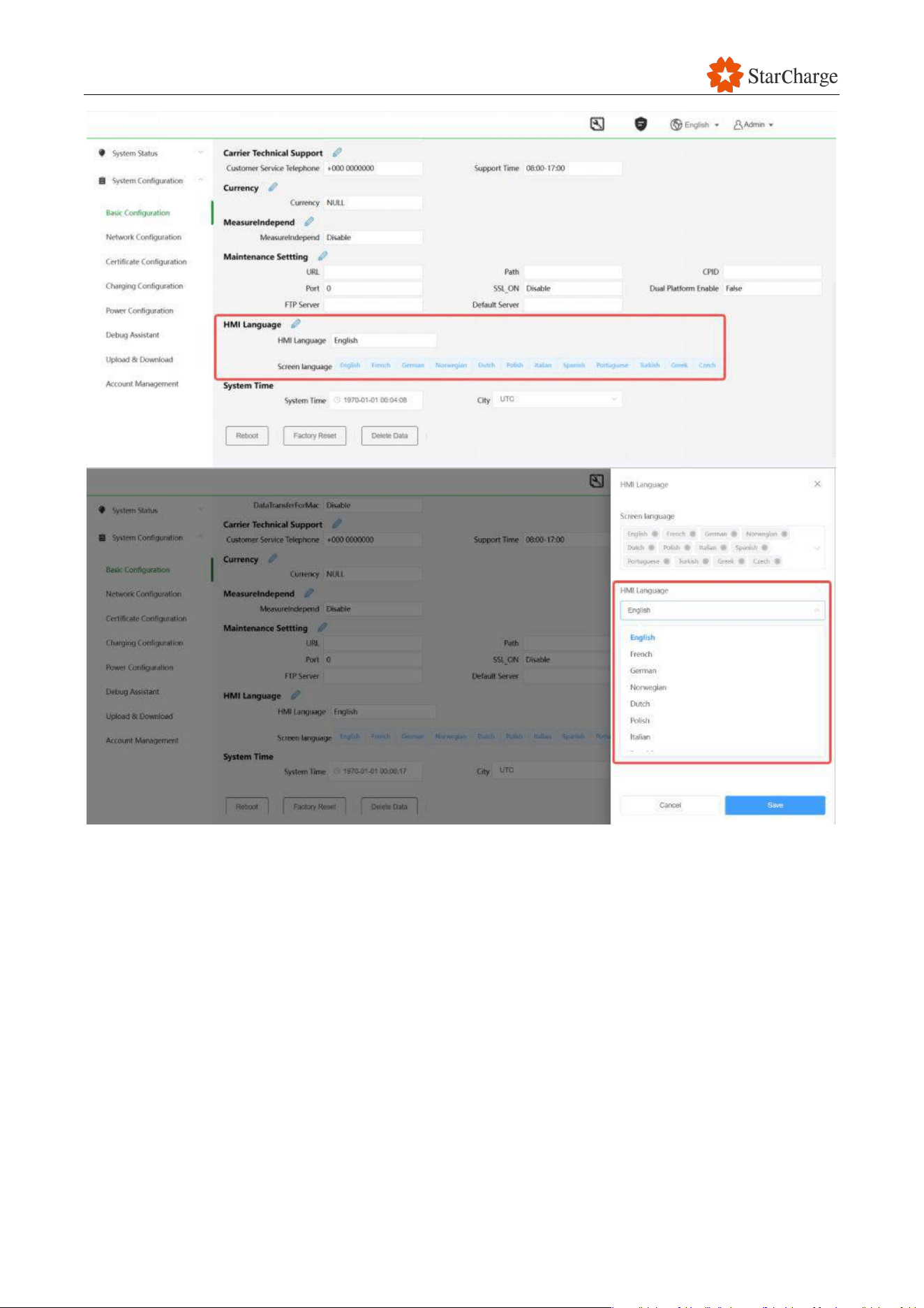
V 1.0.0 Star
67
Figure 6-26 Language select of the user unit
6.9.2.5 System Time (Optional)
Note: Time setting will automatically change if the Charging Station is connected to an OCCP
backend. But even in that case time and date need to be set initially, to ensure the first
communication with the OCPP backend. Time zone city needs to be selected.
(1) Find System Time.
(2) Click on the System time box to set manually or click Now to synchronize with the computer
time and date.
(3) Use the City drop-down menu to select the suitable time zone.
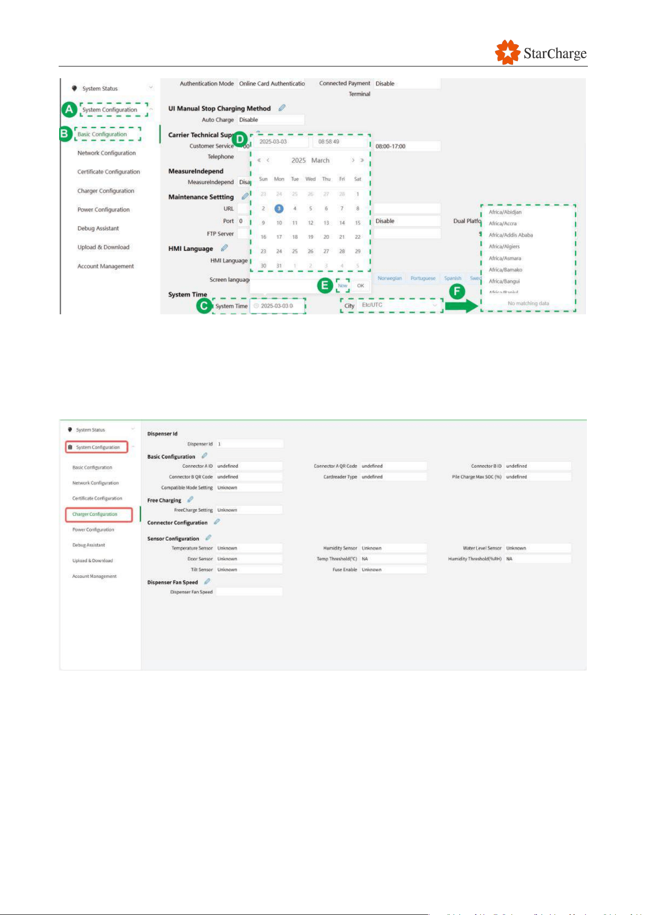
V 1.0.0 Star
68
Figure 6-27 System time setting of the user unit
6.9.3 Charger configuration (Optional)
Navigation panel:System Configuration > Charger configuration.
Figure 6-28 Charger configuration of the user unit
6.9.3.1 Basic Configuration
(1) System Configuration - Charger configuration - Basic Configuration.
(2) Click the pencil icon to modify parameters.
(3) Set the Alternating Charging parameters (Optional).
(4) Check the Connector ID is set as 1 and 2. No need to modify factory setting.
(5) Set the QR
Code for each connector (Optional).
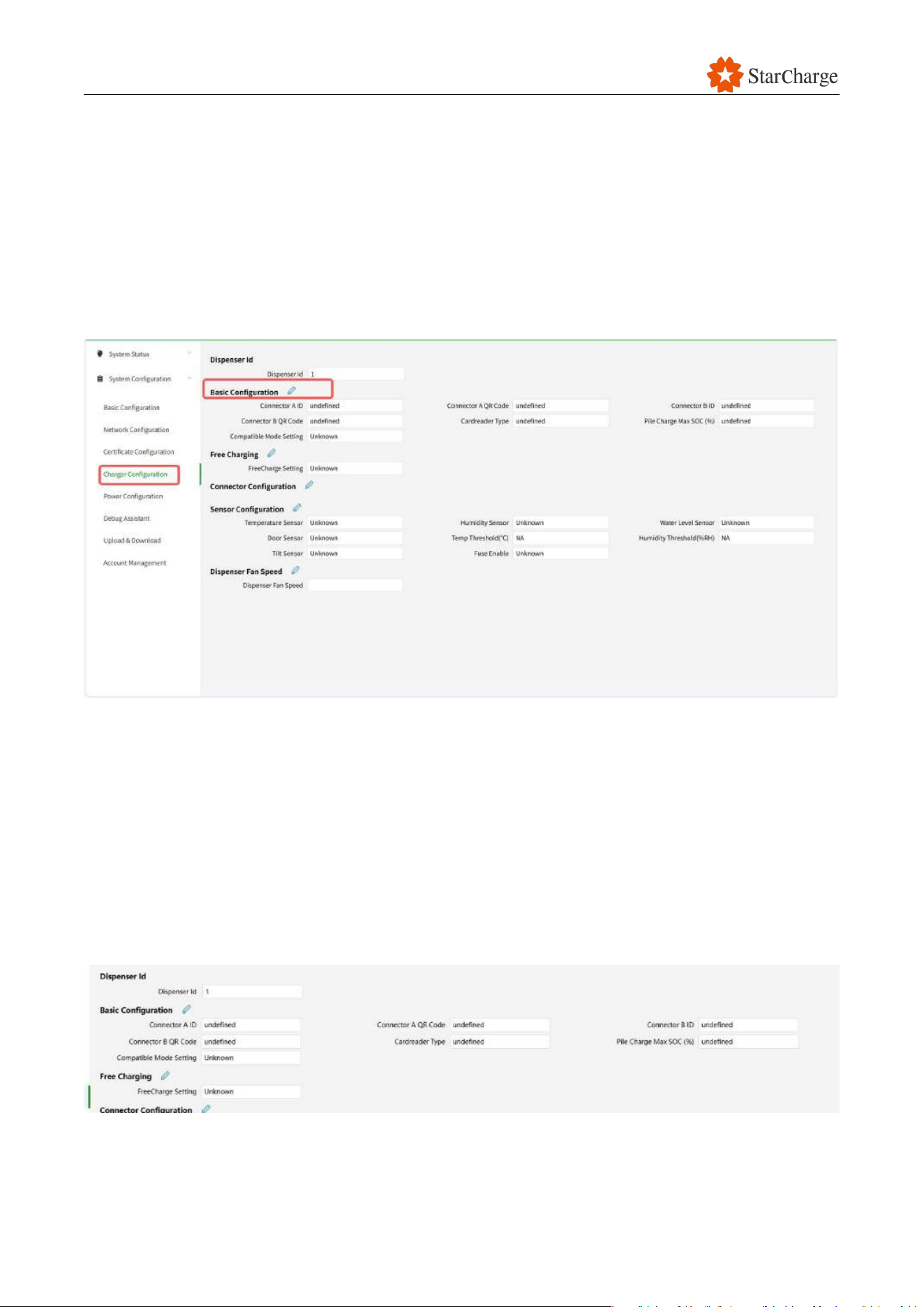
V 1.0.0 Star
69
QR Code must be unique to each charging connector and Charging Station and must be within 40
characters.
This value can be set as a simple alphanumerical ID which could be used by Charge Point Operator
application for charger and charging connector authentication.
It could be also a web address to directly link to a Charge Point Operator application. Once the QR
Code is set it will appear on the authentication screen as one of the options to provide
authentication for a backend to authorize a charging session.
(6) Click Save.
Figure 6-29 Charging basic configuration of the user unit
6.9.3.2 Free Charging (Optional)
(1) System Configuration - Charger configuration - Free Charging
(2) Click the pencil icon to modify parameters.
(3) Set the Free Charging parameters (Optional).
If customer backend platform enables this function, when ocpp offline, charger can start charging
for free. Keep as default setting (Disable) if not required.
Figure 6-30 Free charging configuration of the user unit
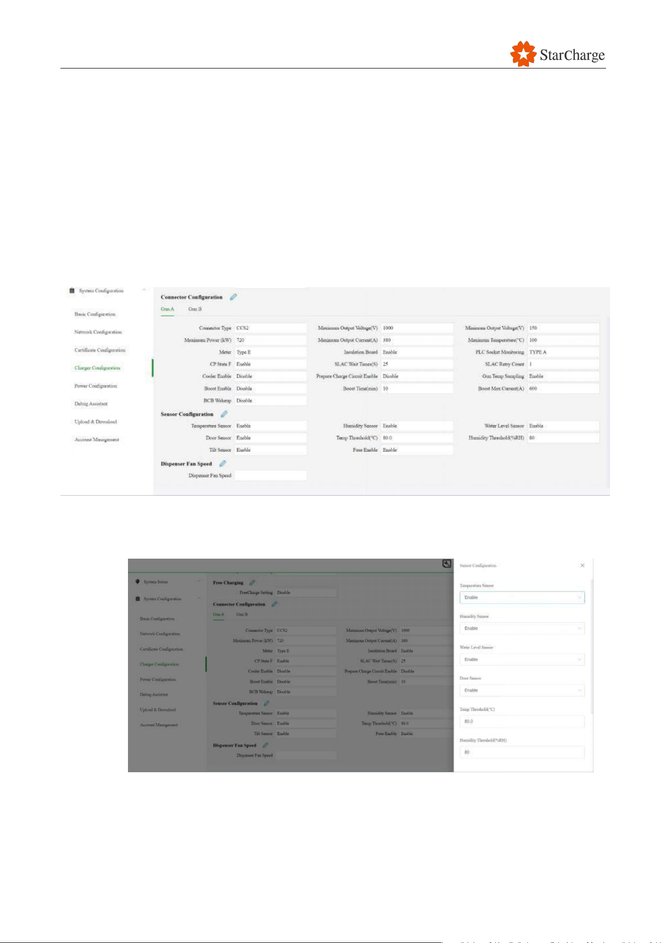
V 1.0.0 Star
70
6.9.3.3 Connector Configuration (Optional)
This parameter has already been set during the factory debugging process and no further settings
are required.
(1) System Configuration - Charger configuration - Connector Configuration.
(2) To modify these parameters, click on the pencil icon.
(3) Configure the Guns respectively
(4) Set the Maximum Output Current and/or Maximum Output Voltage allowed to the desired load
or set the Maximum Power delivered to the desired power.
(5) Set the Boost Enable to enable boost mode. (Contact StarCharge team for detailed settings)
Figure 6-31 Connector configuration of the user unit
6.9.3.4 Sensor Configuration (Optional)
Figure 6-32 Sensor configuration of the user unit
(1) System Configuration - Charger configuration - Sensor Configuration
(2) To modify sensors parameters, click on the pencil icon.
(3) Set the required parameters for each sensor.

V 1.0.0 Star
71
(4) Click Save.
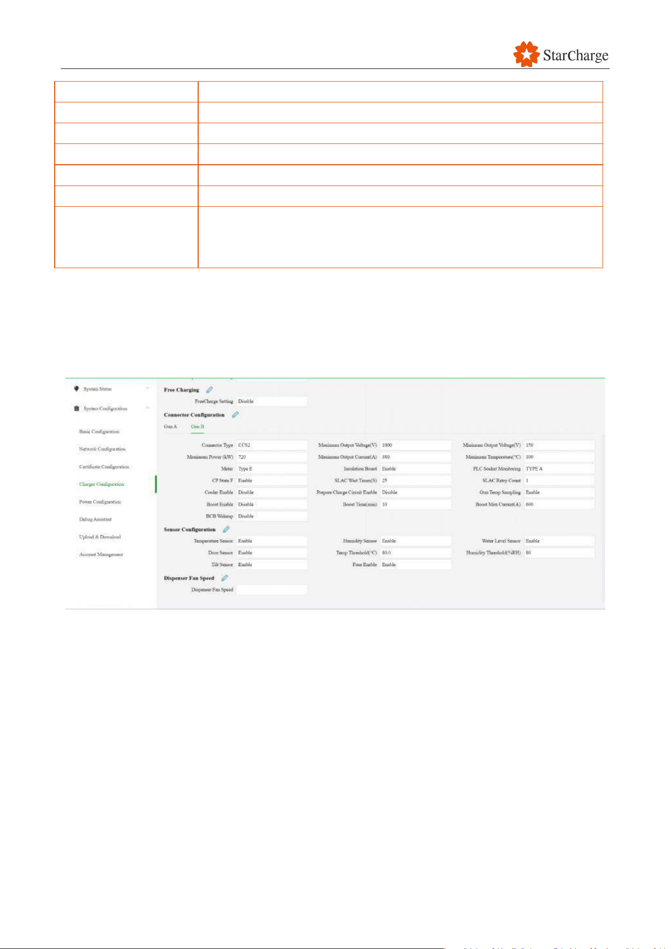
V 1.0.0 Star
72
Available Settings
Temperature sensor:
Internal temperature sensor. Must always be enabled.
Humidity Sensor:
Internal humidity sensor. Must always be enabled.
Water Level Sensor:
Internal water flooding sensor. Must always be enabled.
Door Sensor:
Door open detection sensor. Must always be enabled.
Humidity Threshold:
Door open detection sensor. Must always be enabled.
Tilt Sensor:
Internal Tilt/shock sensor that will interrupt output power/charging
session if the sensor detects a tilt or strong impact. Must always be
enabled.
Table 6-3 The function of each sensor
6.9.3.5 Dispenser Fan Speed (Optional)
Set the Fan speed to test the Fan function, set the value to 0 and click save after the test is
completed.
Figure 6-33 Dispenser fan speed of the user unit
6.9.4 Debug Assistant (Optional)
Navigation panel:System Configuration >> Debug Assistant.
(1) Find Debug Assistant.
(2) Fan Speed: Enables activating the Fan at the entered speed from 0 to 100%.
(3) Fan Control: Start/Stop the Fan manually.
(4) AC Contactor: Open/Close the AC Contactor manually.
(5) DC Contactor Control: Open/Close the DC Contactors K1 or K2 for each Vehicle Connector.
(6) PDU: Open/Close contactors on PDU.
(7) Power Test: Simulates a charging session on the selected connector by requesting voltage and
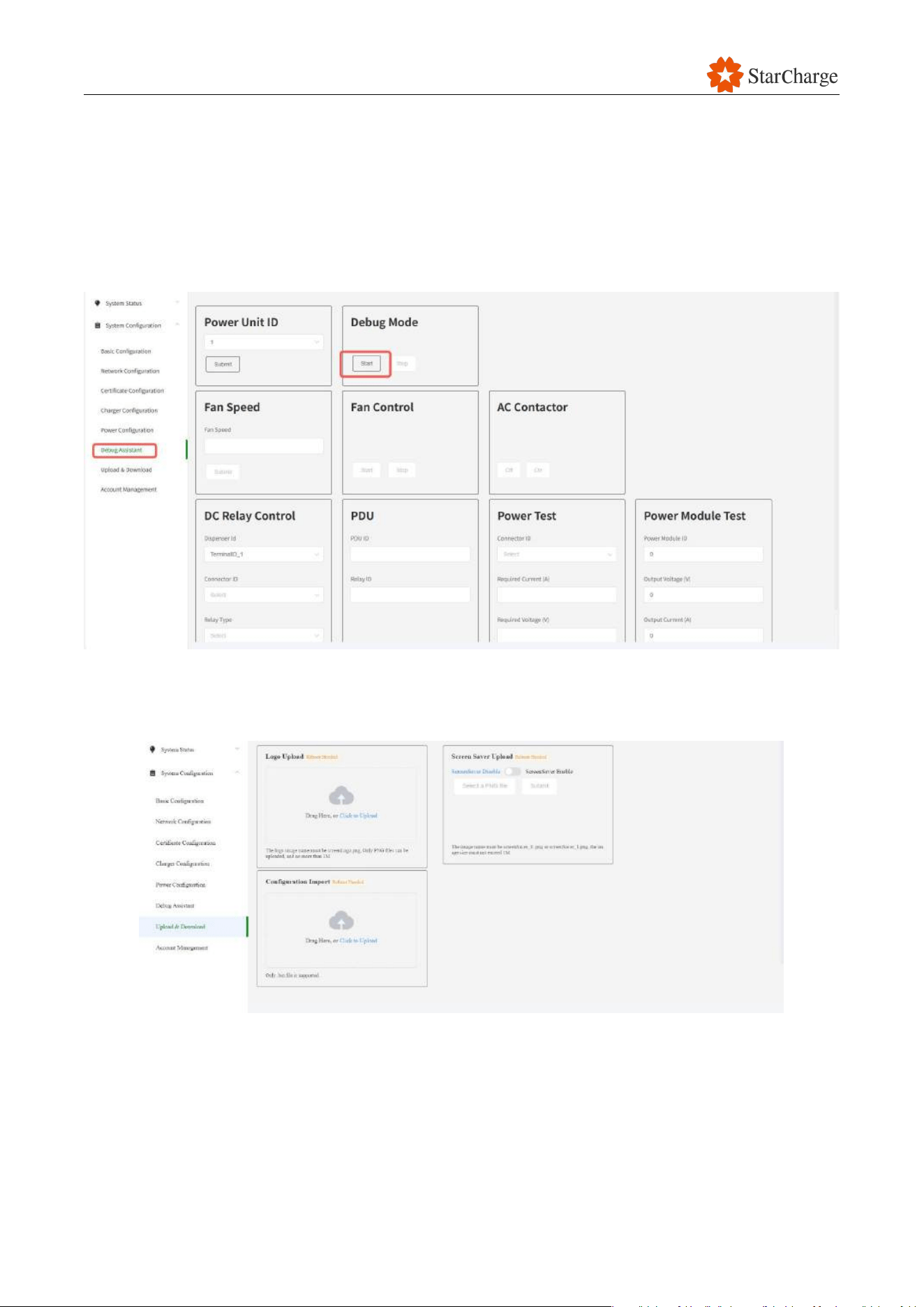
V 1.0.0 Star
73
current.
(8) Power Module Test: Set Power Module ID, Output Voltage, Output Current to test Power
Module.
Attention:
Do not use this function without Technical engineer supporting.
Figure 6-34 Debug model of the user unit
6.9.5 Upload (Optional)
Figure 6-35 Debug model of the user unit
(1) Under System Configuration.
(2) Find Upload & Download.
(3) Then Upload Logo (Check with StarCharge team for Logo size details).
(4) Then Upload Screen Saver (Check with StarCharge team for Logo size details).
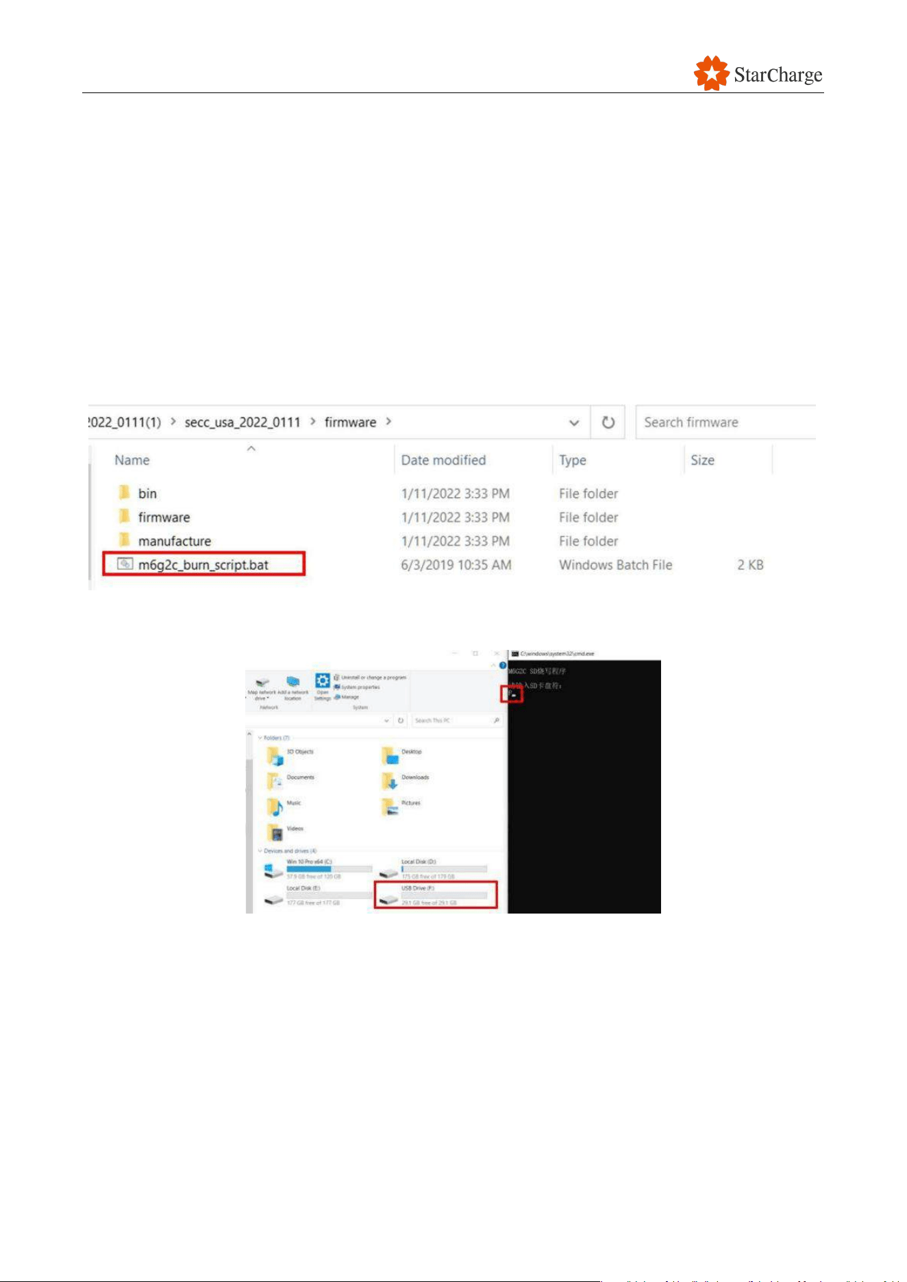
V 1.0.0 Star
74
6.9.6 Account Management
The password for logging into the charger's Web UI can be added or deleted.
6.10 Manually upgrade firmware
6.10.1 Update SECC via Micro SD card
(1) Insert a Micro SD card into a laptop (Specific card for programming, don’t use the original Micro
SD card inside the EVSE).
(2) Enter the folder (A6G2C-WB128LI-Flash) and double click the file (a53_burn_script.bat).
Figure 6-36 Update SECC via Micro SD card #1
(3) Enter the driver of Micro SD card. For example, the driver of my Micro SD card is “F”.
Figure 6-37 Update SECC via Micro SD card #2
(4) If there’s a warning shown as the figure below, enter “y” to confirm and wait for the file to be
copied completely.
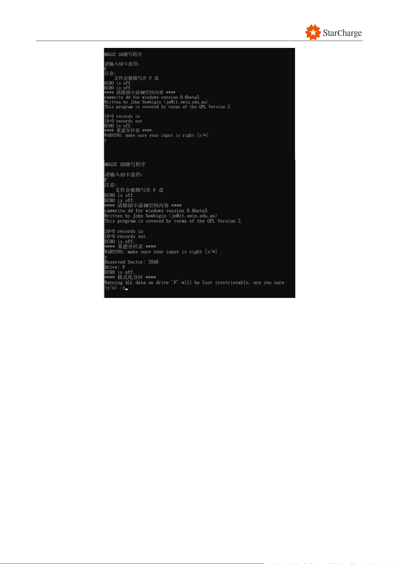
V 1.0.0 Star
75
Figure 6-38 Update SECC via Micro SD card #3
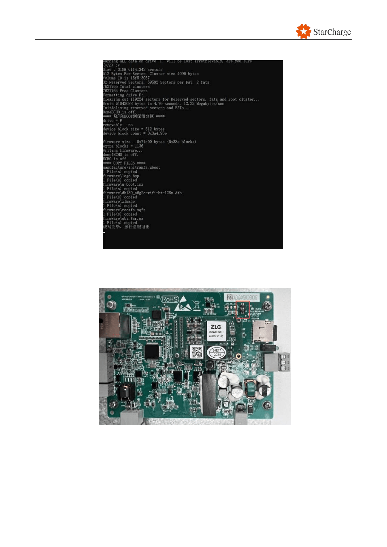
V 1.0.0 Star
76
(5) After successful copying, press any key to exit and finish programming the microSD card.
Figure 6-39 Update SECC via Micro SD card #4
(6) Power off the SECC board, insert the Micro SD card, and turn on both 2 switches marked red
shown in the figure below (“ON” Side).
Figure 6-40 Update SECC via Micro SD card #5
(7) Power on the board again, the update will begin.
Note: The LED light will flash continuously during the update.
(8) Power off the board after the LED light is solid on for 30 seconds.
(9) Return back both DIP switches to positions 1 and 2.
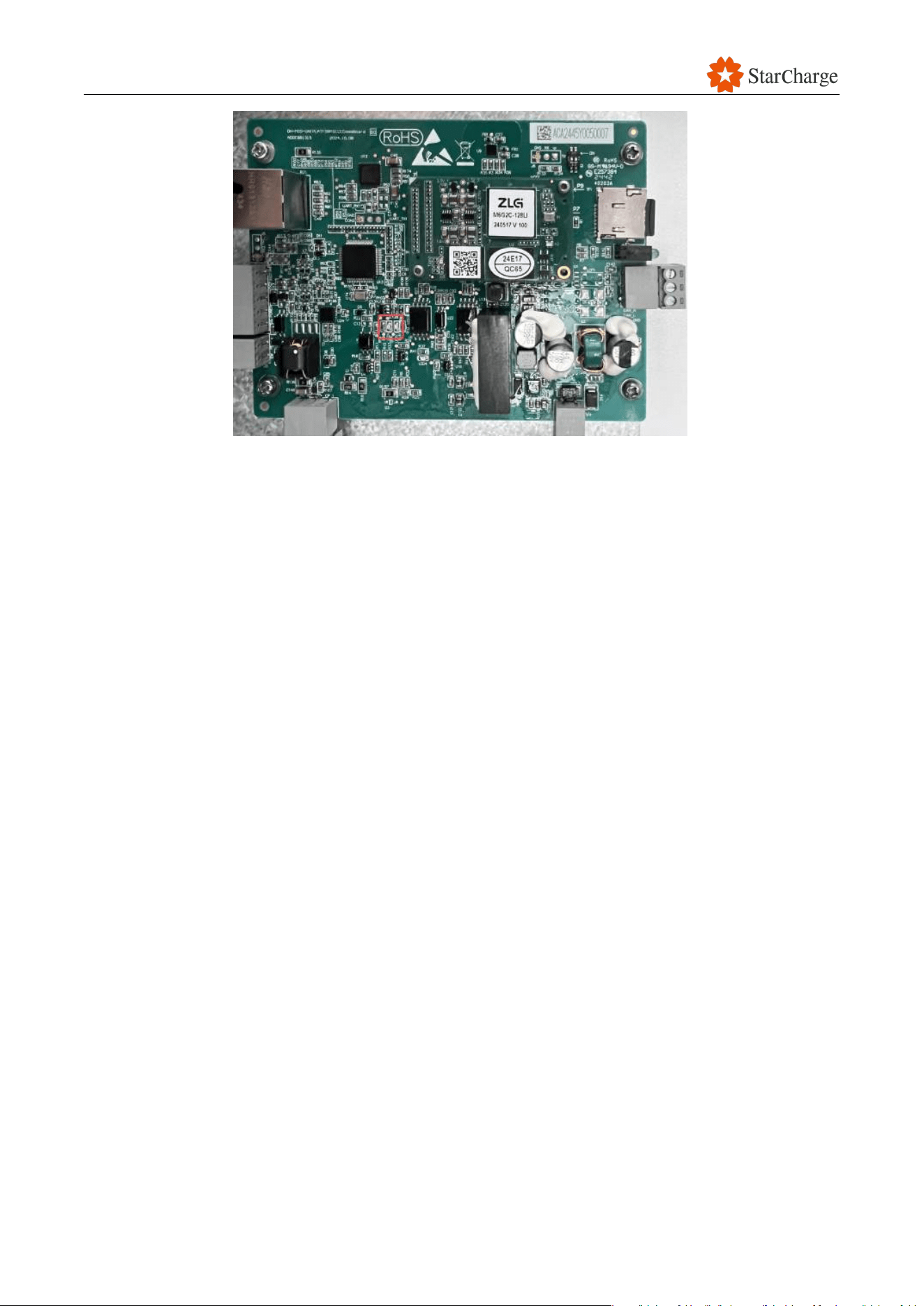
V 1.0.0 Star
77
Figure 6-41 Update SECC via Micro SD card #6
(10) Remove the programmed Micro SD card.
(11) Insert the original Micro SD card (in Step 8) back into the SECC board.
(12) Power on again to finish programming. It will take a little longer for the first reboot.
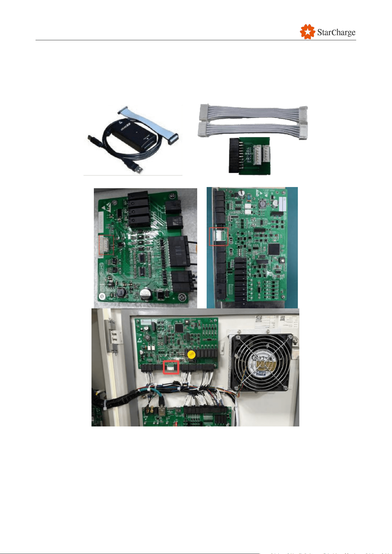
V 1.0.0 Star
78
6.10.2 Update M4 board (CB02)/PDU control board/Environmental monitoring board via
Micro SD card
(1) Connect the Jlink to the M4 board (CB02), the PDU control board, or the environmental
monitoring board.
Figure 6-42 Update M4 board (CB02)/PDU control board/environmental monitoring board via Jlink
#1
(2) Open "J-Flash V6.3.2"on the laptop.
(3) Choose the “.jlash” file.
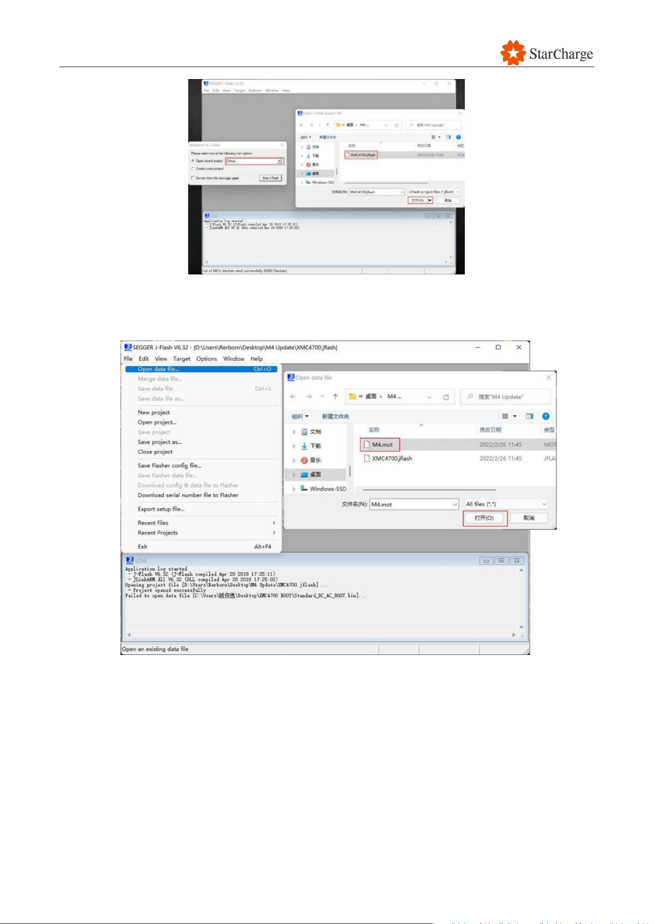
V 1.0.0 Star
79
Figure 6-43 Update M4 board (CB02)/PDU control board/environmental monitoring board via Jlink
#2
(4) Open the “. Mot” file.
Figure 6-44 Update M4 board (CB02)/PDU control board/environmental monitoring board via Jlink
#3
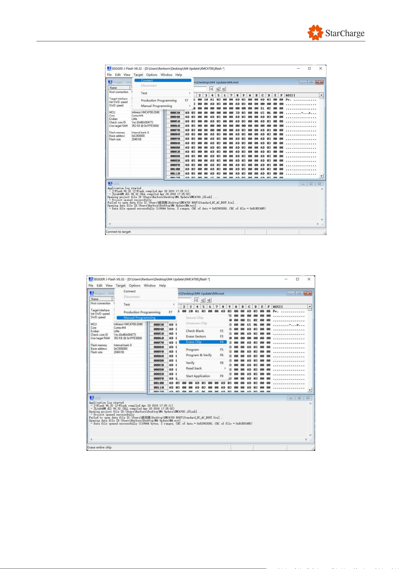
V 1.0.0 Star
80
(5) Click Target > Connect.
Figure 6-45 Update M4 board (CB02)/PDU control board/environmental monitoring board via Jlink
#4
(6) Click Target > Manual Programming > Erase Chip.
Figure 6-46 Update M4 board (CB02)/PDU control board/environmental monitoring board via Jlink
#5
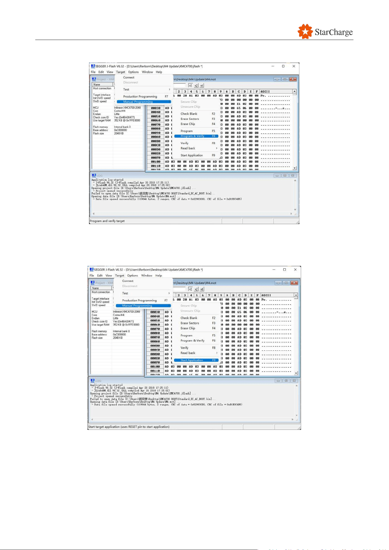
V 1.0.0 Star
81
(7) Click Target > Manual Programming > Program & Verify. Try again if it fails.
Figure 6-47 Update M4 board (CB02)/PDU control board/environmental monitoring board via Jlink
#6
(8) Click Target > Manual Programming > Start Application.
Figure 6-48 Update M4 board (CB02)/PDU control board/environmental monitoring board via Jlink
#7
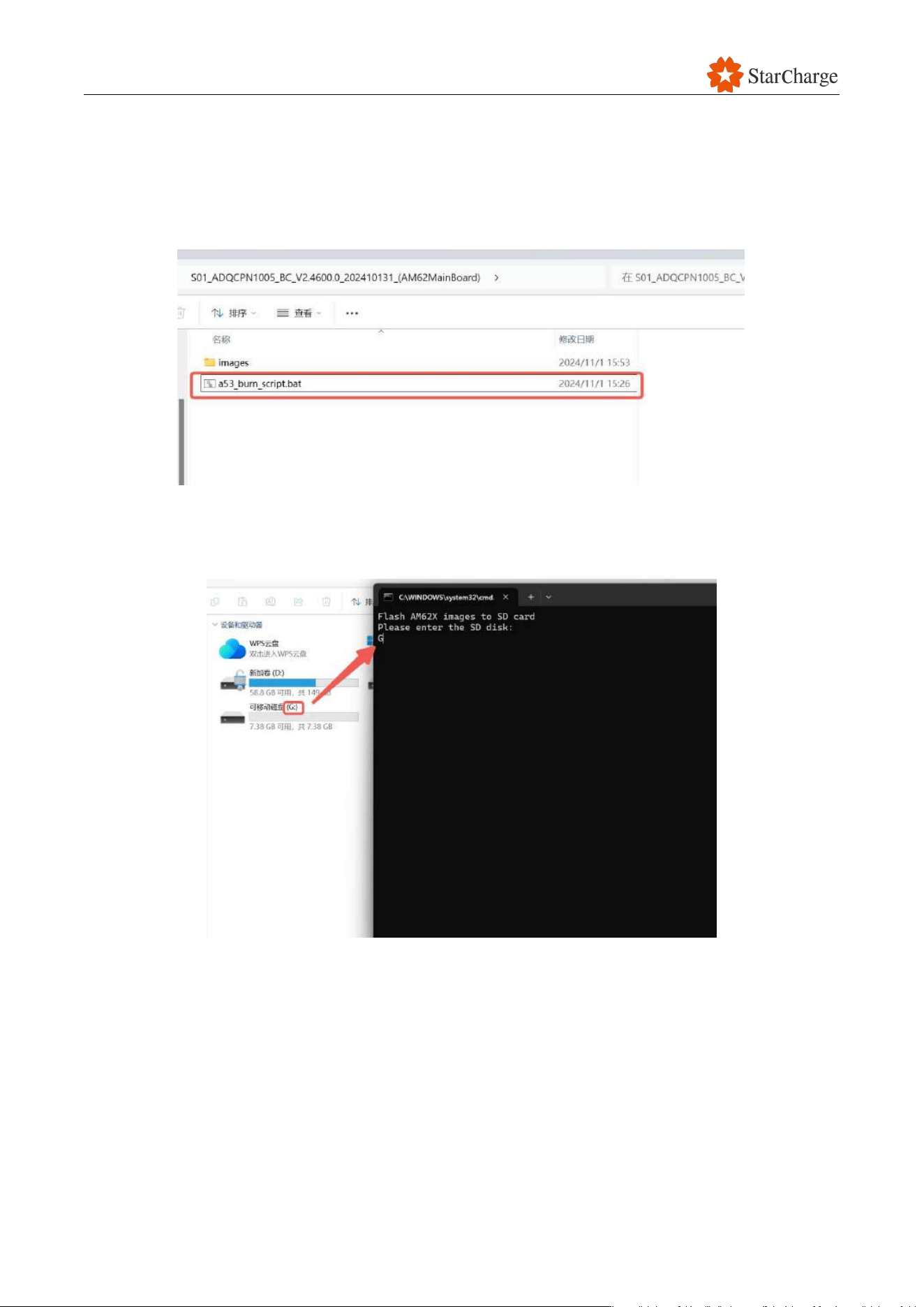
V 1.0.0 Star
82
6.10.3 Update AM62 board via Micro SD card
(1) Insert a Micro SD card into a laptop (specific card for programming, don’t use the Micro SD card
put in the EVSE).
(2) Enter the folder (AM62MainBoard) and double click the file (m6g2c_burn_script.bat).
Figure 6-49 Update AM62 via Micro SD card #1
(3) Enter the driver of Micro SD card. For example, the driver of my Micro SD card is “G”, then click
the enter.
Figure 6-50 Update AM62 via Micro SD card #2
(4) Click Enter again.
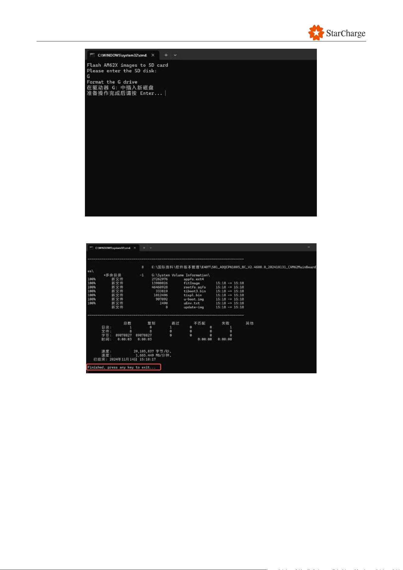
V 1.0.0 Star
83
Figure 6-51 Update AM62 via Micro SD card #3
(5) After successful copying, press any key to exit and finish programming the microSD card.
Figure 6-52 Update AM62 via Micro SD card #4
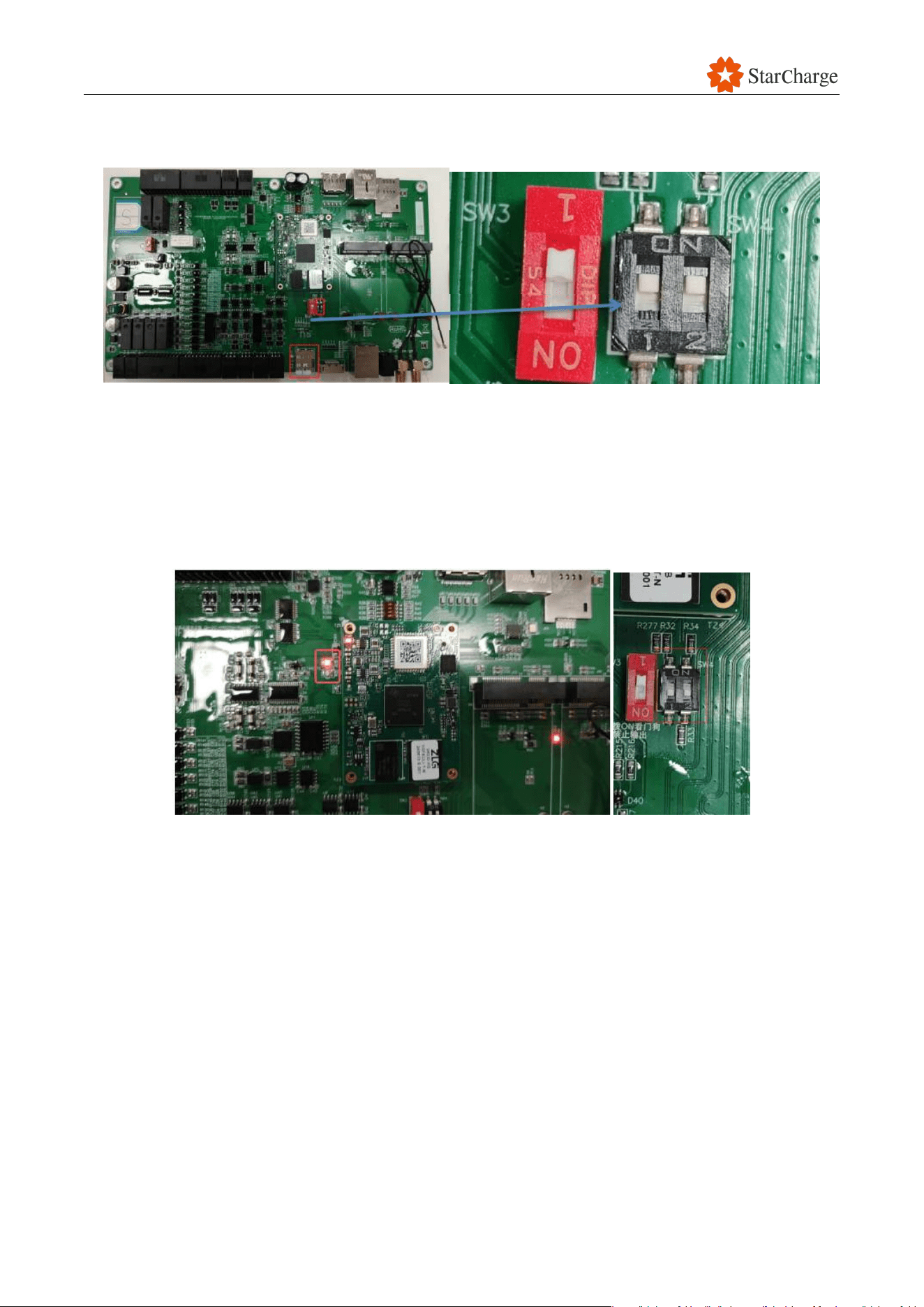
V 1.0.0 Star
84
(6) Power off the AM62 board, insert the Micro SD card, and turn both 2 switches marked black
shown in the figure below to ON position.
Figure 6-53 Update AM62 via Micro SD card #5
(7) Power on the board again, the update will begin.
Note: The LED light will flash continuously during the update.
(8) If the indicator effect is heartbeat (the default indicator effect configured in the kernel: Blink
twice fast -> Off - Off -> Blink twice fast), the AM62 is successfully updated, wait for 30
seconds and power off, and then switch both switches back to positions 1 2.
Figure 6-54 Update AM62 via Micro SD card #6
(9) Remove the programmed Micro SD card, insert the original Micro SD card back into the AM62
mainboard, and then power on again to finish programming. It will take a little longer for first
reboot.

V 1.0.0 Star
85
6.11 Charging function check
6.11.1 Charging testing
Follow the instructions in the user manual to perform the charging test. Complete the checkpoints
and record any unauthorized items in table below.
6.11.2 Hardware function check
Check whether the following hardware functions meet the requirements. Complete the checkpoints
and record any unauthorized items in table below.
● Door sensor: Open the EVSE door while charging. The EVSE should stop charging.
● Tilt sensor: Tilt the tilt sensor inside the EVSE while charging. The EVSE should stop charging.
● Emergency stop: Press the emergency stop on the side of the user unit or on the front of the
power cabinet to stop charging.
● Fan: Check whether the fan inside the EVSE and the fan of the power module operate during
charging.
● Meter: Check whether the meter displays accurately during charging.
● Charging cable: Make sure that the charging cables have no burrs, sharp edges, or signs of
ignition or burning. The insulation cap on the easy-touch surface of the charging cable must be
securely fastened. The charging cable should not be too tight or too loose when inserting and
pulling out the charging connector.
● Contactors: Contactors should be open or closed normally.

V 1.0.0 Star
86
6.12 Customer training
After completing the EVSE commissioning work, the personnel should provide the customer with
basic training on the main features of the EVSE. This training is to help the customer learn how to
use the EVSE and give them essential knowledge. The training can be in the form of written
documentation or practical on-site explanations. The training content should include safety
information, the basic charging procedure, and other relevant topics.
Once the customer is satisfied with the training, the personnel should get the customer's signature
and properly record the training file.

V 1.0.0 Star
87
6.13 Appendix
Appendix 1 Post-installation Checklist
Post-installation Checklist
No.
Checking items
Checking result (Y/N)
Note
1
Installation levelness is qualified
2
The appearance is clean and tidy without
bumps or damage
3
All the parts /screws/bolts are fixed firmly
without looseness and no parts missing
4
No insulating layer of cable is scratched or
damaged
5
The phase sequence of the power cable wiring
is correct
6
The wiring terminals and screws are tightened
without looseness
7
No abnormality in the upstream power grid
voltage

V 1.0.0 Star
88
Appendix 2 Customer Training Record Sheet
Customer Training Record Sheet
Customer:
Project Name
Trainer
Product Name
Training method
Training Department
Training Date
Training Content
Training Purpose
Training Content
Outlines
1. Basic charging procedure □
2. Emergency stop usage scenario □
3. Common sense of safety and emergency
□
4. Troubleshooting process
□
Trainee Signature
Customer feedback
Customer: Project Manager:

V 1.0.0 Star
89
Appendix 3 Commissioning Report
Commissioning Report
Date:
Commissioning Engineer:
Charging Station:
Address:

V 1.0.0 Star
90
1 Details of EVSE
ID
Specification
Power
module
type
Power
module
quantity
Installation
Charging
cable
length
Firmware
version
Backend

V 1.0.0 Star
91
2 Installation recheck
Item
Content
Conclusion
Remark
Input voltage
480 Vac ±10% line voltage
□
Pass
□
Fail
Input cable sequence
Neutral (N), live (L), and protective earth
(PE) lines are all connected correctly
□ Pass □ Fail
Connection between power
cabinet and user unit
All cables are connected in the correct
sequence
□ Pass □ Fail
3 Check before power on
3.1 Visual check
Item
Content
Conclusion
Remark
Appearance
The enclosure of the EVSE is clean.
The charging cable is not faulty.
The EVSE is not tilted.
The QR code is clear.
□
Pass
□
Fail
Sign
No missing safety symbols and the
nameplate is correct and clear.
□ Pass □ Fail
Components
The EVSE is the required type. The
accessories are complete, including
user manual, factory inspection report,
and the random documents of
qualification certificate.
□
Pass
□
Fail
Sealing objects
The sealant is blocked in place.
□
Pass
□
Fail
3.2 Environmental condition check
Item
Content
Conclusion
Remark
Operating Temperature
-30℃ to 50℃
□ Pass □ Fail
Humidity
5% to 95%
□ Pass □ Fail
Altitude
≤2000m
□
Pass
□
Fail

V 1.0.0 Star
92
3.3 Internal wiring check
Note: When using a multimeter/megohmmeter to test the following items, ensure that EVSE is off.
Before conducting the inspection, it is necessary to verify whether the buzzer function of the
multimeter and the function of the megohmmeter are normal.
Item
Content
Conclusion
Remark
Insulation value between input DC+
cable of connector A and PE
≥10MΩ
□ Pass □ Fail
Insulation value between input DC-
cable of connector A and PE
≥10MΩ
□
Pass
□
Fail
Insulation value between input DC+
cable and DC- cable of connector A
≥10MΩ
□ Pass □ Fail
Insulation value between input DC+
cable of connector B and PE
≥10MΩ
□ Pass □ Fail
Insulation value between input DC-
cable of connector B and PE
≥10MΩ
□
Pass
□
Fail
Insulation value between input DC+
cable and DC- cable of connector B
≥10MΩ
□ Pass □ Fail
Verify the correctness of the DC
positive and negative polarity
connections between Connector A
and the output copper busbars of
the power cabinet. Refer to the test
method specified in Section 3.4.1.3.
No reverse
connection and
no wrong
connection
□ Pass □ Fail
Verify the correctness of the DC
positive and negative polarity
connections between Connector B
and the output copper busbars of
the power cabinet. Refer to the test
method specified in Section 3.4.1.3.
No reverse
connection and
no wrong
connection
□
Pass
□
Fail
N and DC+/DC-
≥10MΩ
□ Pass □ Fail
DC+ and DC- of charging cable
≥10MΩ
□
Pass
□
Fail
DC+ and DC- of output copper bar
≥10MΩ
□
Pass
□
Fail
DC+ of charging cable and DC+ of
output copper bar
Continuous
□ Pass □ Fail

V 1.0.0 Star
93
Item
Content
Conclusion
Remark
DC- of charging cable and DC- of
output copper bar
Continuous
□ Pass □ Fail
3.4 Screws and connectors check
Item
Content
Conclusion
Remark
All screws of input
All screws are fastened without
loosening or missing
□
Pass
□
Fail
All screws of main breaker
All screws are fastened without
loosening or missing
□ Pass □ Fail
Screws on the input and
output of the power module
socket
All screws are fastened without
loosening or missing
□ Pass □ Fail
All grounding screws
All screws are fastened without
loosening or missing
□
Pass
□
Fail
Screws on DC+ and DC-
copper bar
All screws are fastened without
loosening or missing
□
Pass
□
Fail
Each plug on the main
control board
Each plug is firmly without loosening,
and the plug connection is firmly
without loosening
□
Pass
□
Fail
Switch mode power supply
All screws are fastened without
loosening or missing
□ Pass □ Fail
3.5 Voltage check before power on
Item
Content
Conclusion
Remark
Input Voltage of Main
Breaker
480V ± 10% for line voltage
288V ± 10% for phase voltage
□ Pass □ Fail

V 1.0.0 Star
94
4 Check after power on
4.1 Voltage check after power on
Item
Content
Conclusion
Remark
Output Voltage of Main
Breaker
480V ± 10% for line voltage
288V ± 10% for phase voltage
□ Pass □ Fail
4.2 Basic check
Item
Content
Conclusion
Remark
Touchscreen
The touchscreen shows normally
□ Pass □ Fail
Status Indicators
The indicator lights work normally
□
Pass
□
Fail
Switch Mode Power Supply
The switch mode power supply can
provide 12V/24V normally and stably
□ Pass □ Fail
Residual Current Device
Press the “Test” button. It should be
tripped
□
Pass
□
Fail
4.3 Parameter configuration check
Item
Content
Conclusion
Remark
Configuration
Configure according to the
requirements
□ Pass □ Fail
Backend Connection
Connect successfully
□
Pass
□
Fail
5 Charging function check
5.1 Charging testing
Item
Content
Conclusion
Remark
Charging via APP
Start and stop charging via APP
□ Pass □ Fail
Charging via Tapping RFID
Card
Start and stop charging via tapping
RFID card
□
Pass
□
Fail
Charging via Plug in and
Charge Mode
Start and stop charging via plug in
and charge mode
□
Pass
□
Fail
Charging via MAC Start
Mode
Start and stop charging via MAC start
mode
□ Pass □ Fail

V 1.0.0 Star
95
5.2 Hardware function check
Item
Content
Conclusion
Remark
Open the door of EVSE
when charging, the EVSE
should stop charging
The EVSE should stop charging if the
door is opened while it is charging.
□
Pass
□
Fail
Tilt the tilt sensor inside of
the EVSE when charging,
the EVSE should stop
charging
The EVSE should stop charging if the
tilt sensor is tilted while it is charging.
□
Pass
□
Fail
Press the emergency stop
button on the EVSE when
charging, the EVSE should
stop charging
The EVSE should stop charging if the
emergency stop button is pressed
while it is charging.
□ Pass □ Fail
Check whether the fan
inside of EVSE and fan of
power module during
charging
Check that the fan inside the EVSE and
the fan of the power module are
operating while the EVSE is charging.
□ Pass □ Fail
Check whether the meter
measures accurately during
charging
Check that the meter is displaying
accurate information while the EVSE is
charging.
□
Pass
□
Fail
There are no burrs, no sharp
edges, no ignition or burning,
no loosen insulation cap on
the easy touch surface of the
charging cable. It’s neither
too tight nor too loose when
inserting and pulling out the
charging cable
Check that the charging cable has no
burrs, sharp edges, or signs of ignition
or burning. The insulation cap on the
easy-touch surface of the charging
cable should be securely fastened. The
charging cable should not be too tight
or too loose when inserting and pulling
out the charging connector.
□
Pass
□
Fail
Contactors should be open
or closed normally
Check that the contactors are open or
closed normally.
□
Pass
□
Fail
V 1.0.0 Star
96
6 Conclusion
EV Model
Required
Voltage (V)
Required
Current (A)
Output Voltage
(V)
Output Current
(A)
Remark
Conclusion
Remark
□ Pass □ Fail
Commissioning Engineer: Customer:
Date:
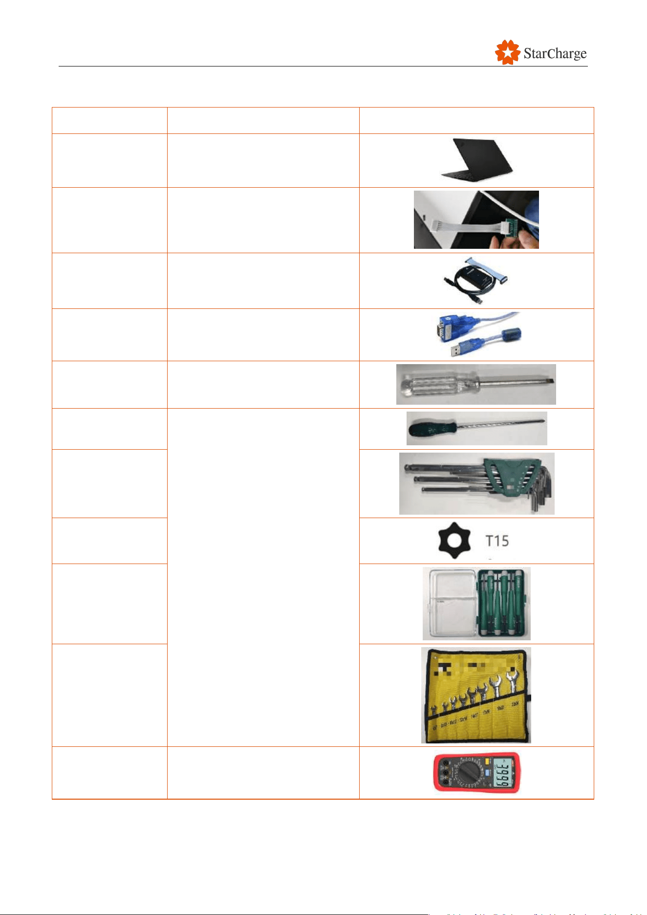
V 1.0.0 Star
97
Appendix 4 Required tools for commission
Name
Usage
Picture
Laptop
Parameter setting and intercept the
passage
P6 small line
M4 board program burning
J-LINK
Flash program
232 tool
Intercept message and flash
program
Slotted screwdriver
Fastening screws
Phillips screwdriver
Fastening screws
Allen key
T15 Torx
screwdriver
Screwdriver set
Wrench
Multimeter
Electrician measuring appliance
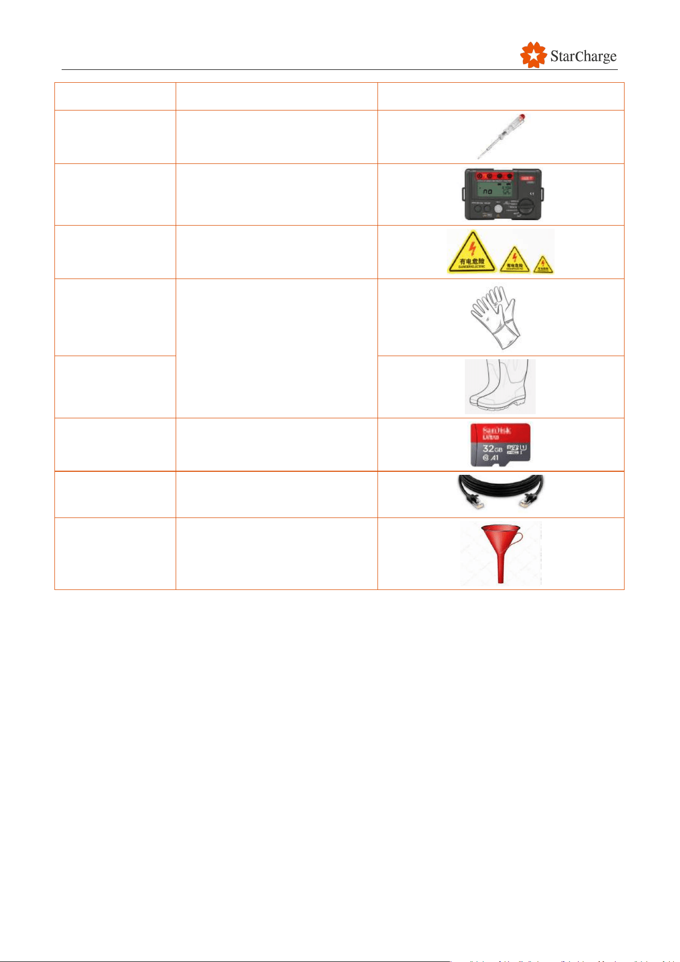
V 1.0.0 Star
98
Name
Usage
Picture
Test pencil
Electrician measuring appliance
Megohmmeter
Insulation resistance measurement
Safety signs
Safety signs
Electrician protective
gloves
Safety protective equipment
Electrician protective
rubber shoes
TF card
Update program
Ethernet cable
Web setting
Funnel (optional)
For coolant filling (non-essential,
only for low coolant level)
V 1.0.0 Star
99
7 Preventive Maintenance
All Preventive Maintenance (PM) and Corrective Maintenance (CM) activities are provided for
information only. PTOs are not required to learn or assess these activities for competency or
qualification purposes, as evaluation and qualification are handled by the OEM.
Before you start any preventive maintenance on your EVSE, make sure you have read and
understand all the safety instructions. This is important to prevent any accidents or injuries.
All preventive maintenance should be carried out by authorized technician. This is important to
ensure that the maintenance is done correctly and safely.
The specific preventive maintenance tasks that should be performed differs from the type of EVSE.
However, some common tasks include:
● Inspecting the EVSE for signs of damage or wear and tear.
● Cleaning the EVSE and its components.
● Testing the EVSE to ensure that it is functioning properly.
The following check items, as well as the frequency (per year) and working hours are based on
Chinese experience and are provided for reference. Overseas regions can adjust them according to
local requirements and actual conditions.
Items
Frequency
Working hours
Remark
External and environmental checks
Yearly
10min/site
Functionality checks and tests
10min/unit
Cleaning
10min/unit
Electrical checks and tests
15min/unit
New Electric Vehicles (EV) / e-buses
interoperability tests
10min/unit
Table 7-1 Preventive maintenance

V 1.0.0 Star
100
7.1 External and environmental checks
Requirements: EV Charger power TURN-ON at isolator. It is necessary to identify the dangerous
source of the charging site and report the hidden safety hazard.
Working hours: 10min/site
Frequency: Yearly
Content and Specification
Check
Method
Conclusion
Remark
Installed outside hazardous zones where flammable or
combustible gas or material may be presented
Visual
□ Pass □ Fail
Enclosure is not dented, damaged, corroded or in any rusty
condition.
Visual
□ Pass □ Fail
Space around the EV Charger is adequate for easy access
and maintenance work.
Visual
□
Pass
□
Fail
Sealing rubber of all doors are in order, and doors including
lockset (if any) can be opened and closed easily.
Visual
□ Pass □ Fail
No sign of insects inside EV Charger. Openings or vents are
not blocked, no excess foreign particles.
Visual
□ Pass □ Fail
Detachable parts are not loose or falling off and not in a
rusty condition.
Visual
□
Pass
□
Fail
No visible moisture, waterlogging or burnt marks at the EV
Charger and connector charging pins.
Visual
□ Pass □ Fail
Floor or wall mounting of EV Charger remains rigid and
strong.
Visual
□ Pass □ Fail
Vehicle connector cable, mounting and support is secured
and not damaged.
Visual
□
Pass
□
Fail
Electrical warning labels is clear and prominent.
Visual
□ Pass □ Fail
Source of Distribution Box (DB) for EV Charger is clearly
labelled and electrical source DB is accessible for operation.
Visual
□ Pass □ Fail
Bollards or continuous kerb(s) or other means of crash
protection is installed to provide adequate protection
against moving vehicles.
Visual
□
Pass
□
Fail
Charger specification plate is clear, legible, and prominent
according local requirement.
Visual
□ Pass □ Fail

V 1.0.0 Star
101
RRP or Operator of EVSE's contact details label is legible
and prominent
Visual
□
Pass
□
Fail
Fail-safe emergency stop button (in red and yellow) is
prominent and not damaged. For outdoor installation it shall
be weatherproof. Clear directional signs shall be provided
for multiple charger installations.
Visual
□
Pass
□
Fail
Adequate lighting for charging operation.
Visual
□ Pass □ Fail
EV Charger's touchscreen and all User Interface
accessories (e.g. press button, RFID reader etc.) are not
damaged and are working properly.
Manually
□
Pass
□
Fail
Incoming power supply cable including circuit protective
conductor connections and termination(s) are properly
made and tightened.
Visual
□
Pass
□
Fail
Measurement of Proximity Pin -Protective Earth resistance
value and to be compared with the given value in the IEC
Standard.
PP-PE:
(Ohm)
□ Pass □ Fail
Equipped with fire extinguishers and other safety facilities.
Safety facilities are available.
Visual
□
Pass
□
Fail
The nameplate is complete, correct, and firm.
Visual
□
Pass
□
Fail
The fireproof mud or sealing boards is complete, correct,
and firm
Visual
□ Pass □ Fail
The door cannot be opened when it is properly closed and
locked.
Visual
□
Pass
□
Fail
No water leakage, condensation, rust or damage inside the
EVSE
Visual
□
Pass
□
Fail
Table 7-2 External and environmental checks

V 1.0.0 Star
102
7.2 Functionality checks and tests
Requirements: EV Charger power TURN-ON at isolator.
Working hours: 10min/unit
Frequency: Yearly
Content and Specification
Check Method
Conclusion
Remark
Perform the sequence of normal start and stop on
every charging point.
Manually
□ Pass □ Fail
While charging, check EV ventilation fan (if any) is
working.
Manually
□
Pass
□
Fail
While charging, test all the fail-safe emergency stop
button(s) to ensure it is functioning. (EVSE shall
reset to state A upon releasing)
Manually
□ Pass □ Fail
Perform control pilot short fault simulation for every
charging point. (EV Charger shall reset to state A
upon releasing)
Manually
□ Pass □ Fail
Door interlock test - Open respective door of the
charger and all its peripherals and the system shall
show that the charger is unavailable.
Manually
□
Pass
□
Fail
Emergency stop check - Start charging the EV,
press open one of the doors during charging. Did
the charge session stop immediately and did the
system display an error screen.
Manually
□ Pass □ Fail
Surge protection device - Test/Confirm that
protection is still active and available.
Manually
□ Pass □ Fail
Verify that all connections of CCS cables are
tightened.
Manually
□
Pass
□
Fail
All LED indicators work normally
Visual
□ Pass □ Fail
The HMI touchscreen displays normally, and touch
function is workable.
Visual
□ Pass □ Fail
Corresponding DC output contactor ought to be
connected or disconnected when you configure in
web panel.
Web Debug
mode
□
Pass
□
Fail
Table 7-3 Functionality checks and tests

V 1.0.0 Star
103
7.3 Charging connector inspection
Requirements: EVSE should be turned off.
Working hours: 20min/unit
Frequency: Yearly (Based on real situation)
Content and Specification
Check Method
Conclusion
Remark
Check if there is any damaged or burning parts on
the charging connectors. If yes, please replace
connector cable immediately.
Manually
□ Pass □ Fail
Check if there are any foreign particles or water
stains in the charging connector head. If yes, take
out the foreign particle with a stick shaped object
to make sure the interior of the connector head is
clean and tidy.
Manually
□ Pass □ Fail
Check whether the spring inside the gun head is
deformed or hot melted. If yes, please replace
connector cable immediately.
Manually
□
Pass
□
Fail
Check whether the cable of the charging
connector is wrinkled, cracked, and whether the
cable at the end of the connector has sheathing
off , If yes, please replace connector cable
immediately.
Manually
□
Pass
□
Fail
Check whether the waterproof rubber pad of the
connector head has potential water leakage
caused by cracking , If yes, please replace
connector cable immediately.
Manually
□
Pass
□
Fail
Check whether the connector head fixing screw is
missing or loose, if so, tighten the screw before
use.
Manually
□ Pass □ Fail
Table 7-4 Charging connector inspection
V 1.0.0 Star
104
7.4 Electrical checks and tests
Requirements: To be performed by skilled person
Working hours: 20min/unit
Frequency: Yearly
Content and Specification
Check Method
Conclusion
Remark
Record the incoming power supply and charging
cable insulation resistance value is more than 10M
ohm.
Manually
□ Pass □ Fail
Rating of incoming cable from source DB & charging
cable are adequate for maximum rated charging
current.
Manually
□
Pass
□
Fail
Perform earth loon impedance test and record value
(< 0.1 ohm)
Manually
□ Pass □ Fail
Table 7-5 Electrical checks and tests
7.5 New Electric Vehicles (EV) / e-buses interoperability tests
Requirements: EVSE should be turned on.
Working hours: 15min/unit
Frequency: Yearly
Table 7-6 New Electric Vehicles (EV) / e-buses interoperability tests
Content and Specification
Check Method
Conclusion
Remark
Interoperability coordination meetings
Manually
□ Pass □ Fail
Interoperability test
Manually
□ Pass □ Fail
Interoperability issue handling and solution
Manually
□
Pass
□
Fail

V 1.0.0 Star
105
7.6 Charging test
Once you have completed all of the required checks above, refer to the user manual and do the
following steps:
Use the designated app or scan the QR code or swipe the card to start the charging process.
If the charging process is successful, then your EVSE is working properly. If you have any problems,
please contact the manufacturer or a authorized technician.
EV Model
CPID
Required
Voltage (V)
Required
Current (A)
Output
Voltage (V)
Output
Current (A)
Conclusion
□ Pass □ Fail
□ Pass □ Fail
□
Pass
□
Fail
□
Pass
□
Fail
□
Pass
□
Fail
□ Pass □ Fail
□ Pass □ Fail
□ Pass □ Fail
□
Pass
□
Fail
□
Pass
□
Fail
Table 7-7 Charging test
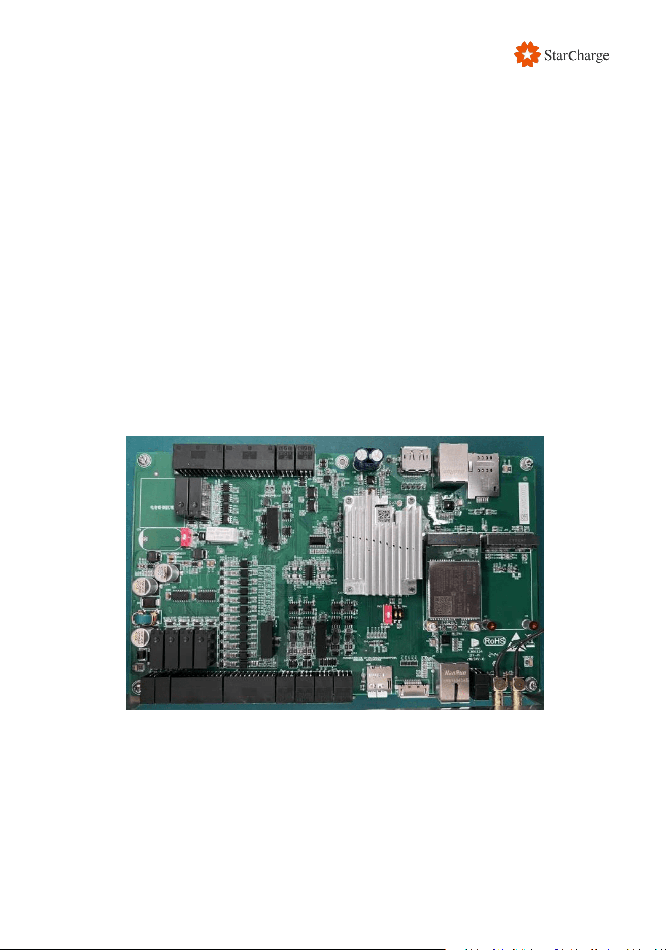
V 1.0.0 Star
106
8 Corrective Maintenance
8.1 Could not access web panel
Issue: Could not access web panel.
Possible causes:
● Enter the wrong website address.
● The IP address of the laptop is not configured correctly.
● The network connection of the network cable is unstable.
● There is hardware issue with the AM62 board or switch.
Solution:
(1) Check the IP address setting of the laptop.
(2) Check the connection of the network cable.
(3) Check if the network cable or the laptop is normal.
(4) Try to change a browser (Edge and Chrome are recommended) and clear the cache.
(5) Use SD card to upgrade AM62 board again.
(6) Try to replace the AM62 board.
Figure 8-1 The AM62 core board and the AM62 board
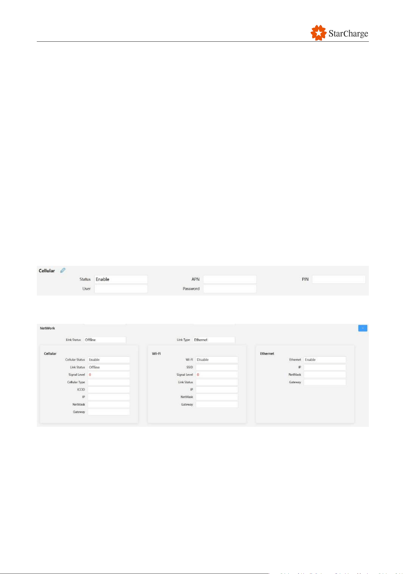
V 1.0.0 Star
107
8.2 No network connection
Issue: EVSE is offline on the web panel in Network State.
Possible causes:
● The SIM card is not correctly inserted.
● Incorrect APN configuration.
● Unstable 4G signal.
● SIM card is out of charge.
● Non-supported frequency band.
● Unstable Wi-Fi signal.
● Unstable network connection.
● The 4G communication module or the AM62 board is faulty.
Solution:
● If the EVSE is connected to the network by SIM card:
(1) Power off and check whether the SIM card is correctly inserted. Reboot the system if inserting
the SIM card while the EVSE is power on.
(2) Check whether the SIM card is workable and whether the configurations in the web panel are
correct.
Figure 8-2 Configure parameters of the SIM card
(3) Check “Strength of 4G” in web panel. (If CSQ<18, the site signal is not stable)
Figure 8-3 Network state
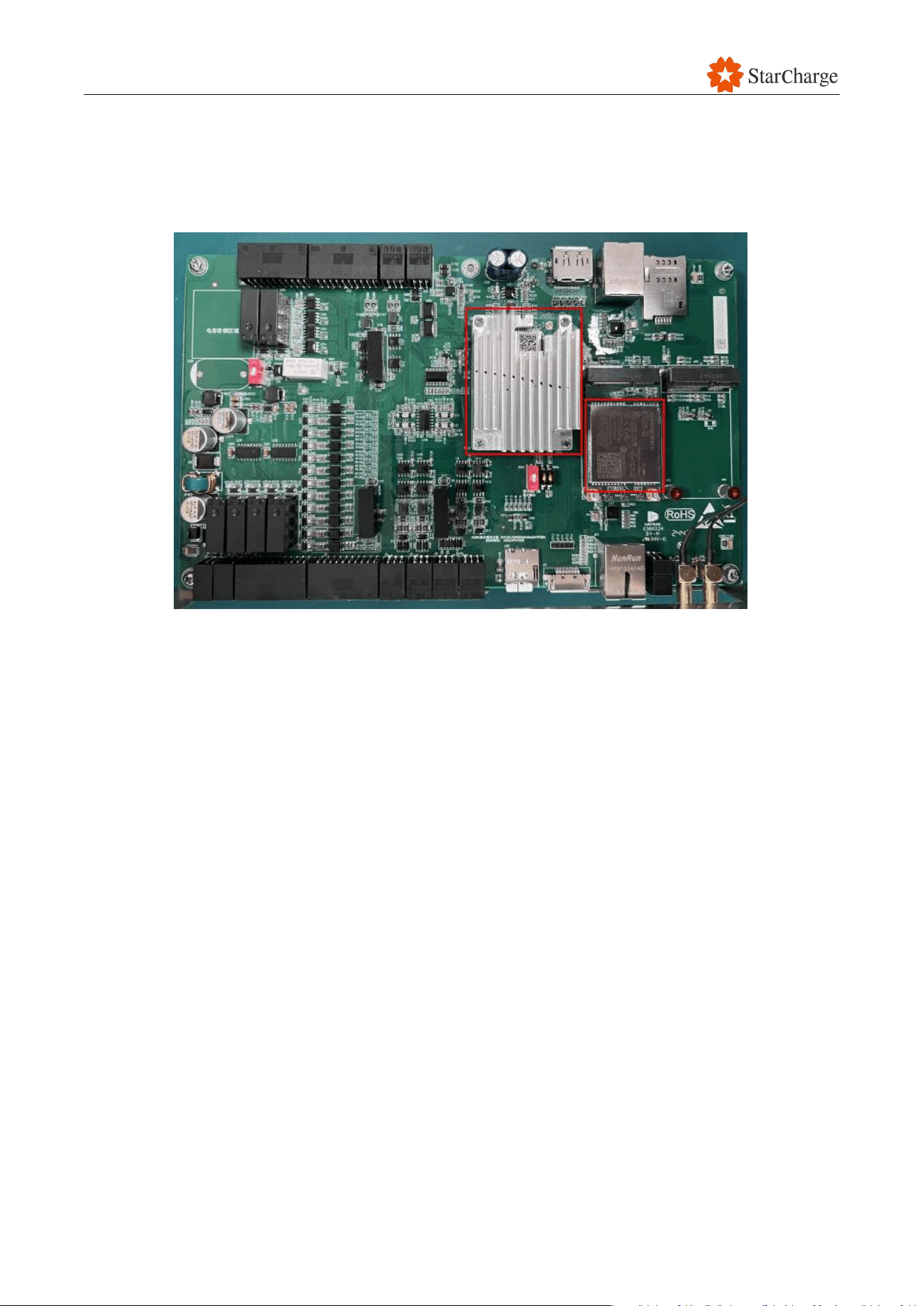
V 1.0.0 Star
108
● If the EVSE is connected to the network by Wi-Fi or by Ethernet:
(1) Connect your mobile phone to this Wi-Fi or connect the network cable to your laptop to check
whether it is connected to the network.
(2) Try to replace the 4G communication board or the AM62 board.
Figure 8-4 The location of the AM62 core board and the 4G communication board
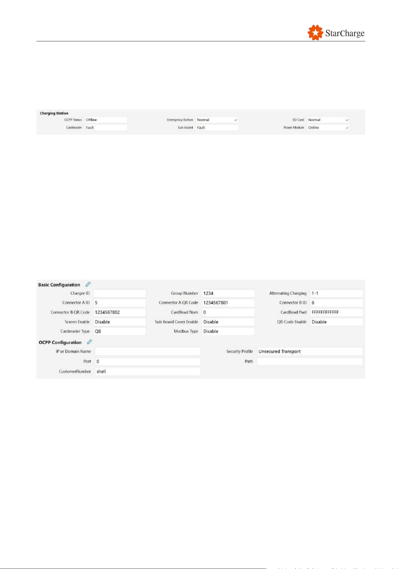
V 1.0.0 Star
109
8.3 EVSE is offline
Issue:
● EVSE is offline in the backend.
● OCPP status is Offline in the web panel.
Figure 8-5 Status of OCPP
Possible causes:
● The EVSE lost power.
● The EVSE is not connected to the network successfully.
● Configurations are not set correctly in the web panel or the backend.
● The 4G communication module or the AM62 board is faulty.
Solution:
(1) Check whether the EVSE is power-on. If not, check whether there is power.
(2) Check the network connection.
(3) Check the OCPP backend and the ID configuration in the web panel.
(4) Check charger status in OCPP backend, confirm the OCPP backend is normal.
Figure 8-6 Configurations of CPID and OCPP
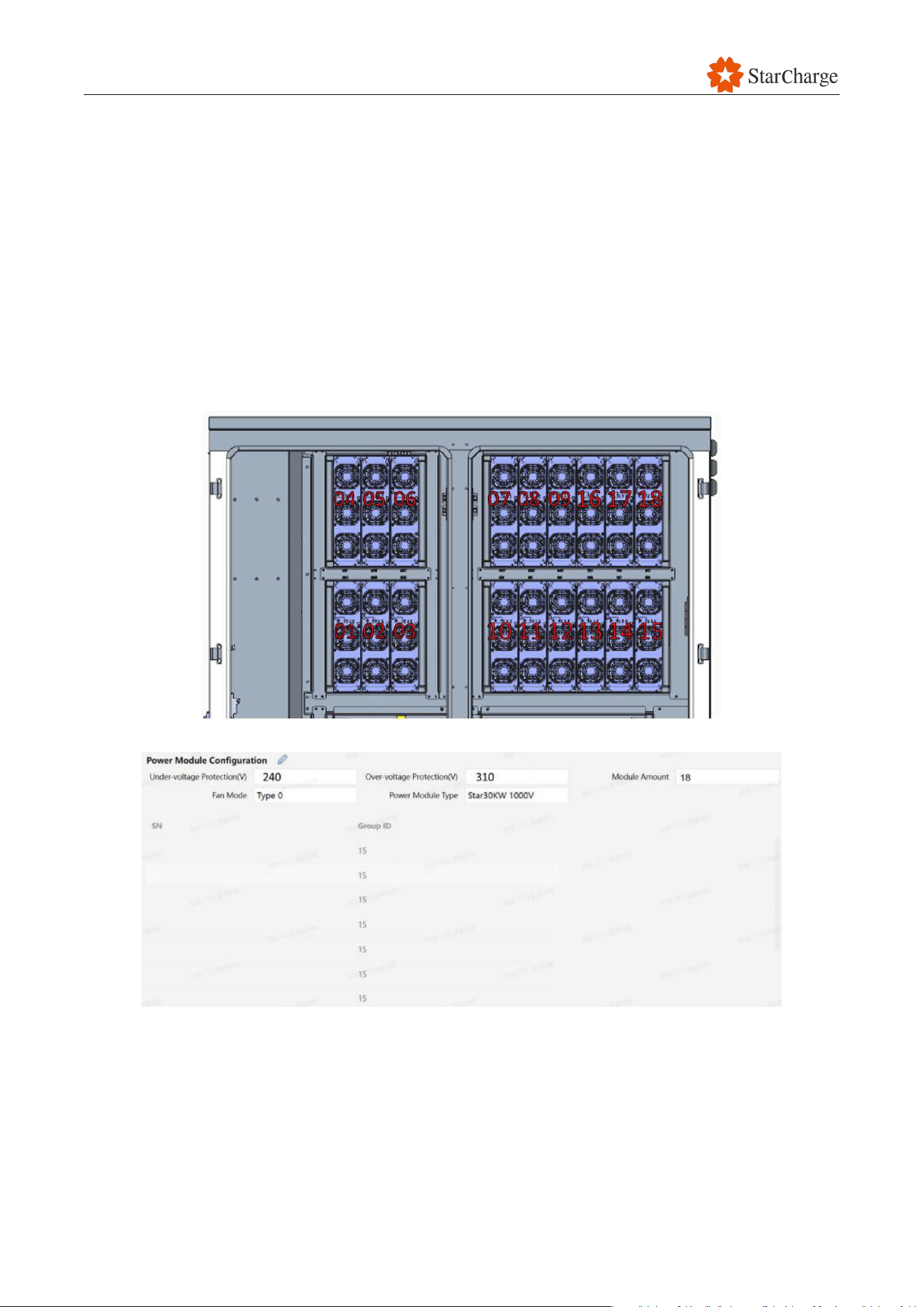
V 1.0.0 Star
110
8.4 Power module communication fault
Issue: Power module communication fault
Possible causes:
● The power module or the power module socket is faulty.
● The MCCB is faulty or tripped.
● The AC contactor is faulty.
● The power module address is not set correctly.
● Power module configurations are wrong.
Solution:
(1) Check the power module addresses and configurations in the web panel.
Figure 8-7 Addresses of the power module
Figure 8-8 Configure the power modules in the web panel

V 1.0.0 Star
111
(2) Check whether some of the power module fault light is on. Follow the checklist below to check.
Indicator light
Status
Status description
Solutions
Alarm
indicator
(Yellow)
On
• Power derates due to
missing phrase of AC input
and temperature
• Irregular current sharing
Check if the input wiring and
power distribution switch of the
charger or the charging stack
cabinet are normal.
If the input wiring and power
distribution switch of the charger
or the charging stack cabinet are
normal, but the alarm still exists,
replace it
Flashing
Operating under manual mode
Contact your dealer or service
team for help
Alarm
indicator (Red)
On
• EEPROM fault
• Fan drive fault
• AC Input over/ under voltage
• Missing phrase for AC input
• Over temperature inside
• Irregular communication for
primary and secondary side
• Output over/under voltage
• AC over voltage separation
• Serial number duplication
Replace the power module
Flashing
Fans don’t work
Contact your dealer or service
team for help
Table 8-1 Power module fault light checklist
(3) Measure the input voltage of the EVSE. If abnormal, contact the installation team to check.
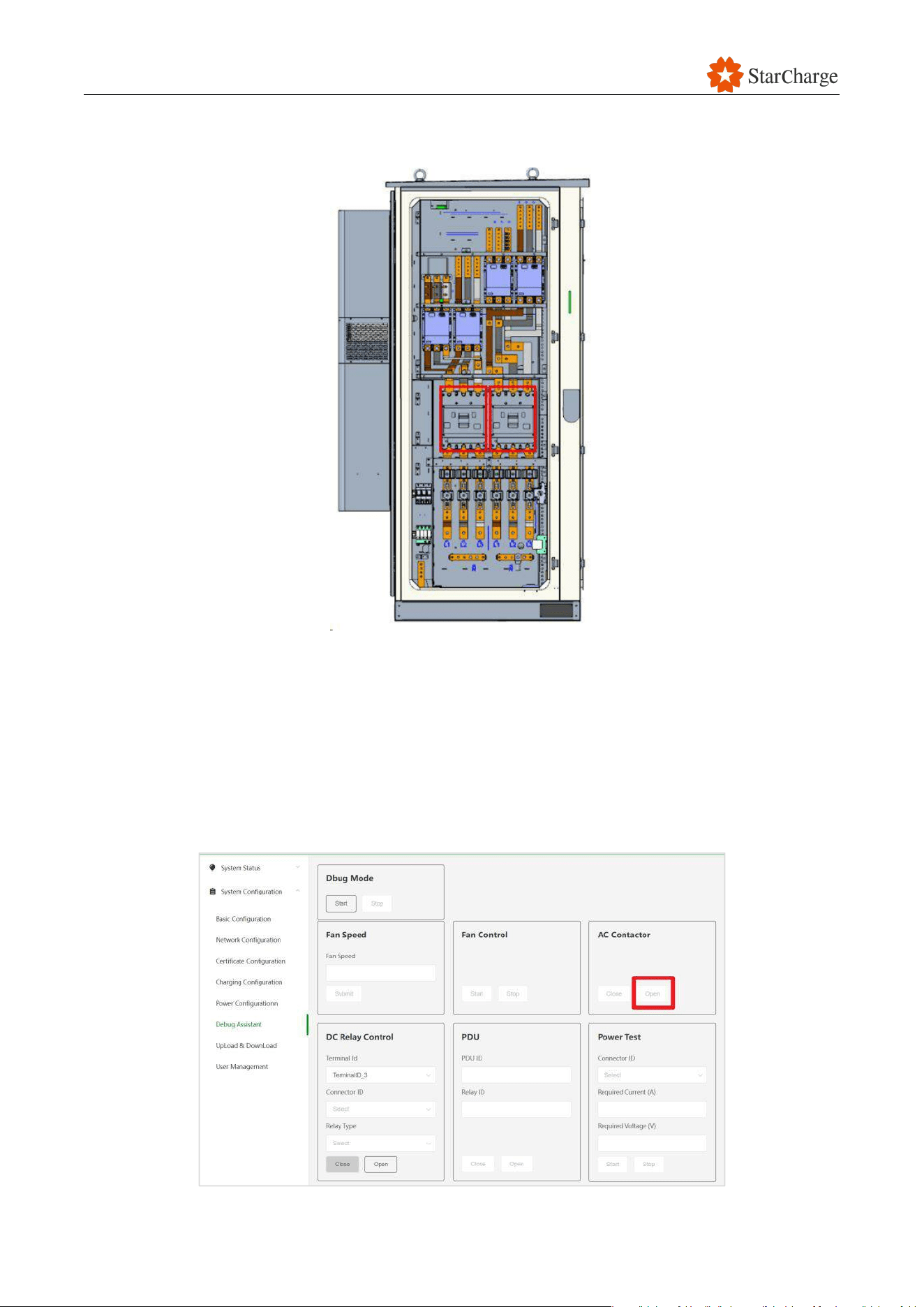
V 1.0.0 Star
112
(4) If the input power is normal, check whether the MCCB is tripped. If so, turn it on. If not, measure
the input and output voltage ( AC 480V) of the MCCB. If there is no output, replace the MCCB.
Figure 8-9 MCCBs of the EVSE
(5) If the MCCB is normal, close the AC contactor in web panel (disable the door sensor and close
the AC contactor). Measure the input and output voltage of each AC contactor (AC 4800V). If
there is no output in each AC contactor, check the AC contactor control signal first; If one AC
contactor does not have output voltage, measure whether there is 480V to the AC contactor . If
so, check the control loop of the AC contactor, If the control loop is normal, replace the AC
contactor.
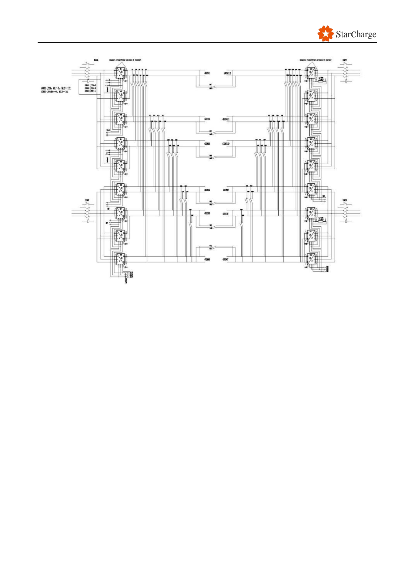
V 1.0.0 Star
113
Figure 8-10 Configurations for the AC contactor in web panel
(6) If the AC contactor is normal, turn on the AC contactor in the web panel. Check the status of
power modules in web panel. If the status of one of the power modules is offline, plug in this
power module one more time or swap it with another power module. If the same power
module remains offline, replace the faulty power module.
(7) If not, measure the resistance between CANL and CANH of the power module socket, the
normal resistance is 60Ω. If abnormal, remove the J23 port on AM62 board (CB01)
(8) If modules at addresses 1/3/7/9/13/15/16/18 lose connection, measure the resistance between
CANL and CANH of power module socket, the normal resistance is 120Ω. If abnormal, replace
the 120Ω resistor on the power module socket. Measure the resistance between 1&4 pin of J23
port on AM62 board, the normal resistance is 120Ω. If abnormal, replace the AM62 board.
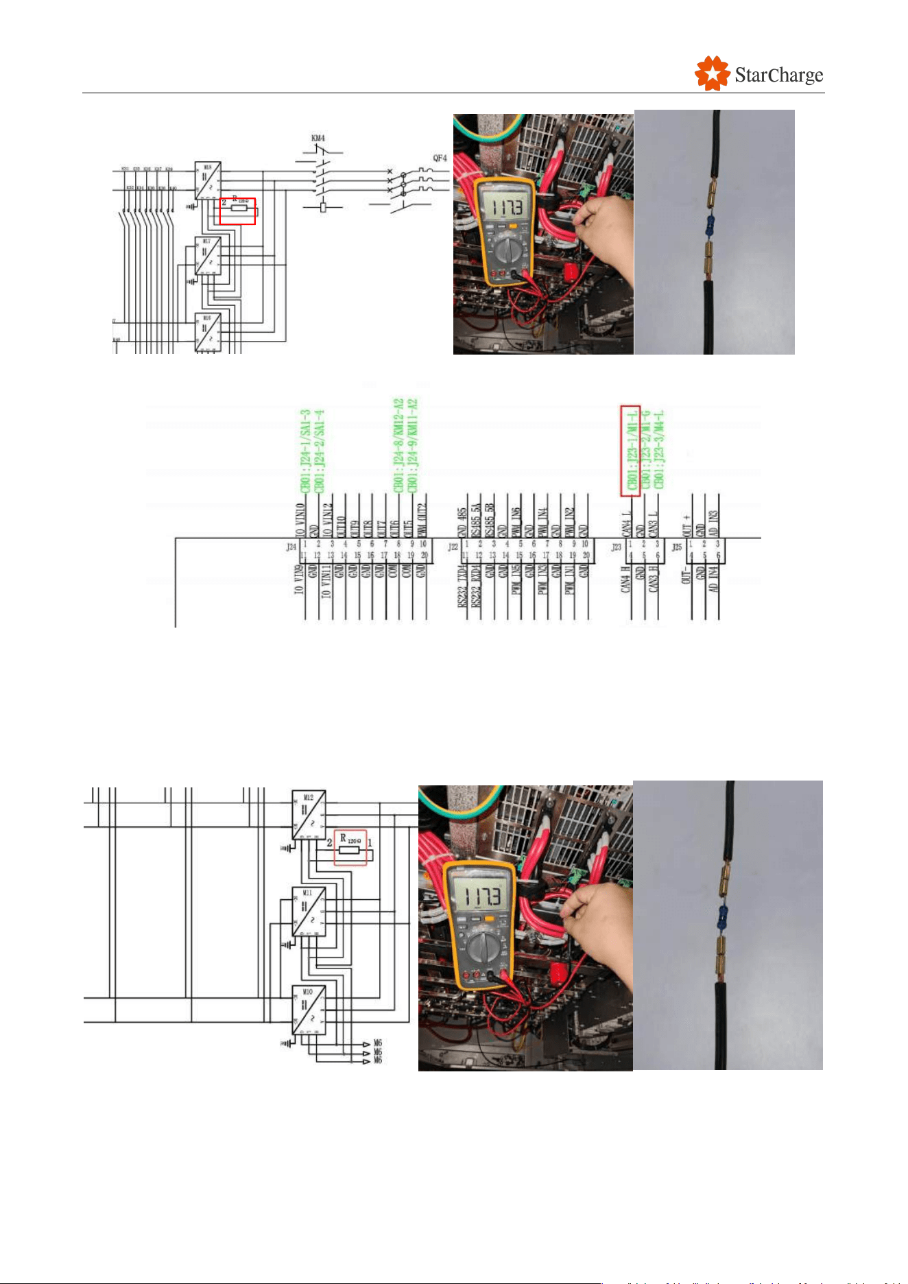
V 1.0.0 Star
114
Figure 8-11 Measure the resistance
Figure 8-12 Power communication port on the mainboard
(9) If modules at addresses 4/6/10/12 lose connection, measure the resistance between CANL
and CANH of power module socket, the normal resistance is 120Ω. If abnormal, replace the
120Ω resistor on the power module socket. Measure the resistance between 3&6 pin of J23
port on AM62 board, the normal resistance is 120Ω. If abnormal, replace the AM62 board.
Figure 8-13 Measure the resistance
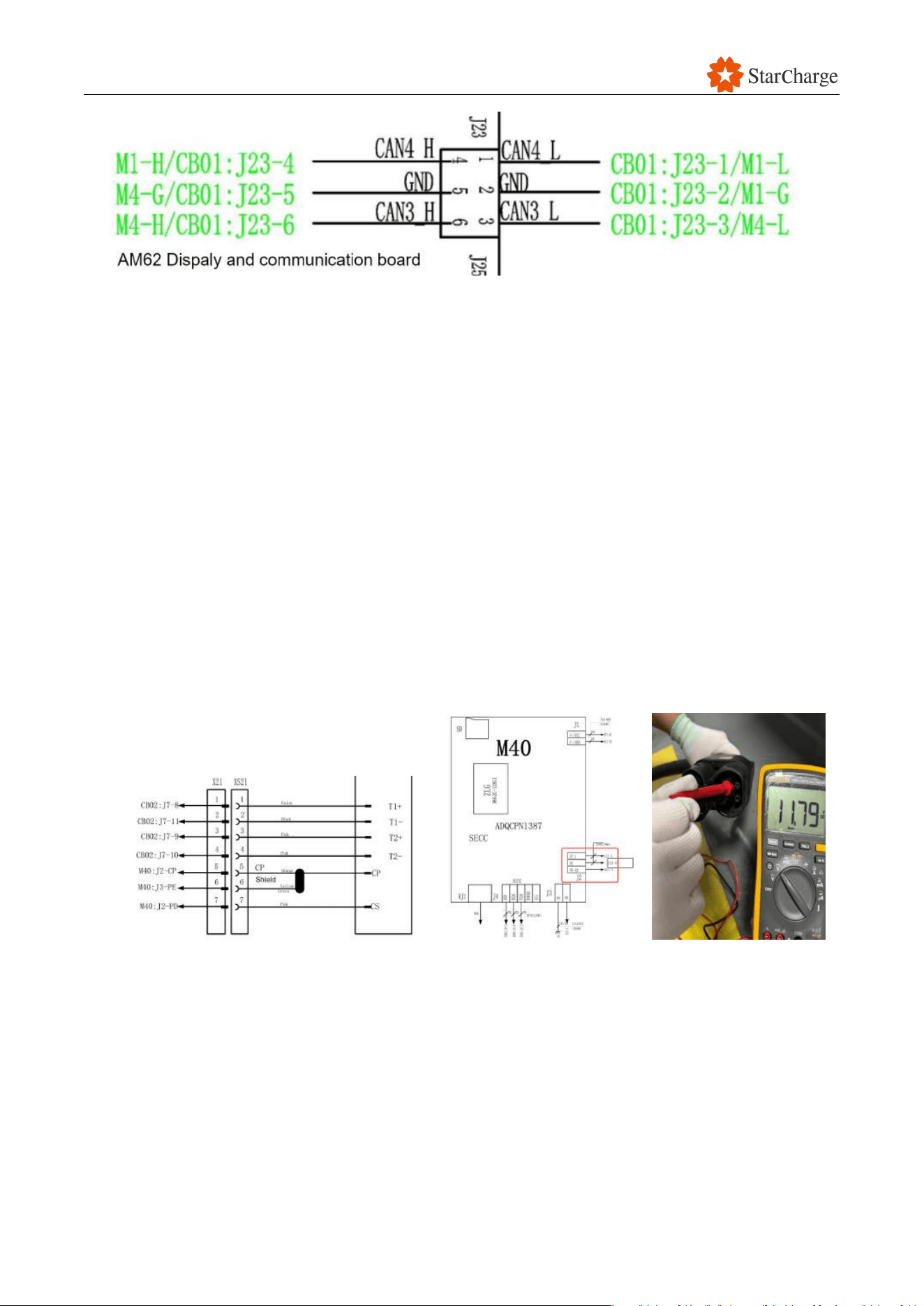
V 1.0.0 Star
115
Figure 8-14 Power communication port on the mainboard
8.5 No response after plug in
Phenomenon: No response after plug in the charging connector
Possible causes:
● Charging connector faulty.
● Abnormal CP voltage.
● Abnormal wire connection of the SECC board.
Solution:
(1) Check whether there is water, stone, or foreign materials inside the charging connector head. If
so, clean or dry it.
(2) Measure the voltage between CP and PE when the charging connector is not plugged in, the
normal voltage is 12V. Measure the voltage between CP and PE inside of the EVSE when plug
in the charging connector into the EV, the normal voltage is 9V. If the voltage is abnormal,
check the wiring on the SECC board. Correct it or replace the SECC board.
Figure 8-15 Measure the voltage between CP and PE
(3) Measure the resistance between PP and PE, the normal resistance is 1.45kΩ. If abnormal,
replace the charging connector.
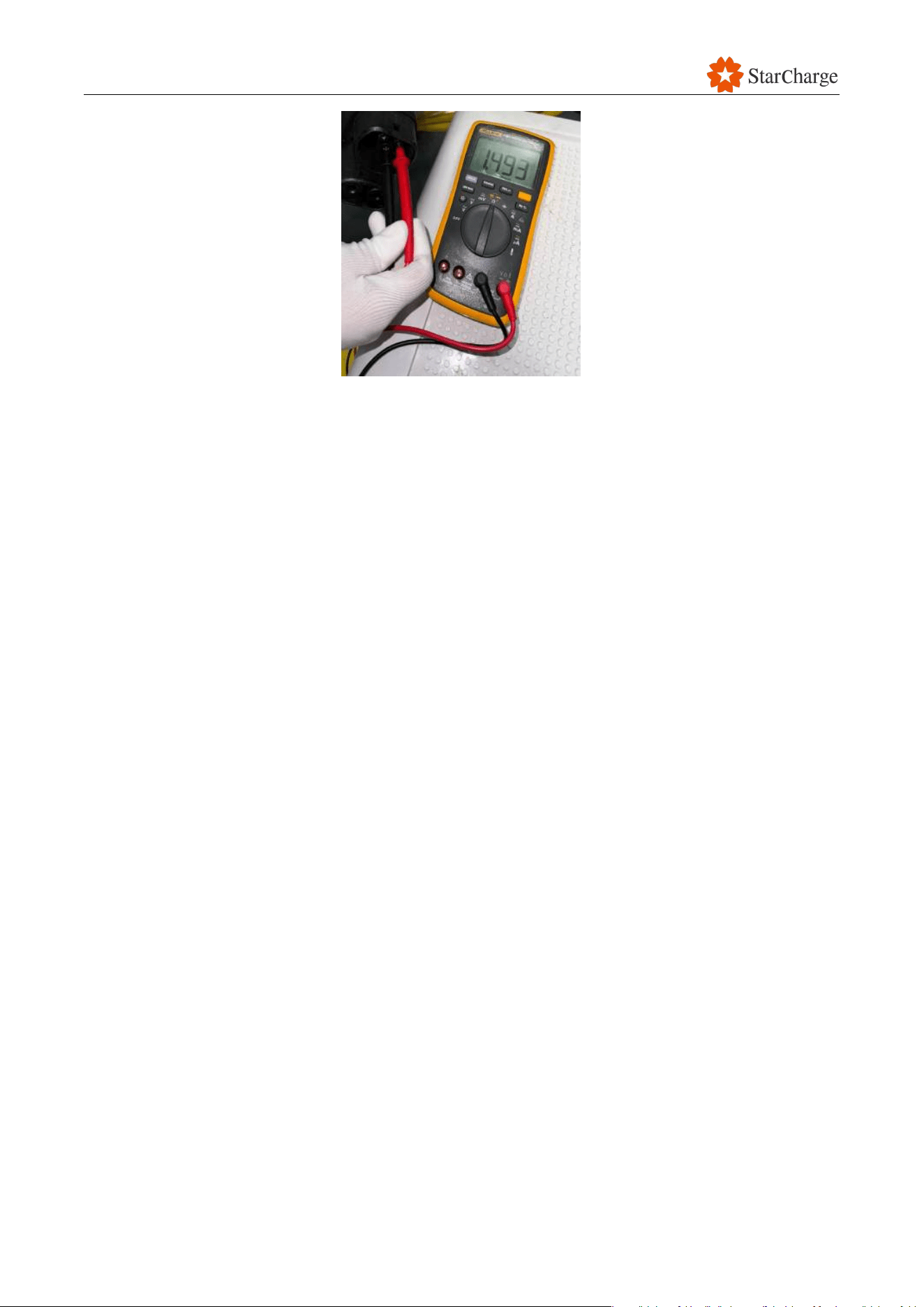
V 1.0.0 Star
116
Figure 8-16 Measure the voltage between PE and PP
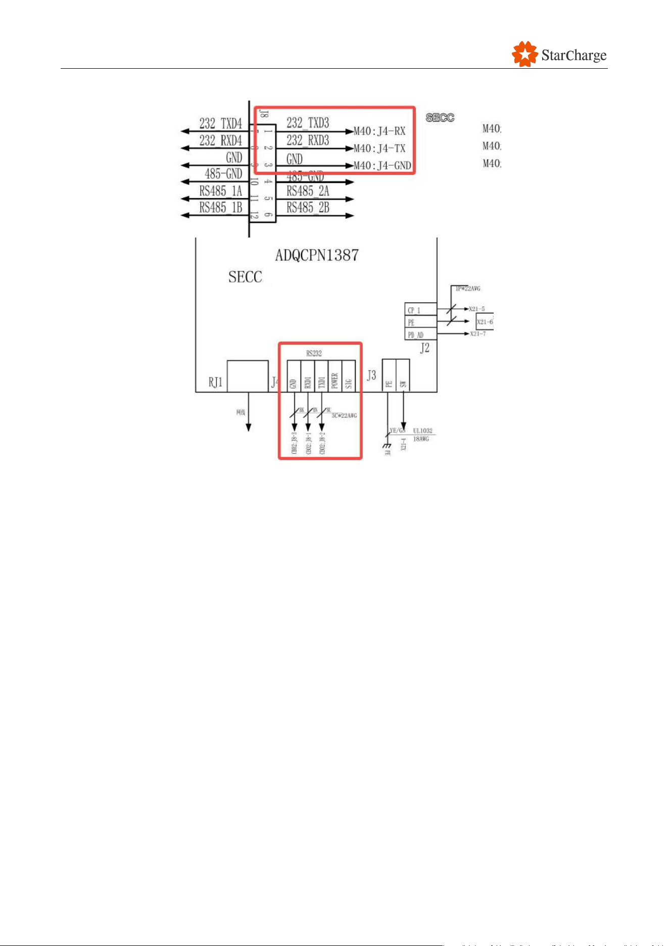
V 1.0.0 Star
117
(4) Check the wiring between the SECC board and the M4 board (CB02)..
Figure 8-17 Wiring between the SECC board and the M4 board (CB02)
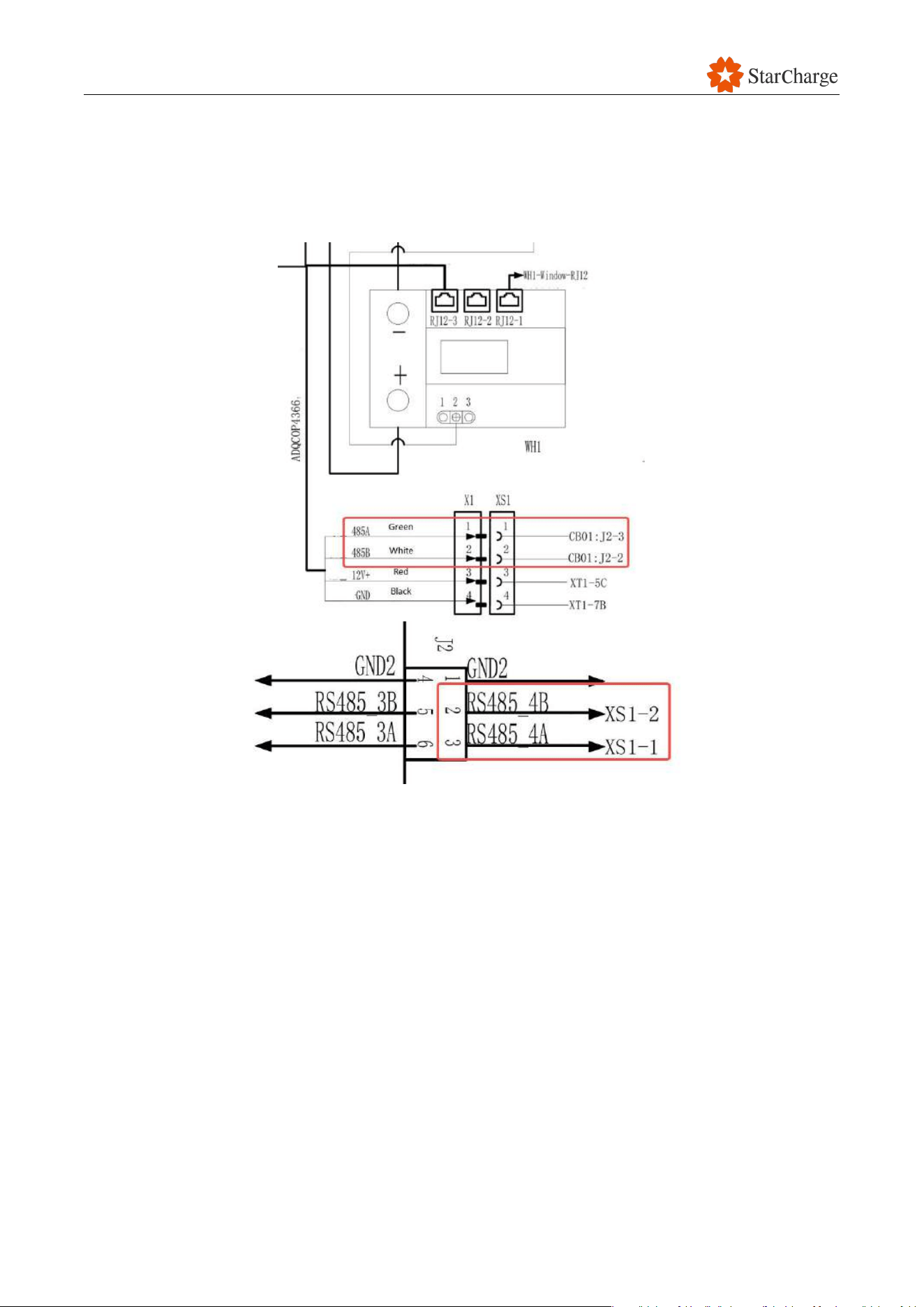
V 1.0.0 Star
118
8.6 Meter communication failure
Phenomenon: Meter communication light is off, and the LED indicator is always red.
Possible cause: The RS485 communication between the AM62 board (CB01) and the DC Meter is
abnormal.
Figure 8-18 RS485 communication between the AM62 board (CB01) and the meter
Solution:
(1) Use a multimeter to check the circuit of the AM62 board (CB01) 485 communication ports A
and B corresponding to the A and B interface of the meter. If there is anything abnormal,
replace the communication wire or correct the wiring.
(2) Check the meter communication logs to identify the problem, and replace the faulty
components as needed.
Note: If the issue persists even after following these steps, please contact the customer service for
further assistance.

V 1.0.0 Star
119
8.7 Input under-voltage fault
Possible causes:
● The input voltage is over 480V-10%.
● The power module is faulty.
Solution:
(1) Measure the input voltage of the EVSE, if abnormal, contact the installation team.
(2) Monitor whether there are any errors with the power modules during charging. If so, replace
the faulty power module.
8.8 Input over-voltage fault
Possible causes:
● The input voltage is over 480V+10%.
● The power module is faulty.
Solution:
(1) Measure the input voltage of the EVSE, if abnormal, contact the installation team.
(2) Monitor whether there are any errors with the power modules during charging. If so, replace
the faulty power module.
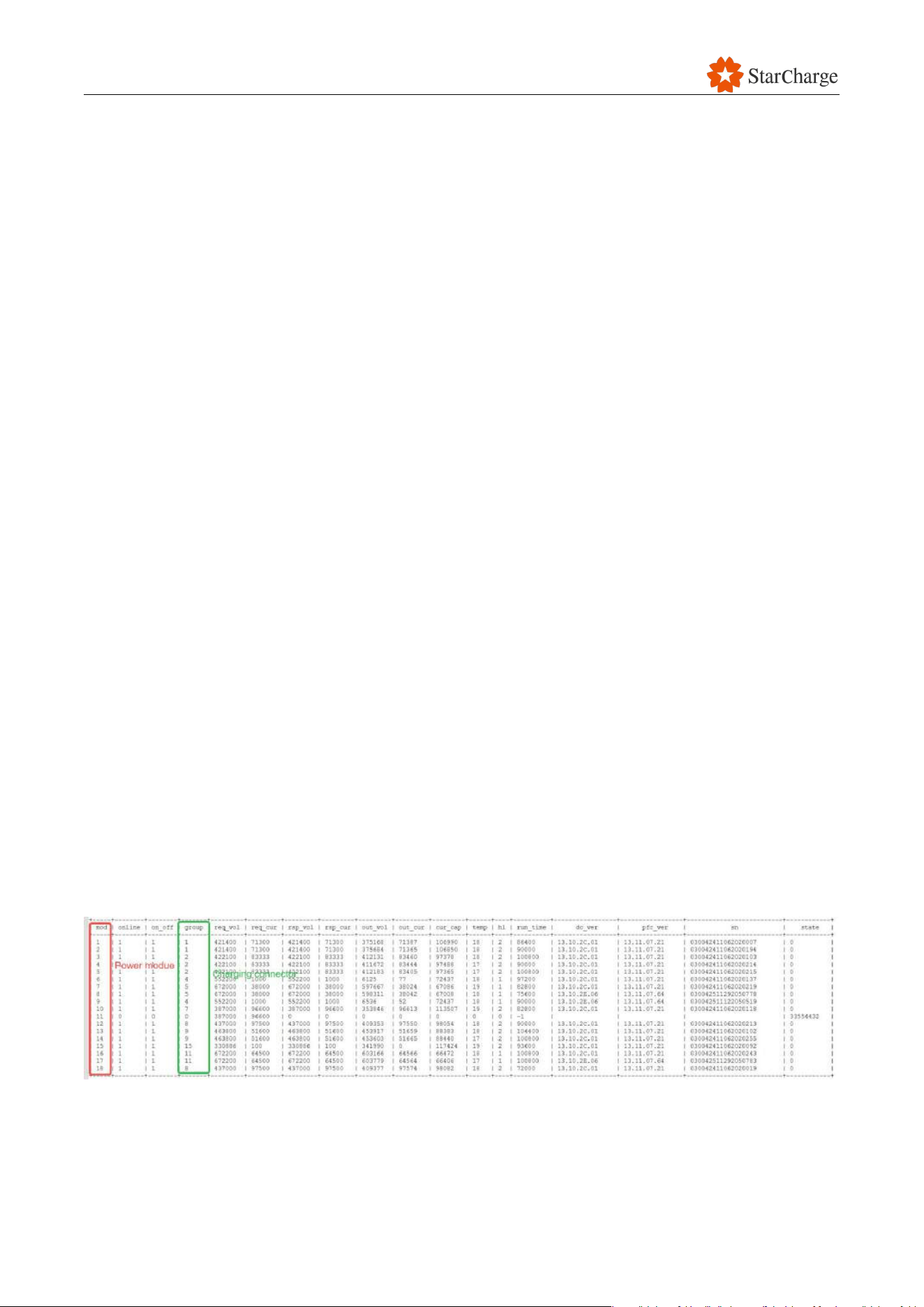
V 1.0.0 Star
120
8.9 Insulation fault
Possible causes:
● The wires between M4 board and Copper busbar are loosen or faulty
● The M4 Board is faulty
● The power model is faulty
● The insulation resistance of the charging connector is less than 100Ω/V
● The insulation resistance of the DC cable which between power cabinet and user unit is less
than 100Ω/V
● Electric vehicles faulty with insulation issues.
Solution:
Please power off the power cabinet and user unit before testing the insulation value.
● If only one charging connector reports the insulation fault regularly.
(1) Check the wires between M4 board and Copper busbar, make sure all the wires are properly
connected.
(2) Replace with a new M4 board and test charging again.
(3) Remove the charging connector from the copper busbar. Check the insulation value between
charging connector DC positive cable (DC negative cable) and PE with the megohmmeter. If
the insulation value is less than 100Ω, please replace the charger connector.
(4) Check the insulation value between the DC input cable to PE inside the user unit. If the
insulation value is less than 100Ω/V,please consider the cable is faulty and contact the
installer.
● If multiple charging connector A / connector B from different user units are reporting insulation
fault and they are connected to same power cabinet. Please consider the power model is faulty.
(1) Analysis the power cabinet log to check whether it report insulation fault when the specific
power module is used. If yes, please replace the power module.
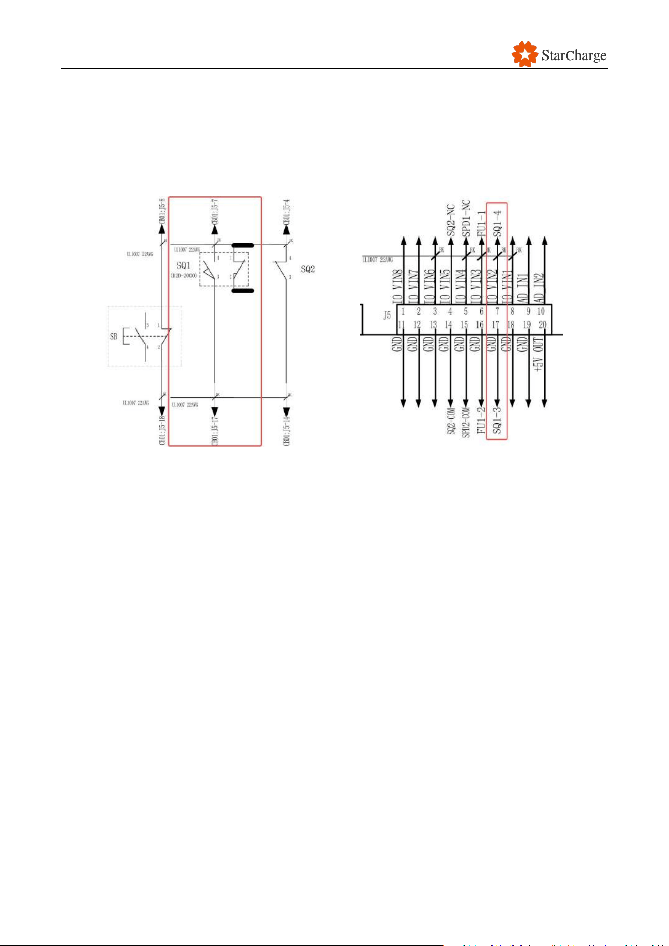
V 1.0.0 Star
121
8.10 User unit door is open
Solution:
(1) Check if the door is open.
(2) Inspect the door switch circuit for abnormalities, such as fault connections or abnormal
terminal ports. If any issues are found, rectify the wiring or replace the AM62 board.
Figure 8-19 Circuit of the door switch
(3) Manually close the door switch to check if its function is normal.
(4) Adjust the switch position in case the door does not touch the switch properly when closed.
(5) Use a multimeter to check if the door switches can properly close. If any issues are found,
replace the door switch.
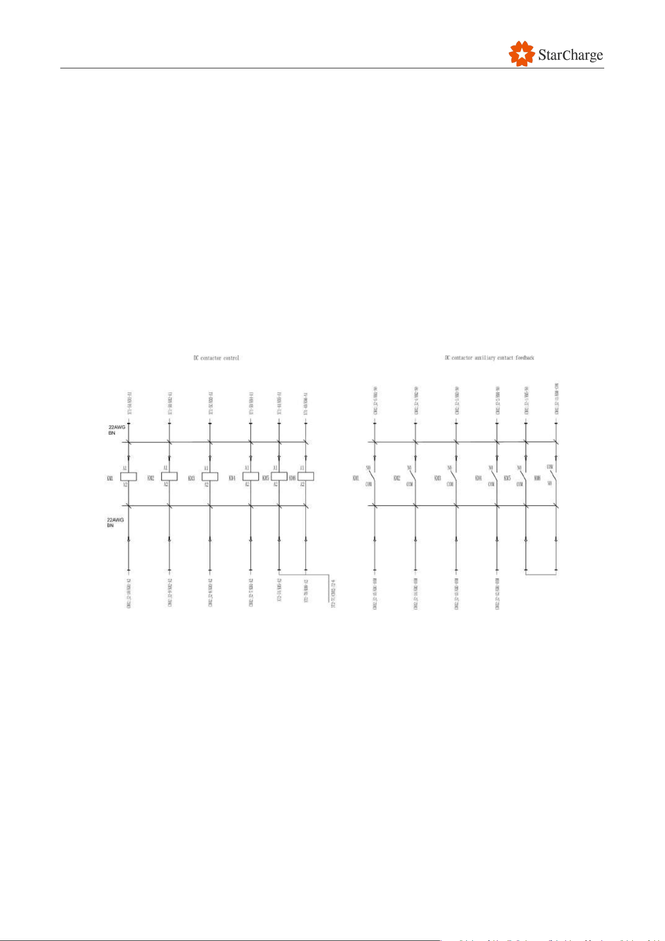
V 1.0.0 Star
122
8.11 No effective current output
Phenomenon: The charger is receiving the required voltage and current, but there is no output
current of the charging connector.
Possible causes:
● The output contactor is faulty.
● The circuit is abnormal.
● The fuse protector is faulty.
● The power module is faulty.
● The charging connector is faulty
● There is an issue with the EV.
Solution:
(1) Check whether the DC contactor circuit is correct. Verify if there is a signal in the contactor coil
control line after starting. If there is no signal, change the circuit to the correct one.
Figure 8-20 Circuit diagram DC contactor control
(2) Use a multimeter to measure whether the two sides of the DC contactor are conducting after
receiving the pull-in signal. If not, replace the DC contactor.
(3) Use a multimeter to check whether the fuse is conducting. If not, replace the fuse.
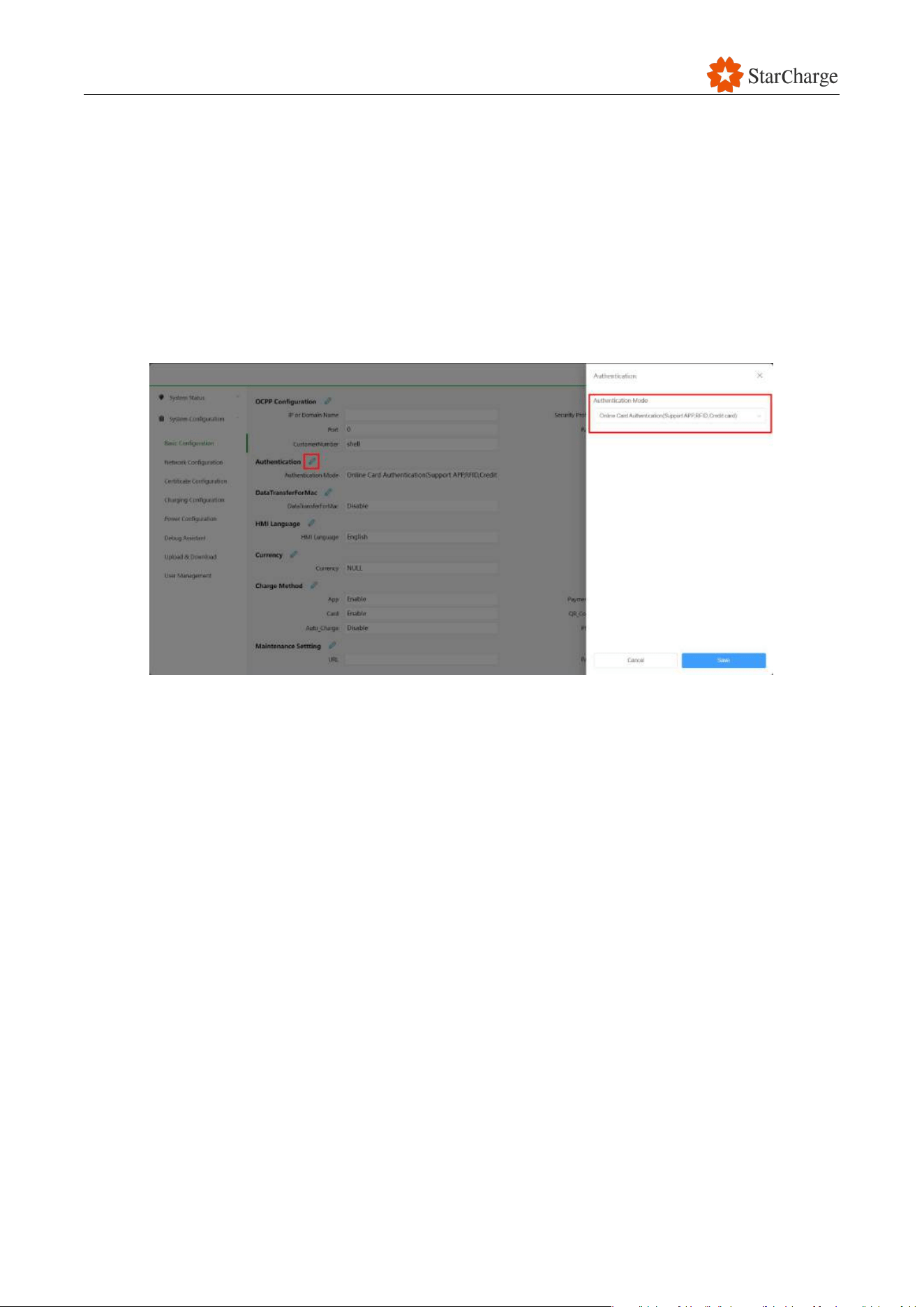
V 1.0.0 Star
123
8.12 No response after swiping a card
Possible causes:
● Wrong configuration.
● UID of the RFID card is not uploaded in the backend.
● Incompatible format of the card.
● The card reader is faulty.
Solution:
(1) Check the configuration in the web panel.
Figure 8-21 Authentication method in the web panel
(2) If EVSE is set in “Backend Authentication” mode, make sure the UID of the RFID card is
uploaded in the backend by the backend supplier.
(3) Swipe the RFID card on the card reader for 2 seconds and then remove it.
(4) Replace the RFID card reader.
(5) If the issue still exists, send the log file and the specification of the RFID card to StarCharge for
analysis.

V 1.0.0 Star
124
8.13 Cannot reach the maximum output capacity
Solution:
(1) During the charging process, check the details of the power modules and verify if the indicator
lights of the power modules are normal. Replace new power module if faulty.
(2) Check the parameter settings and ensure that the maximum output voltage and the current
are set correctly.
8.14 Cooling fan malfunction
Possible causes: The cooling fan does not work during charging, resulting in abnormal heat
dissipation and a decrease in charging current.
Solution:
(1) Check whether the power line of the fan is loose, short-circuited, or open-circuited. If any
abnormalities are found, rectify the wiring.
(2) Check if the power supply to the fan is normal. If the power supply is abnormal, check the
connection of the environment board port or related control relays. If needed, replace the
mainboard.
8.15 Power supply is normal, PCB boards are not on
Solution:
(1) Check whether the power line is loose, short-circuited, or open-circuited. If any abnormalities
are found, rectify the wiring.
(2) Check whether the output of the corresponding power supply unit (PSU) is normal. If it is
abnormal, check whether the PSU is faulty or other components on the output circuit are faulty.
Replace the faulty components.

V 1.0.0 Star
125
8.16 Output over current
Possible cause: The output current is greater than the set current.
Solution:
(1) Check whether the output of the power modules is normal.
(2) Contact with StarCharge to update the firmware.
8.17 With voltage but no current
Possible cause: After starting charging, the charging connector outputs voltage but no current.
Solution:
(1) A faulty power module may impact the output of other functioning modules during charging.
Identify the problematic module by examining its details and observe if its indicator is flashing,
replace faulty power modules.
(2) The vehicle high-voltage switch relay or charger’s DC output contactor may not be attracted.
Measure the voltage of the charger’s DC output contactor from left to right. If the measured
voltage is the set voltage transmitted by the vehicle, the vehicle relay is not attracted. If the
module output voltage and the actual battery voltage of the vehicle can be measured, the
charger DC contactor is not attracted. Determine whether the M4 board (CB02) or the DC
contactor is faulty by measuring whether the DC contactor has a 12V power supply. Replace
the faulty component.
(3) If the hardware is normal, intercept the communication message between the charger and the
EV and send it to StarCharge.
8.18 MCCB disconnected
Solution:
(1) Disconnect the upstream power supply, make sure there is no short circuit fault at the back of
the MCCB, confirm that the appearance of the MCCB is not damaged, and that the leakage
indicator is not protruding. If the appearance of the MCCB is damaged, please replace it with a
new one in a timely manner.
(2) Restore the upstream power supply, confirm that the input voltage is 480V (±10%), and
reclose the MCCB.
(3) Press the leakage test button to confirm that the MCCB is correctly tripped.
(4) Reclose the MCCB.
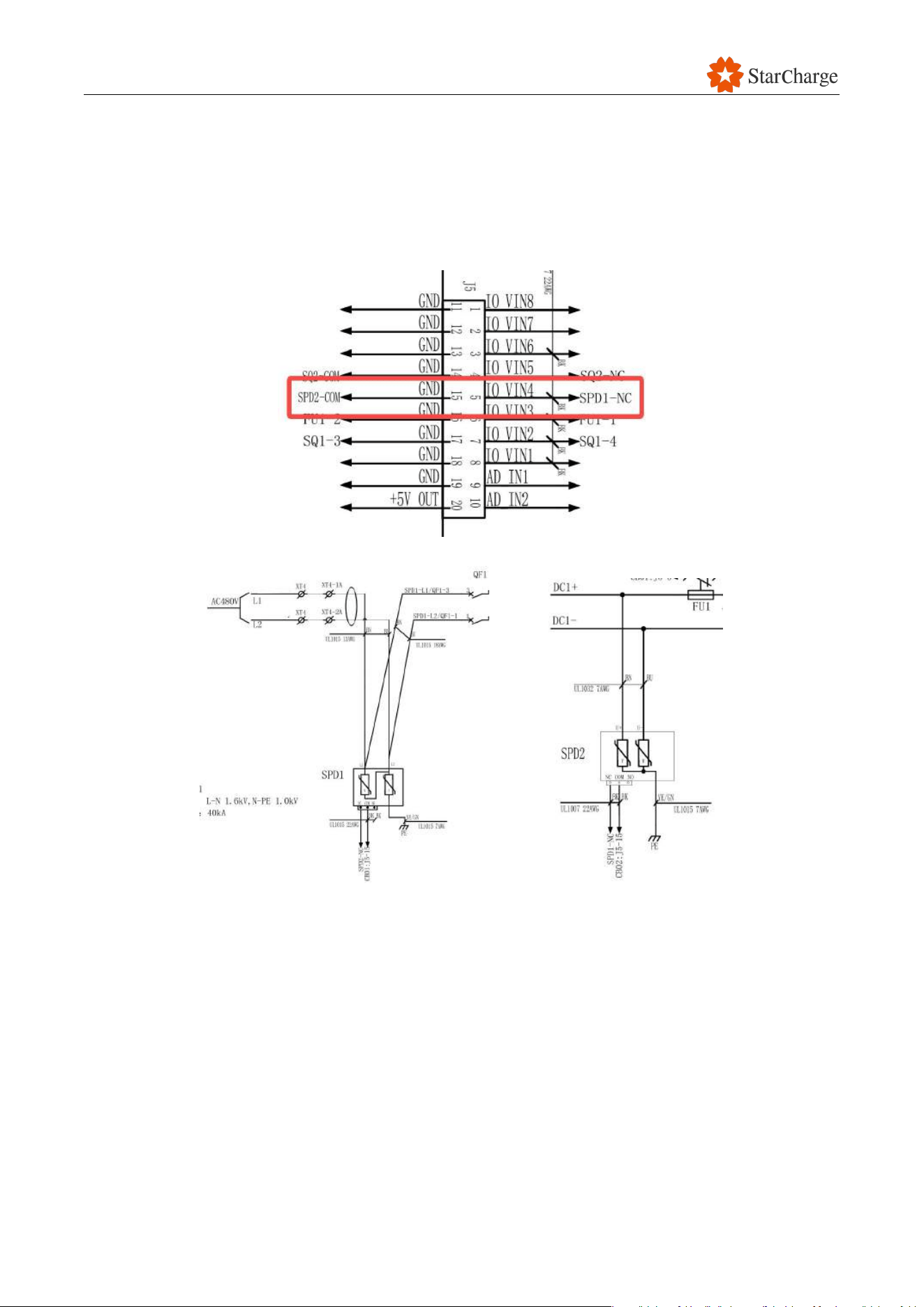
V 1.0.0 Star
126
8.19 Input surge protection alarm
Solution: Check the color of the indicator window on the surge protective device (SPD).
(1) If the indication window is red, replace a new SPD in time.
(2) If the indication window is green, please check whether the signal line from the SPD to the
control board is normal according to figure below.
V 1.0.0 Star
127
9 Technical specifications
9.1 Technical data
9.1.1 General parameters
Product name
Triton V2 UL Natural-cooling Dispenser
Product models
DC3000AN601926
9.1.2 Input parameters and grid parameters
Rated Input power
480V/2P+PE /2A 60Hz
Power factor
≥0.99 @ full load
Total harmonic current
≤5% @ more than half a load
Rectification efficiency
≥95% @ full load
Earthing system
TN-S, TN-C-S, TT
9.1.3 Output parameters
Output current
300A DC
Output voltage
150 to 1000V DC
9.1.4 Environmental parameters
Operating temperature
-30℃ to +50℃
Storage temperature
-40℃ to +70℃
Relative Humidity
5% to 95%
Altitude
≤2000m
Dust level
≤1 mg/m³
Corrosive substance
No pollutants, such as salt, acid, smoke, etc.
Vibration
≤1.5mm/s
2
Fire prevention
Do not stack flammable and explosive substances around
V 1.0.0 Star
128
9.1.5 Communication parameters
Network interface
Ethernet
9.1.6 User Interface & control
Mechanical button
Emergency stop
Start method
Local plug and charge
9.1.7 Mechanical parameters
Protection level
Type 3R
Cooling method
Natural-cooling
Dimensions (W×H×D)
500×500×300mm
Weight
Approx. 30kg (EVSE without charging cable)
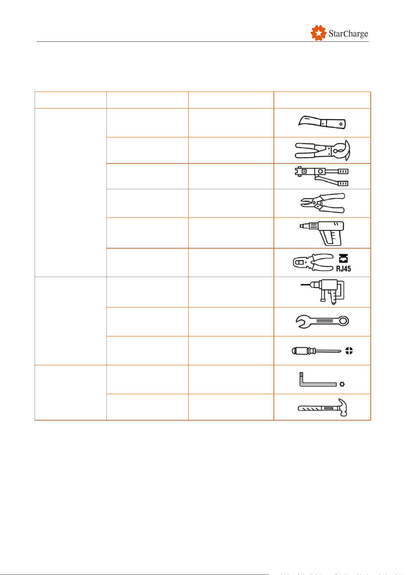
V 1.0.0 Star
129
9.2 Required tools
9.2.1 Required tools for installation
Category
Name
Usage
Picture
Cable preparation
tool
Electrician knife
Stripping of insulating
sheath
Cable cutter
Cable cutting
Hydraulic tongs
Terminal crimping
Wire stripping pliers
Stripping of insulating
sheath
Hot air gun
Thermal shrinkage of
insulating materials
Network cable pliers
Crimping of RJ45
connector
Installation tool
Percussion drill
Drilling hole
Open-end wrench (full
set)
Installing and removing
nuts
Cross screwdriver
(PH2)
Installing and removing
screws
Installation tool
Torx screwdriver
(full set)
Installing and removing
screws
Hammer
Knocking
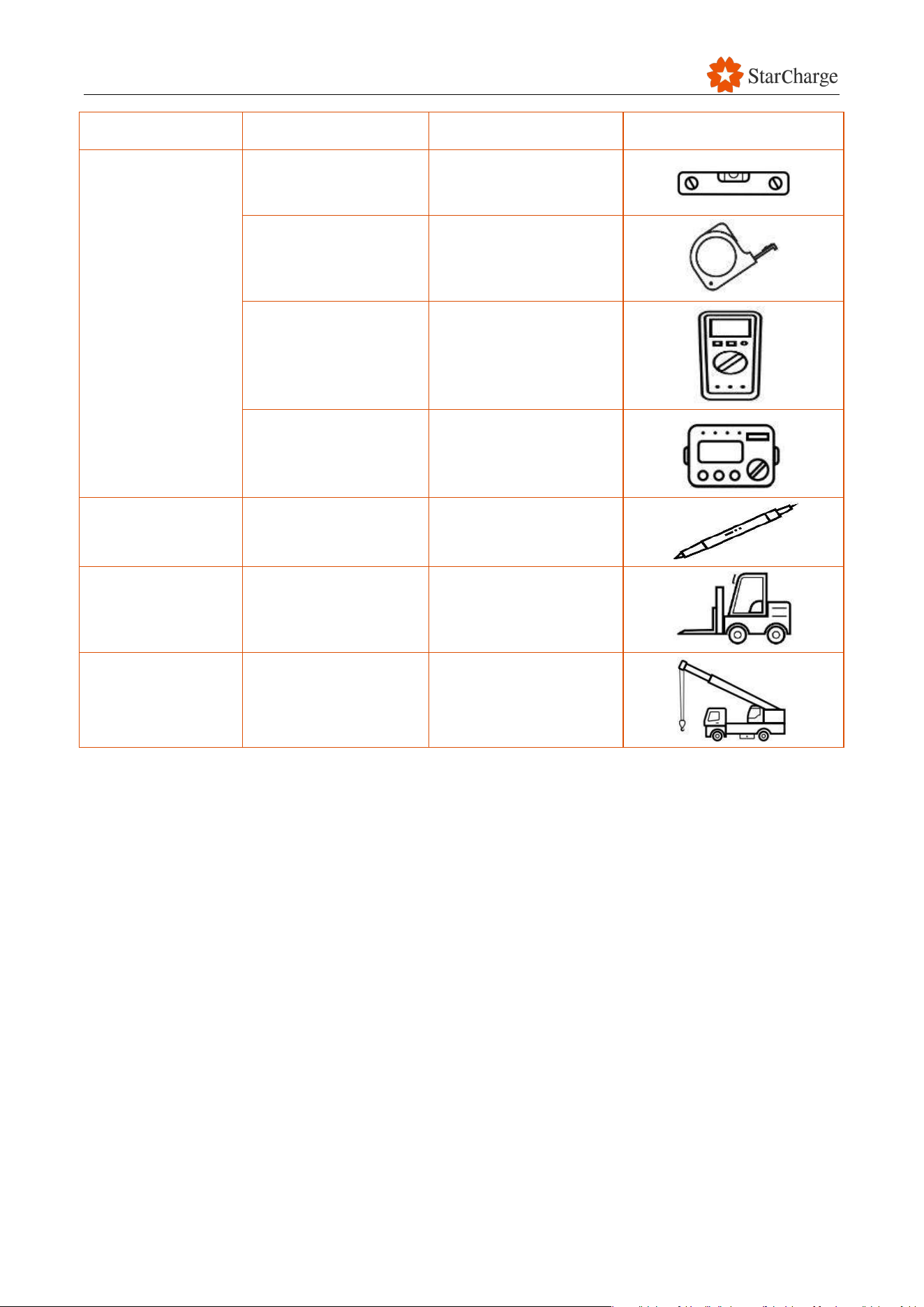
V 1.0.0 Star
130
Category
Name
Usage
Picture
Measurement tool
Spirit level
Horizontal
measurement
Tape measure
Distance measurement
Multimeter
Measurement of
voltage, current, etc.
Megger
Measurement of
resistance
Marking tool
Maker pen
Position making
Handling tool
Fork lift
Equipment handling
Hoisting tool
Crane
Equipment hoisting

V 1.0.0 Star
131
9.2.3 Bolts recommended Torque reference sheet
Bolt Specifications
Torque Range
(Unit: N·m)
Recommended Torque
(Unit: N·m)
M6
4.0-4.9
4.5
M8
8.8-10.8
10.0
M10
17.7-22.6
20.0
M12
31.4-39.2
36.0
M14
51.0-60.8
55.0
M16
78.3-98.1
83.0
M18
98.0-127.4
115.0
M20
156.9-196.2
180.0
M24
274.6-343.2
320.0

V 1.0.0 Star
132
9.4 Compliance and standard adhered to
9.4.1 Certification
Certificates:
9.4.2 Standards
The following documents are the design standards for this product:

V 1.0.0 Star
133
Customer service
Preparation:
If you have any questions or problems, please contact the company responsible
for performing the electrical installation.
Before contacting Customer Service:
Check the Troubleshooting chapter in the manual.