Smart Counter Provider
— 1 —
User's Manual
IR People Counter
FP111 ( WiFi Version)
Smart Counter Provider
Version V1.5
Smart Counter Provider
— 2 —
Table of Contents
1. Product Structure................................................................................ 3
1.1 Packing List .................................................................................3
1.2 Product size .................................................................................3
1.3 Product Power Supply .................................................................4
1.4 Appearance and Function ........................................................... 4
2. Networking Configuration....................................................................8
2.1 Configuration Notes .....................................................................8
2.2 Web Page Networking Configuration .......................................... 8
2.3 Mobile Phone Networking Configuration ................................... 11
3. Installation Instructions ......................................................................14
3.1 Installation Instructions ..............................................................14
3.2 Factors Affecting Accuracy ........................................................14
3.3 Installation Method .................................................................... 14
4. Installation Steps ...............................................................................15
Smart Counter Provider
— 3 —
1. Product Structure
1.1Packing List
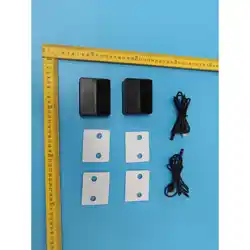
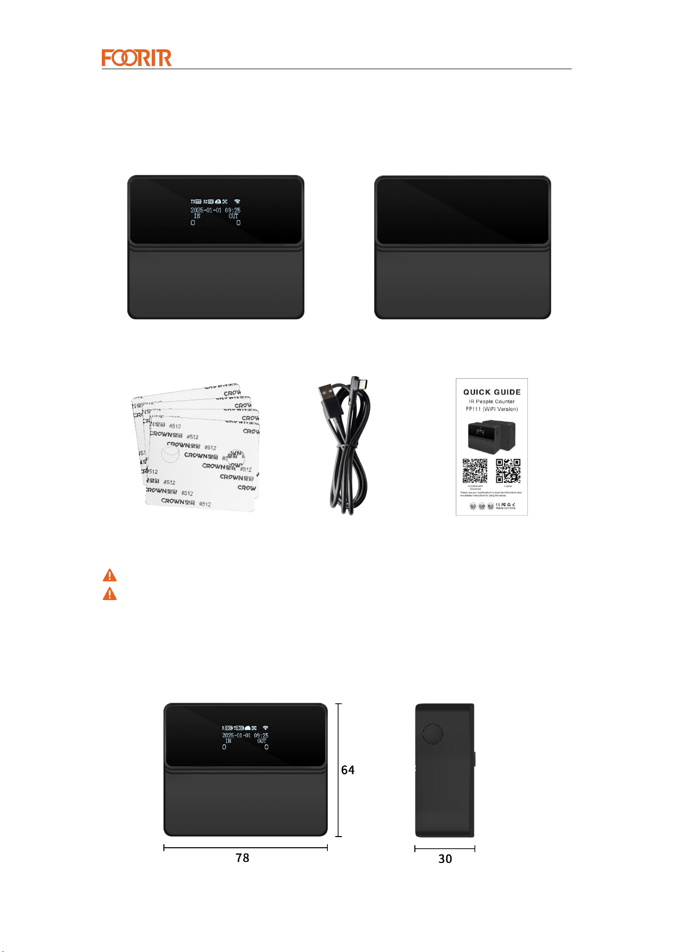
Receiver (R)*1 Transmitter (T)*1
3M Adhesive *4 Charging Cable *2 Quick Guide *1
The device contains 4 18650 batteries.
If any of the above items are damaged or lost, please contact your supplier in a
timely manner.
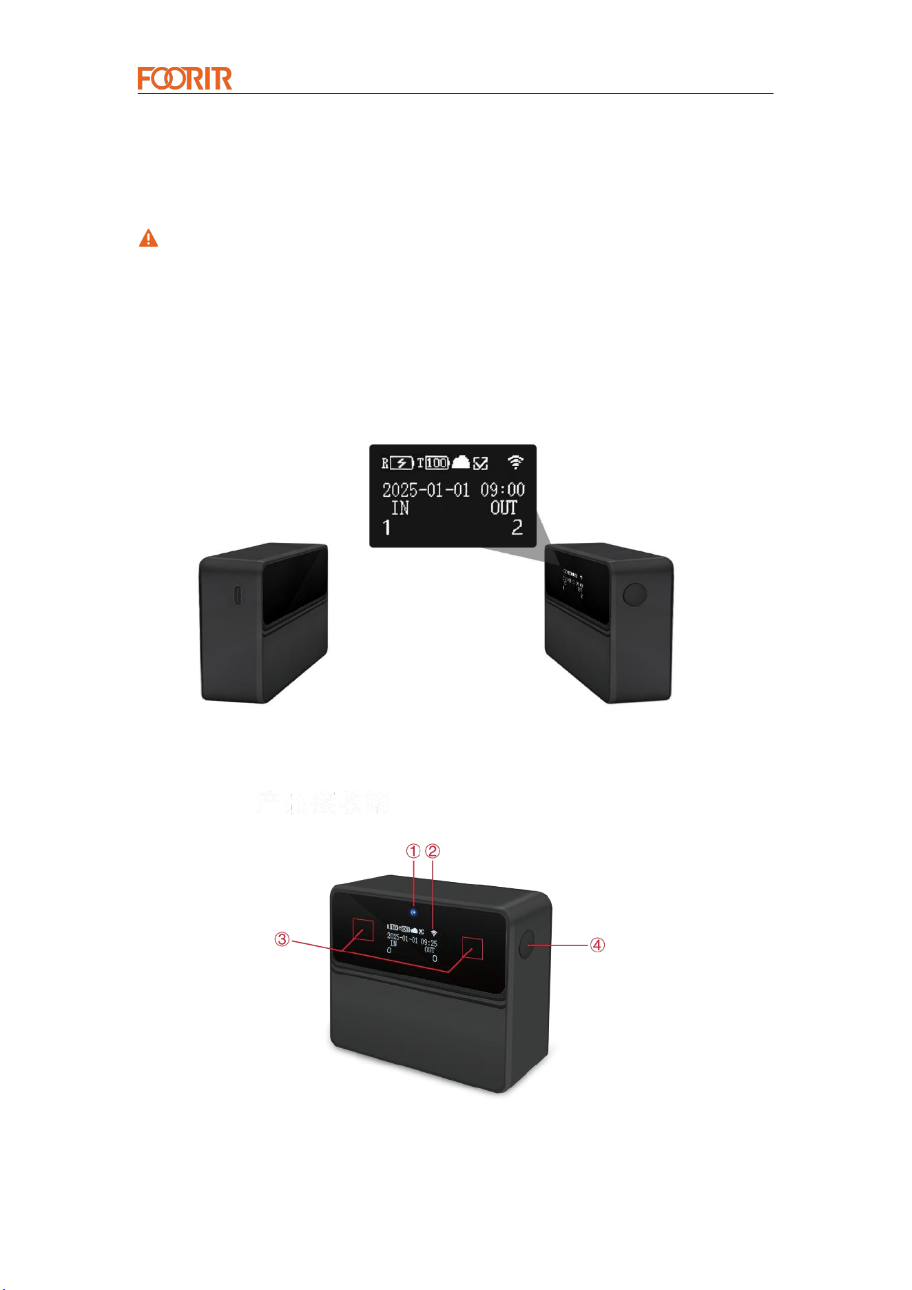
1.2 Product Size
Unit: mm
Smart Counter Provider
— 4 —
1.3 Product Power Supply
Flexible power supply options: Built-in 4 18650 batteries, supports Type-C
interface charging and external power supply (5V/2A adapter not included).
The device only supports 18650 batteries, and the indicator light will turn on if the
battery is reversely connected.
When the device is plugged into a USB port, it will display in three states:
Charging, Completed, and Constantly Powered.
1. Charging: The battery icon will display a lightning bolt.
2. Charging Completed: The battery icon will display the number 100.
3. Constantly Powered: The battery icon will display the number 100.
Charging interface
(the battery level of transmitter T can be viewed when the code is paired).
1.4 Appearance and Function
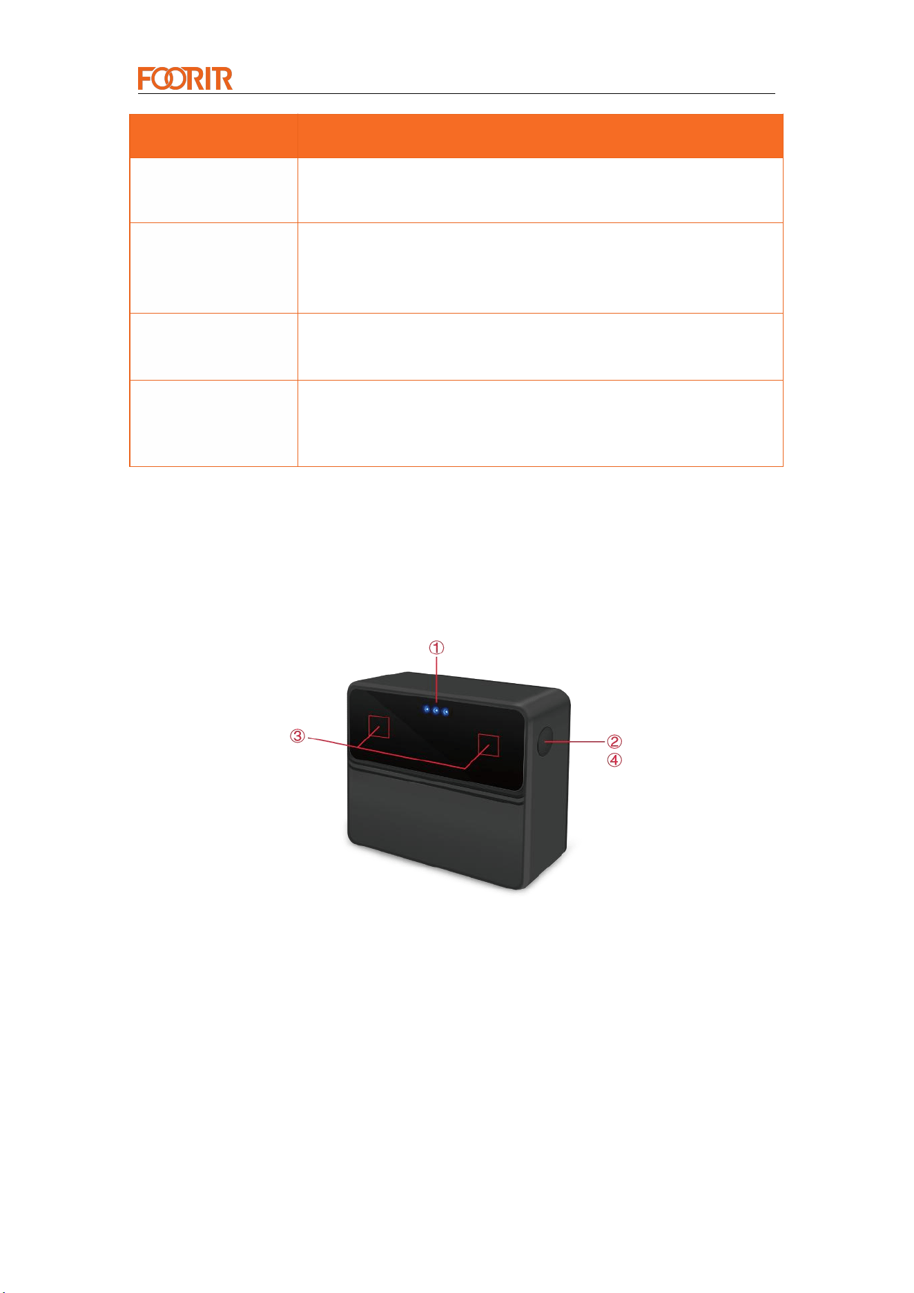
Receiver (R)
Smart Counter Provider
— 5 —
Name
Explain
①LED indicator
light
Blue indicator light: The indicator light flashes when the
receiver does not receive the transmitter signal or the battery is
low.
②OLED display
Press the button: Trigger the OLED screen to light up. If there
is no operation for more than 10 seconds, the display will
automatically turn off.
③Infrared receiver
module
Receive the infrared signal sent by the transmitter.
④Button
A short press wakes up the display.
A long press for 3 seconds turns on Bluetooth, and the
Bluetooth icon flashes.
A long press for 10 seconds restarts the device.
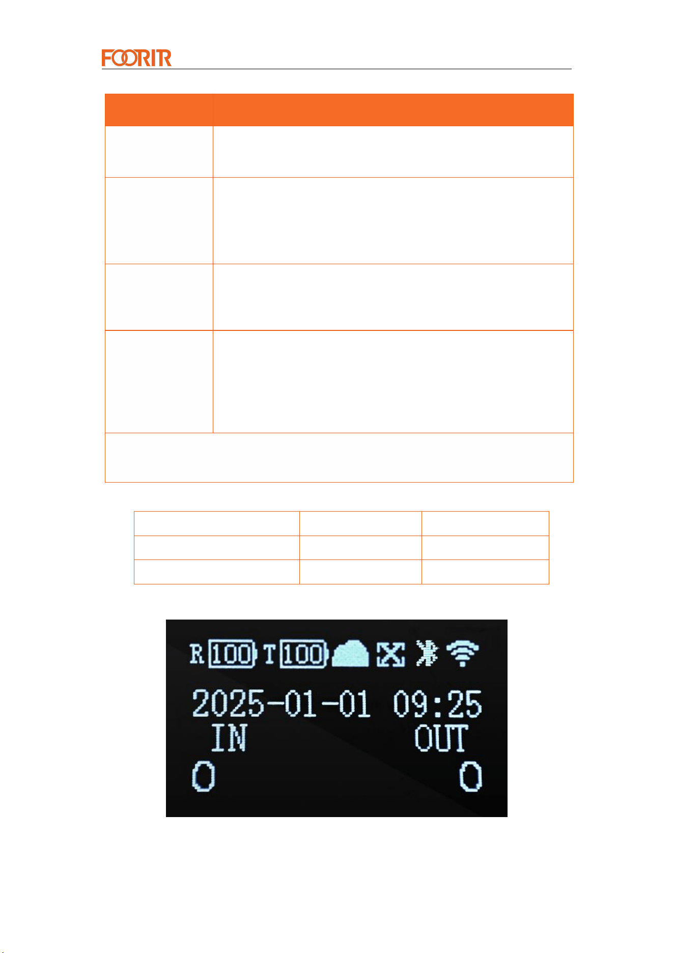
Transmitter (T)
Smart Counter Provider
— 6 —
Product Screen
1st gear <Close distance>
Indoors: 1-10m
Outdoors: 1-6m
2nd gear <Medium distance>
Indoors: 1-12m
Outdoors: 1-8m
3rd gear <Long distance>
Indoors: 1-15m
Outdoors: 1-9m
Name
Explain
① Status
indicator
Blue indicator light: When the battery is low, the indicator light
flashes.
② Button
Press once, and one indicator light will illuminate, indicating the
first gear position.
Press once, and two indicator lights will illuminate, indicating
the second gear position.
Press once, and three indicator lights will illuminate, indicating
the third gear position.
③ Infrared
transmitter
module
Transmits infrared wireless signals.
④ Transmitter
power switch
(factory default:
low power
consumption,
generally no
need to change)
Level 1: Low Power: Default setting.
Level 2: Medium Power: Press the button once to switch to
Level 2, and both indicators will flash.
Level 3: High Power: Press the button again to switch to Level
3, and all three indicators will flash.
Note: The higher the power, the longer the transmission distance and the shorter
the device standby time.
Smart Counter Provider
— 7 —
Pattern
Explain
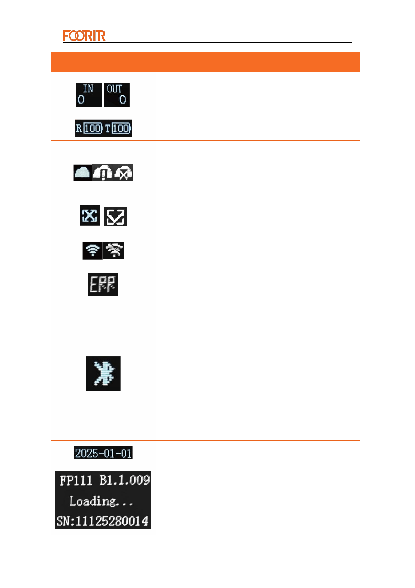
IN represents the number of people entering, and OUT
represents the number of people leaving.
R represents the power level of the receiving end, T represents
the power level of the transmitting end, and lightning represents
charging.
The platform connection status icon displayed on the device
screen has three states: successful data upload, device not
linked to the platform, and data upload failure.
A cloud with an upload arrow indicates data is uploading.
An X indicates data upload failure (check your WiFi
network/server configuration).
√ indicates successful pairing with the transmitter
X indicates the device is out of focus
The WiFi icons represent successful and failed connections.
The WiFi strength of the connection is divided into four bars,
with four bars indicating the strongest WiFi signal and one bar
indicating the weakest.
ERR: If the "Module Not Responding" icon appears in the
"Signal" position on the screen, communication between the
MCU and the module is not working properly. If "No Signal"
appears in the "Signal" position, the WiFi signal between the
module and the router is very weak or not connected.
If the Bluetooth icon flashes, it means Bluetooth is on. If the
Bluetooth icon does not flash, it means the device is connected.
Turn Bluetooth on and off
(1) Turn Bluetooth on
When the device's Bluetooth is not on and the device screen does not display
Bluetooth, long press the right button for 2s to 8s and the Bluetooth icon will
appear on the device screen. Release the button and the device will turn on
Bluetooth.
(2) Bluetooth connection and disconnection judgment
Bluetooth disconnected state: When Bluetooth is on and not connected, the
Bluetooth icon on the screen will be displayed in a 1s cycle.
Bluetooth connected state: When Bluetooth is on and connected, the Bluetooth
icon on the screen will be constantly lit.
(3) Turn Bluetooth off
When the device's Bluetooth is on (the screen displays the Bluetooth icon), long
press the right button for 2s to 8s and the icon on the screen will go out. Release
the button and the device will turn off Bluetooth.
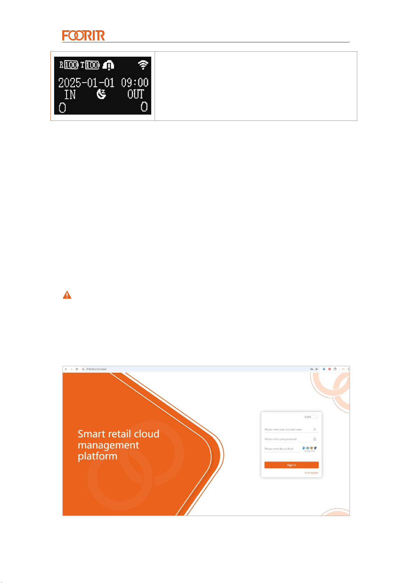
If the server time is not synchronized, the default value is
2025-01-01. If the server time is successfully synchronized, the
server time is displayed.
Power-on interface: The device automatically powers on after
powering on. The blue indicator light will illuminate for 1 second
before turning off, and the screen will display the power-on
interface. FP111 is the device model, B1.1.009 is the device
version number, and SN:XXX is the device's unique
identification code.
Smart Counter Provider
— 8 —
Sleep interface: The device will not be counted during
non-business hours. The non-business hours display icon is
between "IN" and "OUT" in the third row.
2. Networking Configuration
2.1 Configuration Notes
Network configuration: It consists of web page network configuration and mobile
phone network configuration.
Perform networking configuration before device installation
Before configuration, you need to go to the web page to bind the device. For
specific steps, refer to the web page network configuration
configuring mobile phone network , you need to fill in the accurate server address
and port
If the device is pushed to a third-party server, please skip the web configuration
step
If there are any rules, restrictions, or DNS-related settings on the network , the
device may not be able to successfully connect to the server.
2.2 Web Page Networking Configuration
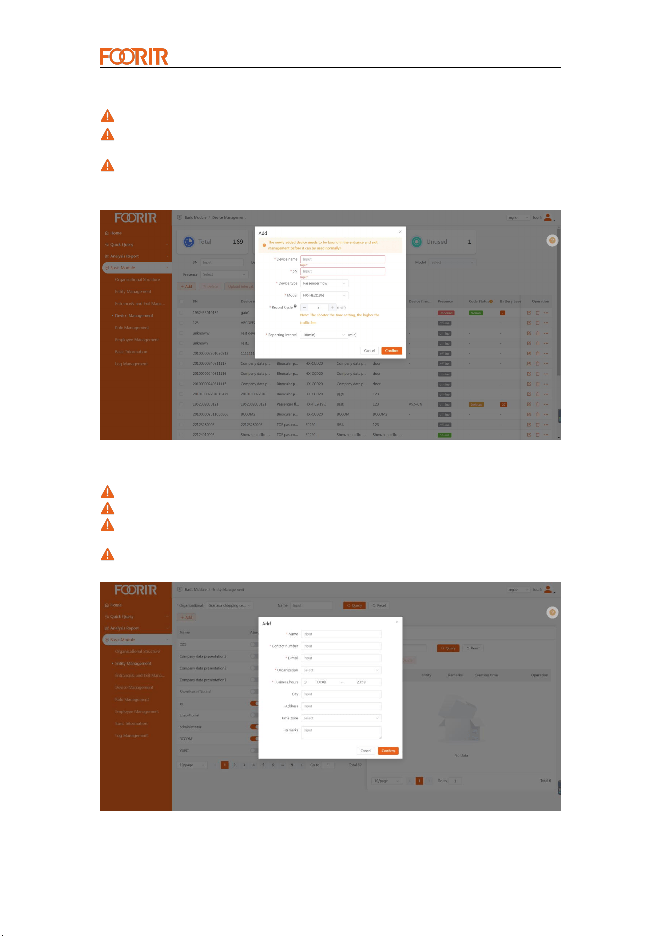
Step 1: Visit the cloud platform vf.foorir.com to register an account.
Smart Counter Provider
— 9 —
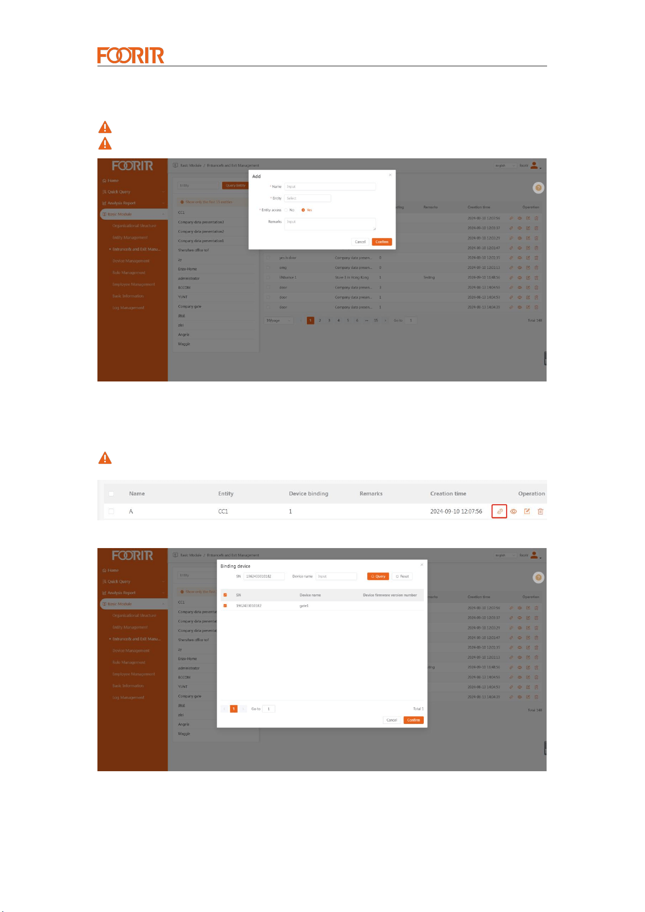
Step 2: Add a device, select "Basic Module- > Device Management- > Add Device"
The device name is recommended to fill in the device installation location
The serial number is the unique identification code of the device and must be filled
in strictly according to the serial number displayed on the device
Serial Number Check: Refer to the <SN> on the power-on screen and the label on
the back of the receiver (after opening the back cover).
Step 3: Create an entity , select "Basic Module- > Entity Management- > Add Entity"
Email: used to push abnormal status of the device
Organizational structure: Select the default structure
Business Hours: Used to synchronize device working hours, counted during
business hours and not counted outside business hours.
Time zone: used to synchronize device time. It is selected according to the local
time zone.
Smart Counter Provider
— 10 —
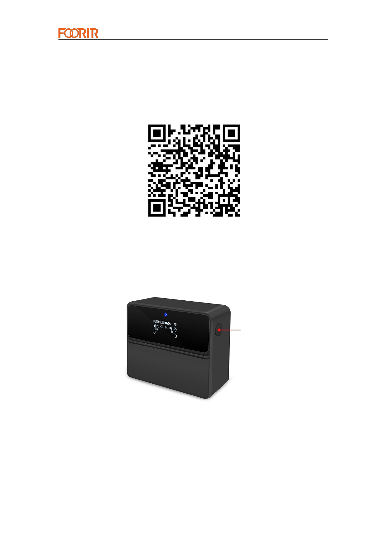
Step 4.1: Create an entrance and exit, select "Basic Module- > Entrance and Exit
Management- > Add Entrance and Exit"
Belonging entity: Select the created entity
Physical entrance and exit: Select "Yes"
Step 4.2: Bind the device , select the entrance and exit to be bound, click the binding
icon at the back, enter the binding page, check the device to be bound, and click "
Confirm " ; the web networking configuration is completed.
After completing this step, you can configure the mobile phone network.
Smart Counter Provider
— 11 —
2.3 Mobile Phone Networking Configuration
Configure network connectivity before installing the device.
Please use your browser to scan the QR code to download the "FOORIR" app.
IOS users can search for "FOORIR" in the App Store to download it.
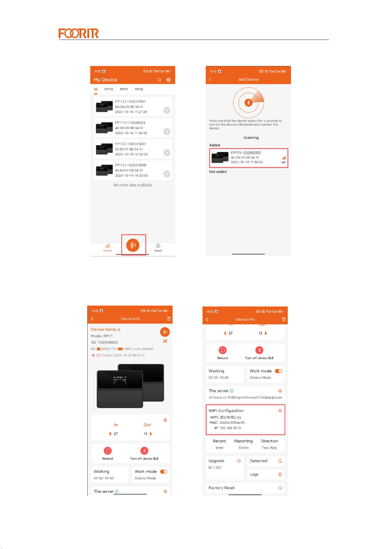
Step 1: Activate Bluetooth.
Press and hold the button for 3 seconds to power on the device, then press and hold
the button again for 3 seconds to activate the device's Bluetooth.
Step 2: Search and add a device.
Scan for Bluetooth devices and find your device in the list.
The device name format is: model number + the last 8 digits of the serial number
(Refer to the <SN on the power-on screen> and the label on the back of the receiver
(after opening the back cover) for details.).
Select the device to add it.
Button
Smart Counter Provider
— 12 —
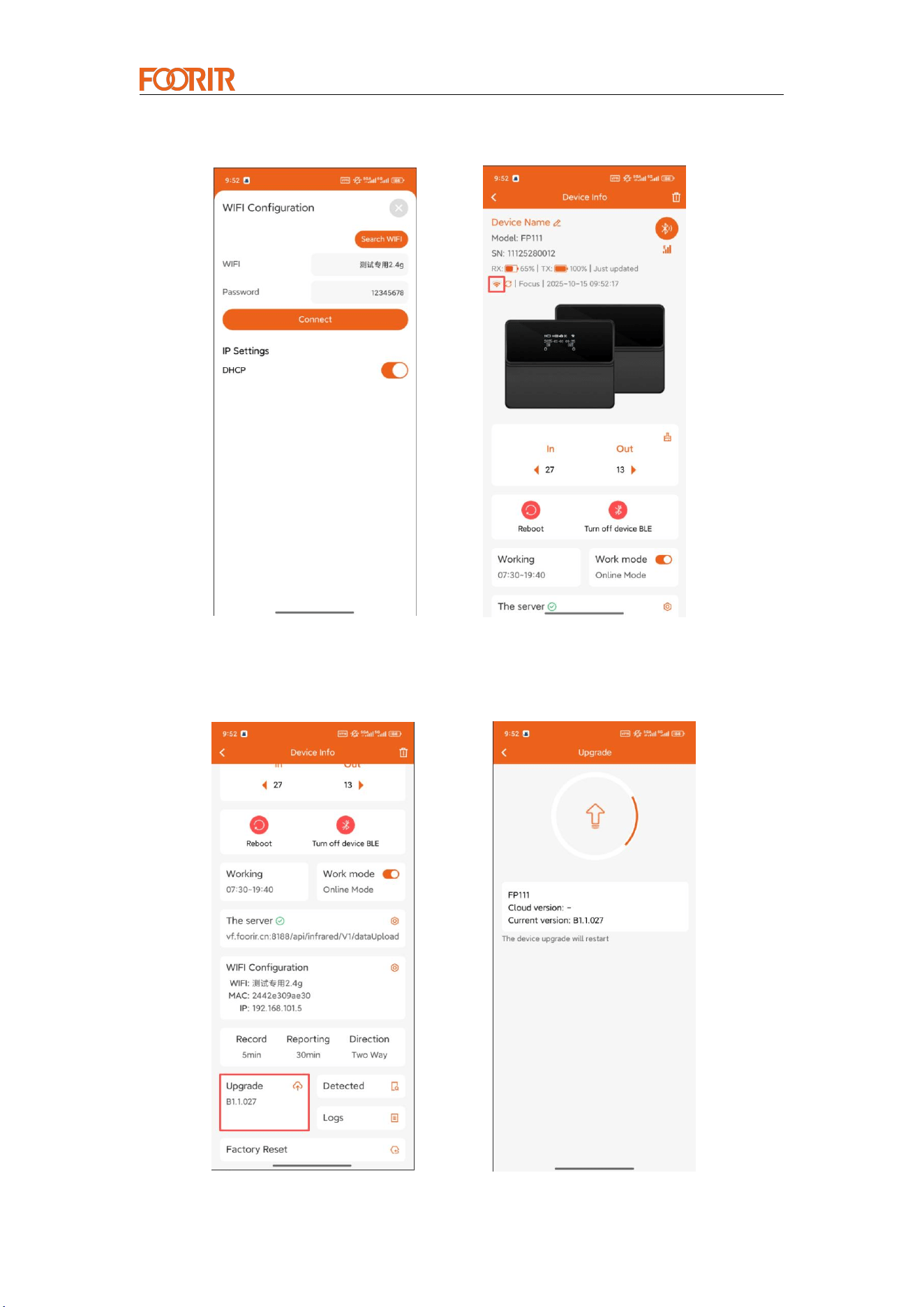
Step 3: WiFi Configuration.
Go to the device configuration page and scroll down to the "WiFi Configuration" area.
Smart Counter Provider
— 13 —
Select the WiFi network you want to connect to, enter the password, and confirm it.
Check the WiFi connection status.
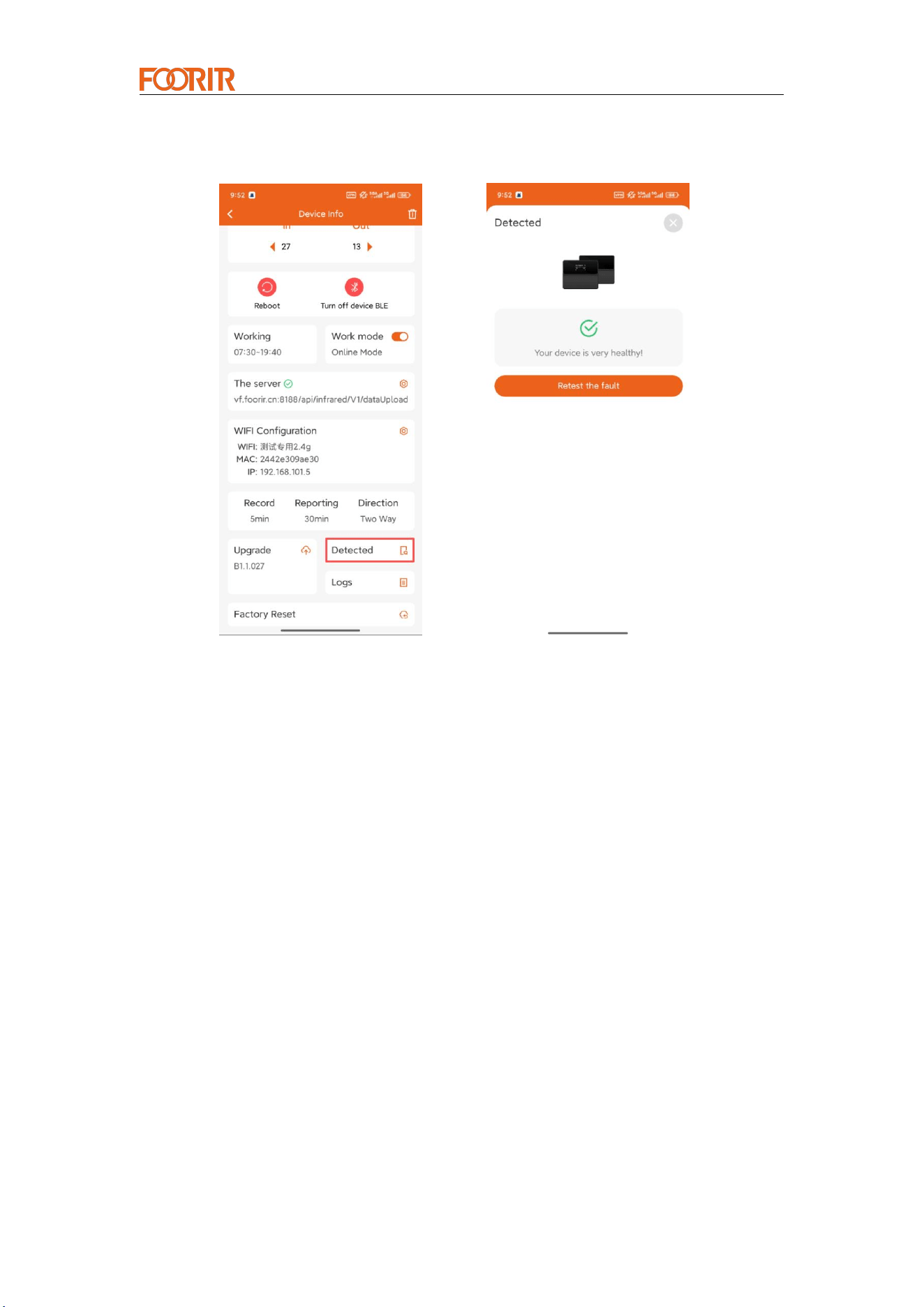
Maintenance 1: Equipment upgrade.
The system will detect whether there is a new version. If there is a new version, you
can directly download the firmware from the cloud to the device for upgrading.
Smart Counter Provider
— 14 —
Maintenance 2: Fault Detection.
After the setup is complete, if the device does not work properly or there is a problem
with the data, you can click Fault Detection here to help you identify the problem.
3. Installation Instructions
3.1 Installation Instructions
At the installation location, first configure the network and then install the
device
The receiving end is installed on the right hand side of the channel
entrance direction
There should be no obstructions between devices. If there is glass, the
higher the light transmittance, the less impact it has on accuracy.
The recommended installation height is 1.2-1.4m, and the receiving
end and the transmitting end should be installed parallel and aligned.
3.2 Factors Affecting Accuracy
The devices cannot be blocked by people or objects for a long time, which
will cause the devices to lose focus.
If two people pass side by side, there will be omissions.
If you hold a large object or push a shopping cart through, there is a
chance that it will be recorded incorrectly.
3.3 Installation Method
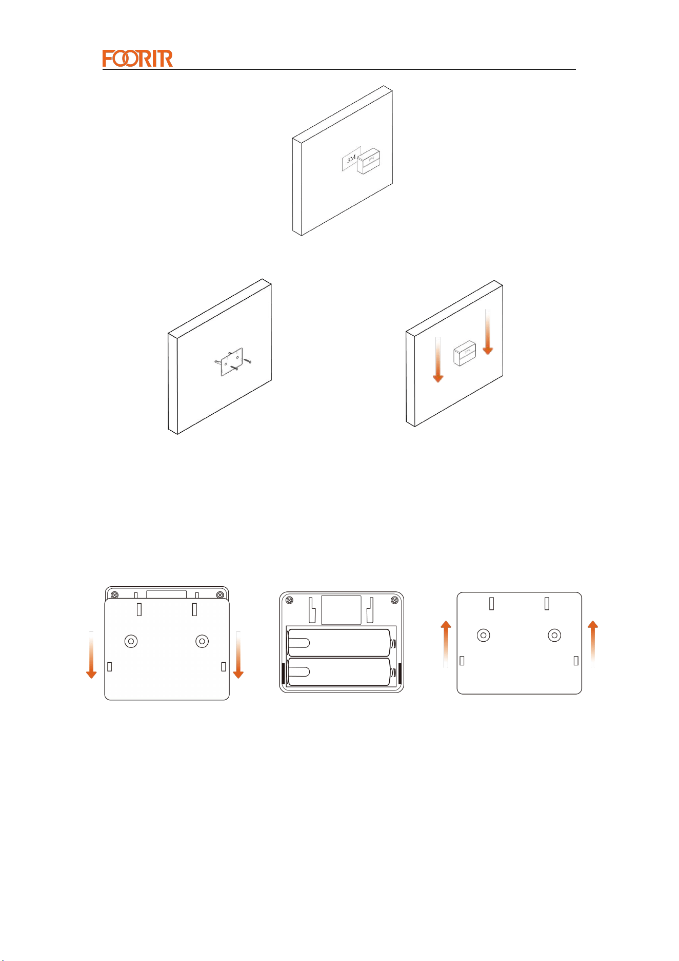
Two installation methods: 3M adhesive or screw fixation
Smart Counter Provider
— 15 —
3M Adhesive
Screw Fixation
4. Installation Steps
Step 1: Open the box, take out the two devices, and remove the battery
insulating sheet from each.
① Slide the back cover down. ② Remove the insulating sheet. ③ Slide it up to close.
Step 2:
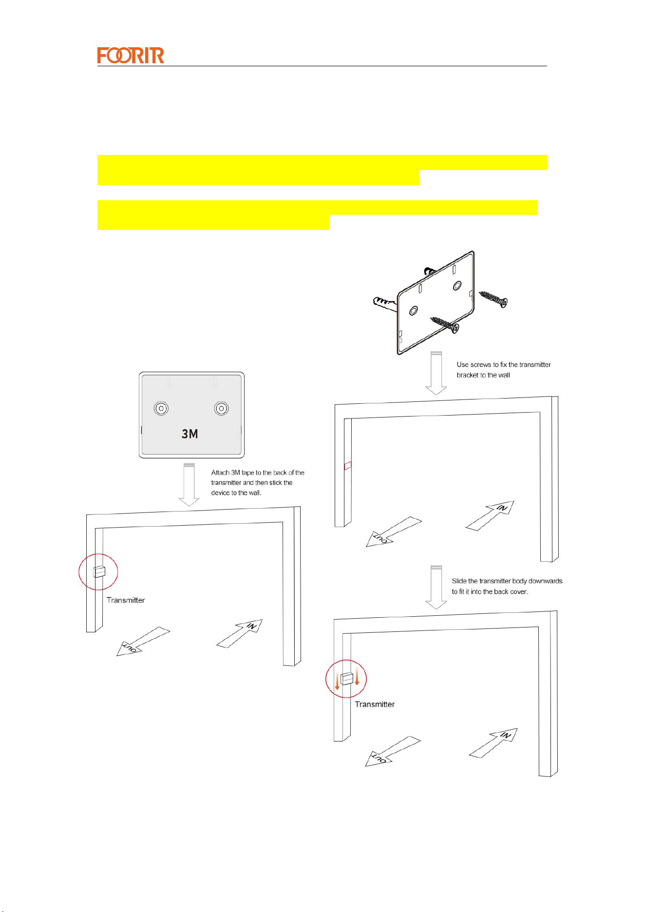
Installation Method 1 (Attaching with 3M Tape): First, install the transmitter
to facilitate receiver pairing. Remove the 3M tape from the packaging and
apply it to the back of the device. Then, secure the transmitter to the left side of
the door.
Smart Counter Provider
— 16 —
Installation Method 2 (Securing with Screws): First, install the transmitter to
facilitate receiver pairing. Remove the transmitter's back cover, secure it to the
wall with screws, and slide the transmitter downward to mate with the back
cover.
* It is recommended to install according to the direction shown in the diagram,
ensuring both ends are horizontally aligned and parallel.
* Left and right sides are interchangeable, and the direction of entry and exit
can be flexibly set on the cloud platform.
Installation Method 1
(Attaching with 3M Tape)
Installation Method 2
(Securing with Screws)
Smart Counter Provider
— 17 —
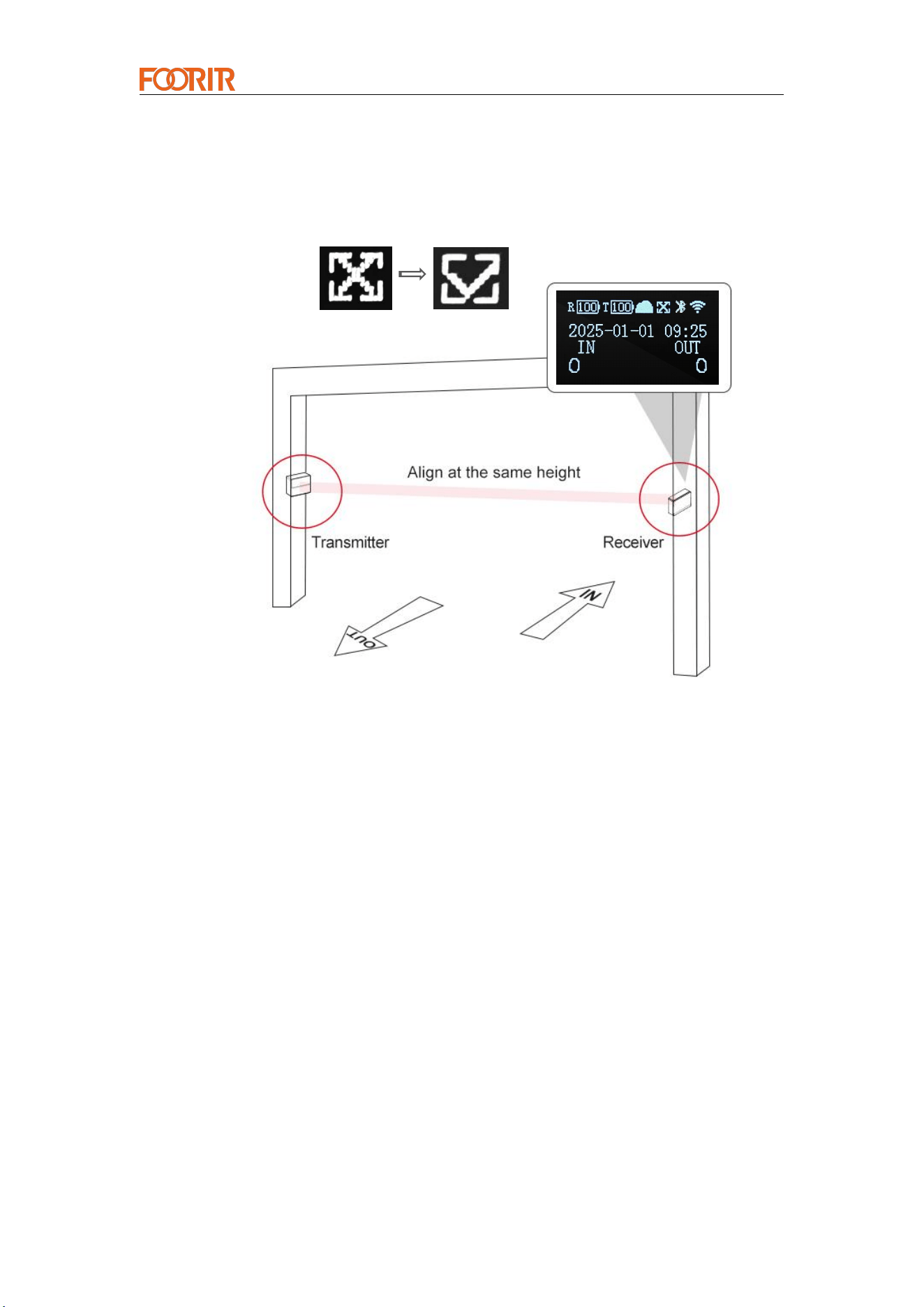
Step 3: Pairing is performed at the pre-set installation location. Align the
receiver and transmitter parallel to each other, making small adjustments until
the "×" changes to a "√" sign, indicating a successful pairing. Mark the
pre-installation location for the receiver and then secure it to the wall.
Smart Counter Provider
— 18 —
Statement
Copyright © 2011- 2024 Chengdu Huaxin Zhiyun Technology Co., Ltd.
Copyright All Rights Reserved
Without the explicit written permission of Chengdu Huaxin Zhiyun Technology
Co., Ltd., no organization or individual may reproduce, copy, transcribe or
translate part or all of the contents of this manual without authorization, and
may not disseminate it in any way (electronic, photocopying, recording, etc.)
for profit-making purposes.
It is a registered trademark of Chengdu Huaxin Zhiyun
Technology Co., Ltd. All trademarks mentioned in this manual are owned by
their respective owners.
The product specifications and information mentioned in this manual are for
reference only. If there is any content update, no further notice will be given.
Unless otherwise agreed, this manual is only used as a guide, and the
statements made do not constitute any form of warranty.
For assistance, please contact:
Manufacturer: Chengdu Huaxin Zhiyun Technology
Co., Ltd.
Phone/WhatsApp:+86 18981978865
Email:info@foorir.com
Official website: www.foorir.com
www.foorir.com
Phone/WhatsApp:+86 18981978865
E-mail:info@foorir.com
Address: Room 4021, Unit 1, Building 1, 88 Tianchen Road, High-Tech Zone, Chengdu, Sichuan, China
FCC Statement
Note: This equipment has been tested and found to comply with the limits for a Class B
digital device, pursuant to part 15 of the FCC Rules. These limits are designed to
provide reasonable protection against harmful interference in a residential installation.
This equipment generates, uses and can radiate radio frequency energy and, if not
installed and used in accordance with the instructions, may cause harmful interference
to radio communications. However, there is no guarantee that interference will not occur
in a particular installation. If this equipment does cause harmful interference to radio or
television reception, which can be determined by turning the equipment off and on, the
user is encouraged to try to correct the interference by one or more of the following
measures:
—Reorient or relocate the receiving antenna.
—Increase the separation between the equipment and receiver.
—Connect the equipment into an outlet on a circuit different from that to which the
receiver is connected.
—Consult the dealer or an experienced radio/TV technician for help.
This device complies with part 15 of the FCC Rules. Operation is subject to the following
two conditions:(1) This device may not cause harmful interference, and (2) this device
must accept any interference received, including interference that may cause undesired
operation.
Any changes or modifications not expressly approved by the party responsible for
compliance could void the user's authority to operate the equipment.
The device has evaluated to meet general RF exposure requirement. The device can be
used be in portable exposure without restriction.