BULLETIN NO.
54-49-8401
SERVICE PARTS LIST
CATALOG NO.
REVISED BULLETIN
SPECIFY CATALOG NO. AND SERIAL NO. WHEN ORDERING PARTS
PACKOUT
™
Tool Boxes
DATE
Oct. 2025
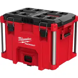
48-22-8425 PACKOUT
™
Large Tool Box Page 1
48-22-8424 PACKOUT
™
Medium Tool Box Page 2
48-22-8450 PACKOUT
™
Tool Box Page 3
48-22-8422 PACKOUT
™
Compact Tool Box Page 4
48-22-8429 PACKOUT
™
XL Tool Box Page 5
48-22-8423 PACKOUT
™
XL Tool Box Page 6
EXAMPLE:
Component Parts (Small #) Are Included
When Ordering The Assembly (Large #).
0
00
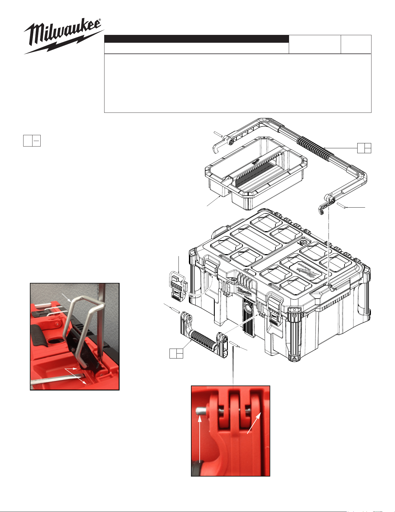
As an aid to removing a damaged Latch
Assembly, use two large at blade
screwdrivers. Push blades between parts
as shown. Twist both screwdrivers at same
time to force the blades into opening
and work the latch assembly over the
two locking tabs.
To install a new latch assembly,
position entire latch assembly over
locking tabs with the two top lugs
partially inserted in 'catch cavity' of
main housing. Engage latch bar
onto lid and gently press latch lever
to slide assembly over two locking
tabs and into place.
This removal and installation process will be the same
where other service latches are oered in this system.
MILWAUKEE TOOL
l
www.milwaukeetool.com
13135 W. LISBON RD., BROOKFIELD, WI 53005
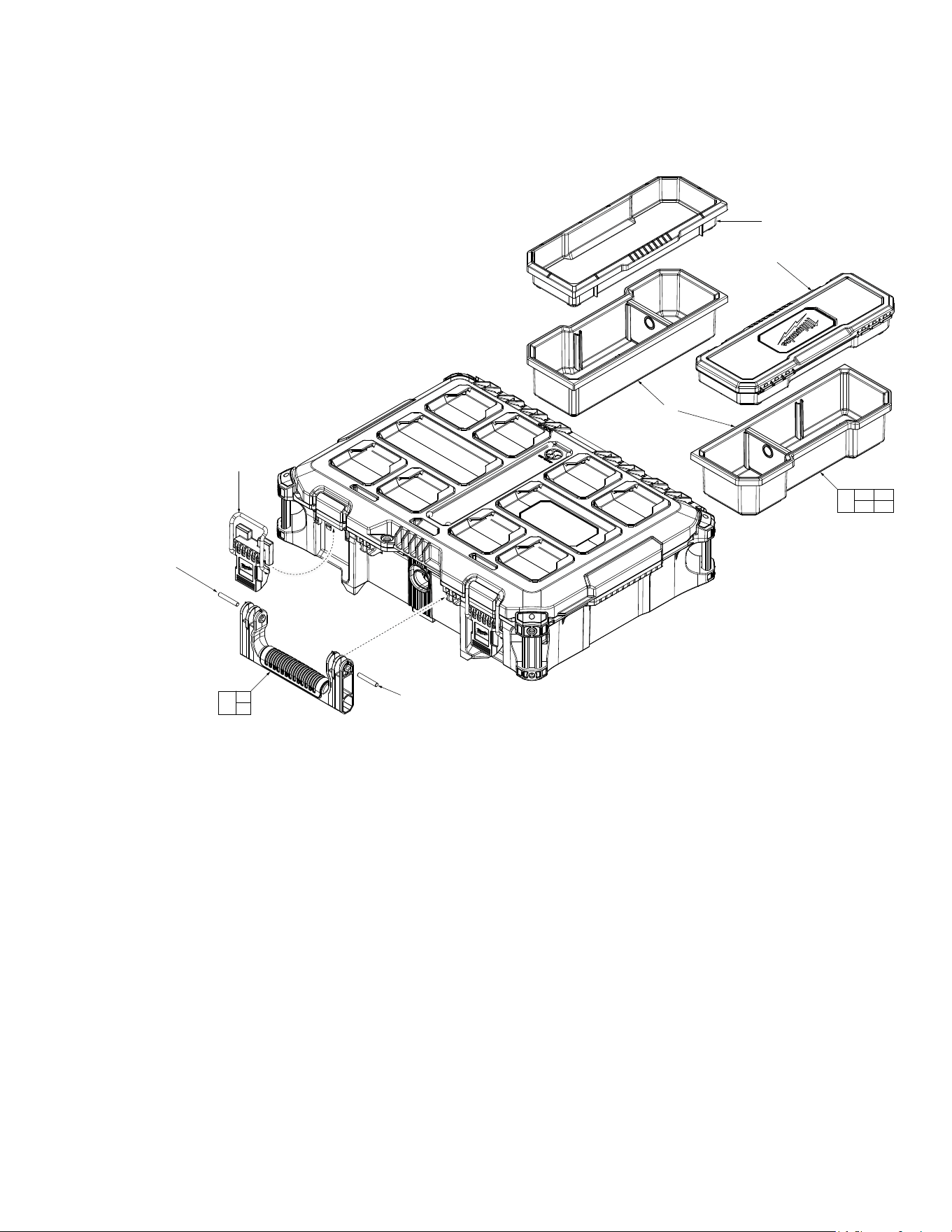
Drwg. 2
2
1
2
(2x)
6
4
3
4
(2x)
5
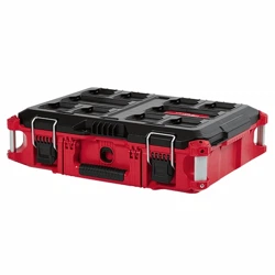
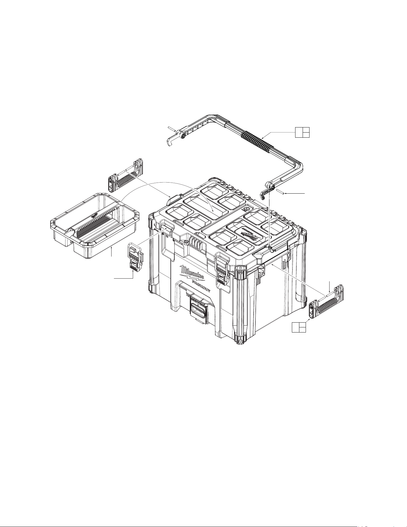
FIG. PART NO. DESCRIPTION OF PART NO. REQ.
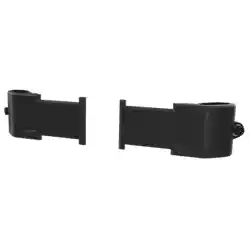
1 43-62-8425 Top Handle Service Kit (1)
2 --------------- Pin (2)
3 43-62-8424 Side Handle Service Kit (1)
4 --------------- Pin (2)
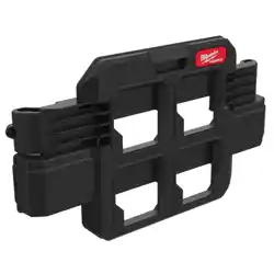
5 44-20-8400 Latch Service Assembly (Set of 2) (1)
6 31-01-8400 Storage Tray (1)
7 43-44-8400 Lid Gasket (Not Shown) (1)
48-22-8425 PACKOUT™ (Large) Tool Box
Pins to be
installed from
the inside of
the handle.
Locking Tabs
Latch Assembly
Place flat blade
screwdriver in
here and work
pin to the inside.
Grab exposed pin with needle
nose pliers and work out.
2
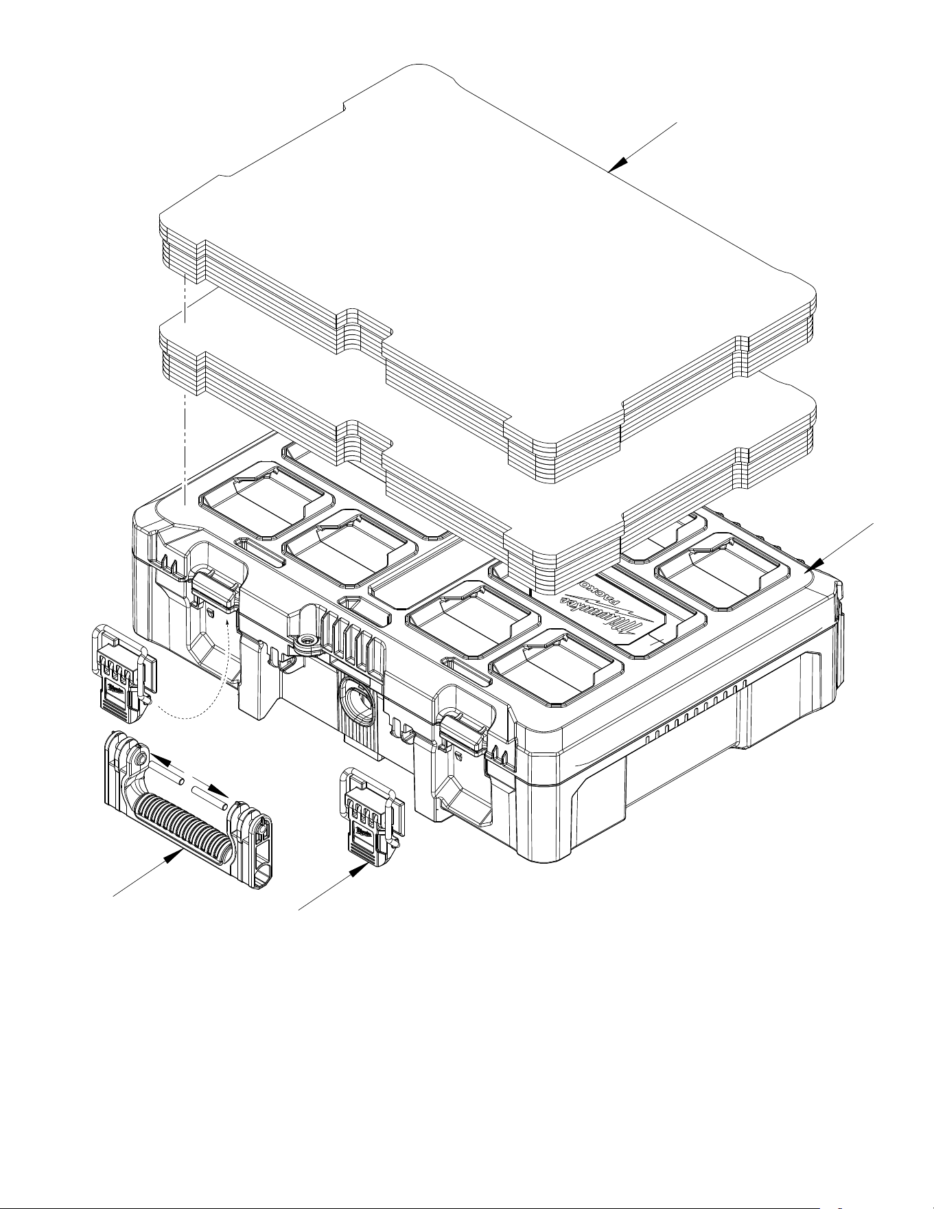
FIG. PART NO. DESCRIPTION OF PART NO. REQ.
3 43-62-8424 Side Handle Service Kit (1)
4 --------------- Pin (2)
5 44-20-8400 Latch Service Assembly (Set of 2) (1)
7 43-44-8400 Lid Gasket (Not Shown) (1)
8 31-01-8424 Storage Bin Kit (Set of 4) (1)
8a --------------- Deep Bin with Two Dividers (2)
8b --------------- Shallow Bin (1)
8c --------------- Shallow Bin with Cover (1)
48-22-8424 PACKOUT™ (Medium) Tool Box
4
3
4
(2x)
5
8a
(2x)
8b
8c
8a 8b
8c
8
Pins to be installed from the
inside of the handle.
3
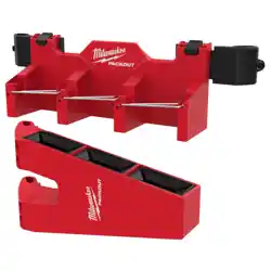
FIG. PART NO. DESCRIPTION OF PART NO. REQ.
1 43-62-8450 Kit Box Mono Block Handle with 2 Pins (1)
2 44-20-8430 Latch Service Assembly (Set of 2) (2)
3 43-44-8400 Lid Gasket (Not Shown) (1)
4 48-22-8451 Foam Insert for PACKOUT™ Kit Box (Set of 2) (1)
48-22-8450 PACKOUT™ Tool Box Kit with Foam Dividers
3
4
1
2
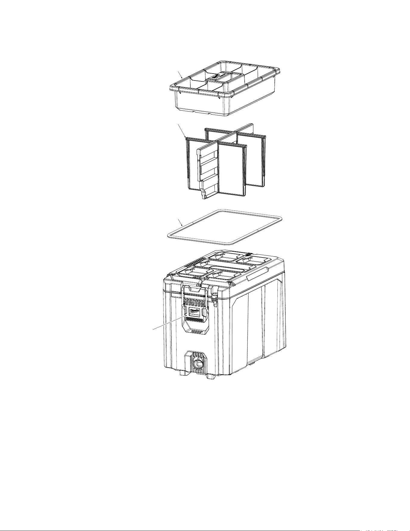
4
FIG. PART NO. DESCRIPTION OF PART NO. REQ.
1 44-20-8422 Latch Assembly (1)
2 43-44-8422 Gasket
(1)
3 31-01-8423 Dividers (1)
4 31-01-8422 Tray (1)
48-22-8422 PACKOUT™ Compact Toolbox
Note: Tray, Dividers and Gasket
illustrated outside of PACKOUT, is to
be assembled on the inside.
4
3
2
1
5
48-22-8429 PACKOUT™ XL Tool Box
FIG. PART NO. DESCRIPTION OF PART NO. REQ.
1 44-20-8400 Latch Service Assembly (Set of 2) (1)
2 --------------- Pin (4)
3 31-01-8400 Service Tray (1)
4 43-62-8426 Service Side Handle (Set of 1) (2)
5 43-44-8400 Lid Service Gasket (Not Shown) (1)
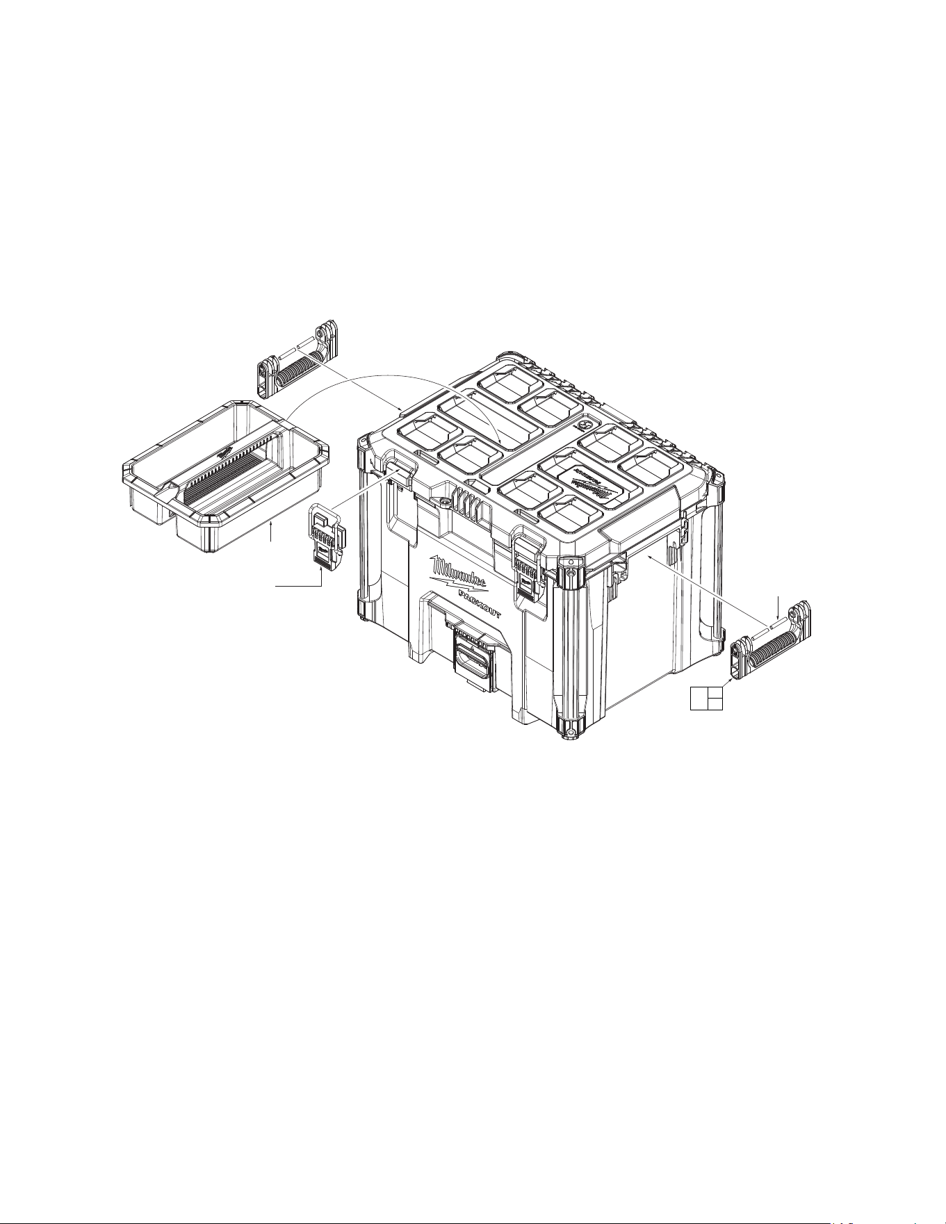
3
1
2
4
2
(4x)
6
48-22-8423 PACKOUT™ XL Tool Box
FIG. PART NO. DESCRIPTION OF PART NO. REQ.
1 43-62-8425 Top Handle Service Kit (1)
2 --------------- Pin (6)
3 43-62-8424 Service Side Handle Kit (Set of 1) (2)
4 44-20-8400 Latch Service Assembly (Set of 2) (1)
5 31-01-8400 Service Tray (1)
6 43-44-8400 Lid Service Gasket (Not Shown) (1)
5
4
2
1
2
3
2
(2x)
2
(4x)