
Operator’s Manual
www.mechmaxx.com
WARRANTY


TABLE OF CONTENTS
TABLE OF CONTENTS
SPECIFICATIONS
SAFETY SIGNS
SAFETY
1
2
CHANGING THE BLADE
REPLACING BELTS
25
25
WORK AREA
PERSONAL SAFETY
TOOL USE AND CARE
4
4
4
START UP PROCEDURE – EQUIPMENT OPERATION
5
GENERAL MAINTENANCE INFORMATION
5
PARTS INSPECTION
PARTS CHECKING LIST
TRACKS ASSEMBLY
3
4
7
7
8
9
LOG DOG & SUPPORTS
MAKE THE CROSS ARM ON THE TRACKS AT SAME LEVEL
CARRIAGE ASSEMBLY
10
11
12
ELECTRICAL DIAGRAM
19
BELT TENSION
20
BLADE TRACKING
20
ADJUSTING THE RIGHT HAND SIDE
21
ADJUSTING THE LEFT HAND SIDE
22
MOVING THE BLADE FORWARD
22
MOVING THE BLADE REARWARD
22
BLADE GUIDE ADJUSTMENT
23
BLADE TENSION
23
ASSEMBLY
25
SAWMILL MAINTENANCE
20
SAWMILL SET-UP PROCEDURES
27
TROUBLESHOOTING
29
DIAGRAM(A)-BAND WHEEL HOUSING
30
PARTS LIST(A)-BAND WHEEL HOUSING
33
DIAGRAM(B)-CARRIAGE
34
PARTS LIST(B)-CARRIAGE
36
DIAGRAM(C)
37
PARTS LIST(C)
38
DIAGRAM(C)-EXTEND RUNWAY (OPTIONAL)
39
PARTS LIST(C)-EXTEND RUNWAY (OPTIONAL)
1
www.mechmaxx.com
TABLE OF CONTENTS

SPECIFICATIONS
2
www.mechmaxx.com
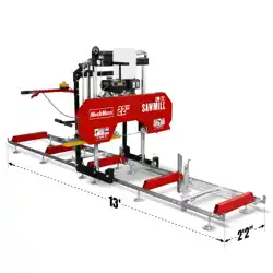
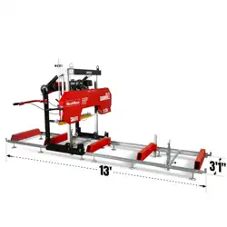
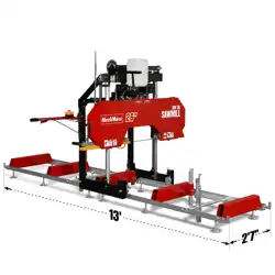
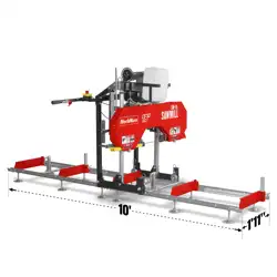
SPECIFICATIONS
Engine
Model
Ducar
SM-18
Engine Type
Single cylinder, 4 stroke, air-cooled, OHV
Engine Displacement
212cc
Horsepower
7 hp
Max Live Edge Width
Log Diameter
Start
15"
18"
Recoil
Standard Cutting Length
8' 1"
Max Board Thickness
6"
Blade Engagement System
Centrifugal Clutch
Cast Iron Bandwheel Diameter
14"
Blade Wheel Engagement
Belt drive
Blade Guide
By roller
Blade Tension
By adjustable lever
Blade Size
108 x 0.7 in
Water lube - manual valve
7/8 in
2.6 gal
22.4 in
10 ft
4 ft 9 in
12
4
2x Quick Lock
1.2*3 in
Yes
Powder Coat Paint Galvanized Steel
62*21*30"
335/463 lbs
Blade Lubrication
Blade Pitch
Lubricant Tank Size
Track Width
Track Length
Track Extension Length
Levelling Feet
Log Rests
Log Clamps
Track Bunks
4 Post Head Design
Finish
Packing Size
N.W./G.W.

SAFETY SIGNS
The rating plate on your machine may show symbols. These represent important information about the product or instruc-
tions on its use.
3
www.mechmaxx.com
SAFETY SIGNS
4
www.mechmaxx.com
SAFETY
SAFETY
。Keep work area clean, free of clutter and well lit.
Cluttered and dark work areas can cause accidents.
。Do not use your sawmill where there is a risk of caus-
ing a fire or an explosion; e.g.
In the presence of flammable liquids, gases, or dust .
Power tools create sparks, which may ignite the dust or
fumes.
。Keep children and bystanders away while operating a
power tool. Distractions can cause you to lose control, so
visitors should remain at a safe distance from the work
area.
。Be aware of all power lines, electrical circuits, water
pipes and other mechanical hazards in your work area,
particularly those hazards below the work surface hidden
from the operator’s view that may be unintentionally
contacted and may cause personal harm or property
damage.
。Be alert to your surroundings. Using power tools in
confined work area may put you dangerously close to
cutting tools and rotating parts.
。Stay alert, watch what you are doing and use common
sense when operating a power tool. Do not use a power
tool while you are tired or under the influence of drugs,
alcohol or medication. A moment of inattention while
operating power tools may result in serious personal
injury.
。Dress properly. Do not wear loose clothing, dangling
objects, or jewelry. Keep your hair, clothing and gloves
away from moving parts. Loose clothes, jewelry or long
hair can be caught in moving parts. Air vents often cover
moving parts and should be avoided.
。Use safety apparel and equipment. Use safety goggles
or safety glasses with side shields which comply with
current national standards, or when needed, a face shield.
Use as dust mask in dusty work conditions. This applies
to all persons in the work area. Also use non-skid safety
shoes, hardhat, gloves, dust collection systems, and
hearing protection when appropriate.
。Do not overreach. Keep proper footing and balance at
all times.
。 Remove adjusting keys or wrenches before connecting
to the power supply or turning on the tool. A wrench or key
that is left attached to a rotating part of the tool may
result in personal injury.
。Never make blade guide adjustments, remove or install
blades or conduct any other maintenance or make any
other adjustments when the engine is running.
。Always be sure operator is familiar with proper safety
precautions and operation techniques before using
machine.
。Avoid “kick-back” by knowing what conditions can
create it.
。Do not force the tool. Tools do a better and safer job
when used in the manner for which they are designed.
。Never use the sawmill with a malfunctioning switch.
Any power tool that cannot be controlled with the switch
is dangerous and must be repaired before using.
。 Turn off the engine and place the switch in the locked
or off position before servicing, adjusting, installing
accessories or attachments, or storing. Such preventive
safety measures reduce the risk of starting the power
tool accidentally.
。 Secure logs with the log screw clamping device
instead of with your hand or another individual’s help. This
safety precaution allows for proper tool operation using
both hands.
Read and understand all instructions.
Failure to follow all instructions listed
below may result in electric shock, fire
and/or serious injury.
The warnings, cautions, and instructions
discussed in this instruction manual
cannot cover all possible conditions or
situations that could occur.
It must be understood by the operator that
common sense and caution are factors
which cannot be built into this product,
but must be supplied by the operator.
WORK AREA
PERSONAL SAFETY
TOOL USE AND CARE

5
www.mechmaxx.com
SAFETY
。Storing sawmill. When the sawmill is not use, store it
in a dry, secure place or keep well covered and out of the
reach of children. Inspect the sawmill for good working
condition prior to storage and before re-use.
。Maintain your sawmill. It is recommended that the
general condition of the sawmill be examined before it is
used. Keep your sawmill in good repair by adopting a
program of conscientious repair and maintenance in
accordance with the recommended procedures found in
this manual. If any abnormal vibrations or noise occurs,
turn the sawmill off immediately and have the problem
corrected before further use.
。Keep saw blades sharp and clean. Properly maintained
band saw blades are less likely to bind and are easier to
control.
。Cleaning and Lubrication. Use only soap and a damp
cloth to clean your sawmill. Many household cleaners are
harmful to plastic and rubber components on the sawmill.
。Use only accessories that are recommended by the
manufacturer for your model. Accessories that may be
suitable for another sawmill may create a risk of injury
when used on the sawmill.
。Always operate machine with all safety devices and
guards in place and in working order. DO NOT modify or
make changes to safety devices. DO NOT operate
machine if any safety devices or guards are missing or
inoperative.
。Never leave sawmill running unattended.
。Coiled blades can spring apart with considerable force
and unpredictably in any direction. Always deal with coiled
blades, including those packaged in boxes, with the
utmost care.
。Never use the equipment to cut anything other than
lumber or for any purpose other than cutting lumber as
described in this manual.
1. Wear heavy-duty work gloves, ANSI-approved goggles
behind a full face shield, steel-toed work boots, and a
dust mask.
2. Operate only with assistance.
3. Ensure guide blocks are tight and track is level.
4. Fill the lubrication tank with clean water and dish soap
(or dishwashing liquid).
5. Start and operate the engine.
6. Cut branches off the lumber to be processed.
7. WARNING: To avoid death or serious injury, Do not cut
lumber with foreign objects in it such as nails, any metal
pieces, etc.
8. Place the lumber to be cut on the supports.
9. WARNING: The operator and any assistants must stay
clear of the front and back of the blade whenever the
engine is ON.
10. Move the saw head slowly along the track and against
the lumber to make the cut.
11. Trim off the rounded sides of the log.
12. When the log is squared-off, boards or posts can be
cut to custom specifications.
Proper and routine maintenance is critical to operator
safety, achieving good milling results and to prolonging
the life of your investment.
1. Band Wheel Bearings --- Should be inspected before
use to ensure they are not worn. Bearings are sealed and
do not need to be greased.
2. Blade Guide Bearings --- Inspect before use for exces-
sive grooves or scoring in the bearings case. Replace if
necessary.
3. Blade Tension: Grease the threads of tensioning “T”
handle when dry or as required. Use multi-purpose,
extreme-pressure grease.
4. Log Screws --- Grease frequently.
5. Belts: Periodically check the condition and wear of the
drive and idler belt. Ensure that the blade does not ride on
the bandwheels.
6. Drive Belt --- Periodically check the tension of the drive
belt. It should deflect no more than 1/2”.
7. Sawhead Locking Cam Handles --- Grease assembly
every 30 days or as required.
8. Sawhead Vertical Posts --- Spray posts before use with
a silicone spray lubrication such as 3-in-1 or Jig-A-Loo.
9. Bandwheel Guards: Routinely remove any build-up of
sawdust that may collect inside the bandwheel guards.
10. Lubrication Tank --- Only fill with a water/washing up
detergent mixture (one to two caps) or in winter months,
use windshield washer fluid. Do not leave lubricant in tank
if temperatures fall below 0°C (32°F).
START UP PROCEDURE – EQUIPMENT
OPERATION
GENERAL MAINTENANCE INFORMATION

6
www.mechmaxx.com
SAFETY
11. Blade Lubricant: Never use diesel fuel or kerosene as
blade lubricant. These substances lead to premature
wear of your belts and poor sawing performance. For
winter operations, replace the water lubricant with wind-
shield washer fluid.
12. Sawhead Lifting Cables: Regularly before, during and
after operations, inspect the cables for any wear or kinks.
Ensure that the cables are in perfect condition. Oil coiled
part of cable often to prevent premature wear. Replace
with new cables as necessary.
7
www.mechmaxx.com
ASSEMBLY
ASSEMBLY
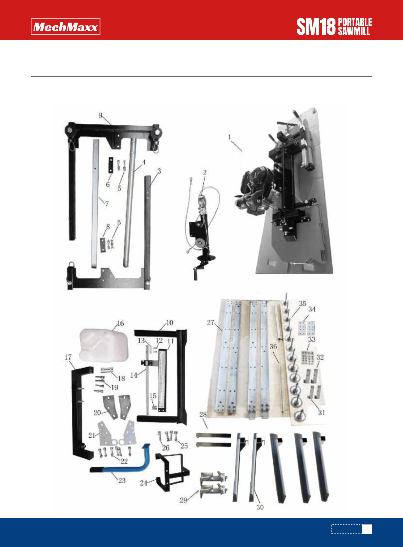
A. Take all of the parts out of the shipping crate and lay them out.
PARTS INSPECTION

8
www.mechmaxx.com
ASSEMBLY
PARTS CHECKING LIST
NO. Qty.DESCRIPTION NO. DESCRIPTION Qty.
SAW HEAD
STEEL ROPE HOLDER COMPLETE
LEFT VERTICAL FRAME
ROUND SUPPORT
SPACER PLATE C
SQUARE POST
SPACER PLATE B
RIGHT VERTICAL FRAME
STRENGTHEN BRACKET
SCALE BRACKET(WITH SCALE)
SPACER BLOCK
POINTER COMPLETE STOPPER NO.2
STOPPER NO.1
CROSS ARM ASM
MOVABLE CLAMP ASM
14
13
12
11
10
9
32
31
30
29
FIXED CLAMP ASM
28
GUIDE RAIL
27
8
7
6
26
25
24
5
4
3
2
1 1
1
1
1
1
1
1
1
1
1
1
1
2
2
4
4
4
4
4
4
2
2
1
1
4
6
12
6
6
2
4
2
2
2
2
2
4
2
2
2
2
5
23
22
21
20
19
HEX BOLT M6X25
WASHER 6mm
HEX BOLT M12X70
WASHER 12mm
SPRING WASHER 12mm
HEX NUT M12
HEX BOLT M10X65
WASHER 10mm
SPRING WASHER 10mm
HEX BOLT M10X65
WASHER 10mm
SPRING WASHER 10mm
HEX NUT M10
HEX BOLT M10X70
WASHER 10mm
SPRING WASHER 10mm
HEX BOLT M10
HEX BOLT M10X55
WASHER 10mm
SPRING WASHER 10mm
SUPPORT POST FOR TANK
PUSH-PULL HANDLE
JOINT PLATE A
JOINT PLATE B
9
www.mechmaxx.com
ASSEMBLY
TRACKS ASSEMBLY
Assemble track system and secure loosely with provided nuts and bolts. It is important not to fully tighten the bolts at
this stage. This will be done after the head is assembled and rolled along the track. It is ideal to assemble the tracks on
a solid and level footing that is a minimum of 4" off the ground - We recommend you attach the leveling legs to support
beams (sleepers) which we discuss later in the instruction manual. This will allow for easy cleanup of sawdust from
under the tracks and height adjustment of the log supports and also easier leveling of the track.
1
2
2
2
48
48
4
4
2
2
12
1
1
NO. Qty.DESCRIPTION NO. DESCRIPTION Qty.
COOLANT TANK WITH PLASTIC TUBE
JOINT BRACKET WITH BOLTS
SPACER PLATE A18
17
16
15
36
35
34
33
SLIDING BAR
FOOT PAD WITH NUT & WASHER
JOINT PLATE
HEX BOLT M8X16
WASHER 8mm
HEX NUT M8
HEX BOLT M10X25
HEX NUT M10
HEX BOLT M12X25
WASHER 12mm
10
www.mechmaxx.com
ASSEMBLY
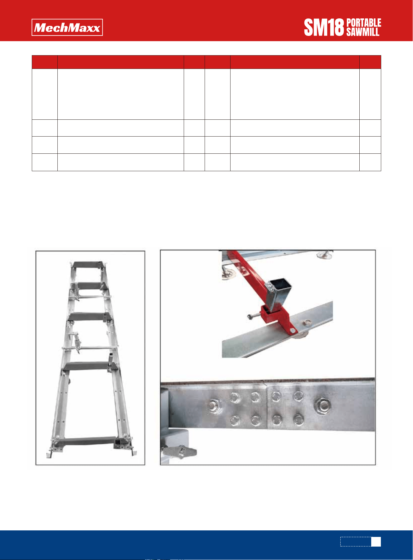
LOG DOG & SUPPORTS
Attach track cross supports to "L" channel with the provided nuts & bolts. The joining plate is used at the seam joint to
join the two sections together (shown in top right image). Ensure to only hand tighten at this stage. The bolts will be
fully tightened once the head assembly is free to roll on the tracks and provide the correct track width.
Assemble log dog pieces as shown below and use waterproof grease on threaded handle and “T” handle. Attach assembly
to the track using the provided nuts & bolts and tighten.
Attach log dog assembly to track as shown below with 2 bolts and washers provided. Note that there are various
locations along the track where this assembly can be bolted. Depending on how many track sections are being used,
select a log clamp position that will secure the log firmly against the log supports.
Assemble carriage stops at the ends of the tracks (4 stops total) and tighten.
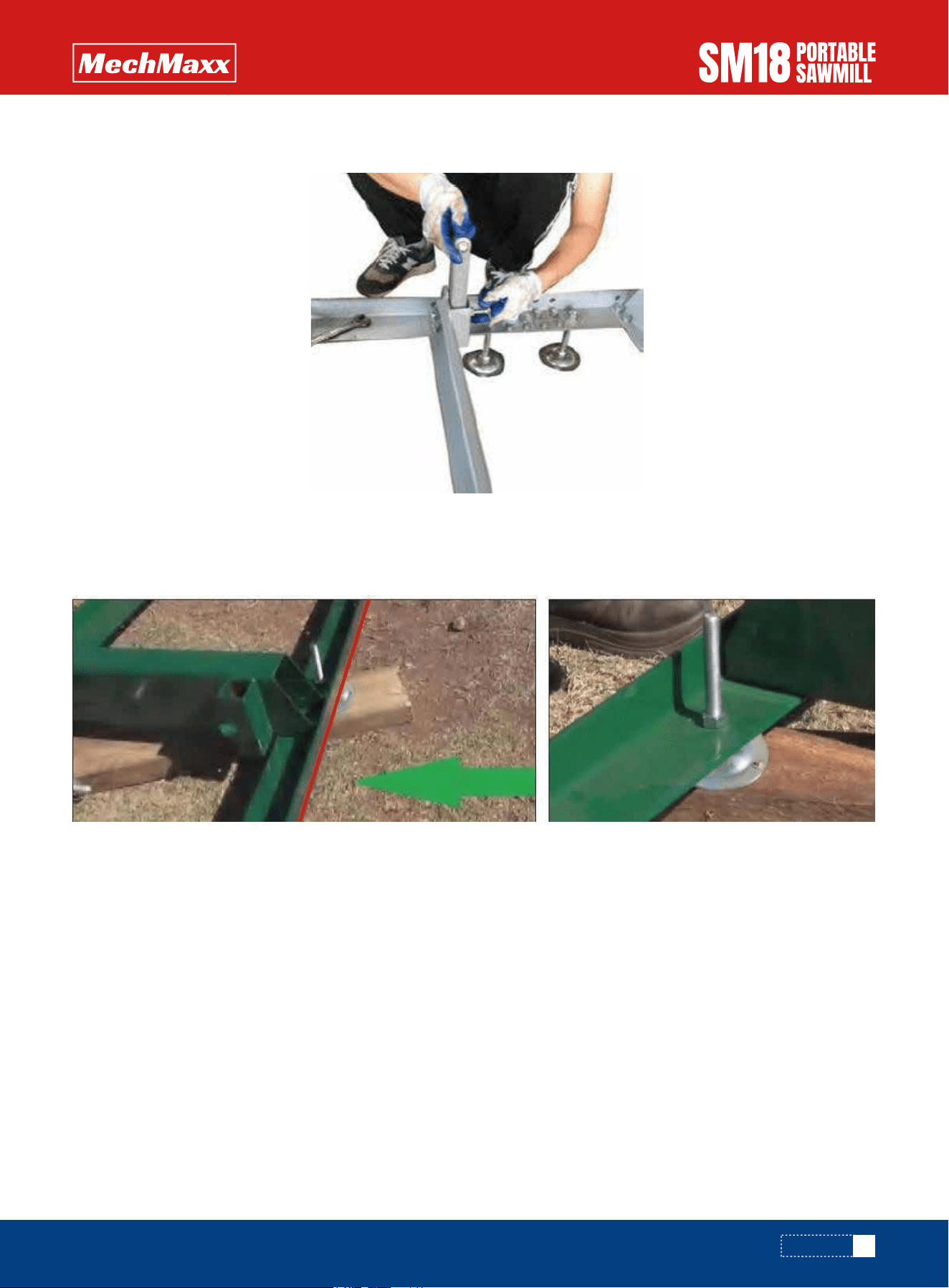
11
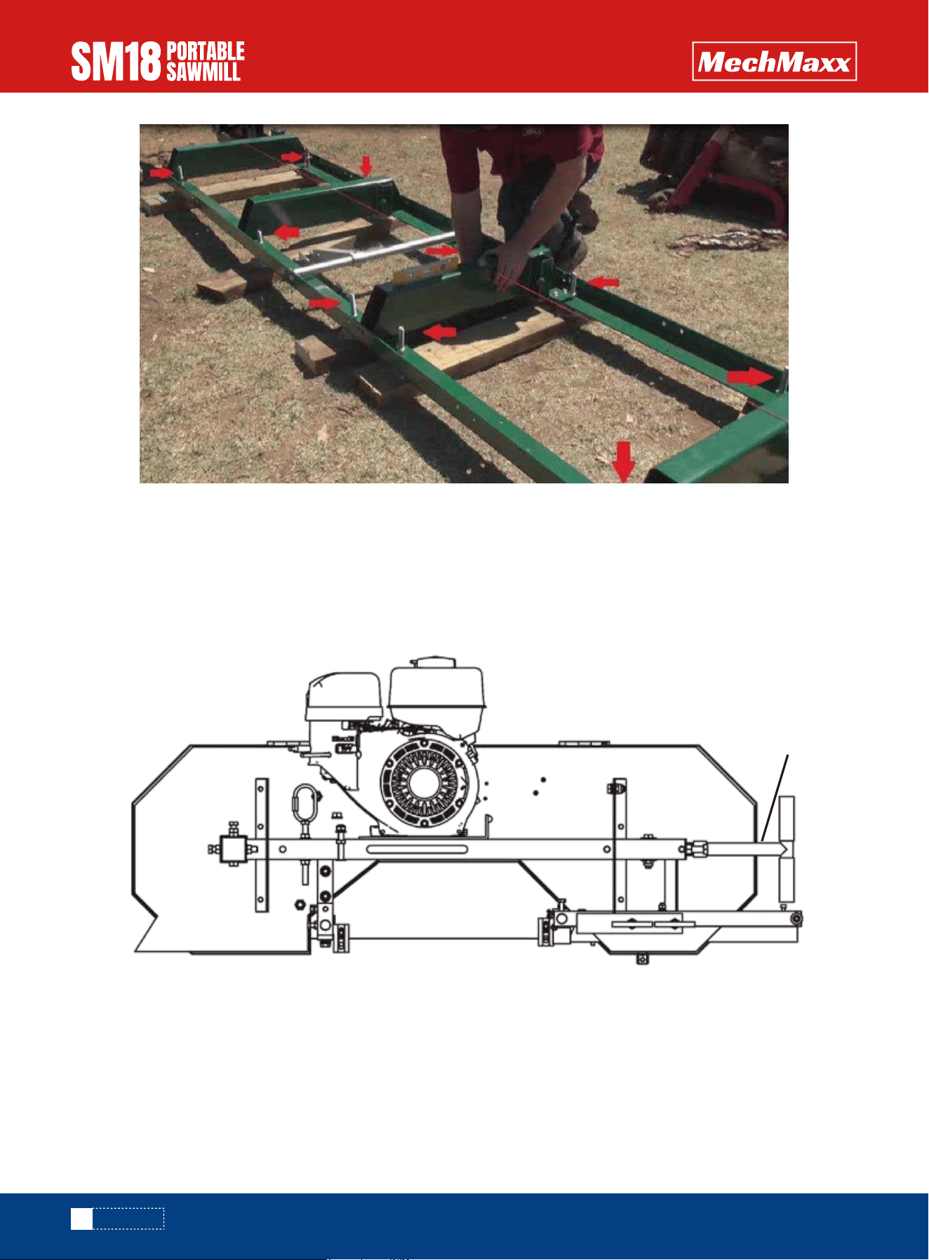
www.mechmaxx.com
ASSEMBLY
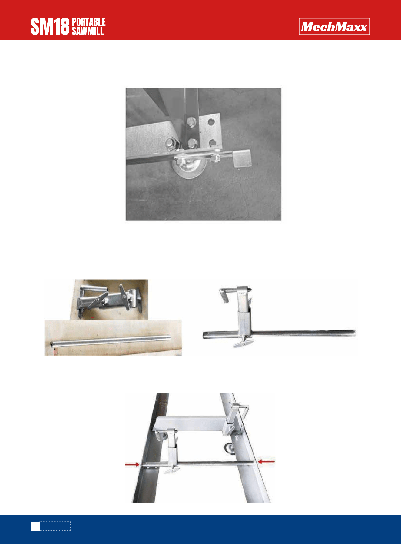
Ensure Track Cross Arms are Level
Note:
If the ground is not a hard surface and not level, you can insert some wood blocks under the track.
Insert log supports into track cross supports and secure with “T” handles. The “T” handle thread should be coated with
waterproof grease.
We recommend fastening with self-tapping screws (tech screws) the leveling legs to sleepers once the mill has been
made level. So before fastening screwing the mill to the sleepers, it is highly recommended that you run a string line down
both sides of the mill, to make sure the track is straight and level.
The red arrows indicate the locations of the leveling legs are. There are six per 1.5 meters (approx. 5 feet) of track, 12 in
total on the machine. On the intermediate bunks the leveling legs alternate. We recommend placing the mill leveling legs
on sleepers running left to right as shown above. You need to make sure the bunks are also level. To do this you use a level
going left to right on top of each bunk and also using a string line down the length of the track. The string line needs to
be approx. 10mm (3/8 inch) above the bunks.
12
www.mechmaxx.com
ASSEMBLY
Carriage assembly
Place a moving blanket on the shipping pallet that the sawmill crate was strapped to. The blanket will prevent the blade
guard covers from becoming scratched. Using a minimum of two people or a mechanical advantage system, remove the
head assembly from the sawmill crate and place face down on the blanket. The head assembly is very heavy, proper
technique must be used to avoid injury or damage.
Find the square and round columns, and insert the round one into the sliding tube close to blade tension system, and
insert square one into the sliding tube on the other side, and secure the two vertical posts using the locking handle.
Attention to the stop bolt on the square column.
Blade tension
13
www.mechmaxx.com
Square columnLocking handle
Round columnSliding tubeStop bolt
Sliding tube
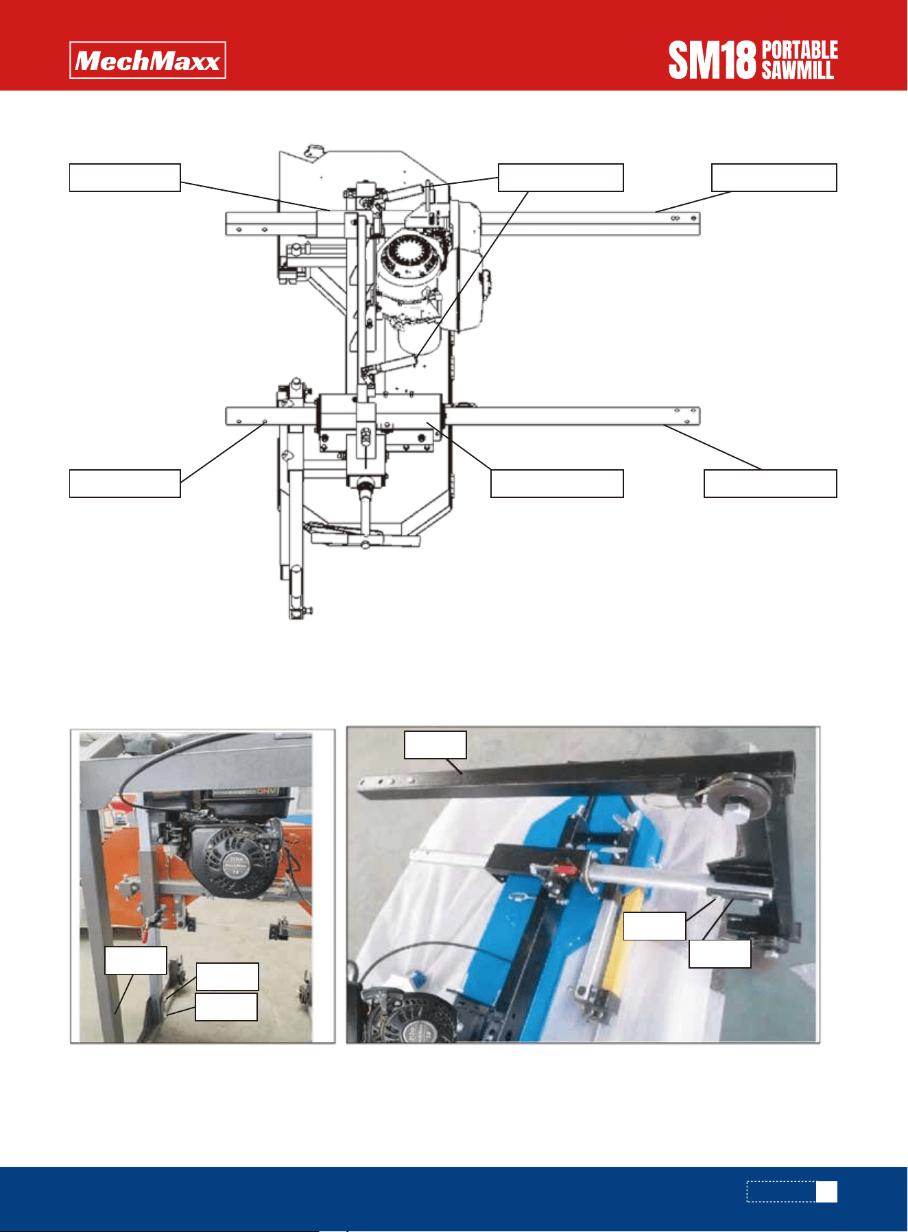
Connect the Left vertical frame (3) to the Square column as shown by bolts (5) and Space Plate В (8). And then connect
the Right vertical frame (9) to the Round column by bolts (5) and Space Plate C (6).
ASSEMBLY
3
5
8
9
5
7
14
www.mechmaxx.com
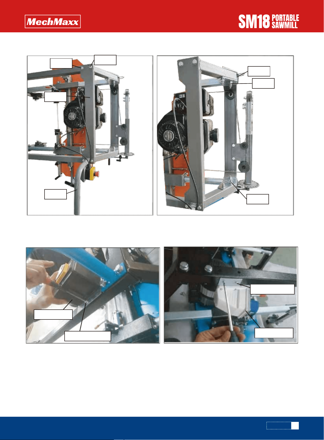
Connect the Joint bracket (17) to the Square column and Round column by bolts (19) and Space Plate A (18). Loosen the
bolts and nuts on the Joint bracket, and fix the Steel rope holder as picture showing.
Loosen the Chain nut on machine head, Route the steel rope over the pulley, attach the two ends of the steel rope to the
holders, tighten the Chain nut. Swing the Lift handle to to tighten the steel rope. Lock the Locking handles.
ASSEMBLY
19
17
18
19
Rope-1
2
Bolts
and nuts
Rope-2
Chain nut
Steel rope
Steel rope
Lift handle
Locking handle
15
www.mechmaxx.com
Connect the Strengthen Bracket (10) and Push-pull handle (23) by parts supplied (25, 26, 20, 21,22).
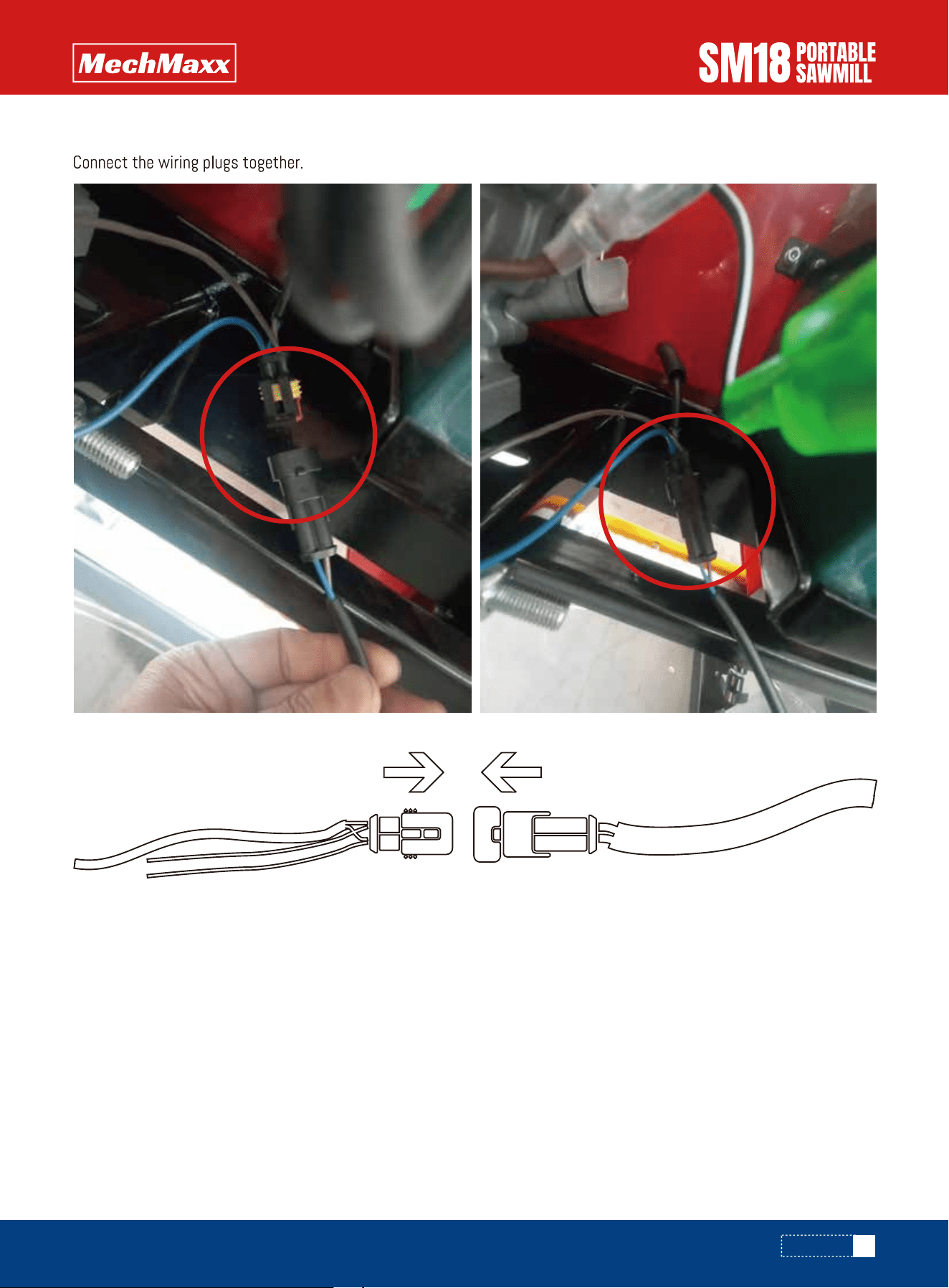
Loosen two Pan head screws and install the Power switch on the Right vertical frame. Loosen two Pan head screws on
the Left vertical frame and secure the Plug Assembly.
ASSEMBLY
Power switch
Pan head screw
Plug asm
Pan head screw
26
10
23
25
22
20
21
16
www.mechmaxx.com
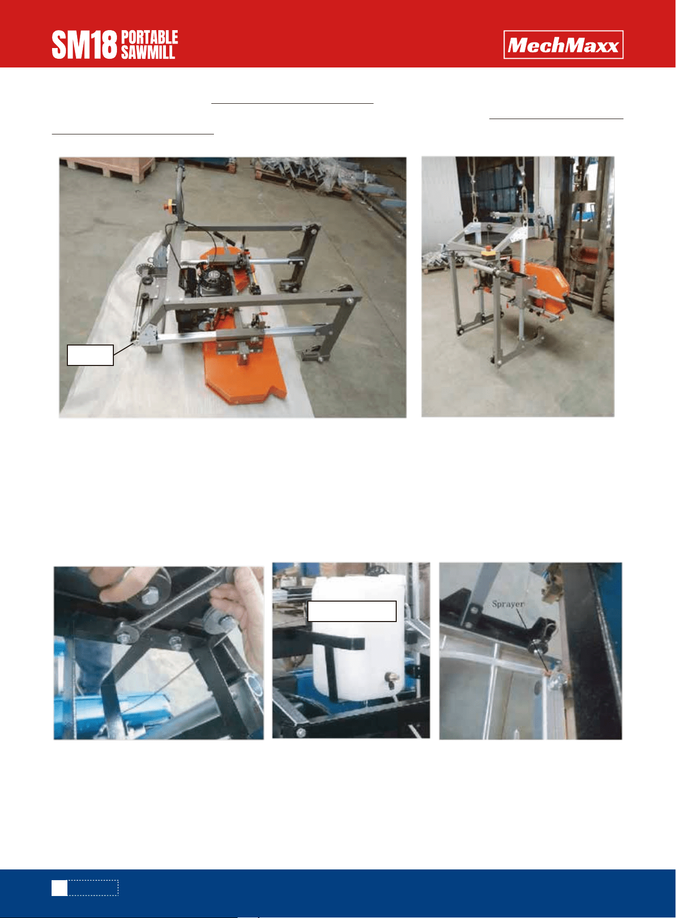
After carriage assembly on pallet, lift the machine carriage by forklift to make it stand up and put it onto the track system,
ensure the grooves of four wheels well fit the rails of track and move smoothly on the track. If no forklift at working area,
at least two people are necessary to make the machine carriage stand up and put it on the track.
Push the machine carriage forward and back along the track system to ensure that the width of the track allows for the
saw head to move freely. If it binds, the "L" rails will need to be set further or closer together to achieve a consistent
width along the entire track system. Once the desired width is achieved, all nuts and bolts can be tightened to the log
bunks.
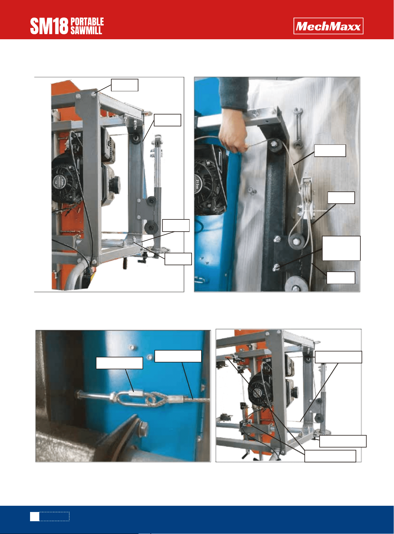
Assemble coolant system at back side of Joint bracket, please note that the two bolts securing the Steel Rope Holder
need to be reused, firstly only take off two nuts and washers and mount the Support post for tank and then tighten two
nuts, must be careful during the time of assembly. And then put the plastic tank into the Support post, finally connect the
water tube from Liquid tank to Sprayer mounted on the blade guide.
Note: We recommend adding some dishwashing liquid to the tank to help lubricate the wood — two to three capfuls.
ASSEMBLY
21
Liquid tank
17
www.mechmaxx.com
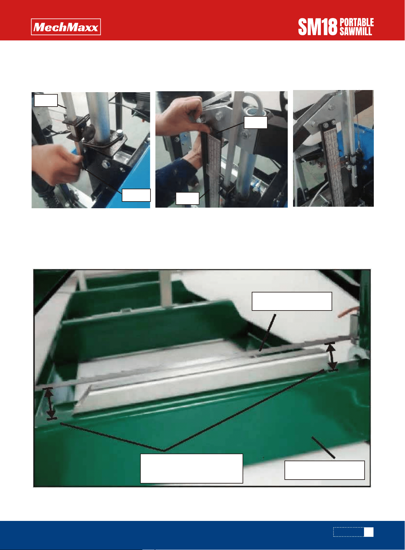
Find the Pointer complete (14) and Scale bracket (11), Install the Pointer Assembly (14) at the right side of Sliding tube
on the Saw head, use these parts supplied (12, 13). Attach the Scale Bracket (11)at the right side of Joint plate A, use
the bolts and nuts (15). Finally tighten all the bolts.
Using a tape measure, take a measurement at left and right side from the blade to the top of the cross arm. If there is no
tape measure in the hand, one steel tube can be put onto the top side of the cross arm to check the distance at both
sides. The distance should be equal at both sides. If it isn't equal, the height of left or right side of saw head can be
adjusted by adjusting the tension of steel rope, and then turning the lift handle to move the saw head slightly up and down
to balance the saw head. Finally, ensure the saw blade is parallel to the top surface of the cross arm.
ASSEMBLY
14
14
14
12.13
Saw blade
Cross arm
Check distance
at two sides
18
www.mechmaxx.com
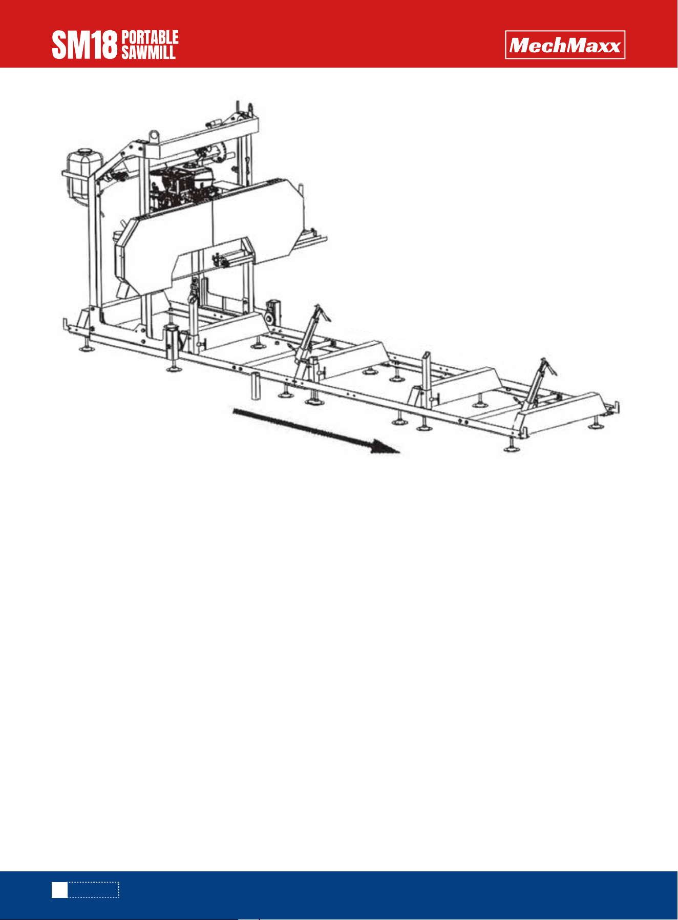
ASSEMBLY
Right side of mill
Left side of mill
Notice: Always cut in the direction shown above. The log clamp should always be at the right side of the log and the log
supports should always be at the left. Failure to cut in this direction can cause the log to come loose and possibly even
cause damage or injury.
Now that your sawmill is assembled, please run through the "SAWMILL SET-UP PROCEDURES" in the following section.
Failure to do so may result in poor sawing performance, damage or injury. See next page.*
19
www.mechmaxx.com
ELECTRICAL DIAGRAM
ASSEMBLY
20
www.mechmaxx.com
SAWMILL SET-UP PROCEDURES
BELT TENSION
BLADE TRACKING
Forward Direction
Rearward Direction
SAWMILL SET-UP PROCEDURES
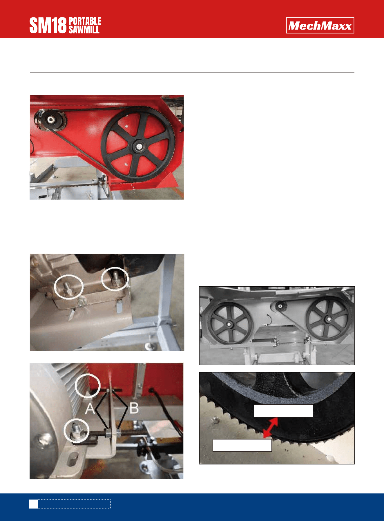
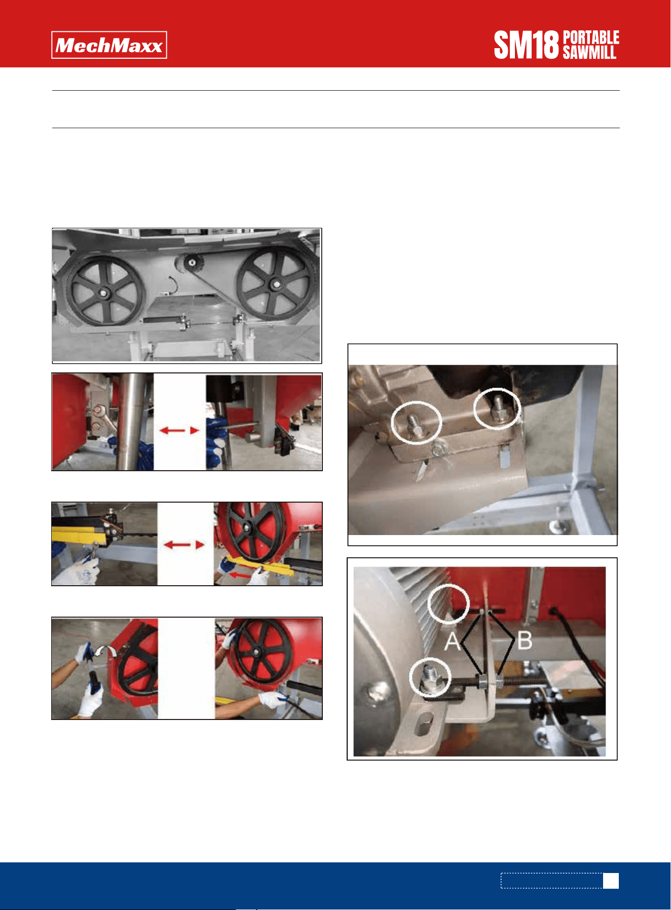
To check the belt tension, with your hand, firmly try to
deflect the belt up and down. There should be no more
than 1/4" of deflection in both directions (1/2" total). If
the belt deflects more than this, it will need to be tight-
ened as described below.
To change the drive side belt, loosen the four bolts that
secure the engine to the engine mount using a 16mm
(approx. 5/8") wrench.
Now that the motor is free to slide on the motor mounting
plate, turn the 13mm (approx. 1/2") nut (A) on the
horizontal stud in the counterclockwise direction, push
the motor towards the stud and apply more tension on
the belt. Do this step incrementally while checking the
belt for proper deflection. It is also important to ensure
that the motor remains perpendicular to the drive belt.
Overtightening can cause the motor to twist on the
mounting plate, resulting in belt alignment issues and
premature wear. Once the desired belt tension is set,
tighten the four engine bolts. Alternatively, if the drive
belt is too tight, turn the 13mm (approx. 1/2") nut(B) on
the horizontal stud counterclockwise direction, push the
motor away from the stud.
Never attempt the following procedures when the engine
is running. As a safety precaution, remove the spark plug
cap. It is also advised to wear gloves and safety glasses
when working with the blades as it is extremely sharp.
21
www.mechmaxx.com
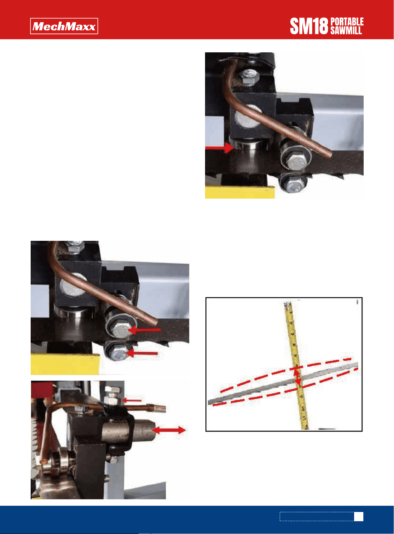
ADJUSTING THE RIGHT HAND SIDE
SAWMILL SET-UP PROCEDURES
The blade should run with the same tooth to bandwheel
face distance on both sides. Measure the distance from
the tip of the blade tooth to the front face of the band-
wheel on both sides. If an adjustment on either side is
required, the below steps will detail this procedure.
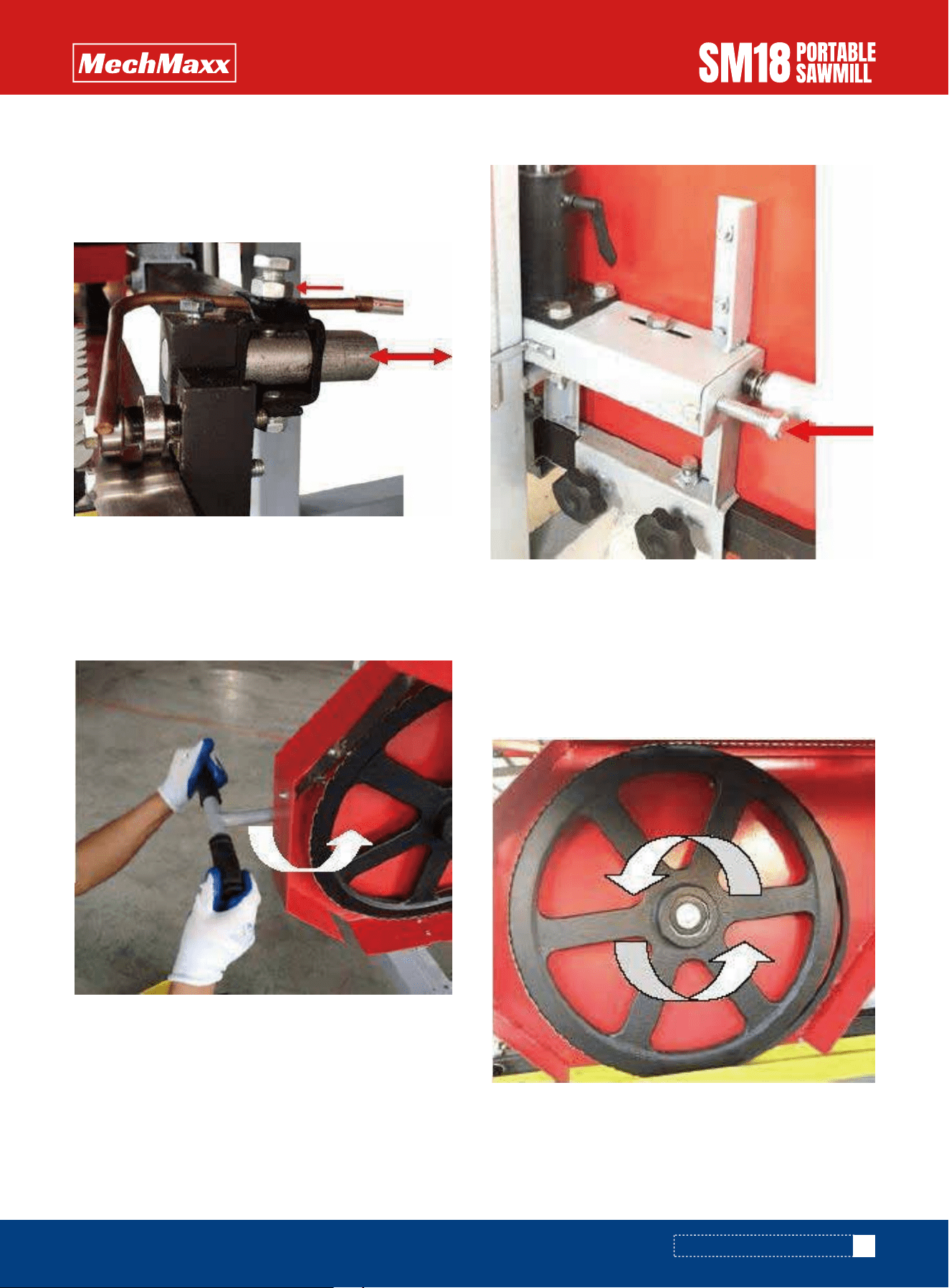
Loosen the blade guide assembly bolt with a 13mm
(approx. 1/2") socket. The round shaft should now be free
to slide rearward and out of the way. Perform this step on
both guide assemblies. This will ensure that the guide
bearings do not influence tracking of the blade while
adjusting.
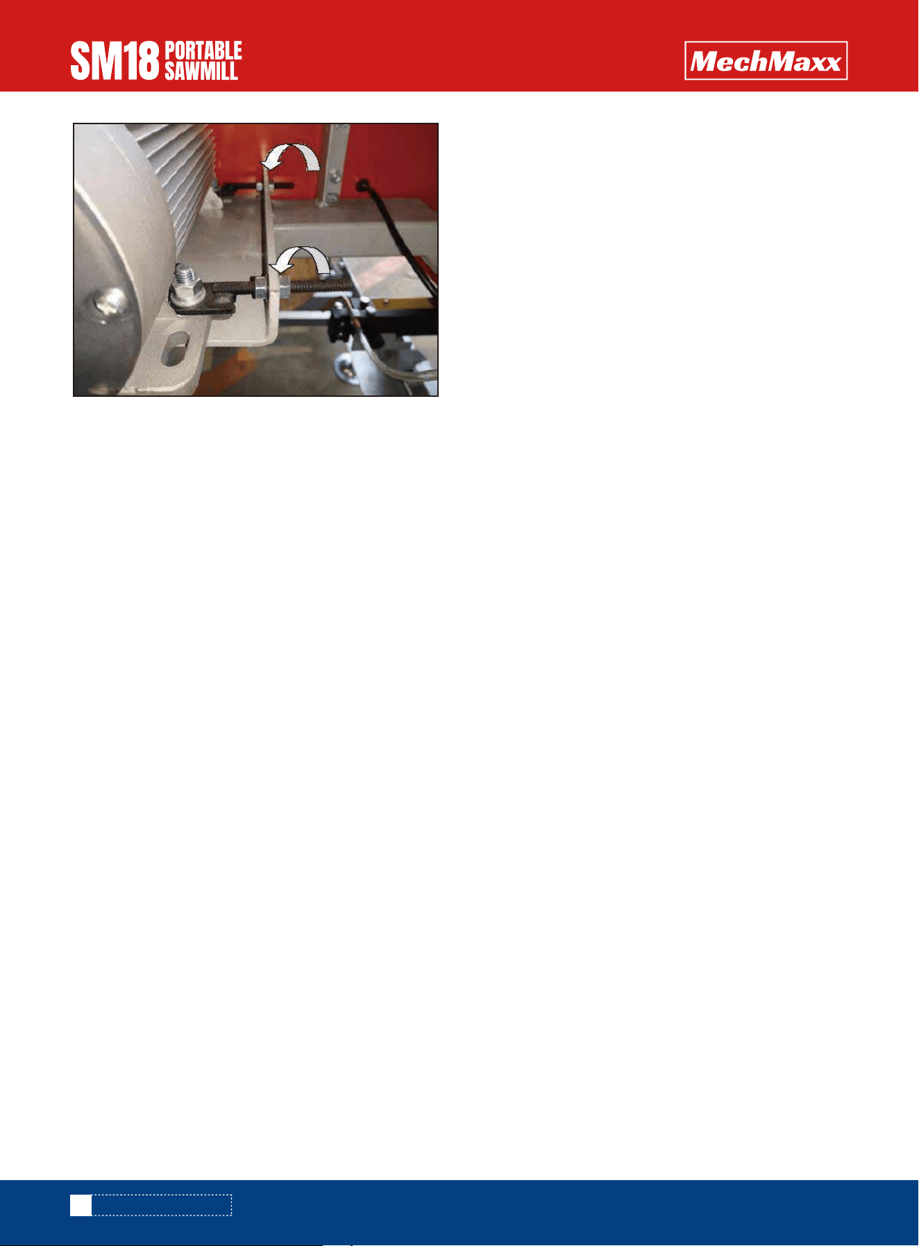
Loosen the tracking alignment bolt with an adjustable
wrench. The alignment bolt can now be turned to change
the angle of the bandwheel and track the blade. To move
the blade more rearward on the bandwheel, this bolt will
need to be turned clockwise. Alternatively, turning the
bolt in the counter-clockwise direction would force the
blade to run more forward on the bandwheel.
Take some tension off of the blade by turning the "T"
handle in the counter-clockwise direction one full turn
from full tension position.
Wearing gloves, spin the bandwheel with your hand and
observe how the blade has changed tracking. Measure the
distance again and repeat the above step to further
compensate if required
To adjust the left side of the sawmill, again start by
taking the tension off of the blade by turning the “T”
handle one turn in the counter-clockwise direction. Using
a 16mm (approx. 5/8") wrench, loosen both “vertical
bolts” a 1/2 turn. This will take the clamping force off of
the bandwheel shaft caused by these two bolts and allow
it to move freely in the following steps.
Using a 16mm wrench, hold the “horizontal bolt” station-
ary with a wrench and turn the “horizontal inside nut”
counter-clockwise a 1/2 turn. Still holding the “horizontal
bolt” stationary, turn the “horizontal outside nut” clock-
wise a 1/2 turn. This has now shifted the “horizontal bolt”
and bandwheel shaft, causing the blade to track more
forward.
22
www.mechmaxx.com
ADJUSTING THE LEFT HAND SIDE
MOVING THE BLADE FORWARD
Using a 16mm wrench, hold the “horizontal bolt” station-
ary with a wrench and turn the “horizontal outside nut”
counter-clockwise a 1/2 turn. Still holding the “horizontal
bolt” stationary, turn the “horizontal inside nut” clockwise
a 1/2 turn. This step has now shifted the “horizontal bolt”
and bandwheel shaft, causing the blade to track more
forward.
Tighten the vertical bolts, then nuts to clamp the band-
wheel shaft into the vertical position.
MOVING THE BLADE REARWARD
Forward Direction
Rearward Direction
Forward Direction
Rearward Direction
Vertical Bolt
Bottom Vertical Bolt
Horizontal
Inside Nut
Horizontal
Bolt
Horizontal
Outside Nut
SAWMILL SET-UP PROCEDURES
23
www.mechmaxx.com
Re-tension the blade by turning the “T” handle a full turn in
the clockwise direction. Wearing gloves, spin the band-
wheel with your hand and observe how the blade has
changed tracking. Measure the distance again and repeat
the above step to further compensate if required.
Once the blade is tracking true, bring the blade guide
assemblies back up to the blade. Keep a paper width
distance between the blade guide bearing and the back of
the blade. More information on this set up can be found in
the next section – “BLADE GUIDE ADJUSTMENT”
Loosen the blade guide assembly bolt with a 13mm
(approx. 1/2") socket. The round shaft should now be free
to slide back and forth. Position it so that there is a paper
width gap between the bearing and the back of the blade.
Tighten bolt against the flat on the shaft to secure the
assembly back into position.
Using a piece of paper between the blade and blade guide
blocks, tighten the bearing bolts.
Never attempt the following procedure when the engine is
running. As a safety precaution, remove the spark plug
cap. It is also advised to confirm that the blade is tracking
properly before performing the below. Blade tracking is
covered in the previous page.
Using a 13mm (approx. 1/2") wrench loosen the blade
guide bolt on both the left and right sides. They should be
free to slide up and down.
BLADE GUIDE ADJUSTMENT
BLADE TENSION
SAWMILL SET-UP PROCEDURES
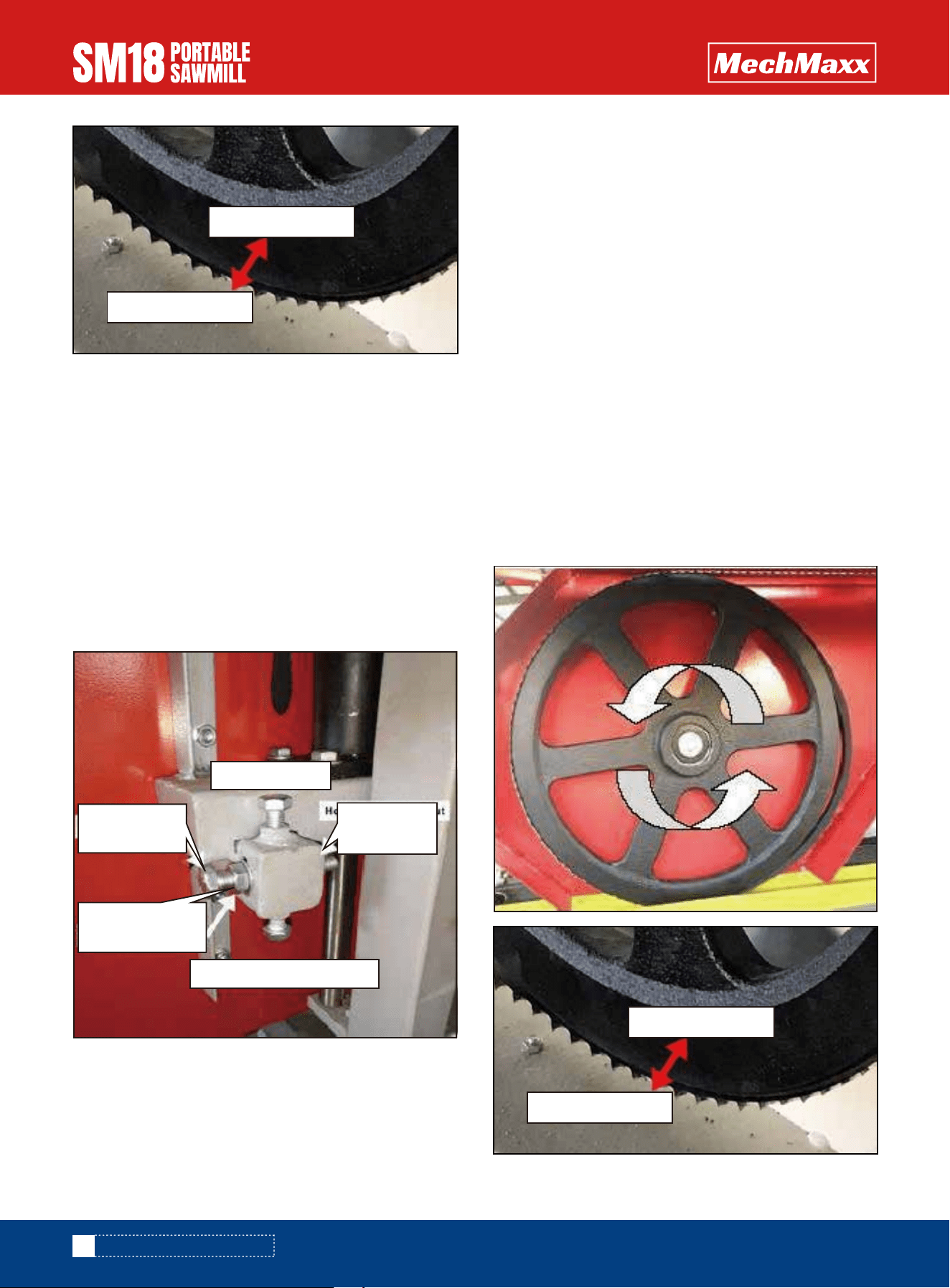
Proper blade tension is achieved when the blade deflects
no more than a total of 1/8” – 1/4” up/down when it is
firmly moved by hand at the center location of the blade
guide blocks. Turning the blade tension “T” handle in the
clockwise direction will add tension to the blade.
When tensioning the blade, make sure the tracking
adjustment bolt sitting behind the “T” handle (pictured) is
sitting back in its recess after you have finished and
before the mill is run. Failure to do this will result in the
blade being thrown and possibly broken.
Tracking adjustment bolt out of recess, If it looks like this
DO NOT start the mill until it is resting back in its recess.
Tracking adjustment bolt sitting in recess. It should look
like this before the mill is started back up.
Ensure the blade support arm is locked into place after
tensioning the blade.
24
www.mechmaxx.com
SAWMILL SET-UP PROCEDURES
25
www.mechmaxx.com
CHANGING THE BLADE REPLACING BELTS
SAWMILL MAINTENANCE
SAWMILL MAINTENANCE
Never attempt the following procedure when the engine
is running. As a safety precaution, remove the power plug.
Gloves and safety glasses must be worn when changing
blade.
Never attempt the below action when the engine running.
As a safety precaution, remove the power plug. Gloves
and safety glasses must be worn when replacing the
belts.
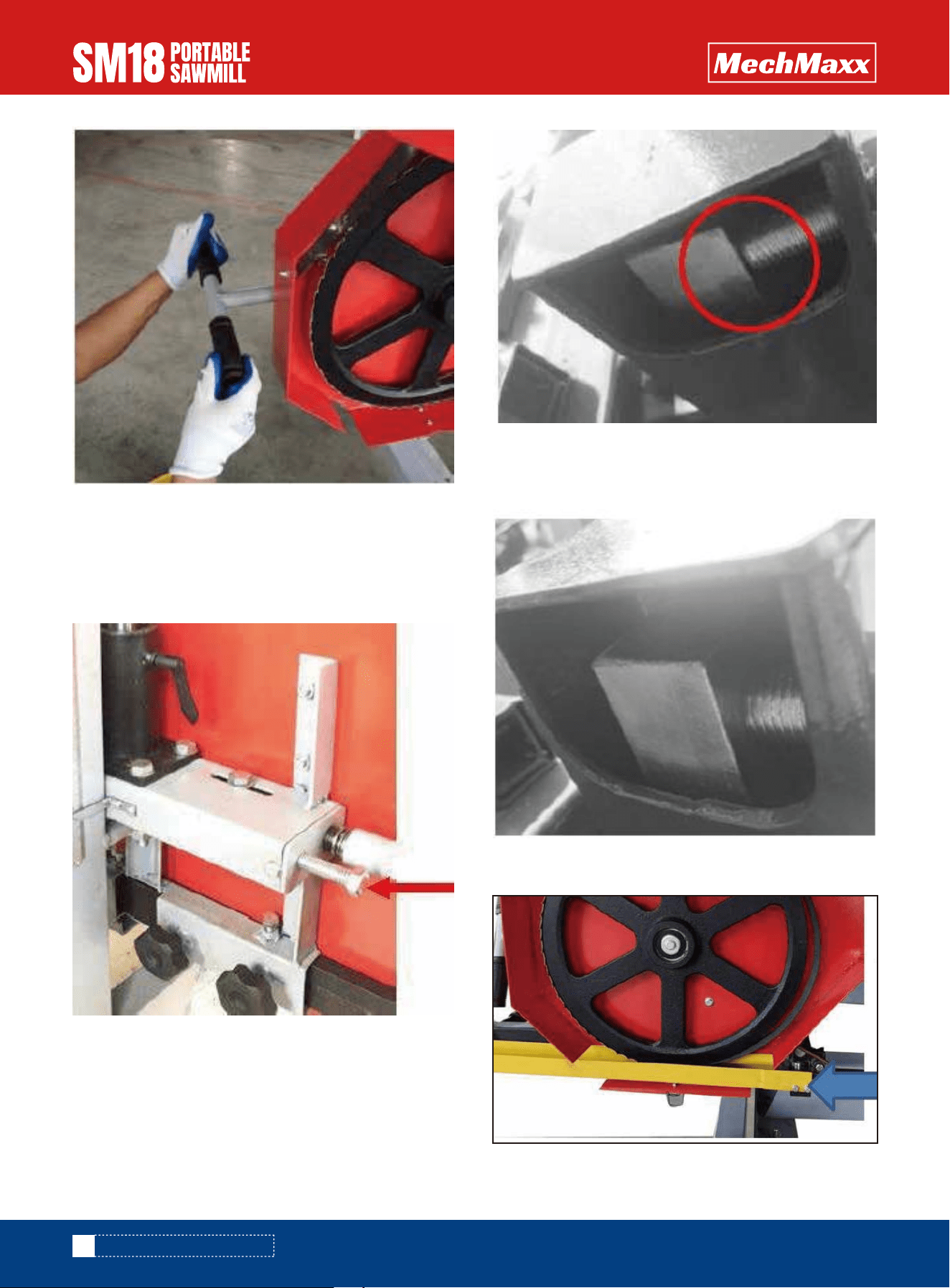
To replace the belts, you first need to remove the blade,
please follow above steps to remove the blade.
There are two rubber V-belts on the sawmill and they
should be replaced as a set. It is not advised to replace
individual belts separately. It is recommended to use a
BX50 cogged belt for the drive side and a BX41 follow
belt.
Remove the tension in the blade by turning the “T” handle
in the counter-clockwise direction. The blade should now
be loose and free to pull straight out the front. The new
blade can now be installed, guards closed and proper
blade tension set.
To change the drive side belt, loosen the four bolts that
secure the engine to the engine mount using a 16mm
(approx. 5/8") wrench.
Loosen the screw and pull back the blade limit lever.
Loosen the screw and pull out the blade guard cover.
26
www.mechmaxx.com
SAWMILL MAINTENANCE
Now the motor is free to slide on the mounting plate, turn
the 13mm (approx. 1/2") nut on the horizontal stud in the
counterclockwise direction. This will allow the motor to
move and will also take the tension off of the belt. The old
belt can be removed and the new belt can be installed.
Tension the new belt and refer to the BELT TENSION
instructions described in the sawmill set up section of
the manual.
The follower belt can now be changed by simply pulling it
off and installing the new one. The blade can now be
re-installed, guards closed and proper blade tension set.
* Note that blade tracking is likely to change and need
adjusting when new belts are installed. Refer to “BLADE
TRACKING” for more information.*
* Note – It is very important to take the tension off of the
blade by turning the “T” handle in the counter-clockwise
direction when the sawmill is not in use. Failure to do so,
will result in flat spots on the rubber belts. These flat
spots will cause the mill to vibrate excessively during
next use.*

27
www.mechmaxx.com
TROUBLESHOOTING
TROUBLESHOOTING
Problem/Issue
Producing wavy cuts.
Last board is tapered or
narrow in middle.
Blade dulls quickly.
Blade comes off of
bandwheels.
Blades are breaking.
Blade is slowing down or
stopping when milling.
1. Inadequate blade tension.
2. Improper blade guide setup.
3. Improper blade tracking.
4. Sap build on blade.
5. Dull blade.
6. Pushing mill too quickly.
1. Tracks are not level.
1. Logs are not clean.
2. Foreign objects in log.
1. Too many blade sharpenings.
2. Inadequate blade tension.
3. Improper blade guide setup.
4. Improper blade tracking.
5. Pushing mill too quickly.
1. Inadequate blade tension.
2. Improper blade guide setup.
3. Improper blade tracking.
4. Belts are worn.
5. Dull blade.
6. Pushing mill too quickly.
1. Inadequate blade tension.
2. Improper drive belt tension.
3. Pushing mill too quickly.
1. Tighten blade. Refer to page 21.
2. Gap between guide blocks and blade is incorrect.
Refer to page 17.
3. Adjust blade tracking. Refer to page 17.
4. Install new blade. Refer to page 22-23. Always use
blade lubricant.
5. Install new blade. Refer to page 22-23
6. Slow feed rate down and push head slower
through log.
1. Tracks need to be checked with level and
adjusted to be square. They also need to be set up
on firm, sturdy ground/base so deflection does not
occur from logs or sawmill head.
1. Logs may contain dirt/sand causing them to wear
prematurely.
2. Tree may contain nails, staples, old fencing etc.
1. Tighten blade. Refer to page 21.
2. Gap between guide blocks and blade is incorrect.
Refer to page 17.
3 Adjust blade tracking. Refer to page 17.
4. Install new belts. Refer to page 24.
5 Install new blade. Refer to page 23.
6. Slow feed rate down and push head slower
through log.
1. Replace blade. Refer to page 23.
2. Binding between guide blocks when blade is too
loose.Tighten blade. Refer to page 21.
3. Gap between guide blocks and blade is incorrect.
Refer to page 17.
4. Adjust blade tracking. Refer to page 17.
5. Slow feed rate down and push head slower
through log.
1. Tighten blade. Refer to page 21.
2. Belts are worn or too loose. Replace. Refer to
page 24.
3. Slow feed rate down and push head slower
through log.
Possible Causes Resolution Options

28
www.mechmaxx.com
TROUBLESHOOTING
Mill is not cutting/cutting
very slowly
Mill is vibrating
excessively
1. Dull blade.
2. Blade is on backwards.
1. Log is not clamped securely.
2. Belts are deformed.
3. Bandwheel bearing issue.
4. Pushing mill too quickly.
5. Loose bolts.
1. Install new blade. Refer to page 23.
2. Remove blade and flip it inside out. The teeth
should be facing in the direction of the log supports.
1. Ensure log is clamped firmly resting on log bunks
and against log supports.
2. Belts may have flats in them from leaving blade
tension tight when not in use. Replace them.
Refer to page 23.
3. Inspect and replace the bandwheel bearings if
worn.
4. Slow feed rate down when milling.
5. Check all bolts to ensure they are tight.
Problem/Issue Possible Causes Resolution Options
29
www.mechmaxx.com
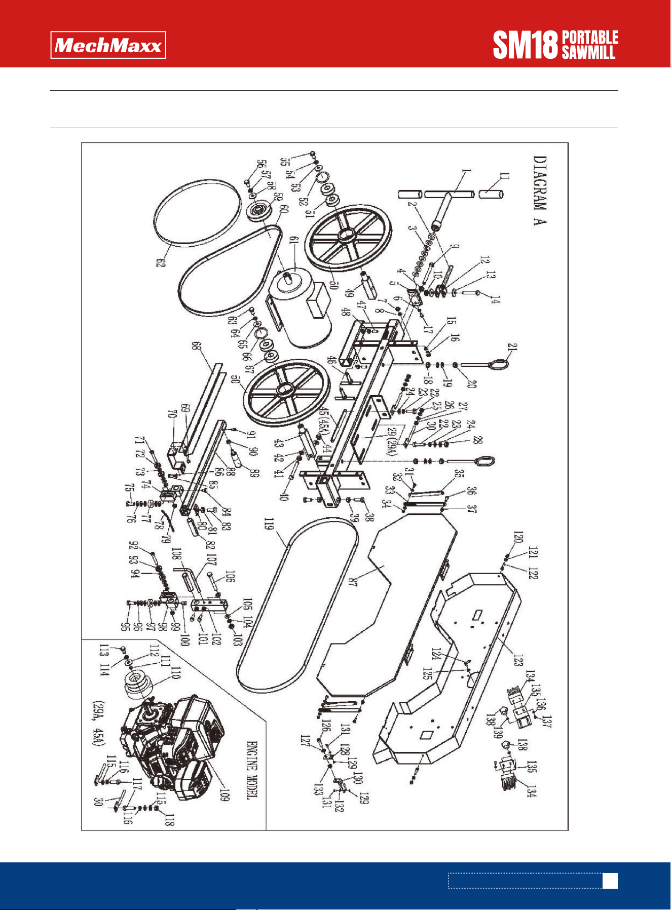
DIAGRAM(A)-BAND WHEEL HOUSING
DIAGRAM(A)-BAND WHEEL HOUSING

30
www.mechmaxx.com
PARTS LIST(A)-BAND WHEEL HOUSING
PARTS LIST(A)-BAND WHEEL HOUSING
NO. DESCRIPTION
A1
A2
A3
A4
A5
A6
A7
A8
A9
A10
A11
A12
A13
A14
A15
A16
A17
A18
A19
A20
A21
A22
A23
A24
A25
A26
A27
A28
A29
TENSION HANDLE
THRUST BALL BEARING
DISC SPRINGS
HEX NUT M12
END CAP FOR MAIN TUBE
WASHER 6mm
HEX NUT M8
WASHER 8mm
HEX BOLT M12X100
HEX LOCK NUT M10
HANDLE COVER
TENSION PLATE
BIG WASHER 10mm
HEX BOLT M10X60
WASHER 8mm
HEX NUT M8X16
HEX BOLT М6X12
HEX NUT M10
WASHER 10mm
HEX NUT M10
LIFT RING
HEX BOLT M10X35
SPRING WASHER 10mm
WASHER 10mm
HEX NUT M8
WASHER 8mm
HEX NUT M8
HEX NUT M10
MAIN BEAM
NO. DESCRIPTION
A30
A31
A32
A33
A34
A35
A36
A37
A38
A39
A40
A41
A42
A43
A44
A45
A46
A47
A48
A49
A50
A51
A52
A53
A54
A55
A56
A57
A58
HEX NUT M8
HEX BOLT M5X16
WASHER 5
BRACKET PLATE No.2
HEX LOCK NUT M5
BRACKET PLATE No.1
HEX BOLT M6X16
HEX LOCK NUT M6
HEX BOLT M10X30
HEX NUT M10
HEX BOLT M10X80
HEX NUT M10
WASHER 10mm
SHAFT FOR DRIVE WHEEL
HEX NUT M10
HEX BOLT M10X80
LOCK SCREW
SET SCREW M8
HEX NUT M8
SHAFT FOR IDLE WHEEL
SAW WHEEL
BEARING 6304
CIRCLIP FOR HOLE
BIG WASHER 10mm
SPRING WASHER
HEX BOLT M10X20
HEX BOLT M10X20
SPRING WASHER
BIG WASHER 10mm

31
www.mechmaxx.com
PARTS LIST(A)-BAND WHEEL HOUSING
NO. DESCRIPTION
A59
A60
A61
A62
A63
A64
A65
A66
A67
A68
A69
A70
A71
A72
A73
A74
A75
A76
A77
A78
A79
A80
A81
A82
A83
A84
A85
A86
A87
A88
A89
MOTOR PULLY
V-BELT BX50
MOTOR
V-BELT BX42
HEX BOLT M10X20
SPRING WASHER
BIG WASHER 10mm
CIRCLIP FOR HOLE
BEARING 6304
FRONT GUARD
HEX BOLT M6X8
GUARD SEAT
ALLEN SCREW M8X50
BEARING 508
WASHER 8mm
GUIDE BLOCK FRONT
HEX BOLT M10X25
WASHER 10mm
BEARING 6200
COOLING TUBE
HEX LOCK NUT M8
CLAMP PLATE
HEX NUT M8
GUIDE SHAFT
HEX BOLT M8X25
HEX BOLT M8X12
HEX BOLT M6X12
WASHER 6mm
SAW BLADE
GUIDE PIPE
HANDLE
NO. DESCRIPTION
A90
A91
A92
A93
A94
A95
A96
A97
A98
A99
A100
A101
A102
A103
A104
A105
A106
A107
A108
A109
A110
A111
A112
A113
A114
A115
A116
A117
A118
A119
A120
HEX NUT M10
ALLEN SCREW M6X8
ALLEN SCREW M8X50
BEARING 608
WASHER 8mm
HEX BOLT M10X25
WASHER 10mm
BEARING 6200
GUIDE BLOCK REAR
HEX LOCK NUT M8
HEX BOLT M8X12
HEX BOLT M8X20
GUIDE TUBE
HEX NUT M10
SPRING WASHER
WASHER 10mm
HEX BOLT M10X80
LOCK HOOK
GUIDE SHAFT
ENGINE
CLUTCH
BUSH
BIG WASHER
HEX BOLT
SPRING WASHER
WASHER 8mm
SPRING WASHER
HEX BOLT
HEX NUT M8
SAW BLADE
HEX CAP NUT M6

32
www.mechmaxx.com
PARTS LIST(A)-BAND WHEEL HOUSING
HEX NUT M6
ALLEN SCREW M6X25
PROTECTIVE COVER
HEX BOLT M6X12
WASHER 6mm
ALLEN SCREW M8X30
WASHER 8mm
LOCK BLOCK NO.1
HEX NUT M4
LOCK BLOCK NO.2
PAN HEAD SCREW M4X10
WASHER 4mm
HEX LOCK NUT M8
BRUSH
BRUSH SEAT
WASHER 4mm
TAP SCREW ST4.2X13
HANDLE M5X10
WASHER 5mm
NO. DESCRIPTION
A121
A122
A123
A124
A125
A126
A127
A128
A129
A130
A131
A132
A133
A134
A135
A136
A137
A138
A139
33
www.mechmaxx.com
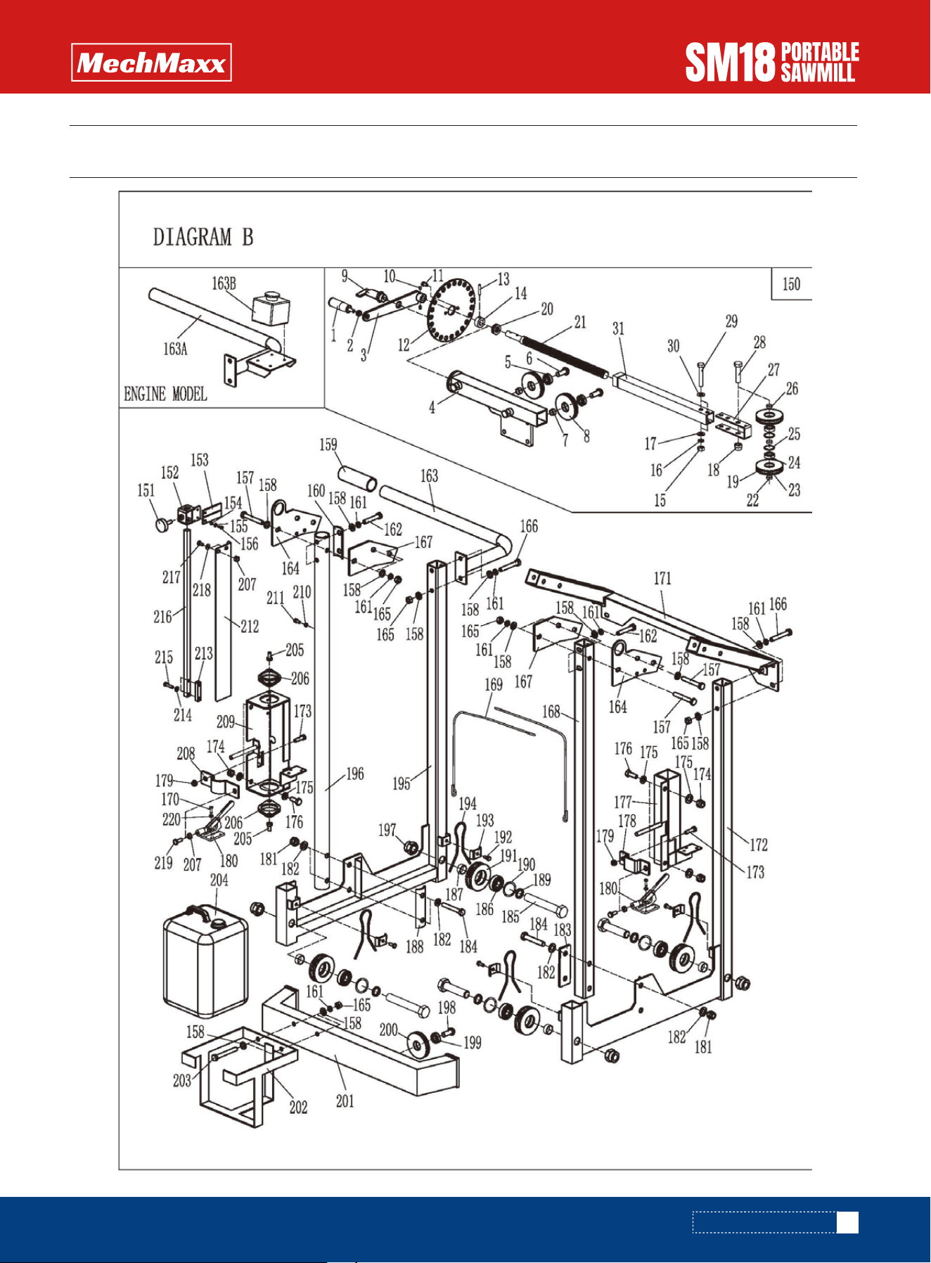
DIAGRAM(B)-CARRIAGE
DIAGRAM(B)-CARRIAGE

34
www.mechmaxx.com
DIAGRAM LIST(B)-CARRIAGE
PARTS LIST(B)--CARRIAGE
REF DESCRIPTION
150
1
2
3
4
5
6
7
8
9
10
11
12
13
14
15
16
17
18
19
20
21
22
23
24
25
26
27
28
LIFT ASSEMBLY
LIFT HANDLE
HEX NUT
LIFT ARM
FIXED SLIDING TUBE
BEARING
ALLEN SCREW
SPACE BUSH
PULLY
INDEX ASM
SET SCREW
HEX BOLT
INDEX PLATE
SPRING PIN
FIXED BUSH
HEX NUT M10
SPRING WASHER 10
WASHER 10
HEX LOCK NUT M12
PAN HEAD SCREW M4X6
THRUST BEARING
THREADED SCREW
SPACER BUSH NO.1
PULLY
BEARING 6200
CIRCLIP FOR HOLE
SPACER BUSH NO.1
PULLY BRACKET
HEX BOLT M12X55
HEX BOLT M10X55
WASHER 10
INNER SLIDING TUBE
HANDLE M8X30
SLIDING PART
POINTER FOR HEIGHT
HEX NUT M4
WASHER 4
PAN HEAD SCREW M4X12
HEX BOLT M10X70
WASHER 10mm
HANDLE COVER
SPACER PLATE A
SPRING WASHER 10
HEX BOLT M10x55
PUSH-PULL HANDLE
JOINT PLATE A
HEX NUT M10
HEX NUT M10x65
JOINT PLATE B
SQUARE POST
STAINLESS WIRE
HEX BOLT M5
STRENGTHEN BRACKET
LEFT BRACKET
HEX BOLT M8x30
HEX LOCK NUT M10
WASHER 10mm
HEX BOLT M10X25
REF DESCRIPTION
29
30
31
151
152
153
154
155
16
157
158
159
160
161
162
163
164
165
166
167
168
169
170
171
172
173
174
175
176

35
www.mechmaxx.com
REF DESCRIPTION
177
178
179
180
181
182
183
184
185
186
187
188
189
190
191
192
193
194
195
196
197
198
199
200
201
202
203
204
205
206
207
SLIDING BRACKET L
LOCK PLATE NO.1
HEX LOCK NUT M8
LOCKING ASM
HEX LOCK NUT M12
WASHER 12mm
SPACER PLATE B
HEX BOLT M12x70
HEX BOLT M20X100
BEARING
SPACER BUSH, WHEEL
SPACER PLATE C
SPACER BUSH NO.2
CIRCLIP FOR HOLE
WHEEL
HEX BOLT M6X16
CLAMP PLATE
STAINLESS WIRE (S)
RIGHT BRACKET
ROUND SUPPORT
HEX LOCK NUT M20
ALLEN SCREW
BEARING
PULLY
JOINT BRACKET
SUPPORT POST FOR TANK
HEX BOLT M10X80
COOLANT TANK
HEX BOLT M8X16
SLIDING BUSH
HEX NUT M8
REF DESCRIPTION
208
209
210
211
212
213
214
215
216
217
218
219
220
LOCK PLATE NO.2
RIGHT BRACKET
SPACER BUSH NO.3
ALLEN SCREW M6x12
SCALE BRACKET
SPACER BLOCK
WASHER 6mm
HEX BOLT M6X25
SQUARE ROD
HEX BOLT M8X16
WASHER 8mm
HEX BOLT M8
HEX LOCK NUT M5
DIAGRAM LIST(B)-CARRIAGE
36
www.mechmaxx.com
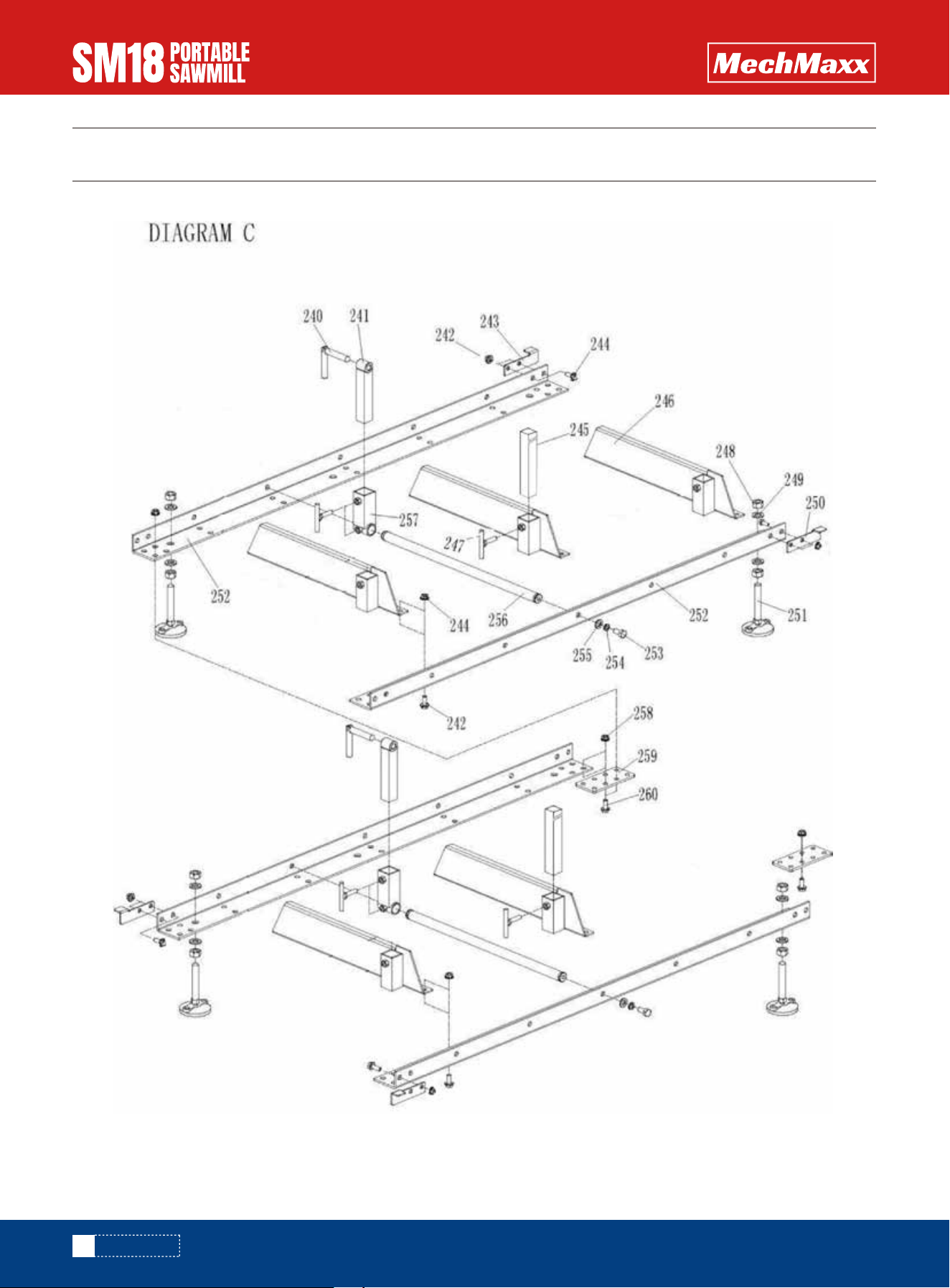
DIAGRAM(C)
DIAGRAM(C)

37
www.mechmaxx.com
PARTS LIST(C)
PARTS LIST(C)
REF DESCRIPTION
240
241
242
243
244
245
246
247
248
249
250
251
252
253
254
255
256
257
258
259
260
FOLDING HANDLE
MOVABLE CLAMP
HEX FLANGE BOLT M10X25
STOPPER NO.1
HEX FLANGE NUT M10
FIXED CLAMP
CROSS ARM
LOCK SCREW
HEX NUT M16
WASHER 16
STOPPER NO. 2
FOOT PAD
RUNWAY
HEX BOLT M12X25
SPRING WASHER 12
WASHER 12
SLIDING BAR
SLIDING BLOCK
HEX FLANGE NUT M10
JOINT PLATE
HEX FLANGE BOLT M10X25
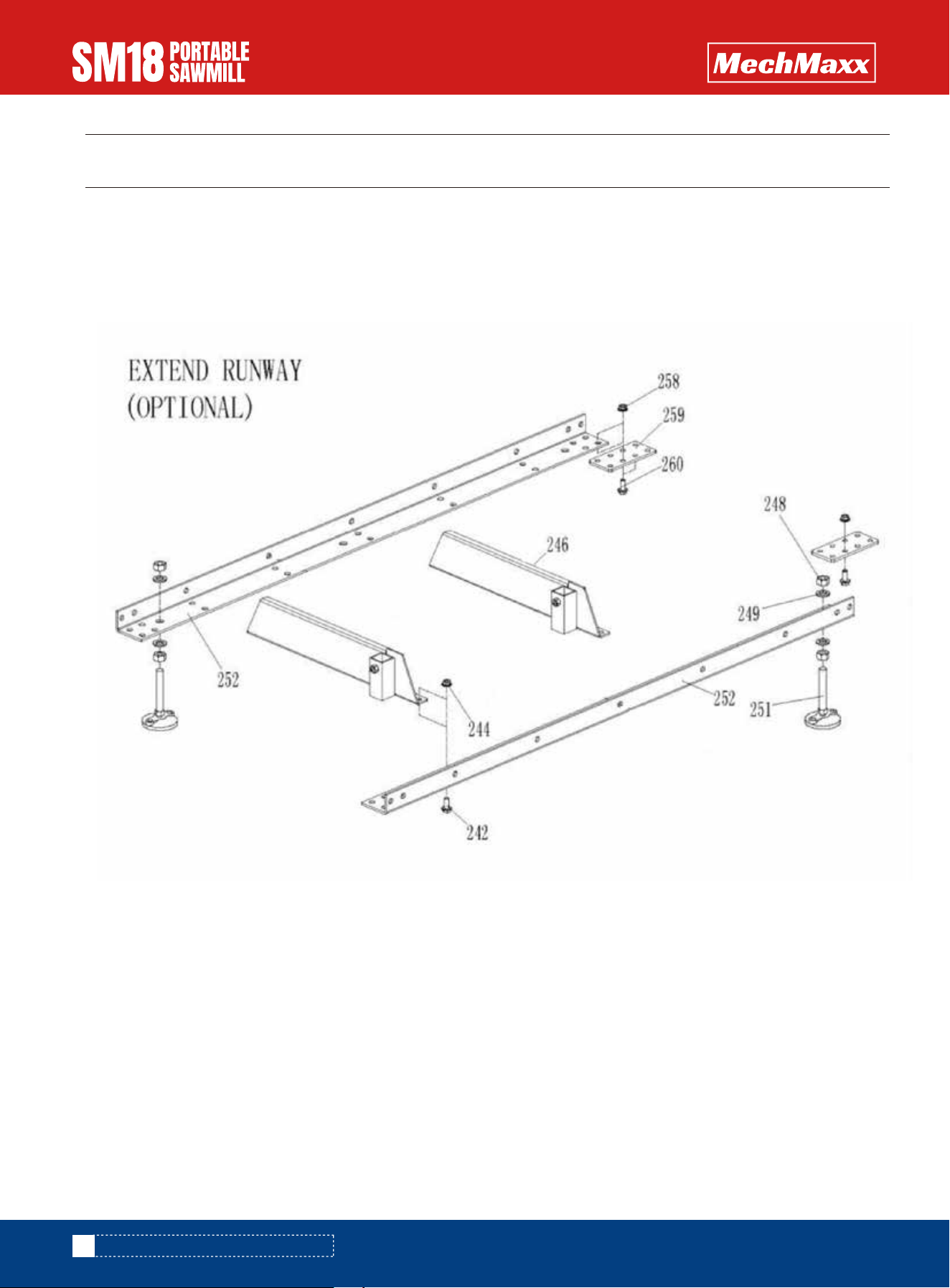
DIAGRAM(C)-EXTEND RUNWAY (OPTIONAL)
38
www.mechmaxx.com
DIAGRAM(C)-EXTEND RUNWAY (OPTIONAL)

39
www.mechmaxx.com
PARTS LIST(C)-EXTEND RUNWAY (OPTIONAL)
PARTS LIST(C)-EXTEND RUNWAY (OPTIONAL)
REF DESCRIPTION
242
244
246
248
249
251
252
258
259
260
HEX FLANGE BOLT M10X25
HEX FLANGE NUT M10
CROSS ARM
HEX NUT M16
WASHER 16
FOOT PAD
RUNWAY
HEX FLANGE NUT M10
JOINT PLATE
HEX FLANGE BOLT M10X25