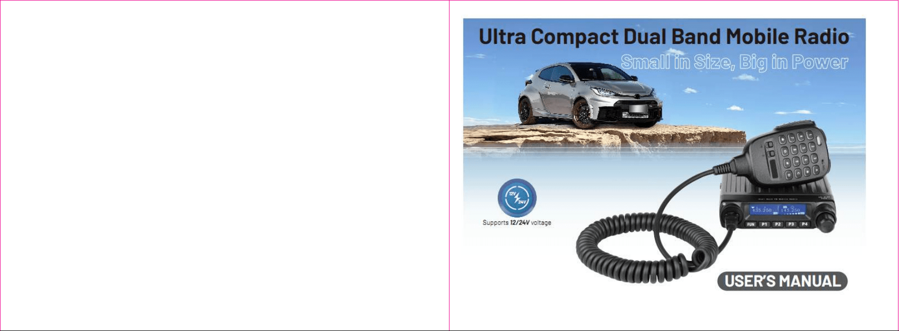

成品尺寸14.3x10.5cm
our
Though friendly design for user,this transceiver is technically complicated and some features maybe
be new to you.Considering this manual to be a personal tutorial from the designers,allow the manual to
guide you through the learning process now,then act as a reference in the coming years.
Please observe the following precautions to prevent fire, personal injury, or transceiverdamage:
Do not attempt to configure your transceiver while driving,it is dangerous.
This transceiver is designed for a 12V and 24V DC power supply.
Do not place the transceiver in excessively dusty, humid or wet areas, nor unstablesurfaces.
Please keep it away from interferential devices (suchas TV, generator etc.)
Do not expose the transceiver to long periods of directsunlight nor place it close to heating applianc-
es.
If an abnormal odor or smoke is detected comingfrom the transceiver, turn OFF the power immedi-
ately.Contact local service station or your dealer.
Do not transmit with high output power for extended periods; the transceiver mayoverheat.
Please contact the local authorized dealer if you have any questions.We are not responsible for any
typographical errors that may by in this manual.Standard accessories may change without noice,
getting your understanding for any inconveniences.
When programming the transceiver,need the factory initial data firstly, and then rewrite the frequency
and signaling etc.Otherwise errors may occur because of different frequency band etc.
Precautions
1313

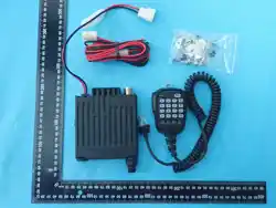
Supplied Accessories
Installation
Functions and features
Getting Acquainted
Basic operation
Menu function instruction
Signalings
Specifications
CONTENTS
01
03
10
11
18
25
29
38
Professional FM Transceiver
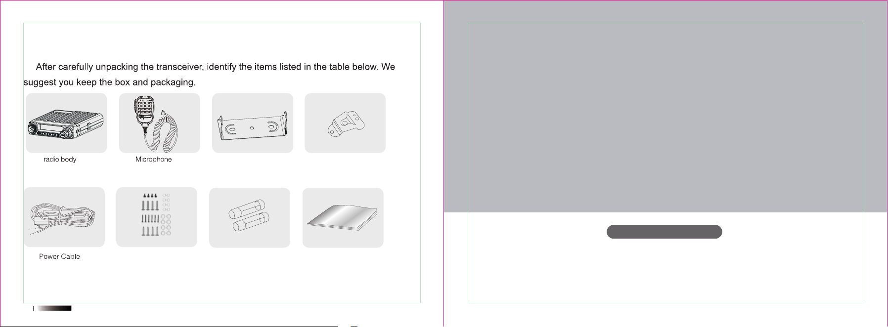
Supplied Accessories
User’s Manual
Professional FM Transceiver
Installation
User’s Manual
02
Hardware Fuse*2 User's Manual*1
*1 *1
1 2 3
4 5 6
7 8 9
A
ENT
B
VFO
C
MR
D
A/B
#
UP
0
MUTE
*
DWN
*1
*1
Panel bracket
Microphone bracket*1
Supplied Accessories/Optional Accessories
Supplied Accessories
04
05
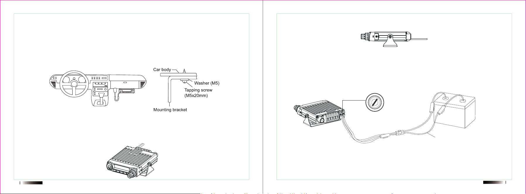
Mobile installation
To install the transceiver,select a safe,convenient location inside your vehicle thatminimizes danger to
your passengers and yourself while the vehicle is in motion.Considerinstalling the unit at an appropriate
position so that knees or legs will not strike it duringsudden braking of your vehicle.Try to pick a well
ventilated location that is shielded fromdirect sunlight.
1.Install the mounting bracket in the vehicle using the supplied self-tapping screws(4pcs)and flat
washers(4pcs).
2.Position the transceiver,hen insert and tighten the supplied hexagon SEMS screws.
■ Double check that all screws are tightened to prevent vehicle vibration from loosening the bracket
or transceiver.
■ Determine the appropriate angle of the transceiver,using the screw hole positions on the side of the
mounting bracket.
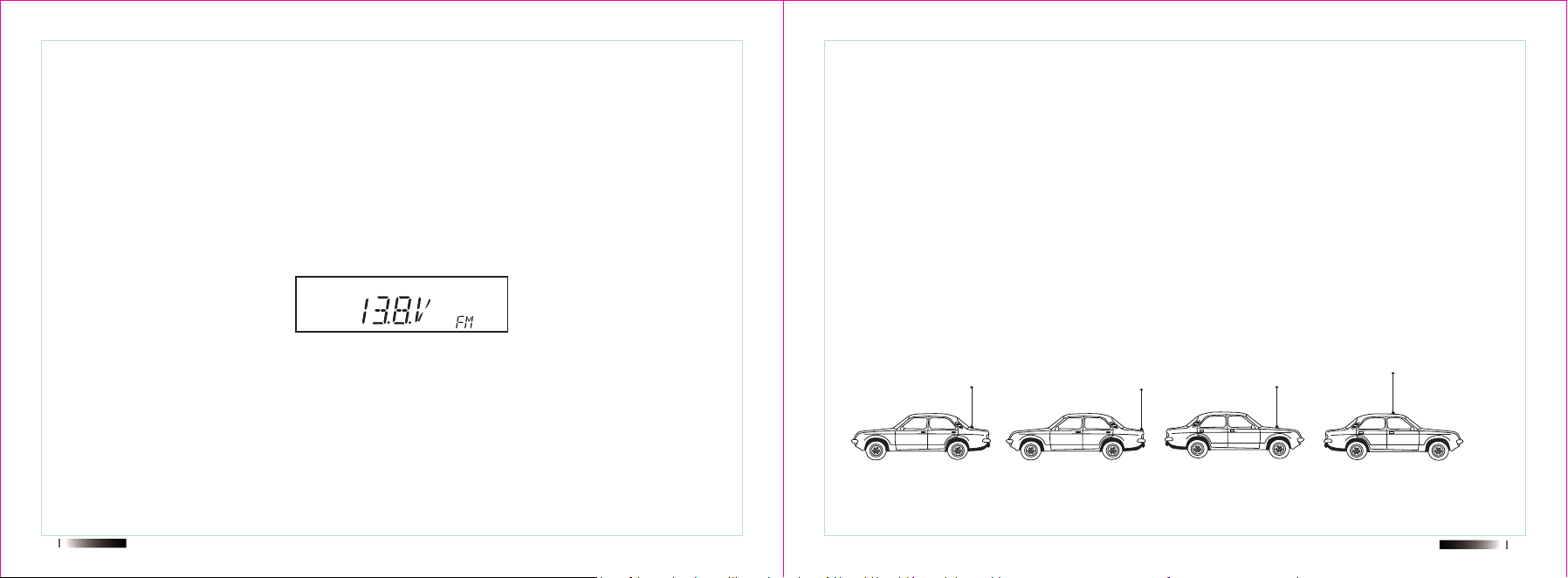
DC Power Cable Connection
NOTE:Locate the power input connector as close to the transceiver as possible.
This transceiver is designed for a 12V and 24V DC power supply.
Initial Installation
Mobile Operation
Car Battery
DC Power Cable
Mobile Radio
+12V Ignition Switch
LOCK
ACC
ON
START
06
07
1.Route the DC power cable supplied with the transceiver directly to the vehicle's batteryterminals
using the shortest path from the transceiver.
■ We recommend you do not use the cigarette lighter socket as some cigarette lighter
sockets introduce an unacceptable voltage drop.
■ The entire length of the cable must be dressed so it is isolated from heat,moisture,and
the engine secondary (high voltage)ignition system/cables.2.After installing cable,in order to avoid the
risk of damp,please use heat-resistant tap totie together with fuse box.Don't forget to reinforce whole
cable.
The transceiver will return to its normal operation when the power is switched ON orrepeat above
operation.
Antenna Connection
Before operating,installan efficient,well-tuned antenna.The success of your installationwill depend
largely on the type of antenna andits correct installation.The transceiver cangive excellent results if the
antenna system and its installation are given careful attention.Use a 50Ω impedance antenna and
lowHoss coaxial feed-line that has a characteristicimpedance of 50Ω,to match the transceiver input
impedance.Coupling the antenna tothe transceiver via feed-lines having an impedance other than
50*reduces the efficiencyof the antenna system and can cause interference to nearby broadcast
television receivers,radio receivers,and other electronic equipment.
NOTE:Transmitting without first connecting an antenna or other matched load may damagethe
transceiver.Always connect the antenna tothe transceiver before transmitting.
All fixed stations should be equipped with a lightning arrester to reduce the risk of fire,electric shock,and
transceiver damage.
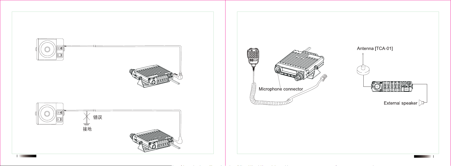
The possible locations of antenna on a car are shown as following:
R
08
09
Accessories Connections
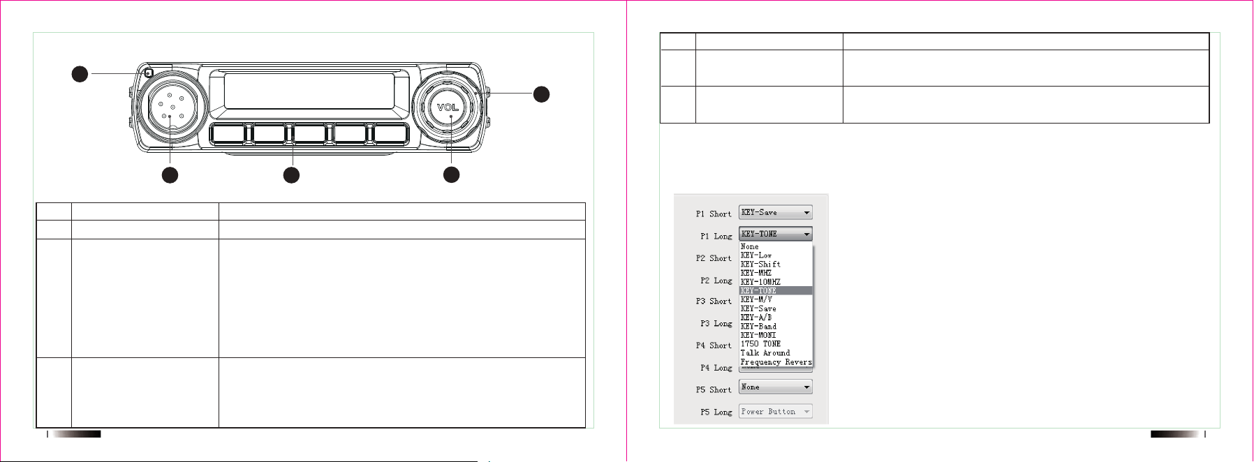
External Speaker
■ If you plan to use an external speaker,choose a speaker with an impedance of 8Ω.Theexternal
speaker jack accepts a 3.5 mm(1/8")mono (2-conductor)plug.
NOTE:External speaker adopt double port BTL,please care about the connecting way.The speaker can
not connect with the ground,otherwise the speaker will be fault.Thewrong connecting way as the follow-
ing picture.
Microphone
■ For voice communications,connect a microphone equipped with an 8-pin modular pluginto the
modular socket on the front of the main unit.Press firmyly on the plug until thelocking tab clicks.At-
tachthe supplied microphone hanger in an appropriate location usingthe screws included in the screw
set.

Professional FM Transceiver
Getting Acquainted
10
Functions and features
■ Supports 12/24V voltage
■ Dual band,dual wait,dual standby,dual watch
■ Speaker gain
■ Mic Gain
■ Auto power off
■ DOT-MATRIXLCD Display
■ 200 channels
■ FM radio for 32 channels storage
■ Wide/Middle/Narrow bandwidth select
■ High/Middle/Low power select
■ Talk permit tone
■ Roger tone
■ Sub band tone
■ Remote stun/kill/activate
■ TOT
■ ANI
■ PTT ID
■ DTMF encoding and decoding
■ 2 Tone/5 Tone encoding and decoding
■ Scrambler
■ CTCSS/DCS
■ Programmable keys
■ Backlight brightness setting
User’s Manual
12
13
Mic connector/DATA
FUN,PI,P2,P3,P4 key
Turnning Control
Microphone connection port/PC programming data port
Long press Fun key to enter menu/Fun+P5:Enter menu
Default setting as below:
FUN+P1: FM RADIO
Fun+*: Main/Sub channel switch
Fun+P2: Lock
Fun+P3: CTCSS/DCS setting
Fun+#:Emergency call
a.Rotate this knob can choose the VFO frequency,Channel
number,Tone value,Scan direction.
b.When operating band is MR model or channel mode,press
[Turnning Control] can switch the channel.
NO. Key Function
01
02
03
P5
Indicator light
P5-- volume knob
Long press P5 to power on the radio
Red Light during transmit
Green light during receive
NO. Key Function
04
05
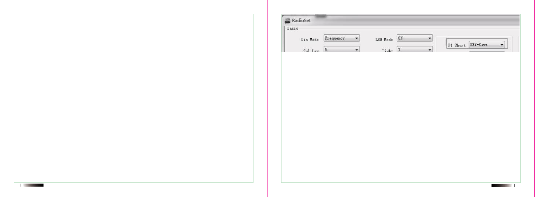
P1-P5 short and long press setting you can do it by software as you requirement.
Software-Basic---Radioset
Choice as below:
Front panel buttons’ definitions
FUN
P1 P2 P3 P4
�� ��
��
��
��
H,M,L
CTC,DCS
N,M,W
+, -
2T,5T,DT
A
DW
VFO
001
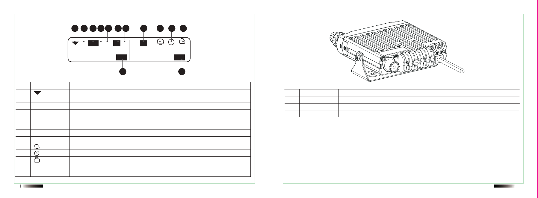
Home screen
High power output/Middle power output/Low power output
CTCSS /DCS encode or decode
Narrow bandwidth/Middle bandwidth/Wide bandwidth
Positive direction of offset/Negative direction of offset
Signaling
AM mode
Dual wait
Beep
Auto Power-off
Lock the keypad
Frequency mode
Channel mode
No. Icon Function
01
02
03
04
05
06
07
08
09
10
11
12
13
14 15
Display Rear Panel
H H A
CTC
VFO 001
5T
DW
+
+
+
Ant
EXT SP
EXT DC
Connection to 50Ω Antenna
Terminal for optional external speaker
DC power cable connection
No. Description Function
01
02
03
�� �� �� �� �� �� �� �� �� �� ��
�� ��
435.25000 145.25000
1 2 3
4 5 6
7 8 9
A
B
C
D
#
UP
0
MUTE
*
DWN
D
*
#
Key lock
Keypad light
Short press D--Fun menu
Long press D---Radio menu
Lock/Unlock
Long press # ---FM Radio
Key lock on or off
Keypad light on or off
No. Icon Function
09
10
11
12
13
16 17
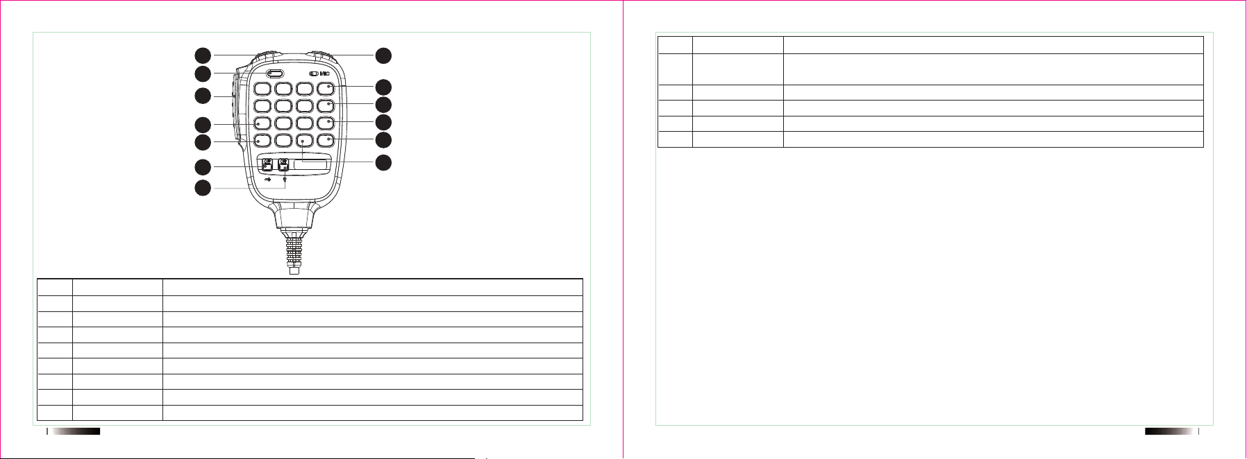
Microphone
PTT
Down
Up
Indicator light
Number key
A
B
C
Press the key to transmit
Decrease setting value
Increase setting value
Indicator light will red during transmit and green during receive.
Input channel number or DTMF dial out etc
VFO mode and MR mode
Long press B---transmit
Under VFO mode,long press C to enter one key frequency copy
No. Icon Function
01
02
03
04
05
06
07
08
��
��
��
��
��
��
��
��
��
��
��
��
��

Professional FM Transceiver
Basic Operation
19
Basic Operations
Power on/off
Long press the P5 button to switch the radio ON.
-The power on message momentarily appears on the display.
-If the transceiver power on password has been activated,you must first enter your password before you
can operate the transceiver.
Long press P5 button again to switch the radio OFF.
Adjusting the volume
Rotate P5(volume knob) clockwise to increase the volume and counterclockwise to decrease the
volume.
Switch between VFO and channel Mode
In standby,press microphone “A” key,the indicates will display current channel in channel mode.Repeat
above operation to switch between Frequency(VFO) mode and channel mode.
Adjusting Frequency/channel
Under Frequency(VFO) mode, you can change the current frequency to the desired one through
[Turnning Control];Turn clockwise to increase frequency,turn counterclockwise to decrease.Or you can
do it by “Down” or “Up” key at microphone.
In frequency mode, you can rotate the knob and change the standby frequency in steps.This product
has 8 step sizes for users selecting:2.5K,5K,6.25K,10K,12.5K,25K,50K,100K.
User’s Manual
20
21
You can also press the number keys to enter the waiting frequency you need to switch in sequence.
For example, switch to 455.125MHz and press 【 4 】, 【 5 】, 【 5 】, 【 1 】, 【 2 】, 【 5 】.
In the channel mode,you can change the current channel to the desired one through [Turnning Control]
or microphone “up” and “down”.
You can also press the number keys to enter the channel number you need to switch sequentially.
For example, switch to CH001 and press 【 0 】, 【 0 】, 【 1 】; Switch to CH128 and press 【 1 】,
【 2 】, 【 8 】. When you want to switch to a channel between CH030-CH099, you can also directly
enter the last two digits of the channel number; If switching to CH034, connect to 【 3 】 and 【 4 】;
Switch to CH099 and press 【 9 】 or 【 9 】.
Receiving
When the channel you are operating is called,the screen will show R and S meter appears on
display.The indicator light show green at receiving status.
Transmitting
Press PTT and hold on and speak to the microphone to transmit,the screen will show T _ _ appears
on display.The indicator light show red at transmit status.
Channel store or delete
Preset the key-save function by software.For example set this function at P1 Short.
1.Under frequency mode(VFO),turn [Turnning Control] to select the desired frequency or input frequen-
cy by Mic’s number keys.
2.Select the desired CTCSS/DCS signaling in the menu 23-25th.
3.Short press P1 to enter storage or delete mode,the channel number of screen will flashing.
4.Turn [Turnning Control] to select the desired channel number to store or input directly by microphone.
5.Press Fun key or P5 to store current channel.Press P2 to delete the current channel.
6.Press P4 to exist.
VFO offset setting
Under VFO mode, enter Menu 22 to set magnitude of the repeater shift, enter menu
26 to set the shift direction, synthesizer Steps can be changed through menu item 27.
For example, if your frequency now is 445.0500MHz, would like to set a frequency
444.4500MHz as transmit frequency, steps as below:
1.Under VFO mode, enter Menu 22 to set the offset at 0.6MHz,press F to confirm.
2.Enter menu 26 to set shift direction at “-“,press [Fun] to confirm.
3.Press PTT button will show transmit frequency at 444.4500MHz.
22
23
Operation of the composite key
Press Fun to enter below page:
Then press the key below to achieve default function.
1.Press the “FUN+*” to switch home screen and sub screen.
at where, which screen is home screen
2.FM radio function(FUN+P1)
1) On/off radio receiver
Under standby mode, press [FUN+P1 ] or directly long press [#] at microphone to open FM radio
function , LCD
display “90.4M”, then press [FUN+P1 ] again, radios receiver is off
2)Mode selection
Under FM radio mode, press [A ] to switch between FM memory mode and FM frequency mode (this
function is unavailable when there is not FM memory channel).
3) Frequency selecting
Under FM frequency mode, input the digits directly by keypad or press the [Turning Control] to choose
the desire frequency.
Under FM memory,press the [Turning Control] to choose the desire channel.
4)FM radio storage
Under FM frequency mode,press [P1] which you set key-save function, the channel number
for storage blinks at the right of the screen.Press [Turning Control] select the desired channel number.
Press[FUN] key to confirm and then back to the receiving mode.
5) FM radio channel delete:
Under FM frequency mode, press [P1] which you set key-save function, the channel number
for storage blinks at the right of the screen.Press [Turning Control] select the desired channel number.
Press[P2] key to delete the channel.
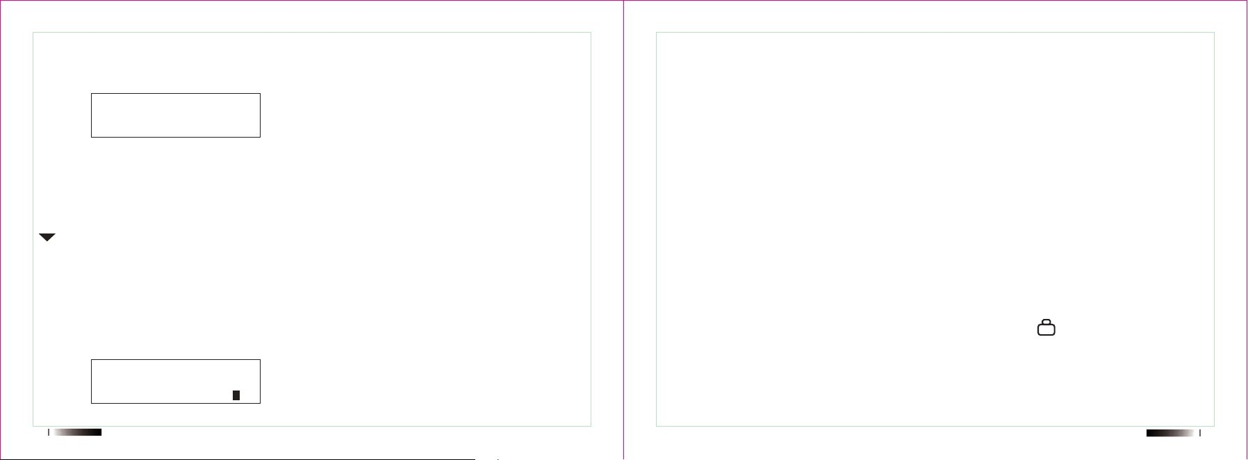
Keypad lock setting(FUN+P2)
Under standby mode, press [* ] for 2 S to lock to unlock the keypad.“ ” will be displayed at the top
of LCD when keypad is locked.
And you can Enter Menu 32[LOCK MD] to set Keypad lock method:ALL/PTT/KEY/K+S lock.
+
Menu
FUN P1 P2 P3 P4
Radio
90.4
5

Professional FM Transceiver
Menu function instruction
User’s Manual
24
DCS/CTCSS setting(FUN+P3)
This function is used to receive and transmit CTCSS/DCS frequency.(The current channel should be
have CTCSS/DCS)
1. Press the [Fun] key during standby to enter the menu operation interface and select menu 23
2. Press the [Fun] key to confirm and enter the settings mode.
Press the P1 key to switch the signaling type (OFF->DCS).
4. Select the DCS/CTCSS you need.
5. When selecting signaling as DCS, press the P2 key to choose the DCS direction.
6. Press [Fun] to confirm after completing the settings.
Set the receive tone coder and transmit tone coder in the same manner as the above operation.
Frequency copy
At VFO mode, Long press “C” at microphone to open one key frequency copy function, the screen will
show:Auto Scan.
Using the other radio to transmit,the frequency will copy to your mobile radio.
Support different brand radio copy.
Emergency Alert(F+#)
Under standby mode, press [FUN ] to enter menu setting. LCD display “MENU”,then press [#]to turn on
emergency alert function,radio will transmit emergency ring,until you press PTT,it will exit.
26 27
Menu function instruction
1.There are three ways to enter menu:
-Long press “Fun” key to enter menu
-”Fun” + P5 power on channel
-Long press “D” key at microphone to enter menu
2.Rotating the [Turnning Control] to choose the desire menu or using microphone “UP” or “Down” to
choose or directly input the desire menu by microphone number key.
3.Press “Fun” key to enter and set the current menu.
4.Press [Turnning Control] to select desire value of current menu .
5.Press “Fun” key to save selected value.
6.Repeat the steps of 2-5 can set more value.
Scan
STE
TX.SEL
POW
SQL
D.WATT
LED
LIGHT
BEEP
DT CH
TOT
ON
Frequency/120/180/240/OFF
Main CH/Last CH
HIG/MID/LOW
0-9 Level
ON/OFF
ON/5S/10S/15S/20S/25S/30S/OFF
1-7
ON/OFF
1-16
OFF/30/60/90/120/150/180/210/240/270
Scan
End Tone Eliminator
TX Channel
High/Middle/Low TX Power
Squelch Level Setting
Dual Wait/Standby
LED Display Mode
Back Light Setting
Keypad Beeper Setting
Preset Channel Setting
Time-out-Timer
No. Display Setting values Description
01
02
03
04
05
06
07
08
09
10
11
BCLO
Signal
Roger BP
Code
SCAN
AUTO LK
Pow off
OPNSET
DC VOLT
OFF SET
DIS.NM
C-CDC
R-CDC
T-CDC
S-D
STEP
N/W
SEEK
SEEK
SCR.NO
LOCK MD
DIS MD
FM Moni
CH.NAME
OFF/SUB/Carrier
OFF/DTMF/2 Tone/5 Tone
ON/OFF
ON/OFF
TO/CO/SE
ON/OFF
OFF/30 minute/60 minute/120 minute
DC/Char/MEG/OFF
/
0.000-99.995MHZ
ON/OFF
OFF/67.0/D023N
OFF/67.0/D023N
OFF/67.0/D023N
OFF/+/-
2.5K/5K/6.25K/10K/12.5K/25K/50K/100K
WIDE/MIDD/NARR
67
D023N
OFF/1-8
ALL/PTT/KEY/K+S
FRE/CH/MR
ON/OFF
Busy Channel Lock-out
Signal Select
Transmit Over Beeper
Power on Password
Scan Mode
Auto Keypad Lock
Auto Power Off
Power-on Display
DC Voltage
Repeater Shift(Under VFO Mode)
Power-on Display
TX/RX Tone Coder
RX Tone Coder
TX Tone Coder
Shift Direction
VFO Step
Bandwidth Select
CTCSS Scanning
DCS Scanning
Voice Scramble
Lock Mode
Work Mode Setting
FM Radio
Display Channel name
No. Display Setting values Description
12
13
14
16
17
18
19
20
21
22A
22B
23
24
25
26
27
28
29
30
31
32
33
34
35
Professional FM Transceiver
SIGNALINGS
User’s Manual
28
MIC LEV
RX.LIGHT
TalkPrmt
Ch Alert
Spk Gain
Reset
Ver:
1-8
ALW.ON/CODE.ON/OFF
ON/OFF
ON/OFF
Normal/1-7
ALL/VFO/FULL
MUC/T
Microphone Sensitive Level
Receiving Light
Talk Permit
Receive Alert
Speaker Gain
Reset Function
Radio Version
No. Display Setting values Description
36
37
38
39
40
41
42
30 31
SIGNALINGS
Press the [PTT] and [UP] key at microphone to achieve remote kill/stun/active.
DTMF
When the signal of the channel selects the DTMF, press PTT and at the same time press
【UP】key at microphone, the current channel will automatically check if the DTMF signaling is
received and decoding it. And achieve a corresponding function according to the received code.
The function including: ANI display, remote stun/waken/kill.
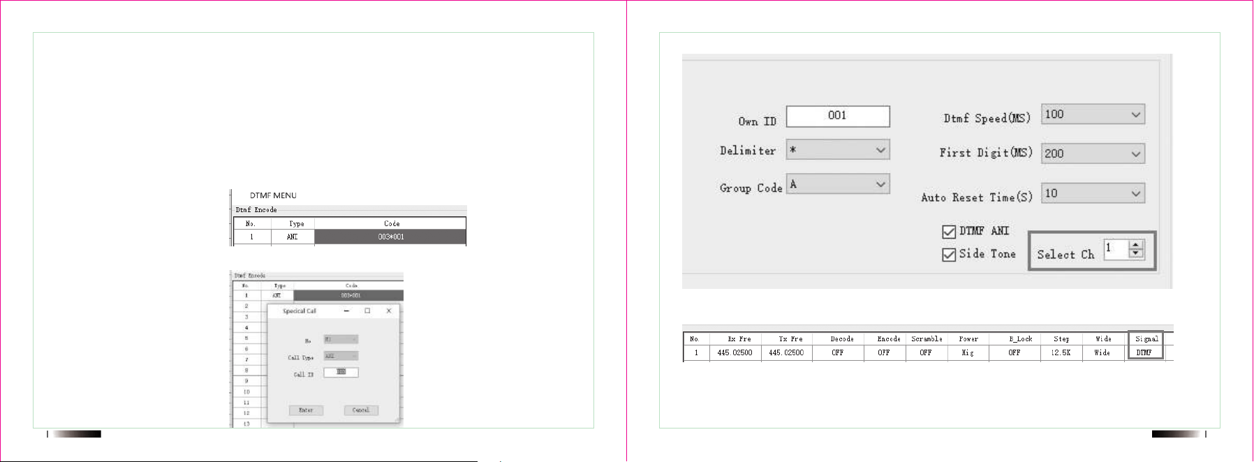
ANI Display:
1.DTMF Encode type choose ANI:
2.Input the called ID, eg, your radio ID is 001, the called radio ID is 003
3.Select channel NO.
4.Choose DTMF signal
5.Press PTT and side key【UP】key at the microphone at the same time to achieve the ANI display
function.
32 33
Remote stun, remote kill function
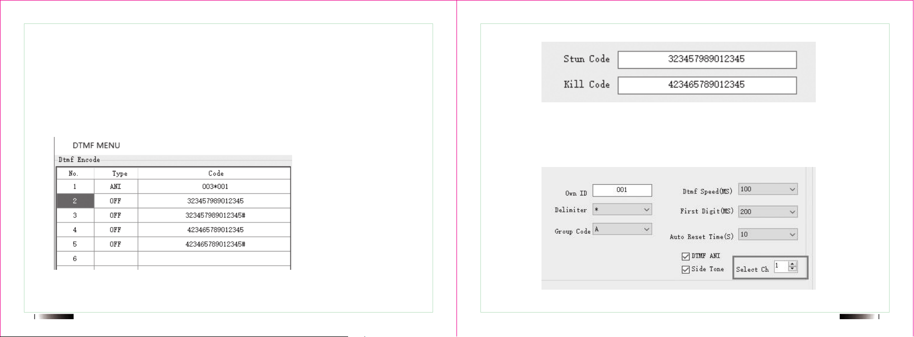
Stun code: when the radio receives the corresponding DTMF code, the radio will be remote stunned
and disabled transmit.
Kill code: when the radio receives the corresponding DTMF code, the radio will be remote killed and
disabled receive and transmit.
Waken code: release the state of stun/kill.
Select Ch: the default channel when the DTMF is calling.
1.DTMF Encode type choose OFF, user can input the desired DTMF code directly.
2.In transmitting ,input the remote kill/stun code for the radio which you want to remote kill/stun.
3.DTMF Encode:
Remote receive code :”remote stun code + #” to waken radio which at stun state
Remote receive code:”remote kill code + #” to waken radio which at kill state
4.Select channel
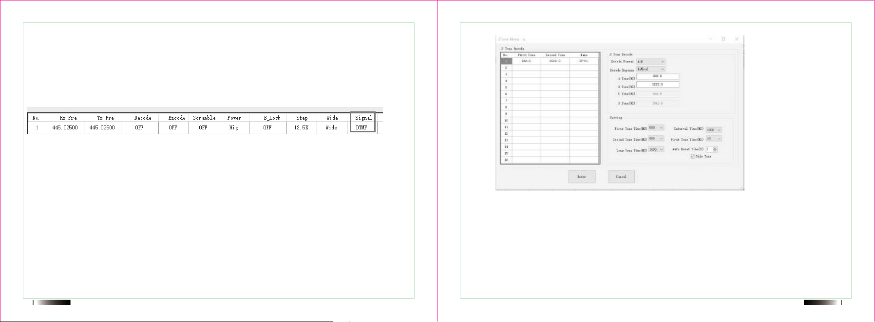
34 35
Like above setting,
Channel 1: ANI display,
Channel 2:remote stun code
Channel 3:remote waken from stun state
Channel 4:remote kill code
Channel 5: remote waken from kill state
6.Remote kill/waken/stun operation.
After setting like above, if you would like to achieve Radio A kill Radio B, there are two way to
achieve:
One: At programming software DTMF setting choose Ch 4.
Then press the PTT and【UP】key at microphone to achieve remote radio B.
Two: At radio, choose Menu 10th—DT CH—Channel number choose 4.
Then press the PTT and【UP】key at microphone to achieve remote radio B.
Similar operation for remote stun/waken.
5.Signal choose DTMF
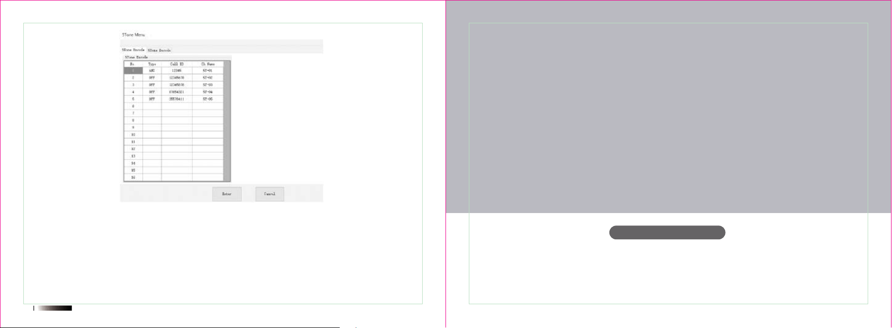
2 TONE Operation
2 Tone encode
Input: the frequency of first tone and second tone
Note: the frequency between of the first tone and second tone should not too similar to avoid the decod-
ing is wrong.
2 Tone decode
Decode Format: the combination of decode, for example: A-B, you should make sure the frequency of
first tone is A, and second tone is B. Other combination is similar.
Professional FM Transceiver
SPECIFICATION/GUARANTEE
User’s Manual
36
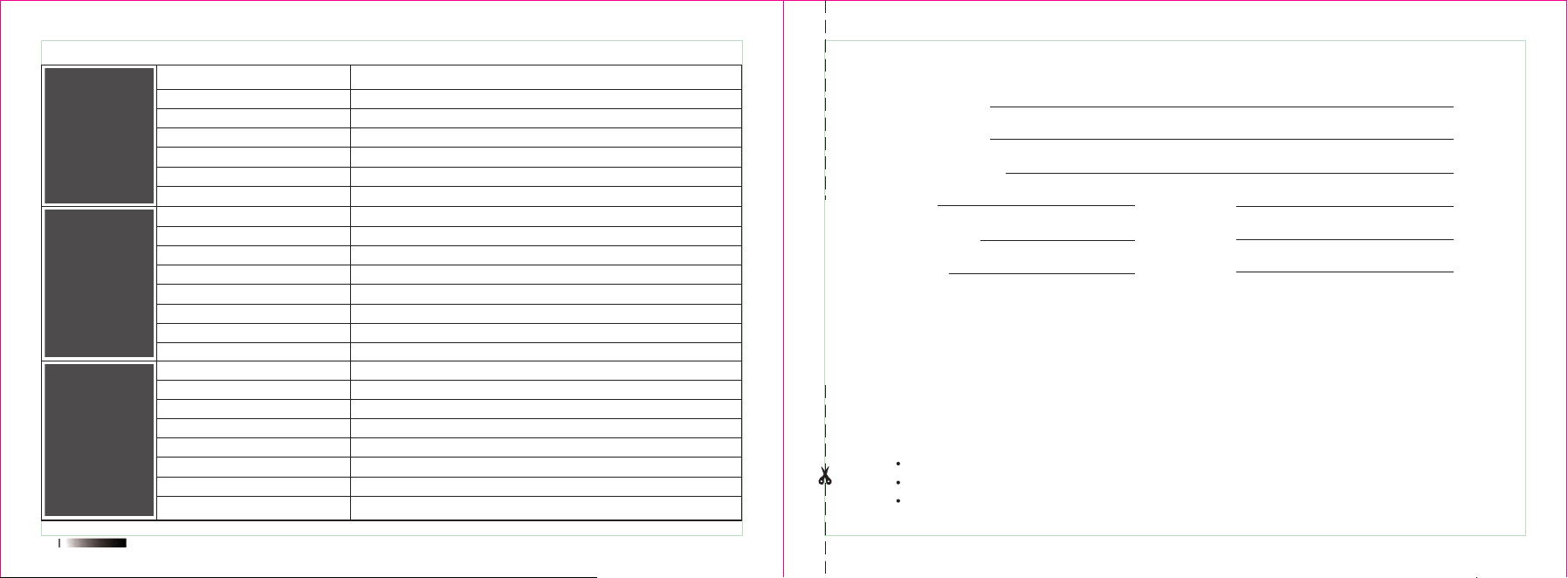
5 Tone Operation
5 Tone encode
The write way is same with the DTMF.
5 Tone decode
Function: The function will be achieved when the radio receives the corresponding code.
Select: Turn on squelch
Stun/kill: same with DTMF
Wake: release the state of stun/kill
38
General
Transmitter
Receiver sensibility
Adjacent channel selectivity
Intermodulation
Spurious rejection
Audio response
Audio distortion
Audio power
FM Hum and Noise
Receiver
RF output power
Transmit current
Standby current
FM modulation
Modulation distortion
FM Hum and Noise
Adjacent channel power
Audio response
Frequency range
Channels
Frequency stability
Working temperature
Operating voltage
Size (HxWxD)
Weight
0.2μV @ 12dB SINAD
≥60dB /≥65dB
≥70dB
+1~-3dB
<5%
3W
≥45dB@25KHz /≥40dB @12.5KHz
UHF 25W / VHF
≤4.5A
0.2A
11kΦF3E / 16kΦF3E
<5%
≥45dB@25KHz /≥[email protected]
+1~-3dB
EU 144-146 &430-440MHz /US 144-148&420-450Mhz
200
±1ppm
-10℃ ~ + 60℃
13.8V DC
145x108x21.5mm
422g
SPECIFICATION
Please cut along with this line
GUARANTEE
Model Number:
Serial Number:
Purchasing Date:
Dealer:
User's Name:
Address:
Telephone:
Telephone:
Post Code:
Remarks:
1
2
3
4
5
This guarantee card to be kept by the user, no replenishment if lost.
This guarantee card to be filled & chopped by the dealer, or it is invalid.
Don't alter the guarantee card, please coufirm the serial number on the guarantee card is same as
that on the machine.
One-year guarantee, charger, battery, ear-phone, antenna and cable are not under guarantee.
The user can get repairing service from the followingways:
Go to the shop where you buy the machine.
Our local repairing agents.
Send back to our company.
25W max

SPECIFICATION
NOTE: This equipment has been tested and found to comply with the limits for a Class B
digital device, pursuant to part 15 of the FCC Rules. These limits are designed to provide
reasonable protection against harmful interference in a residential installation. This
equipment generates uses and can radiate radio frequency energy and, if not installed
and used in accordance with the instructions, may cause harmful interference to radio
communications. However, there is no guarantee that interference will not occur in a
particular installation. If this equipment does cause harmful interference to radio or
television reception, which can be determined by turning the equipment off and on, the
user is encouraged to try to correct the interference by one or more of the following
measures:
-Reorient or relocate the receiving antenna.
-Increase the separation between the equipment and receiver.
-Connect the equipment into an outlet on a circuit different from that to which the receiver
is connected.
-Consult the dealer or an experienced radio/TV technician for help.
CE statement
We declare that the radio is compliance with Radio equipment Directive (RED) 2014/53/EU.
The full text of the EU declaration of conformity is available at the following internet address: xxxxxx
The device in the environment with the temperature between -10-60℃. and operating under 2000m, otherwise, it
may damage your device.
This equipment complies with RF radiation exposure limits set forth for an uncontrolled environment. This
equipment shall be installed and operated with minimum distance 110 cm between the radiator & body.
Prohibit the use of non-original antenna, if the antenna is damaged, please contact the dealer for replacement,
support the frequency range of 144-146/430-440Mhz external antenna gain 3dBi max /50 ohms.
CAUTION:
RISK OF EXPLOSION IF BATTERY IS REPLACED BY AN INCORRECT TYPE. DISPOSE OF USED
BATTERIES ACCORDING TO THE INSTRUCTIONS.

Changes or modifications not expressly approved by the party responsible for compliance
may void the user’s authority granted by the local government radio management
departments to operate this radio and should not be made. To comply with the
corresponding requirements, transmitter adjustments should be made only by or under the
supervision of a person certified as technically qualified to perform transmitter mainte-
nance and repairs in the private land mobile and fixed services as certified by an organiza-
tion representative of the user of those services.
Replacement of any transmitter component (crystal, semiconductor, etc.) not authorized
by the local government radio management departments equipment authorization for this
radio could violate the rules.
Changes or modifications not expressly approved by the party responsible for compliance
could void the use’s authority to operate the equipment. This device complies with Part 15
of the FCC Rules. Operation is subject to the following two conditions:
(1)this device may not cause harmful interference, and
(2)this device must accept any interference received, including interference that may
cause undesired operation.
WARNING: MODIFICATION OF THIS DEVICE TO RECEIVE CELLULAR RADIOTELEPHONE SERVICE SIGNALS IS
PROHIBITED UNDER FCC RULES AND FEDERAL LAW.

